
ProCurve MSM313 - Access Point HP - Free user manual and instructions
Find the device manual for free ProCurve MSM313 HP in PDF.


| Product Type | Wireless Access Point |
| Brand | HP |
| Model | ProCurve MSM313 |
| Wireless Standard | IEEE 802.11a/b/g/n (dual-band 2.4 GHz and 5 GHz) |
| Maximum Data Rate | Up to 300 Mbps |
| Ethernet Ports | 1 x 10/100/1000 Ethernet (PoE) |
| Power over Ethernet | Yes, 802.3af compliant |
| Power Consumption | 12.95W |
| Operating Frequency | 2.4 GHz and 5 GHz |
| Antenna Type | 2 x RP-SMA external antenna connectors |
| Mounting | Ceiling or wall mount (brackets included) |
| Security | WEP, WPA/WPA2, 802.1X, MAC filtering |
| Management | Web interface, SNMP, CLI, HP ProCurve Manager |
| LED Indicators | Power, LAN, WLAN activity |
| Dimensions (W x D x H) | 22.5 x 22.5 x 3.1 cm |
| Weight | 0.5 kg |
| Certifications | FCC, CE, IC |
| Operating Temperature | 0°C to 40°C |
| Humidity | 10% to 95% non-condensing |
| Warranty | Limited lifetime warranty |
Frequently Asked Questions - ProCurve MSM313 HP
User questions about ProCurve MSM313 HP
0 question about this device. Answer the ones you know or ask your own.
Ask a new question about this device
Download the instructions for your Access Point in PDF format for free! Find your manual ProCurve MSM313 - HP and take your electronic device back in hand. On this page are published all the documents necessary for the use of your device. ProCurve MSM313 by HP.
USER MANUAL ProCurve MSM313 HP
HP MSM313/MSM323 Integrated Services Access Points
Management and Configuration Guide
© Copyright 2010 Hewlett-Packard Development Company, L.P. The information contained herein is subject to change without notice.
This document contains proprietary information, which is protected by copyright. No part of this document may be photocopied, reproduced, or translated into another language without the prior written consent of Hewlett-Packard.
Publication Number
5998-0448
July 2010
Trademark Credits
Windows NT®, Windows®, and MS Windows® are US registered trademarks of Microsoft Corporation.
Disclaimer
HEWLETT-PACKARD COMPANY MAKES NO WARRANTY OF ANY KIND WITH REGARD TO THIS MATERIAL, INCLUDING, BUT NOT LIMITED TO, THE IMPLIED WARRANTIES OF MERCHANTABILITY AND FITNESS FOR A PARTICULAR PURPOSE. Hewlett-Packard shall not be liable for errors contained herein or for incidental or consequential damages in connection with the furnishing, performance, or use of this material.
The only warranties for Hewlett-Packard products and services are set forth in the express warranty statements accompanying such products and services. Nothing herein should be construed as constituting an additional warranty. Hewlett-Packard shall not be liable for technical or editorial errors or omissions contained herein.
Hewlett-Packard assumes no responsibility for the use or reliability of its software on equipment that is not furnished by Hewlett-Packard.
Warranty
See the Customer Support/Warranty booklet included with the product. A copy of the specific warranty terms applicable to your Hewlett-Packard products and replacement parts can be obtained from your Hewlett-Packard Sales and Service Office or authorized dealer.
Open Source Software Acknowledgement Statement
This software incorporates open source components that are governed by the GNU General Public License (GPL), version 2. In accordance with this license, Hewlett-Packard will make available a complete, machine-readable copy of the source code components covered by the GNU GPL upon receipt of a written request. Send a request to:
Hewlett-Packard Company, L.P. GNU GPL Source Code
Attn: HP Support
Roseville, CA 95747 USA
www.hp.com
Contents
Chapter 1
Introduction 9
About this guide....10
Products covered....10
Important terms....10
Conventions 11
Warnings and Cautions....12
Common deployments....12
Public access deployment....12
Multiple hotspots with AAA server....13
Enterprise deployment 13
Contacting support 14
Online documentation 14
Chapter 2
Working with VSCs 15
Key concepts ....16
User authentication....17
Management with VLANs....17
Working with autonomous APs....17
VSC configuration....18
About access control and authentication 18
If Provide access control is enabled....18
If Provide access control is disabled....19
VSC configuration options 19
Access control 19
Virtual AP....20
Quality of service 20
Allowed wireless rates 21
VSC ingress mapping 21
VSC egress mapping....21
Default user data rates 22
Wireless protection....22
WPA....22
802.1X 23
WEP....23
HTML-based user logins....24
MAC-based authentication 24
Location-aware 25
DHCP server 25
DHCP relay agent 26
VSC data flow 27
Stand-alone deployment: non access-controlled VSC 28
VSC on service controller 28
Stand-alone deployment: Access-controlled VSC 28
VSC on service controller 28
Deployed with an autonomous AP: Access-controlled VSC 29
VSC on AP 29
VSC on service controller 29
Using multiple VSCs 30
About the default VSC 30
Quality of service (QoS) 31
QoS priority mechanism 31
802.1p 31
VSC-based priority....32
Differential services (DiffServ) 32
TOS....33
IP QoS 33
Disabled 33
QoS example....33
Creating a new VSC 34
Chapter 3
Wireless configuration 35
Wireless coverage....36
Wireless mode 36
Factors limiting wireless coverage 36
Radio power....36
Antenna configuration....36
Interference 37
Physical characteristics of the location 37
Configuring overlapping wireless cells....37
Performance degradation and channel separation .....37
Selecting channels 38
Automatic power control....40
Conducting a site survey....41
Scanning frequency 41
Identifying unauthorized access points 42
Radio configuration 43
Configuration parameters 44
Mobility....48
Chapter 4
Network configuration 49
Port configuration....50
Port configuration information....50
Default port settings 50
Bridge port configuration ....51
Bridge spanning tree protocol....51
Bridge port....51
LAN port configuration 51
Management address....51
Link settings 52
Internet port configuration....52
Addressing options....52
Link settings 53
Network address translation 53
Address allocation 53
DHCP server (global) 54
Addresses 54
Settings....55
DHCP relay agent....55
Settings....56
Server 56
VLAN support 57
Types of VLANs....57
VSC-based VLANs 57
General VLANs....57
User-assigned VLANs 58
VLAN ranges....58
VLAN configuration....58
General 59
Assign IP address via....59
NAT....60
GRE tunnels 60
Bandwidth control....61
Internet port data rate limits 62
Bandwidth levels....62
Assigning traffic to a bandwidth level 62
Customizing bandwidth levels....62
Example 63
CDP....63
DNS 64
DNS servers....64
DNS advanced settings 64
IP routes 65
Configuration 66
Active routes 66
Default routes 66
Persistent routes....67
PPTP client 67
Network address translation (NAT) 67
NAT security and static mappings....68
NAT example....69
One-to-one NAT 70
RIP....71
IP QoS 71
Configuration 72
Settings....72
Example 73
Create the profiles....73
Assign the profiles to a VSC....74
IGMP proxy....74
Chapter 5
Management 77
Management tool 78
Management scenarios 78
Management station 78
Starting the management tool....78
Customizing management tool settings 79
Administrator authentication....79
Authenticating administrators using a RADIUS server.....79
Login control 80
Web server....80
Security......81
Auto-refresh....81
SNMP 81
Configuring SNMP settings....82
Attributes 82
Agent 83
Security......83
Traps....83
SOAP 84
Configuring the SOAP server 84
Server settings....84
Security......84
Security considerations 85
CLI 85
Configuring CLI support 85
Secure shell access....85
Serial port access 86
System time....86
Country....87
Satellites 87
Chapter 6
Security 89
Using a third-party RADIUS server 90
Configuring a RADIUS client profile on the service controller...90
Configuration procedure 91
Configuration parameters 92
Configuring global 802.1X settings....94
Firewall 94
Firewall presets....95
Firewall configuration....96
Customizing the firewall....97
Creating VPN connections 97
PPTP client 98
Configuration 99
Configuration settings....99
Connection....99
Account....99
Network Address Translation (NAT)....100
IPSec 100
Configuration 100
Configuration settings....100
IPSec VLAN mapping....100
IPSec security policy database....101
Adding a new security policy 101
General settings....102
Peer information 103
Authentication method....104
Security policy 105
Managing certificates....105
Trusted CA certificate store 106
Installing a new CA certificate ....107
CA certificate import formats 107
Default CA certificates....107
Certificate and private key store....108
Installing a new private key/public key certificate chain pair ... 108
Default installed private key/public key certificate chains..108
Certificate usage 109
Changing the certificate assigned to a service. 110
About certificate warnings 110
IPSec certificates 111
Chapter 7
User authentication 113
Key concepts ....114
Authentication support....114
Authentication types 114
WPA / WPA2 and 802.1X authentication....114
MAC-based authentication 115
HTML-based authentication 115
No authentication....115
Using more than one authentication type in a VSC 116
Filters....117
Local user list 117
Current users 118
New user....118
Chapter 8
Public/guest network access 119
Key concepts ....120
Global access control settings 121
Client options....121
Location change notification 123
NOC authentication 123
Service controller ports....123
Location configuration 124
Attributes 124
Retrieve attributes using RADIUS 125
Configured attributes 126
Chapter 9
Local mesh 127
Key concepts 128
New in this release 128
Benefits 128
Local mesh terminology 129
Operational modes 130
Node discovery 130
Operating channel 130
Local mesh profiles 131
Configuring a local mesh profile 132
Settings....132
Security....132
Addressing....133
Configuration considerations ....136
Single radio vs. multiple radios....136
Simultaneous AP and local mesh....136
Using two radios for local mesh 137
Using 802.11a for local mesh ....137
Maximum range....137
Quality of service 137
Configuration summary ......138
Sample local mesh deployments ....138
RF extension 138
Building-to-building connections 139
Dynamic networks 140
Chapter 10
Maintenance 141
Config file management 142
Manual configuration file management 142
Backup configuration 142
Reset configuration....142
Restore configuration 143
Scheduled operations 143
Managing the configuration file with cURL 144
Uploading the configuration file 144
Downloading the configuration file 145
Resetting the configuration to factory defaults .....145
Firmware updates ....146
Immediate update 146
Scheduled update ....146
Firmware distribution....147
Optionally edit the distribution list 149
Appendix A
Regulatory information 151
Regulatory information 152
USA: Federal Communications Commission (FCC)....152
Caution! Exposure to Radio Frequency Radiation .....152
Interference Statement 152
Canada: Industry Canada (IC) 153
Europe 153
Information for the user....156
Health information 156
MSM313/MSM323 157
Appendix B
Resetting to factory defaults 159
Introduction 160
Using the Reset switch 160
Using the management tool....160
Using special commands....161
1
Introduction
Contents
About this guide 10
Common deployments 12
Contacting support - - - - - - - - - - - - - - - - - - - - - - - - - 14
Online documentation 14
About this guide
This guide explains how to install, configure, and operate the MSM313/MSM323 Integrated Service Access Points.
Products covered
This guide covers the following products:
- MSM313, MSM313-R
- MSM323, MSM323-R

Important terms
The following terms are used in this guide.
| Term Description | |
| AP Refers only to HP MSM Access | Points: MSM335, MSM310, MSM310-R, MSM320, and MSM320-R. |
| service controller Refers to the HP | MSM Integrated Services Access Points, comprised of the MSM313, MSM313-R, MSM323, and MSM323-R. |
| local mesh In previous versions of | the management tool and all former documentation, “local mesh” was known as “DWDS” (dynamic wireless distribution system). |
Conventions
Management tool
This guide uses specific syntax when directing you to interact with the management tool user interface. Refer to this image for identification of key user-interface elements and then the table below showing example instructions:

| Example directions in this guide | What to do in the user interface |
| Select Security > Radius Profiles. | On the main menu select Security and then select RADIUS profiles on the sub-menu. |
| For Password specify secret22. | In the field Password enter the text secret22 exactly as shown. |
Commands and program listings
Monospaced text identifies commands, and program listings as follows:
| Example Description | |
| use-access-list | Command name. Specify it as shown. |
| ip_address | Items in italics are parameters for which you must supply a value. |
| ssl-certificate=URL [%s] | Items enclosed in square brackets are optional. You can either include them or not. Do not include the brackets. In this example you can either include the “%s” or omit it. |
| [ONE | TWO] | Items separated by a vertical line indicate a choice. Specify only one of the items. Do not include the vertical line. |
Warnings and Cautions
WARNING: Warnings must be heeded to avoid death or physical injury and to avoid hardware damage.
Caution: Cautions must be heeded to avoid loss of data or configuration information and to avoid improperly-configured networks.
Common deployments
This section presents a few common installations. Refer to the HP MSM313/MSM323 Deployment Guide for complete instructions for creating a wide range of installations.
Public access deployment
In this scenario, a service controller is installed to provide a wireless network with access to the Internet. The service controller is connected to the Internet by way of a broadband modem, and the Internet connection is protected by the service controller's firewall and NAT features (which are enabled by default).
![graph TD A["Wireless hotspot users"] --> B["Service controller"] B --> C["modem"] C --> D["Internet"] style A fill:#f9f,stroke:#333 style B fill:#ccf,stroke:#333 style C fill:#cfc,stroke:#333 style D fill:#fcc,stroke:#333](/content/2026/06/1353370/images/a530436645fa67b69d1cd2e766871565a6eb06a1f9d06585c122d02c4da8218f.jpg)
User authentication is handled locally by the service controller.
The default public access interface resident on the service controller is used to control user logins and manage their sessions.
Multiple hotspots with AAA server
This scenario illustrates how hotspots can be created in different locations using a central RADIUS server to handle user authentication and accounting. The service controller's VPN client software is used to establish a secure tunnel to the network operations center for the exchange of management traffic.
![graph TD A["Network Operations Center"] --> B["RADIUS server\nVPN server"] B --> C["Internet"] C --> D["Site #1 Site"] C --> E["#3Site #2"] C --> F["Service Controller"] C --> G["Service Controller"] C --> H["Service Controller"] D --> I["WLAN"] E --> J["WLAN"] F --> K["WLAN"] G --> L["WLAN"] H -->…](/content/2026/06/1353370/images/d805b8f64d3498269e4d4548d9efd594548d37bcc66000856d68bb52c532e79b.jpg)
Enterprise deployment
In an enterprise deployment, as shown below, the service controller can be used to provide wireless access to users of a corporate network as well as guests. In this scenario, two virtual service communities (VSCs) are created to support different types of users.
- VSC #1 is used by guests. It provides low-priority traffic to specific resources on the corporate network. • VSC #2 is used by employees. It provides access to all corporate resources at normal priority.
- Wired employees gain access via the service controller's LAN port.
All user authentication is handled by the corporate RADIUS server.
![graph TD A["RADIUS server"] --> B["Corporate Network"] B --> C["Internet port"] C --> D["Service controller"] D --> E["Wired employees"] D --> F["LAN A"] G["VSC #1 SSID=Guest QoS=Low priority"] --> D H["VSC #3 SSID=Employee QoS=Normal priority"] --> D D --> I["LAN port"]](/content/2026/06/1353370/images/48915e9c54505a4b3df8343cd0d812e0b27bf20524d2070cb031b2b9bb26e60d.jpg)
Contacting support
The HP Web site, www.hp.com/networking/support provides up-to-date support information.
Additionally, your HP-authorized network reseller can provide you with assistance, both with services that they offer and with services offered by HP.
Online documentation
The latest documentation is available on the HP Support Web page at: www.hp.com/networking/support.
Working with VSCs
Contents
Key concepts - 16
VSC configuration 18
VSC configuration options 19
VSC data flow 27
Using multiple VSCs - - - - - - - - - - - - - - - - - - - - - - - 30
Quality of service (QoS) - - - - - - - - - - - - - - - - - - - - - - 31
Creating a new VSC - - - - - - - - - - - - - - - - - - - - - - - - 34
Key concepts
A VSC (virtual service community) is a collection of configuration settings that define key operating characteristics of the service controller. In most cases, a VSC is used to define the characteristics of a wireless network.
TIP: The HP MSM313/MSM323 Deployment Guide provides numerous detailed examples on VSC configuration when using the service controller alone and with autonomous APs.
A service controller supports up to 16 VSC profiles, allowing for great flexibility in the configuration of services. For example, in the following scenario four VSCs are used to support different types of wireless users. Each VSC is configured with a different wireless network name (SSID), and the quality of service (QoS) feature is used to classify user traffic priority.
![graph TD A["Internet"] --> B["Service Controller"] B --> C["VSC #1 SSID=Guest\nQoS=Low priority"] B --> D["VSC #2 SSID=Phone\nQoS=Very High Priority"] B --> E["VSC #3 SSID=Employee\nQoS=Normal priority"] B --> F["VSC #4 SSID=Video\nQoS=High priority"] B --> B](/content/2026/06/1353370/images/57cd7741da9b317d9a61bb1dd5879b9a64112c6723543350e99cc9ae8fc9b232.jpg)
For larger installations, a service controller can be deployed with one or more autonomous HP APs. For example, the following diagram expands the previous scenario to include two APs.
![graph TD A["Internet"] --> B["Service Controller"] B --> C["VSC #1 SSID=Guest QoS=Low priority"] B --> D["VSC #2 SSID=Phone QoS=Very High Priority"] B --> E["VSC #3 SSID=Employee QoS=Normal priority"] B --> F["VSC #4 SSID=Video QoS=High priority"] B --> G["Backbone Network"] G --> H["#1 AP #2 #1 AP…](/content/2026/06/1353370/images/65310ee83db2e178faf0c86dfa83bb39ad7965ba2bc7d433bc6b44444a7d4cbe.jpg)
The APs are configured with VSC definitions that match those on the service controller. The APs forward user traffic to the service controller, which handles authentication and access control duties. To support this type of configuration, the same VSCs are created on the APs and the service controller.
User authentication
Each VSC can be configured to support a different authentication type. User logins can be validated using its local user list or a third-party RADIUS server. For more information, see "Chapter 7: User authentication" on page 113.
Management with VLANs
When operating in a VLAN environment, management traffic can be carried on its own VLAN. Configure the VSC on both the autonomous AP and the service controller as illustrated.
![graph TD A["Service controller"] -->|LAN port = 192.168.1.1, VLAN 10 = 192.168.2.1| B["Autonomous AP"] A -->|LAN port = 192.168.1.2, VLAN 10 = 192.168.2.2| B B <-->|Default VLAN ID = 10, IP address = 192.168.2.2| C["VSC Profiles (IP = 192.168.1.1)"] C --> D["SSID = VSC1, VLAN ID = 20"] C --> E["SSID…](/content/2026/06/1353370/images/ecfb87fb58ec5025334a479d20081c5cfa189c80a516dda2987a70de3b0c2198.jpg)
In this example, the traffic for each wireless network is carried on its own VLAN. This leaves only management traffic from the autonomous AP on VLAN 10. A static IP is assigned on both ends to permit the two devices to communicate.
Working with autonomous APs
An autonomous AP operates as an isolated access point, and is managed locally using its integrated management tool. Autonomous APs can be used in conjunction with a service controller to create a large multi-cell wireless network. In these setups, the service controller provides access control and user authentication services, but does not control or configure the AP.
Note: HP APs operate in controlled mode by default and must be manually switched to autonomous mode to be used with an MSM313 or MSM323 service controller.
VSC configuration
This section provides a summary of all configurable VSC features. The screen images in this section are taken from the VSC profile page which opens when you are adding or editing a VSC definition. To add a VSC, select VSCs > Add New VSC Profile.

Note: The first VSC in the list is the default VSC. For more information, see "About the default VSC" on page 30.
About access control and authentication
Availability of certain VSC features and their functionality are dependent on the setting of the Provide access control option in the VSC's Global box. This parameter determines how authentication and access control are handled by the VSC:

If Provide access control is enabled
This creates an access-controlled VSC, which means that access to protected network resources via this VSC is restricted by the access control settings on the service controller. This includes features such as the public access interface and access lists. See the HP MSM313/MSM323 Network Access Configuration Guide for details.
When operating with one or more autonomous APs, access-controlled VSCs force all user and authentication traffic from the APs to be sent to the service controller.
![graph LR A["User"] -->|User traffic| B["Autonomous AP"] B -->|Authentication traffic| C["Service controller"] C --> D["Third-party authentication server"] D --> E["Network"]](/content/2026/06/1353370/images/6e2b407f12de735e30712f36dde2a0eaa26f2cca4bcbe6de832b7a7efcb64797.jpg)
If Provide access control is disabled
This creates a non-access-controlled VSC, which means that access to protected network resources is automatically granted via this VSC because the public access interface is disabled.
VSC configuration options
The following table lists the VSC configuration options that are available depending on how the Provide access control option is configured.
| VSC configuration option | Provide access control | |
| Enabled Disabled | ||
| Access control X | ||
| Virtual AP X | X | |
| VSC ingress mapping X | X | |
| VSC egress mapping X | ||
| Default user data rates X | ||
| Wireless protection X | X | |
| RADIUS authentication realms X | ||
| HTML-based user logins X | ||
| MAC-based authentication X | ||
| Location-aware | X | |
The sections that follow provide an overview of each VSC option and how it can be used. For complete descriptions of individual parameters, refer to the online help in the management tool.
Access control
These settings determine if the public access interface will be presented to unauthenticated HTML users so that they can log in. 802.1X users will see the public access interface Session page after they log in.
Note: Display of the Session page may not work for all users. It will fail if the initial traffic from the user's computer is sent by an application other than the user's browser. For example: messaging software, automatic software update services, email applications.

Virtual AP
These settings define the characteristics of the wireless network created by the VSC, including its name, the number of clients supported, and quality of service settings (see "Quality of service (QoS)" on page 31).

Quality of service
Lets you prioritize traffic on the VSC. See "Quality of service (QoS)" on page 31 for details.
Allowed wireless rates
Lets you select the wireless transmission speeds that are supported for each wireless mode.
VSC ingress mapping
These settings define how ingress traffic on the LAN port is assigned to a VSC. For details, refer to "VSC data flow" on page 27.

VSC egress mapping
These options select the output interface on which a VSC forwards user traffic. Different types of traffic can be forwarded to different output interfaces, which include the routing table, VLAN ID, or an IP GRE tunnel. Before you can map traffic to an output interface, the interface must already be defined. For details, refer to "VSC data flow" on page 27.

In the above example, with all defaults selected, the service controller routing table is used for all egress traffic. Therefore, all ingress traffic on this VSC is routed according to the routes defined on the Network > IP routes page.
Note: On access-controlled VSCs, traffic from specific users can be intercepted. To enable traffic interception for a specific user, you must specify the appropriate setting in the user's RADIUS account. See the HP MSM313/MSM323 Network Access Configuration Guide for details.
Default user data rates
These options enable you to set the default data rates for authenticated users that do not have a data rate set in their RADIUS accounts and unauthenticated users. See the HP MSM313/MSM323 Network Access Configuration Guide for details on setting the appropriate RADIUS attributes to accomplish this.
The throughput limits globally defined on the Network > Bandwidth control page always take precedence over user data rates. This means if you set a data rate which exceeds the configured bandwidth level, the rate will be capped at the bandwidth level.

Wireless protection
Three types of wireless protection are offered.
WPA
This option enables support for users with WPA / WPA2 client software. Support is provided for
• WPA (TKIP): WPA with TKIP encryption. • WPA2 (AES/CCMP): WPA2 (802.11i) with CCMP encryption. • WPA or WPA2: Mixed mode supports both WPA (version 1) and WPA2 (version 2) at the same time.
Authentication can occur via the local user accounts and remote authentication server (Active Directory, or third-party RADIUS server). If both options are enabled, the local accounts are checked first.

802.1X
This option enables support for users with 802.1X client software that use any of the following authentication methods: EAP-TLS, EAP-TTLS, and EAP-PEAP. Additionally, when an external RADIUS server is used, support for EAP-SIM, EAP-AKA, EAP-FAST, and EAP-GTC is also provided.
Check your external RADIUS server for supported authentication methods.

Note: If 802.1X is used without enabling WEP, wireless traffic will be unencrypted.
When the Mandatory option is enabled, all users must authenticate using 802.1X, regardless of whether other methods are active, before they can gain access to the egress interface.
WEP
This option provides support for users using WEP encryption.

HTML-based user logins
This option defines settings for users who log in to the public access interface using a web browser. If you disable this option, the public access interface Login page is not shown to these users. However, login is still possible via other methods such as MAC authentication and 802.1X.
Authentication can occur via the local user list and a remote RADIUS server. If both options are enabled, the local user list is always checked first.

MAC-based authentication
Note: This option can only be used to authenticate wireless users. If only MAC-based authentication is enabled on a VSC that supports both wired and wireless users, wired users gain access without having to authenticate.
This option enables wireless users to be authenticated by their MAC addresses. Authentication can occur via the local user list and a remote RADIUS server. If both options are enabled, the local user list is checked first.

Location-aware
This option enables you to control logins to the public access network based on the AP or group to which a user is connected. It is automatically enabled for access-controlled VSCs.
For each user login, location-aware sends the PHY Type, SSID, and VLAN to the remote RADIUS server. It also includes the specified Called-Station-Id content.

DHCP server
This option is only available if the service controller is currently configured as a DHCP server on the Network > Address allocation page ("Address allocation" on page 53).
A separate DHCP server can be enabled on each VSC to provide custom addressing to users. This enables you to assign different IP address ranges for each VSC. In order to receive traffic from users, the service controller assigns the Gateway address you specify to its LAN port.

Note: These configuration options do not appear for the default VSC. The default VSC uses the same settings as defined on the Network > Address allocation page ("Address allocation" on page 53).
DHCP relay agent
This option is only available if the service controller is currently configured as a DHCP relay agent on the Network > Address allocation page ("Address allocation" on page 53).
A separate DHCP relay agent can be enabled on each VSC to provide custom addressing to users.

Note: These configuration options do not appear for the default VSC. The default VSC uses the same settings as defined on the Network > Address allocation page ("Address allocation" on page 53).
VSC data flow
Each VSC provides a number of configurable options. The following diagrams illustrate how traffic from wireless users is handled by VSC definitions on an autonomous AP and service controller, and shows the options that apply on each device.
Stand-alone deployment: Non access-controlled VSC![graph LR A["Wireless traffic\nWired traffic"] --> B["Ingress\n- SSID (from association)"] B --> C["Features\n- Authentication (802.1X)"] C --> D["Egress\n- Routing table\n- VLAN"] D --> E["User and authentication traffic"]](/content/2026/06/1353370/images/1cabb70eaa87547a7dceb8c73c898aab069278c3e79483fb520afa8efc0a07d5.jpg)
Stand-alone deployment: Access-controlled VSC![graph LR A["Wireless traffic"] --> B["Ingress"] B --> C["Features"] C --> D["Egress"] D --> E["User traffic"] B --> F["SSID (from association)"] B --> G["VLAN (LAN or Internet port)"] B --> H["Untagged (LAN port)"] C --> I["Authentication (MAC, 802.1X, HTML)"] C --> J["Access control features"] D --…](/content/2026/06/1353370/images/4a3d9d812d104d84baf59318d7924d24562bd26595a217b66d0bc8900ce9e359.jpg)
Deployed with an autonomous MSM AP: Access-controlled VSC![graph TD A["Wireless traffic"] --> B["Ingress"] B --> C["Features"] C --> D["Egress"] D --> E["User and authentication traffic"] F["VSC on autonomous AP"] --> B F --> C F --> D F --> E G["VSC on service controller"] --> H["Ingress"] H --> I["Features"] I --> J["Egress"] J --> K["User traffic"] style…](/content/2026/06/1353370/images/0c9a4bd2ac9f2caa0e8db7d27ea42f7dc8d7bd100c7c19c9a376bf6e9d8b134f.jpg)
Stand-alone deployment: non access-controlled VSC
VSC on service controller
Ingress
The service controller only handles wired traffic on the default VSC (the first VSC in the list).
Wireless traffic is handled by the VSC with matching SSID.
Features
- Authentication: The service controller supports only 802.1X authentication. To validate user login credentials the service controller can use the local user list or make use of a third-party RADIUS server. For more information, see “Authentication types” on page 114.
Egress
Egress traffic on a non access-controlled VSC must be mapped to an egress VLAN. For more information, see “VSC egress mapping” on page 21
Stand-alone deployment: Access-controlled VSC
VSC on service controller
Ingress
- SSID (from association): Wireless traffic is handled by the VSC with matching SSID.
- VLAN (LAN or Internet port): Traffic with a VLAN ID is handled by the VSC with a matching VLAN definition. See "Using multiple VSCs" on page 30 for more information.
- Untagged (LAN port): Untagged traffic on the LAN port may originate from wired users and is handled by the default VSC (the first VSC in the list).
Features
- Authentication: The service controller supports only 802.1X authentication. To validate user login credentials, the service controller can use the local user list or make use of a third-party RADIUS server. For more information, see “Authentication types” on page 114.
- Access control features: The service controller provides a number of features that can be applied to user sessions. Features can be enabled globally (“Global access control settings” on page 121) or on a per-user basis using RADIUS attributes as described in the HP MSM313/MSM323 Network Access Configuration Guide.
Egress
The service controller enables user traffic to be forwarded to different output interfaces, which include the routing table, VLAN ID, and IP GRE tunnel. For more information, see "VSC egress mapping" on page 21.
Deployed with an autonomous AP: Access-controlled VSC
VSC on AP
Ingress
The AP handles wireless traffic. The SSID is the name of the wireless network that the user associates with.
Features
- Authentication: Authentication can be either 802.1X or MAC. To validate user credentials, the AP makes use of the service controller. For more information, see “Authentication support” on page 114.
- Wireless security filters: Enables the AP to block traffic unless it is addressed to a specific device (like the service controller).
- Wireless MAC filter: Enables the AP to only allow wireless-to-wired LAN traffic for specific wireless-user MAC addresses.
- Wireless IP filter: Enables the AP to only allow wireless-to-wired LAN traffic for specific wireless-user IP addresses.
Egress
- Bridged onto port 1+2: User and authentication traffic is bridged onto ports 1 and 2.
- VLAN: An egress VLAN can be assigned to each VSC, a default VLAN can be assigned globally (select Network > Ports > Port 1 or Port 2 on the AP's management tool), or VLANs can be assigned on a per-user basis using RADIUS attributes as described in the HP MSM313/MSM323 Network Access Configuration Guide.
VSC on service controller
Ingress
- SSID (LAN port): SSID is retrieved using the location-aware function client that runs on the AP.
- VLAN (LAN or Internet port): Traffic with a VLAN ID is handled by the VSC with a matching VLAN definition.
- Untagged (LAN port): Untagged traffic on the LAN port may originate from wired users, or third-party APs.
Features
- Authentication: The service controller supports 802.1X, MAC, or HTML authentication. To validate user login credentials, the service controller can use the local user list or make use of a third-party RADIUS server. For more information, see "Authentication types" on page 114.
- Access control features: The service controller provides a number of features that can be applied to user sessions. Features can be enabled globally ("Global access control settings" on page 121) or on a per-user basis using RADIUS attributes as described in the HP MSM313/MSM323 Network Access Configuration Guide.
Egress
The service controller enables user traffic to be forwarded to different output interfaces, which include the routing table, VLAN ID, or IP GRE tunnel.
Using multiple VSCs
When multiple VSCs are defined, it is important to know how user traffic is matched to a VSC definition.
The following table summarizes how incoming traffic is handled on the service controller. This table assumes that all VSCs have access control enabled.
| Incoming traffic properties | Port If ... | Then ... | |
| SSID and untagged LAN | VSC with | matching SSID exists | Traffic is sent on the egress mapping defined on the matching VSC |
| No VSC with matching SSID exists | Traffic is sent on the egress mapping defined on the default VSC. | ||
| SSID and VLAN or VLAN only | LAN or Internet | VSC with matching Ingress VLAN exists. | Traffic is sent on the egress mapping defined on the matching VSC. |
| VLAN exists in VLAN table (but is not assigned to a VSC ingress. | Traffic is routed according to the global routing table. | ||
| No VLAN exists. Traffic is blocked. | |||
| Untagged LAN | Traffic is sent on the egress mapping defined on the default VSC. | ||
About the default VSC
The default VSC is the first VSC that appears in the VSC list. Initially, this VSC is named HP.
- When access control is disabled on the default VSC, traffic from wired users connected to the service controller's LAN port is blocked.
- When access control is enabled on the default VSC, traffic from authenticated wired users connected to the service controller's LAN port is sent on the egress mapping defined on the default VSC. If HTML and 802.1X based authentication methods are disabled, traffic from all users is sent on the egress mapping without the need for authentication.
Note: If only MAC-based authentication is defined on the default VSC, wired users gain access to the network without being authenticated. Wireless users however, must log in because MAC-based authentication applies to wireless users only.
Quality of service (QoS)
The service controller features a quality of service (QoS) implementation that provides a wide range of methods for traffic prioritization.
QoS priority mechanism
The QoS priority mechanism defines four traffic queues based on the WMM standard. In order of priority, these queues are:
| Queue Typically used for | |
| 1 | Voice traffic |
| 2 | Video traffic |
| 3 | Best effort data traffic |
| 4 | Background data traffic |
Each QoS priority option maps traffic to one of the four traffic queues. Users that do not support the QoS priority option defined on a VSC are always assigned to queue 3.
QoS priority is only applied to wireless traffic sent by APs to wireless users with the following exception: If a VSC-based priority setting is selected and egress traffic is assigned to a VLAN then the VSC-based priority settings are mapped to a corresponding 802.1p value for all incoming traffic received from wireless clients and forwarded onto the VLAN. For example, if VSC-based priority High is selected, then traffic from wireless clients will be mapped to the appropriate 802.1p value for queue 2.
Note: Traffic delivery is based on strict priority (per the WMM standard). Therefore, if excessive traffic is present on queues 1 or 2, it will reduce the flow of traffic on queues 3 and 4.
SVP support
Spectralink Voice Protocol is an open standard for the prioritization of voice traffic on wireless and wired LANs. SVP traffic is sent on queue 1 for all priority mechanisms except VSC-based.
802.1p
802.1p traffic is classified based on the VLAN priority field present within the VLAN header. When this mechanism is selected, WMM capabilities are advertised, enabling WMM clients to associate and take advantage of them. This setting has no effect on legacy clients.
| Queue | Traffic type (based on VLAN priority field) |
| 1 | SVP traffic |
| 1 | 6,7 |
| 2 | 4,5 |
| 3 | 0,2 |
| 3 | Other traffic |
| 4 | 1,3 |
Note: To support 802.1p, the VSC must have a VLAN assigned to it.
VSC-based priority
The VSC-based priority mechanism is unique to HP APs. It enables you to specify a priority level for all traffic on a VSC. This enables users that do not have a QoS mechanism to set traffic priority by connecting to the appropriate SSID.
If you enable a VSC-based priority mechanism, it takes precedence regardless of the priority mechanism supported by associated users. For example, if you set VSC-Based Low Priority for a VSC, all devices that connect to the VSC have their traffic set at this priority.
| Queue Description | |
| 1 | Very High |
| 2 | High |
| 3 | Normal |
| 4 | Low |
Note: HP strongly recommends that you reserve VSC-Based Very-high priority for voice applications.
Differential services (DiffServ)
Differential services is a method for defining IP traffic priority on a per-hop basis. The Differential Service bits are defined in RFC2474 and are composed of the six most significant bits of the IP TOS field. These bits define the class selector code points which maps to the appropriate traffic queue.
| Queue | Traffic type (based on binary value of Class Selector Codepoint) |
| 1 | SVP traffic |
| 1 | 111000 (Network control) |
| 1 | 110000 (Internetwork control) |
| 2 | 101000 (Critical) |
| 2 | 100000 (Flash override) |
| 3 | 011000 (Flash) |
| 3 | 000100 (Routine) |
| 4 | 010000 (Immediate) |
| 4 | 001000 (Priority) |
| 3 | Other traffic |
TOS
The IP TOS (type of service) field can be used to mark prioritization or special handling for IP packets.
| Queue Traffic type | |
| 1 | SVP traffic |
| 1 | 0x30, 0xE0, 0x88, 0xB8 |
| 2 | 0x28, 0xA0 |
| 3 | 0x08, 0x20 |
| 3 | Non-TOS traffic |
| 4 | All other TOS traffic |
IP QoS
This option lets you assign traffic to the queues based on the criteria in one or more IP QoS profiles. For more information, see “IP QoS” on page 71.
Disabled
When QoS traffic prioritization is disabled, all traffic on the VSC is sent to queue 3.
QoS example
In this QoS example, a service controller provides voice and data wireless support with different quality of service settings for guests and employees.
![graph TD Internet["Internet"] --> ServiceController["Service Controller"] ServiceController --> VSC1["VSC #1 SSID=Guest QoS=Low priority"] ServiceController --> VSC2["VSC #2 SSID=Phone QoS=Very High Priority"] ServiceController --> VSC3["VSC #3 SSID=Employee QoS=Normal priority"] ServiceController -…](/content/2026/06/1353370/images/2b208069c2f099bc6a3e55c049d5e946c1fe2dff5f8a905369dc37fa64093063.jpg)
VSCs define the following SSIDs:
- Phone: Supports wireless phones using very high priority. • Video: Supports high-priority video traffic for video conferences.
- Employee: Used by employees. Features a higher QoS setting than the guest profile.
- Guest: Used by guests. Guests get the lowest traffic priority, to reserve bandwidth for employees.
TIP: For more examples of QoS implementation, see the HP MSM313/MSM323 Deployment Guide.
Creating a new VSC
To add a VSC, select Service Controller > VSCs > Add New VSC Profile.

Define VSC parameters and select Save. Familiarize yourself with sections of interest in "VSC configuration options" on page 19. Refer to the online help for detailed information on each parameter.
Mobility - - - - - - - - - - - - - - - - - - - - - - - - - - - - - 48
Wireless coverage
As a starting point for planning your network, you can assume that when operating at high power, the service controller's radio provides a wireless networking area (also called a wireless cell) of up to 300 feet (100 meters) in diameter. Before creating a permanent installation however, you should always perform a site survey to determine the optimal settings and location for the service controller.
The following sections provide information on wireless coverage. A tool that can help simplify planning a secure wireless network is the HP RF Planner.
Note: Supported wireless modes, operating channels, and power output are determined by the regulations of the country in which the service controller is operating, and are controlled by the country setting on the service controller. For more information, see "Country" on page 87.
Wireless mode
Supported wireless modes may include the following:
- 802.11b: Up to 11 Mbps in the 2.4 GHz frequency band.
- 802.11g: Up to 54 Mbps in the 2.4 GHz frequency band.
- 802.11 b + g: Up to 11 Mbps and 54 Mbps in the 2.4 GHz frequency band.
- 802.11a: Up to 54 Mbps in the 5 GHz frequency band.
- 802.11a Turbo: Provides channel bonding in the 5 GHz frequency band for enhanced performance when creating local mesh links.
Factors limiting wireless coverage
Wireless coverage is affected by the factors discussed in this section.
Radio power
More radio power means better signal quality and the ability to create bigger wireless cells. However, cell size should generally not exceed the range of transmission supported by wireless users. If it does, users will be able to receive signals from the access point but will not be able to reply, rendering the connection useless.
Further, when more than one service controller (or wireless access point) operates in an area, you must adjust wireless cell size to reduce interference between radios. An automatic power control feature is available to address this challenge. For details, see “Transmit power control” on page 46.
Antenna configuration
- Antennas play a large role in determining the shape of the wireless cell and transmission distance. Consult the specifications for the antennas you use to determine how they affect wireless coverage.
Interference
Interference is caused by other access points or devices that operate in the same frequency band as the service controller and can substantially affect throughput. Advanced wireless configuration features are available to automatically eliminate this problem.
In addition, several tools are available to diagnose interference problems as they occur.
- Select Wireless > Neighborhood to view detailed information about all wireless APs operating in the immediate area so that you can effectively set the operating frequencies. This wireless neighborhood feature also makes it easy for you to find rogue access points. For more information see “Conducting a site survey” on page 41.
- Select Status > Wireless to view detailed information about packets sent and received, transmission errors, and other low-level events.
- Select Status > Client data rate matrix to view information about data rates for all connected users. This makes it easy to determine if low-speed users are affecting network performance. To prevent low-speed users from connecting, you can use the Allowed wireless rates option when defining a VSC. For more information see “Virtual AP” on page 20.
Important: Radios that operate in the 2.4 GHz band may experience interference from 2.4 GHz cordless phones and microwave ovens.
Physical characteristics of the location
To maximize coverage of a wireless cell, the service controller is best installed in an open area with as few obstructions as possible. Try to choose a location that is central to the area being served.
Radio waves cannot penetrate metal; they are reflected instead. A wireless radio can transmit through wood or plaster walls and closed windows; however, the steel reinforcing found in concrete walls and floors may block transmissions or reduce signal quality by creating reflections. This can make it difficult or impossible for a single service controller to serve users on different floors in a concrete building. Such installations require a separate service controller (or AP) on each floor.
Configuring overlapping wireless cells
Overlapping wireless cells occur when two or more radios are within transmission range of each other. This may be under your control (for example, when you use several cells to cover a large location) or out of your control (for example, when your neighbors set up their own wireless networks). In either case, the problems you face are similar.
Performance degradation and channel separation
When two wireless cells operating on the same frequency overlap, throughput can be reduced in both cells. Reduced throughput occurs because a wireless user that is attempting to transmit data defers (delays) transmission if another wireless user is transmitting. In a network with many users and much traffic, these delayed transmissions can severely affect performance, because wireless users may defer several times before the channel becomes available. If a wireless user is forced to delay transmission too many times, data can be lost.
Delays and lost transmissions can severely reduce throughput on a network. To view this information about your network, select Status > Wireless.
The following example shows two overlapping wireless cells operating on the same frequency. Since both service controllers are within range of each other, the number of deferred transmissions can be large.

The solution to this problem is to set the two networks to different channels with as great a separation as possible in their operating frequencies. This reduces crosstalk and enables client stations connected to each access point to transmit at the same time.
Selecting channels
For optimal performance when operating in 802.11b or 802.11g modes, select an operating frequency that is different by at least 25 MHz from the frequency used by other wireless radios that operate in neighboring cells.
Two channels with the minimum 25 MHz frequency separation always perform worse than two channels that use maximum separation. It is always best to use the greatest separation possible between overlapping networks.
Note: All channels operating in 802.11a mode are non-overlapping.
With the proliferation of wireless networks, it is very possible that the wireless cells of APs outside your control overlap your intended area of coverage. To choose the best operating frequency, select Wireless > Neighborhood to generate a list of all access points that operate near you and their operating frequencies.
The set of available channels is automatically determined based on the Country setting you define by selecting Management > Country. This means that the number of non-overlapping channels available to you varies by geographical location, which affects how you set up your multi-cell network.
Sample channel selections
For example, when operating in 802.11b mode, the AP supports the following 14 channels in the 2.4 GHz band.
| Channel Frequency Channel Frequency | |||
| 1 | 2412 | 8 | 2447 |
| 2 | 2417 | 9 | 2452 |
| 3 | 2422 | 10 | 2457 |
| 4 | 2427 | 11 | 2462 |
| 5 | 2432 | 12 | 2467 |
| 6 | 2437 | 13 | 2472 |
| 7 | 2442 | 14 | 2477 |
However, the number of channels available for use in a particular country are determined by the regulations defined by the local governing body. The following table shows the number of channels that are available in North America, Japan, and Europe.
| Region Available channels | |
| North America 1 to 11 | |
| Japan 1 to 14 | |
| Europe 1 to 13 |
Since the minimum recommended separation between overlapping channels is 25 MHz (five cells) the recommended maximum number of overlapping cells you can have in most regions is three. The following table gives examples relevant to North America, Japan, and Europe.
| North America Japan Europe | ||
| • cell 1 on channel 1• cell 2 on channel 6• cell 3 on channel 11 | • cell 1 on channel 1• cell 2 on channel 7• cell 3 on channel 14 | • cell 1 on channel 1• cell 2 on channel 7• cell 3 on channel 13 |
In North America you can create an installation as shown in the following figure.

Reducing transmission delays by using different operating frequencies in North America.
Alternatively, you can stagger cells to reduce overlap and increase channel separation, as shown in the following figure.

Using only three frequencies across multiple cells in North America.
This strategy can be expanded to cover an even larger area using three channels, as shown in the following figure.

Using three frequencies to cover a large area in North America. Gray areas indicate overlap between two cells that use the same frequency.
Distance between APs
In environments where the number of wireless frequencies is limited, it can be beneficial to adjust the receiver sensitivity of the radio. To make the adjustment, select Wireless > Radio(s) and set the Distance between access points option.
For most installations, Distance between access points should be set to Large. However, if you are installing several service controllers and/or APs, and the channels available to you do not provide enough separation, reducing receiver sensitivity can help you to reduce the amount of crosstalk between wireless devices.
Another benefit to using reduced settings is that it improves roaming performance. Wireless users switch between APs more frequently.
Note: This feature provides the best performance benefit when wireless users are equipped with wireless adapters that are configured with the same setting. However, not all manufacturers support this feature.
Automatic power control
The automatic power control feature enables the service controller to dynamically adjust its transmission power to avoid causing interference with neighboring HP devices.
Conducting a site survey
You can use the wireless neighborhood feature to conduct a site survey to discover the operating frequencies of other APs in your area.
Select Wireless > Neighborhood and then select Repeat scan every and set the desired interval. The AP scans at the specified interval to find all active APs. For example:

Note: If an AP is not broadcasting its name, the corresponding SSID column is empty.
Scanning frequency
Scanning frequency depends on how the radio is configured.
Scanning is performed automatically if you defined any of the following on the Radios configuration page:
- Operating mode is set to Monitor and, on this Wireless neighborhood page,
- Repeat scan every is enabled.
- Channel is set to Automatic. • Automatic power control is enabled.
The scanning interval is set based on the automatic power control and channel selection intervals that are defined.
In the case of Monitor mode, scanning is continuous, switching channels each 200 ms. If none of these options is defined, you must set the scanning interval manually.
Scanning is temporarily disabled when a Network trace is active.
Each time a scan is repeated, it moves up one channel in the range supported by the current wireless mode (a/b/g). To view a list of all access points operating on all channels, you must perform multiple scans. Define Repeat scan every accordingly. The results of each scan are shown in the All access points list.
When operating in Monitor mode, the service controller scans all channels and all wireless modes (a/b/g). Scanning is automatically performed on all active radios.
To identify unauthorized access points, the service controller compares the MAC address of each discovered access point against the list of authorized access points which you must define. If the discovered access point does not appear in the list, it is shown in the Unauthorized access points list.
Identifying unauthorized access points
Improperly configured wireless APs can seriously compromise the security of a corporate network. It is therefore important that these APs be identified as quickly as possible.
To identify unauthorized APs, the network neighborhood feature compares the MAC address of each discovered AP against the list of authorized APs that you have defined as discussed below. If the discovered AP does not appear in the list, its name is shown in the Unauthorized access points list.
The list of authorized APs file is in XML format. Each entry in the file comprises two items: MAC address and SSID. Each entry should appear on a new line. The easiest way to create this file is to wait for a scan to complete, then open the list of all access points in Brief format. Edit this list so that it contains only authorized AP and save it. Then specify the address of this file under List of authorized access points.
You must edit the Brief list file to remove extra text that appears before and after each MAC address. For example, if the brief list appears as follows
<?xml version='1.0'?> <simple-ap-list> # MAC SSID 00:03:52:07:f5:11 "AP_1"
00:03:52:07:f5:23 "AP_2"
00:03:52:07:f5:12 "AP_3"
</simple-ap-list>
reformat the list to appear as follows
00:03:52:07:f5:11 "AP_1"
00:03:52:07:f5:23 "AP_2"
00:03:52:07:f5:12 "AP_3"
Radio configuration
To define configuration settings for the radio, select Wireless > Radio(s). This opens the Radio(s) configuration page (example from MSM323 shown):

Configuration parameters
Note: If multiple radios are available, configuration options for each radio are the same.
Operating mode
Select the operating mode. Available options are:
- Access point and Local mesh: Standard operating mode that provides support for all wireless functions.
- Access point only: Only provides access point functionality, local mesh links cannot be created.
- Local mesh only: Only provides local mesh functionality. Wireless client stations cannot connect.
- Monitor: Puts the radio in promiscuous mode (no transmissions). Both access point and local mesh functionality are disabled. Use this option for continuous scanning across all channels in all wireless modes (a/b/g). See the results of the scans on the Wireless > Neighborhood page.
This mode also enables 802.11 traffic to be traced when using the Tools > Network trace command.
- Sensor: Enables RF sensor functionality on this radio. This feature requires that the appropriate license is installed on the AP.
Wireless mode
Select the transmission speed and frequency band. The available options are determined by the wireless card installed in the service controller, and may include:
• 802.11b: 11 Mbps in the 2.4 GHz frequency band. - 802.11b + 802.11g: 11 and 54 Mbps in the 2.4 GHz frequency band. - 802.11g: 54 Mbps in the 2.4 GHz frequency band. • 802.11a: 54 Mbps in the 5 GHz frequency band. - 802.11a Turbo: Provides channel bonding in the 5 GHz frequency band for enhanced performance when creating local mesh links.
Channel
Select channel and frequency for wireless services. The channels that are available are determined by the radio installed in the service controller and the regulations that apply in your country.
Use the Automatic option to have the service controller select the best available channel.
If setting the channel manually, for optimal performance when operating in 802.11b or 802.11g modes, select a channel that differs from other wireless APs operating in neighboring cells by at least 25 MHz. Consult the Wireless > Neighborhood page to view a list of APs currently operating in your area.
When operating in 802.11a mode, this is not a consideration as all channels are non-overlapping.
Note: The service controller supports Dynamic Frequency Selection (802.11h) and Transmit Power Control (802.11d) for 802.11a operation in European countries. These options are automatically enabled as required.
Interval
When the Automatic option is selected for Channel, this parameter determines how often the service controller re-evaluates the channel setting. Select Time of day to have the channel setting re-evaluated at a specific time of day.
Time of day
When this option is selected for Interval, this parameter determines the time of day that the service controller re-evaluates the channel setting. Set hours in the range 0 to 23.
Automatic channel exclusion list
Used when Automatic is selected under Channel, this parameter determines the channels that are not available for automatic selection. To select more than one channel, hold down CTRL as you select the channel names.
Distance between access points
(Not available in Monitor mode)
Use this parameter to adjust the receiver sensitivity of the service controller only if:
- You have more than one service controller or AP installed in your location
- You are experiencing throughput problems
In all other cases use the default setting of Large.
If you have installed multiple service controllers or APs, reducing the service controller's receiver sensitivity:
- Helps to reduce the amount of cross-talk between the wireless users to better support roaming.
- Increases the probability that wireless users connect with the nearest access point.
Available settings
• Large: Accepts all wireless users. - Medium: Accepts wireless users with an RSSI greater than 15 dB. - Small: Accepts wireless users with an RSSI greater than 20 dB.
Note: RSSI (Received Signal Strength Indication) is the difference between the amount of noise in an environment and the wireless signal strength. It is expressed in decibels (dB). The higher the number, the stronger the signal.
RTS threshold
(Not available in Monitor mode)
Use this parameter to control collisions on the link that can reduce throughput. If the Status > Wireless page shows increasing values for Tx multiple retry frames or Tx single retry frames, you should adjust this value until the errors clear up. Start with a value of 1024 and then decrease to 512 until errors are reduced or eliminated. Note that using a small value for RTS threshold can affect throughput. Range is 128 to 1540.
If a packet is larger than the threshold, the AP will hold it and issue a request to send (RTS) message to the client station. Only when the client station replies with a clear to send (CTS) message will the AP send the packet. Packets smaller than the threshold are transmitted without this handshake.
Multicast Tx rate
(Not available in Monitor mode)
Use this parameter to set the transmit rate for multicast traffic. This is a fixed rate, which means that if a wireless user is too far away to receive traffic at this rate, the multicast traffic is not seen by the user.
Antenna selection
(Not available in Monitor mode)
Select the antenna on which the radio will transmit and receive. Regardless of the antenna that is selected, the service controller can only create a single wireless cell using the radio.
- If a single antenna is used, it can be connected to either Main or Aux.
- When creating a point-to-point local mesh link, it is recommended that a single directional antenna be used on either Main or Aux.
- For maximum wireless coverage, use two omnidirectional antennas, and select the Diversity option.
Beacon interval
(Not available in Monitor mode)
Sets the number of time units (TUs) that the service controller waits between transmissions of the wireless beacon. One TU equals 1024 microseconds. The default interval is 100 TU, which is equal to 102.4 milliseconds. Supported range is from 20 to 500 TU.
Spectralink VIEW
(Not available in Monitor mode)
Provides support for Spectralink phones using Spectralink's Voice Interoperability for Enterprise Wireless (VIEW) extensions.
Maximum range (ack timeout)
Fine tunes internal timeout settings to account for the distance that a wireless link spans. For normal operation, timeout is optimized for links of less than 1 km.
Note: This is a global setting that applies to all wireless connections made with the radio. Therefore, adjusting this setting may lower the performance for users with marginal signal strength or when interference is present. (Essentially, it means that if a frame needs to be retransmitted, it will take longer before the actual retransmit takes place.)
Transmit power control
(Not available in Monitor mode)
Use this parameter to set the transmission power of the radio. The maximum supported power setting depends on the radio that is installed. The actual maximum output power is shown at the bottom of this box.
Enable the Maximum available output power option to specify that the service controller uses the maximum available power. Alternatively, you can enter transmission power in dBm (using a range between 0 and 20, even though not all radios can support up to 20 dBm), or as a percentage of the maximum available power (using a range between 0 and 100).
Actual transmit power used may be less than the specified value. The service controller determines the power to be used based on the settings you make for regulatory domain, wireless mode, and operating frequency.
Enable the Automatic power control option to have the service controller determine the optimal power setting within the defined limits. Also select the interval at which power is adjusted. (Interval is relevant only if Automatic power control is enabled.)
Note: If the Automatic power control option is enabled, the service controller may dynamically change the Allowed wireless rates configured in all VSC profiles. (However, these changes will not be visible on the VSC configuration page.) This is done to maintain a reasonable connection speed for client stations when the AP is operating in environments with strong interference.
This feature works best when the entire network uses only HP devices, because third-party products will not adjust output power.
If co-channel interference is discovered, all neighboring HP devices will shrink their cell size to minimize the interference. The first step is to adjust the transmit power. If this fails, the next step is to increase transmit power to maximum, if possible, and to change the minimum data rate to a higher value. 802.11b will change from 1 Mbps to 2 Mbps, 802.11a/g will change from 6 Mbps up to 18 Mbps.
Note: Not all interference can be eliminated, as a majority of wireless users will still transmit at maximum power.
Note: Some older wireless client cards may not support a data rate of 2 Mbps and therefore may not be able to associate when Automatic power control is enabled.
Mobility
HP service controllers include basic Layer 2 (L2) mobility support allowing wireless users to roam between HP APs within the same subnet.
For example, in this scenario, two autonomous APs are connected to a service controller to provide multiple wireless cells for a large physical location. Users can log into the public access network at any location and can roam between APs without losing their connection.
![graph TD A["Web server"] --> B["Internet"] C["AP"] --> D["PUBLIC WLAN 1.9"] E["AP"] --> F["PUBLIC WLAN 1.8"] G["1.2"] --> H["1.3"] I["1.4"] --> J["1.5"] K["1.6"] --> L["1.7"] M["1.1"] --> N["Service controller"] O["192.168.1.0"] --> P["LAN"] Q["1.2"] --> R["1.3"] S["1.4"] --> T["1.5"] U["1.7"] --> V…](/content/2026/06/1353370/images/0c8f8b6825d1c20a88ae1cd7ff7b7cc73c2fbfcef5da4efda61b27afe0cc2efc.jpg)
For configuration instructions, see the HP MSM313/MSM323 Deployment Guide.
Network configuration
Contents
Port configuration - - - - - - - - - - - - - - - - - - - - - - - 50
Address allocation 53
VLAN support 57
GRE tunnels - - - - - - - - - - - - - - - - - - - - - - - - - - - - 60
Bandwidth control 61
CDP 63
DNS 64
The Port configuration page displays summary information about all ports, VLANs, and GRE tunnels. Open this page by selecting Network > Ports.
![Port configuration Jack Name IP address Mask MAC address Bridge port 192.168.5.03 255.255.255.0 00:03:52:01:9E:AD Wireless port 1 [bridged] [bridged] 00:03:52:13:04:70 Wireless port 2 [bridged] [bridged] 00:03:52:1C:04:70 LAN port [bridged] [bridged] 00:03:52:01:9E:AD Internet port 0.0.0.0 0.0.0.0 0…](/content/2026/06/1353370/images/510f463a838b86e4673555ce7021d99506367b0d209aae5ddf74a756d7ae901b.jpg)
Port configuration information
The Port configuration table enables you to view the following information.
- Status indicator: Operational state of each port, as follows:
- Green: Port is properly configured and ready to send and receive data.
- Red: Port is not properly configured, disabled, or disconnected.
- Jack: Physical interface to which a logical port is assigned.
- Name: Identifier for the port. To configure a port, click its name.
- IP address: IP addresses assigned to the port. An address of 0.0.0.0 means that no address is assigned.
- Mask: Subnet mask for the IP address.
- MAC address: MAC address of the port.
Default port settings
By default, ports are configured as follows:
| Port Default | IP address Default DHCP server status |
| LAN 192.168. | 1.1 Enabled. |
| Wireless 192. | 168.1.1 Enabled. |
| Internet DHCP | client This feature is not available on the Internet port. |
Bridge port configuration
The wireless and LAN ports on the service controller are bridged. Therefore, common settings are configured using the bridge port (which is a logical port). To verify and possibly adjust bridge port configuration, select Network > Ports > Bridge port.

Bridge spanning tree protocol
When this option is enabled, the service controller uses the Spanning-Tree Protocol to prevent undesirable loops from occurring in the network that may result in decreased throughput.
Priority
Sets the priority of the service controller within the spanning tree network. Generally, the bridge with lowest priority is designated as the root bridge of the spanning tree.
Bridge port
Use this option to assign a static IP address to the bridge port, and by extension the wireless and LAN ports.
Note: By default, the service controller operates as a DHCP server on the bridge, wireless, and LAN ports.
LAN port configuration
The LAN port is used to connect the service controller to a wired network. To verify and possibly adjust LAN port configuration, select Network > Ports > LAN port.

Management address
Use this option to assign a second IP address to the LAN port. When working with autonomous APs, this address provides a simple way to separate management traffic from user traffic without using VLANs.
For example, by default the LAN port is set to 192.168.1.1 and all client devices obtain an address on this subnet from the service controller's DHCP server. With this feature you can add another address, say 192.168.2.1/255.255.255.0. Autonomous APs can then be assigned to this subnet using static IP addressing. Now all management traffic exchanged between the service controller and the APs is on a separate subnet.
Note: To use this address to access the management tool via the LAN port you will be required to login via the public access interface first.
Link settings
By default, the service controller automatically adjusts link settings based on the type of equipment the port is connected to. If needed, you can force the port to operate at a particular speed or duplex setting.
Internet port configuration
To verify and possibly adjust Internet port configuration, select Network > Ports > Internet port.

Addressing options
The Internet port supports the following addressing options:
- PPPoE client • DHCP client (default setting)
- Static addressing
- No address
By default, the Internet port operates as a DHCP client. Select the addressing option that is required by your ISP or network administrator and then select Configure. Refer to the online help for descriptions of all configuration options.
Link settings
By default, the service controller automatically adjusts link settings based on the type of equipment the port is connected to. If needed, you can force the port to operate at a particular speed or duplex setting.
Network address translation
Enable this option to permit all the computers on the network to simultaneously share the connection on the Internet port. For more information, see “Network address translation (NAT)” on page 67.
Limit NAT port range
When enabled, the service controller reserves a range of 50 TCP and 50 UDP ports for each authenticated user starting at port 5000, and maps all outgoing traffic for the user within the range.
Note: Enabling this feature only affects outgoing TCP/UDP traffic. Applications that set an incoming port (Active FTP, for example) may select a port that is outside of the allocated port range.
Note: If you enable this feature you should not assign static NAT mappings in the range 5000 to 10000.
Address allocation
The service controller can operate as a DHCP server or DHCP relay agent on the LAN and wireless ports. This enables it to assign IP addresses to downstream devices connected to the LAN port, and wireless clients connected to the wireless port(s).
By default, address allocation is set to DHCP server. To change address allocation settings, select Network > Address allocation.

DHCP server (global)
To configure DHCP server settings, select Network > Address allocation, select DHCP server and click Configure.

A separate DHCP server can also be enabled on each VSC to assign addresses to users. For details, see “DHCP server” on page 25.
The host name in the currently installed SSL certificate is automatically assigned as the domain name of the service controller. The factory default SSL certificate that is installed on the service controller has the host name wireless.hp.com.
You do not have to add this name to your DNS server for it to be resolved. The service controller intercepts all DNS requests it receives. It resolves any request that matches the certificate host name by returning the IP address assigned to the Internet port. All other DNS requests are forwarded to the appropriate DNS servers as configured on the Network > DNS page.
To summarize, this means that by default, any DNS request by a user that matches wireless.hp.com will return the IP address of the service controller's Internet port.
Note: Even when the service controller DHCP server is active, users can still connect using static IP addresses assigned on different subnets. To configure this feature, select Public access > Access control and under Client options, enable Allow any IP address.
Addresses
Start / End
Specify the starting and ending IP addresses that define the range of addresses the DHCP server can assign to client stations. The address assigned to the service controller is automatically excluded from the range.
Gateway
Specify the IP address of the default gateway the DHCP server will assign to client stations.
Address/mask
Shows the current settings for the bridge port.
DNS servers assigned to clients
Lists the IP addresses of the DNS servers the DHCP server will assign to client stations. DNS options are defined on the Network >DNS page.
Settings
Domain name
Specify the domain name the DHCP server will return to client stations.
Lease time
Specify the lease time the DHCP server will assign to all assigned addresses.
Logout HTML user on discovery request
When enabled, the service controller will log out a client station if a DHCP discovery request is received from the client station while a DHCP address lease is currently assigned.
This feature is useful when multiple users share the same client station. If a user forgets to log out before turning off the client station, the next user will have to wait until the lease expires before being able to log in.
The global DHCP server can be used to automatically assign IP addresses to devices that are connected to the service controller via the LAN port.
Caution: Do not enable the DHCP server if the LAN port is connected to a network that already has an operational DHCP server.
DHCP relay agent
The service controller provides a flexible DHCP relay implementation. It can listen for requests on the LAN port and forward them to:
- the Internet port
- an IPSec tunnel operating on the Internet port
- a GRE tunnel
Use the following guidelines when configuring DHCP relay:
- Routes must be defined on the DHCP servers so that they can successfully send DHCP packets back to the DHCP relay agent running on the service controller. These routes must identify the segment assigned to the service controller's LAN port.
- External DHCP servers must be reachable through one of the service controller's ports.
- DHCP relay is not supported when PPPoE is enabled on the Internet port.
- DHCP relay cannot work if the internal firewall is set to High and NAT is enabled on the Internet port. The DHCP server must be able to ping the assigned address to prevent duplicate assignments.
A separate DHCP relay agent can also be enabled on each VSC. For details, see “DHCP relay agent” on page 26.
To configure DHCP relay agent settings, select Network > Address allocation, select DHCP relay agent and click Configure.

Settings
The following two parameters let you attach information to the DHCP request as defined by DHCP relay agent information option 82.
Circuit ID
Use this field to attach information to the DHCP request that enables the server to identify the client station that issued the DHCP request. To have the service controller insert dynamic values, use the following placeholders:
- %S: SSID the client station is associated with. • %B: The BSSID the client station is associated with. • %V: The VLAN the client station is mapped to.
Remote ID
This field lets you attach information to the DHCP request which lets the server identify the CNx. To have the CNx insert dynamic values, use the following placeholders:
- %S: SSID the client station is associated with.
- %B: The BSSID the client station is associated with.
- %V: The VLAN the client station is mapped to.
Server
Primary DHCP server address
Specify the IP address of the primary DHCP server the service controller should forward DHCP requests to.
Secondary DHCP server address
Specify the IP address of the secondary DHCP server the service controller should forward DHCP requests to.
Note: The DHCP servers must be reachable via one of the service controller's ports.
Note: Routes must be defined on the DHCP servers so that they can successfully send DHCP packets back to the DHCP relay agent running on the service controller. These routes must identify the segment assigned to the service controller's LAN port.
VLAN support
The service controller provides a robust and flexible virtual local area network (VLAN)
implementation that supports a wide variety of scenarios. For example, VLANs can be used for VSC ingress and egress mappings to isolate management from user traffic, or to route traffic over a local mesh connection.
Egress VLANs can also be assigned on a per-user basis by setting the appropriate RADIUS attributes in a user's account.
Up to 80 VLAN definitions can be created on the service controller. VLAN ranges are supported enabling a single definition to span a range of VLAN IDs.
The following service controller features can be supported on a VLAN:
• Network address translation (However, static NAT mappings are not supported.) - Management tool access - SNMP access - SOAP access - IPSec traffic
For specific examples of how to work with VLANs, see the HP MSM313/MSM323 Deployment Guide.
Types of VLANs
The service controller supports three types of VLANs: VSC-based VLANs, general VLANs, and user-assigned VLANs.
VSC-based VLANs
VSC-based VLANs are VLANs that are assigned to a VSC profile, either to an ingress or egress mapping.
On access controlled VSCs:
- To be used as a VSC ingress, a VLAN must not have an IP address assigned to it.
- To be used as a VSC egress, a VLAN must have an IP address assigned to it.
- VLAN traffic is routed.
On non access controlled VSCs:
- Egress VLANs on a non access controlled VSCs are bridged.
- The egress VLAN must be assigned on the Internet port.
General VLANs
General VLANs are VLANs that are not assigned to a VSC profile, which means that access control does not apply to traffic on these VLANs.
LAN port
When a general VLAN is assigned to the LAN port, it has the following properties:
- An address must be assigned to the VLAN either via DHCP or static assignment. • VLAN traffic is not access controlled. • VLAN traffic is routed.
Internet port
When a general VLAN is assigned to the Internet port, it has the following properties:
- An address must be assigned to the VLAN either via DHCP or static assignment. • VLAN traffic is routed.
User-assigned VLANs
VLANs can be assigned on a per-user basis by defining the appropriate RADIUS attributes in a user's account (see the HP MSM313/MSM323 Network Access Configuration Guide).
- VLANs assigned by this method must map to an existing VLAN definition on the Internet port.
- Only supported for 802.1X users.
Note: User-assigned VLANs override VLANs assigned by a VSC.
VLAN ranges
A VLAN assigned to the LAN port can be defined to cover a range of IDs (1 to 4094). This enables a single VLAN definition to accept traffic for one or more VLAN IDs, making it easy to manage a large number of contiguously assigned VLANs.
VLAN configuration
To view and configure VLAN definitions, select Network > Ports. Initially, no VLANs are defined.
![Port configuration Jack Name IP address Mask MAC address Bridge port 192.160.5.33 255.255.255.0 00:03:52:01:9E:AD Wireless port 1 [bridged] [bridged] 00:03:52:13:CA:A0 Wireless port 2 [bridged] [bridged] 00:03:52:1C:04:70 LAN port [bridged] [bridged] 00:03:52:01:9E:AD Internet port 0.0.0.0 0.0.0.0 0…](/content/2026/06/1353370/images/98d64bcb646972595ce969f42560bacf8296e4d94ad4909a28b96a459d8ca3dc.jpg)
To add a VLAN, select Add New VLAN. The Add/Edit VLAN page opens.

Define VLAN settings as described in the following sections.
General
- Port: Select the physical interface with which the VLAN is associated. You can define a VLAN on the Internet port or LAN port. • VLAN ID: Specify an 802.1Q identifier for the VLAN.
If the VLAN is assigned to the LAN port, you can also define a range of VLANs in the form X-Y, where X and Y can be 1 to 4094; for example, 50-60. This enables a single VLAN definition to accept traffic for one or more VLAN IDs, making it easy to manage a large number of contiguously assigned VLANs. You can define more than one VLAN range, but each range must be distinct.
Note: VLANs with ranges cannot be used for VSC egress mapping and cannot be assigned an IP address.
- VLAN name: Specify a name to identify the VLAN definition on the service controller. This name has no operational significance.
Assign IP address via
Specify how the VLAN obtains an IP address, as follows:
- DHCP client: The VLAN obtains its IP address from a DHCP server on the same VLAN.
Note: There is no support for obtaining a default gateway from the DHCP server.
- Static: Enables you to manually assign an IP address to the VLAN. If you select this option, you must specify a static IP address, Mask, and Gateway.
- None: Specifies that this VLAN has no IP address, so that you can use the VLAN for a VSC ingress mapping.
NAT
Available only if addressing is DHCP client or Static. Specify whether network address translation (NAT) is enabled on the VLAN. By default NAT is disabled. For more information, see "Network address translation (NAT)" on page 67.
GRE tunnels
To view and configure GRE tunnel definitions, select Network > Ports. Initially, no GRE tunnels are defined.
![Port configuration Jack Name IP address Mask MAC address Bridge port 192.160.5.33 255.255.255.0 00:03:52:01:9E:AD Wireless port 1 [bridged] [bridged] 00:03:52:13:CA:A0 Wireless port 2 [bridged] [bridged] 00:03:52:1C:04:76 LAN port [bridged] [bridged] 00:03:52:01:9E:AD Internet port 0.0.0.0 0.0.0.0 0…](/content/2026/06/1353370/images/afe54894f2e02d259b18617aafe5153d5966306fd1c5abbbc1bfc245ec1f75d9.jpg)
To add a GRE tunnel, select Add New GRE Tunnel. The Add/Edit GRE Tunnel page opens.

Define tunnel settings as follows.
- Name: Tunnel name.
- Local tunnel IP address: Specify the IP address of the service controller inside the tunnel.
- Remote tunnel IP address: Specify the IP address of the remote device inside the tunnel.
- Tunnel IP mask: Specify the mask associated with the IP addresses inside the tunnel.
- GRE peer IP address: Specify the IP address of the remote device that terminates the tunnel.
Bandwidth control
The service controller incorporates a powerful bandwidth management feature that enables comprehensive control of all user traffic flowing through the service controller.
To configure Bandwidth management, select Network > Bandwidth Control.

Bandwidth control has two separate components: Internet port data rate limits and bandwidth levels. They interact with the data stream as follows:
![graph LR A["Traffic from the site access list"] --> B["User traffic"] C["Management traffic"] --> D["User Data Rate Limits"] E["User traffic"] --> D D --> F["Level Very High"] D --> G["High"] D --> H["Normal"] D --> I["Low"] F --> J["Internet Port Data Rate Limit"] G --> J H --> J I --> J J --> K["I…](/content/2026/06/1353370/images/179bb8e6dcd82f7059ca8a3a2ec7f10279c9264e5dcc1e5ab8ad5c2fc77452a2.jpg)
Internet port data rate limits
These settings enable you to limit the total incoming or outgoing data rate on the Internet port. If traffic exceeds the rate you set for short bursts, it is buffered. Long overages will result in data being dropped.
To utilize the full available bandwidth, the Maximum transmit rate and Maximum receive rate should be set to match the incoming and outgoing data rates supported by the connection established on the Internet port.
Bandwidth levels
The service controller provides four levels of traffic priority that you can use to manage traffic flow: Very High, High, Normal, and Low. The settings for each level are customizable, allowing performance to be tailored to meet a wide variety of scenarios.
Assigning traffic to a bandwidth level
Traffic is assigned to a bandwidth level for each VSC or for each user. Each VSC can be configured to handle user traffic at a specific bandwidth level. This level applies to users who do not have a specific assignment in their RADIUS account.
- Management traffic (which includes RADIUS, SNMP, and administrator sessions) is assigned to bandwidth level Very High and cannot be changed.
- All traffic assigned to a particular bandwidth level shares the allocated bandwidth for that level across all VSCs. This means that if you have three VSCs all assigning user traffic to High, all users share the bandwidth allocated to the High level.
Customizing bandwidth levels
Bandwidth levels are arranged in order of priority from Very High to Low. Priority determines how free bandwidth is allocated once the minimum rate is met for each level. Free bandwidth is always assigned to the higher priority levels first.
Bandwidth rates for each level are defined by taking a percentage of the maximum transmit and receive rates defined for the Internet port. Each bandwidth level has four rate settings:
- Transmit rate - guaranteed minimum: Minimum amount of bandwidth that will be assigned to a level as soon as outgoing traffic is present on the level.
- Transmit rate - maximum: Maximum amount of outgoing bandwidth that can be consumed by the level. Traffic in excess is buffered for short bursts, and dropped for sustained overages.
- Receive rate - guaranteed minimum: Minimum amount of bandwidth that will be assigned to a level as soon as incoming traffic is present on the level.
- Receive rate - maximum: Maximum amount of incoming bandwidth that can be consumed by the level. Traffic in excess is buffered for short bursts, and dropped for sustained overages.
Example
For example, assume that transmit bandwidth is configured as follows:
| Transmit rates | ||
| Min Max | ||
| Very High | 20 20 | |
| High | 40 100 | |
| Normal | 20 100 | |
| Low | 20 20 | |
Next, assume the following bandwidth requirement occurs on transmitted user data:
• High requires 70%, which is 30% more than its minimum. - Normal requires 50%, which is 30% more than its minimum. - There is no traffic on Very High or Low.
Since both High and Normal require bandwidth in excess of their guaranteed minimum, each is allocated their guaranteed minimum. This leaves 40% of the bandwidth free to be assigned on a priority basis. High has more priority than Normal, so it takes as much bandwidth as needed. In this case it is 30%, which brings High up to 70%. This leaves 10% for Normal, which is not enough. Traffic is buffered for a short period, and then dropped.
If at the same time Very High traffic is sent, this level immediately steals 20% from the lower levels. In this case, 10% is taken from Normal, returning it to its minimum guaranteed level, and 10% is taken from High.
The service controller can be configured to transmit CDP (Cisco Discovery Protocol) information on the LAN port. This information is used to advertise service controller information to third-party devices, such as CDP-aware switches.
To enable CDP transmission, select Network > CDP.

Note: The service controller always listens for CDP information on the LAN port, even when this option is disabled, to build a list of autonomous HP APs. CDP information from third-party devices and controlled HP APs is ignored.
DNS
The service controller provides several options to customize DNS handling. To configure these options, select Network > DNS.

DNS servers
- Dynamically assigned servers: Gives information about the DNS servers that are assigned to the service controller. This option does not appear if static addressing is in use.
- Override dynamically assigned DNS servers: Enable this checkbox to use the DNS servers that you specify on this page to replace those that are assigned to the service controller. This option does not appear if static addressing is in use.
- Server 1: Specify the IP address of the primary DNS server for the service controller to use.
- Server 2: Specify the IP address of the secondary DNS server for the service controller to use.
DNS advanced settings
- DNS cache: Enable this checkbox to activate the DNS cache. Once a host name is successfully resolved to an IP address by a remote DNS server, it is stored in the cache. This speeds up network performance, because the remote DNS server does not have to be queried for subsequent requests for this host.
An entry stays in the cache until one of the following is true:
- An error occurs when connecting to the remote host • The time to live (TTL) of the DNS request expires • The service controller restarts
- DNS switch on server failure: This setting controls how the service controller switches between the primary and secondary DNS servers.
- When enabled, the service controller switches servers if the current server replies with a DNS server failure message.
- When disabled, the service controller switches servers if the current server does not reply to a DNS request.
- DNS switch over: This setting controls how the service controller switches back to the primary DNS server after it has switched to the secondary DNS server because the primary was unavailable.
- When enabled, the service controller switches back to the primary server after it becomes available again.
- When disabled, the service controller switches back to the primary server only if the secondary server becomes unavailable.
- DNS interception: When enabled, the service controller intercepts all DNS requests and relays them to the configured DNS servers. DNS interception must be enabled to support:
- Redirection of users to the public access interface login page when the service controller cannot resolve the domain requested by the user. For example, if the user is using a private or local domain as the default home page in its browser.
- Users configured to use HTTP proxy.
- Users with static IP addresses when the Allow any IP address option is enabled on the Public access > Access control page.
When disabled, the service controller does not intercept any DNS requests, enabling devices to use a DNS server other than the service controller. To support this option, you must set
Network > Address allocation to DHCP relay agent or Static.
Note: When Network > Address allocation is set to DHCP Server the service controller always returns its own address as the DNS server. Disabling DNS interception in this case causes all DNS requests to fail.
- Logout host name: If a user that is logged in via HTML sends a DNS request for the specified host name, the service controller will log the user out.
- Logout IP address: If a user that is logged in via HTML sends a DNS request for the specified IP address, the service controller will log the user out.
IP routes
The routing module on the service controller provides the following features:
- Compliance with RFC 1812, except for multicast routing • Supports Classless Inter Domain Routing (CIDR) • Supports Routing Internet Protocol (RIP) versions 1 and 2 in active or passive mode
Output from the router is sent to the appropriate logical interface based on the target address of the traffic. Supported logical interfaces include:
• VLAN - Untagged - IPSec client
- PPTP client
- GRE tunnel
Configuration
To view and configure IP routes, select Network > IP routes.

Active routes
This table shows all active routes on the service controller. You can add routes by specifying the appropriate parameters and then selecting Add.
The routing table is dynamic and is updated as needed. This means that during normal operation the service controller adds routes to the table as required. You cannot delete these system routes.
The following information is shown for each active route:
- Interface: The port through which traffic is routed. When you add a route, the service controller automatically determines the interface to be used based on the Gateway address.
- Destination: Traffic addressed to this IP address is routed.
- Mask: Number of bits in the destination address that are checked for a match.
- Gateway: IP address of the gateway to which the service controller forwards routed traffic (known as the next hop).
An asterisk is used by system routes to indicate a directly connected network.
Routes cannot be manually specified for IPSec. These routes are automatically added by the system based on the settings for the IPSec security association.
- Metric: Priority of a route. If two routes exist for a destination address, the service controller chooses the one with the lower metric.
Default routes
The Default routes table shows all default routes on the service controller. Default routes are used when traffic does not match any route in the Active routes table. You can add routes by specifying the appropriate parameters and then selecting Add.
The routing table is dynamic and is updated as needed. If more than one default route exists, the first route in the table is used.
The following information is shown for each default route:
- Interface: The port through which traffic is routed. When you add a route, the service controller automatically determines the interface to be used based on the Gateway address.
- Gateway: IP address of the gateway to which the service controller forwards routed traffic (known as the next hop).
An asterisk is used by system routes to indicate a directly connected network.
- Metric: Priority of a route. If two routes exist for a destination address, the service controller chooses the one with the lower metric.
Persistent routes
Persistent routes are automatically deleted and then restored each time the interface they are associated with is closed and opened. When the routes are active, they also appear in the Active routes table.
PPTP client
The service controller provides an Auto-route discovery option to enable it to automatically discover and add routes for IP addresses on the other side of a Point-to-Point Tunnelling Protocol (PPTP) tunnel. The addresses must be part of the remote domain as specified on the Security > PPTP client page. Routes are added only when an attempt is made to access the target addresses.
About PPTP client routes (Internet port)
If you disabled the Auto-route discovery option (Security > PPTP client), or if you need to access IP addresses that are not part of the specified domain, you must define the appropriate persistent routes.
About PPTP server routes (Internet port)
Activation of the route can be triggered by a specific username. When a user establishes a connection with the service controller's PPTP server, its username is checked against the persistent routes list and if a match is found, the route is enabled.
Network address translation (NAT)
Network address translation is an address mapping service that enables one set of IP addresses to be used on an internal network, and a second set to be used on an external network. NAT handles the mapping between the two sets of addresses.
Generally NAT is used to map all addresses on an internal network to a single address for use on an external network like the Internet. The main benefits are that NAT:
- Enables several devices to share a single connection
- Effectively hides from the outside network the IP addresses of all devices on the internal network.
This is illustrated as follows:
![graph TD A["Web Page"] -->|addressed to 192.168.1.2| B["NAT"] C["Web Page"] -->|addressed to 202.125.11.26| B D["ISP"] -->|Internet| E["Internet"] F["Internal addresses are invisible to computers on the Internet."] --> G["HTTP request"] G --> B B --> H["All traffic uses the same external IP address…](/content/2026/06/1353370/images/5327deadfcba77ab773490a76a1258f5300f47f63c299018c8bdce06372b256c.jpg)
NAT can be useful in conjunction with virtual private network (VPN) connections. When two networks are connected through a VPN tunnel, it may be desirable to obscure the address of local computers for security reasons.
NAT security and static mappings
One of the benefits of NAT is that it effectively hides the IP addresses of all computers on the internal network from the outside network. In some cases, however, it is useful to make a computer on the internal network accessible externally. For example, a Web server or FTP server.
Static NAT mapping addresses this problem. Static NAT mapping enables you to route specific incoming traffic to an IP address on the internal network. For example, to support a web server, you can define a static NAT mapping to route traffic on TCP port 80 to an internal computer running a Web server.
A static NAT mapping allows only one internal IP address to act as the destination for a particular protocol (unless you map the protocol to a nonstandard port). For example, you can run only one web server on the internal network.
Caution: If you use a NAT static mapping to enable a secure (HTTPS) web server on the internal network on TCP port 443, remote access to the management tool is no longer possible, as all incoming HTTPS requests are routed to the internal Web server and not to the management tool. You can change the default management port (TCP 443) to an alternate unused TCP port in this case.
Note: If you create a static mapping, the firewall is automatically opened to accept the traffic. However, this firewall rule is not visible on the Firewall configuration page.
The following table indicates how some common applications are affected by NAT.
| Application NAT | |
| FTP (passive mode) Requires a static mapping to function. | |
| FTP (active mode) Requires a static mapping to function. | |
| NetMeeting Requires a static mapping to function. | |
| Telnet Requires a static mapping to function. | |
| Windows networking No effect | |
The service controller provides pre-configured static mappings for most common applications, which you can enable as needed.
Most web browsers use FTP in active mode. Some browsers provide a configuration option that enables you to alter this. Use the following steps to change this behavior in Microsoft Internet Explorer.
- Select Tools > Internet options to open the Internet options dialog.
- Select the Advanced tab.
- Under Browsing, enable the Use Passive FTP for compatibility with some firewalls and DSL modems checkbox.
NAT example
The following example shows you how to configure static NAT mappings to run a web server and an FTP server on the internal network. This scenario might occur if you use the service controller in an enterprise environment.
![graph TD A["Web browser"] -->|202.125.11.26| B["Internet"] B -->|192.168.1.1| C["NAT"] C -->|192.168.1.2| D["Computer"] C -->|192.168.1.3| E["Computer"] D -->|Web (HTTP) traffic| C E -->|FTP traffic| C F["FTP client"] -->|FTP server| C G["Service controller"] --> C](/content/2026/06/1353370/images/ef2e7964e769619eee50a708ccfcf1c406c165ef6687a25ed78ac0086820cb9f.jpg)
By creating static NAT mappings, FTP and HTTP (web) traffic can be routed to the proper user. Note that the addresses of these stations are still not visible externally. Remote computers send their requests to 202.125.11.26, and the service controller routes them to the proper client.
Use the following steps to configure the service controller to support this example.
- Select Network > NAT > Add New Static NAT Mapping.
- On the NAT mappings page, select Add New Static NAT Mapping.
- Under Requests for, select Standard Services, and then select http (TCP 80).
- Under Translate to, specify the IP address of the web server, for example 192.168.1.2. The Settings box should now look similar to this:

- Select Add to save your changes and return to the NAT mappings page. The new mapping is added to the table.
- To support the FTP server, create two additional mappings with the following values:
- Set Standard Services to ftp-data (TCP 20) and set IP address to 192.168.1.3.
- Set Standard Services to ftp-control (TCP 21) and set IP address to 192.168.1.3.
The NAT mappings table should now show all three mappings:

One-to-one NAT
Note: This feature only applies to VPN traffic using PPTP on the Internet port.
In its default configuration, NAT translates all internal IP addresses to a single external IP address. As a result, all user sessions to an external resource appear to originate from the same IP address. Certain applications do not allow multiple connections from the same IP address, or impose a limit. For example, some PPTP servers require a unique IP address for each user.
One-to-one NAT addresses this problem. One-to-one NAT enables you to assign multiple IP addresses to the Internet port and to use those addresses to distinguish outgoing NAT traffic for users making VPN connections.
One-to-one NAT functions as follows:
- Define alternate static addresses for the Internet port. These addresses must be valid on the Internet.
- Define the one-to-one-nat attribute in the account for each user that requires a unique IP address. Or define the default-user-one-to-one-nat attribute on the service controller.
- When a user with one-to-one NAT support logs into the public access interface and establishes a PPTP session, the service controller reserves the next available alternate IP address for that user. If all alternate IP addresses are in use, or none has been defined, the default IP address of the Internet port is used.
The address is reserved for as long as the user is logged in and using a VPN connection. Therefore, you must define enough alternate IP addresses to support the maximum number of active VPN sessions you expect to have at any one time.
RIP
The service controller supports Routing Information Protocol (RIP) versions 1 and 2. RIP can operate in one of two modes on the interfaces you select.
- Passive mode: The service controller listens for routing broadcasts to update the routing table, but does not broadcast its own routes.
- Active mode: The service controller listens for routing broadcasts to update the routing table, and also broadcasts its own routes.
For example:

Note: RIP is not supported if you are using PPPoE on the Internet port.
IP QoS
To ensure that critical applications have access to the required amount of wireless bandwidth, you can classify packets destined for the wireless interface into priority queues based on a number of criteria. For example, you can use any of the following to place data packets in one of four priority queues for transmission onto the wireless interface:
- TCP source port
- UDP source port
- Destination port
- Port ranges
You configure IP quality of service (QoS) by creating IP QoS profiles that you can then associate with VSCs or use for global wireless settings. You can configure as many as 32 IP QoS profiles on the service controller. You can associate as many as 10 IP QoS profiles with each VSC.
Configuration
To view and configure IP QoS profiles, select Network > IP QoS. Initially, no profiles are defined.

To create an IP QoS profile select Add New Profile.

Settings
- Profile name: Specify a unique name to identify the profile.
- Protocol: Specify an IP protocol to use to classify traffic by specifying its Internet Assigned Numbers Authority (IANA) protocol number. Protocol numbers are pre-defined for a number of common protocols. If the protocol you require does not appear in the list, select Other and specify the appropriate number manually. You can find IANA-assigned protocol numbers at http://www.iana.org.
- Start port/ End port: Optionally specify the first and last port numbers in the range of ports to which this IP QoS profile applies. To specify a single port, specify the same port number for both Start port and End port. Port numbers are pre-defined for a number of common protocols. If the protocol you require does not appear in the list, select Other and specify the appropriate number manually.
Note: To accept traffic on all ports for a specified protocol, set Start port to Other and 0.
- Priority: Select the priority level that will be assigned to traffic that meets the criteria specified in this IP QoS profile.
Note: It is strongly recommended that you reserve Very high priority for voice applications.
Example
This example shows how to create two IP QoS profiles and associate them with a VSC. The two profiles are:
- Voice: Provides voice traffic with high priority.
- Web: Provides HTTP traffic with low priority.
Create the profiles
- Select Network > IP QoS, and then Add New Profile. The IP QoS Profile page opens.
- Under Profile name, specify Voice.
- Under Protocol, from the drop-down list select TCP.
- Under Start port, from the drop-down list select SIP. Start port and End port are automatically populated with the correct value: 5060.
- Under Priority, from the drop-down list select Very High.

6. Select Save.
Note: You could also create another profile using the same parameters but for UDP to cope with any kind of SIP traffic.
- On the IP QoS Profile page select Add New Profile.
- Under Profile name, specify Web.
- Under Protocol, from the drop-down list select TCP.
- Under Start port, from the drop-down list select http. Start port and End port are automatically populated with the common HTTP port, 80.
- Under Priority, from the drop-down list select Low.

- Select Save.
Assign the profiles to a VSC
- Select VSC > Profiles and then select one of the VSC profiles in the Name column.
- Under Virtual AP expand the Quality of service section.

- Set Priority mechanism to IP QoS.
- In IP QoS profiles, Ctrl-click each profile.
- Select Save.
IGMP proxy
This feature provides support for multicast routing using IGMP (Internet Group Management Protocol), which is typically required by the service controller. When enabled, IGMP:
- Routes all multicast traffic received on the Upstream interface to the Downstream interface.
- Listens for IGMP host membership reports from authenticated users on the Downstream interface and forwards them to the Upstream interface. IGMP host membership reports from unauthenticated users are ignored.
Note: An access list definition must be created to accept the multicast traffic (video streams, etc.)
Note: Due to the nature of multicast traffic, once a user registers for a stream it automatically becomes visible to unauthenticated users as well. (However, unauthenticated users are not able to register with the IGMP group).
To view and configure IGMP proxy settings, select Network > IGMP proxy.

5
Management
Contents
Management tool - - - - - - - - - - - - - - - - - - - - - - - - - - 78
SNMP 81
SOAP 84
CLI- 85
System time 86
Country 87
Satellites - - - - - - - - - - - - - - - - - - - - - - - - - - - 87
Management tool
The management tool is a web-based interface to the service controller that provides easy access to all configuration and monitoring functions.
Management scenarios
For complete flexibility, you can manage the service controller both locally and remotely. The following management scenarios are supported:
- Local management using a computer that is connected to the LAN or Internet port on the service controller. This may be a direct connection or through a switch.
- Remote management via the Internet with or without a VPN connection. See “Creating VPN connections” on page 97 for more information on using the service controller’s integrated VPN clients to create secure remote connections.
Management station
The management station refers to the computer that an administrator uses to connect to the management tool. To act as a management station, a computer must:
- Have a JavaScript-enabled web browser installed (at least Microsoft Internet Explorer 7.0 or Mozilla Firefox 2.0).
- Be able to establish an IP connection with the service controller.
Note: Before installation ensure that TCP/IP is installed and configured on the management station. IP addressing can be either static or DHCP. A unique feature of the service controller is its ability to support connections from users that have a preconfigured static IP address.
Starting the management tool
To launch the management tool, specify the following in the address bar of your browser:
https://Service_Controller_IP_address
By default, the address 192.168.1.1 is assigned to the LAN port. For information on starting the management tool for the first time, see “Configuration procedure” on page 91.
Customizing management tool settings
To customize management tool settings, select Management > Management tool.

Administrator authentication
Access to the management tool is protected by a username and password. The factory default setting for both is admin. It is recommended that you change both at initial setup, and then regularly thereafter.
Caution: If you forget the administrator password, the only way to access the management tool is to reset the service controller to factory default settings. For information see “Resetting to factory defaults” on page 159.
Authenticating administrators using a RADIUS server
The service controller can be configured to use an external RADIUS server to authenticate administrators. One advantage of this method is that it enables several administrator accounts to be created, each with its own username and password.
Configure RADIUS authentication as follows:
- Define an account for the administrator on the RADIUS server.
- On the service controller, create a RADIUS profile that will connect the service controller to the RADIUS server. See "Configuring a RADIUS client profile on the service controller" on page 90.
- Under Administrator authentication, set Authenticate via to the RADIUS profile you created in step 2. In this example, the profile is called Rad-1.

- Enable Try local account if RADIUS unreachable. This will allow you to login using the local account if the connection to the RADIUS server is unavailable.
- It is recommended that before saving, you specify the Username and Password and select Test to ensure that the RADIUS server is reachable and that the administrator account is working properly.
Caution! If you do not enable the "Try local account if RADIUS unreachable option" and the service controller is unable to reach the RADIUS server, you will not be able to login.
Login control
To maintain the integrity of the configuration settings, only one user can be connected to the management tool at a given time. To prevent the management tool from being locked by an idle user, two mechanisms are in place:
- If a user's connection to the management tool remains idle for more than ten minutes, the service controller automatically terminates the user's session. Use the Web inactivity logout option to customize this behavior.
- If a second user connects to the management tool and authenticates with the correct username and password, the first user's session terminates. You can change this mechanism to block the login of the second administrator.
- If login to the management tool fails five times in a row (bad username and/or password), login privileges are blocked for five minutes. Once five minutes expires, login privileges are once again enabled. However, if the next login attempt fails, privileges are again suspended for five minutes. This cycle continues until a valid login occurs.
Web server
You can also configure the web server ports from which access to the management tool is permitted.
- Secure web server port: Specify a port number for the service controller to use to provide secure HTTPS access to the management tool. Default is 443.
- Web server port: Specify a port number for the service controller to use to provide standard HTTP access to the management tool. These connections are met with a warning, and the browser is redirected to the secure web server port. Default is 80.
Security
The management tool is protected by the following security features:
- HTTPS: Communications between a management station and the service controller is protected using the Secure Hypertext Transport Protocol. Before logging on to the management tool, you must accept a security certificate. Because the default certificate provided with the service controller is self-signed by HP, it will trigger a warning message on most browsers. To remove this warning message, you must replace the default certificate with a valid certificate signed by a certificate authority. See “Managing certificates” on page 105 for instructions on how to replace the default certificate.
- Port blocking: You can enable or disable access to the management tool for each of the following:
• LAN port - Internet port - VPN • VLAN • GRE
These settings also apply when SSH is used to access the command line interface.
- Allowed IP address: You can configure a list of subnets from which access to the management tool is permitted.
Auto-refresh
This option controls how often the service controller updates the information in group boxes that show the auto-refresh icon in their title bar. Under Interval, specify the number of seconds between refreshes.

SNMP
The service controller provides a robust SNMP implementation supporting both industry standard and HP-specific MIBs. For complete information on supported MIBs, see the HP MSM313/MSM323 SNMP MIBs Reference Guide.
Configuring SNMP settings
Select Management > SNMP to open the SNMP configuration page. This page enables you to configure SNMP attributes, agents, traps, and security.

Attributes
- System name: Specify a name to identify the service controller. Default is the service controller's serial number.
- Location: Specify a descriptive name for the location where the service controller is installed.
- Contact: Specify information about a contact person for the service controller.
- Community name: Specify the password that controls read/write access to SNMP information. A network management program must supply this password when attempting to set or get SNMP information from the service controller. By default, this is set to private.
- Confirm community name: Re-enter the Community name.
- Read-only name: Specify the password that controls read-only access to the SNMP information. A network management program must supply this password when attempting to get SNMP information from the service controller. By default the Read-only name is public.
- Confirm read-only name: Reenter the Read-only name.
Agent
The SNMP agent is active by default. If you disable the agent, the service controller will not respond to SNMP requests.
- Port: UDP port and protocol the service controller uses to respond to SNMP requests. Default port is 161.
- SNMP Protocol: SNMP version supported. Default is Version 2c, which also supports requests from agents using version 1.
Security
Use these settings to control access to the SNMP interface.
- Allowed addresses: List of IP addresses from which access to the SNMP interface is permitted. To add an entry, specify the IP address and appropriate mask, and then select Add.
When the list is empty, access is permitted from any IP address.
- Active interfaces: Enable the checkboxes that correspond to the interfaces from which to allow access to the SNMP interface.
Traps
When this feature is enabled, the service controller sends traps to the hosts that appear in the Traps destinations list.
The service controller supports the following MIB II traps:
- coldStart
- linkUp
- linkDown
- authenticationFailure
In addition, the service controller supports a number of HP-specific traps. Select Configure Traps. For a description of these traps, see the online help.
SOAP
The service controller provides a SOAP interface that can be used by SOAP-compliant client applications to perform configuration and management tasks.
Configuring the SOAP server
Select Management > SOAP to open the SOAP server configuration page. By default, the SOAP server is enabled.

Server settings
Secure HTTP (SSL/TLS)
Enable this option to configure the SOAP server for SSL/TLS mode. When enabled, the Secure Sockets Layer (SSL) protocol must be used to access the SOAP interface.
Using client certificate
When enabled, the use of an X.509 client certificate is mandatory for SOAP clients.
HTTP authentication
When enabled, access to the SOAP interface is available via HTTP with the specified username and password.
TCP port
Specify the number of the TCP port that SOAP uses to communicate with remote applications. Default is 448.
Security
Use these settings to control access to the SOAP interface.
- Allowed addresses: List of IP addresses from which access to the SOAP interface is permitted. To add an entry, specify the IP address and appropriate mask, and then select Add.
When the list is empty, access is permitted from any IP address.
- Active interfaces: Enable the checkboxes that correspond to the interfaces from which to allow access to the SOAP interface.
Security considerations
- The SOAP server is configured for SSL/TLS mode, and the use of an X.509 client certificate is mandatory for SOAP clients.
- The SOAP server is configured to trust all client certificates signed by the default HP SOAP CA installed on the service controller.
- Users should generate and install their own SOAP CA private key/public key certificate to protect their devices from unauthorized access. This is important because the default SOAP CA and a valid client certificate are provided as an example to all customers. (See “Managing certificates” on page 105.)
CLI
The service controller provides a command line interface that can be used to perform configuration and management tasks via the serial port or an IP connection on any of the service controller's interfaces, including the LAN port, Internet port, or VPN/GRE tunnel.
For complete information on using the CLI, see the HP MSM313/MSM323 CLI Reference Guide.
A maximum of three concurrent CLI sessions are supported regardless of the connection type.
Configuring CLI support
Select Management > CLI to open the Command Line Interface (CLI) configuration page.

Secure shell access
Enable this option to allow access to the CLI via an SSH session. The CLI supports SSH on the standard TCP port (22).
Connectivity and login credentials for SSH connections use the same settings as defined for management tool administrators on the Management > Management tool page.
- SSH connections to the CLI can be made on any active interface. Support for each interface must be explicitly enabled under Security.
- The login credentials for SSH connections are the same as those defined under Administrator authentication.
Note: SSH logins always use the local administrator username and password, even if Administrator authentication is set to use an external RADIUS server.
The following SSH clients have been tested with the CLI. Others may work as well:
- OpenSSH
- Te dia
- SecureCRT
- Putty
Serial port access
- Enable the CLI on serial port: Enable this option to allow access to the CLI through the serial port.
- Use hardware flow control: Enable hardware flow control on the serial port connection. Flow control keeps the data flow at an efficient pace. Too much data arriving before a device can handle it causes data overflow, meaning the data is either lost or must be retransmitted.
- Serial port speed: Select the speed of your serial port connection.
System time
Select Management > System time to open the System time page. This page enables you to configure the time server and time zone information.

- Set timezone & DST as appropriate.
- Set Time server protocol to Simple Network Time Protocol (default setting).
- Select Set date & time (time servers) and then select the desired time server. Time servers can be located on the Internet or LAN ports. Add other servers if desired. The service controller contacts the first server in the list. If the server does not reply, the service controller tries the next server and so on.
The default setting is ntp.org service. This will resolve to a different registered time server each hour. For more information refer to: http://www.pool.ntp.org/
- Select Save and verify that the date and time is updated accurately.
Country
Note: The Country sub-menu is not available on service controllers delivered with a fixed country setting. The country for which the service controller is configured to operate is displayed on the management tool home page.
Select Management > Country and select the desired country.
Caution: Do not change Country to a country other than the one in which the service controller operates. Failing to heed this caution may violate the regulatory compliance of the service controller and engage your responsibility/liability for operating in your country.
Satellites
This page shows information about autonomous HP APs operating on the network. APs broadcast status information every 60 seconds using the CDP protocol.
| Detected satellites | |||||
| Number of detected satellites: 3 | |||||
| Device ID | Wireless MAC address | Device MAC address | IP address | Device name | Channel(s) |
| B003-00119 | 00:03:52:e5:37:80 | 00:03:52:03:59:10 | 192.168.1.4 | B003-00119 | Channel 3, 2.422GHz |
| B003-00160 | 00:03:52:e5:92:90 | 00:03:52:03:4dice | 192.168.1.2 | B003-00188 | Channel 5, 2.432GHz |
| R044-00040 | 00:03:52:f5:4b:f0 | 00:03:52:01:56:82 | 192.168.1.5 | R044-00040 | Channel 11, 2.462GHz |
| XNL version (For use as a firmware distribution list.) | |||||
- Device ID: Serial number of the AP. Click this number to view more information on the AP.
- Wireless MAC address: MAC address assigned to the AP's wireless interface.
- Device MAC address: MAC address assigned to the AP's Ethernet interface.
- IP address: IP address assigned to the AP. Click the IP address to open the AP's management tool in a new browser window.
- Device name: Name assigned to the AP.
- Channel(s): Wireless channel(s) being used by the AP.
6
Security
Contents
Using a third-party RADIUS server - - - - - - - - - - - - - - - - - 90
Configuring global 802.1X settings - - - - - - - - - - - - - - - - - - - - 94
Firewall 94
Creating VPN connections - - - - - - - - - - - - - - - - - - - - - 97
Managing certificates - - - - - - - - - - - - - - - - - - - - - - 105
Using a third-party RADIUS server
The service controller can use one or more RADIUS servers to perform a number of authentication and configuration tasks, including the tasks shown in the table below.
| Task For more information see | |
| Validating administrator credentials | “Authenticating administrators using a RADIUS server” on page 79 |
| Validating user credentials for 802.1X, MAC, and HTML authentication types | “Wireless protection” on page 22“HTML-based user logins” on page 24“MAC-based authentication” on page 24 |
| Storing custom configuration settings for the public access interface | HP MSM313/MSM323 Network Access Configuration Guide |
| Storing custom configuration settings for each user | |
| Storing accounting information for each user |
Configuring a RADIUS client profile on the service controller
The service controller enables you to define a maximum of 16 RADIUS profiles. Each profile defines the settings for a RADIUS client connection. To support a client connection, you must create a client account on the RADIUS server. The settings for this account must match the profile settings you define on the service controller.
For backup redundancy, each profile supports a primary and secondary server.
The service controller can function with any RADIUS server that supports RFC 2865 and RFC 2866. Authentication occurs via authentication types such as: EAP-MD5, CHAP, MSCHAP v1/v2, PAP, EAP-TLS, EAP-TTLS, EAP-PEAP. EAP-SIM, EAP-AKA, EAP-FAST, and EAP-GTC.
Caution: To safeguard the integrity of the RADIUS traffic, it is important that you protect communications between the service controller and the RADIUS server. The service controller lets you use PPTP or IPSec to create a secure tunnel to the RADIUS server. For complete instructions on how to accomplish this, see “Creating VPN connections” on page 97.
Note: If you change a RADIUS profile to connect to a different server while users are active, all RADIUS traffic for active user sessions is immediately sent to the new server.
Configuration procedure
- Select Security > RADIUS profiles. The RADIUS profiles page opens.

- Select Add New Profile. The Add/Edit RADIUS Profile page opens.

- Configure the profile settings as described in the following Configuration parameters section.
- Select Save.
Configuration parameters
Profile name
Specify a name to identify the profile.
Settings
- Authentication port: Specify a port on the RADIUS server to use for authentication. By default RADIUS servers use port 1812.
- Accounting port: Specify a port on the RADIUS server to use for accounting. By default RADIUS servers use port 1813.
- Retry interval: Specify the number of seconds that the RADIUS server waits before access and accounting requests time out. If the server does not receive a reply within this interval, the service controller switches between the primary and secondary RADIUS servers, if a secondary server is defined. A reply that is received after the retry interval expires is ignored.
Retry interval applies to access and accounting requests that are generated by the following:
- Administrator access to the management tool
- User authentication by way of HTML • MAC-based authentication of devices
- Authentication of the service controller
- Authentication of the controlled AP
You can determine the maximum number of retries as follows:
- HTML-based logins: Calculate the number of retries by taking the setting for the HTML-based logins Authentication Timeout parameter and dividing it by the value of this parameter. Default settings result in 4 retries (40 / 10).
- MAC-based and service controller authentication: Number of retries is infinite.
- 802.1X authentication: Retries are controlled by the 802.1X client software.
- Authentication method: Select the default authentication method that the service controller uses when exchanging authentication packets with the RADIUS server defined for this profile.
For 802.1X users, the authentication method is always determined by the 802.1X client software and is not controlled by this setting.
If traffic between the service controller and the RADIUS server is not protected by a VPN, it is recommended that you use either EAP-MD5 or MSCHAP V2 (if supported by your RADIUS Server). PAP, MSCHAP V1, and CHAP are less secure protocols.
- NAS ID: Specify the identifier for the network access server that you want to use for the service controller. By default, the serial number of the service controller is used. The service controller includes the NAS-ID attribute in all packets that it sends to the RADIUS server.
- Always try primary server first: Enable this option if you want to force the service controller to contact the primary server first.
Otherwise, the service controller sends the first RADIUS access request to the last known RADIUS server that replied to any previous RADIUS access request. If the request times out, the next request is sent to the other RADIUS server if defined.
For example, assume that the primary RADIUS server was not reachable and that the secondary server responded to the last RADIUS access request. When a new authentication request is received, the service controller sends the first RADIUS access request to the secondary RADIUS server.
If the secondary RADIUS server does not reply, the service controller retransmits the RADIUS access request to the primary RADIUS server. When two servers are configured, the service controller always alternates between the two.
Primary/Secondary RADIUS server
- Server address: Specify the IP address of the RADIUS server.
- Secret/Confirm secret: Specify the password for the service controller to use to communicate with the RADIUS server. The shared secret is used to authenticate all packets exchanged with the server, proving that the packets originate from a valid/trusted source.
Authentication realms
When authentication realms are enabled for a profile, selection of the RADIUS server to use for authentication is based on the realm name, rather than the RADIUS profile name configured.
This applies to any VSC authentication setting that uses the profile.
- Realm names are extracted from user names as follows: if the username is person1@mydomain.com then mydomain.com is the realm. The authentication request is sent to the RADIUS profile with the realm name mydomain.com. The username sent for authentication is still the complete person1@mydomain.com.
- For added flexibility, regular expressions can be used in realm names, enabling a single realm name to match many users. For example, if a realm name is defined with the regular expression ^per.* then all usernames beginning with per followed by any number of characters will match. The following usernames would all match:
per123.biz
per321.lan
per1
Important
- You must enable the use of authentication realms for the VSC.
- Realm names are not case-sensitive and can be a maximum of 64 characters long.
- You can define a maximum of 200 realms across all RADIUS profiles. There is no limit to the number of realms that you can define for each RADIUS profile.
- Each RADIUS profile can be associated with one or more realms. However, a realm cannot be associated with more than one profile.
- A realm overrides the authentication RADIUS server only; the server used for accounting is not affected.
Caution: When realm configuration is changed in any way, all active user sessions are terminated.
Configuring global 802.1X settings
The service controller provides several 802.1X settings that apply globally to all 802.1X connections. To configure these settings, select Security > 802.1X.

Configurable parameters on the 802.1X configuration page include the following:
- Supplicant timeout: Specify the maximum length of time the service controller will wait for a client station to respond to an EAPOL packet before resending it.
If wireless client stations are configured to manually specify the 802.1X username or password, or both, increase the value of the timeout to between 15 and 20 seconds.
- Group key update: Enable this option to force updating of 802.1X group keys at the specified Key change interval.
- Reauthentication: Enable this option to force 802.1X clients to reauthenticate after the specified Period. This option is disabled by default.
- Period: Client stations must reauthenticate after this amount of time has passed since their last reauthentication.
- Terminate: Specifies how client traffic is handled during reauthentication.
- Disabled: Client stations remain connected during reauthentication and traffic is blocked only if reauthentication fails.
- Enabled: Client traffic is blocked during reauthentication and is activated again only if authentication succeeds.
Firewall
To safeguard your network from intruders, the service controller features a customizable stateful firewall. The firewall operates on the traffic streaming through the Internet port. It can be used to control both incoming and outgoing data.
The service controller features a number of predefined firewall rules to let you achieve the security level you need without going to the trouble of designing your own rules. You can create a completely custom set of firewall rules to suit your particular networking requirements, if necessary.
If the service controller is connected to a wired LAN, the firewall protects the wired LAN as well.
![graph TD A["Integrated Firewall"] -->|telnet| B["Hacker"] A -->|syn attack| C["Internet"] D["Laptop"] -->|ftp| A E["Laptop"] -->|ftp| A F["Router"] -->|telenet| A style A fill:#f9f,stroke:#333 style B fill:#ccf,stroke:#333 style C fill:#cfc,stroke:#333 style D fill:#fcc,stroke:#333 style E fill:#cff…](/content/2026/06/1353370/images/b21a3c5cbe352f0cce76232f1de0440679d676fde0be632de39cca2d527f7d93.jpg)
Firewall presets
The easiest way to use the firewall is to use one of the preset settings. Two levels of security are provided:
- High: Permits all outgoing traffic, except NetBIOS (TCP and UDP). Blocks all externally initiated connections.
- Low: Permits all incoming and outgoing traffic, except for NetBIOS traffic. Use this option if you require active FTP sessions.
The following tables indicate how some common applications are affected by the preset firewall settings.
| Outgoing traffic | Firewall setting | |
| Application Low High | ||
| FTP (passive mode) Passed | ||
| FTP (active mode) Passed | ||
| Web (HTTP, HTTPS) Passed | ||
| SNMP Passed | ||
| Telnet Passed | ||
| Windows networking Blocked | ||
| ping Passed | ||
| PPTP from client station to remote server | Passed | |
| NetMeeting (make call) | Passed | |
| IPSec pass-through | Passed | |
| NetBIOS | Blocked | |
| Incoming traffic | Firewall setting | |
| Application Low High | ||
| FTP (passive mode) Passed Blocked | ||
| FTP (active mode) Passed Blocked | ||
| Web (HTTPS) Passed Blocked | ||
| Web (HTTP) Passed Blocked | ||
| Telnet Passed Blocked | ||
| Windows networking Passed Blocked | ||
| PPTP from remote client to a server on the local network | Passed | Blocked |
| ping client on local network Passed Blocked | ||
| IPSec pass-through | Passed | Blocked |
| NetBIOS | Passed | Blocked |
| NetMeeting (receive call) | Passed | Blocked |
Firewall configuration
To configure a firewall, select Security > Firewall. The Firewall configuration page opens.

- Select Preset firewall to use a preconfigured firewall setting of High or Low. Select View to see the firewall rules for the selected setting.
- Select Custom firewall if you have specific security requirements. This setting enables you to target specific protocols or ports.
Customizing the firewall
To customize the firewall, you define one or more rules. A rule lets you target a specific type of data traffic. If the service controller finds data traffic that matches the rule, the rule is triggered, and the traffic is rejected or accepted by the firewall.
To add a rule, select Custom Firewall on page Security > Firewall, select Edit, and then select Add New Rule.

Rules operate on IP datagrams (sometimes called packets). Datagrams are the individual packages of data that travel on an IP network. Each datagram contains addressing and control information along with the data it is transporting. The firewall analyses the addressing and control information to apply the rules you define.
The service controller applies the firewall rules in the order that they appear in the list. An intelligent mechanism automatically adds the new rules to the list based on their scope. Rules that target a large amount of data are added at the bottom. Rules that target specific datagram attributes are added at the top.
Creating VPN connections
The service controller features virtual private network (VPN) software that enables it to create a secure connection to a remote site by way of a non-secure infrastructure like the Internet.
![graph LR A["Management station"] -->|dotted red arrow| B["VPN server"] C["RADIUS server"] -->|dotted red arrow| B B --> D["Internet"] D --> E["VPN tunnels"] E --> F["Service controller"]](/content/2026/06/1353370/images/d94cd9b6d5c3bdb240407b1b8f165a1868f67849fb670da5480a54f9152cb152.jpg)
Two options are available: PPTP client and IPSec.
- decode the packets of data being exchanged between two IPSec peers.
Note: Traffic in the VPN tunnel bypasses the service controller's firewall.
Caution: The VPN tunnel should not be used to transport user traffic. The tunnel should only be used to carry management traffic (RADIUS, SNMP, and management sessions).
To prevent user traffic from entering the tunnel, you must define access list definitions to DENY access to all subnets on the other side of the tunnel.
Consider the following scenario:
![graph LR A["Management station"] --> B["VPN server"] C["RADIUS server"] --> B B --> D["Internet"] D --> E["Service controller"] E --> F["Physical address 35.210.15.155"] B --> G["Physical address 24.10.135.55"] B --> H["Address in VPN tunnel 192.168.30.1"] E --> I["Address in VPN tunnel 192.168.30.2…](/content/2026/06/1353370/images/97afecb0b8ea1db36bd7d6a1d2520229c28349a57e28e3a2fa1679a0ff4100c9.jpg)
To protect the VPN, add the following definitions to the site access list:
access-list=vpn, DENY, all, 192.168.30.0/24, all use-access-list=vpn
This definition applies to all users, whether they are authenticated or not. It blocks access to the VPN subnet for all traffic. For more information on using the access list feature, see the HP MSM313/MSM323 Network Access Configuration Guide.
PPTP client
The PPTP client enables the service controller to create a secure tunnel to any device that provides a PPTP server. All traffic sent through this tunnel is protected against eavesdropping by means of encryption.
Note: The PPTP tunnel should not be used to transport user traffic. To prevent user traffic from entering the tunnel, you must define access list definitions to DENY access to all subnets on the other side of the tunnel. The tunnel should be used to carry management traffic only (RADIUS, SNMP, management sessions).
Configuration
To view and configure IPSec, select Security > PPTP client. The PPTP client is disabled by default.

Configuration settings
Connection
When enabled, the service controller automatically establishes the PPTP connection when it restarts.
PPTP server address
Specify the domain name or IP address of the PPTP server the service controller will connect to.
Domain name(s)
Specify the domain name(s) of the PPTP server. Put a space between each name as a separator. The service controller routes all traffic addressed to this domain through the PPTP connection.
Auto-route discovery
Enable this option if you want the service controller to automatically discover and add routes to IP addresses on the other side of the PPTP tunnel. The addresses must be part of the specified domain. Routes are added only when an attempt is made to access the addresses.
LCP echo requests
Certain VPN servers may terminate your connection if it is idle. If you enable this option, the service controller will send a packet from time to time to keep the connection alive.
Account
Username
Specify the username the service controller will use to log on to the PPTP server. If you are logging on to a Windows NT domain, specify domain_name\username
Password / Confirm password
Specify the password the service controller will use to log on to the PPTP server.
Network Address Translation (NAT)
If you enable NAT, it effectively hides the addresses of all local computers so that they are not visible on the other side of the PPTP connection.
If you disable NAT, then the appropriate IP routes must be added to send traffic through the tunnel.
IPSec
IPSec provides the ability for two hosts (called peers in IPSec terminology) to communicate in complete security over any IP-based network. IPSec achieves this security through the use of sophisticated encryption that makes it impossible for an eavesdropper to decipher the transmitted data.
Configuration
To view and configure IPSec, select Security > IPSec. Initially, no security policies are defined.

To create a new policy, select Add New Policy. See "Adding a new security policy" on page 101 for more information.
For information about the IPsec certificates section of this page, see "IPSec certificates" on page 111.
Configuration settings
IPSec VLAN mapping
The IPSec port configuration page enables you to configure IPSec VLAN mapping. Use these settings to define how IPSec traffic is routed on the LAN and Internet ports. You can assign traffic to the untagged interface (no VLAN) or to any defined VLAN.
IPSec security policy database
The IPSec security policy database table shows all the IPSec security policies that are defined on the service controller. A security policy defines the criteria that must be met for a peer to establish an IPSec security association (SA) with the service controller. Depending on its settings, a policy can allow one or more peers to establish an SA with the service controller. Each time an SA is established, a new entry is added to the IPSec security associations table. To view this table, select Status > IPSec.
The IPSec security policy database table shows the following fields from the IPSec policy database:
- Name: Name assigned to the security policy.
- Port: Port assigned to the security policy.
- Peer address: Address of the peer which can establish an SA using this policy.
- Mode: Indicates the IPSec mode (tunnel or transport) supported by this policy.
- Status: Indicates whether the policy has been enabled. An SA can only be established when a policy is enabled.
- Authentication: Indicates the method used to authenticate peers.
Adding a new security policy
A security association can be established between the service controller and a peer only if the policy is enabled.
The IPSec tunnel should not be used to transport user traffic. To prevent user traffic from entering the tunnel, you may need to define access list definitions to DENY access to all subnets on the other side of the tunnel (only if you set up the IPSec tunnel in "tunnel mode"). The tunnel should be used to carry management traffic only (RADIUS, SNMP, management sessions).
To add a new security policy, follow this procedure.
- Select Security > IPSec. The IPSec port configuration page opens.
- Select Add New Policy. The Add/Edit security policy page opens.

- Configure the policy according to the information in the following sections: General settings, Peer information, Authentication method, and Security policy.
- Select Save. The IPSec security policy database list is updated to include your new policy.

- You can now skip ahead to the next main section "Managing certificates" on page 105.
General settings
On the Add/Edit security policy page under General, you can configure the following parameters:
- Enabled/Disabled: Select the appropriate radio button to enable or disable this security policy.
- Name: Specify a name that identifies the policy in the IPSec security policy database.
- Phase 1 mode: Select one of the following modes:
- Main mode: This option is supported by most IPSec clients. It provides support for peer authentication via X.509 certificates or pre-shared keys.
- Aggressive mode: Aggressive mode does not provide identity protection as main mode does. It is helpful when setting up a LAN-to-LAN tunnel when the Internet IP address is dynamic. The remote gateway can then use the group name to know which LAN-to-LAN tunnel to activate.
- Mode: Select one of the following modes of operation:
- Tunnel mode: Use this mode if you want to create a secure tunnel to a remote peer to transfer data between two networks (i.e., both peers are operating as gateways). This option can also be used in peer-to-peer mode by selecting the appropriate options for Incoming traffic and Outgoing traffic.
- Transport mode: This option creates a point-to-point connection to a remote peer. Use this option if only the service controller needs to communicate with the remote peer.
- Interface: Select the port to which the policy applies.
- Encryption algorithm: Select the encryption algorithm used for this policy from the following choices:
- 3DES: A block cipher formed from the Data Encryption Standard (DES) cipher by using it three times. Also known as Triple DES.
- AES/3DES: AES is the Advanced Encryption Standard (AES), also known as Rijndael, a block cipher adopted as an encryption standard by the US government.
- Perfect Forward Secrecy: Enable this checkbox to support automatic regeneration of keys. The key is changed according to the following intervals:
• Phase 1 exchange: Key changed every 6 hours • Phase 2 exchange: Key changed every 1 hour
The service controller negotiates times up to 24 hours as required by the peer.
Peer information
On the Add/Edit security policy page under Peer information, you can configure the following parameters:
- Accept any peer: (Available only in tunnel mode.) Enable this checkbox to permit the policy to accept an IPSec security association from any peer. When this option is enabled, the service controller sets ID type and ID automatically based on the selection for Authentication method. See IKE options for more information.
- Peer address: Specify the IP address or domain name of the peer.
- Peer ID type: Select the method used to identify the peer, as follows:
- IP address: Specify the peer's IP address. If you are using a Preshared key for Authentication method, then you must use this option. • FQDN: Specify a fully qualified domain name. For example, gateway.mycompany.com
- user@FQDN: Specify a fully-qualified user name. For example, fred@mycompany.com
- DER_ASN1_DN: Specify a distinguished name (DN) in LDAP (X.501) format. Specify a maximum of 91 characters. The following fields are supported:
| Field Description | |
| CN commonName | |
| SN serialNumber | |
| C countryName | |
| L localityName | |
| ST stateOrProvinceName | |
| O organizationName | |
| OU organizationalUnitName | |
| G | givenName |
| E | emailAddress |
Separate fields by a comma, space, or a forward slash (/). For example:
(CN=joe/E=joe@company.com/O=Company Inc./C=US)
- Peer ID: Specify the peer ID based on the ID type you selected. If you selected IP address, you can leave this field blank to use the Peer address.
- DNS server address: Specify the domain name or IP address of the primary and secondary DNS servers that the service controller uses to resolve DNS requests related to the remote peer's domain. In most cases these servers are located on the network protected by the peer.
- Domain name: Specify the domain name of the peer. Any DNS requests on the wireless LAN for addressed to this domain are forwarded to the DNS server specified above. This enables the service controller to properly forward traffic to stations on the other side of an IPSec tunnel.
Authentication method
On the Add/Edit security policy page under Authentication method, you can configure the following parameters:
- X.509 certificates: Select this option to use X.509 certificates to validate peers. To define certificate settings, select certificates on the security menu.
- Preshared key: Specify the key to be used by the service controller to validate peers. The service controller and the peer must both use the same key.
- Confirm preshared key: Re-enter the value of the preshared key.
- Local ID type: Select one of the following local ID types:
- IP address • FQDN
- user@FQDN
- DER_ASN1_DN
- Local ID value: Specify the value for the chosen local ID type.
Security policy
On the Add/Edit security policy page under Security policy, you can configure the following parameters:
- Only permit incoming traffic addressed to: These settings enable you to filter incoming traffic so that only traffic addressed to a specific network or network device is permitted from the peer. Note that the setting you make for this parameter must match the setting the peer makes for outgoing traffic. If not, the connection is not established.
- This service controller: Accepts only incoming traffic that is addressed to the service controller. All other traffic is dropped.
- Subnet and Mask: Accepts only incoming traffic that is addressed to the specified subnet or host. All other traffic is dropped. To accept all traffic from the peer, specify both the Subnet and Mask as 0.0.0.0
- NAT: Enable this checkbox to allow network address translation for traffic addressed to the specified Subnet. This hides the addresses of local computers from the peer. If you enable NAT, the peer does not have to match the settings for Subnet.
- Only permit outgoing traffic addressed to: These settings enable you to filter outgoing traffic so that only traffic addressed to the peer, a specific network, or network device is sent. All other traffic is sent onto the Internet outside the tunnel.
Note that the setting you make for this parameter must match the setting the peer makes for incoming traffic. If not, the connection is not established.
- Peer: Sends only outgoing traffic that is addressed to the peer. All other traffic is sent onto the Internet outside the tunnel.
- Subnet and Mask: Sends only outgoing traffic that is addressed to the specified subnet or host. All other traffic is dropped. To send all outgoing traffic to the peer, specify both the Subnet and Mask as 0.0.0.0.
Managing certificates
Digital certificates are electronic documents that are used to validate the end parties or entities involved in data transfer. These certificates are normally associated with X.509 public key certificates and are used to bind a public key to a recognized party for a specific time period.
Various features on the service controller make use of X.509 certificates for authentication and/or encryption of data exchanged with peers.
The service controller uses certificates for the authentication and/or encryption of data exchanged with peers. The following services make use of certificates:
- Administrators accessing the service controller's management tool • HTML users accessing the public access interface
- SOAP clients communicating with the service controller's SOAP server • RADIUS EAP-TLS • RADIUS EAP-PEAP (server certificate only)
- IPSec connections
- NOC authentication (For details, see the HP MSM313/MSM323 Network Access Configuration Guide.)
The certificate stores provide a repository for managing all certificates (except for those used by IPSec and NOC authentication). To view the certificate stores, select Security > Certificate stores.

Trusted CA certificate store
This list displays all CA certificates installed on the service controller. The service controller uses the CA certificates to validate the certificates supplied by peers during authentication. Multiple CA certificates can be installed to support validation of peers with certificates issued by different CAs.
The service controller uses the CA certificates to validate certificates supplied by:
- Administrators accessing the service controller's management tool
- HTML users accessing the public access interface
- SOAP clients communicating with the service controller's SOAP server
- RADIUS EAP
Items provided in this list are as follows:
Issued to
Name of the certificate holder. Select the name to view the contents of the certificate.
Current usage
Lists the services that are currently using this certificate.
CRL
Indicates if a certificate revocation list is bound to the certificate. An X.509 certificate revocation list is a document produced by a certificate authority (CA) that provides a list of serial numbers of certificates that have been signed by the CA but that should be rejected.
Delete
Select to remove the certificate from the certificate store.
Installing a new CA certificate
- Specify the name of the certificate file or select Browse to choose from a list. CA certificates must be in X.509 or PKCS #7 format.
- Select Install to install a new CA certificate.
CA certificate import formats
The import mechanism supports importing the ASN.1 DER encoded X.509 certificate directly or as part of two other formats:
- PKCS #7 (widely used by Microsoft products)
- PEM, defined by OpenSSL (popular in the Unix world)
- The CRL can be imported as an ASN.1 DER encoded X.509 certificate revocation list directly or as part of a PEM file.
| Content and file format | Items carried in the file Description | |
| ASN.1 DER encoded X.509 certificate | One X.509 certificate This is the | most basic format supported, the certificate without any envelope. |
| X.509 certificate in PKCS #7 file | One X.509 certificate Popular for | mat with Microsoft products. |
| X.509 certificate in PEM file | One or more X.509 certificate Pop | pular format in the Unix world. X.509 DER certificate is base64 encoded and placed between "----BEGIN CERTIFICATE----" and "----END CERTIFICATE----" lines. Multiple certificates can be repeated in the same file. |
| ASN.1 DER encoded X.509 CRL | One X.509 CRL Most basic format | at supported for CRL. |
| X.509 CRL in PEM file | One X.509 CRL Same format as X. | .509 certificate in PEM format, except that the lines contain BEGIN CRL and END CRL. |
Default CA certificates
The following certificates are installed by default:
- SOAP API Certificate Authority: Before allowing a SOAP client to connect, the service controller checks the certificate supplied by a SOAP client to ensure that it is issued by a trusted certificate authority (CA).
- Dummy Authority: Used by the internal RADIUS server. You should replace this with your own CA certificate.
Note: For security reasons, you should replace the default certificates with your own.
Certificate and private key store
This list displays all certificates installed on the service controller. The service controller uses these certificates and private keys to authenticate itself to peers.
Items provided in this list are as follows:
Issued to
Name of the certificate holder. Select the name to view the contents of the certificate.
Issued by
Name of the CA that issued the certificate.
Current usage
Lists the services that are currently using this certificate.
Delete
Select to remove the certificate from the certificate store.
Installing a new private key/public key certificate chain pair
Note: RADIUS EAP certificates must have the X.509 extensions. Information about this is available in the Microsoft knowledge base at: http://support.microsoft.com/kb/814394/en-us
The certificate you install must:
- Be in PKCS #12 format.
- Contain a private key (a password controls access to the private key).
- Not have a name that is an IP address. The name should be a domain name containing at least one dot. If you try to add a certificate with an invalid name, the default certificate is restored.
The common name in the certificate is automatically assigned as the domain name of the service controller.
- Specify the name of the certificate file or select Browse to choose one from a list. Certificates must be in PKCS #7 format.
- Specify the PKCS #12 password.
- Select Install to install the certificate.
Default installed private key/public key certificate chains
The following private key/public key certificate chains are installed by default:
- wireless.hp.com: Default certificate used by the management tool, SOAP server, and HTML-based authentication.
- Dummy Server Certificate: Used by the internal RADIUS server. This certificate is present only to allow EAP-PEAP to work if the client chooses not to verify the server's certificate. You should replace this with your own certificate for maximum security.
Note: When a web browser connects to the service controller using SSL, the service controller sends only its own SSL certificate to the browser. This means that if the certificate has been signed by an intermediate certificate authority, and if the web browser only knows about the root certificate authority that signed the public key
certificate of the intermediate certificate authority, the web browser does not get the whole certificate chain it needs to validate the identity of the service controller.
Consequently, the web browser issues security warnings.
To avoid this problem, make sure that you install the entire certificate chain when you install a new certificate on the service controller.
Note: An SNMP trap is sent to let you know when the service controller's SSL certificate is about to expire if you enable the Traps option on the Management > SNMP page and then click Configure traps and enable the Certificate about to expire trap option under Maintenance.
Certificate usage
To see the services that are associated with each certificate, select Security > Certificate usage. With the factory default certificates installed, the page will look like this:
| Services using certificates | ||
| Service | Authenticate to peer using | Number of associated CAs |
| Web Management Tool | wireless.colubris.com | 0 |
| SOAP Server | wireless.colubris.com | 1 |
| HTML authentication | wireless.colubris.com | 0 |
| RADIUS EAP | Dummy Server Certificate | 1 |
Service
Name of the service that is using the certificate. To view detailed information on the certificate, select the service name.
Authenticate to peer using
Name of the certificate and private key. The service controller is able to prove that it has the private key corresponding to the public key in the certificate. This is what establishes the service controller as a legitimate user of the certificate.
Number of associated CAs
Number of CA certificates used by the service.
Changing the certificate assigned to a service.
Select the service name to open the Certificate details page. For example, if you select Web management tool, you will see:

Under Authentication to the peer, select a new Local certificate and then select Save.
About certificate warnings
Access to the management tool and the public access interface Login page must occur through a secure connection (SSL). Until a valid, trusted certificate is installed, certificate warnings will appear at login.
To continue to work with the management tool without installing a certificate, proceed as follows: At the security certificate prompt, in Microsoft Internet Explorer 7, select Continue to this website; in Firefox 2, select Accept this certificate temporarily for this session and OK.
To eliminate these warnings you can purchase a valid SSL certificate (from a source such as Verisign) that will work with the default configuration of your web browser, and install it on the service controller.
The following is an example of a security warning displayed by Internet Explorer 7:

IPSec certificates
IPSec certificates are managed on the lower portion of the Security > IPSec page.

IPSec — Trusted CA certificates
The service controller uses the CA certificates to validate the certificates supplied by peers during the authentication process. Multiple CA certificates can be installed to support validation of peers with certificates issued by different CAs.
- Certificate file: Specify the name of the certificate file or select Browse to choose from a list. CA certificates must be in X.509 or PKCS #7 format.
- Install: Select to install the specified certificate.
IPSec — Manage CA certificates
Use this box to manage the root CA certificate.
• Certificate: Select from a list of installed certificates.
- Remove: Delete the item shown under Certificate.
• View: Open the item shown under Certificate for viewing.
IPSec — Local certificate store
This is the certificate that the service controller uses to identify itself to IPSec peers.
Note: If the local certificate includes a CA certificate, both certificates are installed.
- Certificate Request Wizard: Helps you to generate a certificate request that can be used to obtain a signed certificate from a certificate authority. Once you obtain the certificate, you can use the Certificate Request Wizard to install it on the service controller.
- Certificate file: Specify the name of the certificate file or select Browse to choose from a list.
- Password: Specify the certificate password.
- Install: Select to install the certificate.
IPSec — Manage local certificate
Use this box to manage the local certificate.
- Certificate: Shows the common name of the installed certificate.
- Remove: Delete the item shown under Certificate. • View: Open the item shown under Certificate for viewing.
IPSec — X.509 certificate revocation list
Use this box to update the certificate revocation list (CRL) that is issued by the certificate authority.
The service controller uses the CRL to determine if the certificates provided by clients during the authentication process have been revoked. The service controller will not establish a security association with a client that submits a revoked certificate.
The service controller can obtain a CRL in two ways:
- You can manually install it.
- The service controller can automatically install a CRL based on information contained in a client certificate. This occurs only if a CRL is not installed, or if the installed CRL is expired.
- CRL file: Specify the name of the CRL file or select Browse to choose from a list.
- Install: Select to install the specified CRL.
- LDAP server: A client certificate may contain a list of locations where the CRL can automatically be retrieved. This location may be specified as an HTTP URL, FTP URL, LDAP URL, or LDAP directory. If the LDAP URL or directory is incomplete, the service controller uses the location you specify to resolve the request. Incomplete HTTP or FTP URLs fail.
- Port: Port on the LDAP server. Default is 389.
IPSec — Manage certificate revocation list
Use this box to manage the CRL.
- CRLs: Shows a list of installed certificate revocation lists.
- Remove: Deletes the item shown under CRLs. • View: Opens the item shown under CRLs for viewing.
7
User authentication
Contents
Key concepts - 114
Authentication support 114
Local user list 117
Key concepts
User authentication tasks are handled by the service controller using its internal local user list or by using the services of a third-party RADIUS server.
- Configuration of the local user list is discussed in this chapter.
- Configuration of user accounts on a RADIUS server is discussed in the HP MSM313/MSM323 Network Access Configuration Guide.
Authentication support
The following authentication types are supported on the service controller for both wired and wireless clients (except where noted):
• WPA / WPA2 (wireless users only) - 802.1X (Wired 802.1x users can only be supported on the default VSC profile if access control is enabled. Wired 802.1x users on a VLAN can be supported on any VSC profile as long as access control is enabled and the appropriate VLAN is defined as the VSC ingress.)
• MAC (wireless users only)
- HTML (Wired HTML-based users can only be supported on the default VSC profile if access control is enabled. Wired HTML-based users on a VLAN can be supported on any VSC profile as long as access control is enabled and the appropriate VLAN is defined as the VSC ingress.)
The service controller can validate user login credentials using the local user list or a third-party RADIUS server. For information on configuring these options:
| Authentication server See | |
| Local user list “Local user list” on page 117 | |
| Third-party RADIUS server | “Using a third-party RADIUS server” on page 90 |
Authentication types
WPA / WPA2 and 802.1X authentication
Full support is provided for users with 802.1X or WPA / WPA2 client software, and 802.1X client software that uses the following:
- EAP-TLS: Extensible Authentication Protocol Transport Layer Security.
- EAP-TTLS: Extensible Authentication Protocol Tunnelled Transport Layer Security.
- PEAP: Protected Extensible Authentication Protocol.
Note: For security reasons, use of 802.1X without enabling dynamic WEP encryption is not recommended.
MAC-based authentication
Devices can be authenticated based on their MAC address. This is useful for authenticating devices that do not have a web browser (cash registers, for example). As soon as the device's MAC address appears on the network, the service controller (or AP) attempts to authenticate it.
There are two types of MAC-based authentication: global MAC and VSC-based MAC.
| Global MAC VSC-based MAC | |
| Supported on the service controller only. Supported on both service controller and AP. | |
| Applies to both wired and wireless client stations. | Applies to wireless client stations only. |
| Global to all VSCs. Authentication server is defined on a per-VSC basis however. | Customizable on a per-VSC basis. |
User credentials can be validated using either a local user list, a third-party RADIUS server, or Active Directory. If more than one option is active, the local list is always checked first.
Global MAC
You can define global MAC-based authentication settings using a Colubris-AVPair value string (mac-address), which you must add to the RADIUS account for the service controller or to a user account profile.
Although the global MAC-based authentication settings apply to all VSCs, each VSC can use a different authentication server to validate user credentials. To define an authentication server for each VSC, open the Add/Edit Virtual Service Community page and use the HTML-based user logins box to select the authentication method.
Note: For Global MAC, the VSC must have HTML authentication enabled.
VSC-based MAC
Each VSC can have unique settings for media access control (MAC) authentication of wireless client stations. Support for RADIUS accounting is also configurable for each VSC. See “Working with VSCs” on page 15.
HTML-based authentication
This option provides support for users to log in with a web browser via the public access interface provided by the service controller.
No authentication
For applications where a remote device performs all authentication functions, it can be useful to disable authentication on the service controller and instead, forward all traffic on a VSC into an egress GRE tunnel or egress VLAN for authentication by the remote device.
Note: Because the service controller routes traffic to the VSC egress, L2 information from the user is lost and only L3 information is available to the remote authentication device.
The HP MSM313/MSM323 Deployment Guide contains scenarios that illustrate this type of setup.
Using more than one authentication type in a VSC
For added flexibility, you can enable both the 802.1X and VSC-based MAC authentication at the same time. The following table shows the results for all authentication scenarios.
Note: MAC authentication always takes place first. If it fails, 802.1X is then attempted.
| Active Authentication Method | Authentication result | Network Access? | |
| MAC 802.1X | |||
| MAC | Failure-No | ||
| Success-Yes | |||
| 802.1X optional | -SuccessYes | ||
| -FailureNo | |||
| --Yes | |||
| 802.1X mandatory | - | Failure | No |
| -SuccessYes | |||
| - | - | No | |
| MAC optional + 802.1X optional | Failure | -No | |
| SuccessYes | |||
| FailureNo | |||
| Success | FailureNo | ||
| -Yes | |||
| SuccessYes | |||
| MAC optional + 802.1X mandatory | Failure | - | No |
| SuccessYes | |||
| FailureNo | |||
| Success | FailureNo | ||
| - | No | ||
| SuccessYes | |||
| MAC mandatory+ 802.1X optional | Failure | -No | |
| SuccessNo | |||
| FailureNo | |||
| Success | FailureNo | ||
| -Yes | |||
| SuccessYes | |||
| MAC mandatory+802.1X mandatory | Failure | - | No |
| SuccessNo | |||
| FailureNo | |||
| Success | FailureNo | ||
| - | No | ||
| SuccessYes | |||
Authentication examples
MAC and 802.1X enabled, mandatory 802.1X authentication disabled
Wireless client stations are automatically authenticated by their MAC address.
- If MAC authentication succeeds, the client station gains access. Next, the client station can initiate an 802.1X session, causing 802.1X authentication to take place. The result of this authentication then takes precedence over the MAC authentication result.
- (When MAC mandatory disabled.) If MAC authentication fails, the client station does not gain access but can still initiate an 802.1X session, causing 802.1X authentication to take place. If the result of this authentication is successful, then the client station gains access.
- (When MAC mandatory enabled.) If MAC authentication fails, the client station does not gain access regardless of the 802.1X result.
MAC and 802.1X enabled, mandatory 802.1X authentication enabled
Wireless client stations are automatically authenticated by their MAC address. If MAC authentication succeeds they do not gain access until 802.1X authentication is successful.
MAC disabled and 802.1X enabled, mandatory 802.1X authentication disabled
Wireless client stations automatically gain access to the network with no authentication required. If the client station starts an 802.1X session, authentication takes place. If the result of this authentication is failure, then the client station loses access to the network.
MAC disabled and 802.1X enabled, mandatory 802.1X authentication enabled
Wireless client stations gain access to the network only after successful 802.1X authentication.
Filters
Input filters are available that enable you to control wireless access based on the IP or MAC address of client stations. These filters are configurable at the VSC level.
Local user list
The service controller provides support for locally-defined user accounts. These are basic user accounts which can be used to manage logins for small deployments. There is no support for accounting or custom RADIUS attributes. To take advantage of these features, you must use a third-party RADIUS server to perform user authentication.
Note: When the MAC authentication option is enabled (in a VSC profile), you can configure it to use the local user list to validate MAC addresses. Define both the username and password as the MAC address of the device. Use the following format: 12
hexadecimal numbers, with the values "a" to "f" in lowercase; for example, 0003520a0f01.
To manage the local user list, select Users.

Current users
Shows the set of users that can login to the service controller.
New user
To add a new user, fill in the following information and then click Add.
Username
Specify the login name for the user.
Password/Confirm password
Specify the login password for the user.
Idle timeout
Controls how long a local user can be idle before the service controller terminates the connection. If the idle timeout is set to 0, it is disabled. This means that the local user is not disconnected, regardless of how long their connection remains idle.
Session timeout
Controls the maximum amount of time a customer session can be connected. Once this time expires, the session is automatically terminated. A value of 0 means no timeout.
Concurrent sessions
Defines the maximum number of concurrent sessions that this user can establish from different client stations. If set to 0, there is no limit on the number of sessions.
8
Public/guest network access
Contents
Key concepts - 120
Global access control settings 121
Attributes - 124
Key concepts
TIP: For detailed information on configuring the public access interface, see the HP MSM313/MSM323 Network Access Configuration Guide.
To use the public access network, client stations must successfully connect to the service controller over a wireless or wired connection and be authenticated. The service controller can interface with a remote network operations center (NOC) to authenticate hotspot users, redirect web browsers to a captive portal, collect billing statistics, and enforce customizable security policies.
To reach protected network resources, wireless users must successfully authenticate with the public access interface that is managed by the service controller.
![graph LR A["Public network"] -->|User logs in| B["Service controller"] B -->|LAN port| A B -->|Internet port| C["Internet"] D["AP"] -->|LAN port| B E["Access to network is granted"] --> B F["Protected network"] --> B](/content/2026/06/1353370/images/21d77383e96adfae062279903e598cdd033061ee4e21cadc13abb2986d3e0113.jpg)
The service controller enables you to implement a variety of hotspot business models and back-end authentication systems. Following are some of the possible scenarios:
- You have the flexibility to authenticate users locally or by referencing a centralized remote AAA server.
- You can collect session activity records that include elapsed time and bulk data transfers.
- You can redirect client stations to separate portal, AAA, and DHCP server destinations based on the user's location or associated SSID, enabling a range of service customization or wholesale service models. Alternatively, you can outsource these functions using the service controller's integrated support for leading third-party hotspot billing services.
High-performance Layer 2 encryption processing that can use WEP, WPA, and WPA2 (802.11i) protocols ensures privacy over the air. Client stations can authenticate using industry-standard 802.1X port authentication protocols or using their MAC addresses. The service controller supports a standard RADIUS AAA interface, which provides compatibility with third-party RADIUS servers such.
You can complement your WLAN security mechanisms and strengthen the network perimeter by configuring one or more VSCs to apply Layer 2 or Layer 3 filtering and VLAN tagging.
Global access control settings
The public access interface is only available to user accounts that are access controlled.
Support for access control must be enabled and disabled individually for each VSC. Select Public access > Access control to configure global settings.

Client options
Client options settings apply to wireless client stations that are authenticated by the service controller.
- Allow any IP address: Enable this option to allow client stations with static IP addresses that are not on the same subnet as the service controller to connect to the service controller. This permits users to access the network without reconfiguring their network settings.
For example, by default the service controller creates a network on the subnet 192.168.1.0. A client station that is preconfigured with the address 10.10.4.99 can connect to the service controller without changing addresses.
- Use Dynamic IP: Enable this option to provide network address translation for client stations with static IP addresses. This permits the service controller to assign an alias address to the client that puts it on the same subnet as the VSC the client is associated with.
Note: This option cannot be used if NAT is enabled on the Internet port.
- Allow access if RADIUS is down: Enable this option to allow users associated with a VSC that uses a RADIUS server for HTML authentication to automatically authenticate when the RADIUS server is down or unreachable. Once the RADIUS server is available again, free user sessions remain active until the user logs out.
Note: This does not apply to users using 802.1X, WPA/WPA2, or MAC, where available.
Support clients that use an HTTP proxy server: Enable this option to allow the service controller to support client stations that use a proxy server for HTTP and HTTPS, without reconfiguration of the client stations.
Ensure that client stations:
- Do not use a proxy server on ports 21, 23, 25, 110, 443, 8080, or 8090; to support ports 8080 and 8090, change the settings under Access controller ports.
- Use the same proxy server address and port number for both HTTP and HTTPS.
- Support authentication on SMTP proxy server: Enable this option to allow the service controller to supply a username and password for the user to authenticate with the SMTP proxy server. You can define the username and password in the RADIUS account for the service controller or for the user.
- RADIUS accounting session time includes idle time-out: Enable this checkbox to specify that the service controller includes the idle time-out in the total session time for a client station when reporting to a RADIUS server. Disable this checkbox to remove the idle time-out from the total session time.
- Concurrent authentications: Specify the number of authentication sessions that can be active on the service controller at any one time.
- Query if active: The service controller continually polls authenticated client stations to ensure that they are active. If no response is received and the number of retries is reached, the client station is disconnected. To use this feature, client stations must have L2 connectivity to the service controller.
This feature enables the service controller to detect if two client stations are using the same IP address but have different MAC addresses. If this occurs, access is terminated for this IP address removing both stations from the network.
Changing these values may have security implications. A large interval provides a greater opportunity for a session to be hijacked.
- Interval: Specify how long to wait between polls.
- Retries: Specify how many polls a client station can fail to reply to before it is disconnected.
Location change notification
- Reauthenticate client stations on location change: When this option is enabled, the service controller will automatically reauthenticate client stations using RADIUS when they switch to:
- a wireless cell with a different SSID • a VSC with different VLAN ID
- an AP with a different MAC address
- an AP with a different group name • different wireless mode (802.11a/b/g)
Note: Location change notification is not supported for locally authenticated users.
NOC authentication
TIP: Refer to the HP MSM313/MSM323 Network Access Configuration Guide for more information.
Enable the NOC authentication checkbox to support network operations center authentication.
NOC authentication must be used in conjunction with the remote login page feature. The remote login page feature enables users to be redirected to a remote web server instead of using the internal login page on the service controller.
To authenticate users, the remote server collects user information and sends it to the service controller, which in turn forwards it to a RADIUS server.
- Allowed addresses: The service controller accepts user authentication requests only from the IP addresses in this list. When the list is empty, the service controller accepts authentication requests from any address.
- Active interfaces: Select the interface(s) on which the service controller can accept authentication requests.
Service controller ports
Select the protocol and port that will be used for HTML-based logins to the public access interface.
- If you select secure authentication, users will be redirected to the login page using HTTPS on the specified port.
- If you select unsecure authentication, users will be redirected to the login page using HTTP on the specified port.
If you enable support for proxy settings under Client options, you must change the selected port to support client stations that are using proxy servers on the standard port (8080 or 8090). The following mappings are recommended:
• Map the secure port 8090 to 444 • Map the unsecure port 8080 to 81
Make sure that you do not remap these ports to values already in use on your network.
Location configuration
Location configuration values are returned to IPass clients and are sent in RADIUS authentication Access Requests and Accounting Requests for all users authenticated by this service controller.
- Location Id: Specify the Wireless ISP Roaming (WISPr) location ID assigned to the service controller.
- Location name: Specify the WISPr location name assigned to the service controller.
Attributes
RADIUS attributes are used to define a number of features of the public access interface. Attributes can be retrieved from a third-party RADIUS server or defined directly on the service controller. For more information on these attributes, refer to the HP MSM313/MSM323 Network Access Configuration Guide.
Select Public Access > Attributes to open the RADIUS Attributes page.

Configurable parameters on the RADIUS Attributes page include those described in the following sections.
Retrieve attributes using RADIUS
Enable the Retrieve attributes using RADIUS checkbox to configure the following parameters:
- RADIUS profile: Select a previously configured RADIUS profile to use to authenticate the service controller.
- RADIUS username: Specify the username of the RADIUS account assigned to the service controller.
- RADIUS password / Confirm password: Specify the password of the RADIUS account assigned to the service controller.
- Accounting: Enable this option to have the service controller generate a RADIUS accounting request ON/OFF each time its authentication state changes.
- Retrieved attributes override configured attributes: Enable this option to have attributes retrieved from the RADIUS server overwrite settings defined in the Configured attributes table.
- Retrieval interval: Specify the number of minutes to use for a retrieval interval. The service controller retrieves configuration settings each time this interval expires. This enables the service controller to retrieve updated operating information at regular intervals.
- Last retrieved: Shows the amount of time that has passed since the service controller successfully authenticated.
To avoid potential service interruptions that may occur when new operating information is activated by the service controller, it is strongly recommended that you use a large interval (12 hours or more).
You can override this value using the RADIUS attribute Session-timeout, which enables the following effective strategy: Configure Retrieval interval to a small value (10 to 20 minutes) and set the RADIUS attribute Session-timeout to override it with a large value (12 hours) when authentication is successful. Since the Retrieval interval is also respected for Access Reject packets, this configuration results in a short reauthentication interval in the case of failure, and a long one in the case of success.
- Retrieve Now: Select to force the service controller to contact the RADIUS server and retrieve configuration settings.
Configured attributes
The table lists locally configured attributes. To add a new attribute:
- Select Add New Attribute. The Public access attribute page opens.
![Public access attribute Attribute Name: ACCESS-LIST Value: Syntax: lastname[,OPTIONAL],action,protocol,address,port[,account[,interval]] Placeholders: --- Cancel Add](/content/2026/06/1353370/images/71f7c22f43abede42a9b8e6f43c8920c6e93aac6d386d9653789a8b5f6d69edb.jpg)
- Under Name, select a type of local configuration attribute, as shown in the following figure.
- Once you select a Name, information appears regarding the correct syntax to specify under Value. Use the correct syntax to specify the desired Value. For information see the HP MSM313/MSM323 Network Access Configuration Guide.
- Select Add.
9
Local mesh
Contents
Key concepts- 128
Local mesh terminology 129
Local mesh profiles----131
Configuration considerations 136
Quality of service - - - - - - - - - - - - - - - - - - - - - - - - - - - 137
Configuration summary - - - - - - - - - - - - - - - - - - - - - - - - - 138
Sample local mesh deployments 138
Key concepts
New in this release
Note: In previous firmware releases, local mesh was known as DWDS (dynamic wireless distribution system).
Benefits
The local mesh feature replaces the need for Ethernet cabling between APs, enabling expanded Wi-Fi coverage through the use of wireless bridges to transport network traffic in hard-to-wire or outdoor areas.
Key local mesh features include:
- Automatic link establishment: Nodes automatically establish wireless links to create a fully connected network. A dynamic network identifier (local mesh ID) restricts connectivity to local mesh nodes, enabling distinct local meshes to be created with nodes in the same physical area.
- Provides fall-back operation to recover from node failure. In a properly designed implementation, redundant paths can be provided. If a node fails, the mesh will automatically reconfigure itself to maintain connectivity.
- Maintains network integrity when using DFS channels. In accordance with the 802.11h standard, dynamic frequency selection (DFS) detects the presence of certain radar devices on a channel and automatically switches the network node to another channel if such signals are detected. 802.11h is intended to resolve interference issues with military radar systems and medical devices.
Note: Depending on the radio regulations of some countries, DFS channels are only available on the 802.11a band, which is the preferred band for local mesh backhaul. If more than one node detects radar simultaneously and must switch channels, each node does not necessarily switch to the same channel, and the network might never reconverge. To avoid this problem, local mesh detects a change in channel and provides a means to reconnect on other channels by scanning on multiple channels.
Local mesh terminology
The following illustration and table define terms that are used in this guide when discussing the local mesh feature.
![graph TD A["Ground network"] --> B["Service controller"] B --> C["AP 1"] B --> D["AP 2"] B --> E["Alternate master node"] B --> F["Root node"] B --> G["Downstream link"] B --> H["Upstream link"]](/content/2026/06/1353370/images/f1385b1dd42824cb9a54e3d909bbe1171b0abc0b99a1447e645e67dd9cff9f2e.jpg)
| Term Definition | |
| Node An AP that is configured to support local mesh connections. | |
| Root node | The root node is configured inMastermode and provides access to the ground network. The service controller should always be configured as a master. |
| Alternate master node | A node that is configured inAlternate mastermode which enables it to make upstream and downstream connections. |
| Slave node | A node that is configured inSlavemode which enables it to make upstream connections only. |
| Ground network W | Wired network to which the root node is connected. This is the network to which the local mesh provides access for all connected alternate master and slave nodes. |
| Mesh A series of nodes that connect to form a network. Each mesh is identified by a unique mesh ID. | |
| Link The wireless connection between two nodes. | |
| Downstream link A link that transports data away from the ground network. | |
| Upstream link A link that transports data towards the ground network. | |
| Peer | Any two connected nodes are peers. In the diagram, AP 1 is the peer of both AP 2 and AP 3. |
Operational modes
Three different roles can be assigned to a local mesh node: Master, Alternate Master, or Slave. Each role governs how upstream and downstream links are established by the node.
- Master: Root node that provides the upstream link to the ground network that the other nodes want to reach. The master never tries to connect to any other node. It waits for links from downstream alternate master or slave nodes. The service controller should always be configured as a master node.
Note: It is possible to have several masters for the same mesh ID connected to the ground network. This can be used to provide redundant paths to the ground network for downstream nodes.
- Alternate Master: First establishes an upstream link with a master or alternate master node. Next, operates as a master node and waits for links from downstream alternate master or slave nodes.
- Slave: Can only establish an upstream link with a master or alternate master node. Slave nodes cannot establish downstream links with other nodes.
Node discovery
Discovery of another node to link with is limited to nodes with the same mesh ID. The link is established with the node that has the best score based on the following calculation:
Score = SNR - ( Number of hops × SNR cost of each hop )
If a node loses its upstream link, it automatically discovers and connects to another available node.
Operating channel
If a mesh operates on a dynamic frequency selection (DFS) channel, the master node selects the operating channel. If another node detects radar and switches channels, that node reports the channel switch to the master node, which initiates a channel switch for the nodes connected to it. This allows the local mesh to converge on a specific channel.
A node that uses a DFS channel and that loses connection with its master scans channels to find a master on another channel, which can be a new master or the same master.
If the local mesh does not operate on a DFS channel, configure the radios in one of the following ways:
- Configure the radios on all nodes to use the same fixed channel.
- Configure the radios for automatic channel selection. In this case the master selects the least noisy channel. Slaves and alternate masters scan channels until they find the master, then tune to the master's channel and link with the master.
Local mesh profiles
A local mesh profile defines the characteristics for the type of links that can be established with other nodes as follows:
| Role Upstream link Downstream link | |
| Master None. Up to nine links with alternate master or slave nodes. | |
| Alternate master A single link to a master node or alternate master node. | Up to eight links with alternate master or slave nodes. |
| Slave A single link to a master node or alternate master node. | None. |
Each node supports up to six profiles. When a profile is active, a node constantly scans and tries to establish links as defined by the profile.
To view all profiles select Wireless > Local mesh. Select Add New Profile to add a new local mesh profile. Or click a local mesh profile in the Name column to display an existing profile.

Configuring a local mesh profile
To configure a profile, select a name in the list. The Local mesh profile page opens.

Settings
Enabled/Disabled
Specify if the profile is enabled or disabled. The profile is only active when enabled.
Link name
Name of the profile.
Use
Select the radio to use for this link.
Speed
(Static links only)
Sets the speed the link will operate at. For load balancing you may want to limit the speed of a link when connecting to multiple destinations.
Security
Enable this option to secure data transmitted on the wireless link. The APs on both sides of the wireless link must be configured with the same security options.
WEP
Enables WEP to secure traffic on the wireless link.
Specify the encryption key the node will use to encrypt/decrypt all data it sends and receives. The key is 128 bits long and must be specified as 26 hexadecimal digits.
TKIP
Enables TKIP encryption to secure traffic on the link.
The node uses the key you specify in the PSK field to generate the TKIP keys that encrypt the wireless data stream.
Specify a key that is between 8 and 64 ASCII characters in length. It is recommended that the key be at least 20 characters long, and be a mix of letters and numbers.
AES/CCMP
Enables AES with CCMP encryption to secure traffic on the link. This is the most secure method.
The node uses the key you specify in the PSK field to generate the keys that encrypt the wireless data stream.
Specify a key that is between 8 and 64 ASCII characters in length. It is recommended that the key be at least 20 characters long and be a mix of letters and numbers.
Addressing
Static
Use this option to create simple back-to-back links between two APs. When creating static links, both APs must be operating on the same wireless channel. Make sure that the channel selection on the Wireless > Radio(s) page is not set to Automatic.
Remote MAC address
MAC address of the radio on the remote AP on which the link will be established.
Local MAC address
MAC address of the radio on this AP on which the link will be established.
Dynamic
Use this option to create dynamic local mesh installations.
Mode
Three different roles can be assigned to a node: master, alternate master, or slave. The role assigned to a node governs how the node will establish upstream or downstream links with its peers. The available configuration settings change depending on the role that is selected.
- Master: The master is the root node that provides the upstream connection to the ground network that the other nodes want to reach. The master will only create downstream links to alternate master or slave nodes.

- Slave: Slave nodes can only establish upstream links with master or alternate master nodes. Slave nodes cannot establish downstream links with any other nodes.

- Alternate Master: An alternate master node must first establish an upstream link with a master or alternate master node before it can establish a downstream link with an alternate master or slave node.

Mesh ID
Unique number that identifies a series of nodes that can connect together to form a local mesh network.
Minimum SNR
(Alternate master or slave nodes)
This node will only connect with other nodes whose SNR is above this setting (in dB).
SNR cost per hop
(Alternate master or slave nodes)
This value is an estimate of the cost of a hop in terms of SNR. It indicates how much SNR a node is willing to sacrifice to connect to a node one hop closer to the root node, because each hop has an impact on performance, especially when using a single radio.
Allowed downtime
The maximum time (in seconds) that a link can remain idle before the link actually gets deleted. When a slave (or alternate master) loses its link to its master, the discovery phase is re-initiated.
Maximum links
(Master or alternate master nodes only)
The maximum number of upstream and downstream links that this node can support.
Initial discovery time
(Alternate master or slave nodes)
Amount of time that will be taken to discover the best available master node. The goal of this setting is to delay discovery until all the nodes in the surrounding area have had time to startup, making the identification of the best master more accurate. If this period is too short, a slave may connect to the first master it finds, not necessarily the best.
Maximum links
The maximum number of upstream and downstream links that this node can support.
Promiscuous mode
(Alternate master or slave nodes)
Although it could be used in other applications, the promiscuous mode is primarily intended to solve issues specific to local mesh networks aboard trains. The main issue that it addresses is train configuration changes. When a car is taken out for maintenance and replaced with a new one, the AP in that new car will not be able to connect to the train's local mesh network because it is configured with a different mesh ID. This is where the promiscuous mode comes into play. Its goal is to allow a node to connect to a different mesh when it could not find any available master (alt-master) in its mesh for a certain, configurable, amount of time.
When a node joins a new mesh, it is considered to be the consequence of a car change (or replacement of an AP). This event triggers the following actions:
- The node's firmware is updated, given that a firmware update URL is configured.
- The node's configuration is updated, given that a configuration file URL is configured. This will consequently change the node's mesh ID to the one found in the configuration file. If no configuration file URL is provided, the node will immediately proceed with updating its mesh ID.
- An SNMP trap is sent.
Note: After completing a configuration or firmware download, a local mesh node will wait an additional 30 seconds before rebooting if a downstream link was established with another node in promiscuous mode. The purpose of this delay is to give downstream nodes some more time to download their firmware and configuration, improving the total convergence time of an entire train network after a master car change.
Preserve master link across reboots
(Alternate master or slave nodes)
When this option is enabled, the AP will first try re-connecting to the master (alt-master) it was connected to before rebooting (or disabling/re-enabling the profile). This re-connection happens during the initial discovery time. After that period, the regular best master identification mechanism will take over.
Allow forced links
(Alternate master or slave nodes)
This option allows the AP to accept forced links from a master (alt-master). A link is forced from the master by using the force link button next to the slave's entry in the local mesh scan. A link can be forced to a slave (alt-master) in a different mesh. This will cause the slave to save the new mesh ID and use it from that point onward.
Update mesh ID from server
(Master nodes only)
This is similar to promiscuous mode, but for a master. It is primarily used in train applications. When this option is enabled, the master will check if the mesh ID in the configuration file on the server is the same as the mesh ID locally configured. The server (and configuration file name) is specified in the URL located in Maintenance > Config file management > Scheduled operations.
This allows a master AP to be replaced without changing the mesh ID of a train and without having to configure that AP to use this mesh ID. The mesh ID is stored on the server.
Restart Discovery
(Alternate master or slave nodes)
This button tells the AP to bring down any link it has already established and restart looking for the best master to which it can connect. It can be used when a new master is installed close to a slave and you want the slave to connect to that master, without rebooting.
Configuration considerations
Single radio vs. multiple radios
Simultaneous AP and local mesh
A radio can be configured to simultaneously support wireless clients and the creation of one or more local meshes. Although this offers flexibility it does have several limitations as follows:
- It reduces overall throughput since the total available bandwidth is shared between the local meshes and wireless users.
- It limits you to using the same radio options for both wireless clients and local meshes.
A more effective way to handle this is to use a multi-radio product. This allows one radio to be dedicated for wireless users and another for local mesh. Each radio can be configured optimally according to its application.
Using two radios for local mesh
Two radios can be enabled at the same time on a local mesh profile. This enables the node to search for a master (or alternate master) on both radios. Once a master is found and the link is established on one radio, the other is used to create downstream links. This greatly improves throughput over single-radio deployments.
Using 802.11a for local mesh
It is recommended that 802.11a is used for local mesh links whenever possible. This optimizes throughput and reduces the potential for interference because:
- Most Wi-Fi clients support 802.11b or b/g, therefore most APs are set to operate in the 2.4 GHz band. This frees the 5 GHz (802.11a) band for other applications such as local mesh.
- 802.11a provides more channels and more non-overlapping channels than 802.11b/g.
- Assuming an optimal implementation, 802.11a supports up to 54 Mbps for data throughput, providing a fat pipe for traffic exchange.
- Keep in mind that there are limitations inherent in using 802.11a, most notably shorter reach when compared to 2.4 GHz-based technology. Even so, 802.11a is a good choice in general.
Maximum range
The Maximum range setting on the Wireless > Radio(s) page can be used to fine tune internal timeout settings to account for the distance that a local mesh link spans. For normal operation, the timeout is optimized for links of less than 1 km.
Note: This is a global setting that applies to all wireless connections made with a radio, not just for local mesh links. Therefore, if you are also using a radio to serve local wireless users, adjusting this setting may lower the performance for users with marginal signal strength or when interference is present. (Essentially, it means that if a frame needs to be retransmitted it will take longer before the actual retransmit takes place.)
Quality of service
The local mesh feature enables you to define a quality of service (QoS) setting that will govern how traffic is sent on all wireless links.
The QoS setting on all nodes in a local mesh must be the same.
Note: When traffic is forwarded onto a local mesh link from a VSC, the QoS settings on the VSC take priority. For example, if you define a VSC with a QoS setting of VSC-based High, then traffic from this VSC will traverse the bridge on queue 2 even if the QoS setting on the bridge is VSC-based Low (queue 4).
Configuration summary
- In addition to the provisioning profile, you can configure a total of six local mesh profiles on each node. • Each local mesh profile (on a master or alternate master) can be used to establish up to nine links with other nodes.
- The same security settings must be used on all nodes in the same mesh.
- Daisy-chaining of nodes using local mesh links dramatically reduces throughput (which is typically divided by two for each hop) especially when one or more of the following are true:
- Nodes provide both upstream and downstream links on the same radio.
- Nodes share a radio with AP functionality.
Sample local mesh deployments
RF extension
Local mesh provides an effective solution for extending wireless coverage in situations where it is impractical or expensive to run cabling to an AP.
In this scenario, a wireless bridge is used to extend coverage of the wireless network. The service controller and AP are equipped with omni-directional antennas, enabling them to deliver both AP capabilities and wireless bridging using local mesh capabilities.

Building-to-building connections
You can also use local mesh to create point-to-point links over longer distances. In this scenario, two dual-radio APs create a wireless link between networks in two adjacent buildings. Each AP is equipped with a directional external antenna attached to radio 1 to provide the wireless link. Omnidirectional antennas are installed on radio 2 to provide AP capabilities. The two APs are placed within line of sight.
![graph TD subgraph_Building_A["Building A"] A1["AP 1"] -->|PUBLIC WLAN| A2["AP 2"] A2 -->|PUBLIC WLAN| A3["AP 3"] A1 -->|走向信号| A2 A3 -->|走向信号| A2 end subgraph_Building_B["Building B"] B1["AP 4"] -->|PUBLIC WLAN| B2["Service controller"] B2 -->|PUBLIC WLAN| B3["Internet"] B2 -->|面向信号| B3 end A1 -.->|w…](/content/2026/06/1353370/images/8af5db3291a3df92a9d483d8ae68555190566a8ce49f303a34e54fb9320e6032.jpg)
Dynamic networks
In this scenario, a service controller is deployed with several APs to provide wireless coverage of a large area. Instead of using a backbone LAN, wireless links are used to interconnect all APs.
The service controller is the master. It provides the connection to the wired network and a wireless link to the other APs. The other APs automatically establish their links to the master based on a balance between SNR (signal to noise ratio) and hops, to provide the most efficient network topology.
If a node becomes unavailable, the links dynamically adjust to find the optimum path to the master.
![graph TD A["Service controller (Master)"] --> B["ALTERNATE MASTER AP 2"] A --> C["ALTERNATE MASTER AP 4"] A --> D["ALTERNATE MASTER AP 3"] A --> E["ALTERNATE MASTER AP 5"] A --> F["ALTERNATE MASTER AP 6"]](/content/2026/06/1353370/images/37c6dca1d40aa3673aba5692d5dc045751f09355a5bdb8d67958eb534cfce37d.jpg)
Initial network configuration is automatically established.
![graph TD A["Service controller (Master)"] --> B["ALTERNATE MASTER AP 2"] A --> C["ALTERNATE MASTER AP 3"] A --> D["ALTERNATE MASTER AP 4"] A --> E["ALTERNATE MASTER AP 5"] A --> F["ALTERNATE MASTER AP 6"] B --> G["Wireless"] C --> H["Wireless"] D --> I["Wireless"] E --> J["Wireless"] F --> K["Wirele…](/content/2026/06/1353370/images/d3452c525b26a3cc24aa7181410ade9482c2248024b673e11a9e74c354bce9ac.jpg)
When AP 4 is lost, the network dynamically reconfigures itself.
10
Maintenance
Contents
Config file management 142
Firmware updates 146
Firmware distribution 147
Config file management
The configuration file contains all the settings that customize the operation of the service controller. You can save and restore the configuration file manually or automatically.
Select Maintenance > Config file management.

Manual configuration file management
The following options are available for manual configuration file management.
Backup configuration
The Backup configuration group box enables you to back up your configuration settings so that they can be easily restored in case of failure. You can also use this option if you want to directly edit the configuration file.
Before you install new firmware, you should always back up your current configuration. Select Backup to start the process. You are prompted for the location in which to save the configuration file.
If you specify a Password, the configuration file is protected by encrypting sensitive fields (example, passwords, secrets, and certificates) with a key based on the password. See also Restore configuration below.
Note: Even without a password, the certificates are still encrypted but with a key that is identical on all devices.
Note: The local username and password for the administrator are not saved to the backup configuration file. If you upload a configuration file, the current username and password are not overwritten.
Reset configuration
See "Resetting to factory defaults" on page 159.
Restore configuration
The Restore configuration group box enables you to reload a previously saved backup configuration file.
This feature enables you to maintain several configuration files with different settings, which can be useful if you must frequently alter the configuration of the service controller or if you are managing several service controllers from a central site.
Use the following steps to restore a saved configuration file.
- Select Maintenance > Config file management. The Config file management page opens.
- In the Restore configuration group box under Manual restore, select Browse to navigate to and select the configuration file that you want to restore.
- If the configuration file is protected with a password (see Backup configuration) you must supply the correct password to restore the complete configuration. If you supply an invalid password, all settings are restored except the certificates.
- To upload the selected file to the service controller, select Restore.
Note: The service controller automatically restarts when the upload is complete.
Scheduled operations
The Scheduled operations group box enables you to schedule unattended backups or restorations of the service controller's configuration file. See also "Scheduled update" on page 146.
Use the following steps to schedule a backup or restoration of the service controller's configuration file.
- Select Maintenance > Config file management. The Config file management page opens.
- At lower right, select the Scheduled operations checkbox.
- Under Operation, select Backup or Restore.
- Under Day of week, select Everyday, or select a specific day of the week on which to perform the backup or restoration.
- Under Time of day, specify the hour and minute on which to perform the backup or restoration. Use the format hh mm, where
• hh ranges from 00 to 23 • mm ranges from 00 to 59
- Under URL, specify the path that leads to the remote directory in which to save the configuration file or from which to load the configuration file. For example:
- ftp://username:password@192.168.132.11/new.cfg
- http://192.168.132.11/new.cfg
- To confirm that the specified URL is correct, select Validate.
- To commit the schedule that you have configured, select Save.
Managing the configuration file with cURL
Note: This is an advanced topic. It is recommended that you perform configuration file management as described in the immediately-previous sections Manual configuration file management or Scheduled operations.
You can perform configuration-file-related tasks using the free tool cURL (http://curl.haxx.se/), version 7.1.0 or higher.
The following cURL commands show you how to manage the configuration file. The following setup is assumed:
- IP address of the service controller Internet port is 24.28.15.22.
- Management access to the Internet port is enabled.
- Configuration file is new.cfg.
These examples are not secure, that is, no certificates are used for authentication but data traffic is encrypted.
Note: To secure the connection with the service controller using certificates, use the --cacert option to specify where the CA certificates are located on your computer. You must also specify the host name wireless.hp.com instead of using an IP address. The host name must be resolved either by using a DNS server or using the hosts file on your computer.
Note: The first time an AP is started up after a factory reset, the end user license agreement must be accepted and the country of operation must be set. This must be done manually or by modifying the sample cURL scripts in this section.
Uploading the configuration file
- Prepare the service controller to receive the login.
curl -s -k "https://24.28.15.22/home.asp"
- Log in to the management interface.
curl -s -k --dump-header cookie.txt "https://24.28.15.22/goform/Logout" -d username=admin
-d pw=admin
- Prepare the service controller to receive the configuration update.
curl -s -k --cookie cookie.txt "https://24.28.15.22/script/config_init.asp"
- Upload the configuration file.
curl -s -k --cookie cookie.txt -F config=@new.cfg -F backup=Restore "https://24.28.15.22/goform/ScriptUploadConfig"
- Reset the service controller to activate the new configuration.
curl -s -k --cookie cookie.txt "https://24.28.15.22/script/reset.asp"
Downloading the configuration file
- Prepare the service controller to receive the login.
curl -s -k "https://24.28.15.22/home.asp"
- Log in to the management interface.
curl -s -k --dump-header cookie.txt "https://24.28.15.22/goform/Logout" -d username=admin
-d pw=admin
- Prepare the configuration file for download.
curl -s -k --cookie cookie.txt "https://24.28.15.22/goform/FormBackupConfig"
-d backup=Backup
- Download the configuration file.
curl -s -k --cookie cookie.txt "https://24.28.15.22/download/new.cfg" -o new.cfg
- Log out.
curl -s -k --cookie cookie.txt "https://24.28.15.22/goform/Logout" -d logout=Logout
Resetting the configuration to factory defaults
See also "Resetting to factory defaults" on page 159.
- Prepare the service controller to receive the login.
curl -s -k "https://24.28.15.22/home.asp"
- Log in to the management interface.
curl -s -k --dump-header cookie.txt "https://24.28.15.22/goform/Logout" -d username=admin -d pw=admin
- Reset configuration to factory defaults.
curl -s -k --cookie cookie.txt "https://24.28.15.22/goform/ScriptResetFactory?reset=Reset+to+Factory+Default"
- Reset the service controller to activate the new configuration.
curl -s -k --cookie cookie.txt "https://24.28.15.22/script/reset.asp"
Firmware updates
Caution: Be sure to check for other update issues in the new firmware Release Notes.
Note: Configuration settings are preserved during firmware upgrades.
To update service controller firmware, select Maintenance > Firmware updates.

Immediate update
To update the service controller firmware now, browse to the firmware file (extension .cim) and then select Install.
Note: At the end of the firmware-update process, the service controller and all controlled APs automatically restart, causing all users to be disconnected. Once the service controller and APs resume operation, all users must reconnect.
Scheduled update
The service controller can automatically retrieve and install firmware from a remote web site identified by its URL.
To schedule firmware installation, follow this procedure:
- Enable Scheduled install.
- For Day of week, select a specific day or Everyday and set Time of day.
- For URL, specify an ftp or http address like this:
- ftp://username:password@192.168.132.11/newfirmware.cim
- http://192.168.132.11/newfirmware.cim
- Validate the URL.
- To commit the schedule, select Save.
- Or, to commit the schedule and also update the firmware immediately, select Save and Install Now.
Note: At the end of the firmware-update process, the service controller automatically restarts, causing all users to be disconnected. Once the service controller resumes operation, all users must reconnect.
Note: Before a scheduled firmware update is performed, only the first few bytes of the firmware file are downloaded to determine if the firmware is newer than the current. If it is not, the download stops and the firmware is not updated at this time.
Firmware distribution
Note: To support firmware distribution, autonomous APs must have access to their management tool enabled (on the Management > Management tool page).
The firmware distribution feature enables you to use the service controller to automatically install new firmware on one or more autonomous APs.
Note: This is the preferred method for upgrading the firmware on autonomous APs.
To distribute firmware to these APs, follow this procedure:
- Select Management > Satellites.
- At the bottom left, click XML version, and save an XML file containing a list of all satellites.

Note: If you do not wish to distribute firmware to EVERY AP identified in the XML file, or the APs do not all have the same administrator username and password, you will need to manually edit the file to remove undesired APs and to possibly adjust usernames and password. See “Optionally edit the distribution list” on page 149 for details. You can edit the distribution list and reload it into the service controller.
- Select Maintenance > Firmware distribution.
- In the Firmware retrieval box, browse to the firmware file corresponding to the autonomous AP model and select Load. The firmware file is loaded into the service controller cache and the Distribution cache contents is updated. This example shows firmware loaded for a MSM320.

Note: If you intend to upgrade different AP models, you must distribute to each model separately because only one firmware image can be stored in the cache at a time.
- In the Distribution list retrieval box, browse to the XML file you saved in step 2 above and select Load. The XML file is processed and each AP it identifies is listed in the Distribution list.
- Click the Distribute Firmware button. The firmware distribution process begins and the status page displays progress.
- Occasionally click the web browser refresh button until Status shows Update successful for all APs.

- Click Back to return to the Firmware distribution page.
- Later, you can select the View last report button at the bottom of the Firmware distribution page to re-display the most-recent firmware distribution status report.

Optionally edit the distribution list
You can edit the XML distribution list file generated via the XML version link of the Management > Satellites page. For example, you can remove undesired APs or change usernames and passwords. Edit the XML file with a plain-text editor or an XML editor.
The XML entry for each AP is comprised of four fields:
- Serial number: Serial number of the target AP. • IP address: IP address of the target AP.
- Username: Administrator username on the target AP.
- Password: Administrator password on the target AP.
Serial number and IP address are mandatory. Username and password fields are mandatory but values are optional. If all your autonomous APs have the same username and password, you can leave the username and password for every entry blank and instead specify them under Default settings on the Firmware distribution page.
The auto-generated XML file contains only the serial number and IP address of each AP, with empty username and password fields. Here is an example of an XML file including the optional username and password fields.
<serialno>C004-00100</serialno>
<ipaddress>192.168.130.160</ipaddress>
<username></username>
<password></password>
The username and password fields must always be specified, even if they are empty. For example:
<?xml version="1.0" ?>
<firmware-cache-distribution-list xmlns="http://hp.com/firmwarecache">
    <access-points>
    <access-point>
    <serialno>R004-00003</serialno>
    <ipaddress>192.168.130.162</ipaddress>
    <username></username>
    <password></password>
    </access-point>
    <access-point>
    <serialno>M033-00004</serialno>
    <ipaddress>192.168.130.161</ipaddress>
    <username></username>
    <password></password>
    </access-point>
</firmware-cache-distribution-list>
A
Regulatory information
Contents
Regulatory information 152
Regulatory information
The information in this Regulatory information appendix applies to products: MSM313, MSM313-R, MSM323, and MSM323-R, generally referred to as MSC.
USA: Federal Communications Commission (FCC)
The MSC complies with Part 15 of FCC Rules. Operation of the MSC in a system is subject to the following two conditions:
- This device may not cause harmful interference.
- This device must accept any interference that may cause undesired operation.
This equipment is compliant with FCC Part 15 DFS (Radar Avoidance).
Caution! Exposure to Radio Frequency Radiation
The radiated output power of the MSC is far below the FCC radio frequency exposure limits. Nevertheless, the MSC should be used in a manner that minimizes the potential for human contact during normal operation. When using this device in combination with HP antenna products, a certain separation distance between the antenna and nearby persons has to be kept to ensure RF exposure compliance.
When an external antenna is connected to the MSC, the antenna shall be placed in a manner that minimizes the potential for human contact during normal operation. To avoid the possibility of exceeding the FCC radio frequency exposure limits, human proximity to the antenna shall not be less than 20 cm (8 inches) during normal operation.
When no external antenna is connected, the RF output power of the MSC is far below the FCC radio frequency exposure limits. Nevertheless, it is advised to use the MSC in a manner that minimizes human contact during normal operation.
Interference Statement
The MSC has been tested and found to comply with the limits for a Class B digital device, pursuant to Part 15 of the FCC Rules. These limits are designed to provide reasonable protection against harmful interference in a residential installation.
The MSC generates, uses, and can radiate radio frequency energy. If not installed and used in accordance with the instructions, it may cause harmful interference to radio communications. However, there is no guarantee that interference will not occur in a particular installation.
If the MSC causes harmful interference to radio or television reception, which can be determined by turning the MSC on and off, the user is encouraged to try to correct the interference by one or more of the following measures:
- Reorient or relocate the receiving antenna
- Increase the distance between the MSC and the receiver
- Connect the MSC to an outlet that is on a different circuit than the circuit to which the receiver is connected
- Consult your dealer or an experienced radio/TV technician for help
Hewlett-Packard Development Company, L.P. is not responsible for any radio or television interference caused by unauthorized modification of the MSC, or the substitution or attachment of connecting cables and equipment other than that specified by Hewlett-Packard Development Company, L.P.
Correction of interference caused by such unauthorized modification, substitution, or attachment is the responsibility of the user.
Canada: Industry Canada (IC)
This Class B digital apparatus complies with Industry Canada Standard ICES-003 and RSS210 Annex 9.
This device may not cause interference, and this device must accept any interference, including interference that may cause undesired operation of the device.
This device is designed to operate with the antennas listed below, which have a maximum gain of 5.6 dBi @ 2.4 GHz, 6.0 dBi @ 5.3 GHz, and 6.0 dBi @ 5.7 GHz. Antennas not included in this list or having a gain that is greater than those listed are strictly prohibited for use with this device. The required antenna impedance is 50 ohms.
| Manufacturer | Part Number | Gain | ||
| 2.4 GHz | 5.3 GHz | 5.7 GHz | ||
| Nearson T6 | 14AH-2.4/5.X-S 4 dBi | 5 dBi 4 | 5 dBi | |
| Cushcraft S | 5153WBPX36RS M | n/a 6 dBi | 6 dBi | |
| Mini-Box Outdoor Omni | 5.5 | dBi n/a | n/a | |
| Centurion | WTS2450-RPSMA | 2.5 dBi | 3.0 dBi | 3.4 dBi |
To reduce potential radio interference to other users, antenna type and gain should be chosen so that the equivalent isotropically radiated power (EIRP) is not more than that permitted for successful communication.
Europe
- HP products sold in Europe use a technique called Dynamic Frequency Selection (DFS) to automatically select an operating channel. The European Telecommunications Standard Institute (ETSI) requires that 802.11a devices use DFS to prevent interference with radar systems and other devices that already occupy the 5 GHz band.
In order to comply with specific spectrum allocations, HP products must be set to the correct country of operation prior to use. Failure to do so may violate national requirements.
- Products labeled with the CE mark comply with EMC Directive 89/336/EEC and the Low Voltage Directive 72/23/EEC, implying conformity to the following European Norms.
- Products labeled with the CE 0470 mark and optional alert sign "!" contain a radio transmitter that complies with the R&TTE Directive 1999/5/ED, implying conformity to the following European Norms.
• EN 60950 (IEC60950): Product Safety • EN 300328: Radio LAN equipment operating in the 2.4 GHz band • EN301893: Radio LAN equipment operating in the 5 GHz band - ETS 300826 and/or ETS 301489-17: General EMC requirements for radio equipment
| ☒ A | ☐ B | ☐ D | ☐ K |
| ☐ D | ☐ G | ☐ R | ☐ I |
| ☐ LI LUX NL | N | ☐ | ☐ |
| ☐ P E S CH | ☐ | ☐ | ☐ |
| ☐ IS | ☐ GB | ☒ FR |
EU member states with restrictive use for this product are crossed out.
Low power radio LAN product operating in 5 GHz band for Home and Office environments. Selection of proper country of operation satisfies national requirements.
Important Notice
Information for the user
This document provides regulatory information for the following products: MSM313, MSM313-R, MSM323, and MSM323-R. These are wireless network products based on the IEEE 802.11 standards for wireless LANs defined and approved by the Institute of Electrical and Electronics Engineers. Products designed according to the IEEE 802.11a standard use Orthogonal Frequency Division Multiplexing (OFDM) radio technology. Products designed according to the IEEE 802.11b standard use Direct Sequence Spread Spectrum (DSSS) radio technology. These products are designed to be interoperable with any other wireless product that complies with the corresponding standard.
Wireless Fidelity (Wi-Fi) certification is defined by the WECA Wireless Ethernet Compatibility Alliance.
Health information
The MSM AP, like other radio devices, emits radio frequency electromagnetic energy. The level of energy emitted by the MSM AP is much less than the electromagnetic energy emitted by other wireless devices, such as mobile phones.
Because the MSM AP operates within the guidelines found in radio frequency safety standards and recommendations, HP believes that the MSM AP is safe for use by consumers. These standards and recommendations reflect the consensus of the scientific community and result from deliberations of panels and committees of scientists who continually review and interpret the extensive research literature.
In some situations or environments, use of the MSM AP may be restricted by a proprietor of a building or responsible representatives of an organization. For example, these situations may include using the MSM AP
- On board airplanes
- In any other environment where the risk of interference to other devices or services is perceived or identified as harmful
If you are uncertain about the policy that applies to the use of wireless devices in a specific organization or environment (for example, airport) you are encouraged to ask for authorization to use the MSM AP prior to turning it on.
MSM313/MSM323
Hewlett-Packard
200 West Street, Waltham, Massachusetts 02451, USA
Declares the following products:
MSM313, MSM313-R, MSM323, and MSM323-R conform to the following standards:
European Directives and European Standards
• EMC Directive 89/336 EEC - Low Voltage Directive 73/23 EEC • Radio and Telecommunication Terminal Equipment Directive 1999/5/EEC
• EN 60950-1 Safety
- EN 300 328 V1.3.1 Data Transmission equipment operating in the 2.4 GHz ISM band
- EN 301 893 V1.2.3 5 GHz high performance RLAN
- EN 301 489-1 V1.4.1 EMC Standard for radio equipment and services; Part 1
- EN 301 489-17 V1.2.1 EMC Standard for radio equipment and services; Part 17; Specific conditions for 2.4 GHz wideband transmission systems and 5 GHz high performance RLAN equipment
North American Standards
- FCC Part 15-Subpart C-Title 47 - FCC Part 15-Subpart E-Title 47 - FCC Part 15-Subpart B Radiated Emission - UL60950-1, CAN/CSA C22.2 Safety No. 60950-1-03
Resetting to factory defaults
Contents
Introduction - 160
Using the Reset switch - - - - - - - - - - - - - - - - - - - - 160
Using the management tool - - - - - - - - - - - - - - - - - - 160
Using special commands - - - - - - - - - - - - - - - - - - - 161
Introduction
To force a service controller into its factory default state, follow the procedures in this section.
Caution: Resetting a service controller to factory defaults deletes all configuration settings, resets the administrator username and password to "admin", disables the DHCP server on the LAN port, sets the LAN port IP address to 192.168.1.1, and sets the Internet port to operate as a DHCP client.
For the outdoor products (MSM313-R and MSM323-R), only the Internet port is available. The Internet port defaults to IP address 192.168.4.1 unless it is assigned a different address by DHCP.
Using the Reset switch
Not applicable to the ruggedized MSM313-R and MSM323-R.
Using a tool such as a paper clip, press and hold the reset switch for a few seconds until the front status lights flash three times.
Using the management tool
- Launch the management tool (default https://192.168.1.1 for indoor units, https://192.168.4.1 for outdoor units).
- Select Maintenance > Config file management.
- Under Reset configuration, click Reset.

Using special commands
Note: Follow the directions in this section only for the outdoor ruggedized MSM313-R and MSM323-R units AND ONLY when you do not have access to the unit via its management tool.
Note: This option is only available on units with serial numbers beginning with B027 or higher, purchased after March 1, 2006.
In addition to the service controller, you need the following items:
- The factory default script file located on the documentation page for the MSM3xx / MSM4xx Access Points for Factory Default Scripts for the HP ProCurve MSM310-R and MSM320-R. These scripts also work for the MSM313/MSM323. See "Online documentation" on page 14. • A crossover Ethernet cable
- A standard (not crossover) Ethernet cable • An 802.3af PoE injector
From the zip file, extract the script file that corresponds to your version of Microsoft Windows into a folder such as C:\scripts. These scripts are provided:
- English: MSMRemote-en.bat • French: MSMRemote-fr.bat • German: MSMRemote-gr.bat • Italian: MSMRemote-it.bat
- Spanish: MSMRemote-sp.bat.
The script runs in a Windows command-line session. It uses this syntax:
MSMRemote- [factory | restart | cimfile]
- Specify MSMRemote- factory to factory reset the unit.
- Specify MSMRemote- restart to perform a simple restart (same as powering off and back on).
- The cimfile option is used only by technical support personnel for loading special firmware files.
To perform a factory reset, follow this procedure:
- Disconnect any cable from the service controller.
- Disconnect power from the PoE injector.
- Configure your computer's LAN port with a static IP address of 192.168.4.2 and a subnet mask of 255.255.255.0.
- Use a crossover cable to connect your computer's LAN port to the PoE injector Data In port.
- Connect a standard Ethernet cable from the PoE injector Data and PoE Out port to the service controller.
- Open a command line session on the computer.
- Specify HPRemote factory and press Enter.
- Power on the PoE injector. The script discovers the service controller and causes the factory reset to occur.
- Wait for two minutes for the factory reset to complete and then confirm operation by launching the management tool in a web browser at address https://192.168.4.1.


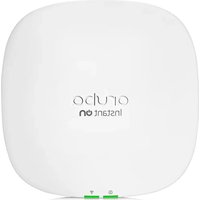

- HP MSM313/MSM323 INTEGRATED SERVICES ACCESS POINTS
- PUBLICATION NUMBER
- TRADEMARK CREDITS
- DISCLAIMER
- WARRANTY
- CONTENTS
- CHAPTER
- INTRODUCTION
- WORKING WITH VSCS
- WIRELESS CONFIGURATION
- NETWORK CONFIGURATION
- MANAGEMENT
- SECURITY
- USER AUTHENTICATION
- PUBLIC/GUEST NETWORK ACCESS
- LOCAL MESH
- MAINTENANCE
- APPENDIX A
- REGULATORY INFORMATION
- APPENDIX B
- RESETTING TO FACTORY DEFAULTS
- ABOUT THIS GUIDE
- PRODUCTS COVERED
- IMPORTANT TERMS
- CONVENTIONS
- MANAGEMENT TOOL
- COMMANDS AND PROGRAM LISTINGS
- WARNINGS AND CAUTIONS
- COMMON DEPLOYMENTS
- PUBLIC ACCESS DEPLOYMENT
- MULTIPLE HOTSPOTS WITH AAA SERVER
- ENTERPRISE DEPLOYMENT
- CONTACTING SUPPORT
- ONLINE DOCUMENTATION
- KEY CONCEPTS
- MANAGEMENT WITH VLANS
- WORKING WITH AUTONOMOUS APS
- VSC CONFIGURATION
- ABOUT ACCESS CONTROL AND AUTHENTICATION
- IF PROVIDE ACCESS CONTROL IS ENABLED
- IF PROVIDE ACCESS CONTROL IS DISABLED
- VSC CONFIGURATION OPTIONS
- ACCESS CONTROL
- VIRTUAL AP
- QUALITY OF SERVICE
- ALLOWED WIRELESS RATES
- VSC INGRESS MAPPING
- VSC EGRESS MAPPING
- DEFAULT USER DATA RATES
- WIRELESS PROTECTION
- WPA
- X
- WEP
- HTML-BASED USER LOGINS
- MAC-BASED AUTHENTICATION
- LOCATION-AWARE
- DHCP SERVER
- DHCP RELAY AGENT
- VSC DATA FLOW
- STAND-ALONE DEPLOYMENT: NON ACCESS-CONTROLLED VSC
- VSC ON SERVICE CONTROLLER
- INGRESS
- FEATURES
- EGRESS
- STAND-ALONE DEPLOYMENT: ACCESS-CONTROLLED VSC
- DEPLOYED WITH AN AUTONOMOUS AP: ACCESS-CONTROLLED VSC
- VSC ON AP
- USING MULTIPLE VSCS
- ABOUT THE DEFAULT VSC
- QUALITY OF SERVICE (QOS)
- QOS PRIORITY MECHANISM
- SVP SUPPORT
- P
- VSC-BASED PRIORITY
- DIFFERENTIAL SERVICES (DIFFSERV)
- TOS
- IP QOS
- DISABLED
- QOS EXAMPLE
- CREATING A NEW VSC
- WIRELESS COVERAGE
- WIRELESS MODE
- FACTORS LIMITING WIRELESS COVERAGE
- RADIO POWER
- ANTENNA CONFIGURATION
- INTERFERENCE
- PHYSICAL CHARACTERISTICS OF THE LOCATION
- CONFIGURING OVERLAPPING WIRELESS CELLS
- PERFORMANCE DEGRADATION AND CHANNEL SEPARATION
- SELECTING CHANNELS
- SAMPLE CHANNEL SELECTIONS
- DISTANCE BETWEEN APS
- AUTOMATIC POWER CONTROL
- CONDUCTING A SITE SURVEY
- SCANNING FREQUENCY
- IDENTIFYING UNAUTHORIZED ACCESS POINTS
- RADIO CONFIGURATION
- CONFIGURATION PARAMETERS
- OPERATING MODE
- CHANNEL
- INTERVAL
- TIME OF DAY
- AUTOMATIC CHANNEL EXCLUSION LIST
- DISTANCE BETWEEN ACCESS POINTS
- AVAILABLE SETTINGS
- RTS THRESHOLD
- MULTICAST TX RATE
- ANTENNA SELECTION
- BEACON INTERVAL
- SPECTRALINK VIEW
- MAXIMUM RANGE (ACK TIMEOUT)
- TRANSMIT POWER CONTROL
- MOBILITY
- PORT CONFIGURATION INFORMATION
- DEFAULT PORT SETTINGS
- BRIDGE PORT CONFIGURATION
- BRIDGE SPANNING TREE PROTOCOL
- PRIORITY
- BRIDGE PORT
- LAN PORT CONFIGURATION
- MANAGEMENT ADDRESS
- LINK SETTINGS
- INTERNET PORT CONFIGURATION
- ADDRESSING OPTIONS
- NETWORK ADDRESS TRANSLATION
- LIMIT NAT PORT RANGE
- ADDRESS ALLOCATION
- DHCP SERVER (GLOBAL)
- ADDRESSES
- START / END
- GATEWAY
- ADDRESS/MASK
- DNS SERVERS ASSIGNED TO CLIENTS
- SETTINGS
- DOMAIN NAME
- LEASE TIME
- LOGOUT HTML USER ON DISCOVERY REQUEST
- CIRCUIT ID
- REMOTE ID
- SERVER
- PRIMARY DHCP SERVER ADDRESS
- SECONDARY DHCP SERVER ADDRESS
- VLAN SUPPORT
- TYPES OF VLANS
- VSC-BASED VLANS
- GENERAL VLANS
- LAN PORT
- INTERNET PORT
- USER-ASSIGNED VLANS
- VLAN RANGES
- VLAN CONFIGURATION
- GENERAL
- ASSIGN IP ADDRESS VIA
- NAT
- GRE TUNNELS
- BANDWIDTH CONTROL
- INTERNET PORT DATA RATE LIMITS
- BANDWIDTH LEVELS
- ASSIGNING TRAFFIC TO A BANDWIDTH LEVEL
- CUSTOMIZING BANDWIDTH LEVELS
- EXAMPLE
- DNS
- DNS SERVERS
- DNS ADVANCED SETTINGS
- IP ROUTES
- CONFIGURATION
- ACTIVE ROUTES
- DEFAULT ROUTES
- PERSISTENT ROUTES
- PPTP CLIENT
- ABOUT PPTP CLIENT ROUTES (INTERNET PORT)
- ABOUT PPTP SERVER ROUTES (INTERNET PORT)
- NETWORK ADDRESS TRANSLATION (NAT)
- NAT SECURITY AND STATIC MAPPINGS
- NAT EXAMPLE
- ONE-TO-ONE NAT
- RIP
- CREATE THE PROFILES
- SELECT SAVE
- ASSIGN THE PROFILES TO A VSC
- IGMP PROXY
- MANAGEMENT SCENARIOS
- MANAGEMENT STATION
- STARTING THE MANAGEMENT TOOL
- CUSTOMIZING MANAGEMENT TOOL SETTINGS
- ADMINISTRATOR AUTHENTICATION
- AUTHENTICATING ADMINISTRATORS USING A RADIUS SERVER
- LOGIN CONTROL
- WEB SERVER
- AUTO-REFRESH
- SNMP
- CONFIGURING SNMP SETTINGS
- ATTRIBUTES
- AGENT
- TRAPS
- SOAP
- CONFIGURING THE SOAP SERVER
- SERVER SETTINGS
- SECURE HTTP (SSL/TLS)
- USING CLIENT CERTIFICATE
- HTTP AUTHENTICATION
- TCP PORT
- SECURITY CONSIDERATIONS
- CLI
- CONFIGURING CLI SUPPORT
- SECURE SHELL ACCESS
- SERIAL PORT ACCESS
- SYSTEM TIME
- COUNTRY
- SATELLITES
- USING A THIRD-PARTY RADIUS SERVER
- CONFIGURING A RADIUS CLIENT PROFILE ON THE SERVICE CONTROLLER
- CONFIGURATION PROCEDURE
- PROFILE NAME
- PRIMARY/SECONDARY RADIUS SERVER
- AUTHENTICATION REALMS
- IMPORTANT
- CONFIGURING GLOBAL 802.1X SETTINGS
- FIREWALL
- FIREWALL PRESETS
- FIREWALL CONFIGURATION
- CUSTOMIZING THE FIREWALL
- CREATING VPN CONNECTIONS
- CAUTION: THE VPN TUNNEL SHOULD NOT BE USED TO TRANSPORT USER TRAFFIC. THE TUNNEL SHOULD ONLY BE USED TO CARRY MANAGEMENT TRAFFIC (RADIUS, SNMP, AND MANAGEMENT SESSIONS)
- CONFIGURATION SETTINGS
- CONNECTION
- PPTP SERVER ADDRESS
- DOMAIN NAME(S)
- AUTO-ROUTE DISCOVERY
- LCP ECHO REQUESTS
- ACCOUNT
- USERNAME
- PASSWORD / CONFIRM PASSWORD
- IPSEC
- IPSEC VLAN MAPPING
- IPSEC SECURITY POLICY DATABASE
- ADDING A NEW SECURITY POLICY
- GENERAL SETTINGS
- PEER INFORMATION
- AUTHENTICATION METHOD
- SECURITY POLICY
- MANAGING CERTIFICATES
- TRUSTED CA CERTIFICATE STORE
- ISSUED TO
- CURRENT USAGE
- CRL
- DELETE
- INSTALLING A NEW CA CERTIFICATE
- CA CERTIFICATE IMPORT FORMATS
- DEFAULT CA CERTIFICATES
- CERTIFICATE AND PRIVATE KEY STORE
- ISSUED BY
- INSTALLING A NEW PRIVATE KEY/PUBLIC KEY CERTIFICATE CHAIN PAIR
- DEFAULT INSTALLED PRIVATE KEY/PUBLIC KEY CERTIFICATE CHAINS
- CERTIFICATE USAGE
- SERVICE
- AUTHENTICATE TO PEER USING
- NUMBER OF ASSOCIATED CAS
- CHANGING THE CERTIFICATE ASSIGNED TO A SERVICE
- ABOUT CERTIFICATE WARNINGS
- IPSEC CERTIFICATES
- IPSEC — TRUSTED CA CERTIFICATES
- IPSEC — MANAGE CA CERTIFICATES
- IPSEC — LOCAL CERTIFICATE STORE
- IPSEC — MANAGE LOCAL CERTIFICATE
- IPSEC — X.509 CERTIFICATE REVOCATION LIST
- IPSEC — MANAGE CERTIFICATE REVOCATION LIST
- AUTHENTICATION SUPPORT
- AUTHENTICATION TYPES
- WPA / WPA2 AND 802.1X AUTHENTICATION
- GLOBAL MAC
- VSC-BASED MAC
- HTML-BASED AUTHENTICATION
- NO AUTHENTICATION
- USING MORE THAN ONE AUTHENTICATION TYPE IN A VSC
- AUTHENTICATION EXAMPLES
- MAC AND 802.1X ENABLED, MANDATORY 802.1X AUTHENTICATION DISABLED
- MAC AND 802.1X ENABLED, MANDATORY 802.1X AUTHENTICATION ENABLED
- MAC DISABLED AND 802.1X ENABLED, MANDATORY 802.1X AUTHENTICATION DISABLED
- MAC DISABLED AND 802.1X ENABLED, MANDATORY 802.1X AUTHENTICATION ENABLED
- FILTERS
- LOCAL USER LIST
- CURRENT USERS
- NEW USER
- PASSWORD/CONFIRM PASSWORD
- IDLE TIMEOUT
- SESSION TIMEOUT
- CONCURRENT SESSIONS
- TIP: FOR DETAILED INFORMATION ON CONFIGURING THE PUBLIC ACCESS INTERFACE, SEE THE HP MSM313/MSM323 NETWORK ACCESS CONFIGURATION GUIDE
- GLOBAL ACCESS CONTROL SETTINGS
- CLIENT OPTIONS
- LOCATION CHANGE NOTIFICATION
- NOC AUTHENTICATION
- SERVICE CONTROLLER PORTS
- LOCATION CONFIGURATION
- RETRIEVE ATTRIBUTES USING RADIUS
- CONFIGURED ATTRIBUTES
- NEW IN THIS RELEASE
- BENEFITS
- LOCAL MESH TERMINOLOGY
- OPERATIONAL MODES
- NODE DISCOVERY
- OPERATING CHANNEL
- LOCAL MESH PROFILES
- CONFIGURING A LOCAL MESH PROFILE
- ENABLED/DISABLED
- LINK NAME
- USE
- SPEED
- TKIP
- AES/CCMP
- ADDRESSING
- STATIC
- REMOTE MAC ADDRESS
- LOCAL MAC ADDRESS
- DYNAMIC
- MODE
- MESH ID
- MINIMUM SNR
- SNR COST PER HOP
- ALLOWED DOWNTIME
- MAXIMUM LINKS
- INITIAL DISCOVERY TIME
- PROMISCUOUS MODE
- PRESERVE MASTER LINK ACROSS REBOOTS
- ALLOW FORCED LINKS
- UPDATE MESH ID FROM SERVER
- RESTART DISCOVERY
- CONFIGURATION CONSIDERATIONS
- SINGLE RADIO VS. MULTIPLE RADIOS
- SIMULTANEOUS AP AND LOCAL MESH
- USING TWO RADIOS FOR LOCAL MESH
- USING 802.11A FOR LOCAL MESH
- MAXIMUM RANGE
- CONFIGURATION SUMMARY
- SAMPLE LOCAL MESH DEPLOYMENTS
- RF EXTENSION
- BUILDING-TO-BUILDING CONNECTIONS
- DYNAMIC NETWORKS
- CONFIG FILE MANAGEMENT
- MANUAL CONFIGURATION FILE MANAGEMENT
- BACKUP CONFIGURATION
- RESET CONFIGURATION
- RESTORE CONFIGURATION
- SCHEDULED OPERATIONS
- MANAGING THE CONFIGURATION FILE WITH CURL
- UPLOADING THE CONFIGURATION FILE
- DOWNLOADING THE CONFIGURATION FILE
- RESETTING THE CONFIGURATION TO FACTORY DEFAULTS
- FIRMWARE UPDATES
- IMMEDIATE UPDATE
- SCHEDULED UPDATE
- FIRMWARE DISTRIBUTION
- OPTIONALLY EDIT THE DISTRIBUTION LIST
- A
- USA: FEDERAL COMMUNICATIONS COMMISSION (FCC)
- CAUTION! EXPOSURE TO RADIO FREQUENCY RADIATION
- INTERFERENCE STATEMENT
- CANADA: INDUSTRY CANADA (IC)
- EUROPE
- IMPORTANT NOTICE
- INFORMATION FOR THE USER
- HEALTH INFORMATION
- MSM313/MSM
- EUROPEAN DIRECTIVES AND EUROPEAN STANDARDS
- NORTH AMERICAN STANDARDS
- USING THE RESET SWITCH
- USING THE MANAGEMENT TOOL
- USING SPECIAL COMMANDS
Brand : HP
Model : ProCurve MSM313
Category : Access Point