
Aruba Instant On AP22 - Access Point HP - Free user manual and instructions
Find the device manual for free Aruba Instant On AP22 HP in PDF.


| Product Type | Wireless Access Point |
| Model | Aruba Instant On AP22 |
| Brand | HP |
| Dimensions (W x D x H) | 160 mm x 160 mm x 40 mm |
| Weight | 0.5 kg |
| Mounting Type | Wall or ceiling |
| Ethernet Ports | 1 x 1 GbE RJ-45 (PoE in) |
| Power Supply | PoE (802.3af) or 12V DC |
| Wi-Fi Standard | IEEE 802.11ax (Wi-Fi 6) |
| Frequency Bands | 2.4 GHz and 5 GHz |
| MIMO Configuration | 2x2 MU-MIMO |
| Bluetooth | Bluetooth 5.0 |
| Management | Aruba Instant On cloud-based or local web |
| Security | WPA3, WPA2, AES |
| Operating Temperature | 0°C to 40°C |
| Ingress Protection | IP30 (indoor only) |
| Recommended Users | Up to 25 concurrent clients |
| Power Consumption | 12W max |
| Care Instructions | Wipe with a dry cloth; avoid liquids |
| Safety Certifications | CE, FCC, IC |
| Spare Parts | No user-replaceable parts; mounting kit available separately |
| Repairability | Not user serviceable; contact support |
Frequently Asked Questions - Aruba Instant On AP22 HP
User questions about Aruba Instant On AP22 HP
0 question about this device. Answer the ones you know or ask your own.
Ask a new question about this device
Download the instructions for your Access Point in PDF format for free! Find your manual Aruba Instant On AP22 - HP and take your electronic device back in hand. On this page are published all the documents necessary for the use of your device. Aruba Instant On AP22 by HP.
USER MANUAL Aruba Instant On AP22 HP
Aruba Instant On 2.2.0 User Guide
WEB APPLICATION VERSION
aruba
Instant On
Copyright Information
© Copyright 2020 Hewlett Packard Enterprise Development LP.
Open Source Code
This product includes code licensed under the GNU General Public License, the GNU Lesser General Public License, and/or certain other open source licenses. A complete machine-readable copy of the corresponding source code is available upon request. This offer is valid to anyone in receipt of this information and shall expire three years following the date of the final distribution of this product by Hewlett Packard Enterprise Company. To obtain such source code, send a check or money order in the amount of US $10.00 to:
Hewlett Packard Enterprise Company
6280 America Center Drive
San Jose, CA 95002
USA
Contents .. 3.
Revision History...5.
About this Guide 6
Intended Audience...6.
Related Documents...6.
Contacting Support...6.
Aruba Instant On Solution...7
Key Features 7
Supported Devices...7.
Whats New in this Release
New Features and Hardware Platforms.
9
9
Aruba Instant On Deployment Concepts
Wireless Deployment—Access Point Only
Wired Deployment—Switch Only
Wired and Wireless Deployment—Access Point and Switch
11
11
11
Provisioning your Aruba Instant On Devices
Downloading the Mobile App.
Setting Up Your Wireless Network
AP Configuration Modes
Local Management for Switches
IP Assignment for Access Points
Discovering Available Devices.
Deploying Multicast Shared Services
Accessing Aruba Instant On Application
Managing Sites Remotely.
13
3
14
16
17
19
20
22
23
25
Aruba Instant On User Interface.
Using the Instant On User Interface
Site Management 28
About Software 30
Monitoring Site Health
Alerts 32
Viewing and Updating Inventory
Adding a Device 34
Types of Devices 35
Extending your Network 35
Radio Management 37
Access Point Lights 37
Loop Protection 37 Power Schedule 38 DNS 39 Access Point Details 39 Router Details 41 Switch Details 45 Topology 51 Auto-Detection and Auto-Configuring of Switch Ports 54
Configuring Networks...55
Employee Network 55
Guest Network 62
Wired Network 72
Analyzing Application Usage 77
Viewing Application Information 80
Viewing and Blocking Application Access 82
Managing Clients 83
Viewing Clients in the Site 83
Viewing Client Details 85
Wired Clients 87
Managing Your Account 89
Modifying Administrator Account Information 89
Notifications 89
Managing AP Firmware Upgrades 91
Upgrading the Firmware for an Instant On AP or Switch 91
Instant On Image Server 91
Updating the Software Image on an Instant On Site 91
Verifying Client Connectivity During Upgrade 92
Troubleshooting 93
The following table lists the revisions of this document.
Table 1: Revision History
| Revision Change Description | |
| Revision 01 Initial release. | |
This User Guide describes the features supported by Aruba Instant On 2.2.0 and provides instructions for setting up and configuring the Instant On network.
Intended Audience
This guide is intended for administrators who configure and use Instant On APs.
Related Documents
In addition to this document, the Aruba Instant On 2.2.0 product documentation includes the
■ Aruba Instant On Access Point Hardware Documentation ■ Aruba Instant On Release Notes ■ Aruba Instant On 1930 Switch Series Management and Configuration Guide ■ Aruba Instant On 1930 Installation and Getting Started Guide
Contacting Support
Table 2: Contact Information
| Main Site arubainstanton.com | ____ |
| Support Site support.arubainstanton.com | ____ |
| Instant On Social Forums and Knowledge Base | community.arubainstanton.com |
| North American Telephone 1-800-943-4526 (Toll Free)1-408-754-1200 | |
| International Telephone community.arubainstanton.com/t5/Contact-Support/ct-p/contact-support | |
| EULA | https://www.arubainstanton.com/eula/ |
| Security Incident Response Team | Site:arubanetworks.com/support-services/security-bulletins/Email:aruba-sirt@hpe.com |
The Instant On Solution is a simple, fast, and secure solution designed for small businesses. It is an affordable and easy-to-use solution that is ideal for businesses with simple technology requirements and setups that do not have IT staff. The product offers the very latest Wi-Fi technologies, so that your business can have a fast experience even in a busy office or store. The Instant On mobile app and web application in the Instant On Solution suite enable provisioning and managing your networks. Instant On offers the following benefits:
■ Mobile app and web application based quick setup and faster network bring-up ■ Ease of use and right-sized feature set ■ Simple statistics to view the network health and usage ■ Remote monitoring capabilities ■ Simple troubleshooting
Key Features
The key features introduced as part of the Aruba Instant On web application are:
■ Monitoring Site Health ■ Configuring Networks ■ Analyzing Application Usage ■ Managing Clients ■ Managing Sites Remotely
Supported Devices
Aruba Instant On currently supports the following Devices:
Indoor Instant On Access Points
■ Aruba Instant On AP11 Access Points ■ Aruba Instant On AP11D Access Points ■ Aruba Instant On AP12 Access Points ■ Aruba Instant On AP15 Access Points ■ Aruba Instant On AP22 Access Points
Outdoor Instant On Access Points
■ Aruba Instant On AP17 Access Points
For more information on the currently supported Aruba Instant On hardware and how to purchase Instant On solution, see:
■ Aruba Instant On Hardware Documentation ■ Buy Now from a Local Reseller
Instant On Switches
■ Aruba Instant On 1930 8G 2SFP Switch ■ Aruba Instant On 1930 8G Class4 PoE 2SFP 124W Switch ■ Aruba Instant On 1930 24G 4SFP/SFP+ Switch ■ Aruba Instant On 1930 24G Class4 PoE 4SFP/SFP+ 195W Switch ■ Aruba Instant On 1930 24G Class4 PoE 4SFP/SFP+ 370W Switch ■ Aruba Instant On 1930 48G 4SFP/SFP+ Switch ■ Aruba Instant On 1930 48G Class4 PoE 4SFP/SFP+ 370W Switch
This section lists the new features, enhancements, and hardware platforms introduced in Aruba 2.2.0.
New Features and Hardware Platforms
Instant On WLAN Features
Table 3: New Features for WLAN Deployments in Instant On 2.2.0
| Feature Description | |
| Cloudflare DNS Integration and DNS settings | Cloudflare DNS is the default DNS server for Instant On networks. A new DNS settings page is also introduced in the Inventory page enable configuration of DNS servers. |
| Configuring Bandwidth Usage Limit an Entire Network | on A new option is added to allow users to configure a bandwidth per AP network, rather than limiting the usage for each client. |
| Email Notifications An option to enable email notifications for the alerts received on the site is now available in the Instant On web application. | |
| Enabling Optimization for Video Streaming | A new option is added to enhance the quality of video converting multicast traffic into unicast traffic on a wireless network |
| Enhancements to Shared Services | The following enhancements to shared services are introduced in this release:■ Two new shared services are added.■ The shared services are displayed per devices instead of per service.■ A multiple services icon is displayed next to the device, if i provides more than one service.■ New services for known devices are automatically added. |
| Increase in the Number of Administ Accounts | Your can configure up to 3 administrator accounts to manage the using the Instant On web application. |
| New Software Available Alert A new informational alert is added when a new software update is available for installation on the Instant On network. | |
| Wi-Fi Enhanced Open (OWE) | A new option is added to enable OWE on Guest networks, configured with Open or Portal Security type. |
Instant On Wired Features
Table 4: New Features for Wired Deployments in Instant On 2.2.0
| Feature Description | |
| Port Security - Client Allow List | This feature allow lists clients and devices connected to a particular port and blocks other clients and devices. |
| Configuring Schedule for PoE Supply | The power schedule feature allows you to configure a time range during which a switch or PoE capable device supply PoE power to connected to its ports. |
| Configuring Voice Network Enabling the Voice network checkbox on the wired network VLAN at the clients with voice capabilities to be automatically redirected network. | |
| Energy Efficient Ethernet | Instant On supports a subset of the EEE function (802.3az) that reduces power consumption on switch ports when data activity is low |
| Power Management for Ports The power management settings for ports allows you to configure supply policies for PoE powered devices connected to the swi | |
| Routing on Instant On Switches | Instant On switches support IP routing between wired networks. |
| Topology View of Network Devices | A topology chart of the network is added to the Inventory information regarding the link states, devices connected, and th of clients connected to a particular device. The device settings device can be accessed by clicking on a device. |
The Instant On Solution currently supports three types of deployments, namely:
■ Wireless Deployment—Access Point Only ■ Wired Deployment—Switch Only ■ Wired and Wireless Deployment—Access Point and Switch
During the initial setup, you need to select one of the above deployment modes based on network you want to create.
Wireless Deployment—Access Point Only
The wireless deployment mode is suitable for users whose network infrastructure would mainly consist of Instant On access points. You begin to create your site by powering on your Instant On APs and connecting them to the internet. A choice is presented to configure the APs in a private or router-based setup. The network you create when you go through the initial setup will be the default network for your site and cannot be deleted. The SSID of this default network will be read-write and can be modified as deemed necessary. However, the management VLAN assigned to this default network is read-only and cannot be modified. Once you have completed the initial setup, you can choose to expand your network using additional APs or switches. In this deployment, you are allowed to create new wireless networks on a site. For more information, see Setting Up Your Wireless Network.
Wired Deployment—Switch Only
The wired deployment mode is suitable for users whose network infrastructure is focused mainly on onboarding of Instant On switches. The initial setup using the Instant On mobile app or web interface will guide you through a step-by-step process of onboarding your switch. The switch must be powered on and connected to the internet to complete the onboarding process. A wired network is created during initial setup and will serve as the default network for the site and cannot be deleted. Unlike wireless networks, the wired network will not require you to create an SSID and password for the network. The network name is retained as the wired network name and a default management VLAN ID is set during setup. At a later point in time, you can choose to add Instant On APs to the site by extending your network and following the process of creating a wireless SSID. In this deployment, you are allowed to create up to 22 wired networks on a site. For more information, see Setting Up Your Wired Network.

If there are any Instant On APs powered on and ready in the network, they will be discovered during setup and added to the network along with the switch.
Wired and Wireless Deployment—Access Point and Switch
The wired and wireless deployment is suitable for users whose network infrastructure includes a mix of wired Instant On switches and wireless Instant On APs. The initial setup is similar to that of a wireless network, where you are presented with two choices to either connect your APs in a private or router-based setup. In this deployment, you are allowed to create a maximum of 30 networks (8 wireless) on a site. There are 2 types of scenarios involved when deploying AP and switch:
network, where you are presented with two choices to either connect your APs in a private router-based setup. In this deployment, you are allowed to create a maximum of 30 networks (8 wireless) on a site. There are 2 types of scenarios involved when deploying AP and switch.
■ Deploying an AP and a Switch in Private Network Mode ■ Deploying an AP and a Switch in Router Mode
When you begin creating a new site, select the Access point and switch radio button from the Getting started screen and click Continue. Now follow the instructions provided in the AP Configuration Modes section to onboard your devices based on the preferred mode.
This chapter describes the following procedures:
■ Downloading the Mobile App ■ Setting Up Your Wireless Network ■ AP Configuration Modes ■ Discovering Available Devices ■ Accessing Aruba Instant On Application ■ Managing Sites Remotely
Downloading the Mobile App
The Aruba Instant On mobile app enables you to provision, manage, and monitor your network. To start using the Instant On mobile app, perform the following actions:
- Download the app on your smartphone
■ To install the app on iPhone, go to Apple App Store and search for Aruba Instant On. ■ To install the app on Android phones, go to Google Play Store and search for Aruba Instant On.
- Launch the Instant On application and follow the on-screen instructions to complete the
Alternatively, you may choose to complete the setup on a web browser using the Instant O For more information, see Accessing Aruba Instant On Application.
Mobile OS Requirements
The following mobile OS versions support the Aruba Instant On 2.2.0 mobile app:
■ Android 7 or later versions ■ iOS 11 or later versions
Setting Up Your Wireless Network
The Instant On Solution requires you to connect Aruba Instant On APs to your wired netwo internet connectivity.
Table 5: Instant On Wireless Network Provisioning
| SL No | Steps | Illustration |
| 1. Private Network Mode—Power on the Aruba Instant On AP using the power adapter or using a Power over Ether (PoE) port on a PoE capable switch, that the AP is connected to your no using an Ethernet cable (included in box). |  | |
| Router Mode—Connect the E0/PT or ENET port of the Instant On device as a primary Wi-Fi router to the ISP provided modem using an Ethernet cable. | ||
| 2. Verify the LED indicators to check if the is successfully connected to your provisioning network and is ready for to configure. The LED indicator starts blinking alternatively between green an amber. |  | |
| 3. Configure the Instant On AP using the v application. For more information, see Accessing Aruba Instant On Application. As an alternative, you may choose to download the mobile app on your A or iOS device. For more information, Downloading the Mobile App. |  | |
| 4. Launch the Instant On web or mobile application and follow the on-screen instructions to complete the setup. |  | |
 | ||
Setting Up Your Wired Network
The following procedure is a step-by-step process of the initial setup to onboard Aruba Instant a site:
Table 6: Instant On Wired Network Provisioning
| SL No | Steps | Illustration |
| 1. Ensure that the Instant On switch is connected to the internet to be disc |  | |
| 2. Connect the port you want to use as y switch uplink to your local network u an Ethernet cable, then power it on. NOTE: If you have more than one I On switch, you will be able to add later on. | 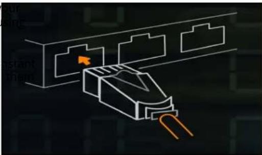 | |
| 3. Power on the switch. The switch will be ready to be discovered when the do LED light alternates between green and amber. For more information, see Clo LED and AP LED Light Status |  | |
| 4. Download the mobile app on your Andro or iOS device. For more information, Downloading the Mobile App. As an alternative, you may choose to configure the Instant On switch using web application. For more information, Accessing Aruba Instant On Application. |  | |
| 5. Launch the Instant On web or mobile application and follow the on-screen instructions to complete the setup. |  | |
The following table displays the various LED statuses you might see when onboarding Instant On switches to a site:
Table 7: Cloud LED and AP LED Light Status
| Switch Cloud LED or AP LED Status | |
| No Lights Indicates that the device | has no power. Review the different power options and verify that the cables are properly connected. |
| Blinking Green Indicates that the device is booting or upgrading. It can take up to 8 minutes for the device to be ready. | |
| Solid Amber Indicates that the device has detected a problem. Click or Tap the Troubleshoot link to learn more. | |
| Alternate Green and Amber Indicates that the device is ready to onboard. | |
| Solid Green Indicates that the device is connected and configured. | |
| Blinking Amber Indicates that the identification of the device has been turned ON. NOTE: This applies only to Instant On access points and switches. | |
| Solid Red Indicates that the device has an issue. Unplug and replug the device to restore connectivity. Contact support if the issue persists. NOTE: This applies only to Instant On access points and switches. | |
AP Configuration Modes
Before you begin to add devices to a site during the initial setup, you must decide the mode in which the APs should be deployed in the network. Aruba Instant On currently supports the following modes in which your Instant On access points can be deployed:
■ Private Network Mode
- Router Mode
Private Network Mode
The Instant On devices will be part of a private network behind a gateway or a firewall before reaching the internet. Use this mode if you already have a local network infrastructure in place that includes a DHCP server as well as a gateway or a firewall to the Internet.
Pre-Requisites
Before you begin to provision your Instant On AP, ensure that the following pre-requisites are adhered to:
■ A working internet connection. ■ A switch that is connected to the Internet gateway or modem. - A DHCP server to provide IP addresses to the clients connecting to the Wi-Fi network. The DHCP server may be offered by the switch or the Internet gateway. This does not apply if you are configuring the network in NAT mode. ■ TCP ports 80 and 443 and UDP port 123 should not be blocked by a firewall. ■ The Instant On APs must be powered on and have access to the internet.
Configuring Your Instant On Devices in Private Network Mode
Follow these steps to add your Instant On devices to the network in private mode:
- Connect the E0/PT or ENET port of the Instant On devices to your local network using cable.
- Power on the Instant On devices. Alternatively, you can power on the devices using an Ethernet (PoE) switch or a power adapter.
- Observe the LED lights on the Instant On devices. It may take up to 10 minutes for them to upgrade their firmware and boot up. The devices will be ready to be discovered on the mobile app when the LED lights are alternating between green and amber.
- Enable location and Bluetooth services and set the Aruba Instant On app permissions to use location and Bluetooth services in order to automatically discover nearby Instant On devices.
- Review and add the devices to your network.
Router Mode
In Router mode, an Instant On device will be connected directly to a modem supplied by your Internet Service Provider (ISP) and it will be your primary Wi-Fi router in the network. In this mode, the device will offer DHCP, gateway, and basic firewall services for your network. The Instant On app provisions the device to configure and establish a PPPoE connection with the ISP.
Pre-Requisites
Before you begin to provision your Instant On AP as a primary Wi-Fi router, ensure that the following prerequisites are adhered to:
■ A working internet connection provided by your Internet Service Provider (ISP). ■ TCP ports 80 and 443 and UDP port 123 should not be blocked by a firewall. ■ The Instant On AP must be directly connected to the internet modem with no other device in between. It must therefore be the only AP connected to the internet. Other APs have to be powered on and added later through mesh using the extend network capability.
Configuring Your Instant On Device in Router Mode
Follow these steps to add your Instant On devices to the network in router mode:
- Connect the E0/PT or ENET port of the Instant On device acting as a primary Wi-Fi router to the modem using an Ethernet cable.
- Power on the primary Wi-Fi router.
- Observe the LED lights on the primary Wi-Fi router. It may take up to 10 minutes for it to upgrade its firmware and boot up. The router will be ready to be discovered on the mobile app when the LED lights are alternating between green and amber.
- Enable location and Bluetooth services on your mobile device and set the Aruba Instant On app permissions to use location and Bluetooth services in order to automatically discover nearby Instant On devices.
Local Management for Switches
The Aruba Instant On switches can also be managed using the local WebUI of the switch. This is when the switch is in its factory default state and connected to the internet.

The following procedure describes how to access the local WebUI of the switch:
- Type the IP address of the switch in your web browser and press enter. The landing WebUI is displayed.
- Click the CONNECT tab in the For Local Management side of the landing page.
The switch cannot be onboarded or managed from the Instant On web interface once the local management of the switch is selected. The switch needs to be reset to factory default from the local WebUI to switch management mode.
If you had opted to manage the switches using the cloud mode earlier (Instant On web app) and want to switch to the local WebUI:
- Click the Inventory ( ) tile on the Aruba Instant On home page or click the Site Health ( ) banner and then click on Show inventory.
- Click the (>) arrow next to a switch in the Inventory list and then click Actions tab.
- Select Switch to local management. Selecting this option will remove the switch and its configuration from the inventory.
Switch Provisioning Using the Local WebUI
The local WebUI provides an option to configure a static IP on the Instant On switch. The default IP address is from the DHCP server. The following procedure configures a static IP address and IP addressing information on the switch using the local WebUI:
- In the local WebUI, click the Change network connectivity link at the bottom of the page.
- Under IP addressing, select the Static radio button.
- Enter the IP address, Netmask, Gateway IP, and DNS information.
- Click Apply.
The following procedure configures a management VLAN for the switch using the local WebUI:

- Under Management VLAN, select the Tagged on uplink port radio button.
- Enter the Management VLAN ID and the Uplink port ID.
- Click Apply.
IP Assignment for Access Points
The IP address for the access point can be assigned using the local WebUI during onboarding. The following procedure describes how to assign an IP address for the access point using the
- Connect the AP to the network.
- Once the LED on the AP becomes solid orange, the AP will broadcast an open SSID II AB:CD:EF approximately after one minute, where AD:CD:EF corresponds to the last three octets of the MAC address of the AP.
- Connect your laptop or mobile device to the SSID and access the local web server at https://connect.arubainstanton.com. The local WebUI configuration page is displayed.
- In the IP addressing section, configure either of the following options to assign an IP address for the access point:
a. Automatic (default): The DHCP server assigns an IP address for the access point. This option is selected by default. b. Static: To define a static IP address for the access point, specify the following parameters:
i. IP address—IP address for the access point. ii. Subnet mask—Subnet mask. iii. Default gateway—IP address of the default gateway. iv. DNS server—IP address of the DNS server.
c. PPPoE: The ISP assigns an IP address for the access point. This option is configurable only on AP11D access points when it is functioning as the primary router for the network. For information on configuring PPPoE, see Setting Up WAN Connectivity for Your Network.
- Click Apply. The AP will restart after the configurations are applied.
The IP assignment settings can be seen in the Connectivity tab of AP Details and Router Details page for APs and routers respectively.
Setting Up WAN Connectivity for Your Network
PPPoE configuration is possible only when the Instant On AP is connected as a primary Wi-Fi. This must be done before onboarding Instant On AP(s). The local web server on the device will offer only when the Instant On AP is in its factory default state and not if a DHCP address was assigned. Once the AP is connected to the cloud, the PPPoE configuration will not be available for modifications. However, if the AP loses connectivity to the cloud and PPPoE failures are detected, you can access the WebUI and update the settings again.

Follow the steps below to configure PPPoE on your network:
- The Instant On AP should be connected to the ISP provided modem but does not have an IP address provided by the DHCP server.
- Once the LED on the AP becomes solid orange, the AP will broadcast an open SSID II AB:CD:EF approximately after one minute, where AB:CD:EF corresponds to the last three octets of the MAC address of the AP.
- Connect your laptop or mobile device to the SSID and access the local web server through https://connect.arubainstanton.com. The local WebUI configuration page is displayed.
- Under IP addressing, select the PPPoE radio button.
- Enter the PPPoE Username, Password and MTU provided by your ISP, in the respective fields.
- Click Apply. The AP will reboot once the PPPoE configuration is applied.
- Wait for the LED lights to flash green and orange. This indicates that the PPPoE link is established. You will see the device onboarding status now reads "Waiting to be onboarded..". This step might take an additional five minutes, if the AP upgrades its firmware during the reboot process.
- You can now proceed to creating a new site and adding devices. For more information, see the section below.
■ Setup a New Site using the Web Application

If an AP with the PPPoE configuration is removed from the Inventory or the site is deleted, the AP will return to factory default state and the PPPoE configuration will be erased from the AP.
Discovering Available Devices
There are multiple ways to add an Instant On AP and switches to a site during the initial setup. Choose any of the following methods to add devices for the first time and complete the setup.
■ BLE Scanning—The Instant On mobile app or web application scans for nearby devices through BLE and displays the discovered APs on the screen. Tap or click the Add devices button to add the discovered devices to the site. Alternatively, click Search again if there are more devices to be displayed. If the BLE scanning fails to discover any devices in the vicinity, tap the Add devices manually tab and choose to add devices to your network by entering the serial number or by scanning the barcode. - Serial Number—Enter the serial number located at the back of your Instant On AP or switch and click Add device.
■ Barcode Scanning—As an alternative to manually entering the serial number to add devices, tap the barcode scan icon on the mobile app and scan the barcode at the back of your Instant On device.
BLE Troubleshooting
BLE troubleshooting happens automatically during the auto-detection of APs in the initial setup. If any issues are detected, you will see a message in the mobile app that helps you troubleshoot any network-related issues and complete the network setup successfully.
Multiple Sites
When you log in to the Aruba Instant On application using your administrator account credentials, the My Sites page is displayed if multiple Aruba Instant On sites are registered to your account. To view or manage the settings of a particular site, click on any of the registered sites listed on this page.
Account Management
To navigate to the Account Management page, click the icon next to your account name in the page header and select Account management from the drop-down menu. The alphabet in the icon will change based on the first letter of your registered email account. For more information, refer to Managing Your Account.
Setup a New Site
To register a new Instant On site to your account:
- Click on the site name and select Setup a new site from the drop-down list. You will be redirected to the initial setup page.
- Follow the instructions given in Setting Up Your Wireless Network to add a new Instant On site.
Sign Out
Click on Sign out to sign out from your Aruba Instant On account.
Click the button in the page header to view help options. The following options to access support are available:
■ Help—Opens the Aruba Instant On documentation portal. For more information, see https://www.arubainstanton.com/techdocs/en/content/home.htm. ■ Support—The following options are available to reach Aruba Instant On support:
Contact support - Opens the Aruba Instant On Support Portal, which provides information about warranty and support policy for the product you selected and also the on-call technical support. For more information, see https://www.arubainstanton.com/contact-support/.
Support resources—Allows you to generate a support ID by clicking on the Generate Support ID button. The ID is then shared with Aruba Support personnel to run a diagnosis on your
■ Community - Provide a place for members or participants to search for information, read and post about topics of interest, and learn from each other. For more information, see https://community.arubainstanton.com/. ■ Technology partners & promotions - Provides details on the product, how it works, link to the support, and community page. For more information see https://www.arubainstanton.com/.
■ About - Provides information about the software currently installed on the web application, and also the following information:
- End User License Agreement
- Data Privacy Policy and Security Agreement
Deploying Multicast Shared Services
The Instant On solution supports a variety of multicast shared services, which are typically used for streaming of content from a phone, tablet or laptop to a connected TV or speakers.
The devices and multicast services can be discovered and accessed by both wired and wireless clients on the network VLAN ID. For more information, see Shared Services.
Multicast services can be configured in one of the following modes:
Private Network Mode
To detect services available on the same network (Same VLAN):
■ The networks can be configured either as employee network or guest network.
■ Devices offering the service and clients using the service must be connected to the same Wi-Fi Network or different networks with same VLAN ID.
- The IP and network Assignment settings must be set to Same as local network (default). You can assign a different network if required by your local network. For information on IP and network assignment, see IP and Network Assignment.
■ The Network Access setting can be set to Unrestricted access. For more information, see Network Access.

You can also configure Network Access setting to Restricted access to use the service offered by devices but need to specify the IP address.
To detect services available on the other networks (Cross VLAN):
■ The networks must be configured as an Employee network. ■ Devices offering the service and clients using the service can be connected to other employee networks with the different VLAN ID. - The IP and network assignment settings must be set to Same as local network (default). For information, see IP and Network Assignment. ■ The Network Access setting of employee network must be set to Unrestricted access. The clients connected to guest network can use shared services from employee network when its network set to Unrestricted access, IP and network assignment settings is set to Same as local network and service is allowed to access. In the case of guest network, services available on other networks can be detected. For more information, see Network Access.

Multicast services on Guest networks or Employee networks configured with the option Specific to this network are not supported if devices offering the service and clients using the service are located on different VLAN.
You can also configure Network Access setting to Restricted access to use the service offered by devices but need to specify the IP address.
Router Mode
To detect services available on the same network (Same VLAN):
■ The networks can be configured either as employee network or guest network. ■ Devices offering the service and clients using the service must be connected to the same Wi-Fi Network or different networks with same VLAN ID. ■ The IP and network Assignment settings must be set to Same as local network (default). You can assign a different network if required by your local network. For information on IP and network assignment, see IP and Network Assignment.
■ The Network Access setting must be set to Unrestricted access. For more information, see Network Access.
■ Alternatively, if an AP11D is used as the primary Wi-Fi router, the clients and services connected to ports E1, E2, E3 are also supported. In the case of wired network, the cross-VLAN services will be accessible.
To detect services available on the different networks (Cross VLAN):
■ The network must be configured as employee network. ■ Devices offering the service and clients using the service can be connected to other employee networks with a different VLAN ID. ■ The IP and network assignment settings must be set to Same as local network (default). For more information, see IP and Network Assignment. ■ The Network Access setting of employee networks must be set to Unrestricted access (default). The clients connected to guest network can access shared services from employee network when access is set to Unrestricted access and IP and network assignment settings is set to Same as local network. For more information, see Network Access.
Multicast services on Guest Networks or located on the WAN uplink are not supported.
Examples
Following are some of the examples for deploying multicast services:
■ Private network mode with a combination of wired and wireless clients and services. ■ Router mode with clients and services on same wireless network. ■ Router mode with clients and services on same wired network.
Accessing Aruba Instant On Application
Ensure that your system meets the following device OS and browser requirements to access web application.
Browser Requirements
The following versions of the web browsers support the Instant On web application:
■ Google Chrome ■ Mozilla Firefox ■ Microsoft Edge ■ Apple Safari
Create an Instant On Account
Follow these steps to create an Instant On account:
- Open a browser.
- Type https://portal.arubainstanton.com in the address bar and press the Enter key.
- Click Sign up to create a new Instant On account.
- Enter an email ID in the Email field. The email ID should not be associated with another Instant On account.
- Enter a password in the Password field.
- Select the End User License Agreement and Data Privacy Policy and Security Agreement checkbox.
- Click Create account.
- A verification email is sent to your email account. Follow the instructions in the email to verify your Instant On account.

The email notification with the verification link might sometimes end up in the junk email folder of your inbox.
- Once the above steps are complete, click Continue on the web application. You have now successfully registered an Instant On account.
You can use the same account credentials to sign in to the mobile app, web application, and support site.
Logging in to Instant On
To log in to the Instant On application, launch the Aruba Instant On web application.
- Open a browser.
- Type https://portal.arubainstanton.com in the address bar and press the Enter key.
- If you are signing in for the first time, enter the registered email ID and password in the Email and Password boxes respectively, and then click Sign in. For all future logins, the credentials are saved based on the web browser settings.

The home page is displayed based on the number of sites associated with your account. For multiple sites associated with your account, you have the option to choose a site from the list before you are taken to the respective home page.
- Follow the onscreen instructions to complete the access point setup, if you are using the web interface for the first time.
Resetting Your Account Password
To reset your Instant On login password, follow these steps:
- Click Forgot password? on the login screen.
- Enter the email address associated with your Aruba Instant On account in the space provided.
- Click Reset password. The instructions to create a new password will be sent to your email address.
- Open the link provided in the email. The change password page is displayed.
- To change the password of your Instant On account, confirm your email address and password.
- Click Reset password. An acknowledgment message that your password has been changed successfully is displayed on the screen.

The email notification with the Reset password link may sometimes end up in the junk email folder of your inbox.
Managing Sites Remotely
Remote access allows you to configure, monitor, and troubleshoot Aruba Instant On deployment sites.
When an Instant On site is deployed and configured, it establishes a connection to the Instant On cloud, which allows you to access and manage sites remotely. The site information and account associated with the site are registered and stored in the cloud. After the Instant On site is connected, it can be accessed and managed remotely through the Instant On application.

The remote site must have access to the Internet in order to connect to the Instant On cloud. If Internet connectivity fails and a connection to the cloud cannot be established, you will not be able to access the site remotely.
When you log in to the Instant On application, the entire list of sites associated with your account is displayed. Select a site from the list for which you want to initiate a remote access session. Once the remote access session is established, you can begin managing the site remotely.

The list of sites is only displayed if your account is associated with multiple sites. If your account is associated with only one site, the Instant On application connects directly to that site.
Username and Password Management
You can change your account username or password at any point in time remotely. The Instant On application automatically communicates with the Instant On cloud to update the credentials associated with the account.
The Aruba Instant On user interface allows you to create, modify, and monitor network components from a central location. The user interface is designed to offer ease-of-use through an intuitive layout and navigation model.
Figure 1: Web Application User Interface Overview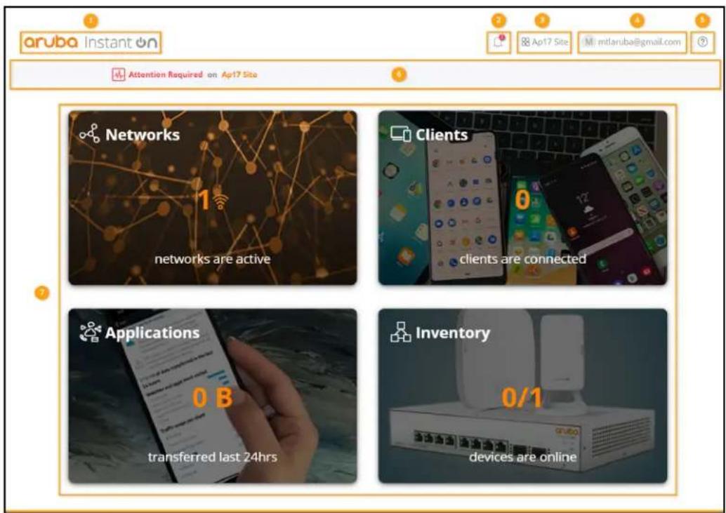
The Instant On user interface comprises the following components:
Table 8: Aruba Instant On User Interface Components
| Legend | Header Content | Description |
| 1 Aruba | Instant On logo | Displays the Aruba Instant On logo and functions as a button to return to Instant On home page. |
| 2 | Alerts ( ) | Displays the alerts that are triggered by the system when an unusual activity observed on the network. See Alerts for more information. |
| 3 | Site options(□) | Displays the site name and provides the following options to manage sites your administration:■ Site management—Allows you to modify various account settings, including |
Table 8: Aruba Instant On User Interface Components
| Legend | Header Content | Description |
| time zone and notifications for the selected site. For more information, se Management.Add new devices—Opens the Extend Network page and allows you to add a new device. For more information, see Extending your Network.Connect to another site—Allows you to connect to another Instant On site. After clicking Connect to another site, you are logged out of your current site and redirected to the Aruba Instant On login page. Enter the registered er ID and password to access the respective Aruba Instant On. If you have multiples sites configured under the same administrator account, you will be redirected to the My Sites page from where you can select one of the sites.Setup a new site—Allows you to setup a new Aruba Instant On site. For more information, see Setting Up Your Network. | ||
| 4 | Account options (@) | Displays the registered email ID and provides options to administer account information and setup notifications. The first letter of your e-mail id will be displayed in the circle. Account options allows you to perform the followingAccount management—Allows you to modify your account information for all associated sites. For more information, see Managing Your Account.Sign out—Allows you to log out of your Aruba Instant On account. |
| 5 | Help Ⓤ) | Provides the following options to reach Aruba Instant On support and addition details of the product:Help—Opens the Aruba Instant On documentation portal. For more information, seehttps://www.arubainstanton.com/techdocs/en/content/home.htm.Support—Listed below are the options available:Contact support- Opens the Aruba Instant On Support Portal, which provides information on warranty and support policy for the product you selected and also the on-call technical support. For more information, sehttps://www.arubainstanton.com/contact-support/.Support resources—Allows you to generate a support ID by clicking onGenerate Support ID button. The ID is then shared with Aruba Support personnel to run a diagnosis on your device.Community- Provide a place for members or participants to search for information, read and post about topics of interest, and learn from each For more information, see https://community.arubainstanton.com/.Technology partners & promotions- Provides details on the product, how it works, link to the support, and community page. For more information sehttps://www.arubainstanton.com/.About- Provides information about the software currently installed on the web application, and also the following information:End User License AgreementData Privacy Policy and Security Agreement |
Table 8: Aruba Instant On User Interface Components
| Legend | Header Content | Description |
| 6 Site health monitor | Provides the health status of devices connected to the network. Clicking on health monitor will take you theSite Healthpage. SeeMonitoring Site Healthfor more information on theSite Healthmodule. | |
| 7 Modules | Modules allow you to configure and monitor network components such as application usage and system alerts. Clicking on a module tile allows you to configure settings relevant to the module. The Instant On user interface cons the following modules:Networks: Provides a summary of the networks that are available for primary and guest users. SeeConfiguring Networksfor more information on theNetworksmodule.Clients: Provides connection information for the clients in your network.SeeManaging Clientsfor more information on theClientsmodule.Applications: Provides daily usage data for the different types of applications and websites accessed by clients in thenetwork. SeeAnalyzing Application Usagefor more information on theApplicationsmodule.Inventory: Specifies the number of devices on the site that are UP. 1 page also allows you to add a new device or remove an existing device Viewing and Updating Inventoryfor more information on the devices on t site. | |
Using the Instant On User Interface
Network operations of the Instant On network are managed through the site health monitor and other features present on the homepage.
Opening a Module
To open a module, click on the module tile on the home page. The settings relevant to the module will be displayed. When a particular module is open, the module tiles are arranged at the bottom of the page. You can switch between modules by clicking on the tiles below.
Closing a Module
To close a module and return to the Instant On home page in the web application, do one of the following:
- Click X at the top-right corner of the module.
- Click the Aruba Instant On logo at the top-left corner of the page.
Site Management
Click on the site name and select Site management from the drop-down menu. The Site Management page displays the following user settings that can be modified in the Aruba Instant On application:
■ Administration ■ Time zone ■ Guest portal ■ Software update
Administration
The Administration page allows you to modify administrator information, including your Aruba Instant On site name and account credentials. You can also add a secondary administrator account. See Administration Settings for more details on the Administration page.
Time Zone
The Time Zone page allows you to set the local time zone, date, and time for your Aruba Instant On site. See Time Zone Settings for more details on the Time Zone page.
Guest Portal
The Guest Portal page on the Instant On web application provides you with a Captive Portal and customize a welcome page as you see fit. The page also provides you with the option for Facebook Wi-Fi service to connect to the Internet. This is used in Guest networks without the secured password for authentication. See Configuring Guest Portal for more information.
Software Update
You can now manage your software updates by creating schedules using the Instant On web application. For more information, see Updating the Software Image on an Instant On Site.
Administration Settings
The Administration page allows you to modify administrator information, including your Aruba Instant On site name and account credentials. You can also add a secondary administrator account. Both accounts will have full privileges to the Instant On site configuration and status.
Modifying the Aruba Instant On Site Name
To modify the Aruba Instant On site name, follow these steps:
- Click on the site name and select Site management from the drop-down menu. The Administration page is displayed by default.
- Enter a new name for the Aruba Instant On site under Site name.

The site name must be between 1 and 20 alphanumeric characters in length.
Adding Secondary Accounts
Each Aruba Instant On site can be managed by three different administrator accounts. To add administrator accounts to your site, follow these steps:
- Click on the site name and select Site management from the drop-down menu. The Administration page is displayed by default.
- To add a secondary administrator account, click ( ) next to Account managing this site.
- Enter a valid email ID in the Email field and click Assign account to save the changes.
Changing your Secondary Account
To change your secondary administrator account, follow these steps:
- Click on the site name and select Site management from the drop-down menu. The Administration page is displayed by default.
- Under Second account, click Change second account. The Email field becomes editable.
- Enter a new email ID for the secondary account.
Transferring Account Ownership
Aruba Instant On allows you to transfer ownership from one administrator account to another. To transfer ownership of an Aruba Instant On site to another administrator account, follow these steps:
- Click on the site name and select Site management from the drop-down menu. The Administration page is displayed by default.
- Under Account(s) managing this site, click Transfer ownership. The Transfer Ownership page is displayed.
- Enter the new email ID under Email.
- Click Transfer ownership to transfer ownership of the site to the new administrator account.
After your account is removed, you are logged out of the site. A confirmation message is that ownership has been transferred successfully.
Time Zone Settings
The time zone is set automatically when the device is configured for the first time. However, change the time zone settings, the Time Zone page allows you to set the local time zone, date, and time for your Aruba Instant On site. This information is used for the following Aruba Instant On feature
■ Displaying daily statistics for your network.
■ Enforcing network availability schedules.
■ Performing daily image checks on the Aruba Instant On image server.
Setting a Local Time Zone
To set the local time zone for your Aruba Instant On site, follow these steps:
- Click on the site name and select Site management from the drop-down menu. The Administration page is displayed by default.
- Click Time zone to open the Time Zone page.
- Select a time zone from the Site local time zone drop-down list.
After the local time zone is set, Aruba Instant On automatically updates the local date and time under Site local date & time.
About Software
The About page provides information about the software currently installed on the web application. To view the following information in the About page, click the help ( ? ) icon from the page header and select About from the drop-down menu:
■ End User License Agreement ■ Data Privacy Policy and Security Agreement
Click OK to exit from the About page.
The Site Health page provides a summary of the health status of the Instant On devices connected to the network. It shows a consolidated list of alerts that are triggered from the devices provisioned. It also displays the inventory details of the connected devices and real-time data of active connections on an hourly basis with the cumulative transfer speed of all the devices.
One of the following messages is displayed at the bottom of the Site Health icon:
Table 9: Site Health Messages
| Message Description | ||
 | Everything is OK | This information alert indicates that there are no issues with the The color code is green. |
 | Potential Issue | This minor alert indicates one or several potential issues detected system. The color code is yellow. |
 | Attention Required | This major alert indicates one or several issues detected in the require immediate attention. These alerts have the highest severity color code is red. |
The alerts are classified based on the severity. The Alerts page in the Instant On web application prioritizes the alert that requires immediate attention by placing it at the top of the list. The Instant On when an unusual activity occurs on the site and requires timely action to be taken by the alerts are classified as follows:
■ Major active alert ( ) — The alerts classified as major are considered as the most severe and prompt the user to take an immediate action. These alerts are triggered when there is downtime of a device, synchronization failure, or when the Internet connectivity is down. - Minor active alert ( ) — The alerts are classified as minor when a degradation in performance is observed, but without any downtime. These alerts are triggered when a system or device has a device MAC address that is unauthorized.
Registered devices send or receive notifications when an alert is triggered by the Instant On unusual activity on the site. For information on how to enable or disable notifications for all Notifications.
The Site Health page also displays the Current transfer speed in bytes per second.
Click Show all alerts to view the list of alerts received on the site.
Click Show inventory to view a list of all the devices in the network, along with their operational status.
Alerts
Alerts are triggered by the system when unusual activity is observed with the network. To view the Alerts page, click the Alert (🔊) icon that appears on the title bar of the web application when there is a pending alert. The number of alerts in the system is displayed as a colored badge on the Alert (🔊) icon. The color of the badge determines the severity of the alert present in the system. When there are no alerts present in the system or all the alerts have been acknowledged, the Alert (🔊) icon will not appear in any of the title bars on the app or the application.
Viewing Alert History
To view the Alert history, follow these steps:
- Click the Site Health banner ( ) on the Instant On home page.
- On the Site Health main page, you will see the details of the latest alert. Click Show all alerts. The Alerts page displays a list of all the alerts received by the app, including the active alerts and the ones that have been cleared.
- Click the arrow ( ) next to the alert. The details of the alert are displayed.
When there are multiple active alerts received by the application, the summary box in the Site Health page displays the active alerts with the highest severity in the system along with their color codes. For example, Major active alert takes the highest priority and is displayed in a red summary box. The Alerts page displays the list of active alerts in descending order of their severity and the order by which they should be acknowledged.

The Inventory displays a list of devices in the network along with the devices' current operational status. To view the Inventory page, follow these steps:
- Click the Inventory (✗) tile on the Instant On web application home page or click the Site Health banner and then click on Show inventory.
- The Inventory page lists the APs and switches added in the network and their operational status. Click an AP or switch to view the details of the device.
The following table lists icons and their corresponding status:
Table 10: Device Status
| Status Icon | Condition | |
| Up Device is |  | reachable. |
| Down Device | is  | reachable. |
| Warning Reach |  | device with a major alert reported by the device. |
| Minor warning |  | Reachable device with a minor aleported by the device. |
Adding a Device
To add a device to the inventory list, follow these steps:
- Click the Inventory (☐) tile on the Instant On web application home page or click the Site Health banner and then click on Show inventory. The Inventory page is displayed.
- Click + Add devices.
- Place your Instant On device in its destination area and make sure it is powered on and connected to the Internet. Now select Search for my device. It usually takes around 4-5 minutes for the Instant On devices to be detected. Alternatively, you can choose to extend your network by clicking on How to extend my network. For more information, see Extending your Network.
- Review the device(s) discovered and add them to your site.
- If you still cannot find your device, click the I don't see my device button to view the troubleshooting options.
Types of Devices
Instant On supports three types of devices:
■ Access Points ■ Routers ■ Switches
Extending your Network
The How to Extend your Network page provides instructions on two different ways by which you can add more devices to your network.
■ Extend using a cable ■ Extend over-the-air (Mesh)
Extend using a Cable
This option is available to you on the UI only if you have chosen to configure the Instant network mode. To extend your network using a cable, follow these steps in the web application:
- In the How to Extend your Network page, choose Extend using a cable.
- To ensure optimal performance, connect your additional Instant On devices to the same first AP, using network cables. Power on the AP using Power over Ethernet (PoE) or DC (if you have ordered for it with the installation kit).
- Wait for the LED lights on the additional Instant On AP(s) to blink alternately between amber.
- Select Search for my device to make the Aruba Instant On scan for both wired and wireless devices. The AP should show up in the list of devices detected in the network.
- Review the device(s) discovered and add them to your site.
- If you still cannot find your device, click I don't see my device to view the troubleshooting options.
Extend Over the Air
To extend your network over the air, follow these steps in the web application:
- In the How to Extend your Network page, choose Extend over-the-air.
- Connect at least one Instant On AP to a local wired switch or a router and ensure it is complete.
- Place a wireless Instant On AP in a location within the Wi-Fi range and power it on. For more information, see Instant On AP Wireless Access Point Placement Guidelines.
- Wait for the LED lights on the wireless Instant On AP(s) to blink alternately between amber.
- Select Search for my device to make the Aruba Instant On scan for both wired and wireless devices. The AP should show up in the list of devices detected in the network.
- Review the device(s) discovered and add them to your site.
- If you still cannot find your device, click I don't see my device to view the troubleshooting options.
Instant On AP Wireless Access Point Placement Guidelines
Consider the following guidelines when installing additional APs in the wireless network:
- Interfering sources or obstacles—Check for interfering sources or obstacles and install the APs on a ceiling or a wall.
- Line of sight—If you can clearly see the wired AP from where you stand, it is likely that the AP will offer a strong signal and good coverage.
- No line of sight—When line of sight is not possible, the APs should be placed in a close range to each other. The number of obstacles and type of materials heavily influence and attenuate the scenario, a minimum distance of 16 feet (5 meters) and a maximum distance of 60 feet recommended between the APs. ■ Wireless APs are placed on different floors—If you place the APs on different floors, try to align them along a vertical line.
These are general guidelines and you may need to experiment with the placement of your Instant On settling down on a permanent location.
Deployment Scenarios for Outdoor Access Points
The versions prior to 1.4.0 of the Instant On product line includes both indoor and outdoor, the user interface did not allow specifying whether an AP is configured for servicing indoor environments. In the case of an outdoor AP such as AP17 being setup as a mesh point, i service disruptions when all the surrounding APs are indoor units. This is because many reg reduce the available channels for outdoor use. The result is that the indoor AP may choose that is unavailable to the outdoor AP and hence, the AP17 mesh point will never be able mesh portal. The following deployment scenarios for Outdoor APs help mitigate these problems:
Scenario 1: Provision a Site on the Outdoor AP Channel
In this solution, when the user attempts to extend the network, the UI prompts the user t the new AP is an outdoor AP (example: AP17) being added as a mesh point. If so, the e to operate on the outdoor AP channel as long as the outdoor AP is part of the Inventory outdoor AP is removed from the Inventory, and there are no other outdoor APs present, th switched back to operate on the AP installation default channel.
Scenario 2: New Site or Existing Site with no Outdoor Mesh Points
When extending the network, a choice is presented to the user to include the discovery of in the search. One of the following two outcomes are possible in this scenario:
If the user chooses to discover outdoor APs as part of the search by selecting the Include over-the-air outdoor devices in search checkbox:
- A warning message is displayed to indicate that the Wi-Fi network will be temporarily unavailable when search for over-the-air outdoor devices. All APs in the site are forced to the outdoor channel plan. All APs discovered in the search regardless of their type or connectivity status will be can be added to the inventory. If there are no outdoor APs discovered in this process, it is the default channel plan.
If the user chooses not to include Outdoor APs as part of the discovery operation:
The Search for my device operation will keep the default channel plan and search for both wired and wireless APs in the area. The over-the-air outdoor APs will be ignored in the search result. Outdoor APs can still be found and added to the inventory, but they will operate on a separate outdoor channel plan.
Scenario 3: Existing sites with Mesh outdoor Access Points

If a mesh outdoor AP cannot find a mesh portal on an outdoor channel, then it will be the user interface.
If a mesh outdoor AP is on a compatible channel, then the user interface displays it as u
Scenario 4: Deleting Last Outdoor Mesh Point
When deleting the last outdoor mesh point, the site will revert to its default channel plan.
Radio Management
The Radio Management page allows you to configure the radio channel on which the AP needs to operate.
This reduces interference and helps to optimize the AP radio performance as they will operate on selected channels and bandwidth. The radio management configuration is global to a site and can be accessed from the advanced menu in the Inventory page. The APs in the site will use only the selected channels and allowed channels for the channel width.
Follow these steps to configure a radio channel on which the AP should operate:
- Click the Inventory tile on the Aruba Instant On Portal home page or click the Site Health banner and then click on Show inventory.
- Click the advanced settings ( ) icon and select Radio management.
- Choose a Channel width for 2.4 GHz and 5 GHz Radios.
- Based on your selection, the Channel selection options will be refreshed. Select the required channels. The changes are saved automatically.
Access Point Lights
The Access Point Lights page allows you to turn on or off the device status and radio lights. The lights are turned on by default to provide a clear visual indicator of the device's status at a glance.
Follow these steps to turn on or off the access point lights:
- Click the Inventory tile on the Aruba Instant On Portal home page or click the Site Health banner and then click on Show inventory.
- Click the advanced settings (💡) icon. The Access Point Lights page is displayed.
- Choose one of the following options:
a. Normal mode (default)—Use this option to turn on the status and radio lights. This option is selected by default.
b. Quiet light mode—Use this option to turn off the status and radio lights. When this option is selected, the device lights are turned off during normal operation.
Loop Protection
The Loop Protection page is available only when there are one or more switches in the inventory. Instant On devices use two mechanisms for loop protection:
■ Aruba Proprietary Mechanism ■ Rapid Spanning Tree Protocol (RSTP)
Aruba Proprietary Mechanism
This mechanism is in-built on AP11D access points and Instant On switches to protect them from storms. This mechanism cannot be disabled on the device using the Instant On web application. It sends out a proprietary packet and blocks any port that receives the same packet. The device unblocks the port after 60 seconds once the fault is removed.
Rapid Spanning Tree Protocol (RSTP)
This mechanism is available only on the Instant On switches and is compliant with the 802.1D standard. RSTP provides loop protection in an interoperable environment with third-party networking equipment. The RSTP mechanism can be enabled or disabled on the network using the Instant On web application. When this mechanism is enabled, probe packets are sent out every 2 seconds from the root bridge. If the same packet is seen in more than one port of a downstream device, it indicates that a loop exists, and RSTP will block ports to create a loop-free topology.
Follow these steps to enable RSTP on the network:
- Click the Inventory tile on the Aruba Instant On home page or click the Site Health banner and then click on Show inventory.
- Click the advanced settings ( ) icon and select Loop protection.
- Slide the Rapid spanning tree (RSTP) toggle switch to enabled (☐), to configure loop protection on the network. The page lists the spanning tree diagnostics such as the Root switch connected to the network and its priority value. It also indicates the duration and number of times the Topology changed for the root switch device on the network.
Power Schedule
The Power Schedule page allows you to configure a schedule for Instant On switches and PoE capable devices to supply power to devices connected to them. This setting is global and applies to capable access points.
The Power Schedule feature does not take effect on:
■ Uplink port ■ Ports to which Instant On access points and switches are connected. ■ Link aggregation ports
Follow these steps to configure a power schedule for PoE powered devices on the network:
- Click the Inventory tile on the Aruba Instant On home page or click the Site Health banner and then click on Show inventory.
- Click the advanced settings ( ) icon and select Power Schedule.
- Select the days on which the switch should supply power to devices under Days of the week.
- Configure the time period for when the devices should be powered through PoE under Active hours during the day.
a. All Day - The switch provides power to the connected PoE devices throughout the day. b. Active Between - The switch provides power to the connected PoE devices for the specified time period. Configure the Start Time and End Time for PoE supply as required.
Although the Power Schedule option is globally applicable, the usage of the schedule can be individual ports. The option to turn off power schedule for individual ports is available in the Port section of the Switch Details page. For more information, see Power Management.
DNS
The DNS page allows you to configure the DNS server used by the Instant On network. This is for the Instant On network.
Follow these steps to configure a DNS server for the network:
- Click the Inventory tile on the Aruba Instant On home page or click the Site Health banner and then click on Show inventory.
- Click the advanced settings ( ) icon and select DNS.
- Select either of the three options:
■ Automatic (default) — Configure Cloudflare DNS (1.1.1.1) as the DNS server. This option is selected by default.
■ Network assigned — Configure DNS assigned by the network as the DNS server, for networks without a router.
■ ISP assigned — Configure DNS assigned by ISP as the DNS server, for networks with a router.
■ Custom — Specify a custom DNS server. You can create up to 3 DNS servers for the network. To create a custom DNS server, follow these steps:
a. Select the Custom radio button.
b. Enter the IP address of the DNS server and click +. To remove a DNS server, click on the delete icon next to the DNS entry.
The Access Point Details page provides details of the selected AP, which includes the AP name, IP address,
MAC address, serial number, radio, ports, and model type of the AP. This page also provides the wireless radios including the number of clients that are currently connected. To view the Details page, follow these steps:
- Click the Inventory (☐) tile on the Aruba Instant On home page or click the Site Health (☐) banner and then click on Show inventory.
- Click the (>) arrow next to an AP in the Inventory list. The AP details such as the AP name, IP address of the AP, MAC address, Serial number, AP type, radio, and the number of the clients each radio channel are displayed.
The following options are available in the Access Points Details page:
■ Identification
■ Connectivity
Ports Actions
Identification
Radios
This section provides details on the clients operating on the 2.4 GHz and 5 GHz radios of
■ Number of clients connected—Denotes the number of clients connected to the radio. ■ Operation channel—Denotes the radio channel on which the connected clients are operating. ■ Radio transmit power—Denotes the radio transmit power rate (in dBm) for the connected clients. ■ Airtime utilization—Denotes the airtime utilization (in %) detected by the radio.
Connectivity
You can either configure Instant On devices to automatically receive an IP address from a DHCP server running on the LAN, or manually configure a static IP address. To configure IP assignment for an access point, follow these steps:
- Click the Inventory (☐) tile on the Aruba Instant On home page, or click the Site Health (☐) banner and then click Show inventory. The Inventory page is displayed.
- Click the arrow next to an AP in the Inventory list, and then click the Connectivity tab.
- Select one of the following options to assign an IP address to the AP:
■ Automatic (default) — The IP address for the AP is assigned by the DHCP server. ■ Static — Assign a static IP address to the AP and configure the following parameters:
a. LAN IP — Enter a static IP address. b. Subnet mask — Enter the subnet mask. c. Default gateway — Enter the IP address of the default gateway. d. DNS server — Enter the IP address of the DNS server.
- Click Save.
Ports
Every network requires the E0/PT or ENET port of the AP to be connected to the gateway Ethernet cable. The Port Details page displays the ENET port, the uplink status, and the upload throughput rates. The name of the Ethernet port can be changed by entering a new name in the Port ENET text field.

The Port details link will not be displayed if the AP is connected as a mesh point in the network.
Connected Clients and Devices
When you select the ENET port, the Clients and devices connected to this port section displays the list of clients and devices connected to the port. By default, the clients and devices for All Networks applicable to the port are displayed. The clients and infrastructure devices directly connected to the port have a link to the client details page. The indirectly connected clients are displayed by their MAC address. To view clients and devices connected to a specific network, select a network from the Show drop-down list.
Actions
The Actions tab provides the following configuration options.
Locate
Instant On allows you to locate your device when there are many devices in the site.
To locate your device, follow these steps:
- Click the Inventory (✗) tile on the Instant On web application home page or click the Site Health banner and then click on Show inventory. The Inventory page is displayed.
- Click the (>) arrow next to an AP in the Inventory list and then click on Actions tab.
- Slide the Activate lights toggle switch to right ( ) to turn on the locator light in the device. The locator light will be active for 30 minutes after you turn on the toggle switch. The light default.
Restart
Aruba allows you to restart the device if you suspect any problem with it.
To restart your device, follow these steps:
- Click the Inventory(☐) tile on the Aruba Instant On home page or click the Site Health(☐) banner and then click on Show inventory.
- Click the ( ) arrow next to an AP in the Inventory list and then click Actions tab.
- Click Restart.
Remove from Inventory
Follow these steps to remove an AP which is still online:
- Click the Inventory(☐) tile on the Aruba Instant On home page or click the Site Health(☐) banner and then click on Show inventory.
- Select the AP you want to remove from the inventory by clicking the ( ) arrow next name.
- In the Actions tab, click Remove next to Remove from inventory.
- Click Remove in the popup window that appears on the screen.
Follow these steps to remove an AP which is offline:
- Navigate to Inventory. Select the AP you want to remove from the inventory by clicking the (>) arrow next to the AP name. In the Actions tab, a rectangular bar appears below the device name when an alert is triggered. The color of the rectangular alert bar will appear according to th
- Click the Alerts link. You will be directed to the Alert Details page which provides more information about the unusual activity. The Advanced menu does not appear on the title bar when the status is down.
- If the Instant On device is removed from the network, you can choose to remove the inventory by clicking Remove from inventory in the Actions tab. A pop-up box appears on the screen requesting your confirmation.
- Click Remove to delete the device from the inventory.
Router Details
The Router Details page provides details of the selected Wi-Fi router, which includes the Router address, MAC address, serial number, radio, ports, and model type. This page also provides a wireless radios including the number of clients that are currently connected. Instant On current AP11D devices to operate as a primary Wi-Fi router in the network. To view the Router De these steps:
- Click the Inventory(☐) tile on the Aruba Instant On home page or click the Site Health(☐) banner and then click on Show inventory.
- Click the ( ) arrow next to an AP11D router in the Inventory list.
Identification
The Identification section displays details such as the Router name, IP address, MAC address, Router type, radio, and the number of the clients connected on each radio channel.
Radios
This section provides details on the clients operating on the 2.4 GHz and 5 GHz radios of
■ Number of clients connected—Denotes the number of clients connected to the radio. ■ Operation channel—Denotes the radio channel on which the connected clients are operating. ■ Radio transmit power—Denotes the radio transmit power rate (in dBm) for the connected clients. ■ Airtime utilization—Denotes the airtime utilization (in %) detected by the radio.
Connectivity
The Instant On AP11D device is connected as a primary Wi-Fi router to the ISP provided in Ethernet cable. The Connectivity section lists the gateway IP address of the uplink and the Internet IP
forwarded by the ISP provided modem to the router. The Instant On router acts as a DHCP local network and provides IP addresses to requesting devices. To configure LAN IP assignment AP11D router, use the following procedure:
- Base IP address — Configure the LAN IP address for the router interface.
- Subnet mask — Configure the subnet mask for the network.
- Click Save.
Ports
Every network requires the E0/PT or ENET port of the AP or Router to be connected to the using an Ethernet cable. Each Instant On AP has a single port, except for the AP11D device additional 3 LAN ports—E1, E2, and E3 respectively. These ports can be used to connect additional network. The ports are visually represented on the page in the same manner as the actual device. The E0/PT or ENET port is always selected by default and acts as the default router. To view the details of the ports and the uplink status, follow these steps:
- Click the ( ) arrow next to an AP11D router in the Inventory list.
- Under the Ports tab, select any of the ports to view the following details:
■ Port number — The physical port number of the router. ■ Port status — The speed of the trunk is displayed if the port is the member of a trur
■ Upstream and Downstream throughput — The upstream and downstream throughput of the trunk is displayed when the port is the member of a trunk.
Instant On currently supports an AP11D device to operate as a router in the network. The Ports section for unconnected ports consists of the following settings:
■ Active — Select the checkbox to enable the port. To disable the port, unselect the checkbox. ■ Name of the port in read and write mode.
Authentication and Security
■ Port access control (802.1X) — Select the checkbox to enable port-based network access control designed to enhance 802.11 WLAN security. Configure the following RADIUS settings when this is enabled:
Primary RADIUS Server — Configure the following parameters for the Primary RADIUS Server. If you are using the Instant On mobile app, tap More RADIUS parameters to view the below settings. - RADIUS Server IP address — Enter the IP address of the RADIUS server. - Shared secret — Enter a shared key for communicating with the external RADIUS server. - Server timeout — Specify a timeout value in seconds. The value determines the timeout for a RADIUS request. The Instant On device attempts to send the request several times (as configured in the Retry count) before the user gets disconnected. For example, if the Timeout is 5 seconds, Retry counter is 3, user is disconnected after 20 seconds. The default value is 5 seconds. - Retry count — Specify a number between 1 and 5. Retry count indicates the maximum number of authentication requests that are sent to the server group, and the default value is 3. - Authentication port — Enter the authentication port number of the external RADIUS server in the range of 1-65535. The default port number is 1812.
- Send RADIUS Accounting — Select the checkbox to send RADIUS accounting messages. ■ Secondary RADIUS Server — Select the checkbox to configure a secondary RADIUS server and configure the following parameters:
- Server IP address — Enter the IP address of the secondary RADIUS server.
- Shared secret — Enter a shared key for communicating with the external RADIUS server.
- Authentication port — Enter the authentication port number of the external RADIUS server in the range of 1-65535. The default port number is 1812.
Included networks
■ This section includes the following configuration settings:
All networks (default) — The user can assign network traffic based on the VLAN tag or default network. By default, all ports assigned traffic from all networks are based on the default network. - Specific networks only — On selecting this option, the port's traffic will only be allowed from the specified network.
Clients and devices connected to this port
On selecting a specific port of an AP11D router, the Clients and devices connected to this port section displays the list of clients and devices connected to the port. By default, the clients and devices for All
Networks applicable to the port are displayed. The clients and infrastructure devices directly connected to the port are displayed as a link to the client details page. The indirectly connected clients
their MAC address. To filter the clients and devices connected to a specific network, select a Show drop-down list.
Networks
After creating your network, you have the option to map the network to a VLAN port, which can carry traffic from all networks or only from a specific network. Each port on the Instant On AP11D is assigned a separate VLAN ID and configured to manage network traffic. The following process describes how to map a network to a VLAN port:
- Click the Inventory (☐) tile on the Instant On web application home page, or click the Site Health banner and then click on Show inventory. The Inventory page is displayed.
- Click the (>) arrow next to an AP11D router in the Inventory list and then click on the Networks tab.
- From the Selected network drop-down list, choose the network you want to map to a specific port.
- Click the port to which you want to assign the selected network.
- Click the Ports tab to view the configuration details of the port mapped to the selected network.
- Click Save to finish mapping the network to the port.
Actions
The Actions tab provides the following configuration options.
Locate
Instant On allows you to locate your device when there are many devices in the site. To locate your device, follow these steps:
- Click the Inventory (✗) tile on the Instant On web application home page, or click the Site Health banner and then click on Show inventory. The Inventory page is displayed.
- Click the (>) arrow next to an AP11D router in the Inventory list and then click on the Actions tab.
- Slide the Activate lights toggle switch to the right ( ) to turn on the locator light in the device. The locator light will be active for 30 minutes after you turn on the toggle switch. The light is on by default.
Restart
Aruba allows you to restart the device if you suspect any problem with it. To restart your device, follow these steps:
- Click the Inventory (☐) tile on the Aruba Instant On home page or click the Site Health (☐) banner and then click on Show inventory.
- Click the (>) arrow next to an AP11D router in the Inventory list and then click Actions tab.
- Click Restart.
Replacing a Router from the Inventory
Instant On allows you to replace a router from the inventory when it goes offline. A new or existing router from the site can be used to replace your old router. The old router needs to be manually reset to use as a normal router. This option is available only if the device selected from the inventory list is offline. To replace the router from the inventory, follow these steps:
- Click the Inventory ( ) tile on the Aruba Instant On home page or click the Site Health ( ) banner and then click on Show inventory. The Inventory page is displayed.
- Click the (>) arrow next to the router you want to replace from the Inventory list. A rectangular bar appears below the device name when an alert is triggered.
- Click the Alerts link. You will be directed to the Alert Details page which provides more information about the unusual activity and a link to replace the router.
- In the Alert Details page, click on the replace link. The Replace router page is displayed. Alternatively, you can perform this action by clicking the Replace hardware button in the Actions tab.
- Unplug the router that you want to replace and plug in your new Instant On device modem. When your device's lights are alternating between green and amber, click Continue.
- Enter the serial number located on your new Instant On primary Wi-Fi router and click Search.
- Once your preferred router is detected, select Replace to configure the device as your primary Wi-Fi router.
- Click Finish when your new router is added to your network.
Switch Details
To view the Switch Details page, follow these steps:
- Click the Inventory(☐) tile on the Aruba Instant On home page or click the Site Health(☐) banner and then click on Show inventory.
- Click the (>) arrow next to a switch in the Inventory list. The Device details page of the switch is displayed.
The Device details page of the switch contains the following sections:
■ Identification
Connectivity
Ports
Link Aggregation
Actions
Identification
Displays the device information such as device name, PoE power usage, uplink connectivity, and address.
Device name
The device name is displayed in read/write mode. You can change the name of the device, maximum number of characters supported is 32.
Connectivity
Displays the details of uplink connection. When the switch is connected to a network device port, a link to the device details page of the device is displayed.
Local network IP
Displays the local network IP of the switch.
Power over Ethernet (PoE)
The Power over Ethernet section provides the following information:
Total budget—The total power in watts that can be provided by the switch. Power consumption—The amount of power in watts currently being consumed by the connected PoE devices.
Connectivity
LAN IP
Configure the IP assignment for the Instant On switch. You can configure either one of the
The Instant On switch will reboot to apply the configuration changes.
■ Automatic (Default) — The Instant On switch will inherit the IP address assigned by the DHCP in the network. ■ Static — Specify a static IP address for the Instant On switch by entering the following network parameters:
- LAN IP — Enter the IP address for the switch.
- Subnet mask — Enter the subnet mask. Default gateway — Enter the IP address of the default gateway. DNS server — Enter the IP address of the DNS server.
Routing
Configure routing on the Instant On switch. Routing is disabled by default. To configure routing, perform the following steps:
- To enable routing on a switch, select the Allow routing between networks checkbox. To disable routing, deselect the checkbox.
- When Allow routing between networks is selected, an icon is displayed next to networks that can be routed. If the icon is not visible, it implies that routing is turned off for the network.
- To configure routing for a network, select the network to view the routing options:
a. Select the Allow routing checkbox to turn on routing. To turn off routing, deselect the checkbox.
b. Configure either of the following options to assign an IP for the network:
■ Automatic (default) — The network will receive IP address from a DHCP server. ■ Static — Define the IP address assignment for the network by entering the following network parameters:
- Network IP address — Enter the IP address for the network.
- Subnet mask — Enter the subnet mask for the network.
- Click on Save to apply configuration changes. The routing configuration is applied after the Instant On switch reboots.


A minimum of two wired networks must be configured in the site to perform routing.
The Instant On switch must be online to configure routing.
Routing can be performed by only one Instant On switch in a site.
Ports
The ports are visually represented on the page in the same manner as the actual physical. Each port is numbered according to the port number on the switch and displays its current always selected by default and acts as the default uplink port for the switch. Select a port configuration. When a port is selected the following options are displayed:
■ Name of the port in read and write mode ■ Active — Select the checkbox to enable the port. To disable the port, unselect the checkbox.
Authentication and Security
■ Port access control (802.1X)—Select the checkbox to enable 802.1X authentication before a device can connect to a port. Configure the following RADIUS settings when this option is enabled:
- Send RADIUS Accounting— Select this checkbox to send RADIUS accounting messages.
Primary RADIUS Server—Configure the following parameters for the Primary RADIUS Server:
- Server IP address—Enter the IP address of the RADIUS server.
- Shared secret—Enter a shared key for communicating with the external RADIUS server.
- Server timeout—Specify a timeout value in seconds. The value determines the timeout for a RADIUS request. The Instant On device attempts to send the request several times (as configured in the Retry count) before the user gets disconnected. For example, if the Timeout is 5 seconds, Retry counter is 3, user is d seconds. The default value is 5 seconds.
- Retry count—Specify a number between 1 and 5. Retry count indicates the maximum number of authentication requests that are sent to the server group, and the default value is 3 requests.
- Authentication port—Enter the authentication port number of the external RADIUS server within the range of 1-65535. The default port number is 1812.
- Secondary RADIUS Server—Select this checkbox to configure a secondary RADIUS server. When selected, configure the following parameters:
- Server IP address—Enter the IP address of the secondary RADIUS server.
- Shared secret—Enter a shared key for communicating with the secondary RADIUS server.
Authentication port—Enter the authentication port number of the secondary RADIUS server within the range of 1-65535. The default port number is 1812.
■ Security protections—Enable this setting when untrusted devices are connected to the port. This setting in combination with Network Security configuration is used to prevent DHCP and ARP the wired network. For more information, see Network Security.
Included networks
- All networks (default)—The user can assign network traffic based on the VLAN tag or through the default network. By default, all ports assigned traffic from all networks are based on the
- Tagged— Select the checkbox to tag traffic from the port with a VLAN tag. On enabling this option, the port will receive and send traffic from the default network using the VLAN tag.
- Specific network only—On selecting this option, the port will only allow traffic from the specified network and all other traffic will be excluded from the port. On selecting this option, an Assigned network dropdown option is displayed. Select the network you want to assign to the port from the list of configured networks. Similar to the All networks (default) setting, selecting this option tags incoming and outgoing traffic from the port with the VLAN tag.
Clients and devices connected to this port
- Lock—Allows you to lock the port and stop new devices from joining the port. When a port is locked, all clients connected to the port are allow-listed and granted access to the port while new clients are blocked. The port must be unlocked to allow new devices to connect. This option is unavailable when Instant On devices are connected. This option is displayed when clients and devices are connected to the port.
To lock a port on an Instant On switch, select the Lock checkbox. Deselect the Lock checkbox to unlock the port.

The maximum number of ports that can be locked in an Instant On switch is 10. The maximum number of clients that can be locked per port is 10.
■ Show—Allows you to view devices connected to the port sorted by network. By default, All Networks is selected. To filter the clients and devices connected to a specific network, select a network from the drop-down list. The clients and infrastructure devices directly connected to the port are displayed, and clicking on a device takes you to the client details page. The indirectly connected clients are displayed by address.
Power Management
Power management options allow you to configure PoE supply to devices connected to the switch. These options are unavailable for ports that are part of LACP.
■ Power supply policy — Select either one of the following options to configure a power supply policy for the port:
Usage (default) — The power allocated to the port is based on usage and is unrestricted. Class — The power allocated to the port is based on the PoE standard of the device. The power class of devices are categorized as follows:
| Class | Power | Devices | ||
| Class 1 | 0.44 | -3.84 Watts | IP Phones | |
| Class 2 | 3.84 | -6.49 Watts | IP Cameras | |
| Class 3 | 6.49 | -12.95 Watts | Devices supporting | 802.3af PoE standard |
| Class 4 | 12.95 | -25.5 Watts | Devices supporting | 802.3at PoE standard |
- Port Priority — Assigns a priority level to the ports. When there is a budget constraint for delivering PoE power at the switch, power is delivered to the connected devices based on the port priority. Power is delivered in the following order: Critical > High > Low. Under Port Priority, assign any one of the following priority levels to the port:
Low (default) — Configures the port as a low priority port. - High — Configures the port as a high priority port. Critical — Configures the port as a critical priority port.

When two ports belonging to the same priority are demanding power, the port with the least port number is given priority. Example: When port 2 and 5 are assigned Critical class and the switch has a power budget constraint, the device on port 2 will receive full power and the remaining power budget will be allocated to the device on port 5.
- Use site power schedule — Select this checkbox to either enable or disable power schedule on the port. If enabled, the PoE supply to the port is determined by the power schedule defined. To schedule, click on Edit site power schedule. For more information on configuring Power Schedule, see Power Schedule.
Networks
After creating your network, you have the option to map the network to a VLAN port which traffic from all networks or only for a specific network. Each port in the Instant On switch separate VLAN ID and configured to manage the network traffic.
To assign network to a port, click on Selected network drop-down list and choose the network you want to map to the port.
Link Aggregation
Link aggregation configuration depends on the number of ports available on the switch. Instar supports switches with the following number of ports:
Table 11: Switch Ports Aggregation
| Number of Ports per Switch | Number of LAG Supported | Number of LAG members supported |
| 8 ports 4 trunks 4 trunk members | ||
| 24 ports 8 trunks 4 trunk members | ||
| 48 ports 16 trunks 8 trunk members |
The following procedure describes how to add a link aggregation group on the switch:
- Click the (>) arrow next to a switch in the Inventory list and select the Link Aggregation tab.
- Click the + Add link aggregation link. The following configuration options are displayed:
■ Active—Select this option to enable the LACP ports. It indicates that the port members of the link aggregation are available for devices to connect. Unselect the checkbox to disable the LACP
■ Name—Provide a custom name for the Link aggregation in the text field.
- Port members—Click on the respective ports you want to add as members for the link aggregation. The selected port members are displayed below separated by commas.
Delete—Click on delete to delete the Link Aggregation.
Aggregation mode
Select one of the following aggregation modes:
■ Static (default)—This option is selected by default. It indicates simple aggregation of ports with no active link detection or failover. ■ LACP—Selecting this option indicates dynamic detection and automatic failover when connected to other LACP (802.3ad) capable switches. This mode will allow only one user defined network through aggregated link. This option will pass the management VLAN network as untagged and all others as tagged.
Included networks
This section includes the following configuration settings:
- All networks (default)—The user can assign network traffic based on the VLAN tag or through the default network. By default, all ports assigned traffic from all networks are based on the
- Tagged—Select the checkbox to tag traffic from the network with a VLAN tag. On enabling this option, the network traffic is tagged with a VLAN tag.
- Specific network only—On selecting this option, the port will only allow traffic from the specified network and all other traffic will be excluded from the port. On selecting this option, an Assigned network dropdown option is displayed. Select the network you want to assign to the port from the list of configured networks. Similar to the All networks (default) option, selecting this checkbox will tag incoming and outgoing traffic from the port with the VLAN tag.
Clients and devices connected on this link aggregation
Show— Allows you to view devices connected to port sorted by network. By default, All Networks is selected.
To filter the clients and devices connected to a specific network, select a network from the list. The clients and infrastructure devices directly connected to the port are displayed as a link to the client details page. The indirectly connected clients are displayed by their MAC address.
Actions
The Actions tab displays the following options:
- Locate ■ Restart ■ Switch to Local Management ■ Remove from Inventory
Locate
Instant On allows you to locate your device when there are many devices in the site.
To locate your device, follow these steps:
- Click the Inventory (💡) tile on the Instant On web application home page or click the Site Health banner and then click on Show inventory. The Inventory page is displayed.
- Click the (>) arrow next to an AP in the Inventory list and then click on Actions tab.
- Slide the Activate lights toggle switch to right (☐) to turn on the locator light in the device. The locator light will be active for 30 minutes after you turn on the toggle switch. The light default.
Restart
To restart the device, follow these steps:
- Click the Inventory (☐) tile on the Aruba Instant On home page or click the Site Health (☐) banner and then click on Show inventory.
- Click the (>) arrow next to an AP in the Inventory list and then click Actions tab.
- Click Restart.
Switch to Local Management
The Switch to local management option allows you to change the switch management from cloud to local mode. When this option is selected, the switch will be removed from the site and the existing configuration will be stored on the switch. For more information, see Local Management for Switches.
Remove from Inventory
Follow these steps to remove a switch which is still online:
1. Click the Inventory (☐) tile on the Aruba Instant On home page or click the Site Health (☐) banner and then click on Show inventory.
- Select the switch you want to remove from the inventory by clicking the ( ) arrow next to the name.
- In the Actions tab, click Remove next to Remove from inventory.
- Click Remove from the popup window to remove the switch from the inventory.
Follow these steps to remove a switch which is offline:
- Click the Inventory (☐) tile on the Aruba Instant On home page or click the Site Health (☐) banner and then click on Show inventory.
- Select the switch you want to remove from the inventory by clicking the ( ) arrow next to the name.
- In the Actions tab, a rectangular bar appears below the device name when an alert is triggered. The color of the rectangular alert bar will appear according to the alert type.
- Click the Alerts link. You will be directed to the Alert Details page which provides more information about the unusual activity. The Advanced menu does not appear on the title bar when the status is down.
- If the Instant On device is removed from the network, you can choose to remove the inventory by clicking Remove next to Remove from inventory in the Actions tab. A pop-up box appears on the screen requesting your confirmation.
- Click Remove to delete the device from the inventory.
Topology
The Topology tab in the Inventory page displays an overview of the Instant On network. Information such as the network topology, state of network devices, number of connected clients, and status of link network devices are displayed in this page. Place the cursor over a device to view the device information card.
Click on a device to go the device settings page.
An example of the topology page is displayed below:
![graph TD A["..."] --> B["2"] B --> C["..."] B --> D["..."] B --> E["..."] C --> F["0"] D --> G["0"] E --> H["0"]](/content/2026/06/1350105/images/34a2fdb93368da010e4690f1cc7d1cd1c6720963604b9a9a64e079d8619bc31b.jpg)

Use the mouse scroll to zoom in and zoom out of the network topology.
Description of Topology Icons
| Icon Description | |
| Links | |
| — | Indicates an active wired connection. |
| ---- | Indicates an active wireless connection. |
| — | Indicates an inactive wired connection. |
| --- | Indicates an inactive wireless connection. |
| — | Indicates a restarting wired connection. |
| --- | Indicates a restarting wireless connection. |
| — | Indicates a wired connection that is being deleted. |
| --- | Indicates a wireless connection that is being deleted. |
| Devices | |
 | Indicates an AP11, AP12, AP15, or AP22 access point. |
 | Indicates an AP17 access point. |
 | Indicates an AP11D access point. |
 | Indicates an Instant On router. |
 | Indicates an Instant On switch. |
 | Indicates third party switches. This icon is displayed in the topology only devices are connected to the third party switch. |
| Connection Type | |
 | Indicates that the network is connected to a router. |
 | Indicates that the network is connected to a private network. |
| Connected Clients | |
 | Indicates the number of wired and wireless clients connected to the device |
Description of Device Information Card

- Device name
- IP address
- MAC address
- Serial Number
- Device Model (for Instant On devices only)
- Number of connected clients
- Status of device connectivity
NOTE: If the serial number of the device is the same as the device name, the serial number is not displayed in the device information card. The serial number of the AP is used as the device name by default.
NOTE: If the MAC address of the device is the same as the device name, the MAC address is not displayed in the device information card.
Auto-Detection and Auto-Configuring of Switch Ports
In a scenario where one Instant On device is connected to another, the Instant On system automatically configures ports to avoid the complexity of manually reconfiguring the port. The auto-configuration feature provides the following capabilities:
- When a second Instant On device is requesting power on a port, this port is set to Critical PoE priority to maintain the service as much as possible.
- All networks are made available on that port, in order to ensure that services from another Instant On device can operate freely. If the auto-configured port is connected to another Instant On device, the status of the port is set to Trusted. Users are not permitted to change the Ports settings that interfere with the auto-configuration service.
The Aruba Instant On web application provides a summary of the networks that are available and guest users.
To view the Networks page, click the Networks tile on the Aruba Instant On home page:

Figure 2 Screenshot of Network Dashboard
Table 12: Network Information
| Parameter Description | |
| Name Identifies the Instant | On network used to connect computers, tablets, or phones together. The network name is also used as the Wi-Fi identifier. |
| Type Indicates if the network is a employee guest network. | |
| Status Shows the status of the network. | |
| Wired Network / VLAN Wired Networks: Shows the VLAN ID that was assigned for the network.Wireless Network: Shows the network name of the network. | |
| Security | Shows the security option set for the network. |
| Clients | Shows the number of clients currently connected to the network. Click the number listed under Clients to view the details of the client selected. Se Managing Clients for more information about the Clients page. |
| Transferred | Shows the volume of data, in bytes, transferred in the network day. |
For more details about a specific network, select one of the following networks from the Networks page:
■ Employee Network ■ Guest Network ■ Wired Network
Employee Network
An Employee network is a classic Wi-Fi network. This network type is used by the employee organization and it supports passphrase-based (PSK) or 802.1X-based authentication methods. Employees may access the protected data through the employee network after successful authentication. This network is selected by default during a network profile configuration.

The very first employee network you create for the site cannot be deleted unless you choose to delete entirely from your account.
To configure an employee network:
- Click the Networks tile on the Instant On web application home page.
- Click Add+() and select Identification tab.
- Select the Wireless option in the Network Type selection. The wireless option appears only when your site has both wired and wireless networks.
- Select Employee, under Usage to indicate that the network is for an enterprise.
- Enter a Network name for the employee network. This will also be broadcasted as the SSID for the WLAN network.
- Configure any one of the following security options:
a. Password—Selecting this option displays the Network password (PSK) options. This enables you to secure the network using a shared password (PSK). Create a password of your Network password field. WPA2 Personal is enabled by default. To enable WPA2 + Personal, select the checkbox.
b. RADIUS—Selecting this option displays the Authentication server (RADIUS) options. This enables you to secure the network using a higher encryption RADIUS authentication. To configure a RADIUS server, update the following parameters:

You must configure the RADIUS server to allow APs individually or set a rule to allow the entire subnet.
■ WPA2 + WPA3 Enterprise—WPA2 Enterprise is enabled by default. To enable WPA2 + WPA3 Enterprise, select the checkbox.
Send RADIUS Accounting—Select this checkbox to send RADIUS accounting messages.
■ Primary RADIUS Server—Configure the following parameters for the Primary RADIUS Server.
- Server IP address—Enter the IP address of the RADIUS server.
- Shared secret—Enter a shared key for communicating with the external RADIUS server. Server timeout—Specify a timeout value in seconds. The value determines the time of RADIUS request. The Instant On AP attempts to send the request several times (as the Retry count) before the user gets disconnected. For example, if the Timeout is 5 and Retry counter is 3, user is disconnected after 20 seconds. The default value is 5.
- Retry count—Specify a number between 1 and 5. Retry count indicates the maximum number of authentication requests that are sent to the server group, and the default value is 3.
- Authentication port—Enter the authentication port number of the external RADIUS server within the range of 1–65535. The default port number is 1812. Secondary RADIUS Server—Select this checkbox to configure a secondary RADIUS server. When selected, configure the following parameters:
- Server IP address—Enter the IP address of the secondary RADIUS server.
- Shared secret—Enter a shared key for communicating with the secondary RADIUS server.
Authentication port—Enter the authentication port number of the secondary RADIUS server within the range of 1-65535. The default port number is 1812.
■ Network Access Attributes - Configure the following settings under Network Access
Attributes, if you wish to proxy all RADIUS requests from the Instant On AP to the
- NAS identifier—Enter a string value for RADIUS attribute 32, NAS Identifier, to be sent in RADIUS requests to the RADIUS server.
• NAS IP address—Select one of the following options if your Instant On devices are in a private network mode. The options below determine how the RADIUS authentication is performed across all networks. This option is grayed out if the Instant On AP is configured as the primary Wi-Fi router on the network. In that case, each AP in the network will send RADIUS requests to the server with a matching Source IP address and NAS IP address.
- Use device IP (default)—This is the default setting. The RADIUS requests and NAS IP will originate from each device authenticating the clients.
Use a single IP—The RADIUS and NAS IP address will originate from a single IP address representing the site. Enter the NAS IP address for the site.
7. Click Save.

After you configure an Employee network and save its settings for the first time, an Active checkbox appears in the Employee Details page indicating the network is currently Active. Use this checkbox to enable or disable the employee network.
Identification
To modify the network name or password of the employee network in the Aruba Instant On, follow these steps:
- Click Networks on the Instant On home screen. The Networks screen is displayed.
- Select the employee network from the Networks list to view the Employee Network Details screen.
- Click the Identification tab.
- Enter a new name under Network name to change the main network name or a new password under Network password to change the main network password. A warning message appears, indicating that changes to the network settings will disconnect all clients currently accessing the network.
- Click Save.
Options
The Options tab in the web application allows you to configure the bandwidth limit on internet usage along with IP and VLAN assignment for clients on employee or guest networks. To configure, select the employee network or guest network and then click the Options tab.
Show Network
The Show network checkbox is selected by default to broadcast the employee network or guest in the list of available Wi-Fi networks. Deselect the checkbox if you want to disable the selected network.
Wi-Fi 6
The Wi-Fi 6 checkbox configures the Wi-Fi 6 (802.11ax) capabilities of the network. When selected, 802.11ax capable clients can make use of enhanced throughput and transmission capabilities of the 802 standard. This setting is enabled by default.
The Wi-Fi 6 option is only available when the device inventory has at least one Aruba Instant On AP2 point.
Disable this feature if the client experiences problems connecting to the network.
Optimize for Video Streaming
This option enhances the quality and reliability of streaming videos by converting multicast streams to unicast streams over the wireless network, while also preserving the bandwidth available to the clients.
This option is disabled by default, as some wireless clients may not be compatible with this optimization.
To configure optimization for video streaming, follow these steps:
- Click the Networks (✗) tile on the Instant On home page. The Networks page is displayed.
- Click the ( ) arrow next to the employee or guest network to view the configuration, then click Options.
- Select the Optimize for video streaming checkbox.
- Click Save.
Limit Bandwidth Usage
The bandwidth consumption for an employee or guest network can be limited based on the MAC address. The configured limit will be maintained even when the client roams from one, within the network. As an alternative, you can choose to set the bandwidth on an entire n restricting the usage per client.
To configure a bandwidth limit for each client connected to the network, follow these steps:
- Click the Networks tile on the Instant On home page. The Networks page is displayed.
- Click the arrow next to the employee or guest network to view the configuration, then click Options.
- Select the Limit bandwidth usage checkbox.
- Under Restrict bandwidth usage by, select the Client radio button.
- Move the slider to set the bandwidth limit for the employee or guest network. The limit is set to 25 Mbps by default. The available speed limits are:
1 Mbps—Good for emails, VoIP, web surfing, music, and social media. 5 Mbps—Good for online gaming, video conferences, and streaming videos. 10 Mbps—Good for HD video streaming. 25 Mbps—Good for 4K video streaming.
- Click Save.
To configure a bandwidth limit per-AP SSID network, follow these steps:
- Click the Networks tile on the Instant On home page. The Networks page is displayed.
- Click the arrow next to the employee or guest network to view the configuration, then click Options.
- Select the Limit bandwidth usage checkbox.
- Select the Network radio button and enter the Downstream (Mbps) and Upstream (Mbps) limit between 1—64 Mbps.
IP and Network Assignment
The IP and network assignment setting in the Aruba Instant On web application allows you to configure internal/external DHCP and NAT for clients on employee networks or guest networks. You can configure the following settings on your device:
■ Same as local network (default)—This setting is referred to as Bridged mode. Clients will receive an IP address provided by a DHCP service on your local network. By default, the default network setup is assigned as your local network. To assign other networks, select the network from the Assigned network drop-down. The VLAN ID will be assigned to your network based on your network assignment. This option is enabled by default for employee networks. - Specific to this wireless network—This setting is referred to as NAT mode. Clients will receive an IP address provided by your Instant On devices. Enter the Base IP address of the Instant On AP and select the client threshold from the Subnet mask drop-down list. This option is enabled by default for guest networks.
Radio
Radio settings in the Instant On web application allows you to configure radio frequencies for the network.
To configure radio frequency, follow these steps:
- Click Networks (✗) tile on the Instant On home page. The Networks page is displayed. Click the (>) arrow next to the employee or guest network to view the configuration parameters.
- Select the employee or guest network and then click on the Options tab.
- Under Radio, select the radio frequency. The available frequencies are:
■ 2.4 GHz and 5 GHz (default)—The AP will broadcast the wireless network on either 2.4 GHz or 5 GHz radio frequencies. ■ 2.4 GHz only—The AP will broadcast the wireless network only on the 2.4 GHz radio frequency. ■ 5 GHz only—The AP will broadcast the wireless network only on the 5 GHz radio frequency.
Extend 2.4 GHz Range
Aruba Instant On allows you to enable or disable 802.11b rates from the network by using the Extend 2.4 GHz range checkbox. By default, 802.11b rates are disabled for all the networks. To enable this option, select the checkbox. This allows 2.4 GHz clients that are far away to connect to the network by enabling rates.

Enabling this option might slow down the network performance.
Schedule
Aruba Instant On allows you to enable or disable a network for users at a particular time. You can now create a time range schedule specific to the employee network, during which access to the network is restricted.
This feature is particularly useful if you want the Wi-Fi network to be available only during a specific time, for example, only when your business is operational.
Creating an Access Schedule for an Employee Network
To create a network access schedule for an employee network, follow these steps:
- Click the Networks (✗) tile on the Instant On home page. The Networks page is displayed. Click the (>) arrow next to the employee network to view the configuration parameters.
- Click the Schedule tab.
- Select the Ruled by a schedule checkbox to enable the network schedule.
- Under Days of the week, select the day(s) during which the network will be active.
- Select one of the following options under Active hours during the day:
a. All day: The network is active throughout the day. b. Active between: The network is only active between the designated Start Time and End Time.
Network access can be configured to end on the same day or the next day. When the Start Time is selected as the End Time, a ⓘ Next Day alert is displayed indicating that the end time is configured on the next day. This enables you to configure scheduled network access for your business when the active hours extend to the early hours of the next day.
- Click Save.
Network Access
The Network Access tab in the Instant On web application allows you to configure network access restrictions for wireless clients based on IP destination addresses.
The following procedure configures network access restrictions on a wireless network:
- Click the Networks (✗) tile on the Instant On home page. The Networks page is displayed.
- Click the (>) arrow next to the employee or guest network and click on the Network Access tab.
- Configure one of the following settings on your network:
■ Unrestricted access (default)—This is the default setting for Employee networks. This option allows users to access any destination available to the network. ■ Restricted access—This is the default setting for Guest networks. This option restricts users to access only the internet and prevents them from accessing internal network resources. To allow users to access specific network resources, enter the Resource IP address in the list of IP addresses and click .
Shared Services
The Aruba Instant On web application allows clients to discover devices and access shared services on the same or different networks in your site. To use the Shared services feature, you must enable the Shared services setting in the Instant On web application. For information on deploying shared services, see Deploying Multicast Shared Services.

The Shared services enable ( ) or disable ( ) option appears in the Instant On mobile app or web
application, only when the site is configured with two or more networks/VLANs.
To configure shared services on an employee, guest, or wired network, follow these steps:
- Click the Networks (✗) tile on the Instant On home page. The Networks page is displayed.
- Click the settings (💡) icon in the header and select Shared services from the drop-down.
- Slide the toggle switch next to Shared services to the right ( ) to enable the Shared feature on the network.
- Once you have enabled the Shared services setting, navigate back to the main networks page and click the ( ) arrow next to the employee network or guest network to view the configuration.
- Click the Shared services tab to view the following information:
a. Services detected on this network—Lists all the services available on the current network. The services detected on the same network are always available for the clients to access without restriction.
b. Services detected on other networks—Lists all the services available on other employee networks in your site. By default, the services connected to other networks are disabled. Select the checkbox under Allow access to allow access to shared services available on other networks.
For Shared services to be available on Guest networks, the Network assignment must be bridged (Same as local network) and the network access must be set to Unrestricted.
List of Supported Services
The list of supported services is displayed per device on the Aruba Instant On web application. An icon is displayed next to the device if it provides more than one service. New services discovered on a shared device are automatically shared. However, for new devices, the new services discovered are not shared until the user allows access to share. Some of the main services supported are:
AirPlay™—Apple® AirPlay allows wireless streaming of music, video, and slide shows from your iOS device to Apple TV® and other devices that support the AirPlay feature. AirDrop™—Apple® AirDrop allows you to share and receive photos, documents, and more with other Apple devices that are nearby. Google Cast—This protocol is built into Chromecast devices or Android TV and allows playing audio or video content on a high-definition television by streaming content through Wi-Fi from the network. AirPrint™—Apple® AirPrint allows you to print from an iPad, iPhone, or iPod Touch directly to any AirPrint-compatible printers. Sharing—Applications such as disk sharing and file sharing use the service ID that is part of this service on one or more Apple® devices. RemoteMgmt—Use this service for remote login, remote management, and FTP utilities on Apple® devices. DLNA Media—Applications such as Windows Media Player use this service to browse and play media content on a remote device. DLNA Print—This service is used by printers that support DLNA. Smart Speakers—Includes multimedia services like Alexa. Multiple Services—A device offering more than one service will be bundled together in this category.
Applications
The Applications tab in the Aruba Instant On web application provides the following information:

An overview of the client and application usage statistics for the employee or guest network. Displays the client count, which is the total number of clients currently connected to the network. Click on the number listed under Clients to view the total number of clients connected to the network. The Connected clients tab provides connection information for clients in the network. See Viewing Client Details for more information about the Clients page. Provides data for the top five application categories, based on usage. Data is presented in both bytes and percentage.
Figure 3 Applications Chart
Displays the total amount of data (in MB) transferred in the network throughout the day. Displays the list of application categories that are blocked and unblocked in the network. For more information on blocking and unblocking the network categories, see Blocking Application Access.
Guest Network
A Guest network is configured to provide access to non-enterprise users who require access.
To create a Guest Network, follow these steps:
- Click the Networks tile on the Aruba Instant On web application home page.
- Click Add (+) and select the Wireless tab. This tab appears only when your site has both wired and wireless networks.
- Select Guest, under Usage, to indicate that the network is for guest users.
- Enter a Network name.
- Select one of the following Security levels:
a. Click Open, if you want the user to access this network without the requirement of entering a username or password. b. Click Portal, if you do not want to secure the network with a password or if you want to redirect users to your Captive Portal page before accessing the network. For more information, see Configuring Guest Portal. c. Click Password, if you want to secure the network using a shared password (PSK) by using either WPA2 Personal or WPA2 + WPA3 Personal encryption. Enter a password of your choice in the Network password field.
- If you choose the security level for the Guest network as Open or Portal, you have the option to enable Wi-Fi Enhanced Open on the network. For more information, see Wi-Fi Enhanced Open (OWE).
■ To change the guest network status manually, follow these steps:
- Click Networks (✗) tile on the Instant On home page. The Networks page is displayed. Click the (>) arrow next to the guest network.
- Under the Identification tab, select the Active checkbox to enable the network. To disable the network, deselect the checkbox.
- Click Save. The network is marked as Active, and all network settings are made visible.
Wi-Fi Enhanced Open (OWE)
Wi-Fi Enhanced Open (OWE) is the open security type derived from WPA3. It runs concurrently with an equivalent legacy Open SSID. Essentially, 2 similar SSIDs are broadcast, and OWE-capable clients connect to the OWE version of the SSID, while non-OWE clients will connect to the legacy version. Wi-Fi Enhanced Open provides improved data encryption in open Wi-Fi networks and protects data. To configure OWE on the Guest network, follow these steps:
- Ensure that the Security type for the Guest network is set to Open or Portal.
- Select the Wi-Fi Enhanced Open checkbox to enable the feature.
- Click Save.
Configuring Guest Portal
The guest portal can be accessed using a web browser. It is available to newly connected users before they are granted broader access to network resources. Guest portals commonly use a landing or login page which may require the guest to accept your terms and policies before accessing the Internet. You can also use the guest portal to add details about your business and advertising. Aruba Instant On offers you the ability to customize the guest portal with your business logo, pricing terms, and other details. To configure the guest portal service on the Aruba Instant On web interface, follow these steps:
- Click Networks from the Aruba Instant On home page.
- Select one of the active Guest Network connections.
- Under Security in the Identification tab, click the Portal tab.
- Click the customize guest portal link to modify the captive portal or splash page. The Guest Portal page is displayed.
- Select either Internal, External, or Facebook settings.
- Based on your selection, enter values in the required fields. For more information, see:
a. Configuring Internal Captive Portal b. Guest Network c. Guest Network
- Click Apply changes.
Configuring Captive Portal
Use the following links to learn how to configure the captive portal for the guest network:
■ Configuring Internal Captive Portal ■ Configuring External Captive Portal
Configuring Internal Captive Portal
You can configure an internal captive portal splash page when adding or editing a guest network on your Instant On site. Following are the internal captive portal configuration parameters:
Table 13: Internal Captive Portal Configuration
| Parameter Description | |
| Background Click the box | to view the color palette and choose a color for the background the internal captive portal page. |
| Welcome Message Design | the welcome message by updating the following fields:■ Text—Enter the text for the welcome message. Example: Welcome to Guest Network.■ Font size—Drag the slider to set the size of the font.■ Font color—Click the box to view the color palette and choose a color for the font.■ Font family—Choose a font type from the drop-down list. |
| Logo / Image Click the | image icon to browse and upload an image from your device. |
| Terms and Conditions | Design the terms and conditions section by updating the following fields:■ Title text—Enter the title text. Example: Please read the Terms and Conditions before using the Guest Network.■ Font size—Drag the slider to set the size of the font.■ Font color—Click the box to view the color palette and choose a color for the font.■ Font family—Choose a font type from the drop-down list.■ Terms content—Enter or paste your terms and conditions in the text box.■ Agree text—Enter a comment in the text box. For example: I agree to the terms and conditions.○ Font color—Click the box to view the color palette and choose the font.○ Font family—Choose a font type from the drop-down list. |
| Accept Button | Design the Accept Button by updating the following fields:■ Text—Enter the text for the accept button. Example: I agree to the terms and conditions. |
Table 13: Internal Captive Portal Configuration
| Parameter Description | |
| Redirect URL—Specify the custom URL to which users should be redirected after clicking the accept button%.Border radius—Drag the slider to set the border radius of the accept button%.Background color—Tap the box to view the color palette and choose a color for the background.Font color—Click the box to view the color palette and choose a color for the font.Font family—Choose a font type from the drop-down list. |
Configuring External Captive Portal
You can configure an external captive portal for your guest network in one of the following ways:
■ Use third-party captive portal ■ Customize an external captive portal by configuring RADIUS authentication and accounting parameters.
Using Third-Party Captive Portal Providers
Instant On supports the following third-party captive portal providers:
■ Aislelabs ■ Purple WiFi ■ Skyfii.io ■ Wavespot ■ Zoox
To use third-party providers for external captive portal, follow these steps:
- Under Select preferred provider, select the preferred provider tile. You must have an account with the selected provider.
- Configure the following parameters:
■ Social WiFi identifier—Enter the social Wi-Fi identifier provided by the provider. This field is applicable only for Aislelabs. ■ Preferred servers—Select the preferred server from the drop-down list. This field is applicable only for Aislelabs. ■ Select your region—Select the region from the drop-down. This field is not applicable for Aislelabs. ■ Allowed domains—Slide the toggle switches to enabled ( ) to allow access to specific domains. Enter a domain name in the New domain name field and click + to add additional domains. This allows unrestricted access to additional domains.
3. Click Apply changes.
Customizing the Captive Portal Page
You can customize an external captive portal splash page if you do not wish to use the above third-party providers.
To customize the external captive portal, follow these steps:
- Under Other, select the Custom tile on the Guest Portal page.
- Configure the following external captive portal configuration parameters:
Table 14: External Captive Portal Configuration
| Parameter Description | |
| Server URL Enter | the URL for the external captive portal server. |
| Redirect URL Specify a redirect URL if you want to redirect the users to another URL. | |
| Allowed domains | Slide the toggle switches to enabled ( ), to allow access to social network domains. Enter a domain name in the New domain name and click to ad additional domainsi. This allows unrestricted access to additional domains. |
| Send RADIUS Accounting | Slide the toggle switch to enabled ( ), to ensure the Instant On AP sends status-server request to determine the actual state of the accounting server before marking the server as unavailable. |
| Primary RADIUS Server | Configure a primary RADIUS server for authentication by updating the following fields:Server IP address—Enter the IP address of the external RADIUS server.Shared secret—Enter a shared key for communicating with the external RADIUS server.Click the More RADIUS parameters link to configure the following parameters:Server timeout—Specify a timeout value in seconds. The value determines the timeout for one RADIUS request. The Instant On AP retries to send the several times (as configured in the Retry count) before the user gets disconnected.Retry count—Specify a number between 1 and 5. Indicates the maximum number of authentication requests that are sent to the server group, and default value is 3 requests.Authentication port—Enter the authorization port number of the external RADIUS server within the range of 1-65,535. The default port number is 1812.Accounting port—Enter the accounting port number within the range of 1-65,535. This port is used for sending accounting records to the RADIUS setThe default port number is 1813.Configure the following settings under Network Access Attributes, if you wish to proxy all RADIUS requests from the Instant On AP to the client.NAS identifier—Enter a string value for RADIUS attribute 32, NAS Identifier, to be sent with RADIUS requests to the RADIUS server.NAS IP address—Select one of the following options if your Instant On devices are configured in a private network mode. The options below determine how the RADIUS authentication takes place across all networks.Use device IP (default)—This is the default setting. The RADIUS requests and NAS IP address will originate from each device authenticating the clients.Use a single IP—The RADIUS and NAS IP address will originate from a single IP address representing the site. Enter the NAS IP address for the site. |
Table 14: External Captive Portal Configuration
| Parameter Description | |
| NOTE: This option is grayed out if the Instant On AP is configured as a pFi router on the network. In which case each AP in the network will sendRADIUS requests to the server with a matching Source IP address andNAS IP address. | |
| Secondary RADIUS Server | To configure a Secondary RADIUS Server, slide the toggle switch to).NOTE: The configuration parameters for the Secondary RADIUS Server and the Primary RADIUS Server are the same. |
3. Click Apply changes.
Configuring Facebook Wi-Fi
Facebook Wi-Fi service is only relevant to the guest network. It offers the possibility to create a page that draws traffic to the business. The business information would appear in the person using the service and can be automatically seen by friends, thus attracting more people to
Configuring the Facebook Wi-Fi Service
To configure Facebook Wi-Fi service on the Aruba Instant On web application, follow these steps:
- Click Networks from the Aruba Instant On home page.
- Select one of the active Guest Network connections.
- Under the Identification page, click the Portal tab.
- Click the ( ) Customize guest portal link. The Guest Portal page is displayed.
- Select Facebook from the drop-down list.
- Click Apply changes.
- Click the ( ) Configure Facebook Wi-Fi link. You will be redirected to the Facebook page of the business.
- Log in using your Facebook account and access the internet.
Options
The Options tab in the web application allows you to configure the bandwidth limit on the internet usage along with IP and VLAN assignment for clients on employee or guest networks. To configure, select the employee network or guest network and then click the Options tab.
Show Network
The Show network checkbox is selected by default to broadcast the employee network or guest in the list of available Wi-Fi networks. Deselect the checkbox if you want to disable the selected network.
Wi-Fi 6
The Wi-Fi 6 checkbox configures Wi-Fi 6 (802.11ax) capabilities of the network. When selected, 802.11ax capable clients can make use of enhanced throughput and transmission capabilities of the 802 standard. This setting is enabled by default.
The Wi-Fi 6 option is only available when the device inventory has at least one Aruba Instant On AP2 point.
Disable this feature if the client experiences problems connecting to the network.
Optimize for Video Streaming
This option enhances the quality and reliability of streaming videos by converting multicast streams to unicast streams over the wireless network, while also preserving the bandwidth available to the clients.
This option is disabled by default, as some wireless clients may not be compatible with this optimization.
To configure optimization for video streaming, follow these steps:
- Click Networks (✗) tile on the Instant On home page. The Networks page is displayed.
- Click the ( ) arrow next to the employee or guest network to view the configuration then click Options.
- Select the Optimize for video streaming checkbox.
- Click Save.
Limit Bandwidth Usage
The bandwidth consumption for an employee or guest network can be limited based on the MAC address. The configured limit will be maintained even when the client roams from one access point to another within the network. As an alternative, you can choose to set the bandwidth on an entire network, restricting the usage per client.
To configure a bandwidth limit for each client connected to the network, follow these steps:
- Click the Networks (✗) tile on the Instant On home page. The Networks page is displayed.
- Click the ( ) arrow next to the employee or guest network to view the configuration, then click Options.
- Select the Limit bandwidth usage checkbox.
- Under Restrict bandwidth usage by, select the Client radio button.
- Move the slider to set the bandwidth limit for the employee or guest network. The limit is set to 25 Mbps by default. The available speed limits are:
■ 1 Mbps—Good for emails, VoIP, web surfing, music, and social media. ■ 5 Mbps—Good for online gaming, video conferences, and streaming videos. ■ 10 Mbps—Good for HD video streaming. ■ 25 Mbps—Good for 4K video streaming.
- Click Save.
To configure a bandwidth limit per-AP SSID network, follow these steps:
- Click the Networks (✗) tile on the Instant On home page. The Networks page is displayed.
- Click the ( ) arrow next to the employee or guest network to view the configuration, then click Options.
- Select the Limit bandwidth usage checkbox.
- Select the Network radio button and enter the Downstream (Mbps) and Upstream (Mbps) limit between 1—64 Mbps.
IP and Network Assignment
The IP and network assignment setting in the Aruba Instant On web application allows you to configure internal/external DHCP and NAT for clients on employee networks or guest networks. You can configure the following settings on your device:
■ Same as local network (default)—This setting is referred to as Bridged mode. Clients will receive an IP address provided by a DHCP service on your local network. By default, the default network setup is assigned as your local network. To assign other networks, select the network from the Assigned network drop-down. The VLAN ID will be assigned to your network based on your network assignment. This option is enabled by default for employee networks. - Specific to this wireless network—This setting is referred to as NAT mode. Clients will receive an IP address provided by your Instant On devices. Enter the Base IP address of the Instant On AP and select the client threshold from the Subnet mask drop-down list. This option is enabled by default for guest networks.
Radio
Radio settings in the Instant On web application allow you to configure radio frequencies for the network.
To configure radio frequency, follow these steps:
- Click the Networks (✗) tile on the Instant On home page. The Networks page is displayed. Click the (>) arrow next to the employee or guest network to view the configuration parameters.
- Select the employee or guest network and then click on the Options tab.
- Under Radio, select the radio frequency. The available frequencies are:
■ 2.4 GHz and 5 GHz (default)—The AP will broadcast the wireless network on either 2.4 GHz or 5 GHz radio frequencies. ■ 2.4 GHz only—The AP will broadcast the wireless network only on the 2.4 GHz radio frequency. ■ 5 GHz only—The AP will broadcast the wireless network only on the 5 GHz radio frequency.
Extend 2.4 GHz Range
Aruba Instant On allows you to enable or disable 802.11b rates from the network by using the Extend 2.4 GHz range checkbox. By default, 802.11b rates are disabled for all networks. To enable this option, select the checkbox. This allows 2.4 GHz clients that are far away to connect to the network by enabling rates.

Enabling this option might slow down the network performance.
Schedule
Aruba Instant On allows you to enable or disable a network for users at a particular time. You can now create a time range schedule specific to the employee network, during which access to
the network is restricted. This feature is particularly useful if you want the Wi-Fi network to be available only during a specific time, for example, only when your business is operational.
Creating an Access Schedule for an Employee Network
To create a network access schedule for an employee network, follow these steps:
- Click the Networks (✗) tile on the Instant On home page. The Networks page is displayed. Click the (>) arrow next to the employee network to view the configuration parameters.
- Click the Schedule tab.
- Select the "Ruled by a schedule" checkbox to enable the network schedule.
- Under Days of the week, select the day(s) during which the network will be active.
- Select one of the following options under Active hours during the day:
a. All day: The network is active throughout the day. b. Active between: The network is only active between the designated Start Time and End Time.
Network access can be configured to end on the same day or the next day. When the Start Time is selected as the End Time, a ⓘ Next Day alert is displayed indicating that the end time is configured on the next day. This enables you to configure scheduled access for your business when the active hours extend to the early hours of the next day.
- Click Save.
Network Access
The Network Access tab in the Instant On web application allows you to configure network access restrictions for wireless clients based on IP destination addresses.
The following procedure configures network access restrictions on a wireless network:
- Click the Networks (✗) tile on the Instant On home page. The Networks page is displayed.
- Click the (>) arrow next to the employee or guest network and click on the Network Access tab.
- Configure one of the following settings on your network:
■ Unrestricted access (default)—This is the default setting for Employee networks. This option allows users to access any destination available to the network. ■ Restricted access—This is the default setting for Guest networks. This option restricts users to access only the internet and prevents them from accessing internal network resources. To allow users to access specific network resources, enter the Resource IP address in the list of IP addresses and click.
Shared Services
The Aruba Instant On web application allows clients to discover devices and access shared services on the same or different networks in your site. To use the Shared services feature, you must enable the Shared services setting in the Instant On web application. For information on deploying shared services, see Deploying Multicast Shared Services.

The Shared services enable ( ) or disable ( ) option appears in the Instant On mobile app or web
application, only when the site is configured with two or more networks/VLANs.
To configure shared services on an employee, guest, or wired network, follow these steps:
- Click the Networks (✗) tile on the Instant On home page. The Networks page is displayed.
- Click the settings (💡) icon in the header and select Shared services from the drop-down.
- Slide the toggle switch next to Shared services to the right ( ) to enable the Shared feature on the network.
- Once you have enabled the Shared services setting, navigate back to the main networks page and click the ( ) arrow next to the employee network or guest network to view the configuration.
- Click the Shared services tab to view the following information:
a. Services detected on this network—Lists all the services available on the current network. The services detected on the same network are always available for the clients to access without restriction.
b. Services detected on other networks—Lists all the services available on other employee networks in your site. By default, the services connected to other networks are disabled. Select the checkbox under Allow access to allow access to shared services available on other networks.
For Shared services to be available on Guest networks, the Network assignment must be bridged (Same as local network) and the network access must be set to Unrestricted.
List of Supported Services
The list of supported services is displayed per device on the Instant On web application. An icon is displayed next to the device if it provides more than one service. New services discovered on a shared device are automatically shared. However, for new devices, the new services discovered are not shared until the user allows access to share. Some of the main services supported are:
AirPlay™—Apple® AirPlay allows wireless streaming of music, video, and slide shows from your iOS device to Apple TV® and other devices that support the AirPlay feature. AirDrop™—Apple® AirDrop allows you to share and receive photos, documents and more with other Apple devices that are nearby. Google Cast—This protocol is built-in to Chromecast devices or Android TV and allows playing audio or video content on a high-definition television by streaming content through Wi-Fi from the network. AirPrint™—Apple® AirPrint allows you to print from an iPad, iPhone or iPod Touch directly to any AirPrint compatible printers. Sharing—Applications such as disk sharing and file sharing, use the service ID that are part of this service on one or more Apple® devices. RemoteMgmt—Use this service for remote login, remote management, and FTP utilities on Apple® devices. DLNA Media—Applications such as Windows Media Player use this service to browse and play media content on a remote device. DLNA Print—This service is used by printers that support DLNA. Smart Speakers—Includes multimedia services like Alexa. Multiple Services—A device offering more than one service will be bundled together in this category.
Applications
The Applications tab in the Aruba Instant On web application provides the following information:

An overview of the client and application usage statistics for the employee or guest network. Displays the client count, which is the total number of clients currently connected to the network. Click on the number listed under Clients to view the total number of clients connected to the network. The Connected clients tab provides connection information for clients in the network. See Viewing Client Details for more information about the Clients page. Provides data for the top five application categories, based on usage. Data is presented in both bytes and percentage.
Figure 4 Applications Chart
Displays the total amount of data (in MB), transferred in the network throughout the day. Displays the list of application categories that are blocked and unblocked in the network. For more information on blocking and unblocking the network categories, see Blocking Application Access.
Wired Network
The wired network is suitable for users whose network infrastructure is focused mainly on the Instant On switches. Choosing the wired-only option during the initial setup automatically creates a wired network. The default network has a management VLAN whose value is read-only. The data network that was created during initial setup cannot be deleted unless you choose to delete it from your account. Once the initial setup is complete, you can use the following procedure to create a maximum of 22 wired networks for a site.
The following procedure creates a wired network:
- Click the Networks tile on the Instant On web application home page. The Networks page is displayed.
- Click + Add and select Wired as Network type under the Identification tab.
- Under the Identification tab, enter a Network name for the network.
- Enter a VLAN for your network.
- Click Save.
Modifying the Network Name or VLAN ID
To modify the wired network:
- Click the Networks tile on the Instant On home screen. The Networks page is displayed.
- Select the wired network from the list of Networks.
- Under the Identification tab, enter a new name under Network name to change the main network name or enter a new VLAN to change the VLAN ID.
- Click Save.
If the selected wired network is a default network, then you cannot modify your Management VLAN.
Enabling or Disabling a Wired Network
The following procedure enables or disables a wired network:
- Click the Networks tile on the Instant On home screen. The Networks page is displayed.
- Select the wired network from the list of Networks.
- Under the Identification tab, select the Active checkbox to enable the network. To disable the network, deselect the checkbox.
The default wired network is used to manage the Instant On device and does not have the option to be disabled.


Important Points to Note:
■ Deactivating the wired network means that no wired network station will be able to connect. The network will be shut down at the port level and would not be able to pass traffic anymore. The network will be removed from all the wired ports. ■ Deactivating a wired network that has one or more associated wireless networks displays a dialog box indicating that all the wireless networks and associated clients will be disconnected. Click Deactivate to continue this operation. ■ Re-activating a wireless network on a wired network that was previously deactivated displays a dialog box indicating that the associated wired network will also be activated. Click Activate to continue this operation. ■ Re-activating a wired network that has one or more associated wireless networks activates the associated wireless networks as well. Click Activate to continue this operation.
Configuring a Voice Network
Starting from Aruba Instant On 2.2.0, you can configure a VLAN on the switch to prioritize all other traffic. The voice traffic is tagged to have higher priority over other data by using Class of Service (CoS) values.
To configure a wired network VLAN as a Voice VLAN, follow these steps:
- Click the Networks tile on the Instant On home screen. The Networks page is displayed.
- Select a wired network from the list of Networks.
- Under the Identification tab, select the Voice network checkbox to allow clients with voice capabilities to be automatically redirected to this network.
- Click Save.
Important Points to Note:
■ Only one Voice network can be configured per site. ■ The Voice network cannot be assigned to the management VLAN. ■ The Voice network feature is available only for IP phones that are directly connected to the switch. - If you connect a phone on a dedicated port with restricted access, the restricted access configuration will also be applied to the Voice VLAN.
Energy Efficient Ethernet
Energy Efficient Ethernet (EEE) or Green Port Management reduces power consumption on switch when data activity is low or idle. Regular heartbeats are sent to gauge port activity. Ports are when data activity resumes. This function operates in the background and does not display a option or activity status in the Instant On web application.
Instant On currently supports only a subset of the EEE feature (802.3az). The ability to detect copper link length and reduce power accordingly is not supported.

Network Access
The Network Access tab in the Instant On web application allows you to configure network access restrictions for wired clients based on IP destination addresses.
The following procedure configures network access restrictions on a wired network:
- Click Networks (✗) tile on the Instant On home page. The Networks page is displayed.
- Click the (>) arrow next to the wired network and click on Network Access tab.
- Configure one of the of the following settings on your network: ■ Unrestricted access (default)—This is the default setting for wired networks. This option allows users to access any destination available to the network.
- Restricted access—This option restricts users to access only the internet and prevents them from accessing internal network resources. To allow the users to access specific network res the Resource IP address in the list of IP addresses and click .
Shared Services
Aruba Instant On web application allows clients to discover devices and access shared services the same or different networks in your site. To use the Shared services feature, you must Shared services setting in the Instant On web application. For information on deploying shared Deploying Multicast Shared Services.
The Shared services enable ( ) or disable ( ) option appears in the Instant On mobile app or web application, only when the site is configured with two or more networks/VLANs.
To configure shared services on an employee, guest, or wired network, follow these steps:
- Click the Networks (✗) tile on the Instant On home page. The Networks page is displayed.
- Click the settings (💡) icon in the header and select Shared services from the drop-down.
- Slide the toggle switch next to Shared services to the right (●) to enable the Shared services feature on the network.
- Once you have enabled the Shared services setting, navigate back to the main networks page and click the ( ) arrow next to the employee network or guest network to view the configuration.
- Click the Shared services tab to view the following information:
a. Services detected on this network—Lists all the services available on the current network. The services detected on the same network are always available for the clients to access without restriction.
b. Services detected on other networks—Lists all the services available on other employee networks in your site. By default, the services connected to other networks are disabled. Select the checkbox under Allow access to allow access to shared services available on other networks.
For Shared services to be available on Guest networks, the Network assignment must be bridged (Same as local network) and the network access must be set to Unrestricted.
List of Supported Services
The list of supported services is displayed per device on the Instant On web application. An icon is displayed next to the device if it provides more than one service. New services discovered on a shared device are automatically shared. However, for new devices, the new services discovered are not shared until the user allows access to share. Some of the main services supported are:
■ AirPlay™—Apple® AirPlay allows wireless streaming of music, video, and slide shows from your iOS device to Apple TV® and other devices that support the AirPlay feature.
AirDrop™—Apple® AirDrop allows you to share and receive photos, documents, and more with other Apple devices that are nearby.
■ Google Cast—This protocol is built into Chromecast devices or Android TV and allows playing audio or video content on a high-definition television by streaming content through Wi-Fi from the network.
AirPrint™—Apple® AirPrint allows you to print from an iPad, iPhone, or iPod Touch directly to any AirPrint-compatible printers.
■ Sharing—Applications such as disk sharing and file sharing use the service ID that is part of this service on one or more Apple® devices.
■ RemoteMgmt—Use this service for remote login, remote management, and FTP utilities on Apple® devices.
■ DLNA Media—Applications such as Windows Media Player use this service to browse and play media content on a remote device.
■ DLNA Print—This service is used by printers that support DLNA.
■ Smart Speakers—Includes multimedia services like Alexa. ■ Multiple Services—A device offering more than one service will be bundled together in this category.
Network Security
The Network Security option in the Instant On web application allows you to configure security protection against DHCP and ARP attacks.
DHCP Snooping
DHCP snooping provides network security by filtering DHCP messages from untrusted sources in the network. It differentiates between ports connected to untrusted end-user devices and ports connected to trusted DHCP servers or other Instant On devices. To take effect, security protections must be enabled at the network and at the port level. Uplink ports as well as ports interconnecting Instant On devices are automatically configured to trust the devices connected.
ARP Attack Protection
ARP attack protection is a security feature that validates ARP packets in a network and discards those with invalid IP-to-MAC address bindings. The system automatically learns the IP-to-MAC bindings from DHCP exchanges in the network, and it protects the network from certain man-in-the-middle and impersonation attacks.
The options to enable DHCP Snooping and ARP Attack security protection only apply to Instant On ports and are displayed when the site has at least one Instant On switch in the device inventory. The following procedure enables Network Security on the Instant On network:
- Click the Networks (💡) tile on the Instant On home page. The Networks page is displayed.
- Click the (>) arrow next to the wired network and click on the Network Security tab.
- Select the Network security protections checkbox to enable network protections. This setting is disabled by default.
- Click Enable in the popup window.
- Ensure that the Security protections setting is also enabled in the Port Details page for the port on which the network is configured. For more information on Security protections, see Switch Details.
- Click Save to save the configurations.
An application is a program or group of programs that allows end users to perform specific tasks on devices such as computers and smartphones. Aruba Instant On provides daily usage data for the types of applications and websites accessed by clients in the network.
The Aruba Instant On solution classifies the traffic into a large number of categories, to reduce the complexity of the feature in the Aruba Instant On solution. These large number of categories are grouped into categories based on their classification.
Below are the different application categories and the respective web content classification:
Table 15: Application Categories and their Classification
| Application Category Icon Instant On Classification | ||
| Wired—This category is essential for network and Internet connectivity. It always allowed for all networks and be blocked. | basic  cannot cannot | ■ Wired networks |
| Productivity—Sites and tools that help you stay productive and take control of your tasks like enterprise applications, antivirus, project management tools, collaborative software, reference and research, search engine, translation and web conferencing software. |  | ■ Application Software |
| Utilities—Sites about tools and services that ease internet usage and navigation, such as search engines, cloud storage, and file transfer. |  | ■ Computer and Internet Security■ Computer and Internet Information■ Translation■ Reference and Research■ Personal Storage■ Search Engines■ Pay-to-Surf■ Internet Portals■ Internet Communications■ Web-based email■ Shareware and Freeware■ Dynamically Generated Content■ Training and Tools■ Web Hosting |
| Lifestyle—Sites that cover beauty and fashion trends, dining, entertainment and arts, maps and navigation, religion, society and travel. |  | ■ Entertainment■ Leisure■ Travel■ Location■ Fashion |
| Application Category Icon Instant | On Classification | |
| Web—Sites and tools containing computer and internet information and security, internet software, proxies and tunnels, routing protocols, web advertisements, etc. |  | Website ContentInternet SoftwareOnline Advertisement |
| Streaming—Sites usually based on heavy video streaming or intensive network us where a high throughput is needed, video, music, or movie streaming. |  | Streaming MediaWeb AdvertisementsContent Delivery NetworksImage and Video Search |
| Instant messaging and email—Websites and applications where users can send receive messages and emails. |  | EmailShort Message ServiceMessenger |
| Business and economy—Sites about finance and economy news and informa and professional services useful in a working environment, such as financial services and transactions, real estate, legal, stock market, stock advice and etc. |  tools, tools, | Financial ServicesBusiness and EconomyJob SearchPhilosophy and Political AdvocacyEducational InstitutionsHealth and MedicineLegalReal Estate |
| News and media—Sites containing local and world news, breaking news, online newspapers, crowdsourced news, general information, and weather. |  | World NewsWeather ReportOnline News |
| Uncategorized—Do not consider these web categories. These include websites that cannot be grouped under any of categories described in this list |  | Dead SitesParked DomainsNOTE:The data in these categories negligible, they will be ignored in the transferred calculation and nothing will displayed about them in Aruba Instant |
| Social network—Social applications include websites for social networking media. |  | Social NetworkingDatingPersonal sites and BlogsNews and Media |
| Adult content—Adult content applications include websites with graphic adult cont or illegal subjects. |  | Abused DrugsMarijuanaAdult and PornographyNudityViolenceAbortionHate and RacismGrossIllegal |
| Education—Sites about education information like schools, college, universities, and online training tools Linda.com, LinkedIn learning, etc. | lik  | ■ University■ Education■ Schools■ Colleges■ Online Learning |
| Explicit content—Restricted content applications include websites with sensitive information or graphic content. |  | ■ Cult and Occult■ Sex Education■ Gambling■ Weapons■ Swimsuits & Intimate Apparel■ Alcohol and Tobacco■ Cheating■ Questionable |
| Gaming—Sites containing information about gaming, mostly referred as video games. Video games that are played partially or exclusively through the inter |  | ■ Online Gaming |
| Government and politics—Military and government applications include websites on military and government information and services. |  | ■ Military■ Government |
| Kids and family—Sites aimed for kids and families with learning, educational and interactive content. | ■ Educations■ Kids■ Learning | |
| Malicious and risk—High security risk applications include websites that contain known malicious Internet tools that can harm devices and damage the internal network. |  | ■ Hacking■ Keyloggers and Monitoring■ Malware Sites■ Phishing and Other Frauds■ Proxy Avoidance and Anonymizers■ Spyware and Adware■ Bot Nets■ Spam URLs |
| Shopping—Shopping applications include websites for online shopping. |  | ■ Auctions■ Shopping |
| Sports and recreation—Recreational applications include websites on persona activities and interests. |  | ■ Travel■ Home and Garden■ Entertainment and Arts■ Local Information■ Hunting and Fishing■ Society■ Sports |
| Application Category Icon Instant On Classification | |
Viewing Application Information
The Applications page provides the application-wise data usage:
Table 16: Application Information
| Parameter Description | |
| Name | Shows the name of the application category. SeeAnalyzing Application Usagefor the complete list of application categories. |
| Total Usage Shows the total usage for a given application category, in bytes. | |
| Total Usage % | Shows the total usage for a given application category, in percentage (%). |
Applications Visibility and Control
This page allows you to configure application visibility and control settings for the network. To configure application visibility and control settings on the network, follow these steps:
- Click the Applications (💡) tile on the Instant On home page. Click the settings (💡) icon on the Overview page header and select Visibility and control. The Visibility and Control page is displayed.
- Select one of the available options:
■ Application details (default)—Provides a detailed view of data usage by different applications and websites accessed by clients in the network. The Applications chart and Applications list are displayed only when this option is selected. This option is enabled by default and it affects network performance. ■ Application activity summary—Provides only an overview of uploaded and downloaded data of all the networks for the last 24 hours in the Applications page. Choose this option to improve network performance. Selecting this option hides the Applications tab in the web application.
Application visibility and control settings configured in this page affect how the application-wise information of the client is displayed in the following pages:
■ Applications page. ■ Client Details page. ■ Applications tab in the Networks page.
Filtering Application Information in the Web Application
To filter the information that is displayed on the Applications page of the Instant On web application, follow these steps:
- Click Applications on the Instant On home page. The Applications page opens.
- Click the tool (☐) button at the top-right corner of the Applications list to open the parameter dropdown list.
- Select the parameters that you want to display or hide from the Applications page.
■ Parameters with an orange check mark are displayed on the Applications page.
■ Parameters without a check mark are not displayed on the Applications page.
To restore the default settings, follow these steps:
- Click Applications on the Instant On home page. The Applications page opens.
- Click the tool (Y) button at the top-right corner of the Applications list to open the parameter dropdown list.
- Select Reset to Default to restore Instant On to the default settings.
Analyzing Application Usage Data by Category
After you have filtered out the Total Usage data based on different application categories, you can view the data usage on each employee or guest network at the site.
To view the application data based on its category, click the Applications ( ) tile on the In page. The Applications tab displays the web categories and their Total Usage data on the network. Click the ( ) arrow beside the Name of any of the web categories to view the usage data.
The following data is displayed for each category:
■ Websites and applications most visited—Displays the data for the top five application categories (by usage). ■ Network—Displays the list of employee and guest networks active for the last 24 hours. ■ Type—Denotes if the network is an employee or a guest network. ■ Legend—Includes the color codes to differentiate each network. The color codes in the legend are used to display the donut chart. ■ Allow use—Allows you to block the traffic from the selected application category. ■ Data transferred—Denotes the data transferred on the network specific to the selected web category, during the last 24 hours. ■ Traffic usage per client—Displays the data usage of top five clients specific to the selected web category.
Sorting Application Information in the Web Application
Application data can be sorted in the Instant On web application to help you locate the information efficiently. For example, application data can be sorted in alphabetical order based on the application category name. Click one of the parameters at the top of the Applications list to sort the information based on your needs.
Applications Chart
Data for the top five application categories (by usage) is displayed in a donut chart. If more application categories have been accessed throughout the day, the fifth section of the Applications chart is
represented as Other. Any applications that do not fall under the top four application categories are grouped into Other.
Applications List
Data for every application category is displayed in a list, which is organized in descending order.
Viewing and Blocking Application Access
The Applications page provides a brief description of the various application categories and allows you to restrict or grant access to those applications on your employee or guest network. This page details the total data usage (in bytes), total usage percentage, and the networks for which the category is blocked.
Viewing Applications
To view the Applications Details for a specific application category, follow these steps:
- Click Applications on the Aruba Instant On home page. The Applications page opens.
- Select an application category from the Applications list to view the details of the application.
Blocking Application Access
The Aruba Instant On web application allows you to set restrictions to access certain applications by their category:
- Click Applications on the Instant On home screen. The various application categories are displayed.
- Navigate to the Applications tab and select an application category from the Applications list. The selected application category opens.
- Under Activity for the last 24 hours, uncheck the Allow use checkbox for the selected employee or guest networks.

Aruba Instant On provides details of the clients in your network. A client is a hardware device, such as a server, tablet, or phone, that is connected to your Wi-Fi or wired network. The Clients page on the Instant On mobile app or web application displays a list of connected clients and blocked clients in separate views. To view the Clients page, click the Clients tile on the Instant On home page.
The Connected clients page displays the list of active clients in the site, and the Blocked clients tab displays the list of clients blocked in the site. The Connected clients page and Blocked clients page can be accessed by clicking on the Connected clients and Blocked clients tabs in the Clients page.
Viewing Clients in the Site
Connected Clients
The Connected Clients page displays the list of all active clients in the site. The Connected Clients list includes wired, wireless, and infrastructure clients connected to a network in the site. Wireless clients connected to the network are denoted by an icon, and wired clients are denoted by an icon. Detailed information about a connected client can be viewed in the Client Details page by clicking on the > icon beside a client name in the Connected Clients list. The Connected Clients list displays the following information:
| Column Label | Description |
| Name | Name of the client. Click on icon beside the client name from the list to viewDetails page. The Client Details page lists detailed information about the client. |
| Network The | network to which the client is connected. |
| Device | The network device to which the client is connected. |
| Duration | Denotes the amount of time that the client has been connected to the network |
| Signal / Speed | Indicates the client signal quality. Based on the client's Signal-to-Noise Ratio (SNR) quality is denoted as follows:For Wired Clients— Good— FairFor Wireless Clients— Good, Signal Strength of 25 dB or higher.— Fair, signal strength between 16 dB and 25 dB.— Poor, Signal strength of 15 dB or lower. |
| IP Address | IP address of the client. |
| MAC Address | MAC address of the client. |
| OS Operating | system (OS) of the client device. |
| Downloading | The download throughput of the device in the last 30 seconds, in bytes per se |
| Uploading | The upload throughput of the device in the last 30 seconds, in bytes per second. |
| Transferred | Shows the total amount of data transferred during the session, in bytes. |
| Top Application Category | The most frequently used application type on the device. |
| Click the button on the top-right corner of the Connected Clients list to choose the data columns displayed in the list. | |
Blocking a Wireless Client
Instant On allows you to block wireless clients from associating with any of the APs on site. Clients can be blocked only if they are already connected to the network. At any point in time, you may choose to unblock a blocked client.
Follow these steps to block a wireless client from accessing the network:
- Click on the Clients (☐) tile in the Instant On homepage of the web application. The Clients page is displayed.
- Click the Connected Clients tab to view the list of connected clients.
- Hover the cursor over a wireless client. A button is displayed at the end of the row.
- Click the button to block the client. The client is immediately blocked and moved to the Blocked Clients list.
Sorting Client Information in the Web Application
Client data can be sorted in the Instant On web application to help you locate information. For example, client data can be sorted in ascending or descending order based on the client name. Click on the column label of the Connected Clients or Blocked Clients list to sort the list.
Blocked Clients
The Blocked clients page lists the details of wireless clients that are barred from joining networks in the site. Clients blocked in a site can be unblocked from this page. The Blocked clients page displays the following information:
| Column Label | Description |
| Name | Name of the client. |
| MAC Address | MAC address of the client. |
Unblocking a Blocked Client
Follow these steps to unblock a blocked wireless client:
- Click on the Clients (☐) tile in the Instant On homepage of the web application. The Clients page is displayed.
- Click the Blocked clients tab to view the list of blocked clients.
- Hover the cursor over a blocked client. A button is displayed at the end of the row.
- Click the button to unblock the client. The client is immediately unblocked and moved to the Connected clients list.
Viewing Client Details
The Client Details page provides detailed information about clients in your network. The Client Details page is accessed from the Connected clients page. Instant On clients are of two types — wired and wireless.
Wireless clients include laptops, personal computers, tablets, mobile phones, etc. that connect to the network through wireless. Wired clients, on the other hand, are printers, servers, switches, and infrastructure devices connected to the wired network. Wired clients are further classified into clients. Infrastructure clients are switches and other network devices through which other wired clients are connected to the network.
To view the Client Details page for a specific client, follow these steps:
- Click the Clients tile on the Instant On home page. The Clients page is displayed.
- Select the Connected clients tab to view the list of clients connected to your site.
- Click the > icon beside the client name in the list to view the Client Details page.

The Client Details page lists the following information:
■ Client Name and Device Details ■ Security Details ■ Connection Details
■ Data Usage and Transfer Rates ■ Application-wise Data Usage (only for wireless clients)
| Column Label | Description |
| Client Name and Device Details | |
| Client name | Denotes the name of the wireless client. The client name can be edited and u name of your choice. The length of the client name can be between 1 to 32 spaces and special characters are accepted as a valid characters in the client n |
| IP Address | IP address of the client. |
| MAC Address | MAC address of the client. |
| OS Operating | system (OS) of the client device. |
| Security Details | |
| Security Details | This section displays the security standard used by the wireless client to connec |
| Connection Details | |
| Network The | network to which the client is connected. Clicking on the network name will ta Network Details page. |
| Duration Displays the duration for which the client is connected to the network. | |
| Device The | network device to which the client is connected. Clicking on the device name will the Device Details page. |
| Wi-Fi Standard | The Wi-Fi standard of the client connection. The Wi-Fi standard mapping is disp■ Wi-Fi 5—802.11ac standard.■ Wi-Fi 4—802.11n standard.NOTE: The Wi-Fi standard will not be displayed for legacy Wi-Fi clients using 802.11b or 802.11g standards. |
| AP Radio | The radio of the AP to which the client is connected. |
| Signal / Speed | Indicates the client signal quality. Based on the client's Signal-to-Noise Ratio (SNR quality is denoted as follows:■ Good — Signal Strength of 25 dB or higher.■ Fair — Signal strength between 16 dB and 25 dB.■ Poor — Signal strength of 15 dB or lower |
| Data Usage and Transfer Rates | |
| Downloading | The download throughput of the device in the last 30 seconds, in bytes per second. |
| Uploading | The upload throughput of the device in the last 30 seconds, in bytes per sec |
| Transferred | Shows the total amount of data transferred during the session, in bytes. |
| Application-wise Data Usage (only for wireless clients) | |
| Top Application Category | This section displays the data usage by the client, for various application categories that are visited by the client is also represented by a pie chart. The for wireless clients. |
Wired Clients
A wired client is defined as a client connected to an Instant On device that supports Ethernet. Wired clients are categorized based on the following scenarios:
Figure 5 Wired Client Scenarios![graph TD A["Server having VMs running in bridge network node"] -->|1| B["Instant On Device"] B -->|2| C["Edge Device"] C -->|3| D["Instant On Ethernet Switching Device"] D -->|4| E["LLDP Third Party Infrastructure Device"] E -->|5| F["Wired device"] E -->|6| G["Non-LLDP Third Party Infrastructure De…](/content/2026/06/1350105/images/3c4634bb6398e104b386c105227d2a71f4f11e26f19b1ea1c038978b35a3beeb.jpg)
■ Scenario 1: The Instant On device connected to the Instant On switching device will not be shown as a wired client. ■ Scenario 2: The server will be shown as an edge wired client.
VMs running on the server might report additional MAC addresses to the same Ethernet port. In such cases, all of the MAC addresses will be displayed as wired clients.

■ Scenario 3: The edge device will be shown as an edge wired client. ■ Scenario 4: The third-party infrastructure device will be shown as an infrastructure wired client. ■ Scenario 5: The wired device connected to the third-party infrastructure device will not be shown as a wired client. ■ Scenario 6: The infrastructure device will be shown as an edge wired client. ■ Scenario 7: The wired device will be shown as a wired client.
Wired Client Details
The Client Details page provides additional information about clients in your network.
To view the Client Details page for a specific client, follow these steps:
- Click the Clients (☐) tile on the Instant On home page. The Clients page is displayed.
- Click the ( ) icon beside the client name from the Connected clients list. The Client Details page for the selected client is displayed.
Table 17: Wired Client Details Information
| Parameter Description | |
| Client name Denotes the name of the wired client. The client name can be edited and updated to name of your choice. The length of the client name can be between 1 to 32 char spaces and special characters are accepted as a valid characters in the client name. | |
| Type Denotes the type of the wired client. The client can either be an infrastructure client or a vo client. | |
| IP Address IP address of the client. | |
| MAC Address Denotes the MAC address of the wired client. | |
| Network The network to which the client is connected. Clicking on the network name will take you to the Network Details page. | |
| Duration Displays the duration for which the client is connected to the network. | |
| Device The network device to which the client is connected. Clicking on the device name will take you to the Device Details page. | |
| Port Denotes the switch port through which the wired client is connected to the network. | |
| Speed Indicates the speed of data transfer at the port. The speed of the port is denotedGoodFair | |
| Downloading Shows the download throughput within the last 30 seconds, in bytes per second. | |
| Uploading Shows the upload throughput within the last 30 seconds, in bytes per second. | |
| Transferred Shows the total amount of data transferred during the client session, in bytes. |
The Account Management page allows you to modify your administrator account information associated with sites.

The Account Management page is only available from the My Sites page when your account is registered to multiple Aruba Instant On sites.
Modifying Administrator Account Information
To modify your administrator account information for all associated Aruba Instant On sites, follow these steps:
- Click on the account name displayed on the header and select Account management from the dropdown menu. The Account Management page is displayed.
- Select the Change password tab to modify the password for your registered account.
- To modify your account password, enter your current password, followed by a new password.
- Click Change password to save your changes.
The Account management page also allows you to enable or disable alert notifications for the site. For more information, see Notifications.
Notifications
Notifications are push messages that are sent to the mobile device managing an Aruba Instant. They are triggered by the system. The notification mechanism updates administrators about any alert triggered on the site. The notification is displayed in 2 distinct lines: the first line displays the alert, and the second line displays the site name. However, when the system triggers multiple alerts on the site, the notification mechanism collapses all the notifications generated from the alerts into a single notification on the registered device.
Notifications in the web application are displayed as an alert ( ) in the page header. If no action is taken on the alert, the notification remains in the alert and can still be viewed at any time until it is cleared. Alerts triggered on the site can be viewed by clicking on Show all alerts in the Site Health tile.
Enabling or Disabling Alert Notifications
To enable notifications for alerts, follow these steps:
- Click on the account name displayed on the header and select Account management from the drop-down menu. The Account management page is displayed.
- In the Account management page, select Notifications to view notification options.
- Under Alert Categories, you have the option to enable either Mobile or Email notifications, or both.
Slide the toggle switch(es) to enable ( ) or disable ( ) the alerts you want to receive as mobile or email notifications. You will receive notifications on your mobile device or email when a selected alert is triggered in the site. For more information on viewing and managing alerts, see the following sections.
For more information on viewing and managing alerts, see the following sections.
■ Viewing and Managing Alerts using the Web Application
By default, the Mobile notifications are enabled for all four alert types.

Alert Categories
Alert categories offer a selection of device-related events for which you may receive a notification. You can choose to either enable or disable notifications for a specific alert category. The alert categories available are:
■ Connection Problem ■ Device Problem ■ Device Capacity Exceeded ■ New Software Available
Connection Problem
Enabling this option will trigger a notification alert when there are connectivity issues in the site, indicating that clients are experiencing issues with internet connectivity. The following are possible when the alert is triggered:
■ Internet gateway loses connectivity with your Internet Service Provider. ■ Internal network issues.
Device Problem
Enabling this option will trigger notification alerts when an Instant On device malfunctions or from the network. The following are possible scenarios when an alert will be triggered:
■ Instant On Device loses power. ■ Instant On Device is disconnected from the network. ■ Local network or Internet connectivity issue. ■ Instant On Device is restarting due to an unexpected condition.
Device Capacity Exceeded
Enabling this option will trigger a notification when the power budget of the Switch reaches the limit, and the Switch can no longer power new devices through PoE. This alert is triggered when the device's request for PoE supply exceeds the available power. The total power budget of the switch and the power consumption information is displayed in the Switch Details page in the Inventory module.
New Software Available
Enabling this option will trigger a notification when a new software version is available to be installed on the Instant On network. An informational alert is generated on the Instant On mobile app and web interface, indicating that new software is available for installation. Tapping on the informational alert will open the software update screen. For more information on installing software updates, see Updating the Software Image on an Instant On Site.
Firmware is the software programmed on Instant On APs to ensure that the devices run and provide functionality to users. The firmware installed on the Instant On APs is the Instant On software. When the firmware is upgraded, device performance and functionality are improved through feature enhancements and bug fixes.
Upgrading the Firmware for an Instant On AP or Switch
When an AP or switch is deployed into the network, it joins an Instant On site, which is a group of switches that are configured and managed from a single location. Upon joining the site, the device automatically syncs its Instant On software image with the software image version configured for the site. Each time the software image is updated on the site, all APs and switches in the site are updated to the new software image version.
Instant On Image Server
Every version of the Instant On software image is uploaded and stored in a cloud-based image hosted by Aruba. The image server always contains the latest version of the Instant On software, so you can keep your system up-to-date. See Updating the Software Image on an Instant On Site for more details on updating your APs to the latest version of the Instant On software image.
Updating the Software Image on an Instant On Site
Instant On allows you to control when a software update on the site needs to take place by configuring a day of the week and time of your preference for the site using the Instant On app. When a new software update is available, an information alert is displayed with sufficient information about when the update will occur. The Software update page displays the new version number and the "What's new" information in the release. The page also includes the scheduled time for the update and the options—Install now or Postpone by a week.

The Postpone by a week option can only be used once to extend the duration of the software update by a week.
To create a schedule for the software update to be installed automatically on the site, follow these steps:
- Click the settings menu (gear icon) on the Aruba Instant On header and select Site management from the drop-down menu. The Site management page is displayed.
- Click the Software update tab to view the scheduling options.
- Select the Preferred day of the week * for the software update to be installed automatically.
- Select a suitable Time * from the drop-down menu.
The real-time status of the upgrade is displayed in the Software update page, indicating the software
update is in progress. When the software is up-to-date, the page will show the current Instant On version and the date of the last update.
Verifying Client Connectivity During Upgrade
Instant On APs are automatically rebooted with the new version of the Instant On software during a software upgrade. When an AP goes down during the reboot, the wireless clients connected to it are either moved to another AP in the Instant On site or completely dropped from the network. This scenario is expected; keep in mind that a firmware upgrade can cause major disruptions for the network. This is limited to the time-period that the APs take to reboot, which is 3-5 minutes. It is recommended that you schedule this activity for when you don't expect users to be connected to the network.
Upgrade Failure
If a software upgrade fails, the Instant On continues to run the software image version currently on the APs or switches. You can continue running the current software image version or the upgrade can be retried at the next time set by the schedule.
Instant On Mobile App Compatibility
Though the Instant On mobile app is backward-compatible with older versions of the Instant image, the Instant On software image is NOT backward-compatible with older versions of the mobile app. If the mobile app installed on your device is older than the Instant On software image running on the site, a warning message appears when you attempt to launch the app.
The mobile app can only be launched if it is updated to the latest version. To update the app, tap the app store icon that appears below the warning message.
To help the administrator troubleshoot problematic situations, a troubleshooting assistant is embedded within the Aruba Instant On application. It helps the user identify an issue and provides guidance to resolve it. The troubleshooting assistant is designed to cover most typical situations and relies on patterns to identify problems. The troubleshooting assistant can be invoked from the Alert Details page.
To open the troubleshooting assistant, follow these steps:
- Select the Site Health module and click on "Show all alerts" in the alerts section, or click on the (☐) button in the page header. The Alerts page is displayed.
- Click on the icon beside the alert to view the Alert Details page.
- In the Alert Details page, review the Recommended actions to clear the alert.
- For additional troubleshooting information, click "Troubleshooting Instant On devices." The Troubleshooting Assistant page is displayed with the following information:
a. Most typical situations based on the LED patterns.
b. Recommended actions.
Figure 6 Troubleshooting Assistant Page
- Check the status of the LED lights on the Instant On device and select the corresponding situation in the troubleshooting assistant. The assistant will recommend a troubleshooting action to resolve the issue.
- If you are unable to find a solution to the problem, navigate to the following link for support options.
■ Help in the Web Application

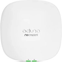

- ARUBA INSTANT ON 2.2.0 USER GUIDE
- COPYRIGHT INFORMATION
- OPEN SOURCE CODE
- CONTENTS
- REVISION HISTORY
- ABOUT THIS GUIDE
- ARUBA INSTANT ON SOLUTION
- WHATS NEW IN THIS RELEASE
- ARUBA INSTANT ON DEPLOYMENT CONCEPTS
- PROVISIONING YOUR ARUBA INSTANT ON DEVICES
- ARUBA INSTANT ON USER INTERFACE
- MONITORING SITE HEALTH
- VIEWING AND UPDATING INVENTORY
- CONFIGURING NETWORKS
- ANALYZING APPLICATION USAGE
- MANAGING CLIENTS
- MANAGING YOUR ACCOUNT
- MANAGING AP FIRMWARE UPGRADES
- TROUBLESHOOTING
- INTENDED AUDIENCE
- RELATED DOCUMENTS
- CONTACTING SUPPORT
- KEY FEATURES
- SUPPORTED DEVICES
- INDOOR INSTANT ON ACCESS POINTS
- OUTDOOR INSTANT ON ACCESS POINTS
- INSTANT ON SWITCHES
- NEW FEATURES AND HARDWARE PLATFORMS
- INSTANT ON WLAN FEATURES
- INSTANT ON WIRED FEATURES
- WIRELESS DEPLOYMENT—ACCESS POINT ONLY
- WIRED DEPLOYMENT—SWITCH ONLY
- WIRED AND WIRELESS DEPLOYMENT—ACCESS POINT AND SWITCH
- DOWNLOADING THE MOBILE APP
- MOBILE OS REQUIREMENTS
- SETTING UP YOUR WIRELESS NETWORK
- SETTING UP YOUR WIRED NETWORK
- AP CONFIGURATION MODES
- PRIVATE NETWORK MODE
- PRE-REQUISITES
- CONFIGURING YOUR INSTANT ON DEVICES IN PRIVATE NETWORK MODE
- ROUTER MODE
- CONFIGURING YOUR INSTANT ON DEVICE IN ROUTER MODE
- LOCAL MANAGEMENT FOR SWITCHES
- SWITCH PROVISIONING USING THE LOCAL WEBUI
- IP ASSIGNMENT FOR ACCESS POINTS
- SETTING UP WAN CONNECTIVITY FOR YOUR NETWORK
- DISCOVERING AVAILABLE DEVICES
- BLE TROUBLESHOOTING
- MULTIPLE SITES
- ACCOUNT MANAGEMENT
- SETUP A NEW SITE
- SIGN OUT
- DEPLOYING MULTICAST SHARED SERVICES
- EXAMPLES
- ACCESSING ARUBA INSTANT ON APPLICATION
- BROWSER REQUIREMENTS
- CREATE AN INSTANT ON ACCOUNT
- LOGGING IN TO INSTANT ON
- RESETTING YOUR ACCOUNT PASSWORD
- MANAGING SITES REMOTELY
- USERNAME AND PASSWORD MANAGEMENT
- USING THE INSTANT ON USER INTERFACE
- OPENING A MODULE
- CLOSING A MODULE
- SITE MANAGEMENT
- ADMINISTRATION
- TIME ZONE
- GUEST PORTAL
- SOFTWARE UPDATE
- ADMINISTRATION SETTINGS
- MODIFYING THE ARUBA INSTANT ON SITE NAME
- ADDING SECONDARY ACCOUNTS
- CHANGING YOUR SECONDARY ACCOUNT
- TRANSFERRING ACCOUNT OWNERSHIP
- TIME ZONE SETTINGS
- SETTING A LOCAL TIME ZONE
- ABOUT SOFTWARE
- ALERTS
- VIEWING ALERT HISTORY
- ADDING A DEVICE
- TYPES OF DEVICES
- EXTENDING YOUR NETWORK
- EXTEND USING A CABLE
- EXTEND OVER THE AIR
- INSTANT ON AP WIRELESS ACCESS POINT PLACEMENT GUIDELINES
- DEPLOYMENT SCENARIOS FOR OUTDOOR ACCESS POINTS
- SCENARIO 1: PROVISION A SITE ON THE OUTDOOR AP CHANNEL
- SCENARIO 2: NEW SITE OR EXISTING SITE WITH NO OUTDOOR MESH POINTS
- SCENARIO 3: EXISTING SITES WITH MESH OUTDOOR ACCESS POINTS
- SCENARIO 4: DELETING LAST OUTDOOR MESH POINT
- RADIO MANAGEMENT
- ACCESS POINT LIGHTS
- LOOP PROTECTION
- ARUBA PROPRIETARY MECHANISM
- RAPID SPANNING TREE PROTOCOL (RSTP)
- POWER SCHEDULE
- DNS
- IDENTIFICATION
- RADIOS
- CONNECTIVITY
- PORTS
- CONNECTED CLIENTS AND DEVICES
- ACTIONS
- LOCATE
- RESTART
- REMOVE FROM INVENTORY
- ROUTER DETAILS
- AUTHENTICATION AND SECURITY
- INCLUDED NETWORKS
- CLIENTS AND DEVICES CONNECTED TO THIS PORT
- NETWORKS
- REPLACING A ROUTER FROM THE INVENTORY
- SWITCH DETAILS
- DEVICE NAME
- LOCAL NETWORK IP
- POWER OVER ETHERNET (POE)
- LAN IP
- ROUTING
- POWER MANAGEMENT
- LINK AGGREGATION
- AGGREGATION MODE
- CLIENTS AND DEVICES CONNECTED ON THIS LINK AGGREGATION
- SWITCH TO LOCAL MANAGEMENT
- TOPOLOGY
- AUTO-DETECTION AND AUTO-CONFIGURING OF SWITCH PORTS
- EMPLOYEE NETWORK
- CLICK SAVE
- OPTIONS
- SHOW NETWORK
- WI-FI
- OPTIMIZE FOR VIDEO STREAMING
- LIMIT BANDWIDTH USAGE
- IP AND NETWORK ASSIGNMENT
- RADIO
- EXTEND 2.4 GHZ RANGE
- SCHEDULE
- CREATING AN ACCESS SCHEDULE FOR AN EMPLOYEE NETWORK
- NETWORK ACCESS
- SHARED SERVICES
- LIST OF SUPPORTED SERVICES
- APPLICATIONS
- GUEST NETWORK
- WI-FI ENHANCED OPEN (OWE)
- CONFIGURING GUEST PORTAL
- CONFIGURING CAPTIVE PORTAL
- CONFIGURING INTERNAL CAPTIVE PORTAL
- CONFIGURING EXTERNAL CAPTIVE PORTAL
- USING THIRD-PARTY CAPTIVE PORTAL PROVIDERS
- CLICK APPLY CHANGES
- CUSTOMIZING THE CAPTIVE PORTAL PAGE
- CONFIGURING FACEBOOK WI-FI
- CONFIGURING THE FACEBOOK WI-FI SERVICE
- WIRED NETWORK
- MODIFYING THE NETWORK NAME OR VLAN ID
- ENABLING OR DISABLING A WIRED NETWORK
- IMPORTANT POINTS TO NOTE
- CONFIGURING A VOICE NETWORK
- ENERGY EFFICIENT ETHERNET
- NETWORK SECURITY
- DHCP SNOOPING
- ARP ATTACK PROTECTION
- VIEWING APPLICATION INFORMATION
- APPLICATIONS VISIBILITY AND CONTROL
- FILTERING APPLICATION INFORMATION IN THE WEB APPLICATION
- ANALYZING APPLICATION USAGE DATA BY CATEGORY
- SORTING APPLICATION INFORMATION IN THE WEB APPLICATION
- APPLICATIONS CHART
- APPLICATIONS LIST
- VIEWING AND BLOCKING APPLICATION ACCESS
- VIEWING APPLICATIONS
- BLOCKING APPLICATION ACCESS
- VIEWING CLIENTS IN THE SITE
- CONNECTED CLIENTS
- BLOCKING A WIRELESS CLIENT
- SORTING CLIENT INFORMATION IN THE WEB APPLICATION
- BLOCKED CLIENTS
- UNBLOCKING A BLOCKED CLIENT
- VIEWING CLIENT DETAILS
- WIRED CLIENTS
- WIRED CLIENT DETAILS
- MODIFYING ADMINISTRATOR ACCOUNT INFORMATION
- NOTIFICATIONS
- ENABLING OR DISABLING ALERT NOTIFICATIONS
- ALERT CATEGORIES
- CONNECTION PROBLEM
- DEVICE PROBLEM
- DEVICE CAPACITY EXCEEDED
- NEW SOFTWARE AVAILABLE
- UPGRADING THE FIRMWARE FOR AN INSTANT ON AP OR SWITCH
- INSTANT ON IMAGE SERVER
- UPDATING THE SOFTWARE IMAGE ON AN INSTANT ON SITE
- VERIFYING CLIENT CONNECTIVITY DURING UPGRADE
- UPGRADE FAILURE
- INSTANT ON MOBILE APP COMPATIBILITY
Brand : HP
Model : Aruba Instant On AP22
Category : Access Point