
WTEES 2053 VINIDOR - Wine cellar LIEBHERR - Free user manual and instructions
Find the device manual for free WTEES 2053 VINIDOR LIEBHERR in PDF.
| Product type | Wine cellar |
| Brand | LIEBHERR |
| Model | WTEES 2053 VINIDOR |
| Capacity | 64 Bordeaux bottles (0.75 L) |
| Number of temperature zones | 2 (independent) |
| Adjustable temperature range | 5 °C to 20 °C |
| Recommended temperature | 8 °C to 12 °C |
| Refrigerant | R 600a (quantity indicated on the rating plate) |
| Climate class | SN, N, ST, T (from 10 °C to 43 °C) |
| Door alarm | Yes (after 60 s) |
| Temperature alarm | Yes |
| Child safety | Yes (keypad lock) |
| Fan | Yes (increases humidity) |
| Active carbon filter | Yes (annual replacement) |
| Lighting | LED, with dim mode |
| Shelves | Wood, including one folding shelf |
| Door reversibility | Yes |
| Power supply | 220-240 V, 50 Hz (see rating plate) |
| Maintenance | Clean with a soft cloth and mild detergent; do not use steam cleaner |
| Spare parts | Carbon filter, wooden shelves, LED bulbs (service) |
Frequently Asked Questions - WTEES 2053 VINIDOR LIEBHERR
User questions about WTEES 2053 VINIDOR LIEBHERR
0 question about this device. Answer the ones you know or ask your own.
Ask a new question about this device
Download the instructions for your Wine cellar in PDF format for free! Find your manual WTEES 2053 VINIDOR - LIEBHERR and take your electronic device back in hand. On this page are published all the documents necessary for the use of your device. WTEES 2053 VINIDOR by LIEBHERR.
USER MANUAL WTEES 2053 VINIDOR LIEBHERR
1 Appliance at a glance. 2
1.1 Description of appliance and equipment 2
1.2 Range of appliance use 2
1.3 Conformity 2
1.4 Saving energy.. 3
2 General safety information. 3
3 Controls and displays. 3
3.1 Operating and control elements 3
3.2 Temperature display 3
4 Putting into operation 4
4.1 Transporting the appliance 4
4.2 Installing the appliance.. 4
4.3 Changing over the door hinges 4
4.4 Fitting 6
4.5 Disposing of packaging 8
4.6 Connecting the appliance 8
4.7 Switching on the appliance 8
5 Control 8
5.1 Brightness of the temperature display 8
5.2 Childproofing 8
5.3 Door alarm.. 8
5.4 Temperature alarm.. 9
5.5 Storing wine bottles 9
5.6 Setting the temperature in the wine zone.. 9
5.7 Fan 9
5.8 Dim mode 9
5.9 Labels 9
5.10 Wooden shelf. 10
6 Maintenance. 10
6.1 Replacing the activated charcoal filter 10
6.2 Cleaning the appliance.. 10
6.3 Customer service 10
7 Malfunction 11
8 Decommissioning. 11
8.1 Switching off the appliance 11
8.2 Taking the appliance out of service 11
9 Disposing of the appliance. 12
The manufacturer works constantly on the further development of all the types and models. Therefore please understand that we have to reserve the right to make design, equipment and technical modifications.
To get to know all the benefits of your new appliance, please read the information contained in these instructions carefully.
Instructions for action are marked with a , the results of action are marked with a .
1 Appliance at a glance
1.1 Description of appliance and equipment
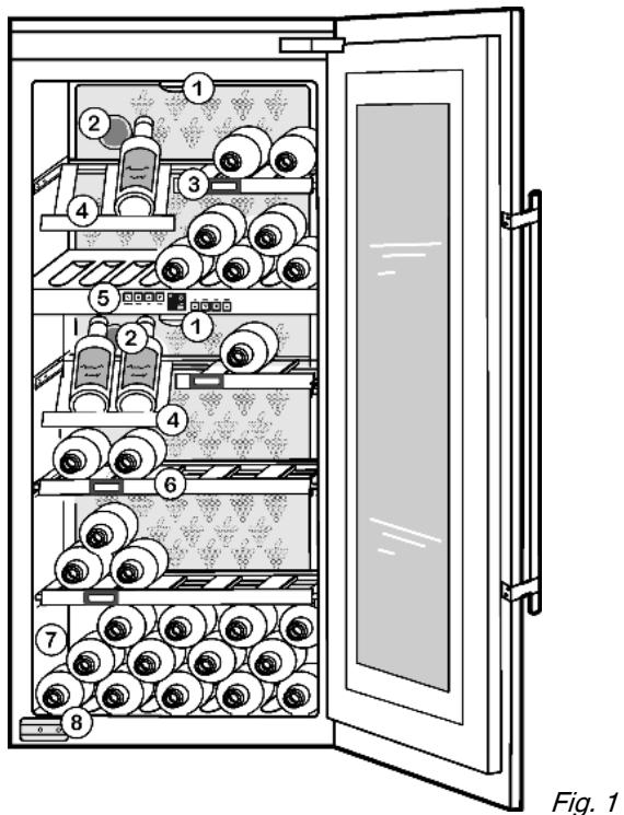
(1) Lighting
(2) Activated charcoal filter
(3) Label
(4) Wooden shelf, folding
Fig. 1
(5) Operating and display elements
(6) Wooden shelf
(7) Type plate
(8) Transit supports
1.2 Range of appliance use
The appliance is suitable solely for storing wine and food in a domestic environment or similar. This includes use in, for example
- in staff kitchenettes, bed and breakfast establishments,
- by guests in country homes, hotels, motels and other forms of accommodation,
- in catering and similar services in the wholesale trade
The appliance is set to operate within specific ambient temperature limits according to its climate rating. The correct climate rating for your appliance is indicated on the type plate.
Compliance with the ambient temperatures indicated is required, otherwise the cooling performance is reduced.
Note
| Climate rating | for ambient temperatures of |
| SN | 10 °C to 32 °C |
| N | 16 °C to 32 °C |
| ST | 16 °C to 38 °C |
| T | 16 °C to 43 °C |
1.3 Conformity
The refrigerant circuit has been tested for leaks. When installed, this appliance complies with the relevant safety provisions and EC directives 2006/95/EC and 2004/108/EC.
As energy efficiency guidelines for multi-temperature wine cabinets are not available, wine compartments are evaluated as cellar temperature compartments for energy efficiency class allocation.
1.4 Saving energy
- Always ensure good ventilation. Do not cover ventilation openings or grille.
- Do not place appliance in areas of direct sunlight or next to a stove, heater or similar object.
- The energy consumption depends on the installation conditions, e.g. the ambient temperature (see 1.2).
- Keep the time the appliance is open to a minimum.
- The lower the temperature setting, the higher the power consumption.
2 General safety information
Danger for the user:
- This appliance is not designed for persons (including children) with physical, sensory or mental impairment or persons not having sufficient experience and knowledge, unless they are instructed in the use of the appliance and are initially supervised by a person responsible for their safety. Keep children under supervision to ensure they do not play with the appliance.
- In case of a fault, pull out the mains plug (not by pulling the connecting cable) or switch off the fuse.
- Have any repairs to or intervention in the appliance, and any change of the mains power cable, carried out by the customer service only or by other specialised personnel trained for the purpose.
- When disconnecting the appliance from the supply, always take hold of the plug. Do not pull the cable.
- Install and connect the appliance only as instructed.
- Please keep these instructions in a safe place and pass them on to any subsequent owners.
- Special-purpose lamps (incandescent lamps, LEDs, fluorescent tubes) in the appliance serve to illuminate the appliance interior and are not suited for room illumination.
Fire hazard:
-
The refrigerant R 600a is environmentally friendly but flammable. Escaping refrigerant may ignite.
-
Do not damage the refrigerant circuit pipes.
- Do not allow naked flames or ignition sources to enter the appliance.
- Do not use any electrical appliances in the interior (e.g. steam cleaners, heaters, ice cream maker etc.).
-
If refrigerant escapes: eliminate naked flames or sources of ignition from the vicinity. Pull out the power plug. Ventilate the area well. Notify customer service.
-
Do not store explosives or sprays using combustible propellants such as butane, propane, pentane, etc. in the appliance. Respective spray cans can be identified by reference to the contents printed on the can or by a flame symbol. Gases possibly escaping may ignite due to electrical components.
- Only store high-percentage alcohol in tightly sealed, upright containers. Alcohol possibly escaping may ignite due to electrical components.
Danger of tipping and falling:
- Do not misuse the plinth, drawers, doors etc. as a step or for support. This applies particularly to children.
Danger of food poisoning:
- Do not consume food which has been stored too long.
Danger of frostbite, numbness and pain:
- Avoid lasting skin contact with cold surfaces or refrigerated/ frozen food or take protective steps, e.g. wear gloves. Do
not consume ice cream, water ice or ice cubes immediately and do not consume them too cold.
Risk of crushing
- Do not reach into the soft stop mechanism. Fingers may be trapped when the door is closed.
Please observe the specific information in the other sections:
| ! | DANGER | identifies a situation involving direct danger which, if not obviated, may result in death or severe bodily injury. |
| ! | WARNING | identifies a dangerous situation which, if not obviated, may result in death or severe bodily injury. |
| ! | CAUTION | identifies a dangerous situation which, if not obviated, may result in minor or medium bodily injury. |
| NOTICE | identifies a dangerous situation which, if not obviated, may result in damage to property. | |
| Note | identifies useful information and tips. |
3 Controls and displays
3.1 Operating and control elements
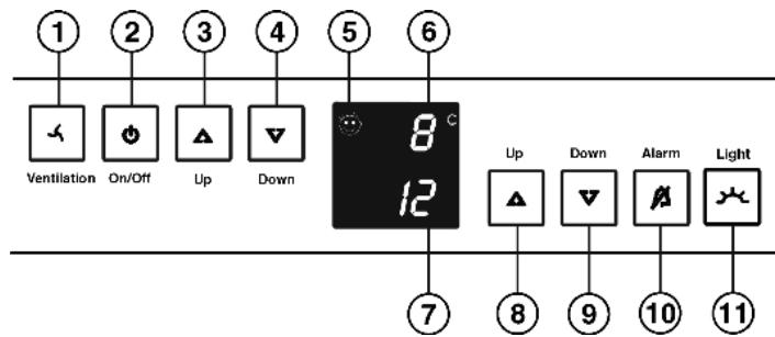
Fig. 2
(1) Fan button
(2) On/Off button
(3) Up setting button, upper wine zone
(4) Down setting button, upper wine zone
(5) Child-proofing symbol
(6) Upper wine zone temperature display
(7) Lower wine zone temperature display
(8) Up setting button, lower wine zone
(9) Down setting button, lower wine zone
(10) Alarm button
(11) Light button
3.2 Temperature display
The following are displayed in normal operation:
- the average wine cabinet temperature
The temperature display flashes:
- the temperature setting is being changed
- the wine cabinet temperature is too cold/too warm
The following displays indicate malfunction. Possible causes and corrective action (see Malfunction).
- F0 to FS
GB
4 Putting into operation
4.1 Transporting the appliance

CAUTION
Risk of injury and danger of damage as a result of incorrect transport!
Transport the appliance in a packed condition.
Transport the appliance upright.
Do not transport the appliance without assistance.

WARNING
Risk of injury due to broken glass!
In case of transport at an altitude of over 1500m the glass panes of the door may break. The fragments have sharp edges and may cause serious injury.
Take appropriate protective action.
NOTICE
Risk of damage to the door!
The glass door is heavy. If insufficiently secured, the hinges and door may suffer damage.
Transport the appliance only with shipping braces in place.
4.2 Installing the appliance
In the event that the appliance is damaged, contact the supplier immediately before connecting to the mains.
The floor at the site must be flat and level.
Do not install the appliance in a location where it is exposed to direct radiation of the sun, next to a cooker, heater and similar.
Do not install the appliance without assistance.
Standard EN 378 specifies that the room in which you install your appliance must have a volume of 1m^2 per 8g of R 600a refrigerant used in the appliance. If the room in which the appliance is installed is too small, a flammable gas-air mixture may form in the event of a leakage in the refrigeration circuit. The quantity of refrigerant used in your appliance is indicated on the type plate on the inside of the appliance.
Fit the appliance in stable kitchen units only.
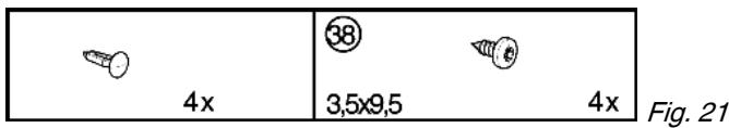
The following ventilation gaps must be observed:
The depth of the ventilation channel at the rear of the unit must be at least 38mm
There must be a ventilation space of at least 200cm^2 in the plinth and at the top of the unit.
- Basically the principle applies: the larger the ventilation space, the more energy-saving the appliance is in operation.

WARNING
Fire hazard due to dampness!
If live parts or the mains lead become damp this may cause short circuits.
The appliance is designed for use in enclosed areas. Do not operate the appliance outdoors or in areas where it is exposed to splash water or damp conditions.

WARNING
Fire hazard due to refrigerant!
The refrigerant R 600a is environmentally friendly but flammable. Escaping refrigerant may ignite.
Do not damage the piping of the refrigeration circuit.

WARNING
Fire hazard and danger of damage!
- Do not place appliances emitting heat e.g. microwaves, toasters etc. on the appliance!
Detach the connecting cable from the rear of the appliance, removing the cable holder at the same time because otherwise there will be vibratory noise!
After installation:
Remove the protective film from the outside of the appliance.
Remove all transit supports.
Dispose of packaging material (see 4.5).
Note
Clean the appliance (see 6.2).
If the appliance is installed in a very damp environment, condensate may form on the outside of the appliance.
Always see to good ventilation at the installation site.
4.3 Changing over the door hinges
Ensure that the following tools are to hand:
Flat-blade screwdriver
□ Pliers
Crosstip screwdriver
Torx screwdriver 15
- Torx screwdriver 20
- Torx screwdriver 25
Turn in the adjustable-height feet all the way.
Pull out the plug.
Open the door.

WARNING
Risk of injury and damage due to broken glass!
The glass door is heavy. If it drops, the glass pane may shatter.
Safeguard the door properly when it is removed!
Detachment of the door has to be carried out by two persons.
Lay down the door on a soft mat.
4.3.1 Removing the door and soft stop mechanism
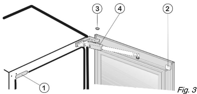
Lift off cover Fig. 3 (1) and cover Fig. 3 (2) as well as stopper Fig. 3 (3).
Push cover of soft stop mechanism Fig. 3 (4) back and detach it.

CAUTION
Danger of injury by the soft stop mechanism! If the soft stop mechanism contracts and strikes the appliance, fingers may get caught and the appliance may be damaged.
- Keep a firm hold on the soft stop mechanism.
Lift the soft stop mechanism Fig. 4 (5) off the ball journal Fig. 4 (6). Carefully lift the spring using a screwdriver in order to detach the spring clip Fig. 4 (7).
- Carefully swivel the soft stop mechanism to the appliance.
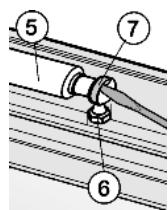
Fig. 4
Carefully lift the cover of the turn hinge Fig. 5 (8) using a screwdriver and slide it forwards.
Set the soft stop mechanism at an angle away from the appliance and remove the cover Fig.5(8).
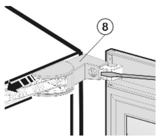
Fig. 5
Unscrew the front screw Fig. 6 (10) from the bearing of the soft stop mechanism Fig. 6 (11).
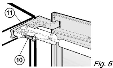

CAUTION
Danger of injury due to the spring tension acting on the soft stop mechanism.
Secure the soft stop mechanism.
Set the soft stop mechanism Fig. 7 (5) at an angle and carefully lay it on the front face of the appliance.
Unscrew the middle screw Fig. 7 (12) from the bearing of the soft stop mechanism Fig. 7 (11).
Remove the soft stop mechanism and set it aside.
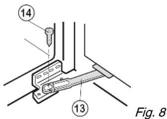
To detach the stop Fig.8 (13):undo the screw Fig.8(14).
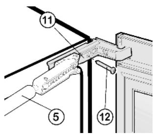
Fig. 7

CAUTION
Risk of injury if the door tips!
Take good hold of the door.
Set down the door carefully.
To unscrew the top turn hinge Fig. 9 (9): undo the screw Fig. 9 (15).
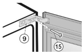
Fig. 9
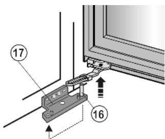
Fig. 10
At the bottom, lift the door off the pin Fig. 10 (16) of the lower turn hinge Fig. 10 (17) and set it aside.
Transfer the bearing pin Fig. 10 (16) in the turn hinge and screw it firmly into place (with 4 Nm).
If the handle is already fastened:
detach the handle.
4.3.2 Transferring the bearing parts
To raise the bearing pin Fig. 11 (18): Move turn hinge Fig. 11 (9) up and down.
Using pliers, pull out the bearing pin Fig. 11 (18) and set it aside.
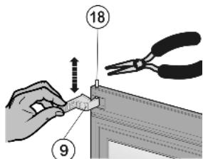
Fig. 11
Transfer the stop Fig. 12 (13) to the opposite side and screw it firmly into place (with 2 Nm).
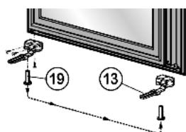
Fig. 12
- Check whether there is a white plastic sleeve in the door bearing on the opposite side. If not*: Draw the plastic sleeve Fig. 12 (19) out of the door bearing and insert it snugly at the opposite side.
Detach the transit support of the door Fig. 13 (20).
Do not dispose of the transit support of the door.
Unscrew the lower bearing bracket Fig. 13 (17).
Screw the bottom turn hinge Fig. 13 (17) firmly into place on the opposite side, using the third and sixth oblong hole counted from the outside(with 4Nm ).

Fig. 13
If the appliance is transported again, the transit support has to be re-fitted:
Screw down transit support of the door Fig. 13 (20) at the opposite side.
Turn the top turn hinge Fig. 14 (9) through 180^ and screw it firmly into place on the opposite side with the screw Fig. 14 (15)(with 4 Nm). Butt the turn hinge against the side wall of the appliance.
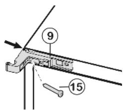
Fig. 14
4.3.3 Re-fitting the door and soft stop mechanism

CAUTION
Danger of injury due to the spring tension acting on the soft stop mechanism.
Secure the soft stop mechanism.
Angle the soft stop mechanism Fig. 15 (5) in such a way that the screw Fig. 15 (12) can be screwed in. Firmly tighten the screw (with 4 Nm).
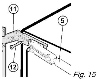
Then angle the soft stop mechanism in such a way that the front screw Fig. 16 (10) can be screwed in. Firmly tighten the screw (with 4Nm ).
- Carefully lay the soft stop mechanism Fig. 7 (5) on the front face of the appliance.
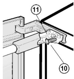
Fig. 16
At the bottom, place the door on the bearing pin Fig. 17(16).
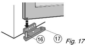
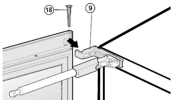
Fig. 18
At the top, move the door over the turn hinge Fig. 18 (9) and insert the Fig. 18 (18) bearing pin.
Re-engage the cover of the turn hinge Fig. 5 (8).
Transfer the ball stud Fig. 4 (6) and tighten it firmly (with 2 Nm).
Engage the soft stop mechanism with the ball journal.
Attach the cover Fig. 3 (4) of the soft stop mechanism and slide it forwards.
Screw the stop Fig. 19 (13) firmly into place, through the white slide Fig. 19 (23), using the screw Fig. 19 (14) (with 4 Nm).
Re-fit all the cover parts and stoppers at the opposite side.
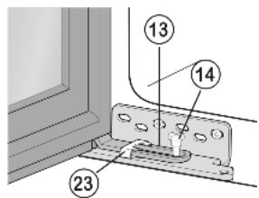
Fig. 19

WARNING
Risk of injury due to the door dropping out!
If the bearing parts are not screwed into place firmly enough, the door may drop out. This may lead to severe injuries. What is more, the door may not close and therefore the appliance may fail to cool properly.
Screw on the bearing parts tightly as stated in the text.
Check all of the screws and retighten if necessary.
4.4 Fitting
All the fasteners accompany the appliance.

Ensure that the following tools are to hand:
Crosstip screwdriver
Torx screwdriver 10
Torx screwdriver 15
Torx screwdriver 25
Torx screwdriver 30
Spanner
The shelf and side walls of the unit must be at right-angles to one another. Align the unit with a spirit level and an angle. If necessary, level out by building up from underneath.
Check installation dimensions:
4.4.1 Installing the appliance
NOTICE
Risk of damage to the door!
- Detach door transit supports only when the appliance is slid fully into the recess.
Detach the connecting cable from the rear of the appliance, removing the cable holder because otherwise there will be vibratory noise!
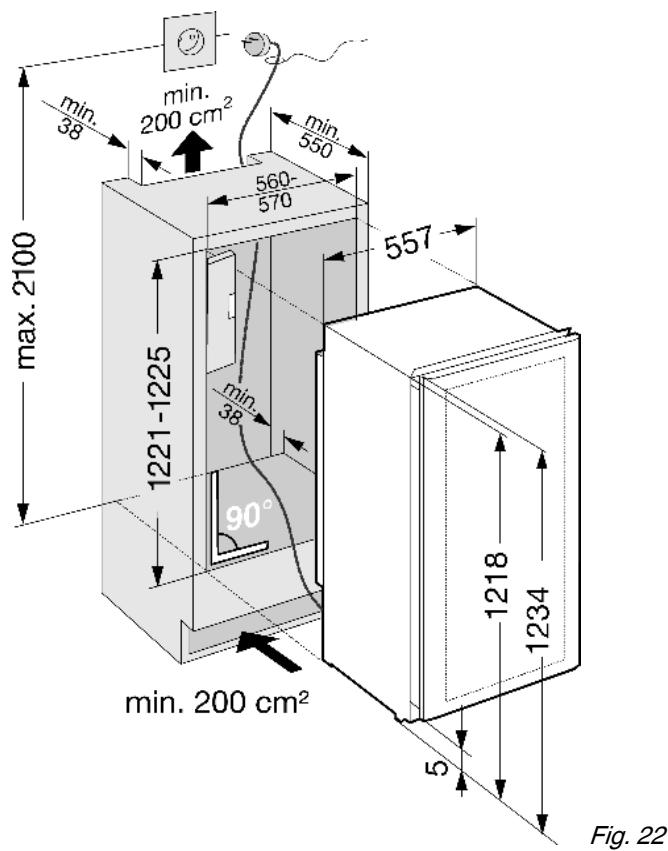
Lay the connecting cable with the help of a string in such a way that the appliance can be easily connected after fitting.
▶ Slide the appliance 2/3 of the way into the recess.

Turn in the adjustable-height feet all the way.
Fix the equaliser trim Fig. 24 (30) with screws Fig. 24 (31) in the pilot holes in the ceiling of the appliance.
Strip the protective film off the cover trim Fig. 25 (32).
Adhesively affix the cover trim Fig. 25 (32) on the handle side so as to be flush with the front of the side wall of the appliance.
If necessary, shorten the cover trim to recess height.
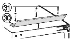
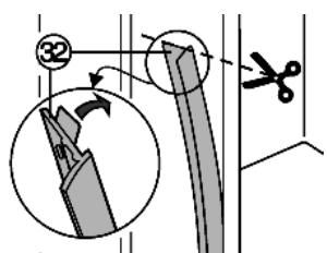
Fig. 24
Fig. 25
For 16 mm thick unit walls (568 mm wide recess):
Press spacer Fig. 26 (33) onto the turn hinge Fig. 26 (9) in the area of the slot. For 19 mm thick unit walls (562 mm wide recess):
the spacer is not needed.
Push the appliance into the recess until the lower turn hinge Fig. 27 (17) abuts the end face of the unit wall.
The turn hinge Fig. 27 (17) bears on the floor of the recess.
Detach the Fig. 28 (20) transit support.
If the appliance is transported again, the transit support has to be re-fitted:
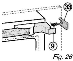
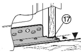
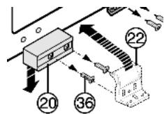
Fig. 27
Fig. 28
Do not dispose of the transit support for the door.
Screw plastic bracket Fig. 29 (22) onto the handle side of the appliance with M5 screws Fig. 29 (36).
Align the plastic bracket Fig. 29 (22) so as to flush with the front edge of the unit floor.
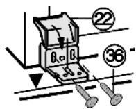
Fig. 29
At the bottom of the turn hinge Fig. 30 (17), measure the distance (X) from the front edge of the unit side wall to the appliance.
Check whether the measurement made is the same all the way round, otherwise the door may not close properly.
If necessary, extend the adjustable-height foot on the handle side so as to make up for any unevenness of the floor.
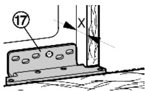
Fig. 30

CAUTION
Danger of injury by the soft stop mechanism! If the soft stop mechanism contracts and strikes the appliance, fingers may get caught and the appliance may be damaged. Keep a firm hold on the soft stop mechanism.
Lift the soft stop mechanism Fig. 31 (5) off the ball journal Fig. 31 (6). Carefully lift the spring using a screwdriver in order to detach the spring clip Fig. 31 (7).
Carefully swivel the soft stop mechanism to the appliance.
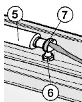
Fig. 31
To fix appliance at top: Press appliance firmly against the wall of the unit and fasten it by passing a Spax screw Fig. 32 (34) through the turn hinge Fig. 32 (9).
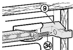
Fig. 32
To fix appliance at bottom: Fasten the appliance with screws Fig. 33 (17) through the turn hinge Fig. 33 (35).
Fasten folding bracket Fig. 33 (22) to the unit base with screws Fig. 33 (35).
Fold down the cover of the folding bracket Fig. 33 (22).
Fasten the equaliser trim Fig. 34 (30) to the ceiling of the unit from underneath using two screws Fig. 34 (37).
Check that all the screw fittings are tight.
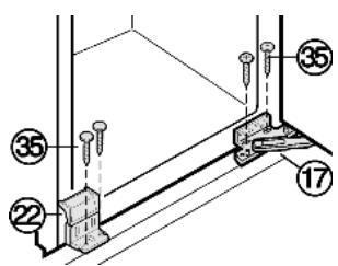
Fig. 33
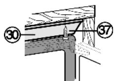
Fig. 34
At the bottom of the turn hinge Fig. 30 (17) again measure the distance (X) from the front edge of the unit side wall to the appliance.
- Check whether the measurement made is the same all the way round, otherwise the door may not close properly.
Re-align unit and appliance, if necessary. For initial assembly:
Take the handle out of the packaging of the ceiling protection and fit it to the inside of the door with 4 screws Fig.35 (38).
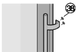
Fig. 35
Re-attach soft stop mechanism Fig. 31 (5) in reverse order.
4.5 Disposing of packaging

WARNING
Danger of suffocation due to packing material and plastic film!
Do not allow children to play with packing material.
The packaging is made of recyclable materials:
- corrugated board/cardboard
- expanded polystyrene parts
polythene bags and sheets
polypropylene straps - nailed wooden frame with polyethylene panel*
Take the packaging material to an official collecting point.

4.6 Connecting the appliance
NOTICE
Risk of damage to the electronic control system!
Do not use stand-alone inverters (conversion of d.c. to a.c./ three-phase) or energy saving plugs.

WARNING
Fire and overheating hazard!
Do not use extension cables or multiple socket outlets.
The type of current (alternating current) and voltage at the installation site have to conform with the data on the type plate (see Appliance at a glance).
Connect the appliance only with a properly installed socket outlet with earthing contact. The socket outlet must be fused with 10 A or higher.

Check the electrical connection.
Plug in the power plug.
4.7 Switching on the appliance
Press On/Off button Fig. 2 (2).
The temperature display and the alarm button flash until the set temperature is reached.
5 Control
5.1 Brightness of the temperature display
You can adjust the brightness of the temperature display to the light conditions of the room in which the appliance is installed.
5.1.1 Adjusting the brightness
The brightness is adjustable between no (no illumination) and h5 (maximum luminosity).
To activate the setting mode: press the fan button Fig. 2 (1) for about 5s.
The fan button Fig. 2 (1) flashes. The display indicates c.
Using the Up setting button, upper wine zone Fig. 2 (3) and Down setting button, upper wine zone Fig. 2 (4) select h.
To confirm: briefly press the fan button Fig. 2 (1).
To set the display brighter: press the Up setting button, upper wine zone Fig. 2 (3).
To set the display darker: press the Down setting button, upper wine zone Fig. 2 (4).
To confirm: briefly press the fan button Fig. 2 (1).
The brightness is adjusted to the new value.
To deactivate the setting mode: press the On/Off button Fig. 2 (2).
-or-
Wait for 5 minutes.
The temperature is indicated again in the temperature display.
5.2 Child proofing
The child-proofing function enables you to make sure that the appliance is not inadvertently switched off by playing children.
5.2.1 Setting the child-proofing function
To activate the setting mode: press the fan button Fig. 2 (1) for about 5s.
The fan button flashes. The display indicates c.
Briefly press the fan button Fig. 2 (1) to confirm.
To switch on: using the Up setting button, upper wine zone Fig. 2 (3) or Down setting button, upper wine zone Fig. 2 (4) select cl.
To switch off: using the Up setting button, upper wine zone Fig. 2 (3) or Down setting button, upper wine zone Fig. 2 (4) select c0.
To confirm: press the fan button Fig. 2 (1).
The child-proofing function is switched on when the childproofing symbol Fig. 2 (5) shines.
To deactivate the setting mode: press the On/Off button Fig. 2 (2).
-or
Wait for 5 minutes.
The temperature is indicated again in the temperature display.
5.3 Door alarm
If the door is open longer then 60 s, the audible alarm sounds.
The audible alarm is automatically silenced when the door is closed.

5.3.1 Muting the door alarm
The audible alarm can be muted when the door is open. The sound switch-off function is active as long as the door is left open.
Press alarm button Fig. 2 (10).
The door alarm is silenced.
5.4 Temperature alarm
The audible alarm sounds if the wine storage temperature is too warm or too cold.
The temperature display flashes at the same time.
The cause of the temperature being too high may be:
- too much warm ambient air flowed in when rearranging and removing food
- power failure for some time
- the appliance is faulty
The audible alarm is automatically silenced and the temperature display stops flashing when the temperature is sufficiently cold/warm again.
If the alarm status persists: (see Malfunction).
5.4.1 Muting the temperature alarm
The audible alarm can be muted. When the temperature is sufficiently cold again, the alarm function is active again.
Press alarm button Fig. 2 (10).
The audible alarm is silenced.
5.5 Storing wine bottles
64 Bordeaux bottles (0,75 l) can be stored in the wine zone.
- Store white wine only in one compartment and red wine only in the other, since both compartments can be set to independent temperatures.
If possible, lay bottles of the same type of wine side by side on the same grid shelf.
Rearrange bottles as seldom as possible. - Stored open bottles on the folded down wooden grid shelf.
To fold down the wooden grid shelf: press the lock under the trim sideways.
The wooden grid shelf folds down.
5.6 Setting the temperature in the wine zone
The appliance is pre-set for normal operation. The temperature can be set from 20^ to 5^ , the recommended temperatures are 8^ to 12^ .
The wine zone is divided into two wine compartments, which can be set to different temperatures, as needed.
To set the temperature warmer: press the Up setting button, upper wine zone Fig. 2 (3) or Up setting button, lower wine zone Fig. 2 (8).
To set the temperature colder: press the Down setting button, upper wine zone Fig. 2 (4) or Down setting button, lower wine zone Fig. 2 (9).
To change the temperature in 1^ steps: briefly press the button.
-or-
To change the temperature continuously: hold down the button.
During setting the new value is displayed flashing.
The actual temperature is displayed about 5 s after the last press of a button. The temperature slowly adjusts to the new value.
5.7 Fan
When the fan runs, the relative humidity in the interior increases so that the cork does not dry out.
When the fan is activated, the energy consumption increases. To save energy, the fan switches off automatically when the door is open.
The fan button Fig. 2 (1) shines.
The fan always runs. The humidity is high.
Briefly press the fan button Fig. 2 (1).
The fan button Fig. 2 (1) does not shine.
The fan runs only when this is necessary for temperature control. The humidity is low.
5.8 Dim mode
For glazed door models you can set the dim mode of the light, i.e. the intensity with which the light is to shine after the door has closed.
5.8.1 Setting the dim mode
Note
When the dim mode is deactivated, the light becomes slowly darker after the door has closed and then goes out.
Briefly press the Light button Fig. 2 (11).
The Light button Fig. 2 (11) shines. The dim mode is activated.
The settings apply to all wine compartments.
For a brighter light adjustment: press Light button Fig. 2 (11) and Up setting button, lower wine zone Fig. 2 (9) at the same time.
For a darker light adjustment: press Light button Fig. 2 (11) and Down setting button, lower wine zone Fig. 2 (8) at the same time.
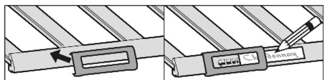
5.9 Labels
You can note down on the labels the type of wine stored in the respective compartment. Additional labels can be obtained from your specialist dealer.
5.9.1 Labelling
5.10 Wooden shelf
Pay attention that the wooden shelf does not get caught on the rear hook.
To remove the folding wooden shelf: lift it off the pull-out rail and draw it forwards.
To insert the wooden folding shelf: slide it under the rear hook and press onto the rails so that they audibly snap into place.
To insert other wooden shelves: place on the rails.
6 Maintenance
6.1 Replacing the activated charcoal filter
The activated charcoal filter ensures ideal air quality and should therefore be replaced annually. It can be ordered from a specialised dealer.
Each wine zone is equipped with an activated charcoal filter of its own.
Take the activated charcoal filter by the grip.
Turn the activated charcoal filter through 90^ to the right or left Fig.361
Remove Fig. 36 (2) the activated charcoal filter.
Insert the new activated charcoal filter with the grip in an upright position.
Turn the new activated charcoal filter through 90^ to the right or left Fig.361) until it snaps into place.
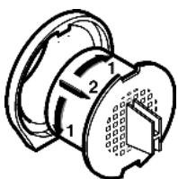
Fig. 36
6.2 Cleaning the appliance
Before cleaning:

CAUTION
Risk of injury and damage as a result of hot steam! Hot steam may damage the surfaces and cause burns.
Do not use any steam cleaners!
NOTICE
Incorrect cleaning damages the appliance!
Do not use cleaning agents in concentrated form.
Do not use any scouring or abrasive sponges or steel wool.
Do not use any cleaning agents containing sand, chloride, chemicals or acid.
Do not use chemical solvents.
- Do not damage or remove the type plate on the inside of the appliance. It is important for the customer service.
Do not pull off, bend or damage cables or other components.
- Do not allow any cleaning water to enter the drain channel, ventilation grille or electrical parts.
Empty the appliance.
Pull out the plug.
- Use soft cleaning cloths and a multi-purpose cleaning agent with neutral pH value.
- Only use food compatible cleaning and care agents on the inside of the appliance.
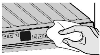
Outside surfaces and interior:
Clean the glass door with a standard glass cleaning agent and a soft cloth.
Clean the plastic surfaces, outside and inside, by hand using lukewarm water and a little washing-up liquid.
Do not apply stainless steel cleaning agent to glass or plastic surfaces to prevent them from being scratched. Darker areas at the beginning and quite an intensive colour of the stainless steel surface are normal.
Wipe the rubber lip of the control panel with a damp cloth and a cleaning agent with neutral pH value.
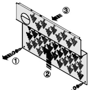
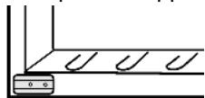
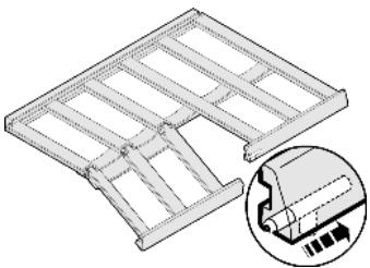
To clean the drain opening:
Remove the wooden grid shelves and detach the pull-out rails.
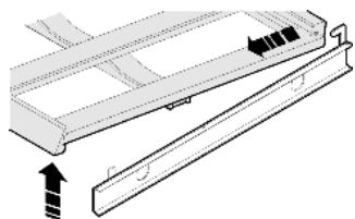
Remove the caps and screws of the metal cover (1) and side them aside.
Raise the metal cover (2) and draw it forwards (3).
To clean the drain opening: remove any deposits with a fine instrument, e.g. a cotton bud.
Items of equipment:
Wipe wooden grid shelves with a dry, lint-free cloth.
Note
Do not clean wooden grid shelves with water and washing-up liquid.
Clean other items of equipment by hand with lukewarm water and a little washing-up liquid.
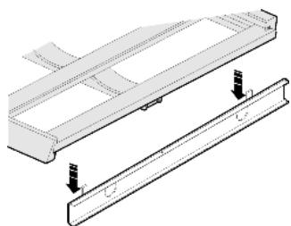
After cleaning:
Wipe dry the appliance and items of equipment.
Connect the appliance and switch it on again.
Put the food back inside.
6.3 Customer service
First check whether you can correct the fault yourself by reference to the list (see Malfunction). If this is not the case, please contact the customer service whose address is given in the enclosed customer service list.

WARNING
Risk of injury if repair work is not carried out professionally!
Have any repairs and action - not expressly specified - on the appliance and mains cable carried out by service personnel only. (see Maintenance)
Read the appliance designation Fig. 37 (1), service No. Fig. 37 (2) and serial No. Fig. 37 (3) off the type plate located inside the appliance on the left-hand side.
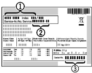
Fig. 37
- Notify the customer service, specifying the fault, appliance designation Fig. 37 (1), service No. Fig. 37 (2) and serial No. Fig. 37 (3).
This will help us to provide you with a faster and more accurate service. - Keep the appliance closed until the customer service arrives.
The food will stay cool longer.
Pull out the mains plug (not by pulling the connecting cable) or switch off the fuse.
7 Malfunction
Your appliance is designed and manufactured for a long life span and reliable operation. If a malfunction nonetheless occurs during operation, check whether it is due to a handling error. In this case you will have to be charged for the costs incurred, even during the warranty period. You may be able to rectify the following faults yourself:
Appliance does not work.
The appliance is not switched on.
Switch on the appliance.
The power plug is not properly inserted in the wall socket.
Check power plug.
The fuse of the wall socket is not in order.
Check fuse.
The compressor runs for a long time.
The compressor switches to a low speed when little cold is needed. Although the running time is increased as a result, energy is saved.
This is normal in energy-saving models.
Excessive noise.
Speed-controlled* compressors may produce varying running noise due to different speed steps.
The sound is normal.
A bubbling and gurgling noise.
This noise comes from the refrigerant flowing in the refrigeration circuit.
The sound is normal.
A quiet clicking noise.
The noise is produced whenever the refrigeration unit (motor) automatically switches on or off.
The sound is normal.
A hum. It is briefly a little louder when the refrigeration unit (the motor) switches on.
→ The refrigeration increases automatically when fresh food has just been placed in the appliance or the door has been left open for a while.
The sound is normal.
→ The ambient temperature is too high.
Solution: (see 1.2)
A low hum.
The sound is produced by air flow noise of the fan.
The sound is normal.
Noise of the soft stop mechanism.
→ The appliance has a high-grade soft stop mechanism as the glass door is heavy. A flow sound or clicking may occur when the door is opened and closed.
The sound is normal.
Mould on the wine bottles.
Similarly as with other forms of storage, a little mould may form depending on the type of adhesive used for the label.
Remove residual adhesive.
The temperature display indicates: F0 to FS.
There is a fault.
Contact the customer service (see Maintenance).
The temperature is not cold enough.
The door of the appliance is not properly closed.
Close the door of the appliance.
Insufficient ventilation.
Clear ventilation grilles.
The ambient temperature is too high.
Solution: (see 1.2).
The appliance was opened too frequently or for too long.
- Wait until the appliance reaches the required temperature itself. If not, contact the customer service. (see Maintenance).
The temperature is incorrectly set.
Set to a colder temperature and check after 24 h.
The appliance is too close to a heat source.
Solution: (see Putting into operation).
The interior light is not on.
→ The appliance is not switched on.
Switch on the appliance.
→ The LED lighting is defective or the cover is damaged:

WARNING
Risk of injury due to electric shock!
Live parts are located under the cover.
Have the LED interior light changed or repaired only by the customer service or by specialized personnel trained for the purpose.

WARNING
Danger of injury due to laser radiation, class 1M.
Do not look inside when the cover is open.
8 Decommissioning
8.1 Switching off the appliance
Press On/Off button Fig. 2 (2) for about 2 s.
The temperature display is dark.
8.2 Taking the appliance out of service
Empty the appliance.
Pull out the power plug.
Clean the appliance (see 6.2).
Leave the door open to prevent odour.

9 Disposing of the appliance
The appliance contains some reusable materials and should be disposed of properly - not simply with unsorted household refuse. Appliances which are no longer needed must be disposed of in a professional and appropriate way, in accordance with the current local regulations and laws.
When disposing of the appliance, ensure that the refrigeration circuit is not damaged to prevent uncontrolled escape of the refrigerant it contains (data on type plate) and oil.
Disable the appliance.
Pull out the plug.
Cut through the connecting cable.