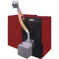
Sun Pellet - Cooker FERROLI - Free user manual and instructions
Find the device manual for free Sun Pellet FERROLI in PDF.


| Product Type | Pellet Cooker |
| Brand | Ferroli |
| Model | Sun Pellet |
| Energy Source | Wood Pellets |
| Heat Output | Approx. 6-12 kW |
| Cooking Surface | Enameled steel top with multiple burners |
| Oven Type | Integrated electric oven (approx. 60 L) |
| Dimensions (W x H x D) | Approx. 100 x 85 x 60 cm |
| Weight | Approx. 120 kg |
| Power Supply | 230 V ~ 50 Hz (for electric components) |
| Pellet Hopper Capacity | Approx. 15-20 kg |
| Autonomy | Up to 24 hours at low power |
| Control System | Digital display with programmable thermostat |
| Safety Features | Overheat protection, child lock, safety thermostat |
| Installation | Must be installed by a qualified professional |
| Maintenance | Daily ash removal; weekly cleaning of combustion chamber |
| Flue Gas Exit | Rear or top, compatible with 80 mm pipes |
| Efficiency | Class A+ energy rating |
| Spare Parts Availability | Authorized Ferroli service centers |
| Warranty | 2 years standard |
| Environmental Standards | Ecodesign compliant |
Frequently Asked Questions - Sun Pellet FERROLI
User questions about Sun Pellet FERROLI
0 question about this device. Answer the ones you know or ask your own.
Ask a new question about this device
Download the instructions for your Cooker in PDF format for free! Find your manual Sun Pellet - FERROLI and take your electronic device back in hand. On this page are published all the documents necessary for the use of your device. Sun Pellet by FERROLI.
USER MANUAL Sun Pellet FERROLI
natural_image
Exterior view of a white industrial machine with a black panel and piping (no visible text or symbols)
- Read the warnings in this instruction booklet carefully since they provide important information on safe installation, use and maintenance.
- This instruction booklet is an integral and essential part of the product and must be kept with care by the user for future reference.
- If the unit is sold or transferred to another owner or if it is to be moved, always make sure the booklet stays with the boiler so that it can be consulted by the new owner and/or installer.
• Installation and maintenance must be carried out by professionally qualified personnel, according to current regulations and the manufacturer's instructions.
- Incorrect installation or inadequate maintenance can result in damage or injury. The manufacturer declines any liability for damage caused by errors in installation and use or by failure to follow the instructions provided.
- Before carrying out any cleaning or maintenance operation, disconnect the unit from the power supply using the system switch and/or the special cut-off devices.
- In case of a fault and/or poor operation, deactivate the unit and do not try to repair it or directly intervene. Contact professionally qualified personnel. Any repair/replacement of the products must only be carried out by qualified personnel using genuine parts. Failure to comply with the above can compromise the safety of the unit.
- Periodic maintenance performed by qualified personnel is essential in order to ensure proper operation of the unit.
- This unit must only be used for its intended purpose. Any other use is deemed improper and therefore hazardous.
• After unpacking, check the good condition of the contents. The packing materials are potentially hazardous and must not be left within the reach of children.
- The unit can be used by children aged at least 8 years and by persons with reduced physical, sensory or mental capabilities, or lacking experience or the necessary knowledge, only if under supervision or they have received instructions on its safe use and the related risks. Children must not play with the unit. Cleaning and maintenance intended to be done by the user can be carried out by children aged at least 8 years only if under supervision.
- In case of doubt, do not use the unit. Contact the supplier.
- The unit and its accessories must be appropriately disposed of in compliance with current regulations.
- The images given in this manual are a simplified representation of the product. In this representation there may be slight and insignificant differences with respect to the product supplied.
| This symbol indicates “CAUTION” and is placed next to all safety warnings. Strictly follow these instructions in order to avoid danger and damage to persons, animals and things | |
| This symbols calls attention to a note or important notice. | |
| This symbol, which is used on the product, packaging or documents, means that at the end of its useful life, this product must not be collected, recycled or disposed of together with domestic waste.Improper management of electric or electronic waste can lead to the leakage of hazardous substances contained in the product. For the purpose of preventing damage to health or the environment, users are kindly asked to separate this equipment from other types of waste and to ask for it to be dealt with by the municipal waste service or dealer under the conditions and according to the methods set down in national and international laws transposing the Directive 2012/19/EU.Separate waste collection and recycling of unused equipment helps to save natural resources and to guarantee that this waste is processed in a manner that is safe for health and the environment.For more information about how to collect electric and electronic equipment and appliances, please contact your local Council or Public Authority competent to issue the relevant permits. |

The CE marking certifies that the products meet the essential requirements of the relevant directives in force.
The declaration of conformity may be requested from the manufacturer.
COUNTRIES OF DESTINATION: IT - RO - CZ - HU
1 Operating instructions .... 4
1.1 Introduction....4
1.2 Control panel 4
1.3 Lighting and shutdown 5
1.4 Adjustments....6
1.5 Operating instructions 12
1.6 Cleaning the burner grille 12
2 Installation....13
2.1 General Instructions 13
2.2 Installation in boiler 13
2.3 Electrical connections....17
2.4 Fuel supply 17
2.5 Connection to an external hot water tank....18
3 Service and maintenance....19
3.1 Commissioning....19
3.2 Maintenance 20
3.3 Troubleshooting....22
4 TECHNICAL DATA AND CHARACTERISTICS....23
4.1 Dimensions....23
4.2 General view and main components 25
4.3 Technical data table 25
4.4 Wiring diagram 27
1. Operating instructions
1.1 Introduction
SUNPELLET is a new cast iron boiler for heating, running on PELLETS. The boiler shell consists of elements assembled with nipples; the profile of the elements has been carefully designed with optimum division of the fins to ensure high thermal efficiency, high performance and significant energy-saving. The combustion chamber is completely wet; which ensures long life and high efficiency.
SUNPELLET it is arranged for connection to an external domestic hot water tank (optional). In this manual, all the functions regarding domestic hot water production are active only with the optional hot water tank connected as indicated in cap. 2.5 "Connection to an external hot water tank".
1.2 Control panel
Panel

fig. 1 - Control panel
1 Heating mode
2 Fault
3a Burner lit
3b Shutdown Fault
4 Multifunction
5 Pellet Loading Request in progress
6 DHW mode
7 System Filling Request
8 Reset – Enter – On/Off button
9 Parameter selection button
10 Pellet Loading Function - Parameter selection button
11 Menu Access – Information button
Indication during operation
Heating
A heating demand (generated by Request Contact, Room Thermostat or Remote Timer Control) is indicated by activation of the radiator (detail 1 - fig. 1).
The multifunction display (detail 4 - fig. 1) shows the heating sensor temperature and, during heating standby time, the message "d2".

fig. 2
Domestic hot water (DHW)
A DHW demand (generated by drawing hot water) is indicated by activation of the faucet (detail 6 - fig. 1).
The multifunction display (detail 4 - fig. 1) shows the DHW sensor temperature and, during DHW standby time, the message "d1".
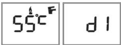
fig. 3
1.3 Lighting and shutdown
Burner not electrically powered

fig. 4 - Burner not electrically powered

The frost protection system does not work when the power and/or gas to the unit are turned off. To avoid damage caused by freezing during long shutdowns in winter, it is advisable to drain all water from the boiler, the DHW circuit and the heating system water; or drain just the DHW circuit and add a suitable antifreeze to the heating system, as prescribed in .
Burner ignition
Switch on the power to the burner.
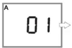


- For the next 180 seconds the display will show 0/FH which identifies the heating system air venting cycle.
- During the first 10 seconds the display also shows the software version of the cards (A = Display card software version / B = Controller software version).
- When the message FH disappears, the burner is ready to work automatically whenever there is a room thermostat demand.
Burner shutdown
Press the on/off button (detail 8 - fig.1) for 5 seconds.

When the device is turned off, the PCB is still powered. Domestic hot water and heating are disabled. The frost protection system remains activated. To switch the device on again, press the on/off button (detail 8 - fig.1) for 5 seconds.
The device will be immediately ready to work whenever domestic hot water is drawn or in case of a heating demand (generated by the Room Thermostat or Remote Timer control).
1.4 Adjustments
User menu
To access the user settings menu, press the Info button (detail 11 - fig. 1).
7 parameters and information indicated by the letter "u" are available.
Table 1
| Parameters User settings Range Default | |||
| u01 Heating adjustment temperature 30-80°C 80°C | |||
| u02 DHW adjustment temperature 10-65°C 65°C | |||
| u03 Summer/Winter selection 0 = Summer | 1 = Winter | 1 = Winter | |
| u04 Economy/Comfort selection 0 = Economy | 1 = Comfort | 0 = Economy | |
| u05 Burner max. power 1=Min, 5=Max 3 | |||
| u06 | Burner operation methodology | 0=request contact, 1, 2 | 0=request contact |
| u07 | Burner power (Step) and Flame status | 0-6 | - |
By pressing the Info button it is possible to scroll the list of user settings, only in ascending order, until exiting the menu.
Heating temperature adjustment
Press the Info button (detail 11 - fig. 1) until displaying the parameter u01 of the user settings menu.
Press Enter (detail 8 - fig. 1): the actual value of the parameter u01 is displayed.
Use the buttons (details 9 and 10 - fig. 1) to adjust the temperature from a min. of 30°C to a max. of 80°C.
Press Enter (detail 8 - fig. 1) to confirm the setting.
Then press the Info button (detail 11 - fig. 1) until exiting the menu.
DHW temperature adjustment
Press the Info button (detail 11 - fig. 1) until displaying the parameter u02 of the user settings menu.
Press Enter (detail 8 - fig. 1): the actual value of the parameter u02 is displayed.
Use the buttons (details 9 and 10 - fig. 1) to adjust the temperature from a min. of 10°C to a max. of 65°C.
Press Enter (detail 8 - fig. 1) to confirm the setting.
Then press the Info button (detail 11 - fig. 1) until exiting the menu.
Summer/Winter Switchover
Press the Info button (detail 11 - fig. 1) until displaying the parameter u03 of the user settings menu.
Press Enter (detail 8 - fig. 1): the actual value of the parameter u03 is displayed.
Use the buttons (details 9 and 10 - fig. 1) to set Summer mode (0) or Winter mode (1).
Press Enter (detail 8 - fig. 1) to confirm the setting.
Then press the Info button (detail 11 - fig. 1) until exiting the menu.
ECO/COMFORT selection
Heating/hot water tank temperature maintaining (Comfort) can be excluded by the user.
If excluded (Economy), domestic hot water will not be delivered.
Press the Info button (detail 11 - fig. 1) until displaying the parameter u04 of the user settings menu.
Press Enter (detail 8 - fig. 1): the actual value of the parameter u04 is displayed.
Use the buttons (details 9 and 10 - fig. 1) to set Economy (0) or Comfort (1) mode.
Press Enter (detail 8 - fig. 1) to confirm the setting.
Then press the Info button (detail 11 - fig. 1) to exit the menu.
Burner Max. Power
Press the Info button (detail 11 - fig. 1) until displaying the parameter u05 of the user settings menu.
Press Enter (detail 8 - fig. 1): the actual max power step is displayed.
Use the buttons (details 9 and 10 - fig. 1) to vary the max power: from 1 (min Step) to 5 (max Step).
Table 2 Burner max. power
| Parameter value SUN P7N | Power - kW | SUN P12N Power - kW |
| 1 14 30 | ||
| 2 20 36 | ||
| 3 25 41 | ||
| 4 30 48 | ||
| 5 34 55 |
Press Enter (detail 8 - fig. 1) to confirm the setting.
Then press the Info button (detail 11 - fig. 1) to exit the menu
Burner operation methodology
Press the Info button (detail 11 - fig. 1) until displaying the parameter u06 of the user settings menu.
Press Enter (detail 8 - fig. 1): the actual value of the parameter u06 is displayed.
Use the buttons (details 9 and 10 - fig. 1) to vary the operation methodology:
- u06=0 (default): Burner activation with request contact (230Vac) or with Room Thermostat contact (voltage-free). (Remote Control request by-passed).
• u06=1: Burner activation from Remote Control or with request contact (230Vac).
• u06=2: Burner activation from Remote Control and with request contact (230Vac).
Press Enter (detail 8 - fig. 1) to confirm the setting.
Then press the Info button (detail 11 - fig. 1) to exit the menu.
Actual burner power (Step) and Flame status
Press the Info button (detail 11 - fig. 1) until displaying the information u07 of the user settings menu.
Press Enter (detail 8 - fig. 1): the actual burner power (Step) and Flame status are displayed.
- 1 = Minimum Power
- 5 = Maximum power
- 0/FH = During Pre-ventilation/Post-ventilation
• 6 = During Post-ventilation2
Press Enter (detail 8 - fig. 1) to return to the list of parameters.
Then press the Info button (detail 11 - fig. 1) to exit the menu.
Room temperature adjustment (with optional room thermostat)
Using the room thermostat, set the temperature required in the rooms. If the room thermostat is not installed, the boiler will keep the system at the set system delivery setpoint temperature.
Room temperature adjustment (with optional remote timer control)
Using the remote timer control, set the required temperature in the rooms. The burner will adjust the system water according to the required room temperature. For operation with remote timer control, refer to the relevant instruction manual.
Adjustments from Remote Timer Control

If the Remote Timer Control (optional) is connected to the burner, the parameter "u06" must be modified (see *** 'Burner operation methodology' on page 8 ***); the previously described adjustments are managed as described in table 3.
Table 3
| Heating temperature adjustment | Adjustment can be made from the Remote Timer Control menu and the burner control panel. |
| DHW temperature adjustment | Adjustment can be made from the Remote Timer Control menu and the burner control panel. |
| Summer/Winter Switchover | Summer mode has priority over a possible Remote Timer Control heating demand. |
| Eco/Comfort selection Selection can only be made from the burner control panel | |
| Burner shutdown (off) Off mode can only be done from Remote Timer Control. | |
Parameters menu
The card Service Menu is accessed by pressing the Info button (detail 11 - fig. 1) for 10 seconds. Press the Up/Down buttons to select "tS", "In", "Hi" or "rE". "tS" means Transparent Parameters Menu, "In" means Information Menu, "Hi" means History Menu, "rE" means History Menu Reset. After selecting the menu, press the Info button to access it.
“ts” - Transparent parameters menu
Table 4
| Remote Control | Card | Transparent Parameters | Range | Default/SUN P7N | SUN P12N |
| 01 t01 Pellet loading function | 0=Disabled1=Enabled | 0=Disabled 0=Disabled | |||
| 02 t02 Delivery probe | 0=Disabled1=Enabled | 1=Enabled 1=Enabled | |||
| 03 t03 Fan setpoint in Lighting 0-200 Pa 51 Pa 51 Pa | |||||
| 04 t04 Auger activation time in Lighting | 0-100(1=4 seconds) | 8 (32 seconds) 8 (32 seconds) | |||
| 05 | t05 | Adjustment calculation timer (only with t18=1 and t18=2) | 0-100 seconds | 5 seconds | 5 seconds |
| 06 | t06 | Ramp function timer | 0-255 seconds | 150 seconds | 150 seconds |
| 07 | t07 | Auger operation period (activation time + deactivation) | 0-50 seconds | 15 seconds | 12 seconds |
| 08 t08 Fan setpoint at Power 1 | 0-200 Pa 51 Pa 51 Pa | ||||
| 09 t09 Auger activation time at Power 1 | 0-100(100=10 seconds) | 28 (2.8 seconds) | 38 (3.8 seconds) | ||
| 10 t10 Fan setpoint at Power 2 | 0-200 Pa 74 Pa 70 Pa | ||||
| 11 | t11 | Auger activation time at Power 2 | 0-100(100=10 seconds) | 38 (3.8 seconds) | 40 (4.0 seconds) |
| 12 | t12 | Fan setpoint at Power 3 | 0-200 Pa | 120 Pa | 100 Pa |
| 13 t13 Auger activation time at Power 3 | 0-100(100=10 seconds) | 46 (4.6 seconds) | 45 (4.5 seconds) | ||
| 14 | t14 | Fan setpoint at Power 4 | 0-200 Pa | 150 Pa | 120 Pa |
| 15 t15 Auger activation time at Power 4 | 0-100(100=10 seconds) | 53 (5.3 seconds) | 60 (6.0 seconds) | ||
| 16 | t16 | Fan setpoint at Power 5 | 0-200 Pa | 170 Pa | 155 Pa |
| 17 t17 Auger activation time at Power 5 | 0-100(100=10 seconds) | 56 (5.6 seconds) | 65 (6.5 seconds) | ||
| 18 t18 Burner operation selection (only with t02=1) | 0=On/Off1=Modulating2=Modulating 2 | 0=On/Off | 0=On/Off | ||
| 19 t19 Post-ventilation 2 Time | 0-255(100=10 seconds) | 200 (20 seconds) | 200 (20 seconds) | ||
| 20 | t20 | Photoresistance voltage (display only) | 0-50 (50=5Vdc) | -- | -- |
| 21 t21 Auger activation function in Lighting | 0=Continuous1=Cycle On/Off | 0=Continuous | 0=Continuous | ||
| 22 | t22 | Photoresistance voltage threshold | 0-100 (100=1Vdc) | 50 | 50 |
| 23 t23 Burner type selection | 1=P7/ECO 3.4 P2=P123=ECO 5.5 P | 1=P7/ECO 3.4 P | 2=P12 | ||
| 24 | P24 | System water pressure protection selection | 0=No Pressure switch,1=Pressure switch | 0=No Pressure switch | 0=No Pressure switch |
| 25 | P25 | Boiler type selection | 1=Heating only2=Storage with probe3=Storage with probe4=Instantaneous | 1 | 1 |
| 26 | P26 | Heating pump activation temperature (P25=1) | 0-80°C | 30°C | 30°C |
| Heating pump activation temperature (P25=2) | 0-80°C | 30°C | 30°C | ||
| Heating pump activation temperature (P25=3) | 0-80°C | 30°C | 30°C | ||
| Heating pump activation temperature (P25=4) | 0-80°C | 30°C | 30°C | ||
| 27 | P27 | Post-circulationHeating pump | 0-20 minutes | 6 minutes | 6 minutes |
| 28 | P28 | Heating standby time | 0-10 minutes | 2 minutes | 2 minutes |
| 29 P29 Pump operation | 0=Post-Circulation 1=Continuous | 0=Post-Circulation 0= | Post-Circulation | ||
| 30 P30 | Pump deactivation temperature during Post-Circulation (P25=1) 0-100°C 35°C 35°C | ||||
| Pump deactivation temperature during Post-Circulation (P25=2) 0-100°C 35°C 35°C | |||||
| Pump deactivation temperature during Post-Circulation (P25=3) 0-100°C 35°C 35°C | |||||
| Pump deactivation temperature during Post-Circulation (P25=4) 0-100°C 35°C 35°C | |||||
| 31 P31 Heating user max. set point 31-90°C 80°C 80°C | |||||
| 32 P32 | No function (P25=1) -- -- -- | ||||
| DHW pump activation temperature (P25=2) 0-80°C 40°C 40°C | |||||
| DHW pump activation temperature (P25=3) 0-80°C 40°C 40°C | |||||
| DHW pump activation temperature (P25=4) 0-80°C 40°C 40°C | |||||
| 33 P33 DHW pump Post-Circulation 0-20 minutes 4 minutes | 4 minutes | ||||
| 34 | P34 | DHW standby time | 0-20 minutes | 4 minutes | 4 minutes |
| 35 P35 | DHW user max. setpoint (P25=1) | -- -- -- | |||
| DHW user max. setpoint (P25=2) | 55-65°C 65°C 65°C | ||||
| DHW user max. setpoint (P25=3) | 55-65°C 65°C 65°C | ||||
| DHW user max. setpoint (P25=4) | -- -- -- | ||||
| 36 P36 | No function (P25=1) -- -- -- | ||||
| Hot water tank activation hysteresis temperature (P25=2) | 0-20°C | 4°C | 4°C | ||
| Hot water tank activation hysteresis temperature (P25=3) | 0-20°C | 4°C | 4°C | ||
| No function (P25=4) -- -- -- | |||||
| 37 P37 | No function (P25=1) -- | -- | |||
| Hot water tank preparation delivery temperature (P25=2) | 70-85°C 80°C 80°C | ||||
| Hot water tank preparation delivery temperature (P25=3) | 70-85°C 80°C 80°C | ||||
| DHW mode delivery adjustment temperature (P25=4) | 50-75°C 55°C 55°C | ||||
| 38 P38 | Boiler shell warm-up activation temperature (P25=1) | 0-80°C | 0°C | 0°C | |
| Boiler shell warm-up activation temperature (P25=2) | 0-80°C | 0°C | 0°C | ||
| Boiler shell warm-up activation temperature (P25=3) | 0-80°C | 0°C | 0°C | ||
| Comfort activation temperature (P25=4) | 0-80°C 55°C 55°C | ||||
| 39 P39 | Boiler shell warm-up deactivation hysteresis (P25=1) | 0-20°C | 5°C | 5°C | |
| Boiler shell warm-up deactivation hysteresis (P25=2) | 0-20°C | 5°C | 5°C | ||
| Boiler shell warm-up deactivation hysteresis (P25=3) | 0-20°C | 5°C | 5°C | ||
| Comfort deactivation hysteresis (P25=4) | 0-20°C 20°C 20°C | ||||
| 40 | P40 | Safety and heating sensor selection | 0-2 | 0 | 0 |
| 41 | P41 | Variable output relay operation (P25=1) | 0-4 | 0 | 0 |
| 42 P42 | No function (P25=1) -- -- -- | ||||
| Legionella protection (P25=2) | 0-7 | 0 | 0 | ||
| Legionella protection (P25=3) | 0-7 | 0 | 0 | ||
| No function (P25=4) -- -- -- | |||||
Press the Up/Down buttons to scroll the list of parameters in ascending or descending order. To change the value of a parameter just press Enter at the parameter and then modify it with the Up/Down buttons: the change will be saved automatically.
To return to the list of parameters just press Enter.
To return to the Service Menu just press the Info button. To exit the card Service Menu press the Info button for 10 seconds or exiting will be automatic after 15 minutes
"In" - Information Menu
The card can display the following information:
| Contents Description Range | ||
| t01 NTC | Heating sensor (°C) between 05 and 125°C | |
| t02 NTC | Safety sensor (°C) between 05 and 125°C | |
| t03 | Hot water tank NTC sensor (°C) (only with parameter P25=2, storage boiler) | between 05 and 125°C |
| Flow switch status (On/Off) (only with parameter P25=4, instantaneous boiler) On/Off | ||
| P04 Actual system water pressure (bar/10) 00-99 bar/10 | ||
| P05 Burner power (Step) and Flame status 0-6 | ||
| P06 Actual air pressure (Pa) 00-255 Pa | ||
| P07 Actual air pressure setpoint (Pa) 00-255 Pa (00 with burner off) | ||
| P08 Actual air pressure Switch Off setpoint (Pa) 00-255 Pa (00 with burner off) | ||
| C09 Auger (On/Off) On/Off | ||
| F10 Photoresistance voltage | 0-50 | |
Press the Up/Down buttons to scroll the list of information in ascending or descending order. To display the value just press Enter at the parameter. In case of damaged sensor, the card displays hyphens.
To return to the list of parameters just press Enter.
To return to the Service Menu just press the Info button. To exit the card Service Menu press the Info button for 10 seconds or exiting will be automatic after 15 minutes.
"Hi" - History Menu
The microprocessor can memorize the total hours with card powered (Ht), the last 10 faults and the hours of burner operation (Hb).
The History datum item H1 represents the most recent fault that occurred, whereas the History datum item H10 represents the least recent. The codes of the faults saved are also displayed in the corresponding menu of the Opentherm remote control.
Press the Up/Down buttons to scroll the list of faults. To display the value just press Enter at the parameter.
To return to the list of faults just press Enter.
| Ht | Total hours with card powered |
| H1 | Fault code |
| H2 | Fault code |
| H3 | Fault code |
| H4 | Fault code |
| H5 | Fault code |
| H6 | Fault code |
| H7 | Fault code |
| H8 | Fault code |
| H9 | Fault code |
| H10 | Fault code |
| Hb | Hours of burner operation |
To return to the Service Menu just press the Info button. To exit the card Service Menu press the Info button for 10 seconds or exiting will be automatic after 15 minutes.
"rE" - History Reset
By pressing Enter for 3 seconds it will be possible to delete all the faults stored in the History Menu: the card will automatically exit the Service Menu, in order to confirm the operation.
To exit the card Service Menu press the Info button for 10 seconds or exiting will be automatic after 15 minutes.
1.5 Operating instructions
Once the burner is installed and correctly adjusted, its operation is fully automatic without requiring any control by the user. In case of anomalies or no fuel, the burner stops and shuts down. To avoid irregular burner operation it is advisable to top-up the fuel before it finishes.
Make sure the room where the burner is installed is free of flammable materials or objects, corrosive gases and volatile substances, and that it is not dusty. In fact, dust drawn by the fan sticks to the blades and reduces the air flow or obstructs the flame stability disk thereby affecting its efficiency.

Do not allow unskilled persons or children to tamper with the burner.
1.6 Cleaning the burner grille
Before cleaning or any maintenance work, disconnect the power supply to the burner.
To avoid malfunctions and burner shutdowns, it is necessary to clean the combustion head grille.
Cleaning must be carried out at least once a week and in any case whenever the grille is obstructed by combustion residues.
To clean, wait for the burner to cool down completely.
Lift the grille, remove the nozzle and suck the ash. If necessary, free the slots by removing combustion residues using a metal brush.
Suck the ash present inside and outside the nozzle.
Refit the grille, making sure the pin is correctly positioned in the locking hole.

natural_image
Technical line drawing of two mechanical components with directional arrows indicating movement or assembly (no text or symbols present)fig. 5- Cleaning the grille
2. Installation
2.1 General Instructions
This unit must only be used for its intended purpose.
This unit can be used with heat generators for solid fuels, compatibly with its characteristics, performance and heating capacity. Any other use is deemed improper and therefore hazardous. Opening or tampering with the unit's components is not allowed (except for the parts requiring servicing); do not modify the unit to alter its performance or intended use.
If the burner is completed with optionals, kits or accessories, only use original products.

BURNER INSTALLATION AND SETTING MUST ONLY BE CARRIED OUT BY QUALIFIED AND SPECIALISED PERSONNEL, IN COMPLIANCE WITH ALL THE INSTRUCTIONS GIVEN IN THIS TECHNICAL MANUAL, THE CURRENT PROVISIONS OF LAW, THE PRESCRIPTIONS OF NATIONAL AND LOCAL STANDARDS, AND THE RULES OF PROPER WORKMANSHIP.
2.2 Installation in boiler
Place of installation
The room where the boiler and burner are installed must have openings to the outside as required by the current regulations. If there are several burners or exhausters that can work together in the same room, the ventilation openings must be sized for simultaneous operation of all the units.
The place of installation must be free of flammable materials or objects, corrosive gases, dusts or volatile substances which, drawn by the fan, can obstruct the pipes inside the burner or the combustion head. The room must be dry and not exposed to rain, snow or frost.
Fix the burner to the door. Make the electrical connections as shown in cap. 4.4 "Wiring diagram" (wiring diagram). If the burner is installed in a boiler Caldaia, use the special conversion kit. Insert the temperature probe (contained in the kit) in the sheathing on the cast-iron boiler shell and make the respective electrical connections.

THE BURNER IS DESIGNED TO WORK ON HEAT GENERATORS WITH COMBUSTION CHAMBER IN NEGATIVE PRESSURE.
THE PELLET HOPPER MUST BE POSITIONED SO THAT THE AUGER/BURNER FLEXIBLE CONNECTION TUBE IS NOT TWISTED AND/OR BENT.
Burner assembly instructions
For burner assembly (fig. 6), it is advisable to separate it as indicated in fig. 7.

fig. 7
Secure the nozzle "E" with the screws "F" (fig. 8).
Secure the burner body "G with the nut "H".
Secure the pellet duct "L", interposing the gasket "M", to the burner nozzle (fig. 9).

fig. 8
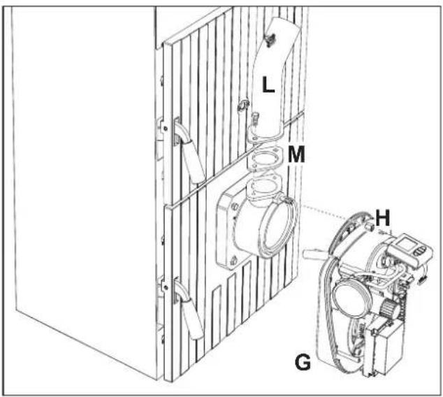
fig. 9
Place the pellet hopper "N" on the side of the boiler (fig. 10).
Insert the motorized feed tube "P" in the pellet hopper "N" and make the auger-burner connection so that the hose "R" (fig. 10) is not twisted or bent and that it does not come into contact with hot parts that could damage it. Make sure to respect the value indicated in the fig. 10 and the position as indicated in fig. 11.

fig. 10
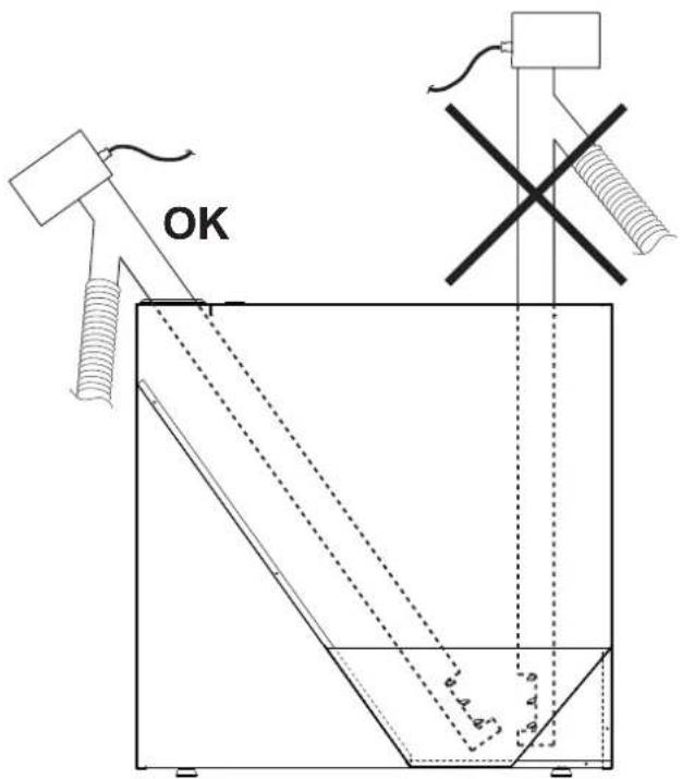
fig. 11- Pellet feed tube position
Electrical connections (fig. 12)
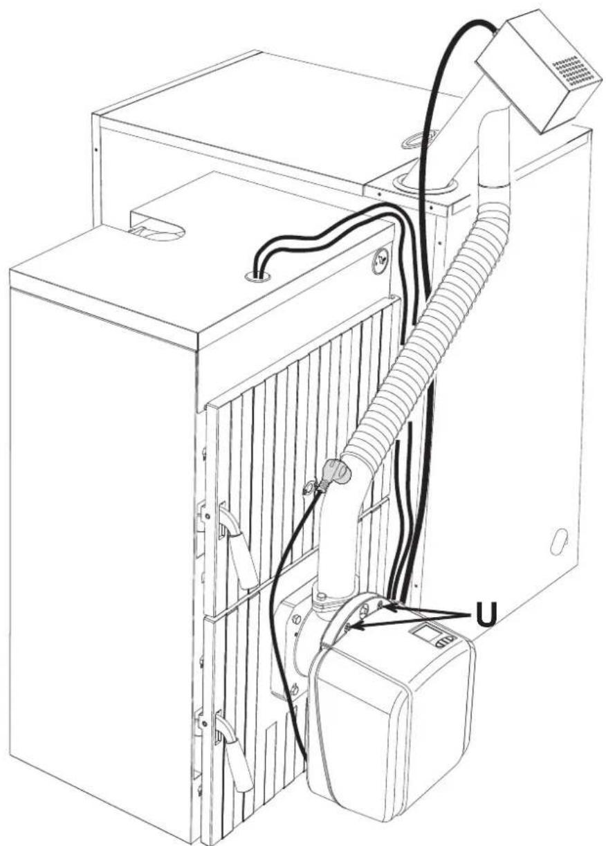
Run the cables through the slots behind the burner (fig. 12)
Connect the cable of the safety thermostat "49" to the terminals 20 and 21 and the cable of the temperature sensor cable "34" to the terminals 18 and 19. Connect the cable "B" of the motor auger "P" to the terminals 6, 7 and 8.
Insert the connector "V" on the "pellet safety thermostat" "T - 218" and connect the cable to the terminals 4 and 5. Make sure the cable does not touch the burner nozzle.
Secure the casing "P" to the burner body with the screws "U" fig. 13.

Position all the cables so that they are not in direct contact with the hot parts of the boiler and burner.

fig. 12
natural_image
Technical line drawing of an industrial machine with hoses and control panel (no text or symbols)fig. 13
Adjust the burner as described in the relevant instruction manual and, in particular, set the parameter u05 on the burner controller as indicated in the table.
| Burner model SUN P7N SUN P12N | ||||||
| Boiler model Caldaia | SUNPELLET 3 | SUNPELLET 4 | SUNPELLET 5 | SUNPELLET 6 | SUNPELLET 7 | |
| Nominal heating capacity kW | 24.9 33 | 4 41 48 55 | ||||
| Nominal heat output kW 22 30 | 36 42 | 48 | ||||
| Parameter | u05 | 2 | 5 | 3 | 4 | 5 |
2.3 Electrical connections
The burner is equipped with a multi-pole terminal block for the electrical connections; refer to the wiring diagram in section "4 Technical data and characteristics" for the connections. The connections to be made by the installer are all those indicated by the dashed lines in the wiring diagram (see fig. 23).
The length of the connection cables must allow the burner and, if necessary, the boiler door to be opened. If the burner power cable is damaged, it must only be replaced by qualified personnel.
The burner must be connected to a single-phase 230 Volt-50 Hz electric line.

Have the efficiency and suitability of the earthing system checked by professionally qualified personnel; the Manufacturer declines any liability for damage caused by failure to earth the system. Also make sure the electrical system is adequate for the maximum power absorbed by the unit, as specified on the boiler data plate.
Make sure to respect the polarities (LINE: brown wire / NEUTRAL: blue wire / GROUND: yellow-green wire) in the connections to the electric line.
2.4 Fuel supply
General Instructions
The burner must be fed with the type of fuel for which it is arranged, as specified on the unit's dataplate and in the technical data table on of this manual.
The user is advised to use good quality pellets, since low quality pellets result in low heat outputs, high ash content with subsequent need of frequent cleaning, possible early wear of burner parts exposed to the fire, clogging of the auger and burner due to excess loose sawdust, and operation shutdowns due to sedimentation of unburnt materials inside the burner.
To identify quality pellets it is advisable to proceed as follows:
- They must be cylinders of constant diameter and have a smooth and bright surface.
- Check that the labels give the details of the quality certifications
- Check that the packs are intact so that the pellets do not absorb humidity.
Pellet loading
Pellet loading can be activated within 40 minutes after switching on the power to the burner.
Within this time, the system makes available three 5-minute attempts, during which only the auger is activated.
The burner cannot be lit during pellet loading.
Sequence:
- Switch on the power to the burner.
- Wait for the pre-ventilation stage to end.
- Remove burner ignition request.
- Press and hold down the button (detail 10 - fig. 1) for 3 seconds.
- “R” (detail 5 - fig. 1) flashes, identifying the imminent start of the PELLET loading procedure.
- After two seconds, the auger will be electrically powered and continuously for a maximum time of 5 minutes.
- The PELLET loading procedure can be terminated at any time by pressing and holding down the button ▼ (detail 10 - fig. 1) for 3 seconds.
- If the maximum pellet loading time (5 minutes) is reached, the power to the auger is switched off.
- Press and hold down the button (detail 10 - fig. 1) for 3 seconds.
- The message "R" will disappear and the display returns to normal operation.
- If the first attempt was not sufficient, repeat the previous sequence from point 4 to start the second attempt
- If the second attempt was not sufficient, repeat the previous sequence from point 4 to start the third and last attempt
- In order to do another 3 attempts, switch the power to the unit off and then on again
- After the loading of pellets, reinstate the burner ignition request.
2.5 Connection to an external hot water tank
Connection with circulating pump
The unit's electronic card is arranged for managing an external DHW storage tank. Carry out the plumbing connections according to the diagram fig. 14 (pumps and non-return valves must be supplied separately). Carry out the electrical connections as shown in the wiring diagram (see fig. 23). A FERROLI probe must be used. At the next lighting, the boiler control system detects the hot water tank probe and automatically configures the DHW function, activating the display and relevant controls.

flowchart
graph TD
    A["Input"] --> B["Reactor Unit"]
    B --> C["10"]
    B --> D["11"]
    B --> E["32"]
    E --> F["130"]
    F --> G["42"]
    G --> H["Output 8"]
    G --> I["Output 9"]
fig. 14- Diagram of connection with circulating pump
Connection with diverter valve
The unit's electronic card is arranged for managing an external DHW storage tank. Carry out the plumbing connections according to the diagram fig. 15 (the 3-way valve must be supplied separately). Carry out the electrical connections as shown in the wiring diagram (see fig. 23). A FERROLI probe must be used.
Change parameter P25 of the "Transparent Parameters Menu" to 3.
At the next lighting, the boiler control system detects the hot water tank probe and automatically configures the DHW function, activating the display and relevant controls.

flowchart
graph TD
    A["Feed Inlet"] --> B["Reactor Unit"]
    B --> C["10 Valve"]
    B --> D["32 Valve"]
    B --> E["95 Valve"]
    C --> F["Reactor Column"]
    D --> G["Reactor Column"]
    E --> H["Reactor Column"]
    F --> I["Heat Exchanger"]
    G --> J["Heat Exchanger"]
    H --> K["Heat Exchanger"]
    I --> L["Output 8"]
    J --> M["Output 9"]
    K --> N["Output 42"]
fig. 15- Diagram of connection with diverter valve
- Legend fig. 14 and fig. 15
8 Domestic hot water outlet
9 Cold water inlet
10 System flow
11 System return
32 Heating circulating pump
42 DHW temperature sensor
130 Hot water tank circulating pump
95 3-way valve - 2 wires with spring return (not supplied)
- Powered (230 Vac) = Heating position
- Not powered = DHW position
3. Service and maintenance
All adjustment, commissioning and maintenance operations must be carried out by Qualified Personnel in compliance with current regulations. The personnel of our sales organization and the Local After-Sales Technical Service are at your disposal for any further information.
FERROLI declines any liability for damage and/or injury caused by unqualified and unauthorized persons tampering with the unit.
3.1 Commissioning
Checks to be made at first lighting, and after all maintenance operations involving disconnection of the systems or any operation on safety devices or parts of the burner:
Before lighting the burner
• Make sure the burner is correctly fixed in the boiler with the preliminary settings indicated above.
- Make sure the boiler and system are filled with water or diathermic oil, the plumbing circuit valves are open and that the flue is free and correctly sized.
- Check closing of the boiler door, so that the flame is only generated inside the combustion chamber.
- Check the correct positioning of the auger and the burner connection flexible tube.
- Fill the hopper with pellets.
- Check the correct positioning and connection of the temperature probe.

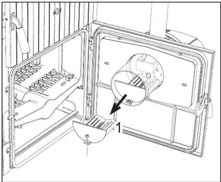
Make sure the grille (detail 1 fig. 16) is clean.
natural_image
Technical line drawing of a mechanical assembly with internal components and a labeled component (no text or symbols present)- Switch on the power, operating the main switch ahead of the burner.
• To fill the auger with pellets, see sec. 2.4. - close the thermostat line (boiler/room).
Burner setting
- Connect a combustion analyser to the boiler outlet and leave the burner working at max. for 30 minutes; in the meantime check the fume extraction duct.
- MAKE SURE THE COMBUSTION CHAMBER IS IN NEGATIVE PRESSURE
- Check the combustion at max. burner power (adjusted according to boiler rated output).
- Combustion parameters:
- O_2 between 5 % and 9 %
• CO between 150 and 1000 ppm
NOTE
The CO value is affected by the quality of the pellets, the amount of dirt in the combustion head, and boiler draft. If necessary, for burner calibration, vary the fan set point by modifying the relevant parameter (see par. "Parameters menu" on page 9 and Table 2, "Burner max. power," on page 7).
- After checking combustion at maximum power, also check the other burner steps, repeating the procedure described above and reducing the value of the parameter u05 to 1 (see par. "Parameters menu" on page 9 and Table 2, "Burner max. power," on page 7).
- To operate the burner in Modulating mode, it is necessary to modify the parameter t18 (see par. Parameters Menu)
- Restore the burner maximum power parameter u05 to the desired value (adjusted according to boiler nominal power)
3.2 Maintenance
Checks and controls

Periodically check the cleanness of the burner parts which will tend to get dirty depending on the quality of the pellets or due to incorrect burner adjustment.

Periodically check the pellet hopper and remove dust from the bottom. An excessive amount of dust can affect the proper supply of fuel to the burner.
The burner requires periodical maintenance which must be performed by qualified personnel at least once a year.
The basic operations to carry out are:
- check and cleaning of the internal parts of the burner and boiler as indicated in the following sections;
• complete combustion analysis (after at least 10 minutes' operation) and check of correct settings;
Opening the casing and removing the burner

Before carrying out any checking or cleaning inside the burner, disconnect the power to the burner by means of the main system switch.
To open
Undo the screws (A) and remove the casing (B). The internal components, motor, damper, etc., are directly accessible.

fig. 17- Casing opening
To disassemble the burner
After removing the casing, unscrew the nut (C) and disconnect the body, undo the fixing screws (D) and remove the nozzle (E).
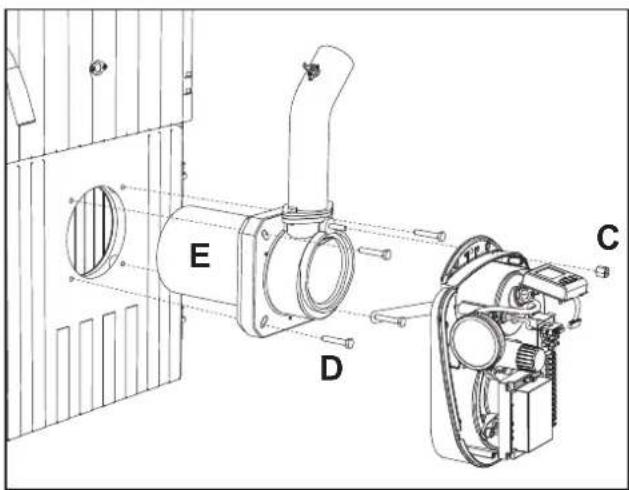
fig. 18- Burner disassembly
Checks on parts and components
Fan
Make sure no dust has accumulated inside the fan and on the blades: it reduces the air flow, thus causing pollutant combustion.
Combustion head
Make sure all parts of the combustion head are intact, not warped by the high temperature, free of impurities coming from the room, and correctly positioned.
Photoresistance
Remove any dust on the glass. The photoresistance is press-on; to remove, pull it outwards.
3.3 Troubleshooting
The burner is equipped with an advanced self-diagnosis system. In case of a burner fault, the display (detail 4 - fig. 1) flashes indicating the fault code.
There are faults the cause permanent shutdowns (marked with the letter "A"): to reinstate operation, press the "Reset" button (detail 8 - fig. 1) for 1 second; if the burner fails to restart, it is necessary to firstly eliminate the fault.
Other faults cause temporary shutdowns (marked with the letter "F") which are automatically reset as soon as the value returns within the burner's normal operating range.
Table 5 - List of faults
| Fault Fault Cause Cure | |||
| A01 | No ignition shutdown | Pellet container empty Fill the container with pellets | |
| Auger cable broken or disconnected Restore the connection | |||
| Faulty igniter resistance Replace and empty the head of pellets | |||
| Combustion head dirty Empty and clean it | |||
| Pellet feed duct obstructed | Free it, make sure the combustion head is not clogged and empty it if necessary | ||
| F02 | Parasite flame elimination | The demand for heat has ended, but the burner detects flame | Wait for end of post-ventilation |
| Incorrect ignition parameters Check ignition parameters | |||
| A02 | Shutdown for parasite flame | Photoresistance short circuit Replace the photoresistance | |
| Extraneous light strikes the photoresistance Eliminate the light source | |||
| Incorrect ignition parameters Check ignition parameters | |||
| A03 | Wiring fault | Jumper of terminals 20-21 not connected | Check the wiring |
| A04 | Auger safety thermostat block | Boiler under pressure | Clean it and check correct minimum flue draft (10Pa) |
| Faulty safety thermostat | Replace it | ||
| Auger cable broken or disconnected Restore the connection | |||
| F05 | Incorrect pipe pressure adjustment | Pressure sensor connection tube squashed | Replace |
| Fan motor damaged | Replace | ||
| Fan dirty | Clean it | ||
| F06 | Pressure transducer fault (disconnected) | Wiring disconnected | Check the wiring or replace the sensor |
| F10 | Boiler shell probe fault (if enabled) | Sensor damaged | Check the wiring or replace the sensor |
| Wiring shorted | |||
| Wiring disconnected | |||
| F11 | DHW sensor fault | Sensor damaged | Check the wiring or replace the sensor |
| Wiring shorted | |||
| Wiring disconnected | |||
| F14 | Card parameter fault | Wrong card parameter setting | Check the card parameter and modify it if necessary |
| F34 | Supply voltage under 170V. | Electric mains trouble | Check the electrical system |
| F37 | Card parameter fault | Wrong card parameter setting | Check the card parameter and modify it if necessary |
| F42 | Card parameter fault | Wrong card parameter setting | Check the card parameter and modify it if necessary |
4. TECHNICAL DATA AND CHARACTERISTICS
4.1 Dimensions
Boiler dimensions
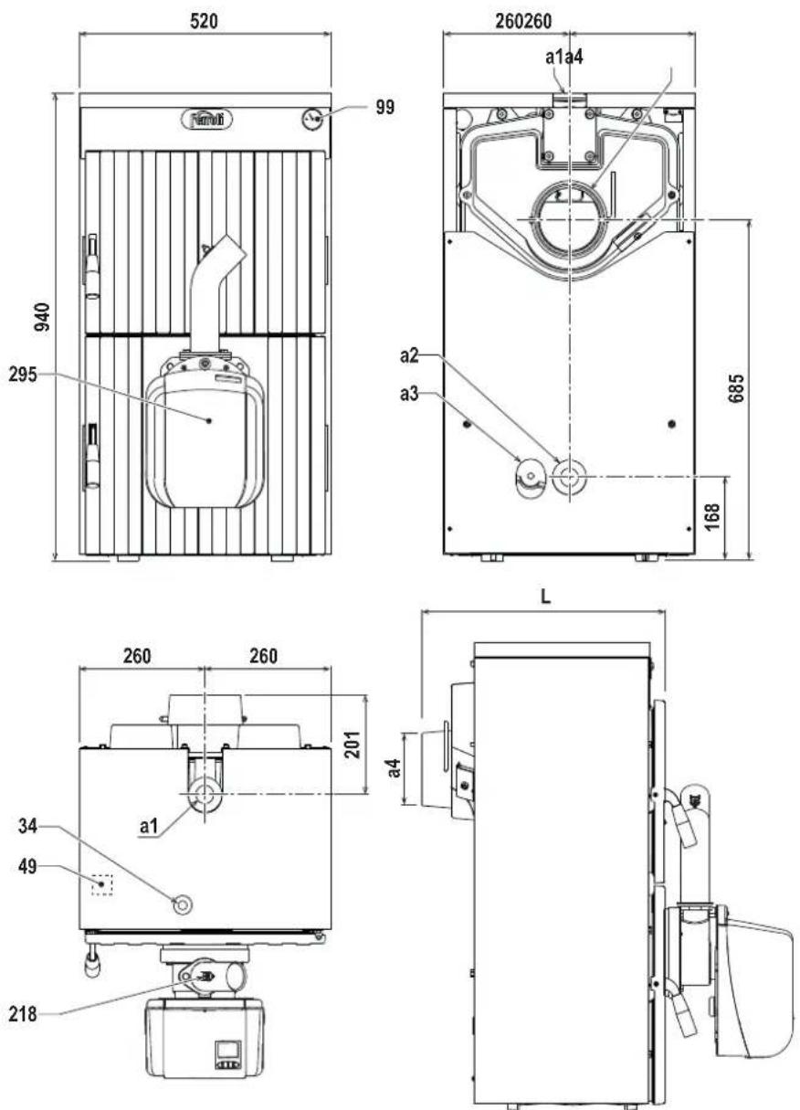
fig. 19- Boiler dimensions
| Model L a4 - ∅ | mm | |
| SUNPELLET 3 510 | 150 | |
| SUNPELLET 4 620 | 150 | |
| SUNPELLET 5 730 | 150 | |
| SUNPELLET 6 840 | 180 | |
| SUNPELLET 7 950 | 180 |
a1 System delivery - ∅ 1" 1/2
a2 System return - ∅ 1" 1/2
a3 System drain - ∅ 1/2"
a4 Flue
34 Heating temperature sensor
49 Boiler safety thermostat
99 Thermometer
218 Pellet safety thermostat
295 Burner
Burner dimensions


fig. 20 - Dimensional SUN P7N


fig. 21 - Dimensional SUN P12N
4.2 General view and main components

fig. 22
Legend
1 Pressure transducer
2 Controller
3 Burner body
4 Terminal block
5 User interface
6 Heating element
7 Photoresistance
8 Thermostat 85°
9 Burner loading tube
10 Motor
11 Fan
12 Nozzle
13 Grille
4.3 Technical data table
The column on the right gives the abbreviation used on the data plate.
| Data Unit | SUNPELLET 3 | SUNPELLET 4 | SUNPELLET 5 | SUNPELLET 6 | SUNPELLET 7 | ||
| Heat output kW 22 30 36 42 48 (P) | |||||||
| Efficiency % 88.48 88.66 88.7 89.02 89.3 | |||||||
| Max. working pressure | bar. | 4 | 4 | 4 | 4 | 4 | |
| Water content | L. 26 30 34 38 42 | ||||||
| Chamber volume | dm^3 | 48 68 88 | 108 | 128 | |||
| Recommended temperature setting | °C | >60 | >60 | >60 | >60 | >60 | |
| Boiler return min. temperature | °C 50 50 50 50 50 | ||||||
| Min. flue draught | Pa 23 25 28 30 32 | ||||||
| Efficiency class EN303-5 | 5 | 5 | 5 | 5 | 5 | ||
| Efficiency class EN303-5 | 5 | 5 | 5 | 5 | 5 | ||
| Empty weight | kg | 193 | 241 | 289 | 337 | 385 | |
ErP product fiche
MODEL: SUNPELLET 3 (0JCJ3UWA)
| Trademark: FERROLI | |
| Item Symbol Unit Value | |
| Energy efficiency class EEI A+ | |
| Rated heat output Pn kW 22 | |
| Energy efficiency index EEI 122 | |
| Seasonal space heating energy efficiency ηS %83 |
MODEL: SUNPELLET 4 (0JCJ4UWA)
| Trademark: FERROLI | |
| Item Symbol Unit Value | |
| Energy efficiency class EEI A+ | |
| Rated heat output Pn kW 30 | |
| Energy efficiency index EEI 122 | |
| Seasonal space heating energy efficiency | _S % 83 |
MODEL: SUNPELLET 5 (OJCJ5UWA)
| Trademark: FERROLI | |
| Item Symbol Unit Value | |
| Energy efficiency class EEI A+ | |
| Rated heat output Pn kW 36 | |
| Energy efficiency index EEI 122 | |
| Seasonal space heating energy efficiency ηS % 83 |
MODEL: SUNPELLET 6 (0JCJ6UWA)
| Trademark: FERROLI | |
| Item Symbol Unit Value | |
| Energy efficiency class EEI A+ | |
| Rated heat output Pn kW 42 | |
| Energy efficiency index EEI 122 | |
| Seasonal space heating energy efficiency ηS % 83 |
MODEL: SUNPELLET 7 (0JCJ7UWA)
| Trademark: FERROLI | |
| Item Symbol Unit Value | |
| Energy efficiency class EEI A+ | |
| Rated heat output Pn kW 48 | |
| Energy efficiency index EEI 122 | |
| Seasonal space heating energy efficiency | _S % 83 |
4.4 Wiring diagram

DO NOT CONNECT "LINE" OR "NEUTRAL" SIGNALS COMING FROM THE ELECTRICAL SYSTEM TO THE TERMINAL BLOCK.
ALL CONNECTIONS MUST BE MADE AS SHOWN IN THE WIRING DIAGRAM. EXTERNAL ELECTRICAL LOADS TO BE WIRED TO THE TERMINAL BLOCK MUST NOT EXCEED 100W FOR EACH SINGLE OUTPUT. FOR THE CONNECTION OF LOADS AND CONTACT "C" (230V), USE A DOUBLE INSULATION CABLE.

fig. 23 - Wiring diagram
N.B. Remove the jumper on contacts 9-10 before connecting the remote timer control or room thermostat.
Key - Wiring diagram fig. 23
A electrical power supply
B Motor auger
C Request contact
D Shutdown signal
E Burner reset
FR Photoresistance
16 Fan
32 Heating circulating pump (not supplied)
34 Heating temperature sensor
42 DHW temperature sensor (optional)
49 Boiler safety thermostat
72 Room thermostat (optional)
95 Diverter valve (optional)
- Powered (230 Vac) = Heating position
- Not powered = DHW position
114 Water pressure switch (not supplied)
130 Hot water tank circulating pump (not supplied)
139 Remote timer control (optional)
218 Pellet safety thermostat
239 Igniter
297 Air pressure transducer
Ferroli
FERROLI S.p.A.
Via Ritonda 78/a
37047 San Bonifacio - Verona - ITALY
www.ferroli.com
Made in Italy
- Operating instructions .... 4
- Installation....13
- Service and maintenance....19
- TECHNICAL DATA AND CHARACTERISTICS....23
- Operating instructions
- Introduction
- Control panel
- Indication during operation
- Heating
- Domestic hot water (DHW)
- Lighting and shutdown
- Burner ignition
- Burner shutdown
- Adjustments
- User menu
- Heating temperature adjustment
- DHW temperature adjustment
- Summer/Winter Switchover
- ECO/COMFORT selection
- Burner Max. Power
- Burner operation methodology
- Actual burner power (Step) and Flame status
- Room temperature adjustment (with optional room thermostat)
- Room temperature adjustment (with optional remote timer control)
- Adjustments from Remote Timer Control
- Parameters menu
- “ts” - Transparent parameters menu
- "In" - Information Menu
- "Hi" - History Menu
- "rE" - History Reset
- Operating instructions
- Do not allow unskilled persons or children to tamper with the burner.
- Cleaning the burner grille
- Installation
- General Instructions
- Installation in boiler
- Place of installation
- Burner assembly instructions
- Electrical connections (fig. 12)
- Electrical connections
- Fuel supply
- General Instructions
- Pellet loading
- Sequence:
- Connection to an external hot water tank
- Connection with circulating pump
- Connection with diverter valve
- - Legend fig. 14 and fig. 15
- Service and maintenance
- Commissioning
- Before lighting the burner
- Burner setting
- NOTE
- Maintenance
- Checks and controls
- Opening the casing and removing the burner
- To open
- To disassemble the burner
- Checks on parts and components
- Fan
- Combustion head
- Photoresistance
- Troubleshooting
- TECHNICAL DATA AND CHARACTERISTICS
- Dimensions
- Legend
- Technical data table
- ErP product fiche
- Wiring diagram
- N.B. Remove the jumper on contacts 9-10 before connecting the remote timer control or room thermostat.
- Key - Wiring diagram fig. 23
- Ferroli
Brand : FERROLI
Model : Sun Pellet
Category : Cooker