
VSX 15DR - Subwoofer TANNOY - Free user manual and instructions
Find the device manual for free VSX 15DR TANNOY in PDF.


| Product Type | Active Subwoofer |
| Driver Size | 15 inches |
| Amplifier Power | 800W RMS |
| Frequency Response | 30 Hz - 150 Hz |
| Maximum SPL | 130 dB |
| Enclosure Type | Bass Reflex |
| Inputs | XLR, Speakon |
| Outputs | XLR Thru |
| Dimensions (HxWxD) | 20.5 x 19.7 x 19.7 inches |
| Weight | 64 lbs |
| Power Supply | 100-240V AC, 50/60Hz |
| Protection Features | Overload, Thermal, Short Circuit |
| Cabinet Construction | Plywood with Duriflex coating |
| Grille | Perforated steel with acoustic foam |
| Mounting Options | Floor standing, optional pole mount |
| Maintenance | Clean with dry cloth; avoid moisture |
| Safety | Do not remove cover; risk of electric shock |
| Spare Parts | Available via Tannoy authorized dealers |
| Repairability | Service by qualified personnel only |
| General Information | Professional grade subwoofer for live sound and installation |
Frequently Asked Questions - VSX 15DR TANNOY
User questions about VSX 15DR TANNOY
0 question about this device. Answer the ones you know or ask your own.
Ask a new question about this device
Download the instructions for your Subwoofer in PDF format for free! Find your manual VSX 15DR - TANNOY and take your electronic device back in hand. On this page are published all the documents necessary for the use of your device. VSX 15DR by TANNOY.
USER MANUAL VSX 15DR TANNOY
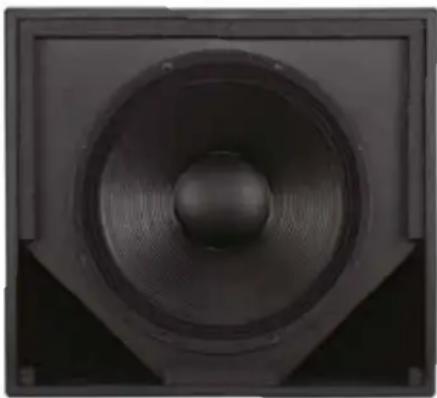
High-performance subwoofers
natural_image
Close-up of a black speaker cone with concentric circular design (no text or symbols visible)
natural_image
Dark rectangular object with a vertical slot, possibly a lens or aperture (no text or symbols visible)Important Safety Instructions
The lightning flash with arrowhead symbol within an equilateral triangle, is intended to alert the user to the presence of uninsulated "dangerous voltage" within the product's enclosure that may be of sufficient magnitude to constitute a risk of electric shock to persons.
- Read these instructions.
- Keep these instructions.
- Heed all warnings.
- Follow all instructions.
- Do not use this apparatus near water.
- Clean only with a dry cloth.
- Do not block any ventilation openings. Install in accordance with the manufacturer's instructions.
- Do not install near any heat sources such as radiators, heat registers, stoves, or other apparatus (including amplifiers that produce heat).
- Only use attachments / accessories specified by the manufacturer.
- Use only with a cart, stand, tripod, bracket, or table specified by the manufacturer, or sold with the apparatus. When a cart is used, use caution when moving the cart / apparatus combination to avoid injury from tip-over.
- Refer all servicing to qualified service personnel. Servicing is required when the apparatus has been damaged in any way, such as power-supply cord or plug is damaged, liquid has been spilled or objects have fallen into the apparatus, the apparatus has been exposed to rain or moisture, does not operate normally, or has been dropped.

The exclamation point within an equilateral triangle is intended to alert the user to the presence of important operating and maintenance (servicing) instructions in the literature accompanying the product.
SAFETY WARNING
Do not remove any covers, loosen any fixings or allow items to enter any aperture.
SAFETY WARNING
Objects filled with liquids should not be placed on this apparatus.
AVERTISSEMENT DE SECURITE
- Introduction......4
- Unpacking......4
- Preliminary Recommendation....4
- Cables and Connectors....5
- Polarity Checking....6
- Amplification & Power Handling......6
- Equalisation and Positioning....7
- Active Crossover Settings....7
- Rigging and Safety Procedures......8
- SECUR ET - VEB Eyebolt....9
- Dimensions....9
- Technical Specifications....12
- Service Parts & Accessories.... 13
- Warranty....14
- Declaration of Conformity.... 15
2. Introduction
Designed, engineered and built in the United Kingdom, the VSX Series from Tannoy comprises of three band-pass and two direct-radiating subwoofers for demanding professional and commercial sound applications. Within the VSX Series, system designers can choose from a variety of sizes, power levels and low frequency characteristics to suit particular requirements.
As indicated by their respective suffixes, VSX 8.2BP, VSX 10BP and VSX 12.2BP are band-pass devices, while VSX 15DR and VSX 18DR are direct radiating models. The three band-pass models incorporate Tannoy's latest engineering philosophies in band-pass enclosure design, optimising tonal balance and harmonic output through precisely engineered enclosure geometry and innovative transducer design.
For ease of installation, connections are on integrated, recessed termination panels equipped with both NL4 speakON® and barrier strip connectors. The speakON connectors are angled and recessed to allow flush mounting to a wall or ceiling.
All VSX Series subwoofers are housed in rugged, durable birch ply enclosures with ergonomic Integrip™ carry handles and an integrated pole-mount recess. Coupling VSX Series subwoofers to VX and VXP Series full-range loudspeakers via the optional VTH pole mount facilitates portable PA applications without need for tripod stands.
3. Unpacking
Each Tannoy VSX Series subwoofer is carefully tested and inspected prior to shipment. After unpacking, please check for any exterior physical damage, and save the carton and any relevant packaging materials in case the unit again requires packing and shipping. In the event that damage has been sustained in transit, notify your dealer and the shipping carrier immediately.
4. Preliminary Recommendation
VSX Series subwoofers can produce high sustained output levels for long periods of time. If users are in close proximity, these levels could lead to permanent hearing damage. Because Tannoy loudspeakers have a natural-sounding, flat frequency response and very low distortion, users may not be aware of the potential hazard. For continuous exposure to high levels, we recommend use of a sound level meter to ensure noise levels are within safety limits. The meter should be capable of integrating levels over a period of exposure in conformance with noise control standards.
5. Cables and Connectors
Inputs are provided on both NL4 speakON connectors and barrier strip terminals. Two inputs of each type are provided, with each set wired in parallel, to enable connection of an additional subwoofer to the same amplifier output. The speakON connectors will accept wire up to 4 mm sq CSA (AWG 11) with an outside diameter of up to 15 mm and a current rating of 30 A.
The pins of the two speakON sockets identified as input / output on the rear of the input panel are paralleled within the enclosure. Tannoy have adopted the conventional wiring standard for the VSX Series product: pin 1+ is positive pin 1- is negative. For a worldwide list of Neutrik® distributors see www.neutrik.com.
When choosing cable type, it is important to select the correct cross sectional area in relation to the cable length and the load impedance. A small cross sectional area will increase the cable's series resistance, inducing power loss and response variations (damping factor). Connectors wired with 2.5 sq. mm (13 gauge) cable will be satisfactory under normal conditions; with very long cable runs, the wire size should be increased. Please refer to the following table for guidance:
| Cable Run (m) C.S. | A. of each conductor ( mm^2 ) | Cable resistance ohms | % Power loss into 8 ohm load | % Power loss into 4 ohm load |
| 10 2.5 | 0.14 | 1.7 | 3.5 | |
| 4 | 0.09 | 1.1 | 2.2 | |
| 6 | 0.06 | 0.73 | 1.5 | |
| 25 2.5 | 0.14 | 1.7 | 3.5 | |
| 4 | 0.09 | 1.1 | 2.2 | |
| 6 | 0.06 | 0.73 | 1.5 | |
| 60 2.5 | 0.14 | 1.7 | 3.5 | |
| 4 | 0.09 | 1.1 | 2.2 | |
| 6 | 0.06 | 0.73 | 1.5 | |
| 100 2.5 | 0.14 | 1.7 | 3.5 | |
| 4 | 0.09 | 1.1 | 2.2 | |
| 6 | 0.06 | 0.73 | 1.5 |
6. Polarity Checking
Checking the polarity of the wiring before the speaker system is mounted or flown will help ensure satisfactory performance. If you do not have a pulse based polarity checker, you may check as follows:
Connect two wires to the + and - terminals of a PP3 (9 V) battery. Apply the wire connected to the positive (+) terminal of the battery to the speaker cable leg which you believe to be connected to pin 1+ of the speaker connector; likewise connect the negative (-) terminal of the battery to pin 1-. If you have wired it correctly, the LF drive unit will move forward. At this point, connect the positive (+) speaker lead to the + terminal on the amplifier and the negative (-) lead to the - terminal on the amplifier.
However, if the LF driver moves backwards with the battery test, the input connections need to be inverted before connecting the amplifier. If problems are encountered, inspect the cable wiring. Note that different amplifier manufacturers may utilise different pin configurations and polarity conventions; if you are using amplifiers from more than one manufacturer, check the polarity at the amplifiers as well as at the loudspeakers.
7. Amplification & Power Handling
As with all professional loudspeaker systems, the power handling is a function of voice coil thermal capacity. Care should be taken to avoid overdriving the amplifier into clipping. Damage to the loudspeaker will be sustained if the amplifier is driven into clipping for any extended period of time. Headroom of at least 3 dB should be allowed.
When evaluating an amplifier, it is important to take into account its behaviour under low impedance load conditions. A loudspeaker system is highly reactive, and with transient signals it can require more current than the nominal impedance would indicate. Generally, a higher power amplifier running free of distortion will do less damage to the loudspeaker than a lower power amplifier that is continually clipping. A high-powered amplifier running at less than 90% of output power generally sounds superior to a lower power amplifier running at 100%. An amplifier with insufficient drive capability will not allow the full performance or the loudspeaker to be realised. (See technical specifications section for recommended amplifier power.)
When using amplifiers from different manufacturers in a single installation, make certain that all have very closely matched gains. (Variation should be less than +/- 0.5 dB.) This precaution is important to the overall system balance when only a single active crossover is being used with multiple cabinets. When possible, it is recommended that the same amplifiers be used throughout.
8. Equalisation and Positioning
VSX Series subwoofers require no equalisation or correction to overcome system limitations. As a result, they will only need equalisation to compensate for difficult acoustic environments. Excess equalisation can reduce system headroom, and introduce phase distortion resulting in greater problems than it cures. If equalisation is required then it should be applied gently and smoothly. Violent equalisation will be detrimental to the overall sound quality.
In the frequency band over which subwoofers operate, behaviour is essentially omnidirectional. Therefore, the efficiency of a VSX Series subwoofer may be further enhanced if the unit is placed against a wall, as radiation in the forward plane will be doubled (due to the addition of the reflected rear directed energy) and a 6 dB increase in sound pressure will be realised. If placed in a corner, once again the sound pressure level will increase by a further 6 dB.
9. Active Crossover Settings
Recommended filter settings for all VSX Series subwoofers are included in the Tannoy TDX 1 System Controller. When using an OEM active crossover or digital system controller, the following settings are recommended for low pass and high pass filters.
| VSX 10BP VSX 8. | 2BP VSX 12.2BP VSX 15DR VSX 18DR | |||||||||
| LPF HPF | LPF HPF LPF | HPF LPF HPF | LPF HPF | |||||||
| VX 5.2 | 110 Hz24 dB Butterworth4.6 ms | 93.1 Hz24 dB Butterworth0 ms | 109 Hz24 dB Linwitz-R0 ms | 109 Hz24 dB Linwitz-R2.01 ms | N/A N/A | 121 Hz24 dB Linwitz-R0 ms | 108 Hz24 dB Linwitz-R0 ms | N/A N/A | ||
| VX 6 | 110 Hz24 dB Butterworth3.24 ms | 100 Hz24 dB Butterworth0 ms | 109 Hz24 dB Linwitz-R0 ms | 118 Hz24 dB Linwitz-R2.85 ms | N/A N/A | 123 Hz24 dB Linwitz-R0 ms | 116 Hz24 dB Linwitz-R0 ms | N/A N/A | ||
| VX 8 | N/A N/A | 109 Hz24 dB Linwitz-R0 ms | 114 Hz24 dB Linwitz-R0.8 ms | N/A N/A | 118 Hz24 dB Linwitz-R0.3 ms | 110 Hz24 dB Linwitz-R0.8 ms | N/A N/A | |||
| VX 8.2 | N/A N/A | 109 Hz24 dB Linwitz-R0 ms | 114 Hz24 dB Linwitz-R1.7 ms | N/A N/A | 118 Hz24 dB Linwitz-R0.89 ms | 108 Hz24 dB Linwitz-R0.8 ms | N/A N/A | |||
| VX 12 | N/A N/A | 109 Hz24 dB Linwitz-R0 ms | 110 Hz24 dB Linwitz-R1.9 ms | 104 Hz24 dB Linwitz-R0 ms | 91.4 Hz24 dB Linwitz-R1.7 ms | 115 Hz24 dB Linwitz-R0.6 ms | 106 Hz24 dB Linwitz-R0.8 ms | 115 Hz24 dB Linwitz-R0.35 ms | 106 Hz24 dB Linwitz-R0.8 ms | |
| VX 12HP | N/A N/A N/A | N/A | 108 Hz24 dB Linwitz-R0 ms | 91.4 Hz24 dB Linwitz-R1.7 ms | N/A N/A | 115 Hz24 dB Linwitz-R0.16 ms | 106 Hz24 dB Linwitz-R0.8 ms | |||
| VX 12Q | N/A N/A N/A | N/A | 108 Hz24 dB Linwitz-R0 ms | 91.4 Hz24 dB Linwitz-R1.7 ms | N/A N/A | 115 Hz24 dB Linwitz-R0.16 ms | 106 Hz24 dB Linwitz-R0.8 ms | |||
| VX 12.2Q | N/A N/A N/A | N/A | 108 Hz24 dB Linwitz-R0 ms | 91.4 Hz24 dB Linwitz-R0.76 ms | N/A N/A | 115 Hz24 dB Linwitz-R1.04 ms | 102 Hz24 dB Linwitz-R0 ms | |||
| VX 15HP | N/A N/A N/A | N/A | 108 Hz24 dB Linwitz-R0 ms | 91.4 Hz24 dB Linwitz-R1.27 ms | N/A N/A | 115 Hz24 dB Linwitz-R0.68 ms | 106 Hz24 dB Linwitz-R0 ms | |||
| VX 15Q | N/A N/A N/A | N/A | 108 Hz24 dB Linwitz-R0 ms | 91.4 Hz24 dB Linwitz-R1.27 ms | N/A N/A | 115 Hz24 dB Linwitz-R0.68 ms | 106 Hz24 dB Linwitz-R0 ms | |||
Notes: Greyed boxes denote combinations which are not recommended due to imbalance between Subs and Full range speakers.
Settings indicated assume even acoustic levels on Sub and Full range speaker. In reality Subs tend to be operated above these levels, affecting the overall result.
Delays are set for optimal phase coherence when the Sub and Full range speaker have their pole mount lined up.
Settings assume that individual bands do not include any other filters (e.g. EQ) close to the crossover region.
10. Rigging and Safety Procedures
The Tannoy Professional hardware covered in this guide has been designed to offer quick, simple, cost effective and secure solutions for mounting specific Tannoy Professional loudspeakers. This hardware has been designed and manufactured with a high safety load factor for its specific role. To ensure the safest possible use of the hardware covered in this guide, it must be assembled in strict accordance with the instructions specified.
The information in these Operation Manuals relating to the assembly and the safe use of these accessories must be understood and followed. The installation of Tannoy Professional loudspeakers - using the dedicated hardware - should be carried out only by fully qualified installers, in accordance with all the required safety codes and standards that apply at the place of installation.
WARNING: As the legal requirements for mounting, suspending, hanging, flying or rigging equipment change from country to country, please consult your local safety standards office before installing any product. We also recommend that you thoroughly check any laws and bylaws prior to installation.
Tannoy Professional hardware has been designed for use with specific Tannoy Professional loudspeakers, and is not designed or intended for use with any other Tannoy Professional products, or any other devices. Using Tannoy Professional hardware for any purpose other than that indicated in this guide is considered to be improper use. Such use can be very dangerous: overloading, modifying, damaging, or assembling in a manner other than that clearly stated in the Operation Manual will compromise safety. The component parts of any Tannoy Professional hardware device must only be assembled using the accessory kits supplied and in strict compliance with the Operation Manual. The use of other accessories or non-approved methods of assembly may result in an unsafe hardware system by reducing the load safety factor. Welding, or any other method of permanently fixing hardware components together or to the integral fixing points in the cabinet, should never be used.
Whenever a Tannoy Professional loudspeaker is fixed to a surface using a Tannoy Professional hardware device, the installer must ensure that the surface is capable of safely and securely supporting the load. The hardware employed must be safely and securely attached both to the loudspeaker and also to the surface in question in accordance with the Operation Manual, using only the fixing holes provided as standard and covered in the manual. Secure fixings to the building structure are vital. Seek help from architects, structural engineers or other specialists if in any doubt. All loudspeakers flown in theatres, nightclubs, conference centres or other places of work and entertainment must be provided with an independent, correctly rated and securely attached secondary safety restraint in addition to the principal hardware device. This secondary safety restraint must prevent the loudspeaker from dropping more than 150 mm (6") should the principal hardware device fail.
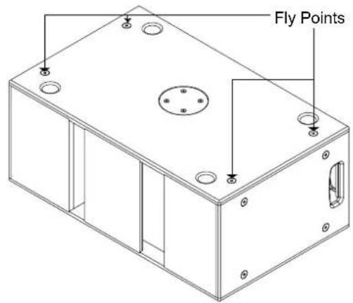
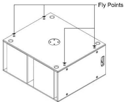
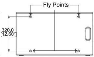
Tannoy VSX subwoofers can be flown with high quality VEB M10 eyebolts with collar to BS4278:1984. The loudspeaker is equipped with internal angle plates, which also double as the flying points, and directly accept VEB M10 eyebolts.
To install the VEB M10 eyebolts, remove the original M10 counter sunk screws from the locations where VEB M10 eyebolts are to be installed. Replace these counter sunk M10 screws with the VEB M10 eyebolts.
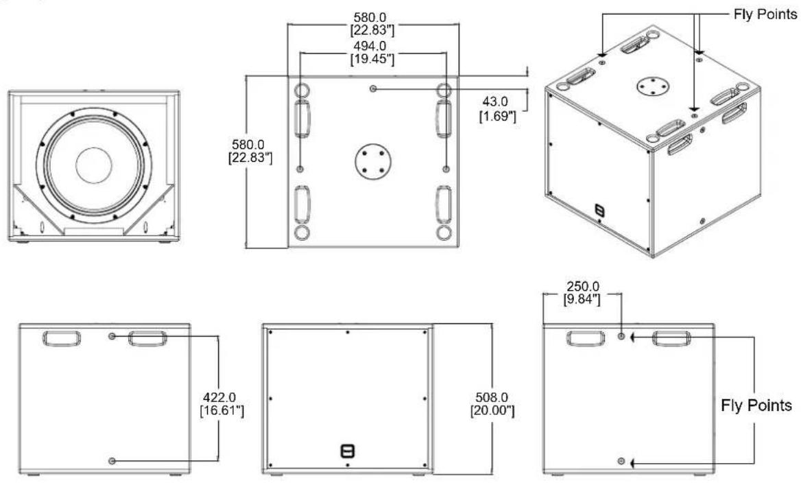
Important: It is imperative for safety reasons that two eyebolts, each linked to two independently fixed straps, are used per cabinet. VEB eyebolts should be installed into the fly points as indicated in the following illustrations. Never suspend one enclosure from another to form an array or cluster using these fittings. Never attempt to use formed eyebolts (formed from a steel rod and bent into an eye).
12. Dimensions
VSX 10BP

12. Dimensions
VSX 8.2BP
![725.0 [28.54"] 640.0 [25.20"] 450.0 [17.72"] 280.0 [11.02"]](/content/2026/06/1345411/images/e48eda5c2a94be11d9a9d3b4575791269b36ed17d4798f587f298823ea81b732.jpg)

![300.0 [11.81"]](/content/2026/06/1345411/images/1ceef243ff14c3547ce6a78e25d3a05e49b62fcca8871ed6a28b517307ea0483.jpg)
![Fly Points 215.0 [8.46"]](/content/2026/06/1345411/images/7fcf6ced6017272b7e7ba1bf0de07ae95c0ac25179ede82abe726a019a36f7e4.jpg)

natural_image
Top-down schematic of a device layout with central connector and two side handles (no text or symbols)VSX 12.2BP
![830.0 [32.68"] 750.0 [29.53"] 450.0 720.0 [17.72"][28.35"]](/content/2026/06/1345411/images/1a9d456fb906e11b7926a803c39aa5598008403c53a6c5421f2e8a842527c0a6.jpg)
![400.0 [15.75"]](/content/2026/06/1345411/images/877f6b75823506abdc0b86c1f51343ee6043501d08bbf9510c3f2f5fbb5dd0e5.jpg)

natural_image
Top-down schematic of a device casing with internal components and two side handles (no text or symbols)12. Dimensions
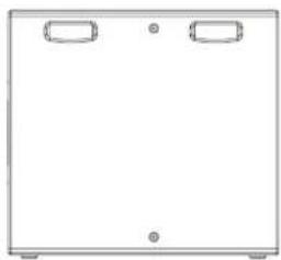
VSX 15DR
VSX 18DR
natural_image
Technical line drawing of a circular mechanical component with mounting brackets and centerlines (no text or symbols)![650.0 [25.59"] 43.0 [1.69"] 650.0 [25.59"] 564.0 [22.20"]](/content/2026/06/1345411/images/2bd1eb30440d6f6e088a23c8f87a84db407cc54c946d802422f894f0c3f24092.jpg)

natural_image
Simple line drawing of a rectangular box with two side handles and a small circular mark at the bottom (no text or symbols)![588.0 [23.15"]](/content/2026/06/1345411/images/d467c054248c299a05bdf14b1e5f022466358117c2bf1df3cb96d9cca212a796.jpg)
![290.0 [11.42"] Fly Points](/content/2026/06/1345411/images/a97458f0f6fdd51c8d5054e8bba5eff8a7e47d6651d81f76250ca6214cd21990.jpg)
13. Technical Specifications
| VSX 10BP | VSX 8.2BP | VSX 12.2BP | VSX 15DR | VSX 18DR | |
| Performance | |||||
| System type | Band-Pass Subwoofer | Band-Pass Subwoofer | Band-Pass Subwoofer | Direct Radiating Subwoofer | Direct Radiating Subwoofer |
| Frequency response (-3 dB)(1) | 42 Hz - 110 Hz 46 Hz - 160 Hz 40 Hz - 160 Hz 45 Hz - 3 kHz 40 Hz - 3 kHz | ||||
| Frequency response (-10 dB)(1) | 36 Hz - 130 Hz 38 Hz - 200 Hz 35 Hz - 200 Hz 36 Hz - 4 kHz 32 Hz - 4 kHz | ||||
| System sensitivity (1 W @1 m)(2) | 93 dB(1 W = 2.83 V for 8 ohms) | 97 dB(1 W = 2.83 V for 8 ohms) | 100 dB(1 W = 2 V for 4 ohms) | 97 dB(1 W = 2.83 V for 8 ohms) | 99 dB(1 W = 2.83 V for 8 ohms) |
| Power Handling | |||||
| Average (2) | 200 W 400 W 800 W 800 W 1000 W | ||||
| Programme | 400 W 800 W 1600 W 1600 W 2000 W | ||||
| Peak | 800 W 1600 W 3200 W 3200 W 4000 W | ||||
| Recommended amplifier power | 400 W @ 8 ohms 800 W @ 8 ohms 1600 W @ 4 ohms 1600 W @ 8 ohms 2000 W @ 8 ohms | ||||
| Rated maximum SPL (2) | |||||
| Average | 116 dB 123 dB 129 dB 126 dB 129 dB | ||||
| Peak | 122 dB 129 dB 135 dB 132 dB 135 dB | ||||
| Nominal impedance | 8 ohms | 8 ohms | 4 ohms | 8 ohms | 8 ohms |
| Driver complement | 250 mm (10")Bass driver | 2 x 200 mm (8")Bass drivers | 2 x 300 mm (12")Bass drivers | 1 x 380 mm (15")Bass driver | 1 x 460 mm (18")Bass driver |
| Recommended crossover | 80 Hz - 110 Hz,24 dB / octaveRecommendedHigh-pass filter -40 Hz, 24 dB / octave | 80 Hz - 150 Hz,24 dB / octaveRecommendedHigh-pass filter -40 Hz, 24 dB / octave | 80 Hz - 150 Hz,24 dB / octaveRecommendedHigh-pass filter -38 Hz, 24 dB / octave | 80 Hz - 500 Hz,24 dB / octaveRecommendedHigh-pass filter -40 Hz, 24 dB / octave | 80 Hz - 300 Hz,24 dB / octaveRecommendedHigh-pass filter -35 Hz, 24 dB / octave |
| Distortion | |||||||||||
| 10% full power (28.3 V) | Harmonics | Harmonics | Harmonics | Harmonics | Harmonics | ||||||
| 2nd | 3rd | 2nd | 3rd | 2nd | 3rd | 2nd | 3rd | 2nd | 3rd | ||
| 1% full power (8.9 V) | 50 Hz | 2.24% | 1.95% | 3.72% | 3.10% | 1.38% | 0.62% | 1.22% | 1.18% | 1.11% | 0.48% |
| 100 Hz | 1.17% | 0.47% | 0.40% | 0.35% | 1.29% | 0.14% | 0.40% | 0.30% | 0.41% | 0.44% | |
| 50 Hz | 0.67% | 0.57% | 0.52% | 0.91% | 0.32% | 0.18% | 0.47% | 0.50% | 0.37% | 0.93% | |
| 100 Hz | 0.42% | 0.49% | 0.19% | 0.15% | 0.29% | 0.16% | 0.15% | 0.17% | 0.11% | 0.15% | |
| Construction | |||||
| Enclosure | 61 litres, 15 mm birch plywood, internally braced | 79 litres, 15 mm birch plywood, internally braced | 194 litres, 15 mm birch plywood, internally braced | 138 litres, 18 mm birch plywood, internally braced | 206 litres, 18 mm birch plywood, internally braced |
| Finish | Textured black or white paint (custom colours on request) | Textured black or white paint (custom colours on request) | Textured black or white paint (custom colours on request) | Textured black or white paint (custom colours on request)Powder coated perforated steel grille, Aimet cloth behind | Textured black or white paint (custom colours on request)Powder coated perforated steel grille, Aimet cloth behind |
| Connectors | 2 x speakON NL4MP and Barrier strip | 2 x speakON NL4MP and Barrier strip | 2 x speakON NL4MP and Barrier strip | 2 x speakON NL4MP and Barrier strip | 2 x speakON NL4MP and Barrier strip |
| Fittings | 8 x M10 Flying inserts (landscape mounting portrait only if ground stacked) | 12 x M10 Flying inserts (portrait or landscape mounting) | 12 x M10 Flying inserts (portrait or landscape mounting) | 12 x M10 Flying inserts (portrait or landscape mounting) | 12 x M10 Flying inserts (portrait or landscape mounting) |
| 1 x Integrip carrying handle | 2 x Integrip carrying handles | 2 x Integrip carrying handles | 4 x Integrip carrying handles | 4 x Integrip carrying handles | |
| Blanking plate for optional VTH pole mount | Blanking plate for optional VTH pole mount | Blanking plate for optional VTH pole mount | Blanking plate for optional VTH pole mount | Blanking plate for optional VTH pole mount | |
| Dimensions | W: 460 mm (18.1")H: 300 mm (11.8")D: 590 mm (23.2") | W: 725 mm (28.5")H: 300 mm (11.8")D: 450 mm (17.7") | W: 830 mm (32.7")H: 400 mm (15.7")D: 720 mm (28.3") | W: 580 mm (22.8")H: 508 mm (20.0")D: 580 mm (22.8") | W: 650 mm (25.6")H: 588 mm (23.1")D: 650 mm (25.6") |
| Weight | 18.5 kg (40.8 lbs) | 25.5 kg (56.3 lbs) | 40.5 kg (89.3 lbs) | 35.5 kg (78.4 lbs) | 45 kg (99.2 lbs) |
- Average over stated bandwidth. Measured at 1 metre on axis.
- Unweighted pink noise input, measured at 1 metre in half space.
A full range of measurements, performance data, and Ease™ Data can be downloaded from www.tannoypro.com
New materials or manufacturing methods introduced through Tannoy's policy of continuous research and development may result in variances; however, performance will meet or exceed published specifications, which Tannoy reserves the right to alter without prior notice.
14. Service Parts & Accessories
| Part number Description | |
| 7900 1344 VSX 8.2BP Bass | Driver |
| 7900 0756 VSX 10BP Bass | Diver |
| 7900 1291 VSX 12.2BP Bass Driver | |
| 7900 1073 VSX 15DR Bass | Driver |
| 7900 0599 VSX 18DR Bass | Driver |
| 7900 1345 VSX 12.2BP Recone Kit | |
| 7900 1074 VSX 15DR Recone Kit | |
| 7900 0603 VSX 18DR Recone Kit | |
| 8001 2860 VTH Secur ET – Top Hat (Black) | |
| 8001 2870 VTH Secur ET – Top Hat (White) | |
| 8001 2820 VEB Secur ET – Eyebolts M10 | |
15. Warranty
No maintenance of the VSX Series loudspeakers is necessary.
As part of the MUSIC Group, Tannoy is committed to providing the highest quality products, service and user experience for our customers. One element of this commitment is our after sales support which now incorporates extended Limited Warranty. In the event of any concern that is not addressed by this extended Limited Warranty we would ask you to contact us at care@music-group.com
For full warranty details including the extended Limited Warranty, please visit http://www.music-group.com/warranty.aspx and register your purchase online at www.music-group.com or ww.tannoy.com
16. EU Declaration of Conformity
(in accordance with ISO/IEC 1750-1)
Document No: CE-VSX-1
We: Music Group Innovation SC Ltd Rosehall Industrial Estate, Coatbridge, ML5 4TF, United Kingdom
In accordance with the following Directive(s):
2004/108/RC Electromagnetic Compatibility (EMC)
2011/65/EU Restriction of the use of certain hazardous substances (RoHS)
Hereby declare that:
Type of equipment Professional loudspeakers
Range name VSX
Models VSX 10BP, VSX 8.2BP, VSX 12.2BP, VSX 15DR, VSX 18DR
Is/are in conformity with the requirements of the following documents:
Ref. No Title Edition
BS EN 55103-1 Electromagnetic compatibility. Product family standard for audio, video, audio-visual and entertainment lighting control apparatus 2009 for professional use. Emissions
BS EN 55103-2 Electromagnetic compatibility. Product family standard for audio, video, audio-visual and entertainment lighting control apparatus 2009 for professional use. Immunity
Name: Philippe Robineau
Position: Director of Engineering
Done at: Coatbridge
Date: 23/11/2015

Director of Engineering
Tannoy
23 November 2015
CE

natural_image
Completely black image with no visible content, text, or symbols.tannoypro.com


- High-performance subwoofers
- Important Safety Instructions
- SAFETY WARNING
- AVERTISSEMENT DE SECURITE
- Introduction
- Unpacking
- Preliminary Recommendation
- Cables and Connectors
- Polarity Checking
- Amplification & Power Handling
- Equalisation and Positioning
- Active Crossover Settings
- Rigging and Safety Procedures
- Dimensions
- Technical Specifications
- Service Parts & Accessories
- Warranty
- EU Declaration of Conformity
Brand : TANNOY
Model : VSX 15DR
Category : Subwoofer