
RB38T650EB1 - Refrigerator SAMSUNG - Free user manual and instructions
Find the device manual for free RB38T650EB1 SAMSUNG in PDF.


| Product Type | Refrigerator with Freezer |
| Model | RB38T650EB1 |
| Brand | Samsung |
| Total Net Capacity | 390 L (approx.) |
| Refrigerator Capacity | 275 L (approx.) |
| Freezer Capacity | 115 L (approx.) |
| Energy Efficiency Class | A+ (EU) |
| Annual Energy Consumption | 250 kWh (approx.) |
| Dimensions (H x W x D) | 2030 x 595 x 658 mm (approx.) |
| Net Weight | 68 kg (approx.) |
| Power Supply | 220-240 V, 50 Hz |
| Climate Class | SN-T (Subnormal to Tropical) |
| Refrigerant | R600a (isobutane) |
| Cooling System | No Frost (frost-free) |
| Compressor Type | Digital Inverter (variable speed) |
| Key Functions | Cool Select Zone, Twin Cooling Plus, Metal Cooling |
| Control Type | Electronic with LED display |
| Noise Level | 35 dB (approx.) |
| Defrosting | Automatic (No Frost) |
| Handle Type | Recessed handle |
| Shelves Material | Tempered glass |
| Interior Light | LED |
| Spare Parts Availability | 7 years after end of production (EU regulations) |
| Repairability Index (France) | 8.0/10 (approx.) |
Frequently Asked Questions - RB38T650EB1 SAMSUNG
User questions about RB38T650EB1 SAMSUNG
0 question about this device. Answer the ones you know or ask your own.
Ask a new question about this device
Download the instructions for your Refrigerator in PDF format for free! Find your manual RB38T650EB1 - SAMSUNG and take your electronic device back in hand. On this page are published all the documents necessary for the use of your device. RB38T650EB1 by SAMSUNG.
USER MANUAL RB38T650EB1 SAMSUNG

SAMSUNG
Contents
- Open the door and find the supplied fastener (gray block).
- Unpack the fastener and place it on the back of the refrigerator as shown. It improves airflow to the back wall and reduces energy consumption.
STEP 3 Floors
- The installation surface must support a fully loaded refrigerator.
- To protect the floor, place a large piece of cardboard under each refrigerator leg.
- Once you have placed the refrigerator in position, do not move it unless necessary to protect the floor. If necessary, use thick paper or some fabric, such as an old carpet, along the moving path.

Installation
STEP 4 Adjusting the leveling legs
CAUTION
To adjust the height of the left side of the refrigerator:
Insert a flat-head screwdriver into the leveler of the front left leg. Turn the leveler clockwise to raise the refrigerator, or counterclockwise to lower it.

To adjust the height of the right side of the refrigerator:
Insert a flat-head screwdriver into the leveler of the front right leg. Turn the leveler clockwise to raise the refrigerator, or counterclockwise to lower it.

STEP 5 Initial settings


- Reinstall the water container and close the door. Make sure the water inlet is facing forward.

Removing the flexible divider
While pressing the rear side, pull up the front side and remove it.
Humidity Fresh+ Zone (certain models only)

The Humidity Fresh+ Zone allows you to adjust humidity. Turn the control dial left or right to set the desired humidity.
Operations
To get more space, you can remove all drawers and place the refrigerator shelf on the bottom drawer, as this does not affect thermal and mechanical characteristics. The nominal freezer volume is calculated with these drawers removed.
(For Singapore models, the nominal volume is calculated only with the top and middle drawers removed.)

- Remove the tape attached to the shelf.

- Remove all drawers to assemble the shelf.
- Insert the freezer shelf so that the label "Front" faces upward. If the "Front" label is not visible, first insert the protruding part of the shelf as shown in the figure.
CAUTION
- Place the handle on the opposite side of the door and, using a Phillips screwdriver and screws, install the handle.
Maintenance

- Install the screw covers.
Reversing the door swing (certain models only)
⚠ WARNING
- Two people are required to tilt/lay down the refrigerator.
- Unplug the power cord before reversing the door swing.
Required tools (not provided)


Upper left hinge cover Upper right door cover (selected models only)
CAUTION


- Carefully lift the top cover (A) and place it on the top of the refrigerator.
- Be careful when lifting the top cover (A). There are connected cables underneath.
- Remove the cable and cable connector from the holder located under the top cover.
- This step does not apply to all models.
CAUTION


- Open the refrigerator door, then lift it to remove it from the middle hinge. Keep the door in a safe place.
CAUTION
- Remove the middle hinge screw covers (A) and use a Phillips screwdriver to remove the screw (B).
- On the opposite side, use a Phillips screwdriver to attach the screw (B), then install the middle hinge screw covers (A).

- Remove the lower hinge screw cover (A) and install it on the opposite side.

- On the bottom side of the freezer door, remove the door stopper (A) and install it on the opposite side of the door.
- Use a Phillips screwdriver to remove and attach the screw that secures the door stopper (A). - Turn the door stopper (A) before installing it on the opposite side.
![graph TD A["Point A"] --> B["Point B"] style A fill:#f9f,stroke:#333 style B fill:#ccf,stroke:#333](/content/2026/06/1345393/images/6725a5d3c2b45223db49ef22a93fea9463c3b1f3847e172e3ef4582d76958dfb.jpg)

![graph TD A["A"] --> C["C"] B["B"] --> C["C"] C["C"] --> D["D"] D["D"] --> E["E"] E["E"] --> F["F"] F["F"] --> A["A"] style A fill:#f9f,stroke:#333 style B fill:#f9f,stroke:#333 style C fill:#ccf,stroke:#333 style D fill:#ccf,stroke:#333 style E fill:#ccf,stroke:#333 style F fill:#ccf,stroke:#333](/content/2026/06/1345393/images/1c9b0f7ecb23292fcb9fdbc26f52630783e9fbd11f1de25fd396b503fcb1efbf.jpg)
- On the top side of the freezer door, reverse the position of the gasket (A) and the gasket cover (B).
- Attach the middle hinge (A) to the opposite side from where it was removed.


- Turn the leveling foot to the opposite side from the one where the lower hinge (A) was removed. Then place the lower hinge (A) on the bracket.
- Install the freezer door.
a. Place the freezer door on the lower hinge (A). Position the door perpendicular to the refrigerator body. b. Push the freezer door down to insert the middle hinge (B) into the gasket (C) on the top side of the freezer door.
CAUTION
Do not push the door too hard. During this step, check that the lower hinge (A) is seated on the bracket on the bottom side of the refrigerator.
NOTE
When attaching the freezer door, adjust the leveling feet to align the refrigerator. (For detailed instructions, refer to the section “STEP 4 Adjusting the Leveling Feet” on page 32.)
- Using a Phillips screwdriver, secure the lower hinge (A) with screws. Then close the freezer door.


- On the bottom side of the refrigerator door, remove all parts on the left and right sides.
a. Using a Phillips screwdriver, remove the screws. b. Remove the automatic door closer (A), the gasket (B), and the door stopper (C) on one side, and the lower refrigerator door cover (D) on the other.
- Replace the sides with all removed parts.
a. Place the door stopper (C), the gasket (B), and the automatic door closer (A) on the opposite side from where they were removed. b. Secure the door stopper (C) and the automatic door closer (A) with screws using a Phillips screwdriver. c. Place the lower refrigerator door cover (D) on the opposite side from where it was removed. d. Secure the lower refrigerator door cover (D) with a screw using a Phillips screwdriver.
CAUTION


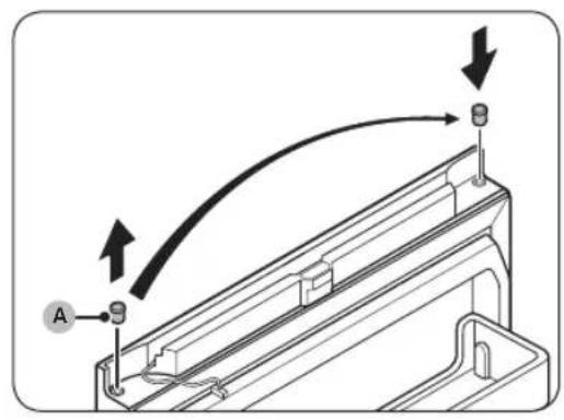
- On the top side of the refrigerator door, remove the cable cover (A).
- Carefully lift one side of the cable cover (A) and pull to remove it from the door.
- This step does not apply to all models.
- Remove the upper right hinge cover (A) and the upper left door cover (B).
- This step does not apply to all models.
NOTE

- Turn the upper hinge.
a. Using a screwdriver (11 mm), disassemble the shaft (A) and the washer (B). b. Turn the upper hinge (C), then reassemble the washer (B) and the shaft (A).
CAUTION
- Be careful not to drop the shaft (A) or injure your fingers when removing or installing the shaft (A).
- Make sure the washer (B) is in the correct position. If the shaft is secured without the washer (B), the door may fall off and cause injury.
- Place the refrigerator door on the middle hinge (A).
CAUTION
To prevent the door from falling, hold it firmly while attaching the top hinge.
- Place the top hinge (A) on the opposite side from where it was removed.
Maintenance
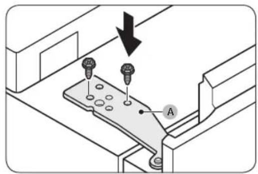
- Remove the gap cover (A) from the top cover (B) and place it on the opposite side.

- Under the top cover, pull the cable connector (A) from the holder and move it to the holders on the opposite side.
- This step does not apply to all models.

- Move the cable connector (A) on the refrigerator door to the opposite side.
- This step does not apply to all models.

Maintenance


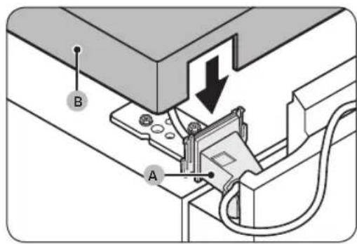

- Reconnect the cable connector (A).
- This step does not apply to all models.
CAUTION
Check that the cable connectors are properly connected. Otherwise, the screen will not work.
- Place the cable and cable connector (A) on the holder under the top cover.
- This step does not apply to all models.
- Place the supplied upper left hinge cover (A) on the upper hinge and install the top cover (B).
- Place the cables and connectors into the upper left hinge cover (A) and the top cover (B). (Some models do not have cables, and this may not apply to those models.)
- While the refrigerator doors are closed, replace the top cover (A) and secure it with screws and a Phillips screwdriver.
CAUTION
Be careful not to damage the cables while securing the top cover (A).
Maintenance

- Place the supplied upper right door cover (A) on the opposite side of the door hinge.
- This step does not apply to all models.

- Route the cable from the refrigerator door into the space under the cable cover (A).
- This step does not apply to all models.

- Replace the cable cover (A) on the refrigerator door.
- This step does not apply to all models.
- Open and close the refrigerator door several times to check that everything is in order.

- Remove the gaskets from the refrigerator and freezer doors, rotate the doors 180°, and then replace the gaskets.
CAUTION
Check that the gaskets are properly seated on the doors. Otherwise, the appliance may operate noisily or moisture may form, which can affect the operation of the appliance.
NOTE
- When you reverse the refrigerator door, adjust the leveling feet to align the refrigerator. (For detailed instructions, refer to the section "STEP 4 Adjusting the Leveling Feet" on page 32.)
- To return the doors to their original position, repeat the steps. Note that in this case, the doors, hinges, and other parts will have the opposite orientation to that described in these steps.
Maintenance
Handling and care
Shelves / shelf and shelf (certain models only)
- Pull the shelf (or shelf and shelf) out a little. Then pull it out completely, lifting the rear side.

- Insert the shelf (or shelf and shelf) diagonally to remove it.
Serbian56
Foldable shelf (certain models only)
- Pull the front half of the shelf.

- Pull the foldable shelf out a little. Then pull it out completely, lifting the rear side.
- To remove the shelf, tilt it diagonally.


CAUTION
- Do not place food or objects in the front part of the Optimal Fresh+ zone. The door may not close properly and items may fall out onto the floor.
- The shelf must be inserted correctly. Do not install it upside down.
- When returning the shelf, make sure to push it all the way in until it is properly positioned.
- Glass containers may scratch the surface of the glass shelves.
Maintenance
Cleaning
Maintain the cables and exposed parts on the rear panel by vacuuming the panel once or twice a year.
CAUTION
Do not remove the rear panel cover. Electric shock may occur.
Replacement
LED lamps
To replace the refrigerator lamps, contact your local Samsung service center.

WARNING
- Lamps cannot be serviced by users. Do not attempt to replace the lamp yourself. Electric shock may occur.
Lamp (light source)
- Model RB34: RA-C00K4BAA
- Model RB38: RA-C00K3BAA
- Pair installation may increase energy consumption.

| 01 preporučuje se više od 50 mm |
| 02 105° |
| 03 1250 mm |
| 04 1212 mm |
| 05 Gornji nosač |
| 06 Obloga |
| 07 Smer instalacije |
Required tools (not provided)


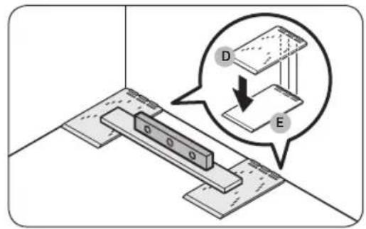

1. Check the floor level.
- Use a level to check the floor level where the two rear wheels of the refrigerator will be placed.
2. Place the A/S templates (D) and check the level.
- Place the two provided A/S templates (D) on the floor where the two rear wheels of the refrigerator will be placed, then check the level.
- If the floor is not level, place the provided leveling adjustment pads (E) under the A/S templates (D) so that the refrigerator is placed on a level surface.
- Once you have arranged all the elements needed for leveling, peel off the double-sided adhesive tape on the bottom of each part and attach the part to its final position.


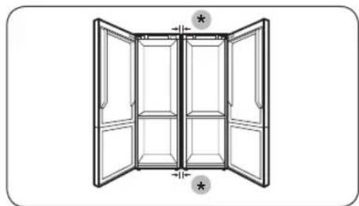
(*): 15 mm (RB34) / 7 mm (RB38)

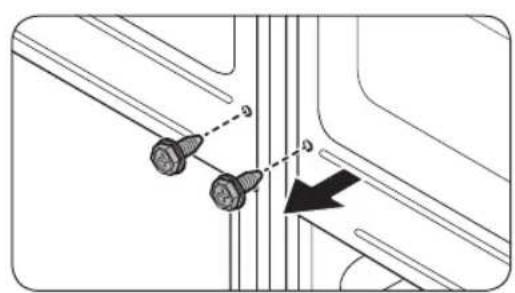
- Use the screws removed in step 8 to attach the rear bracket (H).
- Check the distance between the refrigerators.
- After attaching the upper and lower brackets, check that the distance between the refrigerators is 7 or 15 mm at the top and bottom.
NOTE
If the distance between the refrigerators is greater than 7 or 15 mm, there may be less space between the refrigerators and the walls (or kitchen cabinets), which can obstruct the opening of the doors.
- Push the refrigerators toward the walls (or kitchen cabinets).
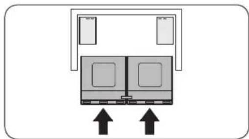
- Have two people push the refrigerators, attached with brackets, toward the walls (or kitchen cabinets) at the same time.
NOTE
If two people do not push the refrigerators evenly, the rear parts of the refrigerators may separate or move from their designated positions.
- Adjust the height of the refrigerators.
- Turn the leveling foot to the right or left to adjust the height of the refrigerator so that it is level with the walls (or kitchen cabinets).
Maintenance


- Insert the filler (C) between the refrigerators.
- Open the doors and insert the filler (C) between the refrigerators.
NOTE
Refer to the enlarged view of the filler in the figure to identify which side is the top of the filler.

SAMSUNG
Contents
Correct disposal of the product (Waste Electrical & Electronic Equipment)
- Open the doors and find the provided spacer (gray plate).
- Unpack the spacers and attach them to the back of the refrigerator as shown. They facilitate ventilation of the rear wall and reduce electricity consumption.
STEP 3 Shelf


- Hold the grips on both sides of the water tank and lift it to remove it.
- Fill the water tank with drinking water up to the level of 3.5 liters (MAX (maximum level)). You can remove the top cover or the lid and pour in the water.
CAUTION
- The water dispenser is designed for dispensing drinking water. Fill the water tank only with drinking water. Do not fill with other liquids.
- Do not overfill the water tank as this leads to overflow.
NOTE
Before first use, clean the inside of the water tank.
Operations

- Reinsert the water tank and close the door. Make sure that the water outlet of the water tank is facing forward.

- Place a water glass under the water outlet on the dispenser and gently press the dispenser lever to dispense water. Make sure that the water dispenser is unlocked.
CAUTION
• Do not store items on top of the water tank cover. - Do not attempt to fill the water tank if it has not been removed from the door. - Make sure the water tank is properly seated. - Do not use the refrigerator without the water tank. This may reduce performance and efficiency. - To prevent water splashing, make sure the glass is aligned with the dispenser lever.
NOTE
Removing the Flex shelf
Press the rear of the shelf down and simultaneously lift the front to remove it from the drawer.
Humidity Fresh+ (on certain models only)


NOTE
- Use a flat-head screwdriver to remove the screw covers.
- After detaching the handle, reattach the screw covers to the screw holes.
- Use a Phillips screwdriver to remove the screws and detach the handle. Use the specified screws to attach the handle to the opposite side.
- Use a flat-head screwdriver to remove the screw covers on the opposite side of the door.
- Position the handle on the opposite side of the door and secure it with screws using a Phillips screwdriver.
Maintenance

- Attach the screw covers.


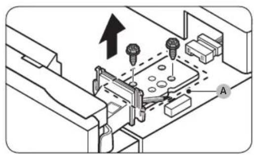
- Gently lift the top cover (A) and place it on the refrigerator.
- Carefully lift the top cover (A). There is a wire underneath the cover.
- Remove the wire and wire connector located on the bracket under the top cover.
- This step may not apply to certain models.
CAUTION

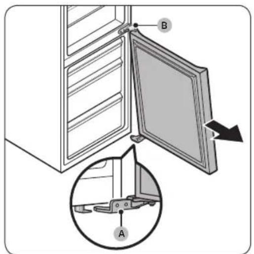
- Remove the screw covers on the middle hinge (A) and then remove the screw (B) with a Phillips screwdriver.
- On the opposite side, tighten the screw (B) with a Phillips screwdriver and then install the screw covers on the middle hinge (A).

- Remove the screw cover on the bottom hinge (A) and place it on the opposite side.

- Remove the door stopper (A) from the bottom of the freezer door and install it on the opposite side of the door.
- Use a Phillips screwdriver to remove and tighten the screw that secures the door stopper (A).
- Turn the door stopper (A) before installing it on the opposite side.

Maintenance

![graph TD A["A"] --> C["C"] B["B"] --> C["C"] C["C"] --> D["D"] D["D"] --> E["E"] E["E"] --> F["F"] F["F"] --> A["A"] style A fill:#f9f,stroke:#333 style B fill:#f9f,stroke:#333 style C fill:#ccf,stroke:#333 style D fill:#ccf,stroke:#333 style E fill:#ccf,stroke:#333 style F fill:#ccf,stroke:#333](/content/2026/06/1345393/images/9beecad5024f6196aee24474f97cdf968cbc403eea4d8314266b28e73930a337.jpg)

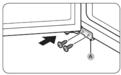
- Turn the leveling foot on the opposite side of the removed bottom hinge (A). Then install the bottom hinge (A) on the bracket.
- Install the freezer door.


- Replace the position of the upper hinge.
a. Using a wrench (11 mm), disassemble the shaft (A) and the plate (B). b. Turn the upper hinge (C) and then reattach the plate (B) and the shaft (A).
CAUTION
- Be careful not to drop the shaft (A) or injure your fingers when removing or assembling the shaft (A).
- Check that the plate (B) is properly positioned. If you secure the shaft without the plate (B), the door may fall and cause injury.
- Place the refrigerator door on the middle hinge (A).
CAUTION
- Secure the upper hinge (A) with screws using a ratchet wrench (8 mm).

- Remove the slot cover (A) from the top cover (B) and place it on the opposite side.


- Reconnect the wire connector (A).
- This step may not apply to certain models.
CAUTION
- Push the wires from the refrigerator door into the space under the wire cover (A).
This step may not apply to certain models.

- Put the wire cover (A) back on the refrigerator door.
This step may not apply to certain models.
- Detach the refrigerator and freezer door gaskets and reattach them after turning them 180°.
CAUTION
- Gently pull out the shelf (or Rack & Shelf). Then remove it from the refrigerator while lifting the rear side of the shelf.

- Tilt the shelf (or Rack & Shelf) diagonally to remove it.
Croatian56-


- Slide the front part of the shelf in with a sliding motion.
- Gently pull out the folding shelf. Then remove it from the refrigerator while lifting the rear side of the shelf.
- Tilt the shelf diagonally to remove it.
CAUTION
- Do not place food or objects in front of the Optimal Fresh+ drawer. The doors may not close properly, and objects may fall to the floor.
- The shelf must be inserted properly. Do not place it upside down.
- When reinserting the shelf, make sure to push it all the way in so that it sits in place.
- Glass containers can scratch the surface of glass shelves.
Maintenance
Cleaning
Inside and outside
⚠ WARNING
To keep the cables and exposed parts of the refrigerator's back panel clean, vacuum it once or twice a year.
CAUTION
Do not remove the back panel cover. This can cause electric shock.
Replacement
LED bulb


- Attach the foams to maintain the gap between two refrigerators.
NOTE
Attach the T5 polyethylene foam (G) only to the BMF model (bottom-mount freezer). (In case you install two different types of refrigerators in a pair.)
A. Pair installation of RB38 models:
- Attach the T5 polyethylene foam (G). • For the position of the foam, see the figure.
B. Pair installation of model RB34:


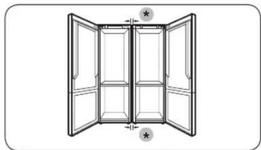
(*): 15 mm (RB34) / 7 mm (RB38)
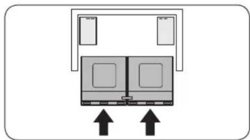

- Use the screws removed in step 8 to attach the rear bracket (H).
- Check the gap between the refrigerators.
- After attaching the top and bottom brackets, check that there is at least 7 or 15 mm of clearance at the top and bottom between the two refrigerators.
NOTE
If the gap between the two refrigerators is larger than 7 or 15 mm, there may be less space between the refrigerators and the walls (or cabinets), which may interfere with opening the doors.
- Push the refrigerators into the walls (or cabinets).
- Have two people push the refrigerators, which are attached with brackets, into the walls (or cabinets) at the same time.
NOTE

- Insert the frame screw rod (C) between the refrigerators.
- Open the doors and insert the frame screw rod (C) between the refrigerators.
NOTE
Look at the larger part of the frame screw rod in the figure to identify which side is the top.
Refrigerator
User manual
RB3*T*/RL3*T*/RB3*A*/RL3*A*
SEAD
Free Standing Appliance


SAMSUNG
Contents
Safety information 3
What you need to know about the safety instructions 3 Important safety symbols and precautions: 5 Important safety precautions 6 Severe warning signs for transportation and site 9 Critical installation warnings 10 Installation cautions 13 Critical usage warnings 14 Usage cautions 19 Cleaning cautions 22 Critical disposal warnings 24 Additional tips for proper usage 25 Instructions about the WEEE 26
Installation 27
Refrigerator at a glance 27 Step-by-step installation 28
Operations 34
Control panel 34 Special features 37
Maintenance 41
Reversing the door handle position (For models with bar handles) 41 Door reversal (applicable models only) 42 Handle and care 56 Cleaning 58 Replacement 59 Pair installation (applicable models only) 60
Troubleshooting 67
General 67 Do you hear abnormal sounds from the refrigerator? 69
Appendix 71
Safety Instruction 71 Install Instruction 71 Temperature Instruction 72 Information for model and ordering spare parts 75
English 2
Safety information
Before using your new Samsung Refrigerator, please read this manual thoroughly to ensure that you know how to operate the features and functions that your new appliance offers safely and efficiently.
What you need to know about the safety instructions
- Warnings and Important Safety Instructions in this manual do not cover all possible conditions and situations that may occur. It is your responsibility to use common sense, caution, and care when installing, maintaining, and operating your appliance.
- Because these following operating instructions cover various models, the characteristics of your refrigerator may differ slightly from those described in this manual and not all warning signs may be applicable. If you have any questions or concerns, contact your nearest service center or find help and information online at www.samsung.com.
- R-600a or R-134a is used as a refrigerant. Check the compressor label on the rear of the appliance or the rating label inside the fridge to see which refrigerant is used for your appliance. When this product contains flammable gas (Refrigerant R-600a), contact your local authority in regard to safe disposal of this product.
- In order to avoid the creation of a flammable gas-air mixture if a leak in the refrigerating circuit occurs, the size of the room in which the appliance may be sited depends on the amount of refrigerant used.
Safety information
- Never start up an appliance showing any signs of damage. If in doubt, consult your dealer. The room must be 1 m³ in size for every 8 g of R-600a refrigerant inside the appliance.
The amount of refrigerant in your particular appliance is shown on the identification plate inside the appliance.
- Refrigerant squirting out of the pipes could ignite or cause an eye injury. When refrigerant leaks from the pipe, avoid any naked flames and move anything flammable away from the product and ventilate the room immediately.
- Failing to do so may result in fire or explosion.
- To avoid contamination of food, please respect the following instructions:
- Opening the door for long periods can cause a significant increase of the temperature in the compartments of the appliance.
- Clean regularly surfaces that can come in contact with food and accessible drainage systems.
- Clean water tanks if they have not been used for 48 h; flush the water system connected to a water supply if water has not been drawn for 5 days.
- Store raw meat and fish in suitable containers in the refrigerator, so that it is not in contact with or drip onto other food.
- Two-star frozen-food compartments are suitable for storing pre-frozen food, storing or making icecream and making ice cubes.
- One-, two- and three-star compartments are not suitable for the freezing of fresh food.
- If the refrigerating appliance is left empty for long periods, switch off, defrost, clean, dry, and leave the door open to prevent mould developing within the appliance.
Important safety symbols and precautions:
Please follow all safety instructions in this manual. This manual uses the following safety symbols.

WARNING
Hazards or unsafe practices that may result in severe personal injury, property damage, and/or death.

CAUTION
Hazards or unsafe practices that may result in severe personal injury and/or property damage.

NOTE
Useful information that helps users understand or benefit from the refrigerator.
These warning signs are here to prevent injury to you and others.
Please follow them carefully.
After reading this section, keep it in a safe place for future reference.
Safety information
Important safety precautions

Warning; Risk of fire / flammable materials
WARNING
- When positioning the appliance, ensure the supply cord is not trapped or damaged.
- Do not locate multiple portable socket-outlets or portable power supplies at the rear of the appliance.
- Fill with potable water only.
- Connect to potable water supply only.
- Keep ventilation openings, in the appliance enclosure or in the built-in structure, clear of obstruction.
- Do not use mechanical devices or any other means to accelerate the defrosting process, other than those recommended by the manufacturer.
- Do not damage the refrigerant circuit.
- Do not use electrical appliances inside the food storage compartments of the appliance, unless they are of the type recommended by the manufacturer.
- This appliance is not intended for use by persons (including children) with reduced physical, sensory, or mental capabilities, or those who lack experience and knowledge, unless they have been given supervision or instruction concerning the use of the appliance by a person responsible for their safety.
- This appliance can be used by children aged from 8 years and above and persons with reduced physical, sensory or mental capabilities or lack of experience and knowledge if they have been given supervision or instruction concerning use of the appliance in a safe way and understand the hazards involved. Children shall not play with the appliance. Cleaning and user maintenance shall not be made by children without supervision. Children aged from 3 to 8 years are allowed to load and unload refrigerating appliances.
- If the supply cord is damaged, it must be replaced by the manufacturer, its service agent or similarly qualified persons in order to avoid a hazard.
- The socket must be easily accessible so that the appliance can be quickly disconnected from the supply in an emergency.
- It must be outside the area of the rear of the appliance.
- Do not store explosive substances such as aerosol cans with a flammable propellant in this appliance.
- If the product is equipped with LED lamps, do not disassemble the Lamp Covers and LED lamps yourself.
- Contact a Samsung service center.
- Use only the LED lamps provided by the manufacturer or its service agents.
- For the most efficient use of energy, please keep all inner fittings such as baskets, drawers, and shelves in the position supplied by the manufacturer.
- To get the best energy efficiency from this product, please leave all shelves, drawers, and baskets in their original position.
Safety information
How to minimize energy consumption
• Install the appliance in a cool, dry room with adequate ventilation. - Ensure that it is not exposed to direct sunlight and never put it near a direct source of heat (e.g., a radiator). - Do not block any vents or grilles; this is recommended for energy efficiency. - Allow warm food to cool down before placing it in the appliance. - Put frozen food in the refrigerator to thaw. You can then use the low temperatures of the frozen products to cool food in the refrigerator. - Do not keep the door of the appliance open for too long when putting food in or taking food out. - The shorter the time the door is open, the less ice will form in the freezer. - Clean the rear of the refrigerator regularly. Dust increases energy consumption. - Do not set the temperature colder than necessary. - Ensure sufficient air exhaust at the refrigerator base and at the back wall of the refrigerator. Do not cover air vent openings. - Allow clearance to the right, left, back, and top when installing. This will help reduce power consumption and keep your energy bills lower.
• We recommend the following clearance values:
- Right, left, and back sides: more than 50 mm
- Top side: more than 100 mm
This appliance is intended to be used in household and similar applications such as
- staff kitchen areas in shops, offices and other working environments;
- farm houses and by clients in hotels, motels and other residential type environments;
- bed and breakfast type environments;
- catering and similar non-retail applications.
Severe warning signs for transportation and site
WARNING
- When transporting and installing the appliance, care should be taken to ensure that no parts of the refrigerating circuit are damaged.
- Refrigerant leaking from the pipe work could ignite or cause an eye injury. If a leak is detected, avoid any naked flames or potential sources of ignition and air the room in which the appliance is standing for several minutes.
- This appliance contains a small amount of isobutane refrigerant (R-600a), a natural gas with high environmental compatibility that is, however, also combustible. When transporting and installing the appliance, care should be taken to ensure that no parts of the refrigerating circuit are damaged.
Safety information
Critical installation warnings
WARNING
- Do not install the refrigerator in a damp location or place where it may come in contact with water.
- Deteriorated insulation on electrical parts may cause an electric shock or fire.
- Do not place this refrigerator in direct sunlight or expose it to the heat from stoves, room heaters, or other appliances.
- Do not plug several appliances into the same multiple power strip. The refrigerator should always be plugged into its own individual electrical outlet which has a voltage rating that matches the voltage listed on the refrigerator's rating plate.
- This provides the best performance and also prevents overloading of house wiring circuits, which could cause a fire hazard from overheated wires.
- If the wall socket is loose, do not insert the power plug.
- There is a risk of electric shock or fire.
- Do not use a power cord that has cracks or abrasion damage along its length or at either end.
- Do not bend the power cord excessively or place heavy objects on it.
- Do not pull or excessively bend the power cord.
- Do not twist or tie the power cord.
- Do not hook the power cord over a metal object, place a heavy object on the power cord, insert the power cord between objects, or push the power cord into the space behind the appliance.
- When moving the refrigerator, be careful not to roll over or damage the power cord.
- This may result in an electric shock or fire.
- Never unplug your refrigerator by pulling on the power cord. Always grip the plug firmly and pull straight out from the outlet.
- Damage to the cord may cause a short-circuit, fire, and/or electric shock.
- Do not use aerosols near the refrigerator.
- Using aerosols near the refrigerator may cause an explosion or fire.
- Do not install this appliance near a heater or inflammable material.
- Do not install this appliance in a location where gas may leak.
- This may result in an electric shock or fire.
- This refrigerator must be properly located and installed in accordance with the instructions in this manual before you use it.
- Connect the power plug in the proper position with the cord hanging down.
- If you connect the power plug upside down, the wire can get cut off and cause a fire or electric shock.
- Make sure that the power plug is not crushed or damaged by the back of the refrigerator.
- Keep the packing materials out of reach of children.
- There is a risk of death from suffocation if a child puts the packing materials on his or her head.
Safety information
- Do not install this appliance in a humid, oily or dusty location, in a location exposed to direct sunlight and water (rain drops).
- Deteriorated insulation of electrical parts may cause an electric shock or fire.
- If any dust or water is in the refrigerator, pull out power plug and contact your Samsung Electronics service center.
- Otherwise there is a risk of fire.
- Do not stand on top of the appliance or place objects (such as laundry, lighted candles, lighted cigarettes, dishes, chemicals, metal objects, etc.) on the appliance.
- This may result in an electric shock, fire, problems with the product, or injury.
- You need to remove all the protective plastic film before you initially plug the product in.
- Children should be supervised to ensure that they do not play with the snap rings used for door adjustment or the water tube clips.
- There is risk of death by suffocation if a child swallows a snap ring or water tube clip. Keep the snap rings and water tube clips out of children's reach.
- The refrigerator must be safely grounded.
- Always make sure that you have grounded the refrigerator before attempting to investigate or repair any part of the appliance. Power leakages can cause severe electric shock.
- Never use gas pipes, telephone lines, or other potential lightning attractors as an electrical ground.
- You must ground the refrigerator to prevent any power leakages or electric shocks caused by current leakage from the refrigerator.
- This may result in an electric shock, fire, explosion, or problems with the product.
- Plug the power plug into the wall socket firmly. Do not use a damaged power plug, damaged power cord, or loose wall socket.
- This may result in an electric shock or fire.
- The fuse on the refrigerator must be changed by a qualified technician or service company.
- Failing to do so may result in an electric shock or personal injury.
Installation cautions
CAUTION
- Allow sufficient space around the refrigerator and install it on a flat surface.
- If your refrigerator is not level, cooling efficiency and durability can be declined.
- Allow the appliance to stand for 2-3 hours before loading foods after installation and turning on.
• We strongly recommend you have a qualified technician or service company install the refrigerator.
- Failing to do so may result in an electric shock, fire, explosion, problems with the product, or injury.
Safety information
Critical usage warnings
WARNING
- Do not insert the power plug into a wall socket with wet hands.
- This may result in an electric shock.
- Do not store articles on the top of the appliance.
- When you open or close the door, the articles may fall and cause personal injury and/or material damage.
- Do not insert hands, feet or metal objects (such as chopsticks, etc.) into the bottom or the back of the refrigerator.
- This may result in an electric shock or injury.
- Any sharp edges may cause a personal injury.
- Do not touch the inside walls of the freezer or products stored in the freezer with wet hands.
- This may cause frostbite.
- Do not put a container filled with water on the refrigerator.
- If spilled, there is a risk of fire or electric shock.
- Do not keep volatile or flammable objects or substances (benzene, thinner, propane gas, alcohol, ether, LP gas, and other such products) in the refrigerator.
- This refrigerator is for storing food only.
- This may result in fire or explosion.
- Children should be supervised to ensure that they do not play with the appliance.
- Keep fingers out of “pinch point” areas. Clearances between the doors and cabinet are necessarily small. Be careful when you open the doors if children are in the area.
- Do not put your fingers or children's fingers between the doors.
- Keep fingers out of the left and right door gaps. Be careful when you open the doors if your fingers are in between the doors.
- Do not let children hang on the door or door bins. A serious injury may occur.
- Do not let children go inside the refrigerator. They could become trapped.
- Do not insert your hands into the bottom area under the appliance.
- Any sharp edges may cause personal injury.
- Do not store pharmaceutical products, scientific materials, or temperature sensitive products in the refrigerator.
- Products that require strict temperature controls must not be stored in the refrigerator.
- If you smell pharmaceutical or smoke, pull out power plug immediately and contact your Samsung Electronics service center.
- If any dust or water is in Refrigerator, pull out power plug and contact your Samsung Electronics service center.
- Otherwise there is a risk of fire.
- Do not let children step on a drawer.
- The drawer may break and cause them to slip.
- Do not leave the doors of the refrigerator open while the refrigerator is unattended and do not let children enter inside the refrigerator.
- Do not allow babies or children go inside the drawer.
- It can cause death from suffocation by entrapment or personal injury.
Safety information
- Do not overfill the refrigerator with food.
- When you open the door, an item may fall out and cause personal injury or material damage.
- Do not spray volatile material such as insecticide onto the surface of the appliance.
- As well as being harmful to humans, it may also result in an electric shock, fire, or problems with the product.
- Never put fingers or other objects into the water dispenser hole, ice chute and ice maker bucket.
- It may cause a personal injury or material damage.
- Do not use or place any substances sensitive to temperature such as flammable sprays, flammable objects, dry ice, medicine, or chemicals near or inside of the refrigerator.
- Do not use a hair dryer to dry the inside of the refrigerator. Do not place a lighted candle in the refrigerator for removing bad odours.
- This may result in an electric shock or fire.
- Fill the water tank, ice tray and water cubes only with potable water (mineral water or purified water).
- Do not fill the tank with tea, juice or sports drink, this may damage the refrigerator.
- Do not stand on top of the appliance or place objects (such as laundry, lighted candles, lighted cigarettes, dishes, chemicals, metal objects, etc.) on the appliance. This may result in an electric shock, fire, problems with the product, or injury. Do not put a container filled with water on the appliance.
- If spilled, there is a risk of fire or electric shock.
Never stare directly at the UV LED lamp for long periods of time.
- This may result in eye strain due to the ultraviolet rays.
- Do not put shelf in upside down. Shelf stopper could not work.
- It may cause a personal injury because of glass shelf drop.
- Keep fingers out of “pinch point” areas. Clearances between the doors and cabinet are necessarily small. Be careful when you open the doors if children are in the area.
- If a gas leak is detected, avoid any naked flames or potential sources of ignition, and air the room in which the appliance is standing for several minutes.
- Do not touch the appliance or power cord.
- Do not use a ventilating fan.
- A spark may result in explosion or fire.
- Bottles should be stored tightly together so that they do not fall out.
- This product is intended only for the storage of food in a domestic environment.
- Never put fingers or other objects into the water dispenser hole, ice chute and ice maker bucket.
- It may cause a personal injury or material damage.
- Do not attempt to repair, disassemble, or modify the refrigerator yourself.
- Do not use any fuse (such as copper, steel wire, etc.) other than a standard fuse.
Safety information
- If your refrigerator needs to be repaired or reinstalled, contact your nearest service center.
- Failing to do so may result in an electric shock, fire, problems with the product, or injury.
- If the refrigerator emits a burning smell or smoke, unplug the refrigerator immediately and contact your Samsung Electronics service center.
- Failing to do so may result in an electric or fire hazard.
- Pull the power plug out of the socket before changing the interior lamps of the refrigerator.
- Otherwise, there is a risk of electric shock.
- If you experience difficulty changing a non-LED light, contact a Samsung service center.
- Plug the power plug into the wall socket firmly.
- Do not use a damaged power plug, damaged power cord or loose wall socket.
- This may result in an electric shock or fire.
Usage cautions

CAUTION
- Do not refreeze thawed food.
- Frozen and thawed food will develop harmful bacteria faster than fresh.
- The second thaw will break down even more cells, leaching out moisture and changing the integrity of the product.
- Do not thaw meat at room temperature.
- Safety will depend on whether the raw product was handled properly.
- Do not place glass bottles or carbonated beverages into the freezer.
- The container may freeze and break, and this may result in injury.
- Use only the ice maker provided with the refrigerator.
- If you will be away from home for a long period of time (on vacation, for example) and won't be using the water or ice dispensers, close the water valve.
- Otherwise, water leakage may occur.
- If you won't be using the refrigerator for a very long period of time, (3 weeks or more) empty the refrigerator including the ice bucket, unplug it, close the water valve, wipe excess moisture from the inside walls, and leave the doors open to prevent odors and mold.
• To get the best performance from the product:
- Do not place food too close to the vents at the rear of the refrigerator as this can obstruct free air circulation in the refrigerator compartment.
- Wrap food up properly or place it in airtight containers before putting it into the refrigerator.
- Please observe maximum storage times and expiration dates of frozen goods.
- There is no need to disconnect the refrigerator from the power supply if you will be away for less than three weeks. However, if you will be away for more than three weeks, remove all the food and ice in the ice bucket, unplug the refrigerator, close the water valve, wipe excess moisture from the inside walls, and leave the doors open to prevent odors and mold.
• Service Warranty and Modification.
- Any changes or modifications performed by a 3rd party on this finished appliance are not covered under Samsung warranty service, nor is Samsung responsible for safety issues that result from 3rd party modifications.
- Do not block the air vents inside the refrigerator.
- If the air vents are blocked, especially with a plastic bag, the refrigerator can be over cooled. If a cooling period lasts too long, the water filter may break and cause water leakage.
- Use only the ice-maker provided with the refrigerator.
- Wipe excess moisture from the inside and leave the doors open.
- Otherwise, odor and mold may develop.
- If the refrigerator is disconnected from the power supply, you should wait for at least five minutes before plugging it back in.
- When the refrigerator got wet by water, pull out the power plug and contact your Samsung Electronics service center.
- Do not strike or apply excessive force to any glass surface.
- Broken glass may result in a personal injury and/or property damage.
- Fill the water tank and ice cube trays with potable water only (tap water, mineral water, or purified water).
- Do not fill the tank with tea or a sports drink. This may damage the refrigerator.
- Be careful that your fingers are not caught in.
- If the refrigerator is flooded, make sure to contact your nearest service center.
- There is a risk of electric shock or fire.
- Do not keep vegetable oil in your refrigerator's door bins.
The oil can solidify, making it foul-tasting and difficult to use. In addition, the open container can leak and the leaked oil can cause the door bin to crack. After opening an oil container, it is best to keep the container in a cool and shaded place such as a cupboard or pantry.
- Examples of vegetable oil: olive oil, corn oil, grape-seed oil, etc.
Safety information
Cleaning cautions
CAUTION
- Do not spray water directly on the inside or outside the refrigerator.
- There is a risk of fire or electric shock.
- Do not use a hair dryer to dry the inside of the refrigerator.
- Do not place a lighted candle in the refrigerator to remove bad odors.
- This may result in an electric shock or fire.
- Do not spray cleaning products directly on the display.
- Printed letters on the display may come off.
- If any foreign substance such as water has entered the appliance, unplug the power plug and contact your nearest service center.
- Failing to do so may result in an electric shock or fire.
- Use a clean, dry cloth to remove any foreign matter or dust from the power plug blades. Do not use a wet or damp cloth when cleaning the plug.
- Otherwise, there is a risk of fire or electric shock.
- Do not clean the appliance by spraying water directly onto it.
- Do not use benzene, thinner, or Clorox, Chloride for cleaning.
- They may damage the surface of the appliance and may cause a fire.
- Never put fingers or other objects into the dispenser hole.
- It may cause a personal injury or material damage.
- Before cleaning or performing maintenance, unplug the appliance from the wall socket. - Failing to do so may result in an electric shock or fire.
- Use a clean sponge or soft cloth and a mild detergent in warm water to clean the refrigerator.
- Do not use abrasive or harsh cleansers such as window sprays, scouring cleansers, flammable fluids, muriatic acid, cleaning waxes, concentrated detergents, bleaches, or cleansers containing petroleum products on exterior surfaces (doors and cabinet), plastic parts, door and interior liners, and gaskets.
- These can scratch or damage the material.
- Do not clean glass shelves or covers with warm water when they are cold. Glass shelves and covers may break if exposed to sudden temperature changes or impacts such as bumping or dropping.
Safety information
Critical disposal warnings
WARNING
- Please dispose of the packaging material from this product in an environmentally friendly manner.
- Ensure that none of the pipes on the back of the refrigerator are damaged prior to disposal.
- R-600a or R-134a is used as a refrigerant. Check the compressor label on the rear of the appliance or the rating label inside the fridge to see which refrigerant is used for your refrigerator. If this refrigerator contains flammable gas (Refrigerant R-600a), contact your local authority in regard to safe disposal of this product.
- When disposing of this refrigerator, remove the door/door seals and door latch so that small children or animals cannot become trapped inside. Children should be supervised to ensure that they do not play with the appliance. If trapped inside, a child may get hurt or suffocate to death.
- If trapped inside, the child may become injury and suffocate to death.
- Cyclopentane is used in the insulation. The gases in the insulation material require a special disposal procedure. Please contact your local authorities in regard to the environmentally safe disposal of this product.
- Keep all packaging materials well out of the reach of children, as packaging materials can be dangerous to children.
- If a child places a bag over his or her head, the child could suffocate.
English24
Additional tips for proper usage
- In the event of a power failure, call the local office of your electric company and ask how long the failure is going to last.
- Most power failures that are corrected in an hour or two will not affect your refrigerator temperatures. However, you should minimize the number of door openings while the power is off.
- Should the power failure last more than 24 hours, remove and discard all frozen food.
- The refrigerator might not operate consistently (frozen contents can thaw or temperatures can become too warm in the frozen food compartment) if sited for an extended period of time in a location where ambient air temperatures are constantly below the temperatures for which the appliance is designed.
- In case of particular foods, keeping it under refrigeration can have a bad effect on preservation due to its properties.
- Your appliance is frost free, which means there is no need to manually defrost your appliance. This will be carried out automatically.
- Temperature rise during defrosting complies with ISO requirements. If you want to prevent an undue rise in the temperature of frozen food while the appliance defrosts, wrap the frozen food in several layers of newspaper.
- Do not re-freeze frozen foods that have thawed completely.
Safety information
Instructions about the WEEE

Correct Disposal of This Product (Waste Electrical & Electronic Equipment) (Applicable in countries with separate collection systems)
This marking on the product, accessories or literature indicates that the product and its electronic accessories (e.g. charger, headset, USB cable) should not be disposed of with other household waste at the end of their working life. To prevent possible harm to the environment or human health from uncontrolled waste disposal, please separate these items from other types of waste and recycle them responsibly to promote the sustainable reuse of material resources.
Household users should contact either the retailer where they purchased this product, or their local government office, for details of where and how they can take these items for environmentally safe recycling.
Business users should contact their supplier and check the terms and conditions of the purchase contract. This product and its electronic accessories should not be mixed with other commercial wastes for disposal.
For information on Samsung's environmental commitments and product regulatory obligations, e.g. REACH, WEEE or Batteries, visit our sustainability page available via www.samsung.com
(For products sold in European countries and in the UK only)
English 26
Installation
Follow these instructions carefully to ensure a proper installation of this refrigerator and to prevent accidents before using it.

WARNING
- Use the refrigerator only for its intended purpose as described in this manual.
- Any servicing must be performed by a qualified technician.
- Dispose of the product packaging material in compliance with the local regulations.
- To prevent electric shock, unplug the power cord before servicing or replacements.
Refrigerator at a glance
The actual image and provided parts of the refrigerator may differ, depending on the model and the country.
Normal type Dispenser type

01 Rack & Shelf * 02 Fridge shelf /
03 Optimal Fresh+ *
Foldable shelf *
04 Humidity Fresh * /
Humidity Fresh+ *
05 Freezer box 06 Freezer shelf *
07 Fridge door bin 08 Water tank **
* applicable models only
** dispenser type models only
English 27
Installation
NOTE
- For best energy efficiency, make sure all of shelves, drawers, and baskets are placed in their original position.
- To get more space, you can remove all the drawers and locate the 'Freezer Shelf (applicable models only)' on the bottom drawer in freezer, since it does not affect thermal and mechanical characteristics. A declared storage volume of frozen food storage compartment is calculated with these drawers removed.
- An alarm sounds if the freezer door is opened wider than 40 degrees for longer than 2 minutes. Close the freezer door when you hear an alarm. (RB38A*B*A***, RB38A*B*B***, RB38A*B*3*** models only)
Step-by-step installation
STEP 1 Select a site
Site requirements:
• Solid, level surface without carpeting or flooring that may obstruct ventilation - Away from direct sunlight - Adequate room for opening and closing the door - Away from a heat source • Room for maintenance and servicing • Temperature range: between 10 °C and 43 °C
Clearance
See the following figures and tables for space requirements for installation.


| Model | Recess handle type Bar handle type Bespoke type | |||||||
| RB34T* RB3CT* RL34T* | RB36T* RB3DT* RL36T* | RB38T* RB3ET* RL38T* | RB34T* RB3CT* RL34T* | RB36T* RB3DT* RL36T* | RB38T* RB3ET* RL38T* | RB34A* RL34A* | RB38A* RL38A* | |
| Depth “A” 658 720 658 | ||||||||
| Width “B” 595 595 595 | ||||||||
| Overall Height "C" | 1853 1935 2030 1853 1935 2030 | 1853 2030 | ||||||
(unit: mm)
Installation


| Model Recess handle type Bar handle type Bespoke type | |||
| 01 | more than 50 mm recommended | more than 50 mm recommended | more than 50 mm recommended |
| 02 135" | 135" 105" | ||
| 03 404 | 433 191 | ||
| 04 999 | 1028 786 | ||
| 05 595 | 595 595 | ||
| 06 6 6 0 | |||
| 07 1210 | 1217.5 1207 | ||
(unit: mm)
NOTE
The measurements in the table may differ, depending on the measuring method.
STEP 2 Spacing (applicable models only)

- Open the door and locate the provided spacer (Gray block).
- Unpack the spacer and attach it to the rear of the refrigerator as shown. They help ventilate air to the rear wall and save power consumption.
STEP 3 Flooring

- The surface to install the refrigerator must support a fully loaded refrigerator.
- To protect the floor, put a large piece of cardboard on each foot of the refrigerator.
- Once the refrigerator is in its final position, do not move it unless necessary to protect the floor. If you have to, use a thick paper or cloth such as old carpet along the movement path.
Installation
STEP 4 Adjust the levelling legs
CAUTION
- The refrigerator must be levelled on a flat, solid floor. Failing to do so can cause damage to the refrigerator or physical injury.
- Levelling must be performed with an empty refrigerator. Make sure no food items remain inside the refrigerator.
- For safety reasons, adjust the front side a little higher than the rear side.
The refrigerator can be levelled using the front legs that have a special screw (leveller) for levelling purposes. Use a flat-head screwdriver for levelling.

To adjust the height of the left side:
Insert a flat-head screwdriver into the leveller of the front left leg. Turn the leveller clockwise to raise, or turn it anticlockwise to lower.

To adjust the height of the right side:
Insert a flat-head screwdriver into the leveller of the front right leg. Turn the leveller clockwise to raise, or turn it anticlockwise to lower.
STEP 5 Initial settings
By completing the following steps, the refrigerator should be fully functioning.
- Remove the PE foam sheet on each shelf corner, which is attached to protect the refrigerator during transportation.
- Plug the power cord into the wall socket to turn the refrigerator on.
- Open the door, and check if the interior light lights up.
- Set the temperature to the coldest, and wait for about an hour. Then, the refrigerator will be slightly chilled, and the motor will run smoothly.
- Wait until the refrigerator reaches the set temperature. Now the refrigerator is ready for use.
NOTE
When the refrigerator powers on, the alarm will sound. To turn off the alarm, tap < 0.
STEP 6 Temperature Alarm (applicable models only)

- If the freezer temperature is too warm because there has been a power failure, the display blinks as shown in the figure.
- If you tap any button ( ,<, or > ), the "warmest temperature" which has reached in the freezer and fridge compartment is flashed on the display for 5 seconds.
• This warning may occur;
- When the appliance is turned on for the first time after the installation.
- If the freezer is too warm due to a power failure.
STEP 7 Final check
When installation is complete, confirm that:
- The refrigerator is plugged into an electrical outlet and grounded properly.
- The refrigerator is installed on a flat, level surface with reasonable clearance from the wall or cabinet.
- The refrigerator is level and sits firmly on the floor.
- The door opens and closes freely, and the interior light turns on automatically when you open the door.
Operations
Control panel
Type A
Type B
| 01 Fridge indicator | Displays the current or desired temperature of the fridge.Indicates that the Power Cool function is on.Indicates that the Vacation function is on. |
| 02 Freezer indicator | Displays the current or desired temperature of the freezer.Indicates that the Power Freeze function is on. |
| 03 Door open indicator | This indicator blinks with an alarm if the door is left open for more than 2 minutes. |
| 04 Buttons | When the display is off, tap any button to wake up the display.Use to select the fridge or freezer andokto>select the desired temperature or function for the selected compartment. |
NOTE
- The control panel is designed to stay off when the refrigerator is not in use. It only becomes active and lights up when you open the door or tap the buttons.
- If the door is left open for 5 minutes, the internal light will blink for 5 minutes and then turn off. This is to alert hearing-impaired users that a door is open. Note that this function is normal.
Setting the desired temperature or function
- Tap any button ( 〈 , or ) to wake up the display.
- This step may not apply to some models.
- Tap ☐ to select the fridge or freezer.
- The selected compartment's indicator blinks.
- The degrees Celsius symbol (°C) does not blink.
- Tap or to select the desired temperature or function.
- Refer to the table for available selection for each compartment.
| Fridge | • Available selection: ⚙ (Power Cool) ⇔ 1 °C ⇔ 2 °C ⇔ 3 °C ⇔ 4 °C ⇔ 5 °C ⇔ 6 °C ⇔ 7 °C ⇔ ⚠ (Vacation)• Power Cool speeds up the cooling process at maximum fan speed. The fridge keeps running at full speed for two and a half hours and then returns to the previous temperature.• Use the Vacation function if you are going on vacation or a business trip, or if you do not intend to use the fridge for an extended time. The fridge temperature will be kept under 17 °C, but the freezer remains active as previously set. |
Operations
| Freezer | ·Available selection:[Type A]: (*) (Power Freeze) ⇔ -23 °C ⇔ -22 °C ⇔ -21 °C ⇔-20 °C ⇔ -19 °C ⇔ -18 °C ⇔ -17 °C ⇔ -16 °C ⇔ -15 °C[Type B]: (*) (Power Freeze) ⇔ -23 °C ⇔ -22 °C ⇔ -21 °C ⇔-20 °C ⇔ -19 °C ⇔ -18 °C ⇔ -17 °C ⇔ -16 °C ⇔ -15 °C ⇔ SoftFreeze (-5 °C) ⇔ Chill (-1 °C) ⇔ Fridge (2 °C)·Power Freeze speeds up the freezing process at maximum fan speed. The freezer keeps running at full speed for 50 hours and then returns to the previous temperature. To freeze large amounts of food, activate Power Freeze for at least 20 hours before putting food in the freezer.·Freezer modes descriptions (For Type B only)- Soft Freeze (-5 °C): For storing frozen fish and meat before properly defrosting.- Chill (-1 °C): Ideal for storing meats and fresh seafood.- Fridge (2 °C): For preserving fruit and vegetables.⚠ CAUTION (For Type B only)·If you set the Freezer mode to Soft Freeze, Chill, or Fridge, the freezer temperature will rise, and the stored food may leak juice as they begin to thaw.·Do not store meat or fish for an extended time in Soft Freeze or Chill mode. They may spoil as the temperature in those modes is not appropriate for storing meat or fish for a long time.💡 NOTEWhen you use this function the energy consumption of the refrigerator will increase. Remember to turn it off when you don't need it and return the freezer to your original temperature setting. |
- Wait until the selected compartment's indicator stops blinking or tap to confirm your selection.
NOTE
Using Power Cool or Power Freeze increases power consumption.
Special features
The actual image and special functions of your refrigerator may differ, depending on the model and the country.
Water dispenser (applicable models only)
With the water dispenser, you can dispense water without opening the fridge door. The water tank must be filled with potable water before use.
To fill the water tank with potable water
Open the door and locate the water tank that is located in the door shelf area.

- Hold the handgrips on both sides of the water tank and lift up to remove.
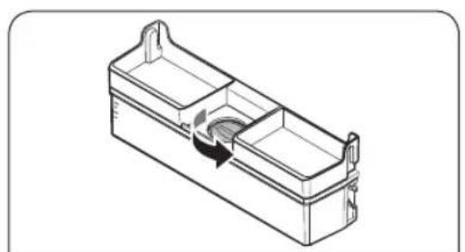
- Fill the water tank with potable water up to 3.5 liters (MAX). You can remove either the top cap or the cover and pour water.

CAUTION
- The water dispenser is designed to dispense potable water. Fill the water tank only with potable water. Do not fill with any other liquids.
- Do not fill the water tank excessively, which causes an overflow.
NOTE
For first-time use, clean inside the water tank.
Operations

- Reinsert the water tank and close the door. Make sure the water outlet of the water tank faces forward.

- Place a water glass under the dispenser's water outlet and gently push the dispenser lever to dispense water. Ensure the water dispenser is unlocked.
CAUTION
- Do not store items on top of the water tank cap.
- Do not attempt to fill the water tank without removing it from the door. • Make sure the water tank is seated properly.
- Do not use the refrigerator without the water tank. This may reduce performance and efficiency. • To prevent water splashing, ensure the glass is aligned with the dispenser lever.
NOTE
To create more space, you can use the water tank to store food. In this case, remove the lid of the tank.
Optimal Fresh+ (applicable models only)

The Optimal Fresh+ drawer allows you to divide the area into two separate zones using the Flex Divider.
Store meat and fish on the left side of Optimal Fresh+ and vegetables and fruits on the right side.

Removing the Flex Divider
While pressing the rear side, pull up the front side to remove it.
Humidity Fresh+ (applicable models only)

Humidity Fresh+ allows you to adjust the humidity. Turn the control dial left or right to adjust the humidity as desired.
Operations
Using the freezer shelf (applicable models only)

To get more space, you can remove all the drawers and locate the 'Freezer Shelf' on the bottom drawer, since it does not affect thermal and mechanical characteristics.
A declared storage volume of frozen food storage compartment is calculated with these drawers removed.
(In the case of Singapore model, declared volume is calculated with taking out the upper & middle drawer only.)

- Remove the tape attached on the shelf.

- Take out all the drawers to assemble the shelf.
- Insert the freezer shelf with the "Front" mark side up. If the "Front" mark is unable to identify, insert the protruding part of the shelf at first as shown in figure.
CAUTION
- Do not insert the shelf upside-down, or in the reverse direction.
- When you don't use the freezer shelf, keep it safe for later use.
NOTE
When storage the glass container on the tempered shelf, the scratch may occur since friction on the shelf.
Maintenance
Reversing the door handle position (For models with bar handles)
NOTE
This procedure applies to both the fridge and freezer compartment.

- Use a flat-head screwdriver to remove the screw covers.
- After detaching the handle, attach the screw covers back on the screw holes.

- Use a Phillips screwdriver to remove the screws and detach the handle.
NOTE
Use these screws to fasten the handle on the opposite side.

- On the opposite side of the door, use a flat-head screwdriver to remove the screw covers.

- Place the handle on the opposite side of the door and use a Phillips screwdriver to attach the handle with the screws.
Maintenance

- Attach the screw covers.
Door reversal (applicable models only)
WARNING
- Tilting/laying the refrigerator requires a minimum of 2 people.
- Disconnect the power cord before reversing the doors.
Tools required (not provided)

Philips screwdriver Flat-head screwdriver 11 mm spanner

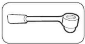

10 mm socket wrench 8 mm socket wrench 10 mm spanner
English42-
Accessories


Top-left hinge cover Top-right door cover (applicable models only)
CAUTION
- Be careful not to damage the wires and connectors during this process.
- Throughout the entire reversing procedure, keep all the small parts (screws, caps, etc.) of the refrigerator away from children or infants for safety reasons.
- Make sure to keep all the screws and other removed parts in a safe place during the door reversal process.
NOTE
- Samsung recommends that reversing of the door opening is only completed by Samsung approved service providers. This will be on a chargeable basis at the customer's expense.
- Before reversing the doors, put a protective material (such as a cardboard box) on the floor where you can safely place the removed parts, preventing any damage throughout the whole process.
Reversing the door
NOTE
For the models with handles, reverse the handles first. (For detailed information, see the "Reversing the door handle position (For models with bar handles)" section.)

- With the fridge door closed, use a Phillips screwdriver to remove the screws fastening the top cover (A).
Maintenance
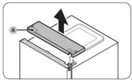


- Gently lift the top cover (A) and place it on top of the refrigerator.
- Be careful when you lift the top cover (A). There is a wire connected underneath it.
- Remove the wire and the wire connector placed on the holder underneath the top cover.
- This step may not apply to some models.
CAUTION
Do not pull the connectors too hard.
- Disconnect the wire connector (A).
- This step may not apply to some models.
- Use a socket wrench (8 mm) to remove the screws fastening the top hinge (A).
CAUTION
To prevent the fridge door from falling, make sure to hold it tight while removing the screws.
NOTE
You can also use a Phillips screwdriver to remove the screws.


- Open the fridge door, and then lift the door to remove it from the middle hinge. Keep the door in a safe place.

CAUTION
The door is heavy. To prevent damage or injury, use caution while removing the door.
- Open the freezer door, and then use a Phillips screwdriver to remove the screws fastening the bottom hinge (A).
- With the freezer door sitting on the bottom hinge (A), slowly pull the bottom hinge (A) to remove it from the holder on the bottom of the refrigerator. Once the bottom hinge (A) is removed from the holder, remove it from the freezer door, and then pull the freezer door down to remove it from the middle hinge (B).

CAUTION
To prevent the freezer door from falling, make sure to hold the freezer door tight until it is safely removed from the middle hinge (B).
Maintenance

- Use a Phillips screwdriver and socket wrench (10 mm) to remove the screws fastening the middle hinge (A).
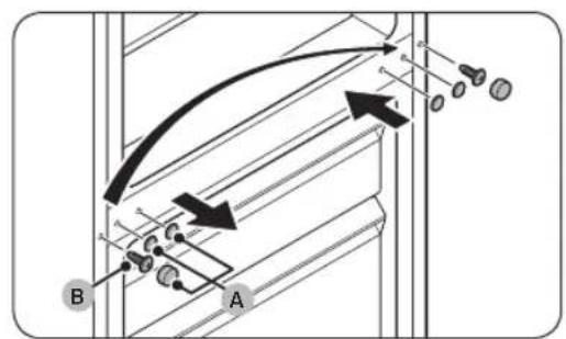
- Remove the middle hinge screw covers (A), and then use a Phillips screwdriver to remove the screw (B).
- On the opposite side, use a Phillips screwdriver to fasten the screw (B), and then put on the middle hinge screw covers (A).

- Remove the bottom hinge screw cover (A) and put it on the opposite side.

- On the bottom of the freezer door, remove the door stopper (A) and put it on the opposite side of the door.
- Use a Phillips screwdriver to remove and tighten the screw fastening the door stopper (A).
- Flip the door stopper (A) before putting it on the opposite side.
![graph TD A["Point A"] --> B["Point B"] style A fill:#f9f,stroke:#333 style B fill:#ccf,stroke:#333](/content/2026/06/1345393/images/cc04e28b2e6c9c5994bf73d0920f40a3c10f058e033b14fbf940d1f75c5fbb59.jpg)

![graph TD A["A"] --> F["F"] F --> C["C"] C --> E["E"] E --> D["D"] D --> B["B"] B --> A style A fill:#f9f,stroke:#333 style B fill:#f9f,stroke:#333 style C fill:#ccf,stroke:#333 style D fill:#ccf,stroke:#333 style E fill:#cfc,stroke:#333 style F fill:#ffc,stroke:#333 style G fill:#cfc,stroke:#333 sty…](/content/2026/06/1345393/images/0ae98c46eb40871cb478949eb5c46ffff1c65e70f6402c273e788f4c7c52b8cd.jpg)
- On the top of the freezer door, switch the position of the grommet (A) and the grommet cover (B).
- Fasten the middle hinge (A) to the opposite side of where it was removed.
- Use a Phillips screwdriver and socket wrench (10 mm) to fasten the screws.
- Disassemble the bottom hinge and reverse all the parts.
a. Use a Phillips screwdriver to remove the screw (A) fastening the fixer (B) to the bottom hinge (C).
b. Use a spanner (10 mm) to remove the nut (D) and washer (E) fastening the shaft (F).
c. Flip the bottom hinge (C), and then reattach the shaft (F) with the washer (E) and the nut (D).
d. Fasten the fixer (B) with the screw (A).
CAUTION
- Be careful not to drop the shaft (F) or hurt your fingers when removing or assembling the shaft (F).
- Make sure the washer (E) is in the correct place. If the shaft is fastened without the washer (E), the freezer door may fall and cause injury.
Maintenance
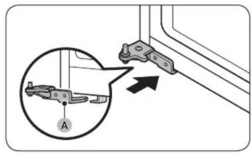


- Turn the levelling leg on the opposite side of where bottom hinge (A) was removed. Then, put the bottom hinge (A) on the holder.
- Attach the freezer door.
a. Put the freezer door on the bottom hinge (A). Place the door perpendicular to the refrigerator's main body. b. Push the freezer door down to insert the middle hinge (B) into the grommet (C) on top of the freezer door.
CAUTION
Do not push the door too hard. Make sure the bottom hinge (A) stays on the holder at the bottom of the refrigerator throughout this step.
NOTE
After attaching the freezer door, adjust the levelling legs to level the refrigerator. (For detailed instruction, see the "STEP 4 Adjust the levelling legs" section on page 32.)
- Use a Phillips screwdriver to fasten the bottom hinge (A) with the screws. Then, close the freezer door.


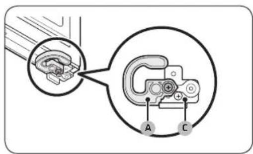
- On the bottom of the fridge door, remove all the parts on the left and right side.
a. Use a Phillips screwdriver to remove the screws. b. Remove the auto closer (A), grommet (B), and door stopper (C) on one side, and the bottom fridge door cover (D) on the other side.
- Switch the sides of all the removed parts.
a. Put the door stopper (C), grommet (B), auto closer (A) on the opposite side to where they were removed. b. Fasten the door stopper (C) and auto closer (A) with the screws using a Phillips screwdriver. c. Put the bottom fridge door cover (D) on the opposite side to where it was removed. d. Fasten the bottom fridge door cover (D) with the screw using a Phillips screwdriver.
CAUTION
You must fasten the screws for the door stopper (C) and auto closer (A) correctly as shown in the figure. If you fasten the screws incorrectly, it causes the door hinge damage.
Maintenance


- On the top of the fridge door, remove the wire cover (A).
- Gently lift either side of the wire cover (A) and pull to remove it from the door.
- This step may not apply to some models.
- Remove the top-right hinge cover (A) and the top-left door cover (B).
This step may not apply to some models.
NOTE
Keep the removed parts in a safe place for later use.
- Remove the top hinge (A) from the fridge door.
- Remove the grommet (A) and put it on the opposite side.
![graph TD A["Device A"] -->|Downward Arrow| B["Device B"] B -->|Upward Arrow| A C["Device C"] -->|Rightward Arrow| B style A fill:#f9f,stroke:#333 style B fill:#bbf,stroke:#333](/content/2026/06/1345393/images/04cf74c24d380de511af124376806ba2cdb90ee0e5198c9c9e5161db8518b3d0.jpg)


- Reverse the top hinge.
a. Use a spanner (11 mm) to disassemble the shaft (A) and washer (B). b. Flip the top hinge (C), and then reattach the washer (B) and shaft (A).

CAUTION
- Be careful not to drop the shaft (A) or hurt your fingers when removing or assembling the shaft (A).
- Make sure the washer (B) is in the correct place. If the shaft is fastened without the washer (B), the door may fall and cause injury.
- Put the fridge door on the middle hinge (A).

CAUTION
To prevent the fridge door from falling, make sure to hold it tight until the top hinge is fastened.
- Put the top hinge (A) on the opposite side to where it was removed.
Maintenance

- Fasten the top hinge (A) with the screws using a socket wrench (8 mm).

- Remove the space cover (A) from the top cover (B) and then put it on the opposite side.

- Underneath the top cover, pull the wire connector (A) from the holders, and move it to the holders on the opposite side.
- This step may not apply to some models.

- Move the wire connector (A) on the fridge door to the opposite side.
- This step may not apply to some models.


- Reconnect the wire connector (A).
- This step may not apply to some models.

CAUTION
Make sure the wire connectors are connected properly. Otherwise, the display does not operate.
- Place the wire and the wire connector (A) on the holder underneath the top cover.
- This step may not apply to some models.
- Attach the provided top-left hinge cover (A) to the top hinge and assemble the top cover (B).
- Place the wires and connectors into the top-left hinge cover (A) and top cover (B). (Some models do not have wires on the fridge door and this may not apply to those models.)
- With the fridge door closed, put the top cover (A) back and fasten it with the screws using a Phillips screwdriver.

CAUTION
Be careful not to damage the wires when fastening the top cover (A).
Maintenance

- Put the provided top-right door cover (A) on the opposite side of the door hinge.
- This step may not apply to some models.

- Place the wire from the fridge door into the space underneath the wire cover (A).
- This step may not apply to some models.

- Put the wire cover (A) back onto the fridge door.
- This step may not apply to some models.
- Open and close the fridge door a few times to check for any problems.

- Detach the fridge and the freezer door gaskets, and then attach them after rotating them 180 degrees.

CAUTION
Make sure the door gaskets are properly attached. If not, there can be a noise or dew can be formed which affects performance of the unit.

NOTE
- After reversing the door, adjust the levelling legs to level the refrigerator. (For detailed instruction, see the "STEP 4 Adjust the levelling legs" section on page 32.)
- To return the door to its initial position, follow the steps again. Please note that the door, hinges, and other parts would then be in the opposite orientation as listed in these steps.
Maintenance
Handle and care
Shelves / Rack & Shelf (applicable models only)

- Pull out the shelf (or Rack & Shelf) a little. Then, while lifting the rear side, pull out.

- Twist the shelf (or Rack & Shelf) diagonally to remove.
English 56-
Foldable shelf (applicable models only)

- Slide the front half of the shelf.

- Pull out the foldable shelf a little. Then, while lifting the rear side, pull out.
- Twist the shelf diagonally to remove.


CAUTION
- Do not put food or objects in front of the Optimal Fresh+. The door may not close properly, and the items may fall down on the floor.
- The shelf must be inserted correctly. Do not insert upside down.
- When reinserting the shelf, make sure to push in the shelf to the end until it fits.
- Glass containers may scratch the surface of glass shelves.
Maintenance
Cleaning
Interior and exterior
WARNING
- Do not use benzene, thinner, or home/car detergent such as Clorox™ for cleaning purposes. They may damage the surface of the refrigerator and cause a fire.
- Do not spray water onto the refrigerator. This may cause electric shock.
Regularly use a dry cloth to remove all foreign substances such as dust or water from the power plug terminals and contact points.
- Unplug the power cord.
- Use a moistened, soft, lint-free cloth or paper towel to clean the refrigerator's interior and exterior.
- When done, use a dry cloth or paper towel to dry well.
- Plug in the power cord.
Real panel / Compressor cover (applicable models only)

To keep cords and exposed parts of the rear panel free of dirt, vacuum the panel once or twice a year.
CAUTION
Do not remove the rear panel cover. Electric shock may occur.
English
Replacement
LED Lamps
To replace the lamps of the refrigerator, contact a local Samsung service centre.

WARNING
- The lamps are not user-serviceable. Do not attempt to replace a lamp yourself. This can cause electric shock.
Lamp (Light Source)
This product contains a light source of energy efficiency class .
The lamp(s) and/or control gear(s) are not user-serviceable. To replace the lamp(s) and/or control gear(s) in the product, contact a local Samsung service centre.
For detailed instructions on replacing lamp(s) or control gear(s) in your product, visit the Samsung website (http://www.samsung.com), go to Support > Support home, and then enter the model name.
For detailed instructions on dismantling lamp(s) and/or control gear(s), simply follow the replacement instruction reached as described above.
Door panel (applicable models only)
You can select the door panel you prefer for your BESPOKE refrigerator. Purchase the door panel at a Samsung retail store and an authorized installer will install the panel for you.

CAUTION
- Disassembling or assembling the door panel on your own may result in product damage or personal injury. If you find any problems with the door panel, contact a Samsung service center
- A service fee may be charged for panel replacement even within the warranty period.
Maintenance
Pair installation (applicable models only)

You can install this refrigerator side by side with another Samsung refrigerator if you want. However, the refrigerators must be the BESPOKE models. If you want the pair installation, check if the desired models allow pair installation before purchasing them. You can check it at the retail store or Samsung.com website.
NOTE
• Purchase the pair installation kit at a Samsung retail store and you can request an authorized installer for pair installation. - Make sure to purchase the appropriate pair installation kit for your model. You must use the dedicated pair installation kit to prevent any installation problem.
- RB34 model: RA-C00K4BAA
- RB38 model: RA-C00K3BAA
- Pair installation may increase energy consumption.

| 01 more than 50 mm recommended |
| 02 105° |
| 03 1250 mm |
| 04 1212 mm |
| 05 Upper bracket |
| 06 Trim |
| 07 Install direction |
Tools required (not provided)


Phillips screwdriver Flat-head screwdriver 8 mm socket wrench (for
bolts)
Pair installation kit accessories

A. Upper bracket (1)

B. Lower bracket (1)

C. Trim (1) D. A/S Jig-sheet ref (4)


E. Level adjustment pad (4)

F. T7 LEX foam (8) G. T5 PE foam (1) H. Rear bracket (1)


J. M5 x 16 hex screws (4)

K. M4 x 18 screws (2)
NOTE
- The number in parenthesis refers to the quantity of each accessory.
- Lower bracket (B) and Trim (C) come in two sizes (7 or 15 mm). Check the sizes when you order the pair installation kit.
Maintenance
Step-by-step instruction
NOTE
The alphabet letters on the figure and in the parenthesis are the same as those in the accessories list.

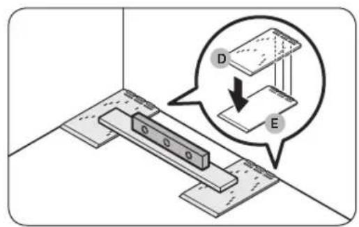

- Check the level of the floor.
- Use a level to check the level of the floor where the refrigerator's two rear casters will be placed.
- Place the A/S jig-sheet refs (D) and check the level.
Place the two provided A/S jig-sheet refs (D) on the floor where the refrigerator's two rear casters will be placed, and then check the level.
If the floor is not level, put the provided level adjustment pads (E) under the A/S jig-sheet refs (D) so the refrigerator will stand on a level surface.
Once you sort out all the necessary parts to level, peel off the double-sided tape on the bottom of each part and attach the part in its final position.


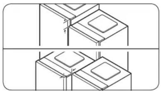
- Attach the foams to maintain a gap between the two refrigerators.
NOTE
You must attach the T5 PE foam (G) to the BMF (Bottom-mounted freezer) model only. (In case you install two different types of refrigerators in pair.)
A. Pair install of RB38 model:
Attach the T5 PE foam (G).
See the figure for the position of the foam.
B. Pair install of RB34 model:
Attach the T5 PE foam (G), and then attach four T7 LEX foams (F) on top of the T5 PE foam (G).
See the figure for the position of the foams.
- Align the two refrigerators.
- Check the alignment at the top and front of the refrigerators and realign them if necessary.
Maintenance


- Remove the screws from the two holes where the lower bracket will be fastened to.
- Open the door of the refrigerators to be paired, and then remove the screws located where the lower bracket will be fastened.
- Fasten the lower bracket (B).
- Fasten the lower bracket (B) with the two M4 x 18 screws (K) (one fastened to each refrigerator) to secure the lower parts of the refrigerators.


- Fasten the upper bracket (A).
- Fasten the upper bracket (A) with the four M5 x 16 hex screws (J) to secure the top part of the refrigerators.
NOTE
Align the tops of the refrigerators before fastening the upper bracket.
- Remove the screws at the back of the refrigerators.
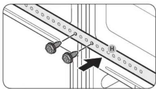
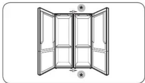
(*): 15 mm (RB34) / 7 mm (RB38)
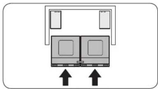

- Use the screws removed from step 8 to fasten the rear bracket (H).
- Check the spacing between the refrigerators.
- After fastening the upper and lower brackets, make sure the spacing between the refrigerators is 7 or 15 mm at the top and bottom.
NOTE
If the spacing between the refrigerators is greater than 7 or 15 mm, there may be less room between the refrigerator and the walls (or cabinets), and this may interfere when opening the doors.
- Push the refrigerators into the walls (or cabinets).
- Have two people simultaneously push the refrigerators, fixed with brackets, into the walls (or cabinets).
NOTE
If the two people do not push the refrigerators evenly, the rear parts of the refrigerators may spread out or may deviate from their intended spot.
- Adjust the height of the refrigerators.
- Turn the leveling leg right or left to adjust the height of the refrigerators to be flush with the walls (or cabinets).
Maintenance


- Insert the trim (C) between the refrigerators.
- Open the doors and insert the trim (C) between the refrigerators.
NOTE
See the enlarged part of the trim in the figure to identify the trim's top side.
- Do a final check.
- If there are no problems, peel all the protective film off the product.
Troubleshooting
Before calling for service, review the checkpoints below. Any service calls regarding normal situations (No Defect Cases) will be charged to users.
General
Temperature
| Symptom Possible causes Solution | ||
| Fridge/freezer does not operate.Fridge/freezer temperature is warm. | Power cord is not plugged in properly.Temperature control is not set correctly.Refrigerator is located near a heat source or direct sunlight.Not enough clearance between refrigerator and sides/rear.The Vacation function is activated.The refrigerator is overloaded. Food is blocking the refrigerator vents. | Properly plug in the power cord.Set the temperature lower.Keep the refrigerator away from direct sunlight or a heat source.Make sure there are at least 5 cm from the rear and sides.Deactivate the Vacation function.Do not overload the refrigerator. Do not allow food to block ventilation. |
| Fridge/freezer is over-cooling. | Temperature control is not set correctly. | Set the temperature higher. |
| Interior wall is hot. | Refrigerator has heat-proof piping in the interior wall. | To prevent condensation from forming, the refrigerator has heat-proof piping in the front corners. If the ambient temperature rises, this equipment may not work effectively. This is not a system failure. |
Troubleshooting
Odours
| Symptom Possible causes Solution | ||
| Refrigerator has odours. | • Spoiled food. | • Clean the refrigerator and remove any spoiled food. |
| • Food with strong odours. | • Make sure strong smelling food is wrapped airtight. | |
Frost
| Symptom Possible causes Solution | ||
| Frost around the vents. | ·Food is blocking the vents. | ·Make sure no food blocks the refrigerator vents. |
| Frost on interior walls. | ·Door is not closed properly. | ·Make sure food does not block the door. Clean the door gasket. |
Excessive frost build-ups in the freezer. | ·The door is not sealing properly because the door gasket was not reversed after reversing the doors. | ·Detach the door gasket and then attach it after rotating it 180°. |
Condensation
| Symptom Possible causes Solution | ||
| Condensation forms on the interior walls. | ·If door is left open, moisture enters the refrigerator. | ·Remove the moisture and do not open the door for a long time. |
| ·Food with high moisture content. | ·Make sure food is wrapped airtight. | |
Do you hear abnormal sounds from the refrigerator?
Before calling for service, review the checkpoints below. Any service calls related to normal sounds will be charged to the user.
These sounds are normal.
- When starting or ending an operation, the refrigerator may make sounds similar to a car engine igniting. As the operation stabilizes, the sounds will decrease.
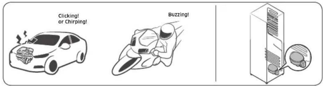
- While the fan is operating, these sounds may occur. When the refrigerator reaches the set temperature, no fan sound will occur.

- During a defrost cycle, water may drip on the defrost heater, causing sizzling sounds.

Troubleshooting
- As the refrigerator cools or freezes, refrigerant gas moves through sealed pipes, causing bubbling sounds.

- As the refrigerator temperature increases or decreases, plastic parts contract and expand, creating knocking noises. These noises occur during the defrosting cycle or when electronic parts are working.

- For ice maker models: When the water valve opens to fill the ice maker, buzzing sounds may occur.
- Due to pressure equalizing when opening and closing the refrigerator door, whooshing sounds may occur.
Appendix
Safety Instruction
- For the most efficient use of energy, please keep all inner fittings such as baskets, drawers, shelves, and ice cube tray in the position supplied by the manufacturer.
- This refrigerating appliance is not intended to be used as a built-in appliance.
Installation Instruction
For refrigerating appliances with climate class
Depending on the climate class, this refrigerating appliance is intended to be used at ambient temperatures within the range specified in the following table.
The climate class can be found on the rating plate. The product may not operate properly at temperatures outside of the specific range.
You can find the climate class on the label inside your refrigerator.
Effective temperature range
The refrigerator is designed to operate normally within the temperature range specified by its class rating.
| Class Symbol | Ambient Temperature range (°C) | ||
| IEC 62552 (ISO 15502) ISO 8561 | |||
| Extended Temperate SN +10 to +32 | +10 to +32 | ||
| Temperate N +16 to +32 +16 | to +32 | ||
| Subtropical ST +16 to +38 +18 | to +38 | ||
| Tropical T +16 to +43 +18 to | +43 | ||
NOTE
The cooling performance and power consumption of the refrigerator may be affected by the ambient temperature, the frequency of door openings, and the location of the refrigerator. We recommend adjusting the temperature settings as appropriate.
Appendix
Temperature Instruction
Recommended Temperature
The optimal temperature settings for food storage:
- Fridge: 3 °C
- Freezer: -19 °C
NOTE
The optimal temperature setting of each compartment depends on the ambient temperature. The optimal temperature is based on an ambient temperature of 25°C.
Power Cool
Power Cool speeds up the cooling process at maximum fan speed. The fridge keeps running at full speed for two and a half hours and then returns to the previous temperature.
Power Freeze
Power Freeze speeds up the freezing process at maximum fan speed. The freezer keeps running at full speed for 50 hours and then returns to the previous temperature. To freeze large amounts of food, activate Power Freeze for at least 20 hours before putting food in the freezer.
NOTE
When you use this function, the energy consumption of the refrigerator will increase. Remember to turn it off when you don't need it and return the freezer to your original temperature setting.
How to store for best preservation (applicable models only)
Cover foods to retain moisture and prevent them from picking up odors from other foods. A large pot of food like soup or stew should be divided into small portions and put in shallow containers before being refrigerated. A large cut of meat or whole poultry should be divided into smaller pieces or placed in shallow containers before refrigerating.
Placement of Foods
| Shelves | Shelves should be adjustable to accommodate a variety of packages. |
| Specialized compartment (applicable models only) | Sealed crisper drawers provide an optimal storage environment for fruits and vegetables. Vegetables require higher humidity conditions while fruits require lower humidity conditions.Crispers are equipped with controls devices to control the humidity level. (*Depending on model and options) An adjustable temperature meat drawer maximizes the storage time of meats and cheeses. |
| Stored on the door | Don’t store perishable foods in the door. Eggs should be stored in the carton on a shelf. The temperature of the storage bins in the door fluctuate more than the temperature in the cabinet. Keep the door closed as much as possible. |
| Freezer Compartment | You can store frozen food, make ice cubes and freeze fresh food in the freezer compartment. |

NOTE
Freeze fresh, undamaged food only. Keep food which is to be frozen away from food which is already frozen. To prevent food from losing its flavor or drying out, place in airtight containers.
Refrigerator & Freezer Storage Chart
The freshness longevity depends on temperature and exposure to moisture. Since product dates aren't a guide for safe use of a product, consult this chart and follow these tips.
Milk products
| Product Refrigerator | Freezer | |
| Milk 1 week 1 month | ||
| Butter 2 weeks 12 months | ||
| Ice cream - 2-3 weeks | ||
| Natural cheese 1 month 4-6 months | ||
| Cream cheese 2 weeks Not recommended | ||
| Yogurt 1 month | - |
Meat
| Product Refrigerator | Freezer | |
| Fresh roasts, steaks, chops | 3-4 days | 2-3 months |
| Fresh ground meat, stew meat | 1-2 days | 3-4 months |
| Bacon | 7 days | 1 month |
| Sausage, Raw from pork, beef, turkey | 1-2 days | 1-2 months |
Appendix
Poultry / Eggs
| Product Refrigerator Freezer | |
| Fresh poultry 2 days 6-8 months | |
| Poultry salad 1 day - | |
| Eggs, Fresh in shell 2-4 weeks | Not recommended |
Fish / Seafood
| Product Refrigerator | Freezer | |
| Fresh fish 1-2 days 3-6 months | ||
| Cooked fish 3-4 days 1 month | ||
| Fish salad 1 day Not recommended | ||
| Dried or pickled fish | 3-4 weeks | - |
Fruits
| Product Refrigerator Freezer | ||
| Apples | 1 month | - |
| Peaches | 2-3 weeks | - |
| Pineapple | 1 week | - |
| Other fresh fruit | 3-5 days | 9-12 months |
Vegetables
| Product Refrigerator Freezer | ||
| Asparagus | 2-3 days | - |
| Broccoli, Brussels sprouts, green peas, mushrooms | 3-5 days | - |
| Cabbage, cauliflower, celery, cucumbers, lettuce | 1 week | - |
| Carrots, beets, radishes | 2 weeks | - |
English74
Information for model and ordering spare parts
Model information
To access the EPREL registration of the model:
- Go to https://eprel.ec.europa.eu
- Get the model identifier from the energy label of the product and type it in the search box
- Energy Labelling information of the model is shown
Part information
- The minimum period during which spare parts, necessary for the repair of the appliance, are available
- 7 Years thermostats, temperature sensors, printed circuit boards and light sources, door handles, door hinges, trays, baskets (boxes or drawers)
- 10 Years door gaskets
- The minimum duration of the guarantee of the refrigerating appliance offered by the manufacturer 24 Months.
- Relevant information for ordering spare parts, directly or through other channels provided by the manufacturer, importer or authorized representative
- You can find professional repair information on http://samsung.com/support. You can find user servicing manual on http://samsung.com/support.
SAMSUNG
Contact SAMSUNG WORLD WIDE
If you have any questions or comments relating to Samsung products, please contact the SAMSUNG customer care center.
| Country Contact Center Web Site | |
| CROATIA 072 726 786 www.samsung.com/hr/support | |
| BOSNIA 055 233 999 www.samsung.com/ba/support | |
| MONTENEGRO 020 405 888 www.samsung.com/support | |
| SLOVENIA 080 697 267 (brezplačna številka) www.samsung.com/si/support | |
| SERBIA 011 321 6899 www.samsung.com/rs/support | |
| ALBANIA 045 620 202 www.samsung.com/al/support | |


DA68-04111L-04
Refrigerators

SAMSUNG
Contents
Safety information 3


![graph TD A["A"] --> C["C"] B["B"] --> C["C"] C["C"] --> D["D"] D["D"] --> E["E"] E["E"] --> F["F"] F["F"] --> A["A"] style A fill:#f9f,stroke:#333 style B fill:#f9f,stroke:#333 style C fill:#ccf,stroke:#333 style D fill:#ccf,stroke:#333 style E fill:#ccf,stroke:#333 style F fill:#ccf,stroke:#333](/content/2026/06/1345393/images/4200333c94219ad44dceecd63830677e434fe4261b478185597c799397b72432.jpg)


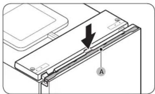


1. Check the leveling of the floor.


(*): 15 mm (RB34) / 7 mm (RB38)


Refrigerator


SAMSUNG
Contents


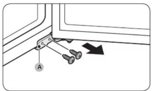

![graph TD A["A"] --> F["F"] F --> C["C"] C --> E["E"] E --> D["D"] D --> B["B"] B --> A style A fill:#f9f,stroke:#333 style B fill:#f9f,stroke:#333 style C fill:#ccf,stroke:#333 style D fill:#ccf,stroke:#333 style E fill:#cfc,stroke:#333 style F fill:#ffc,stroke:#333 style G fill:#cfc,stroke:#333 sty…](/content/2026/06/1345393/images/9b76b3f9fe368e48360eb9ad6ff259b35f7f3ac09300869d02df6e47ac0eae0a.jpg)

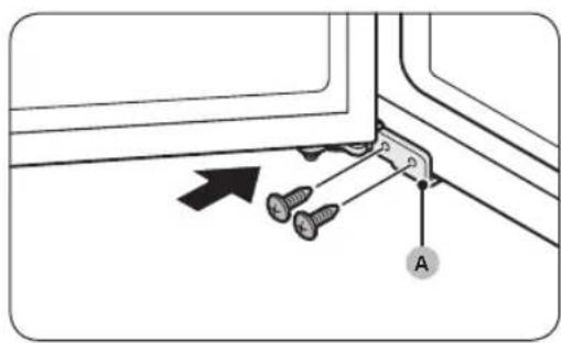

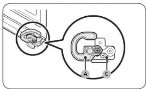


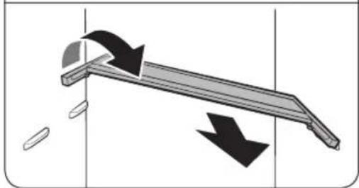


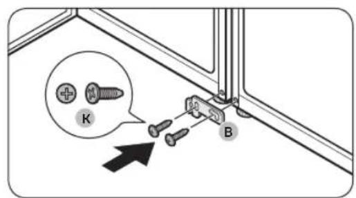


(*): 15 mm (RB34) / 7 mm (RB38)


SAMSUNG
Index
STEP 3 Floor

To adjust the height on the left side:
To adjust the height on the right side:


- Reinsert the water tank and close the door. Make sure the water outlet on the water tank is facing forward.

- Place a glass under the water dispenser outlet and gently press the lever of the filling tank. Make sure the dispenser is unlocked.
CAUTION
The Humidity Fresh+ drawer allows you to set the humidity. Turn the selector knob left or right to set the desired humidity.
Procedures
- Remove the tape attached to the shelf.


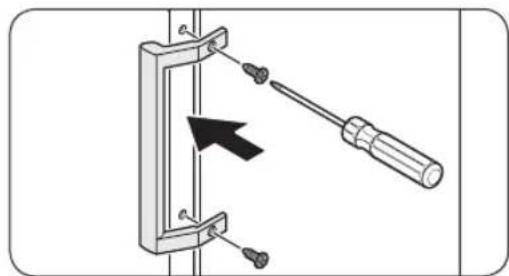
NOTE
- Install the screw caps.


- Gently lift the top cover (A) and place it on the top side of the refrigerator.
- Be careful when lifting the top cover (A). There is a wire connected underneath it.
- Remove the wire and the wire connector located on the holder under the top cover.
- On some models, this step is not necessary.
CAUTION
Do not pull the connectors with excessive force.


- Using a Phillips screwdriver and a socket wrench (10 mm), remove the screws that secure the middle hinge (A).
- Remove the screw caps of the middle hinge (A), then use a Phillips screwdriver to remove the screw (B).
- On the opposite side, tighten screw (B) with a Phillips screwdriver, then install the middle hinge screw caps (A).
- Remove the lower hinge screw cap (A) and place it on the opposite side.
- At the bottom of the freezer door, remove the door stop (A) and install it on the opposite side of the door.
- With a Phillips screwdriver, remove and tighten the screw that secures the door stop (A).
- Turn the door stop (A) before installing it on the opposite side.
Maintenance


![graph TD A["A"] --> F["F"] F --> C["C"] C --> E["E"] E --> D["D"] D --> B["B"] B --> A style A fill:#f9f,stroke:#333 style B fill:#f9f,stroke:#333 style C fill:#ccf,stroke:#333 style D fill:#ccf,stroke:#333 style E fill:#cfc,stroke:#333 style F fill:#ffc,stroke:#333 style G fill:#cfc,stroke:#333 sty…](/content/2026/06/1345393/images/413cd0963c0ae34110abaaa41849a3f49dc29f10cf6625de1724d04134286841.jpg)
- At the top of the freezer door, reposition the rivet (A) and the rivet cover (B).
- Install the middle hinge (A) on the opposite side from which you removed it.
- Tighten the screws with a Phillips screwdriver and a socket wrench (10 mm).
- Disassemble the lower hinge and replace all parts.
a. Remove the screw (A) that secures the mounting bracket (B) to the lower hinge (C) using a Phillips screwdriver. b. Remove the nut (D) and the clamp (E) that secure the shaft (F) using a wrench (10 mm). c. Turn the lower hinge (C) over, then reattach the shaft (F) with the clamp (E) and the nut (D). d. Tighten the mounting bracket (B) with the screw (A).
CAUTION


- Turn the leveling foot to the opposite side from where you removed the lower hinge (A). Then place the lower hinge (A) on the bracket.
- Install the freezer door.


- Secure the upper hinge (A) with the screws and a socket wrench (8 mm).

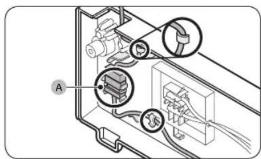


- Reinstall the wire cover (A) on the refrigerator door.
- On some models, this step is not necessary.
- Pull the shelf (or shelf and stand) out slightly. Then lift the rear side and pull it out.
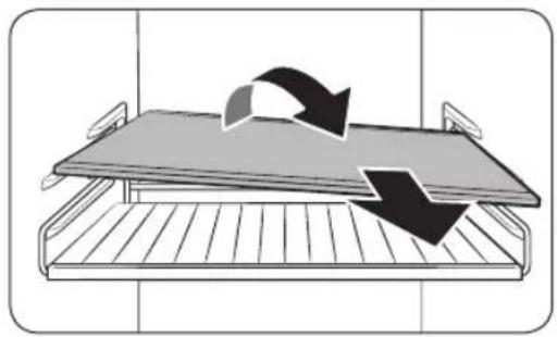
- Turn the shelf (or shelf and stand) sideways and remove it.
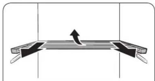


- Slide the upper half of the shelf.
- Pull the foldable shelf out slightly. Then lift the rear side and pull it out.
- Turn the shelf sideways and remove it.
CAUTION
Vacuum the rear panel once or twice a year to keep cables and exposed parts clean.
CAUTION


- Attach the foam pieces to maintain space between the two refrigerators.
NOTE

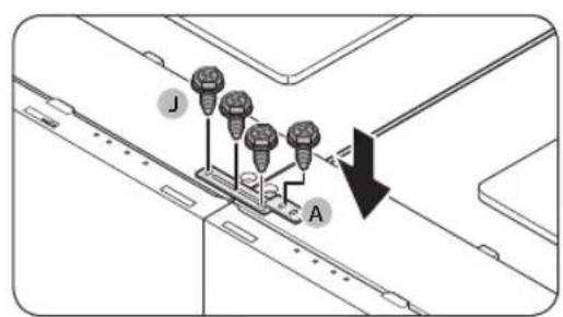


(*): 15 mm (RB34)/7 mm (RB38)


- Insert the trim (C) between the refrigerators.
- Open the doors and insert the trim (C) between the refrigerators.
NOTE
- CONTENTS
- INSTALLATION
- STEP 4 ADJUSTING THE LEVELING LEGS
- CAUTION
- TO ADJUST THE HEIGHT OF THE LEFT SIDE OF THE REFRIGERATOR
- TO ADJUST THE HEIGHT OF THE RIGHT SIDE OF THE REFRIGERATOR
- STEP 5 INITIAL SETTINGS
- HUMIDITY FRESH+ ZONE (CERTAIN MODELS ONLY)
- OPERATIONS
- MAINTENANCE
- REVERSING THE DOOR SWING (CERTAIN MODELS ONLY)
- ⚠ WARNING
- REQUIRED TOOLS (NOT PROVIDED)
- NOTE
- HANDLING AND CARE
- CLEANING
- REPLACEMENT
- LED LAMPS
- WARNING
- LAMP (LIGHT SOURCE)
- CHECK THE FLOOR LEVEL
- PLACE THE A/S TEMPLATES (D) AND CHECK THE LEVEL
- STEP 3 SHELF
- REMOVING THE FLEX SHELF
- HUMIDITY FRESH+ (ON CERTAIN MODELS ONLY)
- INSIDE AND OUTSIDE
- LED BULB
- REFRIGERATOR
- SAFETY INFORMATION
- TROUBLESHOOTING
- APPENDIX
- ENGLISH
- WHAT YOU NEED TO KNOW ABOUT THE SAFETY INSTRUCTIONS
- IMPORTANT SAFETY SYMBOLS AND PRECAUTIONS
- IMPORTANT SAFETY PRECAUTIONS
- HOW TO MINIMIZE ENERGY CONSUMPTION
- THIS APPLIANCE IS INTENDED TO BE USED IN HOUSEHOLD AND SIMILAR APPLICATIONS SUCH AS
- SEVERE WARNING SIGNS FOR TRANSPORTATION AND SITE
- CRITICAL INSTALLATION WARNINGS
- INSTALLATION CAUTIONS
- CRITICAL USAGE WARNINGS
- USAGE CAUTIONS
- CLEANING CAUTIONS
- CRITICAL DISPOSAL WARNINGS
- ADDITIONAL TIPS FOR PROPER USAGE
- INSTRUCTIONS ABOUT THE WEEE
- REFRIGERATOR AT A GLANCE
- STEP-BY-STEP INSTALLATION
- STEP 1 SELECT A SITE
- SITE REQUIREMENTS
- CLEARANCE
- STEP 2 SPACING (APPLICABLE MODELS ONLY)
- STEP 3 FLOORING
- STEP 4 ADJUST THE LEVELLING LEGS
- TO ADJUST THE HEIGHT OF THE LEFT SIDE
- TO ADJUST THE HEIGHT OF THE RIGHT SIDE
- STEP 6 TEMPERATURE ALARM (APPLICABLE MODELS ONLY)
- STEP 7 FINAL CHECK
- CONTROL PANEL
- SETTING THE DESIRED TEMPERATURE OR FUNCTION
- SPECIAL FEATURES
- WATER DISPENSER (APPLICABLE MODELS ONLY)
- OPTIMAL FRESH+ (APPLICABLE MODELS ONLY)
- HUMIDITY FRESH+ (APPLICABLE MODELS ONLY)
- USING THE FREEZER SHELF (APPLICABLE MODELS ONLY)
- REVERSING THE DOOR HANDLE POSITION (FOR MODELS WITH BAR HANDLES)
- DOOR REVERSAL (APPLICABLE MODELS ONLY)
- TOOLS REQUIRED (NOT PROVIDED)
- ACCESSORIES
- REVERSING THE DOOR
- HANDLE AND CARE
- SHELVES / RACK & SHELF (APPLICABLE MODELS ONLY)
- FOLDABLE SHELF (APPLICABLE MODELS ONLY)
- INTERIOR AND EXTERIOR
- DOOR PANEL (APPLICABLE MODELS ONLY)
- PAIR INSTALLATION (APPLICABLE MODELS ONLY)
- PAIR INSTALLATION KIT ACCESSORIES
- STEP-BY-STEP INSTRUCTION
- GENERAL
- DO YOU HEAR ABNORMAL SOUNDS FROM THE REFRIGERATOR
- THESE SOUNDS ARE NORMAL
- SAFETY INSTRUCTION
- INSTALLATION INSTRUCTION
- FOR REFRIGERATING APPLIANCES WITH CLIMATE CLASS
- EFFECTIVE TEMPERATURE RANGE
- TEMPERATURE INSTRUCTION
- RECOMMENDED TEMPERATURE
- POWER COOL
- POWER FREEZE
- HOW TO STORE FOR BEST PRESERVATION (APPLICABLE MODELS ONLY)
- REFRIGERATOR & FREEZER STORAGE CHART
- INFORMATION FOR MODEL AND ORDERING SPARE PARTS
- MODEL INFORMATION
- PART INFORMATION
- SAMSUNG
- CONTACT SAMSUNG WORLD WIDE
- REFRIGERATORS
- CHECK THE LEVELING OF THE FLOOR
- INDEX
- STEP 3 FLOOR
- TO ADJUST THE HEIGHT ON THE LEFT SIDE
- TO ADJUST THE HEIGHT ON THE RIGHT SIDE
- PROCEDURES
Brand : SAMSUNG
Model : RB38T650EB1
Category : Refrigerator