
OfficeConnect M220 - Access Point HP - Free user manual and instructions
Find the device manual for free OfficeConnect M220 HP in PDF.


| Product Type | Wireless Access Point |
| Model | OfficeConnect M220 |
| Brand | HP |
| Dimensions (W x D x H) | Approximately 200 x 200 x 45 mm (7.9 x 7.9 x 1.8 in) |
| Weight | Approximately 0.5 kg (1.1 lb) |
| Power Supply | PoE (Power over Ethernet) IEEE 802.3af/at or 12V DC adapter (not included) |
| Wireless Standards | IEEE 802.11 a/b/g/n/ac, dual-band 2.4 GHz and 5 GHz |
| Maximum Data Rate | Up to 1200 Mbps (2.4 GHz: 300 Mbps; 5 GHz: 867 Mbps) |
| Ethernet Ports | 1 x Gigabit Ethernet (RJ-45) with PoE input |
| Antennas | 2 internal dual-band antennas |
| Management | Web-based GUI, SNMP v1/v2c/v3, CLI (Telnet/SSH), DHCP client |
| Security | WPA/WPA2-PSK, WPA/WPA2-Enterprise, MAC address filtering, VLAN support |
| Mounting | Wall mount and ceiling mount (bracket included) |
| Operating Temperature | 0°C to 40°C (32°F to 104°F) |
| Humidity | 10% to 90% non-condensing |
| LED Indicators | Power, LAN, WLAN, PoE status |
| Compliance | FCC, CE, RoHS |
| Included Accessories | Mounting bracket, screws, anchor plugs, quick start guide |
Frequently Asked Questions - OfficeConnect M220 HP
User questions about OfficeConnect M220 HP
0 question about this device. Answer the ones you know or ask your own.
Ask a new question about this device
Download the instructions for your Access Point in PDF format for free! Find your manual OfficeConnect M220 - HP and take your electronic device back in hand. On this page are published all the documents necessary for the use of your device. OfficeConnect M220 by HP.
USER MANUAL OfficeConnect M220 HP
HP M220 802.11n Access Point Configuration and Administration Guide
HP Part Number: 5998-3140
Published: September 2012
Edition: 1

© Copyright 2012 Hewlett-Packard Development Company, L.P.
The information contained herein is subject to change without notice. The only warranties for HP products and services are set forth in the express warranty statements accompanying such products and services. Nothing herein should be construed as constituting an additional warranty. HP shall not be liable for technical or editorial errors or omissions contained herein.
Acknowledgments
Windows® is a U.S registered trademark of Microsoft Corporation.
Warranty
WARRANTY STATEMENT: See the warranty information sheet provided in the product box and available online.
Contents
1 Deploying the M220 7
2 Using Quick setup 9
Overview....9
Automatically running Quick setup the first time you log in 9
Accessing Quick setup after your first login 12
Quick setup wizard 13
Step 1: Specify access point settings....13
Step 2: Specify access point cluster settings....15
Step 3: Specify wireless network settings....16
Security methods....20
WPA/WPA2 Personal 20
802.1X/Dynamic WEP 21
WPA/WPA2 Enterprise 22
Static WEP 23
Quick setup global settings page 24
System summary 25
3 Managing the M220 27
Configuring web server settings 27
SNMP configuration....28
Supported MIBs....28
System time....29
Set system time 30
Daylight savings 30
4 Working with wireless communities and authentication 31
Overview....31
Configuring global RADIUS servers 31
Managing wireless communities 33
About the default wireless community 33
Wireless community configuration options.... 34
Wireless protection 35
MAC authentication 42
5 Wireless configuration ....45
Wireless coverage 45
Factors limiting wireless coverage 45
Configuring overlapping wireless APs
802.11n best practices
Supporting legacy wireless clients
Channel width
Radio configuration
Country
Basic settings
Advanced radio settings
Detecting Rogue APs
Enabling scanning
Detected and Known AP lists
Working with saved AP lists
Viewing wireless information
Viewing all connected wireless clients
Viewing wireless statistics for the radio
6 Creating WDS links 65
Key concepts....65
Simultaneous AP and WDS support 65
Using the 5 GHz band for WDS links 66
Configuration considerations....66
WDS configuration 67
Sample WDS deployment 69
7 Configuring Ethernet, IP, and VLAN settings....73
Ethernet configuration....73
IPv4 configuration....74
Automatically assigning an IP address (default method) 74
Static IP configuration....74
IPv6 configuration 75
VLAN configuration....76
VLAN assignment via wireless communities 76
VLAN assignment via RADIUS 77
Port statistics 78
8 Clustering multiple M220s 79
Overview 79
Shared settings in a cluster 79
IPv4 and IPv6 clusters 80
Cluster formation 81
Client connections 83
Channel planning 84
Configuration 84
Current channel assignments 85
9 Maintenance 87
Configuration file management 87
Reset 87
Save 87
Restore 88
Reboot 88
Software updates....89
Software information....89
Software upgrade....89
System information....90
10 Tools....91
System log 91
System log configuration....91
Remote syslog configuration 92
Events 93
Email alert 93
General configuration 93
Mail server configuration 95
Message configuration 95
Sending a test message 96
Viewing email alert status 96
Network trace configuration 97
Overview 97
Packet trace configuration 97
Packet file trace 98
Remote packet trace 99
Packet trace status 101
Packet trace file download 102
Ping 103
11 Support and other resources 105
Online Documentation 105
Contacting HP 105
HP Websites 105
Conventions 106
A Resetting to factory defaults 107
Factory reset procedures 107
Using the reset button....107
Using the management tool 107
1 Deploying the M220
In a small office, the M220 can be directly connected to a broadband router (DSL or cable) to provide wireless networking for all employees. In the following scenario, employees can share data and resources with each other and access the Internet at the same time:
![graph LR A["Wireless community\nHigh security wireless network for employees using WPA/WPA2."] --> B["M220"] B --> C["Router with DHCP server"] C --> D["Internet"]](/content/2026/06/1344351/images/6e819c1880c7e74290869ad025966b62bf7fbbd46926ff1caa4b55ef36847c98.jpg)
With its wireless community feature, the M220 can be configured to provide up to eight separate wireless networks (all on the same wireless channel), each with its own configuration settings for security, VLAN support, and more.
![graph TD A["Wireless community 1: High security wireless network (WPA/WPA2) for employees"] --> B["M220"] C["Wireless community 2: Low security wireless network for guests"] --> B B --> D["Switch"] D --> E["VLAN 1: Employees with secure access to all network resources and the Internet"] D --> F["VLA…](/content/2026/06/1344351/images/2e675b8fe74a8c928ffeb2441ef01f990f00233e9723c1bc925c82ab3dbfa505.jpg)
In this scenario, employees connect to wireless community 1, which is protected with WPA/WPA2. All employee traffic exits the M220 on VLAN 1, providing access to private resources on the company network and on the Internet.
Guests connect to wireless community 2, which is protected with WEP. All guest traffic exits the M220 on VLAN 2, providing access only to the Internet.
Note: WEP is available only when the radio mode does not support 802.11n.
For offices that already have a wired networking infrastructure, the M220 is easily integrated to provide wireless networking. It can also be used to extend the reach of the network to areas that are difficult or impossible to reach with traditional cabling.
In the following scenario, M220 #1 provides wireless network services to the employees in the main office, while M220 #2 and M220 #3 use the Wireless Distribution System (WDS) to create a wireless link between the main office network and a small network in a warehouse. WDS eliminates the need to run cabling, allowing for fast and easy deployment.
![graph TD A["File server DHCP server"] --> B["M220 #2"] C["Employee computers"] --> B D["Computer"] --> E["M220 #1"] F["Computer"] --> G["M220 #3"] H["Computer"] --> I["M220 #3"] J["Computer"] --> K["M220 #3"] L["Wireless community"] --> M["M220 #1"] N["WDS Wireless link"] -.-> M O["Wireless communit…](/content/2026/06/1344351/images/84c47aee3b001a7f4dc69058764b237ead4364e05b10b0a4a2abf917a353aeab.jpg)
In the following scenario, three M220s provide distinct employee groups access to the Internet through a router on the network. The M220s are joined in a cluster, which enables them to share a single configuration and to be administered as a single unit. Channel planning may be implemented on the cluster to reduce interference and optimize wireless bandwidth usage.
![graph TD subgraph_EmployeeGroup1["Employee group 1"] A1[" "] -->|Wireless community| B1["M220 #1"] end subgraph_EmployeeGroup2["Employee group 2"] A2[" "] -->|Wireless community| B2["M220 #2"] end subgraph_EmployeeGroup3["Employee group 3"] A3[" "] -->|Wireless community| B3["M220 #3"] end B1 --> C[…](/content/2026/06/1344351/images/231535ec96de4fa8e9c4cd8e35a7ed6c72d036f62b96b96d50d9509d5e719b00.jpg)
2 Using Quick setup
Overview
Quick setup provides an easy way to quickly configure settings on the M220 for several different networking scenarios. Just pick the scenario that most closely resembles your installation and fill in the appropriate fields.
Automatically running Quick setup the first time you log in
The first time you log in to the management tool (see the HP M220 802.11n Access Point Quickstart for first time login procedure), the HP end user license agreement displays. When you accept the agreement, a page displays to enable you to select your country so that wireless radio settings are configured appropriately. Select Save to display the first page in the Quick setup wizard.
This page lets you choose one of five configuration scenarios to use as the basis for your setup, as described in the following sections.
Basic wireless network
Choose this option if you want to create a single wireless network to provide wireless connectivity for your users. This option can be used to connect the M220 directly to a broadband router or to an existing wired network, using static IP, DHCP, or IPv6 addressing.
This scenario supports clustering mode, where multiple APs in the network are deployed and administered as a single entity.
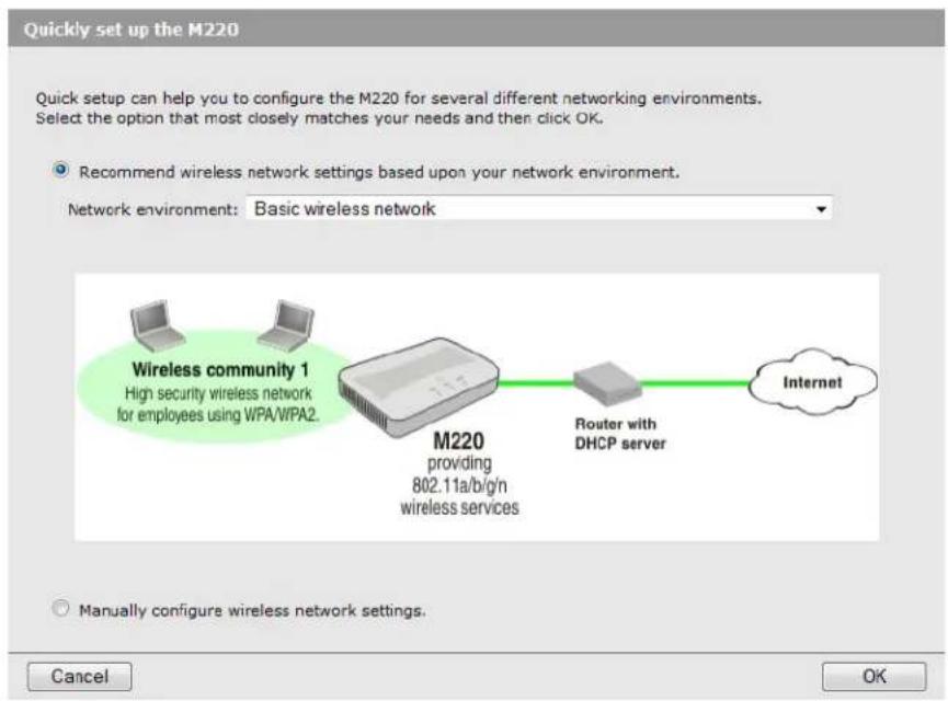
Multiple wireless networks
Choose this option if you want to create multiple wireless networks to support users with different networking requirements. For example, you could create two wireless networks, one for employees and one for guests.
This option can be used to connect the M220 to a network using static IP, DHCP, or IPv6 addressing. This scenario also supports clustering mode, where multiple APs in the network are deployed and administered as a single entity.

Multiple wireless networks with wired VLANs
Choose this option if you want to:
- Create multiple wireless networks to support users with different requirements. Map the traffic from each wireless network to a specific VLAN.
As in Multiple wireless networks mode, this option supports static IP, DHCP, or IPv6 addressing for the network connection, and supports clustering mode.

Multiple wireless networks with RADIUS authentication
Choose this option if you want to:
- Create multiple wireless networks to support users with different requirements.
- Map the traffic from each wireless network to a specific VLAN.
- Authenticate user login credentials using a third-party RADIUS server.
This option can be used to connect the M220 to a network using static IP, DHCP, or IPv6 addressing. This scenario also supports clustering mode, where multiple APs in the network are deployed and administered as a single entity.
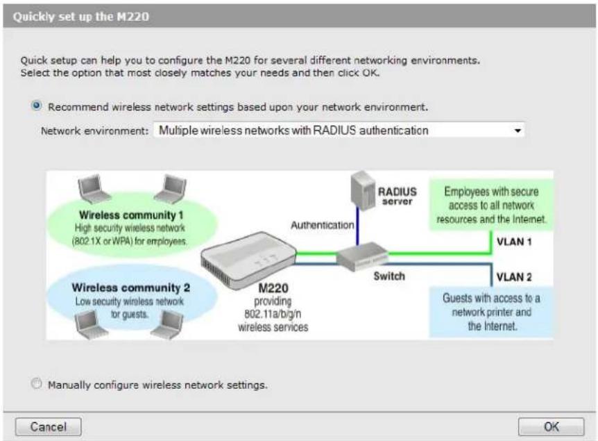
Add to wireless network with existing AP cluster
Use this option if your network already has a defined cluster of M220 APs and you want this AP to join the cluster.

Accessing Quick setup after your first login
When you log in subsequent to completing or cancelling out of the Quick setup wizard, the System summary page displays by default. You can view and configure the Quick setup global settings by selecting Home > Quick setup. See Quick setup global settings page on page 24.
See also the HP M220 802.11n Access Point Quickstart, which describes the configuration procedure for a basic wireless network.
Quick setup wizard
To the Quick setup wizard, select one of the following options for the network environment, as described in the previous sections, and select OK:
- Basic wireless network • Multiple wireless networks • Multiple wireless networks with wired VLANs
- Multiple wireless networks with RADIUS authentication
- Add to wireless network with existing AP cluster
Step 1: Specify access point settings
For a complete description of all settings, see the online help.

Configure the radio
Wireless mode
Select a radio mode.
- IEEE 802.11a: Up to 54 Mbps in the 5 GHz frequency band.
- IEEE 802.11b/g: (Compatibility mode.) Up to 11 Mbps for 802.11b and 54 Mbps for 802.11g in the 2.4 GHz frequency band.
- IEEE 802.11a/n: (Compatibility mode.) Up to 300 Mbps for 802.11n and 54 Mbps for 802.11a in the 5 GHz frequency band.
- IEEE 802.11b/g/n: (Compatibility mode.) Up to 11 Mbps for 802.11b, 54 Mbps for 802.11g, and 300 Mbps for 802.11n in the 2.4 GHz frequency band. If support for 802.11b/g is not required, it is recommended that you choose one of the 802.11n-only modes.
- 5 GHz IEEE 802.11n: (Pure 802.11n) Up to 300 Mbps in the 802.11n 5 GHz frequency band. • 2.4 GHz IEEE 802.11n: (Pure 802.11n) Up to 300 Mbps in the 802.11n 2.4 GHz frequency band.
Get an IP address
You can use these settings to configure IP addresses and how they are assigned. The IPv4 configuration field displays by default. To configure IPv6 settings, click the + to the left of IPv6.
You can configure addresses for both protocol versions. Only IPv4 supports DHCP.
IPv4 addresses
You can select DHCP (the default) so that the IP address will be assigned by a DHCP server on the network. Or, select Static IP to statically configure an address, subnet mask, and default gateway.
IPv6 addresses
You can configure a static IPv6 address and enable autoconfigured IPv6 addressing.
Entering a static IPv6 address
Enter a Static IPv6 address, specify the Static IPv6 address prefix length, and enter the Default IPv6 gateway address.
The Static IPv6 address status shows the configured address. The possible values are as follows:
- Operational: The IP address has been verified as unique on the LAN and is usable on the interface.
- Tentative: The M220 initiates a duplicate address detection (DAD) process automatically when a static IP address is assigned. An IPv6 address is in the tentative state while it is being verified as unique on the network. While in this state, the IPv6 address cannot be used to transmit or receive traffic, except to exchange messages with other network nodes to verify the uniqueness of the address.
- Blank (no value): No IP address is assigned or the assigned address is not operational.
The IPv6 link local address is used by the local physical link. The link local address is not configurable and is assigned by using the IPv6 Neighbor Discovery process.
Enabling auto configuration
When IPv6 auto configuration is enabled, the M220 builds a global IPv6 address by applying an algorithm to the device MAC address and the network prefix that is sent by routers in router advertisements. The autoconfigured addresses display in the IPv6 autoconfigured global addresses list.
Change administrator login credentials
The M220 supports one administrator login. Use this section to change the password.
Note
As an immediate first step in securing your wireless network, it is recommended that you change the administrator password from the default.
Current password
The default password is admin.
New password and Confirm password
Specify a new password for the M220 administrator account.
The administrator password can be from 1 to 32 alphanumeric characters. Do not use special characters or spaces. For security purposes, it is recommended that the password be at least 6 characters.
Caution
If you forget the administrator password, the only way to access the administrator account is to reset the M220 to factory default settings. See Resetting to factory defaults on page 107.
Step 2: Specify access point cluster settings
Use this section to configure whether this AP functions as a member of a cluster of APs on the network. APs in a cluster have a single point of administration, enabling you to view, deploy, configure, and secure the wireless network as a single entity rather than a series of separate wireless devices. When APs are clustered, you can also configure channel planning, which helps to reduce radio interference and maximize bandwidth on the wireless network.
For more information on clustering, see Clustering multiple M220s on page 79.
Step 2: Specify access point cluster settings.
Configure access point clustering.
Clustering:
Cluster name:
Cluster location:
Cluster IP version:

Clustering
Select to enable clustering on this AP.
Cluster name
Specify the name of the cluster to which the AP belongs. The AP will dynamically form a cluster with other APs on the same subnet that have the same cluster name.
Cluster location
Enter a description of the physical location of this AP.
Clustering IP version
Select the IP version that the APs in the cluster use to communicate with each other.
Note
If the selected network environment was Add to wireless network with existing AP cluster, then the Quick setup wizard is complete. Select Save to have the AP join the cluster.
Step 3: Specify wireless network settings
Use this section to define wireless networks and to configure the security settings for client access and encryption.
This section displays different settings depending on the selected network environment.
- For a Basic wireless network, the page displays fields for configuring the network name (SSID) and security settings:
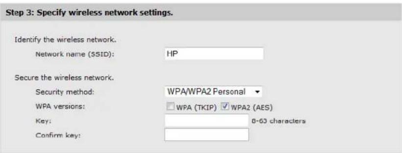
- For a Multiple wireless networks configuration, an additional table displays for adding wireless networks.

- For a Multiple wireless networks with wired VLANs configuration, an additional field displays to enable associating a VLAN with each wireless community:
Step 3: Specify wireless network settings.
- For a Multiple wireless networks with RADIUS authentication configuration, an appropriate security method is selected and additional fields display to configure RADIUS server information:
Step 3: Specify wireless network settings.
- For an Add to wireless network with existing AP cluster configuration, this section does not display, as no security settings or additional wireless communities are needed.
Wireless communities
The M220 allows you to create up to eight wireless communities. Each wireless community defines the settings for a distinct wireless network, with its own network name (SSID), settings for wireless protection, user authentication, VLANs, and more. Radio settings are shared by all wireless communities.
If you selected the Basic wireless network environment, you cannot configure additional wireless communities on the Quick setup page—this configuration assumes that only one wireless network is needed. You can later configure additional communities on the Wireless >Communities page.
A default wireless community is defined on the M220. Its name (or SSID) is HP and it is assigned to VLAN 1. The settings that initially display in the Wireless community settings pertain to the default community.
Note
Before creating a new community, ensure that the name (SSID), VLAN, and security settings for the default community are configured as needed.
To create a new community:
- Select Add New Wireless Community.
An additional row displays in the wireless community table. The fields in the Wireless community settings area display default values for the new community.
- Modify the default values, if necessary. See Wireless community settings for a description of these fields.
- Select Add.
- Select Save to accept the default settings in the Wireless community settings area, or modify the settings and select Add, then Save.
If you select Cancel before selecting Add, the new wireless community will be deleted.
If you change these settings after saving a new wireless community, select Update, then Save. You can select Cancel before selecting Update to undo any changes to these settings.
Wireless community settings
These settings apply to the default wireless community or, if you have created multiple communities, the wireless community selected in the table. After you select Save, you can use the Wireless > Communities page if you want to update these settings.
Identify the wireless network
Use this section to define a name for the wireless community.
Network name (SSID)
Specify a name to uniquely identify the wireless network associated with this community. Each wireless user that wants to connect to this community must use the network name.
By default, the M220 will broadcast this name so that wireless users can see it when they try to connect to the wireless network.
The name is case-sensitive and must include between 2 and 32 alphanumeric characters, including spaces. The following characters are not allowed:
• ?, "", \$, [, ], and + - only spaces - #, !, ; and a space as the first character • a space as the last character
Map wireless network to a VLAN
This option displays only when you select Multiple wireless networks with wired VLANs or Multiple wireless networks with a RADIUS authentication as the network environment. For the other options, all traffic is associated with VLAN 1 by default, and is forwarded untagged to the wired network.
VLAN ID
Enter a VLAN ID to associate it with the wireless community. If this VLAN ID is set to a value other than the management VLAN ID (which is 1 by default), then packets from this wireless community are tagged with the specified VLAN ID when forwarded to the wired network.
The VLAN ID can be from 1 to 4094.
Secure the wireless network
Use this section to define security settings for the wireless network.
Security method
The available security methods and selected default settings vary depending on the selected network environment. The following table lists the security options available with each environment:
You can also disable security on each network environment. However, this is not recommended.
| Network environment Security methods | |
| Basic | If the wireless mode includes 802.11n:WPA/WPA2 Personal (default) |
| Multiple wireless networks | |
| Multiple wireless networks with wired VLANs | If the wireless mode does not include 802.11n:Static WEP (see note)WPA/WPA2 Personal (default) |
| Multiple wireless networks with RADIUS authentication | If the wireless mode includes 802.11n:WPA/WPA2 PersonalWPA/WPA2 Enterprise (default)If the wireless mode does not include 802.11n:Static WEP (see note)802.1X/Dynamic WEP (see note)WPA/WPA2 PersonalWPA/WPA2 Enterprise (default) |
| Add to wireless network with existing AP cluster | The AP will inherit its security settings from the cluster. |
| Note: WEP-based security is not available in 802.11n modes due to Wi-Fi security requirements. | |
The security methods are defined in the following section. After you select a security method and complete the related settings, the Quick setup wizard is complete.
Security methods
A security method (or no security method) can be associated with the default wireless community and any additional communities you create. This section defines the available security methods as they display in the Quick setup wizard. To modify these settings after you complete the Quick setup wizard, or to access additional configuration options, use the Wireless > Communities page.
WPA/WPA2 Personal
WPA Personal provides for secure login using a preshared key (PSK) and for data encryption.
WPA versions
The following WPA versions are supported:
| Version Description |
| WPA WPA with TKIP encryption. |
| Note: If this version is selected and the chosen wireless mode supports 802.11n, then wireless clients that support 802.11n cannot connect at 802.11n transmission rates. They will be connected at legacy rates. If the chosen wireless mode is one of the 802.11n-only modes, then you cannot select this option alone (that is, WPA2 must also be selected). |
| Version Description | |
| WPA2 WPA | 2 (802.11i) with AES-based CCMP encryption. If all of your clients support WPA2, select this option for the maximum possible security. If the chosen wireless mode is one of the 802.11n-only modes, then this mode must be selected. |
| WPA and WPA2 | You can select both versions at the same time. Some legacy WPA clients may not work if this mode is selected. This mode is slightly less secure than using the pure WPA2 mode. |
Key
The M220 uses the key you specify to generate the TKIP or AES keys that are used to encrypt the wireless data stream. Specify a key that is from 8 to 63 alphanumeric characters and re-enter the key in the Confirm key box. It is recommended that the preshared key be at least 20 characters long, and be a mix of letters and numbers. Acceptable characters include upper and lower case alphabetic letters, the numeric digits, and special symbols such as @ and #. The key cannot begin with or end with spaces and cannot contain only spaces.
802.1X/Dynamic WEP
Dynamic WEP uses 802.1X to distribute dynamically generated keys from the AP to its clients, providing better security than Static WEP. A RADIUS server provides a WEP key for each client session and regenerates keys at each reauthentication interval.

RADIUS IP address type
Select an IP version for communicating with the RADIUS server.
RADIUS IP or IPv6 address
Enter the IPv4 or IPv6 address for the primary RADIUS server for this wireless community.
If IPv4 is selected as the RADIUS IP address type, enter the IP address of the RADIUS server that all wireless communities use by default, for example 192.168.10.23. If IPv6 is selected, enter the IPv6 address of the RADIUS server, for example 2001:0db8:1234::abcd.
Note
You can configure only one RADIUS server using the Quick setup wizard. You can, however, configure additional RADIUS servers using the Wireless > Communities page.
RADIUS key
Enter the RADIUS key in the text box.
The RADIUS key is the shared secret key for the global RADIUS server. You can use up to 63 alphanumeric and special characters. The key is case-sensitive and cannot be all spaces. You must configure the same key on the AP and on your RADIUS server. The text you enter will be displayed as “*” characters to prevent others from seeing the RADIUS key as you type.
WPA/WPA2 Enterprise
This option is available in the Quick setup wizard only when you select the Multiple wireless networks with RADIUS authentication network environment.
WPA Enterprise with RADIUS is an implementation of the Wi-Fi Alliance IEEE 802.11i standard, which includes the TKIP and CCMP (AES) mechanisms. The Enterprise mode requires the use of a RADIUS server to authenticate users.
This security mode is backwards compatible with wireless clients that support the original WPA.
WPA versions
Select the types of wireless clients you want to support:
- WPA (TKIP). If all wireless clients on the network support the original WPA but none support the newer WPA2, then select WPA. WPA (TKIP) cannot be used when the radio operating mode supports 802.11n only.
- WPA2 (AES). If all wireless clients on the network support WPA2, we suggest using WPA2, which provides the best security per the IEEE 802.11i standard. If the radio mode is set to one of the 802.11n-only modes, WPA2 is the only supported WPA version.
If you have a mix of clients, some of which support WPA2 and others which support only the original WPA, select both WPA and WPA2. This setting enables both WPA and WPA2 wireless clients to associate and authenticate, but uses the more robust WPA2 for clients that support it. This WPA configuration allows more interoperability, at the expense of some security.
RADIUS IP address type
Select an IP version for communicating with the RADIUS server.
RADIUS IP or IPv6 address
Enter the IPv4 or IPv6 address for the primary RADIUS server for this wireless community.
If IPv4 is selected as the RADIUS IP address type, enter the IP address of the RADIUS server that all wireless communities use by default, for example 192.168.10.23. If IPv6 is selected, enter the IPv6 address of the RADIUS server, for example 2001:0db8:1234::abcd.
Note
You can configure only one RADIUS server using the Quick setup wizard. You can, however, configure additional RADIUS servers using the Wireless > Communities page.
RADIUS key
Enter the RADIUS key in the text box.
The RADIUS key is the shared secret key for the RADIUS server. You can use up to 64 alphanumeric and special characters. The key is case-sensitive, and you must configure the same key on the AP and on your RADIUS server. The text you enter will be displayed as “*” characters to prevent others from seeing the RADIUS key as you type.
Static WEP
This is the least secure method of protecting wireless transmissions. WEP is provided so you can support clients that do not support WPA.

Note: WEP cannot be used when the radio operating mode supports 802.11n.
Key length
Select one of the following values as the length of the encryption key:
- 64 bits: The key can be 5 ASCII characters or 10 hexadecimal digits. • 128 bits: The key can be 13 ASCII characters or 26 hexadecimal digits.
When encryption is enabled, wireless clients that do not support encryption cannot communicate with the M220. The same encryption key must be used on the M220 and all wireless clients.
Key type
Select the format used to specify the encryption key:
- ASCII: ASCII keys are much weaker than carefully chosen hexadecimal keys. You can include ASCII characters from 32 to 126, inclusive, in the key. However, note that not all wireless clients support non-alphanumeric characters such as spaces, punctuation, or special symbols in the key.
- Hex: Your keys should only include the following hexadecimal characters: 0-9, a-f, A-F.
Key 1
Enter a key of the specified format and length. The Quick setup wizard allows you to configure one key. You can configure additional keys on the Wireless > Communities page.
Quick setup global settings page
If you manually launch Quick setup by selecting Home > Quick setup, you will see the Quick setup global settings page. This page will also display if you select Manually configure wireless network settings check box on the initial Quick setup page.



This page enables you to configure the same settings as available in the Quick setup wizard. See "Quick setup wizard" on page 13 for instructions. In addition, the Quick setup global settings page enables you to configure the following settings:
System settings
In the Configure system settings area, you can specify information that helps identify the AP:
System name
Specify a name.
System location
Provide a description that identifies where the M220 is physically located.
System contact
Specify a person to contact for administrative purposes.
Multiple RADIUS servers
If you select 802.1X/Dynamic WEP or WPA/WPA2 Enterprise as the Security method, you can configure multiple RADIUS servers on this page (in the Quick setup wizard you can configure only one).
System summary
After you complete the Quick setup wizard, when you log into the management tool again, the System summary page displays.
| System summary | |
| IP address: | 10.213.2.191 |
| Static IPv6 address: | 3f33:b000:0:1::a |
| IPv6 autoconfigured global addresses: | fd8d:3da:cfa3:213:230:abff:fe2a:6bd8 |
| IPv6 link local address: | fe80::230:abff:fe2a:6bd8 |
| MAC address: | 00:90:4C:08:02:00 |
| Software version: | 1.0.0.0-01-0003 |
| Product identifier: | J9799A |
| Hardware version: | 01 |
| Serial number: | CN27FR2001 |
| Device description: | HP M220 802.11n WW Access Point |
This page includes the following information:
IP address
The IP address assigned to the AP. See the Network > IP page to configure IP information.
Static IPv6 address
The IPv6 address assigned to the AP, if one is configured.
IPv6 autoconfigured global addresses
The global IPv6 address, if one or more has been assigned automatically using the network prefix that is sent by routers in router advertisements.
IPv6 link local address
The link local address is derived automatically using the prefix fe80::/64 and the MAC address of the AP.
MAC address
The MAC address of the AP. This is the address by which the AP is known externally to other networks.
This MAC address applies to the Ethernet port on the AP and to the first (default) wireless community, referred to as wlan0. The MAC address is incremented by 1 for each additional wireless community that you create. For example, if the Ethernet and wlan0 interfaces are assigned MAC address 00:55:9A:3C:7A:00, then the next wireless community you create will be assigned MAC address 00:55:9A:3C:7A:01, and so on.
Software version
The version of software installed on the AP.
Product identifier
The AP hardware model ID number.
Hardware version
The AP hardware version.
Serial number
The AP serial number.
Device description
Information about the product hardware.
3 Managing the M220
The M220 is managed via its web-based management tool using Microsoft Internet Explorer 8+ or Mozilla Firefox 9+. You can access the M220 management tool using either http or https. Using https is more secure but you will see a security warning until you purchase and install your own certificate. With https, it is acceptable to choose the option that allows you to proceed through the security warning.
In a web browser, specify either: http://192.168.1.1 or https://192.168.1.1.
For information on launching the management tool for the first time, see the HP M220 802.11n Access Point Quickstart.
Configuring web server settings
Select Management > Management tool to open the Configure web server settings page.
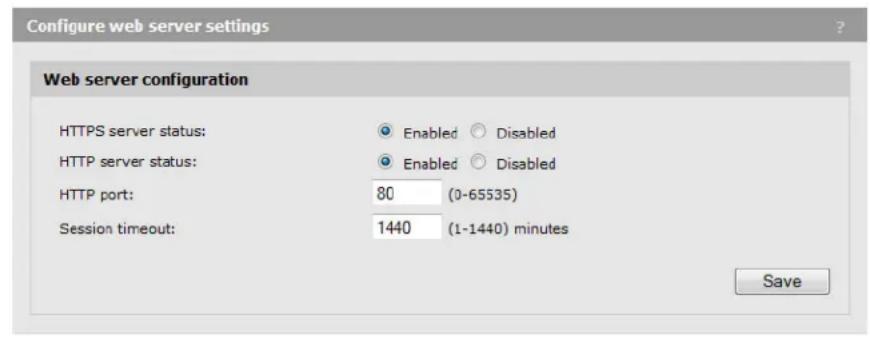
HTTPS server status
HTTP server status
The M220 software includes HTTP and HTTPS functionality to enable communication with your web browser. Unlike HTTP, HTTPS enables secure sessions, using a digital certificate to encrypt data exchanged between the M220 and your web browser. HTTP and HTTPS are both enabled by default.
The M220 supports only one management session at a time via HTTP or HTTPS.
HTTP port
By default, the HTTP server uses the well-known logical port number 80 for communication with clients. You can specify a different port number if port 80 is blocked or used for a different protocol on your network.
Session timeout
If there is no activity on the management session for the specified time, then the administrator will be automatically logged off.
SNMP configuration
The M220 provides a robust SNMP v1/v2 implementation supporting both industry-standard MIB II objects and HP-specific MIB objects. Read-only access is supported.
Select Management > SNMP to open the SNMP configuration page.

SNMP
Use this checkbox to enable/disable the SNMP agent. By default, the SNMP agent is enabled. If you disable the agent, the M220 will not respond to SNMP requests.
Read-only community name
Confirm read-only community name
This is the password that controls read-only access to SNMP information on the M220. A network management program must supply this name when attempting to get SNMP information from the M220. By default, the name is set to public.
Supported MIBs
The M220 supports the following MIBs and MIB objects:
Standard MIBs
The following standard MIBs are supported:
BRIDGE-MIB (802.1d) SNMP-TARGET-MIB • ENTITY-MIB (RFC 2737) • SNMP-USM-DH-OBJECTS-MIB • IANAifType-MIB • SNMPv2-CONF - IEEE802dot11-MIB • SNMPv2-MIB (RFC 2418) IF-MIB SNMPv2-SMI INET-ADDRESS-MIB SNMPv2-TC • RADIUS-ACC-CLIENT-MIB SNMPv2-TM RFC1155-SMI RFC4688 RFC1213-MIB IP-MIB RFC-1215 TCP-MIB • SNMP-FRAMEWORK-MIB - UDP-MIB • SNMP-NOTIFICATION-MIB • UCD-SNMP-MIB
Private MIBs
The following private MIBs and MIB objects are supported:
• COLUBRIS-SMI • COLUBRIS-SYSTEM-MIB. Only the following objects are supported: - systemFirmwareRevision - systemBootRevision - systemSerialNumber • systemDeviceIdentification
• HP-WLAN-ACCESS-POINT-MIB
System time
Correct system time is important for proper operation of the M220, especially when using the logs to troubleshoot.
Select Management > System time to open the System time page. This page enables you to configure time server and time zone information.

Set system time
This section displays the current system time. You can configure the time manually or have it automatically configured by a Network Time Protocol (NTP) server.
Manually
Select the date, time (in 24-hour notation), and timezone.
Using network time protocol (NTP)
NTP servers transmit Coordinated Universal Time (UTC, also known as Greenwich Mean Time) to their client systems. NTP sends periodic time requests to servers, using the returned timestamp to adjust its clock. The timestamp is used to indicate the date and time of each event in log messages.
When you select this option, a field displays for you to specify the NTP server. You can specify the NTP hostname or IP address, although using the IP address is not recommended, as these are more likely to change. If you specify a hostname, note the following requirements:
- The length must be from 1 to 63 characters. Upper and lower case characters, numbers, and hyphens are accepted.
- The first character must be a letter (a to z or A to Z), and the last character cannot be a hyphen.
A actual NTP server host name, pool.ntp.org, is configured by default and will provide the time when the AP is connected to the Internet.
Daylight savings
Use this section to enable support for daylight savings time, if required for your location. When you select Adjust time for daylight savings, additional fields display to enable you to configure the starting and ending dates and times, and the DST offset.
The DST offset specifies how many minutes to move the clock forward or backward.
4 Working with wireless communities and authentication
Overview
The M220 allows you to create up to eight wireless communities. Each wireless community defines the settings for a distinct wireless network, with its own network name (SSID), settings for wireless protection, user authentication, VLANs, and more.
For example, in the following scenario, four wireless communities are defined. Each wireless community is configured with a different wireless network name (SSID).
![graph TD A["Wireless community 1\nSSID = Employee\nSecurity = WPA"] --> D["M220"] B["Wireless community 2\nSSID = Guest\nSecurity = None"] --> D C["Wireless community 3\nSSID = Admin\nSecurity = WPA"] --> D E["Wireless community 4\nSSID = Phone\nSecurity = None"] --> D F["Company network"] --> G["DH…](/content/2026/06/1344351/images/1595e723b3b24e7be75aca37c996969ad43f826219e960d12d1663098aedf765.jpg)
Even though multiple wireless communities are in use, all wireless users are on the same network (192.168.5.0). This means that all wireless users can reach resources on the corporate network. However, communication between wireless users may or may not be possible, depending on the configuration settings defined for each wireless community.
Configuring global RADIUS servers
M220 communities can use third-party RADIUS servers to validate user login credentials for the WPA enterprise, 802.1X, or MAC-based authentication options.
The M220 enables you to define up to four IPv4 and four IPv6 global RADIUS servers, which can be shared by each wireless community.
One server acts as a primary, while the others act as backup servers. The network type (IPv4 or IPv6) and accounting mode are common across all configured global RADIUS servers. After configuring servers, you can select which set to enable (either the IPv4 or the IPv6 servers). You cannot enable a combination of IPv4 and IPv6 servers.
Note
Additional IPv4 or IPv6 RADIUS servers can be configured for each wireless community when 802.1X/Dynamic WEP or WPA-Enterprise is used as the authentication protocol. See 802.1X/Dynamic WEP on page 37 and WPA Enterprise on page 40.
Global RADIUS servers are configured on the Wireless > Communities page. Select + to the left of Global RADIUS server settings.

RADIUS IP address type
Select IPv4 or IPv6 to configure up to four servers of each type. If you configure both types, this selection determines which set of servers is used.
RADIUS IP address/1/2/3
Enter up to four server IP addresses of the selected type. The first address is the primary RADIUS server. If it is unavailable, the M220 will attempt to use the others in sequence.
RADIUS key/1/2/3
The RADIUS key is the shared secret key for the global RADIUS server. The first key corresponds to the first IP address, and so on. Enter up to 64 alphanumeric and special characters. The key is case-sensitive, and you must configure the same key on the AP and on your RADIUS server.
Caution
Although you can configure four IPv4 and four IPv6 server IP addresses, you can specify only four keys, which are shared by each set of servers. For example, if you select IPv4 and specify RADIUS IP address-2 and the corresponding RADIUS key-2, and then select IPv6, the RADIUS key-2 field will retain the previously configured value for use with the IPv6 server. If you specify a new value for the IPv6 configuration, the value in the IPv4 configuration will be updated as well.
Enable RADIUS accounting
When selected, the RADIUS server will track and measure the resources a particular user has consumed, such as system time, the amount of data transmitted and received, and so on.
Managing wireless communities
To manage wireless communities, select Wireless > Communities.

You can define up to eight wireless communities.
- To edit an existing community, select its name in the list. Settings are displayed for the community selected in the communities list. Modify the settings as needed and select Update.
- To add a new community, select Add New Wireless Community. You can select Save to accept the default settings, or modify the settings and select Add, then Save. If you select Cancel before selecting Add, the new wireless community will be deleted.
If you change these settings after saving a new wireless community, select Update, then Save. You can select Cancel before selecting Update to undo any changes to these settings.
See Wireless community configuration options on page 34 for details on the settings.
About the default wireless community
By default, a single wireless community is defined. It is named HP, which is also its network name (SSID). You can modify settings for the default community, but you cannot delete it. You can create and delete additional communities.
Caution
The default wireless community does not have any security or authentication options enabled by default. To protect the wireless network from malicious third-party wireless users, it is strongly recommended that you enable some form of wireless protection on the default wireless community and on other communities you create.
Wireless community configuration options
You can configure the following settings for each wireless community:
Network name (SSID)
Specify a name to uniquely identify the wireless network associated with this wireless community. Each wireless user that wants to connect to this community must use this name.
The name is case-sensitive and must include between 2 and 32 alphanumeric characters, including spaces. The following characters are not allowed:
• ?, "", \$, [, ], and + - only spaces - #, !, ;, and a space as the first character • a space as the last character
Broadcast SSID
This option controls whether the network name (SSID) is broadcast to all wireless users.
- When enabled, the wireless network will be visible to wireless clients. Wireless clients are usually configured to automatically discover APs that broadcast their names and connect to the one with the strongest signal.
- When disabled, the network will not be visible to wireless clients. Wireless users must manually specify the network name (SSID) to successfully connect to the network.
VLAN ID
Use this option to set the default VLAN for traffic from this wireless community on the Ethernet port. All traffic sent/received on the Ethernet port by the wireless community will be assigned to this VLAN.
Note
Depending on the security protocol in use for the wireless community, members may be assigned to a VLAN other than the default (the default VLAN ID is 1). Client VLAN assignments from a RADIUS server override the default VLAN assignment.
MAC authentication
This feature enables you to authenticate wireless users based on the MAC addresses of their wireless devices. Select one of the following authentication methods:
- Disabled: Do not use MAC authentication.
- Local: Use a MAC authentication list that you configure. If you select this option, you must specify a list of allowed or blocked users on the MAC authentication page. See Local MAC authentication on page 43 for instructions.
- RADIUS: Use the MAC authentication list on the external RADIUS server. The M220 uses the RADIUS servers configured for the Security method option selected for this wireless community. If no RADIUS servers are defined for the selected security method, the global RADIUS servers are used. See RADIUS server-based MAC authentication on page 42.
By default, no global RADIUS server is defined. To define one or more servers, select Global RADIUS server settings and configure the RADIUS IP address type, RADIUS IP address, and RADIUS key.
Security method
By default, no security is defined for a wireless community. It is strongly recommended to configure a security method to provide encrypted data exchanges between wireless clients and the M220. See Wireless protection on page 35 for details on the available security methods.
Wireless protection
The M220 provides several methods to protect wireless transmissions from eavesdropping and to safeguard network access by unauthorized users. To choose the method that best meets the needs of your network, refer to the sections that follow.
Static WEP
Static WEP enables you to encrypt wireless transmissions, but does not provide for user authentication. WEP is not as secure as the other security methods available.

Note: WEP cannot be used when the radio operating mode supports 802.11n.
Transfer key index
This value indicates which of the four configured WEP keys the AP uses to encrypt the data it transmits.
Key length
The number of characters you specify for the key determines the level of encryption.
- For 64-bit encryption, specify 5 ASCII characters or 10 hexadecimal digits.
- For 128-bit encryption, specify 13 ASCII characters or 26 hexadecimal digits.
Key type
Select the format used to specify the encryption key. The definition for the encryption key must be the same on the M220 and all wireless clients.
- ASCII: ASCII keys are much weaker than carefully chosen hexadecimal keys. You can include ASCII characters from 32 to 126, inclusive, in the key, which includes upper and lower case alphabetic letters, the numeric digits, and special symbols such as @ and #. However, note that not all wireless clients support non-alphanumeric characters such as spaces, punctuation, or special symbols in the key.
- Hex: Your keys should only include the following hexadecimal characters: 0-9, a-f, A-F.
Key 1 to Key 4
Specify the key as ASCII or hexadecimal characters.
Authentication
The authentication algorithm defines the method used to determine whether a client is allowed to associate with an AP using WEP.
Choose one of the following options:
- Open system: This method allows any client to associate with the AP whether or not that client has the correct WEP key. It does not ensure, however, that an associated client can exchange traffic with the AP. A client must have the correct WEP key to be able to successfully access and decrypt data from an AP, and to transmit readable data to it.
- Shared key: This method requires the client to have the correct WEP key to associate with the AP. A client with an incorrect WEP key will not be able to associate with the AP.
- Open system and shared key. This is the default selection. When selected:
- Wireless clients configured to use WEP in shared key mode must have a valid WEP key to associate with the AP.
- Wireless clients configured to use WEP as an open system mode (shared key mode not enabled) can associate with the AP even if they do not have the correct WEP key.
Note
Open system authentication or shared key authentication can be used by the client to authenticate with the AP when the AP is configured for 802.11 open authentication. When the AP is configured for 802.11 shared key authentication, however, 802.11 shared key authentication must be used by the client to authenticate with the AP.
802.1X/Dynamic WEP
802.1X enables you to authenticate wireless clients via user accounts stored on a third-party RADIUS server. 802.1X is purely a protocol for user authentication. On the M220, it is paired with Dynamic WEP, which adds WEP encryption based on a set of dynamically generated keys.

Note: Dynamic WEP cannot be used when the radio operating mode supports 802.11n.
Use global RADIUS server
When selected, the wireless community will use the global RADIUS servers defined at the top of the Communities page. When not selected, you can configure each wireless community to use a different set of RADIUS servers.
RADIUS IP address type
You can toggle between the address types to configure IPv4 and IPv6 RADIUS server addresses. Note, however, that the AP contacts only the RADIUS server or servers of the address type selected in this field.
RADIUS IP address/RADIUS IPv6 address
Enter the IPv4 or IPv6 address for the primary RADIUS server for this wireless community.
If IPv4 is selected as the RADIUS IP address type, enter the IP address of the RADIUS server that all wireless communities use by default, for example 192.168.10.23. If IPv6 is selected, enter the IPv6 address of the primary global RADIUS server, for example 2001:0db8:1234::abcd.
RADIUS IP or IPv6 address 1 to 3
Enter up to three IPv4 and/or IPv6 addresses to use as the backup RADIUS servers for this wireless community. The field label is RADIUS IP address when IPv4 is selected as the RADIUS IP address type, and RADIUS IPv6 address when IPv6 is selected.
If authentication fails with the primary server, each configured backup server is tried in sequence.
RADIUS key
Enter the RADIUS key in the text box.
The RADIUS key is the shared secret key for the RADIUS server. You can use up to 63 alphanumeric and special characters. The key is case-sensitive, and you must configure the same key on the AP and on your RADIUS server. The text you enter will be displayed as asterisk (*) characters to prevent others from seeing the RADIUS key as you type.
RADIUS key 1 to 3
Enter the RADIUS key associated with the configured backup RADIUS servers. The server at RADIUS IP address-1 uses RADIUS key-1, RADIUS IP address-2 uses RADIUS key-2, and so on.
Enable RADIUS accounting
Select this option to track and measure the resources a particular user has consumed, such as system time, amount of data transmitted and received, and so on.
If you enable RADIUS accounting, it is enabled for the primary RADIUS server and all backup servers.
Broadcast key refresh rate
Enter the interval at which the broadcast (group) key is refreshed for clients associated with this wireless community (the default is 300).
The valid range is 0 to 86400 seconds. Specify a value of 0 to disable the refreshing of broadcast keys.
Session key refresh rate
Enter the interval at which the AP will refresh session (unicast) keys for each client associated with the wireless community.
To enable session key refreshing, specify a value in the range of 30 to 86400 seconds. Specify a value of 0 to disable the refreshing of session keys.
WPA Personal
WPA Personal is a Wi-Fi Alliance IEEE 802.11i standard, which includes AES-CCMP and TKIP mechanisms. It employs a preshared key (instead of using IEEE 802.1X and EAP, as is used in the WPA Enterprise mode). The preshared key (PSK) is used for an initial check of credentials only.

WPA versions
Select one of the following options:
- WPA (TKIP): WPA with TKIP encryption. This is the original version of the standard and is still supported by many legacy clients.
- WPA2 (AES): WPA2 (802.11i) with AES encryption. This version is more secure than WPA (TKIP). If all your users have WPA2 client software, select this option for the maximum possible security.
- WPA and WPA2: When both are selected, both WPA and WPA2 are supported at the same time. Some legacy WPA clients may not work if this mode is selected. This mode is slightly less secure than using the WPA2 (AES/CCMP) mode.
Note
WPA2 (AES) must be selected when the radio mode supports 802.11n. If an 802.11n-only mode is selected, only WPA2 (AES) can be used.
Key
The M220 uses the preshared key (PSK) you specify to generate the WPA (TKIP) or WPA2 (AES) keys that are used to encrypt the wireless data stream. Specify a key that is from 8 to 63 alphanumeric characters in length. It is recommended that the preshared key be at least 20 characters long, and be a mix of letters and numbers. The key cannot begin or end with spaces.
Broadcast key refresh rate
Enter the interval at which the broadcast (group) key is refreshed for clients associated with this wireless community (the default is 300). The valid range is 0 to 86400 seconds. A value of 0 indicates that the broadcast key is not refreshed.
WPA Enterprise
WPA Enterprise with RADIUS is an implementation of the Wi-Fi Alliance IEEE 802.11i standard, which includes the CCMP (AES) and TKIP mechanisms. The Enterprise mode requires the use of a RADIUS server to authenticate users.

WPA versions
Select the types of wireless clients you want to support:
- WPA (TKIP): If all wireless clients on the network support WPA but none support WPA2, then select WPA.
- WPA2 (AES): If all wireless clients on the network support WPA2, we suggest using WPA2, which provides the best security per the IEEE 802.11i standard.
Note: WPA (TKIP) cannot be used when the radio operating mode supports 802.11n.
If you have a mix of clients, some of which support WPA2 and others which support only the original WPA, select both WPA (TKIP) and WPA2 (AES). This setting enables both WPA and WPA2 wireless clients to associate and authenticate, but uses the more robust WPA2 for clients who support it. This WPA configuration allows more interoperability, at the expense of some security.
Enable pre-authentication
If for WPA versions you select only WPA2 (AES) or both WPA (TKIP) and WPA2 (AES), you can enable pre-authentication for WPA2 clients. Enable pre-authentication if you want WPA2 wireless clients to send pre-authentication packets. The pre-authentication information will be relayed from the AP the client is currently using to the target AP. Enabling this feature can help speed up authentication for roaming clients who connect to multiple APs.
This option does not apply if you selected WPA (TKIP) because the original WPA does not support this feature.
Use global RADIUS server
When selected, the wireless community will use the global RADIUS servers defined at the top of the Communities page. When not selected, you can configure each wireless community to use a different set of RADIUS servers.
RADIUS IP address type
You can toggle between the address types to configure IPv4 and IPv6 RADIUS server addresses. Note, however, that the AP contacts only the RADIUS server or servers of the address type selected in this field.
RADIUS IP address/RADIUS IPv6 address
Enter the IPv4 or IPv6 address for the primary RADIUS server for this wireless community.
If IPv4 is selected as the RADIUS IP address type, enter the IP address of the RADIUS server that all wireless communities use by default, for example 192.168.10.23. If IPv6 is selected, enter the IPv6 address of the primary global RADIUS server, for example 2001:0db8:1234::abcd.
RADIUS IP or IPv6 address 1 to 3
Enter up to three IPv4 and/or IPv6 addresses to use as the backup RADIUS servers for this wireless community. The field label is RADIUS IP address when IPv4 is selected as the RADIUS IP address type, and RADIUS IPv6 address when IPv6 is selected.
If authentication fails with the primary server, each configured backup server is tried in sequence.
RADIUS key
Enter the RADIUS key in the text box.
The RADIUS key is the shared secret key for the global RADIUS server. You can use up to 63 standard alphanumeric and special characters. The key is case-sensitive, and you must configure the same key on the AP and on your RADIUS server. The text you enter will be displayed as “*” characters to prevent others from seeing the RADIUS key as you type.
RADIUS key 1 to 3
Enter the RADIUS key associated with the configured backup RADIUS servers. The server at RADIUS IP address-1 uses RADIUS key-1, RADIUS IP address-2 uses RADIUS key-2, and so on.
Enable RADIUS accounting
Select this option to track and measure the resources a particular user has consumed, such as system time, amount of data transmitted and received, and so on.
If you enable RADIUS accounting, it is enabled for the primary RADIUS server and all backup servers.
Broadcast key refresh rate
Enter the interval at which the broadcast (group) key is refreshed for clients associated with this wireless community (the default is 300).
The valid range is 0 to 86400 seconds. Specify a value of 0 to disable the refreshing of broadcast keys.
Session key refresh rate
Enter the interval at which the AP will refresh session (unicast) keys for each client associated with the wireless community.
To enable session key refreshing, specify a value in the range of 30 to 86400 seconds. Specify a value of 0 to disable session key refresh.
MAC authentication
You can control access to the wireless network based on the MAC address of a user's wireless device. You can either block access or allow access, depending on your requirements.
For each wireless community, you can select whether to disable MAC authentication, use a MAC authentication list stored locally on the M220, or use a list stored on a RADIUS server (see Wireless community configuration options on page 34).
Caution
MAC authentication is vulnerable to MAC address spoofing, where users in the network who are not granted access to the M220 gain access by changing their MAC addresses to an authorized user's address. For better security, administrators should consider using an additional authentication method (WPA Personal, WPA Enterprise, 802.1X/Dynamic WEP, or Static WEP). MAC authentication occurs after other authentication methods are applied.
RADIUS server-based MAC authentication
When RADIUS server-based MAC authentication is enabled on a wireless community, a wireless client MAC address is compared to the configured list upon authentication. The globally configured allow or deny action is applied when a MAC address matches an entry in the list. When a client MAC address is not found in the list, the opposite allow or deny action is applied.
The following attributes must be configured on the RADIUS server:
- User-Name (1): Ethernet MAC address of the client.
- User-Password (2): A fixed password used to lookup a client MAC entry. The M220 uses the password "NOPASSWORD".
Local MAC authentication
Select Wireless > MAC authentication to display the Configure local MAC authentication list page. You can use this page to configure a local list, which applies to every wireless community on which local MAC authentication is enabled.
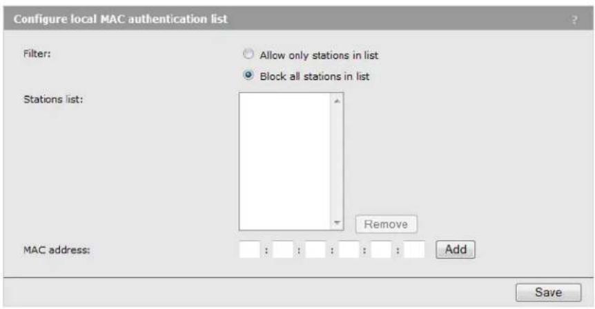
Filter
Select one of the following options:
- Allow only stations in list: Only users whose MAC addresses appear in the MAC address list can connect to the wireless network created by this community.
- Block all stations in list: Users whose MAC address appear in the MAC address list are blocked from accessing the wireless network created by this community.
Stations list
Up to 512 MAC addresses are supported. To remove an address, select it in the list and select Remove.
MAC address
To add a MAC address, specify six pairs of hexadecimal digits separated by colons (for example, 00:00:00:0a:0f:01), and then select Add. The added address appears in the Stations list.
5 Wireless configuration
Wireless coverage
As a starting point for planning your network, you can assume that when operating at high power, the M220 radio provides a wireless networking area (also called a wireless cell) of up to 300 feet (100 meters) in diameter. Before creating a permanent installation, you should always perform a site survey to determine the optimal settings and location for the M220.
The following sections provide information on wireless coverage. A tool that can help simplify planning a secure wireless network is the HP RF Planner (available separately). For more information, see the RF Planner Admin Guide or contact your HP Partner.
Factors limiting wireless coverage
Wireless coverage is affected by the factors discussed in this section.
Interference
Interference is caused by other APs or devices that operate in the same frequency band as the M220 and can substantially affect throughput. Several tools are available to diagnose interference problems as they occur.
- Select Wireless > Rogue AP detection to view detailed information about all wireless APs operating in the immediate area so that you can effectively set the operating frequencies. This feature also makes it easy for you to find rogue APs. See Detecting Rogue APs on page 58.
- Select Status > Wireless to view detailed information about packets sent and received, transmission errors, and other low-level events.
Caution
APs that operate in the 2.4 GHz band may experience interference from devices including 2.4 GHz cordless phones and microwave ovens. A smaller but growing number of devices are potential sources of interference in the 5 GHz band.
Physical characteristics of the location
To maximize coverage of an M220, install it in an open area with as few obstructions as possible. Try to choose a location that is central to the area being served.
Radio waves cannot penetrate metal—they are reflected instead. The M220 can transmit through wood or plaster walls and closed windows (although window glazing or thickness may impair penetration). However, the steel reinforcing found in concrete walls and floors may block transmissions or reduce signal quality by creating reflections. This can make it difficult or impossible for a single M220 to serve users on different floors in a concrete building. Such installations require a separate M220 on each floor.
Configuring overlapping wireless APs
When the radio is operating in the 2.4 GHz band and two or more APs are within transmission range of each other, they may use overlapping channels. This may be under your control (for example, when you use several APs to cover a large location) or out of your control (for example, when your neighbors set up their own wireless networks). In either case, the problems you face are similar.
Note
Overlapping channels do not occur when the radio is operating in the 5 GHz band. All 5 GHz channels are non-overlapping.
Performance degradation and channel separation
When two wireless APs operating on the same frequency overlap, throughput can be reduced in both APs. Reduced throughput occurs because a wireless user that is attempting to transmit data defers (delays) transmission if another station is transmitting. In a network with many users and much traffic, these delayed transmissions can severely affect performance, because wireless users may defer several times before the channel becomes available. If a wireless user is forced to delay transmission too many times, data can be lost.
Delays and lost transmissions can severely reduce throughput on a network. To view this information about your network, select Status > Wireless.
The following example shows two overlapping wireless APs operating on the same frequency. Since the APs are within range of each other, the number of deferred transmissions can be large.

The solution to this problem is to set the two networks to different channels with as great a separation as possible in their operating frequencies. This reduces crosstalk and enables wireless clients connected to each M220 to transmit at the same time.

Selecting channels
For optimal performance when operating in the 2.4 GHz band, select an operating frequency that is different by at least 25 MHz from the frequency used by neighboring APs.
Two channels with the minimum 25 MHz frequency separation always perform worse than two channels that use maximum separation. It is always best to use the greatest separation possible between overlapping networks.
With the proliferation of wireless networks, it is very possible that the areas of coverage of APs outside your control overlap your intended area of coverage. To choose the best operating frequency, select Wireless > Rogue AP detection to generate a list of all APs that operate near you and their operating frequencies.
The number of non-overlapping channels available to you varies by geographical location, which affects how you set up your network when multiple APs are present.
Sample channel selections
For example, when operating in 802.11b mode, the M220 supports the following 14 channels in the 2.4 GHz band:
| Channel Frequency Channel Frequency | |||
| 1 | 2412 | 8 | 2447 |
| 2 | 2417 | 9 | 2452 |
| 3 | 2422 | 10 | 2457 |
| 4 | 2427 | 11 | 2462 |
| 5 | 2432 | 12 | 2467 |
| 6 | 2437 | 13 | 2472 |
| 7 | 2442 | 14 | 2477 |
However, the number of channels available for use in a particular country is determined by regional regulations. The following table shows the number of channels that are available in North America and Europe:
| Region Available channels | |
| North America 1 to 11 | |
| Europe 1 to 13 |
Since the minimum recommended separation between overlapping channels is 25 MHz (in other words, they must be at least five channels apart), the recommended maximum number of overlapping APs you can have in most regions is three. The following table gives examples relevant to North America and Europe for channels in the 2.4 GHz band:
| North America Europe | |
| AP 1 on channel 1AP 2 on channel 6AP 3 on channel 11 | AP 1 on channel 1AP 2 on channel 7AP 3 on channel 13 |
In North America, you can reduce transmission delays by using different operating frequencies, as shown in the following figure:

Alternatively, you can stagger APs to reduce overlap and increase channel separation, as shown in the following figure:

This strategy can be expanded to cover an even larger area using three channels, as shown in the following figure:

802.11n best practices
This section provides recommendations on how to best use 802.11n wireless technology, especially when legacy (a/b/g) clients must also be supported.
Supporting legacy wireless clients
The 802.11n standard is very similar to the 802.11g standard, in that both provide mechanisms to support older wireless standards. In the case of 802.11g, protection mechanisms were created to allow 802.11b and 802.11g wireless devices to co-exist on the same frequencies despite using different signal modulation schemes. Since older 802.11b-only clients cannot detect the newer 802.11g modulation scheme, 802.11g clients must “protect” their transmissions by first sending a signal that alerts 802.11b clients to not attempt to transmit for a specified period of time.
If protection is not used, 802.11b clients may transmit while an 802.11g frame is already being sent. This leads to a collision and both devices need to re-transmit. If there are enough devices in the network, the collision rate will grow exponentially and prevent any useful throughput from the wireless network.
802.11n clients face the same problem as described for 802.11g clients. Legacy a/b/g clients cannot detect the High Throughput (HT) rates that 802.11n uses. To avoid causing excessive collisions, 802.11n clients must use the same protection mechanisms when a legacy client is present. Even the most efficient protection mechanism (CTS-to-self) causes a substantial decline in throughput. Performance can decline by as much as 50 percent. The 802.11n clients can achieve maximum data rates only when the legacy clients are not present.
Compatibility modes
See Basic settings on page 53 for a list of supported modes.
Modes that support multiple 802.11 standards are referred to as compatibility modes. IEEE 802.11b/g/n is the default mode.
For compatibility modes that support 802.11n clients, the M220 advertises protection in its beacon frames when legacy clients are associated or operating on the same channel. This alerts the associated 802.11n clients to use protection when transmitting. The M220 also uses protection when necessary while sending HT data.
Compatibility modes should be used when legacy clients are present in the network. HP recommends IEEE 802.11a/n or IEEE 802.11 b/g/n as the typical operating mode. Both modes allow for all wireless clients to connect and they use protection to avoid causing interference.
IEEE 802.11n (5 GHz) and IEEE 802.11n (2.4 GHz)
HP refers to these two modes as Pure-n. When the M220 radio is in either of these modes, it will not allow non-802.11n clients to associate. Legacy clients can see the M220, and may attempt to associate, but they will be rejected. The M220 makes this determination based on information on supported capabilities that the client presents during its association request. If the client does not indicate support for 802.11n capabilities, it is not allowed to associate.
In these modes, the M220 will not use protection when sending HT frames to associated clients. If legacy APs or clients are using the same channel, this may lead to collisions. In the 5 GHz band, this will probably not be a common problem since the band is not heavily used. In the 2.4 GHz band, however, this mode may cause serious performance deterioration for everyone on the channel (both the 802.11b/g and 802.11n clients).
The M220 will still signal associated clients to use protection when they send data. The M220 does this via a field in the beacons that it sends. So clients sending data to the M220 will use protection, but data sent from the M220 will not be protected.
Some people may refer to this mode as Greenfield, which is not correct. Greenfield is an 802.11n-specific preamble. The M220 does not support this preamble and therefore does not support Greenfield mode.
The Pure-n modes can be used when there is no legacy wireless traffic present in or around the premises on the channels that will be used. All client devices must support 802.11n.
Channel width
When operating in an 802.11n mode, the M220 enables you to use the standard channel width of 20 MHz or a double width of 40 MHz. A width of 40 MHz is achieved by using two adjacent channels to send data simultaneously. The advantage of using a 40 MHz wide channel is that the available bandwidth is doubled, leading to much higher throughput for clients operating in that mode. A disadvantage is that fewer channels are available for use by all clients.
When the channel width is set to 20 MHz, channel usage is the same as in legacy mode.
When Auto (20/40) is selected, the M220 radio uses a 40 MHz channel width. However, both 20 and 40 MHz clients can associate. The channel selected on the Modify radio settings page is the primary channel and the secondary (or extension) channel is located adjacent to it. The secondary channel is either above or below depending on which channel was selected as the primary. In 5 GHz IEEE 802.11n mode, the channels are paired: for example, channels 36
and 40 are always used together, 44 and 48 are always used together, etc.
Note
If the Country setting identifies a regulatory domain that does not support the 40 MHz channel bandwidth, this setting will not apply.
Radio configuration
To define configuration settings for the M220 radio, select Wireless > Radio. The Modify radio settings page displays.

This page enables you to configure the country in which the M220 will operate, basic radio settings such as the radio mode and channel, and advanced radio features.
Country
The country of operation, also known as the regulatory domain, determines the availability of certain wireless settings on the M220.
Once the country has been set, the M220 automatically limits the available wireless channels and channel width, and adjusts the radio power level in accordance with the regulations of the selected country.
Caution
Incorrectly selecting the country may result in illegal operation and may cause harmful interference to other systems. Please ensure that the M220 is operating in accordance with channel, power, indoor/outdoor restrictions, and license requirements for the intended country. If you fail to heed this caution, you may be held liable for violating the local regulatory compliance.
Basic settings
Radio
The wireless radio is enabled by default. If you disable the radio, no wireless clients can connect.
Mode
Select the mode that best supports the wireless clients at your location.
Supported wireless modes are determined by the regulatory domain (country). Available options may include one or more of the following:
- IEEE 802.11a: Up to 54 Mbps for 802.11a in the 5 GHz frequency band.
- IEEE 802.11b/g: (Compatibility mode.) Up to 11 Mbps for 802.11b and 54 Mbps for 802.11g in the 2.4 GHz frequency band. Use this setting only when support for 802.11b is necessary and support for 802.11n is not desired.
- IEEE 802.11a/n: (Compatibility mode.) Up to 54 Mbps for 802.11a and 300 Mbps for 802.11n in the 5 GHz frequency band.
- IEEE 802.11 b/g/n: (Compatibility mode.) Up to 300 Mbps for 802.11n, 54 Mbps for 802.11g, and 11 Mbps for 802.11b in the 2.4 GHz frequency band. Use this setting when support for 802.11b and 802.11n is necessary.
- IEEE 802.11n (5 GHz): (Pure 802.11n) Up to 300 Mbps in the 802.11n 5 GHz frequency band.
- IEEE 802.11n (2.4 GHz): (Pure 802.11n) Up to 300 Mbps in the 802.11n 2.4 GHz frequency band.
Note
In 802.11n (2.4 GHz) and 802.11n (5 GHz) modes, the M220 does not permit non-802.11n clients to associate. Also in this mode, the M220 does not use protection mechanisms (RTS/CTS or CTS-to-self) to enable legacy APs to operate on the same frequency. This can potentially cause problems with legacy (802.11a/b/g) APs operating on the same channel, but provides the best throughput for the M220 and its 802.11n clients.
In 802.11 a/n, and 802.11 b/g/n modes, the M220 permits both 802.11n and legacy clients (802.11a/b/g) to associate. The M220 uses protection mechanisms (RTS/CTS or CTS-to-self) when sending 802.11n data to prevent disruption to legacy (802.11a/b/g) clients associated on the same channel. For more information, refer to 802.11n best practices on page 50.
Channel
Select the channel for wireless services. The range of available channels is determined by the mode of the radio interface and the country code setting.
• Automatic channel selection
If you select Auto for the channel setting, the AP randomly selects a channel from the list of valid channels for the country and radio mode.
The channel defines the portion of the radio spectrum the radio uses for transmitting and receiving. Each mode offers a number of channels, depending on how the spectrum is licensed by national and transnational authorities such as the Federal Communications Commission (FCC) or the International Telecommunication Union (ITU-R).
• Manual channel selection
If setting the channel manually, for optimal performance when operating in 2.4 GHz modes, select a channel that is different by at least five channel numbers (25 MHz) from the channels used on wireless APs that have overlapping coverage areas. For example, if another AP is operating on channel 1, set the M220 to channel 6 or higher. Select Wireless > Rogue AP detection to view a list of APs currently operating in your area.
When operating in 802.11a or 5 GHz 802.11n modes, all channels are non-overlapping, so you can configure APs to operate on adjacent channels.
Note
Channel selection for APs in a cluster: When automatic channel assignment is enabled on the Cluster > Channel planning page, the channel policy for the radio is automatically set to static mode, and the Auto option is not available for the Channel setting. This configuration allows the automatic channel feature to set the channels for the radios in the cluster.
Channel bandwidth
(Only applicable when Wireless mode includes some type of 802.11n support.)
Select the Channel width that will be used for 802.11n users.
• 20 MHz: Sets channel width to 20 MHz.
- Auto 20/40 MHz: Under most conditions, this can double throughput by bonding adjacent channels to form a 40 MHz channel. This option reduces the number of unoccupied channels available to neighboring APs.
Note
Although some 802.11n clients only support 20 MHz channels, they can still associate with a M220 configured for Auto 20/40 MHz.
Primary channel (802.11n modes only)
This setting can be changed only when the channel bandwidth is set to 40 MHz. A 40-MHz channel can be considered to consist of two 20-MHz channels that are contiguous in the frequency domain. These two 20-MHz channels are often referred to as the Primary and Secondary channels. The Primary channel is used for 802.11n clients that support only a 20 MHz channel bandwidth and for legacy clients.
Select one of the following options:
• Upper: The Primary Channel is the upper 20-MHz channel in the 40-MHz band. • Lower: The Primary Channel is the lower 20-MHz channel in the 40-MHz band.
Current channel
This field displays the currently assigned channel.
Station isolation
When enabled, the M220 prevents communication between wireless clients associated with the same wireless community. Clients can still communicate with the wired network, across a WDS link, and with other wireless clients associated with a different wireless community. This selection is applied to all wireless communities on the AP.
Advanced radio settings
When you select the + next to Advanced radio settings, the following settings display:
Multidomain regulatory mode
This mode causes the AP to broadcast, as a part of its beacons and probe responses, the country in which it is configured for operation. This allows wireless clients to operate in any country without reconfiguration.
Disabling this feature prevents the country code setting from being broadcast in the beacons. However, this applies only to radios configured to operate in the 802.11g band (2.4 GHz). For radios operating in the 802.11a band (5 GHz), the AP software configures support for the IEEE standard 802.11h. When 802.11h is supported, the country code information is broadcast in the beacons.
Short guard interval supported
This setting is available only if the selected radio mode includes 802.11n.
The guard interval is the dead time, in nanoseconds, between symbols (or characters) transmitted by the AP. The guard interval helps distinguish where one symbol transmission stops and another starts, thereby reducing inter-symbol interference (ISI). The 802.11n mode allows for a reduction in this guard interval from the 802.11a and 802.11g definition of 800 nanoseconds to 400 nanoseconds. Enabling the short guard interval (SGI) is recommended, as it can yield a 10% improvement in data throughput.
Note
If SGI is enabled on the M220 but a wireless client does not support SGI, the client will be able to communicate with M220 at a data rate that is about 10% slower than SGI-enabled clients.
Select one of the following options:
- Yes (default): AP transmits data using a 400 ns guard interval when communicating with clients that also support the short guard interval. • No: The AP transmits data using an 800 ns guard interval.
STBC mode
This setting is available only if the selected radio mode includes 802.11n.
Space Time Block Coding (STBC) is an 802.11n technique that improves the reliability of data transmissions. The data stream is transmitted on multiple antennas so the receiving system has a better chance of detecting at least one of the data streams. Enabling STBC results in a lower but more stable throughput.
Select one of the following options:
- On: AP transmits the same data stream on multiple antennas at the same time.
- Off: The AP does not transmit the same data on multiple antennas.
Protection
The protection feature provides rules to guarantee that 802.11n and 802.11g transmissions do not cause interference with legacy stations or applications. By default, these protection mechanisms are enabled (Auto). With protection enabled, protection mechanisms will be invoked if legacy devices are within range of the AP.
You can disable these protection mechanisms (Off). When protection is off, however, legacy clients or APs within range can be affected by 802.11n transmissions. Protection is also available when the mode is 802.11b/g. When protection is enabled in this mode, it protects 802.11b clients and APs from 802.11g transmissions.
Note
This setting does not affect the ability of the client to associate with the AP.
Beacon interval
Beacon frames are transmitted by an AP at regular intervals to announce the existence of the wireless network. The default behavior is to send a beacon frame once every 100 milliseconds (10 per second).
Enter a value from 20 to 2000 milliseconds.
DTIM period
Specify a DTIM period from 1 to 255 beacons.
The Delivery Traffic Information Map (DTIM) message is an element included in some beacon frames. It indicates which wireless clients, currently sleeping in low-power mode, have data buffered on the AP awaiting pickup.
The DTIM period you specify indicates how often the clients served by this AP should check for buffered data still on the AP awaiting pickup.
The measurement is in beacons. For example, if you set this field to 1, clients will check for buffered data on the AP at every beacon. If you set this field to 10, clients will check on every 10th beacon.
Fragmentation threshold
Specify a number from 256 to 2,346 to set the frame size threshold in bytes.
The fragmentation threshold is a way of limiting the size of frames transmitted over the network. If a frame exceeds the fragmentation threshold you set, the fragmentation function is activated and the frame is sent as multiple 802.11 frames.
If the frame being transmitted is equal to or less than the threshold, fragmentation is not used.
Setting the threshold to the largest value (2,346 bytes) effectively disables fragmentation.
Fragmentation involves more overhead because it requires the extra work of dividing up and reassembling frames and it increases message traffic on the network. However, fragmentation can help improve network performance and reliability if properly configured.
Sending smaller frames (by using lower fragmentation threshold) might help with some interference problems; for example, with microwave ovens.
By default, fragmentation is off. HP recommends not using fragmentation unless you suspect radio interference. The additional headers applied to each fragment increase the overhead on the network and can greatly reduce throughput.
RTS threshold
Specify a Request to Send (RTS) threshold value from 0 to 2347.
The RTS threshold indicates the number of octets in an MPDU below which an RTS/CTS handshake is not performed.
Changing the RTS threshold can help control traffic flow through the AP, especially one with many clients. If you specify a low threshold value, RTS packets will be sent more frequently. This will consume more bandwidth and reduce packet throughput on the AP. On the other hand, sending more RTS packets can help the network recover from interference or collisions that might occur on a busy network or on a network experiencing electromagnetic interference.
Transmit power
Enter a percentage value for the transmit power level for this AP.
The default value, which is 100%, can be more cost-efficient than a lower percentage, since it gives the AP a maximum broadcast range and reduces the number of APs needed to cover an area.
To increase the capacity of the network, place APs closer together and reduce the value of the transmit power. This helps reduce overlap and interference among APs. A lower transmit power setting can also keep your network more secure because weaker wireless signals are less likely to propagate outside of the physical location of your network.
Fixed multicast rate
This value sets a fixed transmission rate in Mbps for broadcast and multicast packets. This setting can be useful in an environment where wireless multicast video streaming occurs, provided the wireless clients are capable of handling the configured rate.
Note
There is no prioritization or quality of service handling for multicast traffic because the M220 AP supports only one multicast queue.
Select Auto to have the M220 choose the best rate automatically. The range of valid values is determined by the configured radio mode. The default value is Auto.
Bcast/Mcast rate limiting
Enabling multicast and broadcast rate limiting can improve overall network performance by limiting the number of packets transmitted across the network. Note, however, that the performance of client applications that rely on multicast or broadcast traffic may be affected.
The rate limit applies only to traffic flowing in the downstream direction, from the AP to wireless clients.
By default, this option is disabled. When you enable it, the following fields are editable:
Rate limit
Enter the rate limit you want to set for multicast and broadcast traffic. The limit should be greater than 1 but less than 50 packets per second. Any traffic that falls below this rate limit will always conform and be transmitted to the appropriate destination.
The default and maximum rate limit setting is 50 packets per second.
Rate limit burst
The rate limit burst sets a threshold rate for traffic bursts, above which all traffic is considered to exceed the rate limit. This burst limit allows intermittent bursts of traffic that are above the set Rate limit, but below the Rate limit burst.
The default and maximum rate limit burst setting is 75 packets per second.
Detecting Rogue APs
You can use the Rogue AP detection feature to scan for other APs operating nearby. Initially, new APs on the network are identified as rogue APs. If you are aware of an AP detected as a rogue AP, and know that its existence on your network is legitimate, you can identify it as a known AP so that it will not continue to be detected as a rogue AP. This is useful for monitoring the installation of wireless APs in your company's work areas to ensure that new APs (which could be a security risk if improperly configured) are not deployed without your knowledge.
This feature can also be used to determine the operating frequencies and signal strengths of nearby APs for site planning purposes.
Enabling scanning
Scanning for rogue APs is enabled by default. To disable it, select Wireless > Rogue AP detection, select Disabled next to AP detection, and then select Save.

When enabled, the AP initiates a scan on a single channel. Every 60 seconds, the AP scans the next sequential channel. The scan duration is 10 ms per channel.
Note
- Scanning is temporarily disabled when a trace is active (see the Tools > Network trace page).
- Although the impact of scanning on AP performance is expected to be minimal, to obtain the best possible wireless performance (as needed for voice applications, for example), disable scanning.
Detected and Known AP lists
When the M220 discovers an AP during a scan, it compares the MAC address of the AP against the Known AP list (a list that you create or import using the capabilities on this page). If the scanned AP does not appear in the list of known APs, it is displayed in the Detected rogue AP list.
| Detected rogue AP list | |||||||||||
| Action | MAC | Beacon int. | Type | SSID | Privacy | WPA | Band | Channel | Rate | Signal | Beacons |
| Grant | 00:53:43:4f:54:54 | 100 | AP | JPW_551 | On | On | 2.4 | 1 | 1 | 2 | |
| Grant | 5c:d9:98:2f:3f:10 | 100 | AP | A-TEST-2G | On | On | 2.4 | 3 | 1 | 790 | |
| Grant | 00:21:29:00:0d:20 | 100 | AP | MJFLSrlv0 | Off | Off | 2.4 | 6 | 1 | 2421 | |
| Grant | 00:53:43:1a:22:0f | 100 | AP | ap1 r1 bgn vap15 | On | On | 2.4 | 6 | 1 | 157 | |
| Grant | 00:10:18:92:fd:70 | 100 | AP | HP | Off | Off | 2.4 | 6 | 1 | 922 | |
| Grant | 00:53:43:1a:22:00 | 100 | AP | ap1 r1 bgn vap0 wpsPsk | On | On | 2.4 | 6 | 1 | 29 | |
| Grant | 00:53:43:1a:22:02 | 100 | AP | ap1 r1 bgn vap2 | On | On | 2.4 | 6 | 1 | 4 | |
| Grant | 00:53:43:1a:22:01 | 100 | AP | ap1 r1 bgn vap1 | On | On | 2.4 | 6 | 1 | 17 | |
| Grant | 00:11:21:61:6e:30 | 100 | AP (Non Broadcasting) | On | On | 2.4 | 10 | 1 | 6213 | ||
| Grant | 00:90:4c:01:66:43 | 100 | AP Virtual Access Point 3 Off | ||||||||
The following information displays for each detected rogue AP:
| Field Description | |
| MAC | The MAC address of the neighboring AP detected during a scan. |
| Beacon Int. | The Beacon interval being used by this AP. Beacon frames are transmitted by an AP at regular intervals to announce the existence of the wireless network. The default behavior is to send a beacon frame once every 100 milliseconds (10 per second). |
| Type The type of | device:AP indicates the neighboring device is an AP that supports the IEEE 802.11 Wireless Networking Framework in Infrastructure mode.Ad hoc indicates a neighboring wireless client device running in Ad hoc mode. Devices set to Ad hoc mode communicate with each other directly, without the use of a traditional AP. Ad hoc mode is an IEEE 802.11 Wireless Networking Framework also referred to as peer-to-peer mode or an Independent Basic Service Set (IBSS). |
| SSID | The Service Set Identifier (SSID) for the AP.The SSID uniquely identifies a wireless LAN and is also referred to as the Network Name. It can be up to 32 alphanumeric characters. |
| Field | Description |
| Privacy Whether | there is any security on the neighboring device.Offindicates that the Security mode on the neighboring device is set to None (no security).Onindicates that the neighboring device has some security in place. |
| WPA Whether | WPA security is on or off for this AP. |
| Band The 802.1 | 1 band used on this AP, as follows:2.4indicates 802.11b, 802.11g, or 802.11n mode (or a combination of the modes).5indicates 802.11a or 802.11n mode (or both modes). |
| Channel | The channel on which the AP is currently broadcasting.The channel defines the portion of the radio spectrum that the radio uses for transmitting and receiving.The channel is set in the Radio settings. (See “Radio configuration” on page 52.) |
| Rate The rate (in | megabits per second) at which this AP is currently transmitting. |
| Signal | The detected strength of the radio signal from this AP. If you hover the mouse pointer over the bars, a number appears and shows the strength in decibels (dB). |
| Beacons The total | number of beacons received from this AP since it was first discovered. |
For any AP that is known to you, you can select Grant to move the AP to the Known AP list.
| Known AP list | ||||||
| Action | MAC | Type | SSID | Privacy | Band | Channel |
| Delete | 00:53:43:1a:22:01 | AP | ap1 r1 bgn vap1 | On | 2.4 | 6 |
| Delete | 00:21:29:00:0d:20 | AP | MJFLSr1v0 | Off | 2.4 | 6 |
| Delete | 00:53:43:1a:22:0f | AP | ap1 r1 bgn vap15 | On | 2.4 | 6 |
You can select Delete to remove an AP from the Known AP list.
Note
The Detected rogue AP list and Known AP list provide information only. The M220 does not have control over the APs on these lists and cannot apply any security policies to them.
Working with saved AP lists
You can save the Known AP list and import a saved list to the M220. A saved list can show APs that you previously identified as known APs but that may not be showing in the current Detected rogue AP list (because they are not currently operational, for example).
To create a list, under Save AP list, select Save and then save the file to your PC or network.
Save AP list
Save the known AP list to a file.
Save
By default, the filename is Rogue2.cfg. You can use a text editor or web browser to open the file and view its contents.
In the Import AP list section, you can import a list that was previously saved from this AP or from another M220.
Import AP list
Replace or merge to known AP list:
Filename:

Replace
Merge
Browse_
Import
Select one of the following options:
- Replace: The imported list will replace the Known APs list.
- Merge: APs from the imported list are added to the existing Known APs list.
Browse to select the file to import, and select Import. The new list displays in the Known AP list.
Viewing wireless information
The M220 provides several pages where you can view information related to wireless operation.
Viewing all connected wireless clients
Select Wireless > Client connections.
The following information is displayed for each client currently connected to the M220:
| Field Description | |
| Network The wireless com | munity the client is associated with. For example, an entry of wlan0vap2 means the client is associated with wireless community 2. |
| Station The MAC address of | the associated wireless client. |
| Status (Auth and Assoc) | The underlying IEEE 802.11 authentication and association status, which is present no matter which type of security the client uses to connect to the AP. This status does not show IEEE 802.1X authentication or association status.Keep the following points in mind with regard to this field:If the Security method is None or Static WEP, the authentication and association status of clients showing on the Client associations page will be in line with what is expected; that is, if a client shows as authenticated to the AP, it will be able to transmit and receive data. (This is because Static WEP uses only IEEE 802.11 authentication.)If the Security method is IEEE 802.1X, WPA Personal, or WPA Enterprise, it is possible for a client to show on this tab as authenticated (via the IEEE 802.11 security) but actually not be authenticated to the AP via the second layer of security. |
| From station The number of packets and bytes received from the wireless client and the number of packets and bytes that were dropped after being received. | |
| To station The number of packets and bytes transmitted from the AP to the wireless client and the number of packets and bytes that were dropped upon transmission. | |
Viewing wireless statistics for the radio
Select Status > Wireless to display the Wireless status page.
| Wireless status | |
| WLAN packets received | 0 |
| WLAN bytes received | 0 |
| WLAN packets transmitted | 697 |
| WLAN bytes transmitted | 101750 |
| WLAN packets receive dropped | 0 |
| WLAN bytes receive dropped | 0 |
| WLAN packets transmit dropped | 0 |
| WLAN bytes transmit dropped | 0 |
| Fragments received | 0 |
| Fragments transmitted | 0 |
| Multicast frames received | 0 |
| Multicast frames transmitted | 697 |
| Duplicate frame count | 0 |
| Failed transmit count | 0 |
| Transmit retry count | 0 |
| Multiple retry count | 0 |
| RTS success count | 0 |
| RTS failure count | 0 |
| ACK failure count | 0 |
| FCS error count | 50416 |
| Transmitted frame count | 697 |
| WEP undecryptable count | 0 |
This page displays the following information:
| Field Description | |
| WLAN packets received | Total packets received by the AP. |
| WLAN bytes received Total bytes received by the AP. | |
| WLAN packets transmitted | Total packets transmitted by the AP. |
| WLAN bytes transmitted | Total bytes transmitted by the AP. |
| WLAN packets receive dropped | Number of packets received by the AP that were dropped. |
| WLAN bytes receive dropped | Number of bytes received by the AP that were dropped. |
| WLAN packets transmit dropped | Number of packets transmitted by the AP that were dropped. |
| WLAN bytes transmit dropped | Number of bytes transmitted by the AP that were dropped. |
| Fragments received Count of successfully received MPDU frames of type data or management. | |
| Fragments transmitted | Number of transmitted MPDU with an individual address or an MPDU with a multicast address of type data or management. |
| Multicast frames received | Count of MSDU frames received with the multicast bit set in the destination MAC address. |
| Multicast frames transmitted | Count of successfully transmitted MSDU frames where the multicast bit is set in the destination MAC address. |
| Duplicate frame count | Number of times a frame is received and the Sequence Control field indicates it is a duplicate. |
| Failed transmit count | Number of times an MSDU is not transmitted successfully due to transmit attempts exceeding either the short retry limit or the long retry limit. |
| Transmit retry count | Number of times an MSDU is successfully transmitted after one or more retries. |
| Multiple retry count | Number of times an MSDU is successfully transmitted after more than one retry. |
| RTS success count | of CTS frames received in response to an RTS frame. |
| RTS failure count | of CTS frames not received in response to an RTS frame. |
| ACK failure count | of ACK frames not received when expected. |
| FCS error count | FCS errors detected in a received MPDU frame. |
| Transmitted frame count | Count of each successfully transmitted MSDU. |
| WEP undecryptable count | Count of encrypted frames received and the key configuration of the transmitter indicates that the frame should not have been encrypted or that frame was discarded due to the receiving station not implementing the privacy option. |
6 Creating WDS links
Key concepts
The Wireless Distribution System (WDS) feature enables you to create point-to-point wireless links between one or more M220s. These links create a wireless bridge that interconnects the networks connected to the Ethernet port on each M220. For example, in the following figure, M220 #2 and M220 #3 use the WDS to create a wireless link between the main office network and a small network in a warehouse:
![graph TD A["File server DHCP server"] --> B["M220 #2"] C["Employee computers"] --> B B --> D["WDS Wireless link"] D --> E["M220 #3"] E --> F["Wireless community"] E --> G["Computer 1"] E --> H["Computer 2"] E --> I["Computer 3"] J["Wireless community"] --> K["M220 #1"] K --> L["Computer 1"] K --> M[…](/content/2026/06/1344351/images/0ecbb1b2dfcfa54eb1164bb03f420a6dc15fea6c4bda6e1450e0d8594adb473d.jpg)
WDS links provide an effective solution for extending network coverage in situations where it is impractical or expensive to run cabling. Each M220 can create up to four WDS links.
Note
A network that includes WDS links should be distinguished from a group of clustered APs. WDS enables wirelessly extending the network, whereas clustering is used to simplify AP administration and optimize bandwidth use. See Clustering multiple M220s on page 79 for more information.
Simultaneous AP and WDS support
The M220 simultaneously supports wireless communities and one or more WDS links. Although this offers flexibility, note that the total available bandwidth on the radio is shared between all WDS links and wireless users. This can result in reduced throughput if high volumes of traffic are being sent by both wireless users and the WDS links.
Using the 5 GHz band for WDS links
When the M220 uses WDS only to extend the network by providing a dedicated link to another M220 (that is, it does not simultaneously act as an AP for wireless clients), it is recommended that, whenever possible, the WDS links use 802.11n or 802.11a in the 5 GHz band. This optimizes throughput and reduces the potential for interference, as follows:
- Most Wi-Fi clients support 802.11b or b/g; therefore, most APs are set to operate in the 2.4 GHz band. This frees the 5 GHz band for other applications such as WDS.
- 802.11a and 802.11n channels in the 5 GHz band are non-overlapping. • Assuming an optimal implementation, 802.11a supports up to 54 Mbps and 802.11n supports up to 300 Mbps, providing a fat pipe for traffic exchange.
Configuration considerations
The following guidelines apply when you create a WDS link between two or more M220s:
- The 5 GHz band has a shorter reach when compared to the 2.4 GHz band. This could be a factor depending on the distance your WDS link span.
- All radios must be set to the same operating frequency and channel. This means that on the Wireless > Radio page under Channel, you cannot select Auto.
- The Ethernet ports for all M220s must be connected to the same subnet, and each M220 must have a unique IP address.
- If WPA (PSK) security is enabled, the same link name and key must be defined on all M220s that are linked by the WDS connection.
- IEEE 802.11n uses frame aggregation, whereby multiple frames are combined into one to reduce overhead and increase throughput. WEP-encrypted frames are not aggregated, however, so enabling WEP security over WDS will result in reduced throughput.
- Although the M220 can support up to four WDS links, only one wireless link can be defined between any two M220s.
WDS configuration
To view or add a WDS link, select Wireless > WDS.

General
Local address
Shows the MAC address of the wireless port on the M220. This address needs to be entered on the M220 to which this link will connect.
Spanning tree mode
The Spanning-Tree Protocol (STP) can be enabled to prevent undesirable loops from occurring in the network that may result in decreased throughput. Enabling spanning tree is recommended.
WDS link 1/2/3/4
You can link the M220 with up to four other M220 devices. Specify the following settings for each WDS interface:
Remote address
Specify the MAC address of the wireless port on the remote M220 to which this link will connect. Or, click the left arrow next to the text box to select from a list of MAC addresses detected during an AP scan. The MAC address must be in the following format: six pairs of hexadecimal numbers, (including numbers 0 to 9 and letters a to f or A to F), with each pair separated by a colon. For example: 00:03:52:0a:0f:01.
Encryption
Select how traffic exchanged between the two M220s will be encrypted.
The options are as follows:
- None: Data is transmitted unencrypted between M220 devices.
- WEP: Note that IEEE802.11n uses frame aggregation, whereby multiple frames are combined into one to reduce overhead and increase throughput. WEP-encrypted frames are not aggregated, however, so enabling WEP security over WDS will result in reduced throughput.
To enable WEP, configure the following settings:
• Key length: Select 64 bits or 128 bits. • Key type: Select ASCII or Hex. - WEP key: If you selected ASCII, enter any combination of 0 to 9, a to z, and A to Z, and special characters such as @ and #. If you selected Hex, enter hexadecimal digits (any combination of 0 to 9 and a to f or A to F). These are the RC4 encryption keys shared with the stations using the AP. - Confirm key: Re-enter the key.
• WPA (PSK): Configure the following settings:
- Link name: Enter a name for the new WDS link you have created. It is important that the same link name is entered at the other end of the WDS link. If this name is not the same for both APs on the WDS link, they will not be able to communicate and exchange data.
The name can be any alphanumeric combination.
- Key: Enter a unique shared key for the WDS link. This unique shared key must also be entered for the AP at the other end of the WDS link. If this key is not the same for both APs, they will not be able to communicate and exchange data.
The WPA-PSK key uses AES encryption. It can be from 8 to 63 characters. Acceptable characters include upper and lower case alphabetic letters, the numeric digits, and special symbols such as @ and #. The key cannot begin with or end with spaces and cannot contain only spaces.
- Confirm key: Re-enter the key.
Sample WDS deployment
This example shows you how to create a wireless link between two physically separate network segments.
![graph LR A["DHCP server"] -->|5.1| B["M220 #1"] C["Computer"] -->|5.15| B D["Computer"] -->|5.165.2| B B -->|192.168.5.10| E["WDS Wireless link"] E -->|192.168.5.20| F["M220 #2"] F -->|WDS Wireless link| E G["Computer"] --> H["Computer"] I["Computer"] --> J["Computer"]](/content/2026/06/1344351/images/3f9e63d9ef283b610713e395be297c8d1c5e8bbeecd0c804580926298abb4160.jpg)
This example assumes that both M220s have their IP addresses set and are connected to their respective networks as shown in the diagram.
A. Obtain the MAC address of M220 #2
- Click the left arrow next the Remote address text box and select the MAC address of the remote M220. Or, if you cannot identify it in the list, connect to the management tool on M220 #2, open the home page, and write down its MAC address.
B. Set up the WDS link on M220 #1
- Open the management tool on M220 #1.
- Select Wireless > Radio to display the Modify radio settings page.
- In the Basic settings area, configure the following:
- Set Mode to 5 GHz IEEE 802.11n.
- Set Channel to 36.
- Select Save.

- Select Wireless > WDS.
- Under WDS link 1, configure the following settings:
- If not already selected, set Remote address to the MAC address of M220 #2.
- Set Encryption to WPA (PSK).
- Set the Link name to M220_WDS1.
- Set Key to a39xm210.
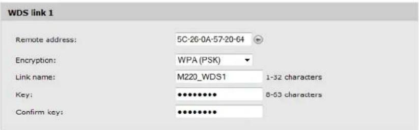
- Select Save.
C. Setup the WDS link on M220 #2
Configuration settings on M220 #2 are similar to those defined on M220 #1.
- Open the management tool on M220 #2.
- Select Wireless > Radio.
- In the Basic settings area, configure the following:
- Set Mode to 5 GHz IEEE 802.11n.
- Set Channel to 36.
- Select Save.
- Select Wireless > WDS.
- Under WDS Link 1, configure the following settings:
- Set Remote address to the MAC address of M220 #2.
- Set Encryption to WPA (PSK).
- Set Link name to the same value you entered for the first M220 (M220_WDS1).
- Set Key to a39xm210.
- Select Save.
D. Test the link and make performance adjustments
The WDS link should now be active.
- Select Tools > Ping on M220 #1 and ping the address of M220 #2 (192.168.5.20). If the ping succeeds, it means that the WDS link is working.
- To view the operational status and traffic statistics for the WDS interface on either M220, select Status > Ports.
7 Configuring Ethernet, IP, and VLAN settings
Ethernet configuration
The M220 connects wireless clients to a wired network through its Ethernet port. You can configure the IP settings for this interface and the VLAN membership required for management access to the M220.
To configure the Ethernet port settings, select Network > IP.
Ethernet configuration
MAC address:
Management VLAN ID:
Untagged VLAN:
Untagged VLAN ID:
00:90:4C:08:02:00
1 (1-4094)
Enabled Disabled
1 (1-4094)
The Ethernet configuration area shows the MAC address assigned to the M220 Ethernet port and to the default wireless community (wlan0). The MAC address is also printed on the AP.
This page enables configuring the following settings:
Management VLAN ID
The management VLAN is VLAN 1 by default. If you already have a management VLAN configured on your network with a different VLAN ID, you must change the VLAN ID of the management VLAN on the M220 accordingly. The VLAN ID can be any value from 1 to 4094. Any management traffic received on a different VLAN is ignored.
Untagged VLAN
Untagged VLAN ID
All traffic from wireless clients to the AP is associated with a VLAN ID. The VLAN ID may be assigned by a RADIUS server or determined by the client's association with a wireless community. Traffic between the wired network and the AP, however, might not be associated with a VLAN (that is, the traffic is untagged). These settings determine how the AP forwards untagged traffic to the wireless network.
If the Untagged VLAN option is enabled and an Untagged VLAN ID is specified:
- When the M220 receives traffic from a wireless client and that traffic has a VLAN ID that matches the Untagged VLAN ID, it forwards the traffic to the wired network with no VLAN tag.
- If the VLAN ID does not match the Untagged VLAN ID, the M220 forwards the traffic to the wired network with the VLAN ID from the wireless client.
If the Untagged VLAN option is disabled, all traffic that the M220 receives from a wireless client is forwarded to the wired network with the same VLAN tag it used on the wireless network.
The M220 does not add VLAN tags when forwarding traffic to wireless clients, regardless of whether the traffic was tagged or untagged on the wired network.
By default, this option is enabled and the untagged VLAN ID is 1.
Note
If VLANs are not used on your network, these settings have no effect on the forwarding of traffic.
IPv4 configuration
Use this area to configure the M220 to be assigned an IPv4 address from a DHCP server on your network, or to statically configure an IPv4 address.
Automatically assigning an IP address (default method)
By default, Connection type is set to DHCP and the M220 operates as a DHCP client. This means that if the network has a DHCP server, the M220 will automatically receive a new IP address in place of its default IP address (192.168.1.1) upon connecting to the network.
The DHCP server will assign an address from its pool of available addresses. You can find the IP address of the M220 by looking for its Ethernet base MAC address in the DHCP server log. The Ethernet MAC address is printed on the M220 label identified as Ethernet Base MAC, or listed on the management tool IP page as MAC address.
To have the DHCP server assign a specific IP address to the M220, you need to preconfigure the DHCP server to associate the IP address you want to use with the MAC address of the Ethernet port on the M220.
Static IP configuration
You can manually assign an IP address to the Ethernet port. This requires that you also define the address of the default gateway and DNS server that are in use on your network.
To configure a static IP address, select Network > IP and configure the following fields:
IPv4 configuration
Connection type:
Static IP address:
Subnet mask:
Default gateway:
DNS nameservers:
Static IP ▼
192 . 168 . 1 . 1
255 . 255 . 255 . 0
0.0.0.0
Dynamic Manual
Connection type
Select Static IP from the list to manually configure an IPv4 Ethernet address.
IP address
Set an address that is on the same subnet as the network to which the M220 will connect once installed. Respect any DHCP server-mandated static address ranges.
Subnet mask
Specify the mask for the IP address.
Default gateway
Set the IP address of the gateway on the network.
DNS nameservers:
Select Dynamic to have the DNS nameservers assigned through DHCP, or select Manual to configure up to two static DNS nameserver addresses.
IPv6 configuration
If the attached network uses the IPv6 protocol, you can enable IPv6 support on the M220. IPv6 functionality is enabled by default.
To configure IPv6 functionality, select Network > IP and configure the following fields:
IPv6 configuration
IPv6:
Static IPv6 address:
Static IPv6 address prefix length:
Default IPv6 gateway:
Static IPv6 address status:
IPv6 link local address:
IPv6 auto configuration:
IPv6 autoconfigured global addresses:
Enabled Disabled
0 (0-128)
fe80::290:4cff:fe08:200
Enabled ○ Disabled
IPv6
Enable or disable the ability to use IPv6 addressing to access the web user interface for AP configuration. This setting does not enable or disable IPv6 functionality on the network itself.
Static IPv6 address
The AP can have a static IPv6 address even if addresses have already been configured automatically. Enter an address in the form XXXX:XXXX:XXXX:XXXX.
Static IPv6 address prefix length
The prefix length must be an integer in the range from 0 to 128. The prefix length determines the part of the IPv6 address that identifies the network that the M220 is attached to.
Default IPv6 gateway
The default gateway address for IPv6 traffic destined outside the network.
Static IPv6 address status
The operational status of the static IPv6 address assigned to the M220 management interface. The possible values are as follows:
- Operational: The IP address has been verified as unique on the LAN and is usable on the interface.
- Tentative: The M220 initiates a duplicate address detection (DAD) process automatically when a static IP address is assigned. An IPv6 address is in the tentative state while it is being verified as unique on the network. While in this state, the IPv6 address cannot be
used to transmit or receive traffic, except to exchange messages with other network nodes to verify the uniqueness of the address.
- Blank (no value): No IP address is assigned or the assigned address is not operational.
IPv6 link local address
The IPv6 link local address is the IPv6 address used by the local physical link. The link local address is not configurable and is assigned by using the IPv6 Neighbor Discovery process.
IPv6 auto configuration
When IPv6 auto configuration is enabled, the M220 processes the Router Advertisements received on the LAN port to determine its IPv6 addresses. The M220 can have multiple autoconfigured IPv6 addresses. The autoconfigured addresses coexist with the statically configured address. The AP can be accessed using either the statically configured or the automatically obtained IPv6 address.
IPv6 autoconfigured global addresses
If the AP has been assigned one or more IPv6 addresses automatically, the addresses are listed.
VLAN configuration
When the AP receives traffic from a wireless client, the AP may forward it on the Ethernet network to which the AP connects. Client traffic may be associated with a VLAN as it is forwarded to the Ethernet network.
VLAN assignment via wireless communities
The easiest way to assign user traffic to a VLAN is to configure the VLAN ID setting in a wireless community (See Wireless community configuration options on page 34). This puts all the traffic from users that connect to the wireless community onto the specified VLAN via the M220 Ethernet port.
In the following scenario, two wireless communities are defined, each with its own VLAN:
![graph TD A["Employee #1"] -->|VLAN 10| B["M220"] C["Employee #2"] -->|VLAN 10| B D["Guest #1"] -->|VLAN 10| B E["Guest #2"] -->|VLAN 10| B B -->|VLAN 10, 20| F["Switch"] G["VLAN 10"] --> H["Company file server"] I["VLAN 10, 20"] --> J["Shared printer"] K["VLAN 10, 20"] --> L["Internet"] M["No VLAN"]…](/content/2026/06/1344351/images/b6b8ea11af0fbd617f3ffbf8a001b71ff5fdf416ecad1191597dc2f2fb6f5acd.jpg)
- The Employee wireless community is configured with VLAN 10. All employee traffic exits the M220 on VLAN 10, providing access to the company file server, shared printer, and the Internet.
- The Guest wireless community is configured with VLAN 20. All traffic from the Guest community exits the M220 on VLAN20, providing access to the shared printer and the Internet.
VLAN assignment via RADIUS
VLANs can also be assigned on a per-user basis by setting VLAN attributes in a user's RADIUS account. To use this option, you need to do the following:
- Configure a wireless community with Security method set to WPA Enterprise or IEEE802.1X. For configuration details, see Wireless protection on page 35.
- Configure a RADIUS server information for the selected security type.
- On the RADIUS server, configure user accounts with the appropriate VLAN attributes.
Note
When a VLAN is defined in a user's RADIUS account, it always overrides the VLAN defined for a wireless community. This enables you to define a VLAN setting for a community and then override it on a per-user basis as required.
RADIUS-assigned VLANs are created and deleted dynamically as clients associate and disassociate with the M220. When the first client assigned by RADIUS to a particular VLAN authenticates with the M220, the M220 creates the VLAN. When the last client using that VLAN disassociates, the VLAN is deleted from the M220. The maximum number of dynamic VLANs is equal to the maximum number of configurable clients on the AP.
Example
In the following scenario, RADIUS user accounts are configured to assign employees to different VLANs depending on the workgroup to which an employee belongs:
![graph TD A["Employee Wireless community\nVLAN = 20"] -->|R&D Employee\nVLAN = 10| B["M220"] C["Guest Wireless community\nVLAN = 20"] -->|Accounting Employee\nVLAN = 15| B D["Guest #1"] --> B E["Guest #2"] --> B B -->|VLAN 10, 15, 20| F["Switch"] F -->|VLAN 10| G["R&D file server"] F -->|VLAN 15| H["…](/content/2026/06/1344351/images/c929f3713f6c7927a20e6de99d6c6e741a75f3f68e3c8b8bfb2d32d1c460c311.jpg)
Employee wireless community
• R&D employees are assigned to VLAN 10 via attributes in their RADIUS account.
• Accounting employees are assigned to VLAN 15 via attributes in their RADIUS account.
• Employees without a VLAN assignment in their RADIUS account get assigned to the VLAN that is configured for the wireless community, which in this example is 20. This enables these employees to access the shared printer and the Internet.
Guest wireless community
- The Guest community does not use RADIUS. All traffic on the Guest community is assigned to VLAN 20, providing access to the shared printer and the Internet.
Port statistics
To view statistics on Ethernet packets received and transmitted on the wired and wireless ports, select Status > Ports. The Port statistics page displays.
Port statistics
| Ethernet statistics | |||||||
| Receive | Transmit | ||||||
| Port | Packets | Dropped | Errors | Packets | Dropped | Errors | |
| up | Port 1 | 36645 | 0 | 0 | 20291 | 0 | 0 |
| up | Community 0 | 0 | 0 | 0 | 14466 | 0 | 0 |
| down | Community 1 | 0 | 0 | 0 | 0 | 0 | 0 |
| down | Community 2 | 0 | 0 | 0 | 0 | 0 | 0 |
| down | Community 3 | 0 | 0 | 0 | 0 | 0 | 0 |
| down | Community 4 | 0 | 0 | 0 | 0 | 0 | 0 |
| down | Community 5 | 0 | 0 | 0 | 0 | 0 | 0 |
| down | Community 6 | 0 | 0 | 0 | 0 | 0 | 0 |
| down | Community 7 | 0 | 0 | 0 | 0 | 0 | 0 |
| down | WDS interface 1 | 0 | 0 | 0 | 0 | 0 | 0 |
| down | WDS interface 2 | 0 | 0 | 0 | 0 | 0 | 0 |
| down | WDS interface 3 | 0 | 0 | 0 | 0 | 0 | 0 |
| down | WDS interface 4 | 0 | 0 | 0 | 0 | 0 | 0 |
The statistics accumulate until the AP is rebooted.
Port
The LAN port is listed as Port 1. The Wireless port entry includes all wireless communities and WDS interfaces, even when not configured.
Packets
The total number of packets received or transmitted on the interface.
Dropped
The number of packets dropped upon receipt or transmission.
Errors
The number of packets received or transmitted that had errors.
8 Clustering multiple M220s
Overview
The M220 supports AP clustering. A cluster provides a single point of administration and lets you view, deploy, configure, and secure the wireless network as a single entity rather than a series of separate wireless devices. When APs are clustered, you can also configure channel planning, which helps to reduce radio interference and maximize bandwidth on the wireless network.
The AP cluster is a dynamic, configuration-aware group of APs in the same wired subnet of a network. Multiple clusters can exist within a subnet. Each cluster can have up to 10 members.
Shared settings in a cluster
When clustering is enabled, some configuration items are shared by the entire cluster, and other items remain unique to each M220. In the management tool, an icon displays next to items that are shared. When clustering is disabled, the icon does not display.

Settings that are shared/not shared by the cluster
Settings that are shared Settings that are not shared
| Event logging settings | WDS links |
| Neighboring AP detection mode | Ethernet (wired) settings |
| Wireless settings (Exception: Static channel configuration is not shared.) | Radio settings |
| Channel | |
| Network Time Protocol (NTP), time, and daylight savings time settings | Beacon interval |
| DTIM period | |
| Radio settings, as follows: | |
| • Enabling radio | Transmit power |
| • Radio mode | Country setting |
| • Channel bandwidth | Network trace |
| • Primary channel | Management settings |
| • Station Isolation | Settings collected in the showtech.rtf and showdev.out files. |
| • Multi-domain regulatory mode | Developer info collection |
| • Short guard interval supported | |
| • STBC mode | |
| • Protection | |
| • Fragmentation threshold | |
| • RTS threshold | |
| • Fixed multicast rate | |
| • Broadcast/multicast rate limiting | |
| Wireless community settings | |
| MAC authentication | |
| Basic SNMP settings | |
| Channel planning | |
| Admin password to secure any new cluster members | |
| Email alert settings |
IPv4 and IPv6 clusters
The M220 supports IPv4 and IPv6 mode clusters.
Cluster formation
Cluster criteria
A cluster can be formed between two or more M220 APs if the following conditions are met:
- The APs have the same part number. For example, part number J9798A cannot be clustered with part number J9799A. You can view the part number on the System summary page. • The APs are configured with the same Country setting.
- The APs are connected on the same wired subnet. Clustering is not supported over a wireless connection such as a WDS link. • The APs joining the cluster have the same Cluster name setting.
- The APs are configured with the same Cluster IP version setting (IPv4 or IPv6).
- Clustering is enabled on each AP.
Cluster negotiation
When an M220 is configured with a cluster name and clustering is enabled, it begins sending periodic advertisements every 10 seconds to announce its presence. If there are other M220s that match the criteria for the cluster, arbitration begins to determine which AP provides its configuration to the others. The first AP to advertise itself as a member of the cluster wins the arbitration.
The following rules apply to cluster formation:
- For existing clusters, whenever the administrator updates the configuration of any member of the cluster, the configuration change is shared with all members of the cluster, and the configured AP assumes control of the cluster.
- When two separate clusters join into one, then the cluster that was created first wins arbitration for cluster control. The configuration on the newly formed cluster is overwritten by the configuration on the new cluster controller.
- If a cluster does not receive cluster advertisements from an AP for more than 60 seconds (when, for example, the AP loses connectivity to other APs in the cluster), the AP is removed from the cluster.
- If a clustered AP loses connectivity, it is not immediately dropped from the cluster. If it regains connectivity and rejoins the cluster without having been dropped, and configuration changes were made to that AP during the lost connectivity period, the changes will be propagated to the other cluster members when connectivity resumes.
- If a clustered AP loses connectivity, is dropped from the cluster, and later rejoins the cluster, and configuration changes were made in the cluster during the lost connectivity period, the changes will be propagated to the AP when it rejoins. If there are configuration changes in both the disconnected AP and the cluster, then the AP with the greatest number of changes and, secondarily, the most recent change, will be selected to propagate its configuration to the cluster. (That is, if AP1 has more changes, but AP2 has the most recent change, AP1 is
selected. If they have an equal number of changes, but AP2 has the most recent change, then AP2 is selected.)
Creating a cluster
To create a cluster:
- On the first M220 that you want to be clustered, select Cluster > Configuration.

- For the Clustering mode, select Enabled.
- Enter a Cluster name (required). The cluster name must be the same on all APs. It can consist of up to 64 alphanumeric and special characters.
- Enter a Cluster location, which describes where the AP is physically located. This setting is used for information purposes only.
- Select a Cluster IP version.
All members of a cluster must have the same IP version (IPv4 or IPv6).
If you choose IPv6, clustering can use the link-local address, autoconfigured IPv6 global address, and statically configured IPv6 global address. Ensure that when using IPv6 for clustering, all the APs in the cluster either use link-local addresses only or use global addresses. Clustering will not work with mixed address versions.
- Select Save.
The M220 begins searching for other APs in the subnet that are configured with the same cluster name and IP version. A potential cluster member sends advertisements every 10 seconds to announce its presence.
A Cluster members area displays to indicate whether a cluster is formed. If no matching APs are found, the message "Waiting to Join..." displays. If the cluster already exists, information on each cluster member displays in a table.
- Repeat steps 1 to 6 on each of up to 9 additional APs that you want to join the cluster.
As subsequent APs are configured with the same clustering information, the Cluster members area displays a table with IP and other information for each cluster member.
| Cluster members | ||
| IP address | MAC address | Location |
| 10.27.31.8 | 00:90:4C:08:10:00 | East wing |
| 10.27.31.136 | 00:90:4C:08:02:00 | West wing |
| Refresh | ||
Removing an AP from the cluster
To remove an AP from the cluster:
- On the M220 that you want to remove from the cluster, select Cluster > Access points.
- For the Clustering setting, select Disabled, then select Save.
Client connections
From any AP in a cluster, you can select Cluster > Client connections to view information about clients connected to any clustered AP.
Note
This page displays data only if clustering is enabled on the Cluster > Configuration page.
| AP MAC | Station MAC | Idle | Rate (Mbps) | Signal | Rx total | Tx Total | Error rate |
| 00:90:4C:08:10:00 | 00:1E:E5:DA:3F:A1 | 1000 | 1 | 76 | 939 | 878 | 0 |
| 00:90:4C:08:10:00 | 00:90:4B:A2:89:80 | 3000 | 24 | 61 | 71 | 81 | 0 |
| 00:90:4C:08:10:00 | 90:27:E4:0E:24:0D | 1000 | 13 | 64 | 1147 | 1363 | 0 |
Information shown in tables can be sorted by selecting the desired column label.
Note
This page shows a maximum of 20 clients on each clustered AP. To see all clients associated with a particular AP, view the Wireless > Client connections page directly on that AP.
AP MAC
Media Access Control (MAC) address of the AP.
The address shown here is the MAC address for the Ethernet interface and the default wireless community (wlan0). This is the address by which the AP is known externally to other networks.
Station MAC
The Media Access Control (MAC) address of the client.
Idle
The time in seconds that has elapsed since the last client activity.
Rate (Mbps)
The speed in Mbps at which this AP is transferring data to the specified client. This value should fall within the range of the advertised rate set for the mode in use on the AP. For example, 6 to 54 Mbps for 802.11a.
Signal
The strength of the radio frequency (RF) signal the client receives from the AP.
This measurement is known as Received Signal Strength Indication (RSSI), which is indicated by a value ranging from 0 to 100. RSSI is determined by a mechanism implemented on the wireless interface of the client.
Rx total
The number of total packets received by the client during the current session.
Tx total
The number of total packets transmitted to the client during the current session.
Error rate
The percentage of time frames are dropped during transmission to or from this client.
Channel planning
When channel planning is enabled, the M220 automatically assigns radio channels used by clustered APs. Automatic channel assignment reduces mutual interference (or interference with other APs outside of its cluster) and maximizes Wi-Fi bandwidth to help maintain the efficiency of communication over the wireless network.
You must start channel planning to get automatic channel assignments. It is disabled by default.
At a specified interval, the channel manager maps APs to channel use and measures interference levels in the cluster. If significant channel interference is detected, the channel manager automatically reassigns some or all of the APs to new channels according to an efficiency algorithm (or automated channel plan). If the channel manager determines that a change is necessary, it sends the new channel assignments to all members of the cluster and generates a syslog message that indicates the sender AP and the new and old channel assignments.
The Cluster > Channel planning page shows previous, current, and planned channel assignments for clustered APs. You can start channel planning to optimize channel usage across the cluster on a scheduled interval.
Note
This page displays channel planning fields only if clustering is enabled on the Cluster > Configuration page.
Configuration
Use this section to enable channel planning and configure basic settings.

Channel planning
Enable or disable channel planning. It is disabled by default.
Channel change interval
Select the schedule for automated updates. At the selected interval, channel usage is reassessed and the resulting channel plan is applied. A range of intervals is provided, from 30 minutes to 6 months. The default is 1 hour.
Interference threshold
Select the minimum percentage of interference reduction a proposed plan must achieve to be applied. The default is 75 percent. You can select percentages ranging from 5 percent to 75 percent.
This setting lets you set a gating factor for channel reassignment so that the network is not continually disrupted for minimal gains in efficiency.
For example, if channel interference must be reduced by 75 percent and the proposed channel assignments will only reduce interference by 30 percent, then channels will not be reassigned. However, if you reset the minimal channel interference threshold to 25 percent, the proposed channel plan will be implemented and channels will be reassigned as needed.
Last proposed channels applied
If a channel plan was previously applied on the AP, this field shows the number of hours and minutes that have passed since it was applied.
Current channel assignments
Use this section to view the list of all APs in the cluster by IP address. The display shows the band on which each AP is broadcasting (a/b/g/n), the channel currently used by each AP, and an option to lock an AP on its current radio channel so that it cannot be reassigned to another.

IP address
The AP IP address.
Radio
The MAC address of the radio.
Band
The band on which the AP is broadcasting.
Channel
The radio channel on which this AP is broadcasting.
Proposed channel
The channel to which this AP will be reassigned when the current channel plan is applied. The proposed channel and current channel can be different if any of the following have occurred:
• DFS is enabled and has marked the proposed channel out of service.
• The channel is locked because the Locked checkbox is selected.
- The proposed channel has not yet been applied (there is a small window of time between the proposal and the application of the proposed channel).
Status
Indicates whether the channel is up or down.
Locked
You can select to lock the AP onto the current channel. When selected, automated channel plans cannot reassign the AP to a different channel as a part of the optimization strategy. Instead, APs with locked channels will be factored in as requirements for the plan.
9 Maintenance
Configuration file management
The configuration file contains all the settings that customize the operation of the M220. You can save and restore the configuration file by selecting Maintenance > Config file management.

Reset
See Resetting to factory defaults on page 107.
Save
The Save feature enables you to back up your configuration settings so that they can be easily restored in case of failure.
Before you install new software, you should always back up your current configuration.
To start the process, select a Download method and then select Download.
For HTTP downloads, you are prompted for the location in which to save the configuration file. For TFTP downloads, specify the file path and file name under which to save the file, and the TFTP server name.
Restore
The Restore feature enables you to load a previously saved configuration file.
For an HTTP restore, select Browse to select to the configuration file that you want to restore, then select Restore.
For a TFTP restore, specify the file path and file name on the TFTP server, and enter the TFTP server address. Then, select Restore.
After restoring the configuration file, the system automatically reboots.
Note: The M220 automatically restarts when the upload is completed.
Reboot
For maintenance purposes or as a troubleshooting measure, you can reboot the M220 by selecting Reboot.
The process may take several minutes during which time the AP will be unavailable. The M220 resumes normal operation with the same configuration settings it had before the reboot.
Software updates
To update the M220 software, select Maintenance > Software updates. The Manage software page displays.

Software information
The M220 maintains both a primary software image and a backup image. The M220 always tries to boot with the primary image. If it fails to load, then the secondary image is used. Whenever such a failover occurs, the system creates a log message to help you troubleshoot the software failure.
The Software information area shows the active image and backup image versions. To make the backup image the active image, and the active image the backup image, select Switch.
The AP will reboot with the new image. The process may take several minutes during which time the AP will be unavailable. Do not power down the AP while the image switch is in progress. When the image switch is complete, the AP restarts. The M220 resumes normal operation with the same configuration settings it had before the upgrade.
Software upgrade
When a software upgrade is available, you can download the image to the M220.
Caution
- Before updating be sure to check for update issues in the Release Notes.
- Even though configuration settings are preserved during software updates, it is recommended that you back up your configuration settings before updating. See Configuration file management on page 87.
To update the M220 software using HTTP, select Browse to locate the software file (with the extension .tar) and then select Upgrade.
To update the software using TFTP, specify the file path and file name on the TFTP server, and enter the TFTP server address. Then, select Upgrade.
At the end of the update process, the M220 automatically restarts, disconnecting the current management session. Once the M220 resumes operation, you can reconnect.
System information
The System page enables you to download logs, settings, system tools outputs, and other information that customer support may find helpful in diagnosing problems.
To download system information, select Maintenance > System.

In the Show tech area, you can download a file that can be read in a text editor. The file contains configuration settings, including those that have been customized by the user. The file is named showtech.rtf by default.
In the Save system information area, you can download an encrypted binary file. Although you cannot read this file, you can provide it to customer support to assist in debugging efforts. This file contains additional configuration and device information. It is named showdev.out by default.
When you select Download in either section, you are prompted to select a location to save the file.
10 Tools
System log
The system log is a comprehensive list of system messages and kernel messages, which may indicate error conditions such as dropped frames. The M220 stores up to 512 system error messages in volatile memory (RAM). You can view these events using the M220 management tool, and you can configure M220 to relay them as syslog messages to a syslog server residing on the network.
You can also configure the M220 to store up to 512 messages in nonvolatile memory (flash). When full, the oldest log message gets overwritten by the new log message. Logged messages often indicate severe errors in M220 operation, and they may prove useful in diagnosing system crashes. All log messages are time stamped.
To configure system log settings, and view a limited number of log messages from RAM, select Tools > System log.
System log configuration
You can use the System log configuration section of the System log page to configure the size of the system log and specify which system events result in messages to store in the log, based on their severity level.

You can configure the following log settings:
Persistence
If the system unexpectedly reboots, log messages can be useful to diagnose the cause. However, log messages in volatile memory are lost when the system reboots. You can enable persistent logging to store log messages in flash memory so that they are retained after a reboot.
Choose Enabled to save system logs to flash memory. Choose Disabled to save system logs to volatile memory only.
Caution
Persistent logging can eventually wear out the flash memory and degrade network performance. You should only enable persistent logging to debug a problem. Make sure you disable persistent logging after you finish debugging the problem.
Severity
Specify the severity level of the log messages to write to the system log(s). This setting applies to messages stored in RAM and flash. In the following list, the severity levels are listed from most severe (top) to least severe (bottom):
• Emergency indicates that the system is unusable. It is the highest level of severity. • Alert indicates action must be taken immediately. • Critical indicates critical conditions. • Error indicates error conditions. • Warning indicates warning conditions. • Notice indicates normal but significant conditions. • Informational indicates informational messages. • Debug indicates debug-level messages.
For example, if you specify Critical, then only critical, alert, and emergency messages are written to the log(s).
Depth
RAM and flash memory can store up to 512 messages each. When the depth value you configure is reached, the oldest log message is overwritten by the new log message.
Remote syslog configuration
You can view up to 512 messages stored in RAM in the Events section of the System log page. To view a longer history of messages, you must set up a remote syslog server that acts as a syslog log relay host on your network. Then, you can configure the M220 to send syslog messages to the remote server. The Severity level setting configured in the System log configuration section determines which messages are stored in RAM and are available for relay to a remote syslog server.
Using the remote syslog feature provides these benefits:
- Allows aggregation of syslog messages from multiple M220s. The MAC address of the sending AP displays at the start of each message.
- Stores a longer history of messages than those that are kept on a single M220.
- Can trigger scripted management operations and alerts.
The procedure for configuring a remote log host depends on the type of system you use as the remote host.
You can use the Remote syslog configuration section of the System log page to configure M220 remote log settings.

Remote syslog
Use this setting to enable or disable this feature. When enabled, messages of the selected Severity level or higher are sent to the configured syslog server. When disabled, a limited number of these messages will be stored locally and can be viewed in the Events section of the System log page.
Syslog server
Specify the IP address or DNS name of the remote log server.
Syslog port
The syslog process uses logical port 514 by default. It is recommended that you keep this default. If you specify a different port number, ensure that the port number is not being used by another protocol on your network and that your syslog server is also configured to use that port.
Events
The Events section of the System log page shows real-time system events on the AP, such as wireless clients associating with the AP and being authenticated. The log shows the date the event occurred, its severity level, the software program or process that caused the event message, and the message text.
You can select Refresh to display the most recent data from the AP, or Clear All to remove all entries from the list.
Email alert
The Email alert feature allows the AP to automatically send email messages when an event at or above the configured severity level occurs. To configure email alert settings, select Tools > Email alert.
General configuration

Email alert
Globally enable or disable the Email alert feature. It is disabled by default.
From address
Specify the email address that appears in the From field of alert messages sent from the AP, for example AP23@company.com. It is recommended that you use an email address that exists on your own network, so that the address will receive a notification if an email from the AP is undeliverable, and to prevent spam filters on the network from blocking the sending or delivery of emails from the AP.
The address can be a maximum of 255 characters and can contain only printable characters. By default, no address is configured.
Urgent message severity
This setting determines the severity level for log messages that are considered to be urgent. Messages in this category are sent immediately upon being generated. The security level you select and all higher levels are considered urgent:
• Emergency indicates that the system is unusable. It is the highest level of severity. • Alert indicates action must be taken immediately. • Critical indicates critical conditions. • Error indicates error conditions. • Warning indicates warning conditions. • Notice indicates normal but significant conditions. • Informational indicates informational messages. • Debug indicates debug-level messages.
Non-urgent severity
This setting determines the severity level for log messages that are considered to be non-urgent. Messages in this category are collected and sent in a digest form at the time interval specified by the non-urgent log duration. The security level you select and all levels up to but not including the lowest urgent level are considered non-urgent. Messages below the security level you specify are not sent via email.
See the Urgent message severity description for information about the security levels.
Non urgent log duration
This setting determines how frequently the non-urgent messages are sent to the email (SMTP) server. The range is 30 to 1440 minutes. The default is 30 minutes.
Non-urgent messages are sent when the time duration is reached or the number of messages exceeds the configured Depth value on the System log page, whichever is first.
Mail server configuration
Mail server
Mail server address:
Mail server security:
Mail server port;

Open
25
(0.65535)
Mail server address
Specify the IP address or hostname of the SMTP server on the network.
Mail server security
Specify whether to use SMTP over SSL (TLSv1) or no security (Open) for authentication with the mail server. The default is Open.
Mail server port
Configure the TCP port number for SMTP. The range is a valid port number from 0 to 65535. The default is 25, which is the standard port for SMTP.
Username
This field displays only when TLSv1 is selected as the Mail server security setting. Specify the username to use for authentication with the mail server. The username can be up to 64 characters long and can include any printable characters.
Password
Specify the password associated with the username configured in the previous field.
Message configuration
Message
To address 1:
To address 2:
To address 3:
Email subject

Log message from AP
To address 1/2/3
Configure the first email address to which alert messages are sent and, optionally, a second and third email address. The address must be in email address format, for example abc@def.com. By default, no addresses are configured.
Email subject
Specify the text to be displayed in the subject of the email alert message. The subject can contain up to 255 alphanumeric characters. The default is Log message from AP.
Sending a test message
To validate the configured email server credentials, select Test Mail.
The following text shows an example of an email alert sent from the AP to the network administrator:
From: AP-192.168.1.1@mailserver.com
Sent: Wednesday, February 08, 2012 11:16 AM
To: administrator@mailserver.com
Subject: log message from AP
TIME Priority Process Id Message
Feb 8 03:48:25 info login[1457] root login on 'ttyp0'
Feb 8 03:48:26 info mini_http-ssl[1175] Max concurrent connections of 20 reached
Viewing email alert status
You can select Status > Email alert to view the status of the email alert feature and information about past activity.
Email alert status
| Email alert status: | down |
| Number of emails sent: | 0 |
| Number of emails failed: | 0 |
| Time since last email sent: | not sent |
Email alert status
Indicates whether the Email alert feature is administratively enabled or disabled.
Number of emails sent
The number of alert emails sent since the feature was enabled.
Number of emails failed
The number of alert emails sent since the feature was enabled that did not reach the intended destination.
Time since last email sent
The date and time of the last alert email sent.
Network trace configuration
Overview
Network administrators can perform network traces to capture and analyze network traffic. Network trace operates in two modes:
- Packet file trace mode: Captured packets are stored in a file on the M220. The M220 can transfer the file to a TFTP server. The file is formatted in pcap format and can be examined using tools such as Wireshark and OmniPeek.
- Remote packet trace mode: The captured packets are redirected in real time to an external PC running the Wireshark tool.
The AP can trace the following types of packets:
- 802.11 packets received and transmitted on radio interfaces. Packets captured on radio interfaces include the 802.11 header.
- 802.3 packets received and transmitted on the Ethernet interface.
- 802.3 packets received and transmitted within wireless communities or on internal logical interfaces, such as WDS interfaces.
To configure network trace settings and initiate packet captures, select Tools > Network trace.
Packet trace configuration
Use this section to configure parameters that affect how packet trace functions on the radio interfaces.
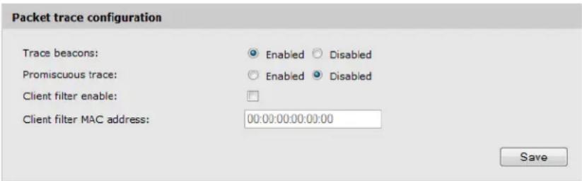
Trace beacons
Enable to trace the 802.11 beacons detected or transmitted by the radio. It is recommended that you also enable Promiscuous trace when performing a beacon trace.
Promiscuous trace
Enable to place the radio in promiscuous mode when the trace is active.
In promiscuous mode, the radio receives all traffic on the channel, including traffic that is not destined to the M220. While the radio is operating in promiscuous mode, it continues serving associated clients. Packets not destined to the AP are not forwarded.
As soon as the trace is completed, the radio reverts to non-promiscuous mode operation.
Client filter enable
Enable to use the WLAN client filter to trace only frames that are transmitted to, or received from, a WLAN client with a specified MAC address.
Client filter MAC address
Specify a MAC address for WLAN client filtering. Note that the MAC filter is active only when a trace is performed on an 802.11 interface.
Note
Changes to packet trace settings take effect after a packet trace is restarted. Modifying the parameters while a packet trace is running does not affect the current packet trace session. To begin using new parameter values, an existing packet trace session must be stopped and restarted.
Packet file trace
In packet file trace mode, the M220 stores captured packets in a file on the device.
Upon activation, the packet trace proceeds until one of the following occurs:
- The trace time reaches configured duration.
- The trace file reaches its maximum size. • The administrator stops the trace.
During the trace, you can monitor the trace status, elapsed trace time, and the current trace file size. You can select Refresh to update this information while the trace is in progress.
Performing a packet file trace
To perform a packet file trace.
- Select Tools > Network trace.

- Select a Trace interface. The following M220 interfaces are available for packet trace:
• radio1: 802.11 traffic on the radio. • eth0: 802.3 traffic on the Ethernet port. • wlan0: Traffic for the default wireless community. • wlan0vapx: Traffic for wireless community x, where x is the community ID and can be from 1 to 7. Wireless community IDs are shown in the first column of the Communities table on the Wireless > Communities page. • brtrunk: Traffic that is forwarded among different wireless communities, the Ethernet interface, and WDS interfaces.
• wlan0wdsx: Traffic for WDS interface x, where x is the WDS interface ID and can be from 1 to 4. Configured WDS interfaces are shown on the Wireless > WDS page.
- Specify the following parameters:
• Trace duration: The time duration in seconds for the trace (range 10 to 3600).
• Max trace file size: The maximum allowed size for the trace file in KB (range 64 to 4096).
If you change either of these values, you must select Save before initiating a trace.
- Select Start Trace.
The trace session will run for the specified duration. You can view the trace status in the File trace status section. Select Refresh to see updated trace time and file size values. You can also select Stop Trace to stop a trace before the specified duration has elapsed.
Remote packet trace
Remote packet trace enables you to specify a remote port as the destination for packet captures. This feature works in conjunction with the Wireshark network analyzer tool for Windows. A packet trace server runs on the M220 and sends the captured packets via a TCP connection to the Wireshark tool.
A Windows PC running Wireshark enables you to display, log, and analyze captured traffic.
When the remote trace mode is in use, the M220 does not store any captured data locally in its file system.
Setting up Wireshark sessions
You can trace up to five interfaces on the M220 at the same time. However, you must start a separate Wireshark session for each interface. You can configure the IP port number used for connecting Wireshark to the M220. The default port number is 2002. The system uses five consecutive port numbers starting with the configured port for the packet trace sessions.
If a firewall is installed between the Wireshark PC and the M220, these ports must be allowed to pass through the firewall. The firewall must also be configured to allow the Wireshark PC to initiate TCP connection to the M220.
To configure Wireshark to use the M220 as the source for captured packets, you must specify the remote interface in the Capture Options menu. For example, to trace packets on an M220 with IP address 192.168.1.10 on radio 1 using the default IP port, specify the following interface:
rpcap://192.168.1.10/radio1
To trace packets on the Ethernet interface of the M220 and on the default wireless community (wlan0) using IP port 58000, start two Wireshark sessions and specify the following interfaces:
rpcap://192.168.1.10:58000/eth0 rpcap://192.168.1.10:58000/wlan0
When you are capturing traffic on the radio interface, you can disable beacon trace, but other 802.11 control frames are still sent to Wireshark. You can set up a display filter to show only the following:
• Data frames in the trace • Traffic on specific BSSIDs • Traffic between two clients
Some examples of useful display filters are the following:
- Exclude beacons and ACK/RTS/CTS frames:
!(wlan.fc.type_subtype == 8 || wlan.fc.type == 1)
- Data frames only:
wlan.fc.type == 2
- Traffic on a specific BSSID:
wlan.bssid == 00:02:bc:00:17:d0
- All traffic to and from a specific client:
wlan.addr == 00:00:e8:4e:5f:8e
Performance and security considerations
In remote packet trace mode, traffic is sent to the PC running Wireshark via one of the network interfaces. Depending on where the Wireshark tool is located, the traffic can be sent on an Ethernet interface or one of the radios. To avoid a traffic flood caused by tracing the trace packets, the M220 automatically installs a trace filter to filter out all packets destined to the Wireshark application. For example, if the Wireshark IP port is configured to be 58000, then the following trace filter is automatically installed on the M220:
not port range 58000-58004
Enabling the packet trace feature impacts M220 performance and can create a security issue (unauthorized clients may be able to connect to the AP and trace user data). The M220 performance is negatively impacted even if there is no active Wireshark session with the AP. The performance is negatively impacted to a greater extent when packet trace is in progress.
Due to performance and security issues, the packet trace mode is not saved in nonvolatile memory on the M220. If the M220 resets, the trace mode is disabled and you must re-enable it to resume capturing traffic. Packet trace parameters (other than mode) are saved in nonvolatile memory.
To minimize any performance impact on the M220 while traffic trace is in progress, you should install trace filters to limit which traffic is sent to the Wireshark tool. When capturing 802.11 traffic, a large portion of the captured frames tend to be beacons (typically sent every 100 ms by all APs). Although Wireshark supports a display filter for beacon frames, it does not support a trace filter to prevent the M220 from forwarding captured beacon packets to the Wireshark tool. To reduce the performance impact of capturing the 802.11 beacons, you can disable the trace beacons mode.
The remote packet trace facility is a standard feature of the Wireshark tool for Windows.
Note
Remote packet trace is not standard on the Linux version of Wireshark. The Linux version does not work with the AP.
Wireshark is an open source tool and is available for free. It can be downloaded from www.wireshark.org.
Performing a remote packet trace
To perform a remote packet trace.
- Set up the Wireshark session as described in Setting up Wireshark sessions on page 99.
- On the M220 management tool, select Tools > Network trace.

- In the Remote packet trace section, specify the Remote trace port. Specify the remote port to use as the destination for packet captures. The range is 1 to 65530 and the default port is 2002. If you change this value, you must select Save prior to starting the remote trace.
- Select Start Remote Trace.
The trace session will run for the specified duration. You can view the trace status in the Packet trace status section. Select Refresh to see the updated trace time. You can also select Stop Trace to stop a trace before the specified duration has elapsed.
Packet trace status
This section enables you to view the status of the packet trace on the AP.

Current trace status
Whether a packet trace is running or is stopped.
Packet trace time
The elapsed trace time for a trace in progress.
Packet trace file size
The current trace file size.
Packet trace file download
This section enables you to download the trace file by TFTP to a configured TFTP server, or by HTTP(S) to a PC. A trace is automatically stopped when the trace file download command is triggered.
HTTP download
Select HTTP to download to your PC or a network location.

When you select Download, you will be able to browse to the desired location.
TFTP download
Select TFTP to download to a TFTP server.

TFTP server filename
The file will be saved to the TFTP server under this name and path.
Server IP
Enter the IP address of the TFTP server.
When you select Download, a progress bar displays to indicate download status.
Ping
The M220 supports ping functionality to enable basic diagnostics of network devices. To ping another device, select Tools > Ping.
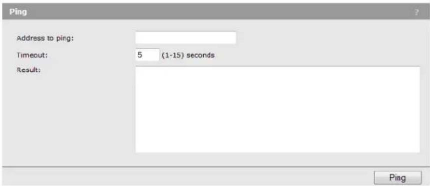
Address to ping
You can specify an IPv4 address, an IPv6 address, or a hostname.
Timeout
Specify the amount of time in seconds after which an unsuccessful ping will time out.
Results
The results window shows the size and number of each packet sent and, if the host is reached, the size and number of each packet received in response and its round-trip time. It also displays statistics about packet loss and, if the host is reached, the average round-trip time for all packets.
11 Support and other resources
Online Documentation
You can download documentation from the HP Support Website at: www.hp.com/networking/support. Search by product number or name.
Contacting HP
For worldwide technical support information, see the HP Support Website: www.hp.com/networking/support
Before contacting HP, collect the following information:
• Product model names and numbers • Technical support registration number (if applicable) • Product serial numbers - Error messages - Operating system type and revision level - Problem description and any detailed questions
HP Websites
For additional information, see the following HP Websites:
• www.hp.com/networking - www.hp.com
Conventions
The following conventions are used in this guide.
Management tool
This guide uses specific syntax when directing you to interact with the management tool user interface. Refer to the following image for identification of key user-interface elements and then the table below for example directions:

| Example directions in this guide What to do in the user interface | |
| Select Wireless > Radio. | Select Wireless on the main menu, and then select Radio on the sub-menu. |
| Set Mode to 5 GHz IEEE 802.11n. | For the Mode setting, select the 5 GHz IEEE 802.11n from the list. |
A Resetting to factory defaults
Factory reset procedures
To force the M220 into its factory default state, follow the procedures in this section.
Caution
Resetting the M220 to factory defaults deletes all configuration settings, resets the manager user name and password to admin, and enables the DHCP client on the Ethernet port. If no DHCP server assigns an address to the M220, its address defaults to 192.168.1.1.
Using the reset button
Using a tool such as a paper clip, press and hold the reset button for a few seconds until the status lights blink three times.
Using the management tool
To reset the M220 to factory defaults:
- Launch the management tool (default https://192.168.1.1).
- Select Maintenance > Config file management.
- Under Reset configuration, select Reset.
Reset
Restore the factory default configuration.
Reset

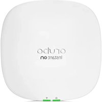

- HP M220 802.11N ACCESS POINT CONFIGURATION AND ADMINISTRATION GUIDE
- ACKNOWLEDGMENTS
- WARRANTY
- CONTENTS
- DEPLOYING THE M
- USING QUICK SETUP
- MANAGING THE M
- WORKING WITH WIRELESS COMMUNITIES AND AUTHENTICATION
- WIRELESS CONFIGURATION
- CREATING WDS LINKS
- CONFIGURING ETHERNET, IP, AND VLAN SETTINGS
- CLUSTERING MULTIPLE M220S
- MAINTENANCE
- TOOLS
- SUPPORT AND OTHER RESOURCES
- A RESETTING TO FACTORY DEFAULTS
- OVERVIEW
- AUTOMATICALLY RUNNING QUICK SETUP THE FIRST TIME YOU LOG IN
- BASIC WIRELESS NETWORK
- MULTIPLE WIRELESS NETWORKS
- MULTIPLE WIRELESS NETWORKS WITH WIRED VLANS
- MULTIPLE WIRELESS NETWORKS WITH RADIUS AUTHENTICATION
- ADD TO WIRELESS NETWORK WITH EXISTING AP CLUSTER
- ACCESSING QUICK SETUP AFTER YOUR FIRST LOGIN
- QUICK SETUP WIZARD
- STEP 1: SPECIFY ACCESS POINT SETTINGS
- CONFIGURE THE RADIO
- GET AN IP ADDRESS
- IPV4 ADDRESSES
- IPV6 ADDRESSES
- ENTERING A STATIC IPV6 ADDRESS
- ENABLING AUTO CONFIGURATION
- CHANGE ADMINISTRATOR LOGIN CREDENTIALS
- NOTE
- CURRENT PASSWORD
- NEW PASSWORD AND CONFIRM PASSWORD
- CAUTION
- STEP 2: SPECIFY ACCESS POINT CLUSTER SETTINGS
- CLUSTERING
- CLUSTER NAME
- CLUSTER LOCATION
- CLUSTERING IP VERSION
- STEP 3: SPECIFY WIRELESS NETWORK SETTINGS
- WIRELESS COMMUNITIES
- WIRELESS COMMUNITY SETTINGS
- IDENTIFY THE WIRELESS NETWORK
- NETWORK NAME (SSID)
- MAP WIRELESS NETWORK TO A VLAN
- VLAN ID
- SECURE THE WIRELESS NETWORK
- SECURITY METHOD
- SECURITY METHODS
- WPA/WPA2 PERSONAL
- WPA VERSIONS
- KEY
- X/DYNAMIC WEP
- RADIUS IP ADDRESS TYPE
- RADIUS IP OR IPV6 ADDRESS
- RADIUS KEY
- WPA/WPA2 ENTERPRISE
- STATIC WEP
- KEY LENGTH
- KEY TYPE
- QUICK SETUP GLOBAL SETTINGS PAGE
- SYSTEM SETTINGS
- MULTIPLE RADIUS SERVERS
- SYSTEM SUMMARY
- IP ADDRESS
- STATIC IPV6 ADDRESS
- IPV6 AUTOCONFIGURED GLOBAL ADDRESSES
- IPV6 LINK LOCAL ADDRESS
- MAC ADDRESS
- SOFTWARE VERSION
- PRODUCT IDENTIFIER
- HARDWARE VERSION
- SERIAL NUMBER
- DEVICE DESCRIPTION
- CONFIGURING WEB SERVER SETTINGS
- HTTPS SERVER STATUS
- HTTP SERVER STATUS
- HTTP PORT
- SESSION TIMEOUT
- SNMP CONFIGURATION
- SNMP
- READ-ONLY COMMUNITY NAME
- CONFIRM READ-ONLY COMMUNITY NAME
- SUPPORTED MIBS
- STANDARD MIBS
- PRIVATE MIBS
- SYSTEM TIME
- SET SYSTEM TIME
- MANUALLY
- USING NETWORK TIME PROTOCOL (NTP)
- DAYLIGHT SAVINGS
- CONFIGURING GLOBAL RADIUS SERVERS
- RADIUS IP ADDRESS
- ENABLE RADIUS ACCOUNTING
- MANAGING WIRELESS COMMUNITIES
- ABOUT THE DEFAULT WIRELESS COMMUNITY
- WIRELESS COMMUNITY CONFIGURATION OPTIONS
- BROADCAST SSID
- MAC AUTHENTICATION
- WIRELESS PROTECTION
- TRANSFER KEY INDEX
- KEY 1 TO KEY
- AUTHENTICATION
- USE GLOBAL RADIUS SERVER
- RADIUS IP ADDRESS/RADIUS IPV6 ADDRESS
- RADIUS IP OR IPV6 ADDRESS 1 TO
- RADIUS KEY 1 TO
- BROADCAST KEY REFRESH RATE
- SESSION KEY REFRESH RATE
- WPA PERSONAL
- WPA ENTERPRISE
- ENABLE PRE-AUTHENTICATION
- RADIUS SERVER-BASED MAC AUTHENTICATION
- LOCAL MAC AUTHENTICATION
- FILTER
- STATIONS LIST
- WIRELESS COVERAGE
- FACTORS LIMITING WIRELESS COVERAGE
- INTERFERENCE
- PHYSICAL CHARACTERISTICS OF THE LOCATION
- CONFIGURING OVERLAPPING WIRELESS APS
- PERFORMANCE DEGRADATION AND CHANNEL SEPARATION
- SELECTING CHANNELS
- SAMPLE CHANNEL SELECTIONS
- N BEST PRACTICES
- SUPPORTING LEGACY WIRELESS CLIENTS
- COMPATIBILITY MODES
- IEEE 802.11N (5 GHZ) AND IEEE 802.11N (2.4 GHZ)
- CHANNEL WIDTH
- RADIO CONFIGURATION
- COUNTRY
- BASIC SETTINGS
- RADIO
- MODE
- CHANNEL
- CHANNEL BANDWIDTH
- PRIMARY CHANNEL (802.11N MODES ONLY)
- CURRENT CHANNEL
- STATION ISOLATION
- ADVANCED RADIO SETTINGS
- MULTIDOMAIN REGULATORY MODE
- SHORT GUARD INTERVAL SUPPORTED
- STBC MODE
- PROTECTION
- BEACON INTERVAL
- DTIM PERIOD
- FRAGMENTATION THRESHOLD
- RTS THRESHOLD
- TRANSMIT POWER
- FIXED MULTICAST RATE
- BCAST/MCAST RATE LIMITING
- RATE LIMIT
- RATE LIMIT BURST
- DETECTING ROGUE APS
- ENABLING SCANNING
- DETECTED AND KNOWN AP LISTS
- WORKING WITH SAVED AP LISTS
- VIEWING WIRELESS INFORMATION
- VIEWING ALL CONNECTED WIRELESS CLIENTS
- VIEWING WIRELESS STATISTICS FOR THE RADIO
- KEY CONCEPTS
- SIMULTANEOUS AP AND WDS SUPPORT
- USING THE 5 GHZ BAND FOR WDS LINKS
- CONFIGURATION CONSIDERATIONS
- WDS CONFIGURATION
- GENERAL
- LOCAL ADDRESS
- SPANNING TREE MODE
- WDS LINK
- REMOTE ADDRESS
- ENCRYPTION
- SAMPLE WDS DEPLOYMENT
- OBTAIN THE MAC ADDRESS OF M
- SET UP THE WDS LINK ON M
- SETUP THE WDS LINK ON M
- TEST THE LINK AND MAKE PERFORMANCE ADJUSTMENTS
- ETHERNET CONFIGURATION
- MANAGEMENT VLAN ID
- UNTAGGED VLAN
- UNTAGGED VLAN ID
- IPV4 CONFIGURATION
- AUTOMATICALLY ASSIGNING AN IP ADDRESS (DEFAULT METHOD)
- STATIC IP CONFIGURATION
- CONNECTION TYPE
- SUBNET MASK
- DEFAULT GATEWAY
- DNS NAMESERVERS
- IPV6 CONFIGURATION
- IPV
- STATIC IPV6 ADDRESS PREFIX LENGTH
- DEFAULT IPV6 GATEWAY
- STATIC IPV6 ADDRESS STATUS
- IPV6 AUTO CONFIGURATION
- VLAN CONFIGURATION
- VLAN ASSIGNMENT VIA WIRELESS COMMUNITIES
- VLAN ASSIGNMENT VIA RADIUS
- EXAMPLE
- EMPLOYEE WIRELESS COMMUNITY
- GUEST WIRELESS COMMUNITY
- PORT STATISTICS
- PORT
- PACKETS
- DROPPED
- ERRORS
- SHARED SETTINGS IN A CLUSTER
- SETTINGS THAT ARE SHARED/NOT SHARED BY THE CLUSTER
- IPV4 AND IPV6 CLUSTERS
- CLUSTER FORMATION
- CLUSTER CRITERIA
- CLUSTER NEGOTIATION
- CREATING A CLUSTER
- REMOVING AN AP FROM THE CLUSTER
- CLIENT CONNECTIONS
- AP MAC
- STATION MAC
- IDLE
- RATE (MBPS)
- SIGNAL
- RX TOTAL
- TX TOTAL
- ERROR RATE
- CHANNEL PLANNING
- CONFIGURATION
- CHANNEL CHANGE INTERVAL
- INTERFERENCE THRESHOLD
- LAST PROPOSED CHANNELS APPLIED
- CURRENT CHANNEL ASSIGNMENTS
- BAND
- PROPOSED CHANNEL
- STATUS
- LOCKED
- CONFIGURATION FILE MANAGEMENT
- RESET
- SAVE
- RESTORE
- REBOOT
- SOFTWARE UPDATES
- SOFTWARE INFORMATION
- SOFTWARE UPGRADE
- SYSTEM INFORMATION
- SYSTEM LOG
- SYSTEM LOG CONFIGURATION
- PERSISTENCE
- SEVERITY
- DEPTH
- REMOTE SYSLOG CONFIGURATION
- REMOTE SYSLOG
- SYSLOG SERVER
- SYSLOG PORT
- EVENTS
- EMAIL ALERT
- GENERAL CONFIGURATION
- FROM ADDRESS
- URGENT MESSAGE SEVERITY
- NON-URGENT SEVERITY
- NON URGENT LOG DURATION
- MAIL SERVER CONFIGURATION
- MAIL SERVER
- MAIL SERVER ADDRESS
- MAIL SERVER SECURITY
- MAIL SERVER PORT
- USERNAME
- PASSWORD
- MESSAGE CONFIGURATION
- MESSAGE
- TO ADDRESS
- EMAIL SUBJECT
- SENDING A TEST MESSAGE
- VIEWING EMAIL ALERT STATUS
- EMAIL ALERT STATUS
- NUMBER OF EMAILS SENT
- NUMBER OF EMAILS FAILED
- TIME SINCE LAST EMAIL SENT
- NETWORK TRACE CONFIGURATION
- PACKET TRACE CONFIGURATION
- TRACE BEACONS
- PROMISCUOUS TRACE
- CLIENT FILTER ENABLE
- CLIENT FILTER MAC ADDRESS
- PACKET FILE TRACE
- PERFORMING A PACKET FILE TRACE
- REMOTE PACKET TRACE
- SETTING UP WIRESHARK SESSIONS
- PERFORMANCE AND SECURITY CONSIDERATIONS
- PERFORMING A REMOTE PACKET TRACE
- PACKET TRACE STATUS
- CURRENT TRACE STATUS
- PACKET TRACE TIME
- PACKET TRACE FILE SIZE
- PACKET TRACE FILE DOWNLOAD
- HTTP DOWNLOAD
- TFTP DOWNLOAD
- TFTP SERVER FILENAME
- SERVER IP
- PING
- ADDRESS TO PING
- TIMEOUT
- RESULTS
- ONLINE DOCUMENTATION
- CONTACTING HP
- HP WEBSITES
- CONVENTIONS
- MANAGEMENT TOOL
- FACTORY RESET PROCEDURES
- USING THE RESET BUTTON
- USING THE MANAGEMENT TOOL
Brand : HP
Model : OfficeConnect M220
Category : Access Point