USER MANUAL TLS-9924P SANYO
Please read this manual carefully before connecting your VCR and operating it for the first time.
Be sure to read carefully and follow all the PRECAUTIONS on page 1 and 2.
Keep the manual in a safe place for future reference.
PRECAUTIONS
WARNING: DO NOT EXPOSE THE VCR TO DRIPPING OR SPLASHING, AND NEVER PUT ANY OBJECTS FILLED WITH LIQUIDS, SUCH AS VASES, ON TOP OF THE VCR. To avoid electrical shock, do not open the cabinet. Refer servicing to qualified personnel only. If the power supply cord (AC power cord) of this appliance is damaged, it must be replaced. Return to a SANYO Authorised Service Centre for replacement of the cord.
CAUTION: Do not put your hand or other objects in the cassette loading slot because of risk of injury or accident. Be sure to keep small children away from the VCR.
Danger of explosion if battery is incorrectly replaced.
Replace only with the same or equivalent type recommended by the manufacturer.
Discard used batteries according to the manufacturer's instructions.
IMPORTANT NOTE (U. K. Only)
The wires in the mains lead are coloured according to the following code:
Blue:
Neutral
Brown:
Live
If the colours of the wires in the mains lead of this apparatus do not correspond with the colour markings identifying the terminals in your plug, proceed as follows:
- The wire which is coloured blue must be connected to the terminal which is marked with the letter N or coloured blue or black.
- The wire which is coloured brown must be connected to the terminal which is marked with the letter L or coloured brown or red.
- Do not connect either wire to the Earth terminal.
ADVARSEL!
For safe operation and satisfactory performance of your VCR, keep the following in mind when selecting a place for its installation:
- Shield it from direct sunlight and keep it away from sources of intense heat.
- Avoid dusty or humid places.
- Avoid places with insufficient ventilation for proper heat dissipation. Do not block the ventilation holes of the VCR. Do not place the unit on a carpet because this will block the ventilation holes.
- Install the VCR in a horizontal position only.
- Avoid locations subject to strong vibrations.
- Avoid moving the VCR between cold and hot locations (see "Moisture Condensation Problems", this page).
- Do not place the VCR directly on top of the TV, as this may cause playback or recording problems.
Avoiding Electrical Shock and Fire
- Do not handle the power cord with wet hands.
- Do not pull on the power cord when disconnecting it from an AC wall outlet. Grasp it by the plug.
- If any liquid is spilled on the VCR, unplug the power cord immediately and have the unit inspected at a factory-authorized service centre.
- Do not place anything directly on top of this VCR.
Moisture Condensation Problems
Cause:
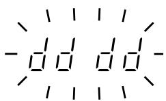
When the VCR is first installed, moved from a cold area to a warm area or placed in a location with high humidity, dew (moisture) may form in the unit. The Dew indicator (ddd) blinks. If you operate the VCR with dew inside, damage may result.
Prevention:
1 Do not operate the VCR for approximately 2 hours.
When the VCR reaches room temperature, the Dew indicator (dddd) will turn off and the VCR will be ready for operation.
Power on/stand-by mode
The power on/stand-by mode is selected by pressing the STANDBY/ON button.
VCR display
Stand-by mode
Power on mode


"Stand-by mode" is the condition in which only the time is displayed.
Do not forget that even in the stand-by mode there is an electrical voltage inside the VCR as long as it is connected to a wall socket.
Disconnect the power cord from the wall socket if the VCR is not to be used for a long time.
CONTENTS
PRECAUTIONS 1
FEATURES. 3
ACCESSIONS 3
LOCATIONS OF CONTROLS AND INDICATORS . . . 4
CONNECTIONS 8
ON-SCREEN MENU. 9
SETTING THE LANGUAGE AND CLOCK. 11
SUPERIMPOSE DISPLAY 13
VIDEO CASSETTE TAPES 14
TAPE MANAGEMENT 16
NORMAL RECORDING 19
AUTOREPEAT RECORDING 23
ALARM RECORDING 24
PROGRAMME TIMER RECORDING 27
RECORDING USING AN EXTERNAL TIMER INPUT. 31
SERIES RECORDING 32
SINGLE IMAGE RECORDING. 33
NORMAL PLAYBACK 34
SPECIAL PLAYBACK 35
DAY/TIME SEARCH. 37
TAPE COUNTER 37
SECURITY LOCK. 38
CLOCK ADJUSTMENT 39
SELECTING INPUT AND OUTPUT TERMINALS....39
SETTING THE CASSETTE EJECT MODE 40
SYNCHRONIZATION CONTROL 41
SETTING FOR RS-485 OR RS-232C USE 43
CHECKING POWER FAILURE, FAILURE DUE TO CONDENSATION AND USAGE DURATION 44
OUTPUT TERMINALS 45
HEAD SWITCHING FUNCTION. 49
MAINTENANCE 50
TROUBLESHOOTING GUIDE 52
SPECIFICATIONS 53
FEATURES
- Tape management function
JOG/SHUTTLE operation
Clog detection
High-speed Fast Forward/Rewind
- Field recording/playback
- Audio recording is available in 3-, 12- and 24-hour modes (E-180)
- Autorepeat recording
- Series recording function
- Alarm recording function
- Single image recording function
- On-screen mode setting
- Integrated time date generator
Day/Time search function
- Alarm scan/search function
- Forward/Reverse field advance function
- 30-day memory backup
Security lock
- Recording check function
Automatic head cleaning function
- Thread check function
- Head switching function
Synchronization control function
TLS-1960P only
- 3, 12, 24, 48, 72, 96, 120, 168, 240, 360, 480, 720 and 960-hour mode recording (E-180)
- AC or DC power operation.
TLS-9924P only
3, 12 and 24-hour mode recording (E-180)
When using the RS-485/232C interface board (VZU-485/232C), the VCR can be controlled from a computer or a system controller.
ACCESSIONS
① Power cord
② Holder
LOCATIONS OF CONTROLS AND INDICATORS
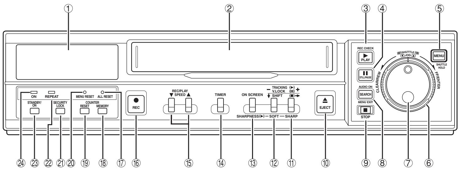
Front Panel
① Digital display panel
② Cassette loading slot
③ PLAY button
REC CHECK button
(4) STILL/PAUSE button
(5) MENU button
SHUTTLE HOLD button
(6) SHUTTLE ring
⑦ JOG dial
SEARCH button
MENU EXIT button
AUDIO ON button
STOP button
EJECT button
⑪ TRACKING + button
V. LOCK + button
SHIFT → button
SHARP button
⑫ TRACKING - button
V. LOCK - button
SHIFT ↓ button
SOFT button
⑬ ON SCREEN button SHARPNESS button
⑭ TIMER button
⑤ REC/PLAY SPEED ▲,▼ (decrease or increase recording/playback speed mode) button
REC (record) button
(17) ALL RESET button
COUNTER MEMORY button
19 COUNTER RESET button
20 MENU RESET button
② SECURITY LOCK button
22 REPEAT (autorepeat recording) indicator
23 STANDBY/ON button
24 ON (power on) indicator
NOTE:
- Buttons ⑪, ⑫ and ⑮ are also used for menu setting.
LOCATIONS OF CONTROLS AND INDICATORS
Digital Display
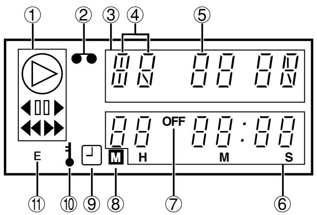
① Operation Indicators
- They display the actual operation mode.
| Operation Mode | Indicator |
| Record (REC) | ○ |
| Record pause (REC PAUSE) | ○+ -□□- |
| Playback (PLAY) | ▷ |
| Still image ( STILL) | ▷+ -□□- |
| Fast forward (FF) | ▷ |
| Rewind (REW) | ◁ |
| Forward picture search | ▷+ ▷ |
| Reverse picture search | ▷+ △ |
| Reverse playback | ▷+ -□- |
| Forward field advance | ▷+ [□] + ▲ |
| Reverse field advance | ▷+ [□] + △ |
- Clog detection indicator
- Flashes when the recording quality deteriorates due to dirty VCR heads.
② Cassette indicator
Lights when a cassette is loaded.
(3) Mode display
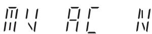
M flashes: Problem with mechanism.
V flashes: Video loss has occurred.
A flashes: Alarm recording in progress.
When alarm recording finishes, AL lights at ④.
If you press the STOP button during alarm recording, AL flashes at ④.
C flashes: Clog detection has occurred.
N flashes: Mode changed to non-recording mode while recording was in progress.
NOTES:
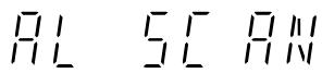
- Alarm scan setting display
- Dew display
- Picture control setting display
- 4 digit security lock setting display
- Tracking control display


LOCATIONS OF CONTROLS AND INDICATORS
[With the RS-485/232C interface board]
- Display when set to RS-485
![SANYO TLS-9924P - [With the RS-485/232C interface board] - 1](/content/2019/10/13413/images/37729cac8d56ef53640450e0a1259b5945459680c3c5bc75298eb639ec15f531.jpg)
- Display when set to RS-232C
![SANYO TLS-9924P - [With the RS-485/232C interface board] - 2](/content/2019/10/13413/images/1c4c1cfc9fbfb0c246fb5701991a46f42ad61d863cd7bac38a8b3aebf120a3a1.jpg)
Data transfer speed setting display
![SANYO TLS-9924P - [With the RS-485/232C interface board] - 3](/content/2019/10/13413/images/91cf6195d3d84e0fe2e31b5d37e1b6a06e1d7e8d405490534785626961368b31.jpg)
![SANYO TLS-9924P - [With the RS-485/232C interface board] - 4](/content/2019/10/13413/images/5e97770815955007094b8931ca5f7f7c163e6acb2f671d054c44c1d0b312f27b.jpg)
- Address setting display (RS-485 only)
![SANYO TLS-9924P - [With the RS-485/232C interface board] - 5](/content/2019/10/13413/images/530fa8ddb67211d3bcfbc79f2ebb9845cea4e831e7a3f981aab9dd473a2f9c59.jpg)
③, ⑥ Mode display
Day/Time search setting display
![SANYO TLS-9924P - [With the RS-485/232C interface board] - 6](/content/2019/10/13413/images/41cb366f912ea4ad927e2d36324d5ecca47ceeaa1f760cd0c2826d672b698aef.jpg)
⑤ Power failure indicator Lights after a power failure.
NOTE:
- To cancel the "P" display, press the MENU RESET button.
(6) Counter display
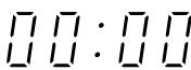
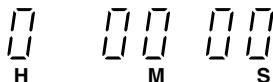
- Linear time counter display (Tape inserted)
⑦ OFF indicator
Lights when the tape end has been reached after recording.
LOCATIONS OF CONTROLS AND INDICATORS
Back Panel (With the RS-485/232C interface board)
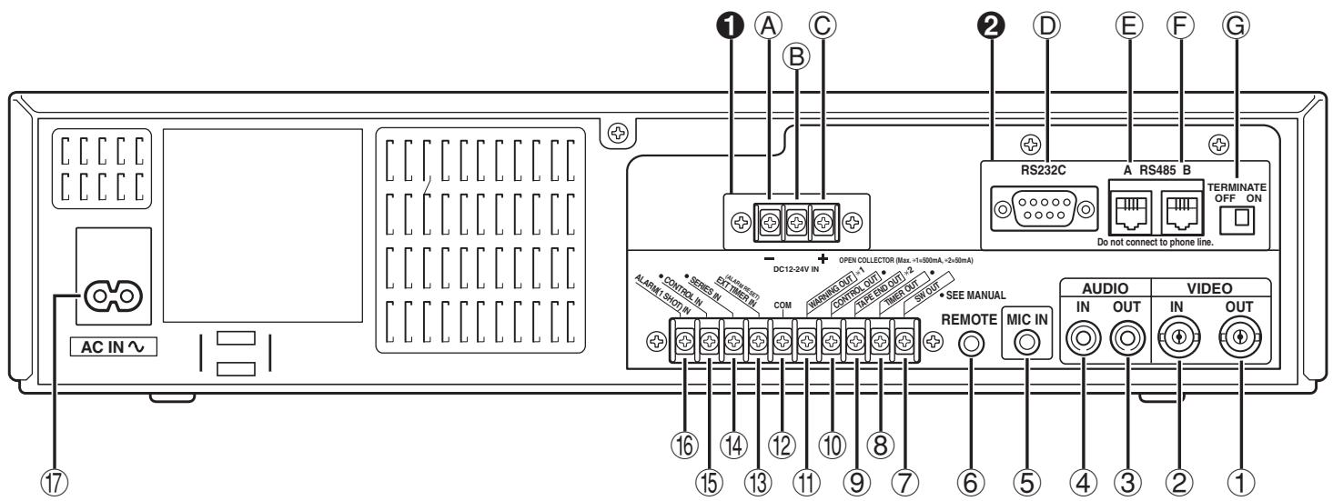
①VIDEO OUT (video output) jack
②VIDEO IN (video input) jack
(3) AUDIO OUT (audio output) jack
④ AUDIO IN (audio input) jack
⑤ MIC IN (microphone input) jack
(6) REMOTE (remote control input) jack
SW OUT (switch output) terminal
⑧ TIMER OUT (timer recording output) terminal
9 TAPE END OUT (tape end output) terminal
10 CONTROL OUT terminal
(1) WARNING OUT (warning output) terminal
- Signals are output when an alarm, clog detection, video loss, non-recording or mechanism problem occurs.
12 COM (common) terminal
⑬ EXT TIMER IN (external timer trigger input) terminal
ALARM REST IN (alarm recording reset input)
terminal
14 SERIES IN (series recording trigger input) terminal
15 CONTROL IN terminal
16 ALARM IN (alarm trigger input) terminal 1 SHOT IN (single image recording trigger input) terminal
⑰ AC power input
DC power input (TLS-1960P only)
A DC12-24V IN "input terminal
B Do not use
DC12-24V IN “+” input terminal
RS-485/232C interface board (sold separately)
RS-232C connector (D-sub 9-pin type)
RS-485 A connector (RJ-11)
RS-485 B connector (RJ-11)
G TERMINATE switch
NOTES:
- The above illustration shows the unit when the RS-485/232C interface board is installed. If no RS-485/232C interface board is installed, connectors and switches through to do not appear.
- The terminal may be damaged by a torque of 0.49 N·m (5kg·cm) or more and by using screwdriver with a tip with a diameter of 6 mm or more.
- Do not connect the RS-485 A and RS-485 B connectors to a phone line.
- The ⑧ , ⑩ , ⑭ and ⑤ terminals can be used to select the input and output signals. (Refer to “SELECTING INPUT AND OUTPUT TERMINALS” on page 39.)
- If using the ⑩ and ⑮ terminals, multiple VCRs can be operated by operating a single VCR. (Refer to "SYNCHRONIZATION CONTROL" on page 41.)
- Pay attention to the polarity of the DC12-24V input terminal ("+": red screw, "−": black screw).
CONNECTIONS
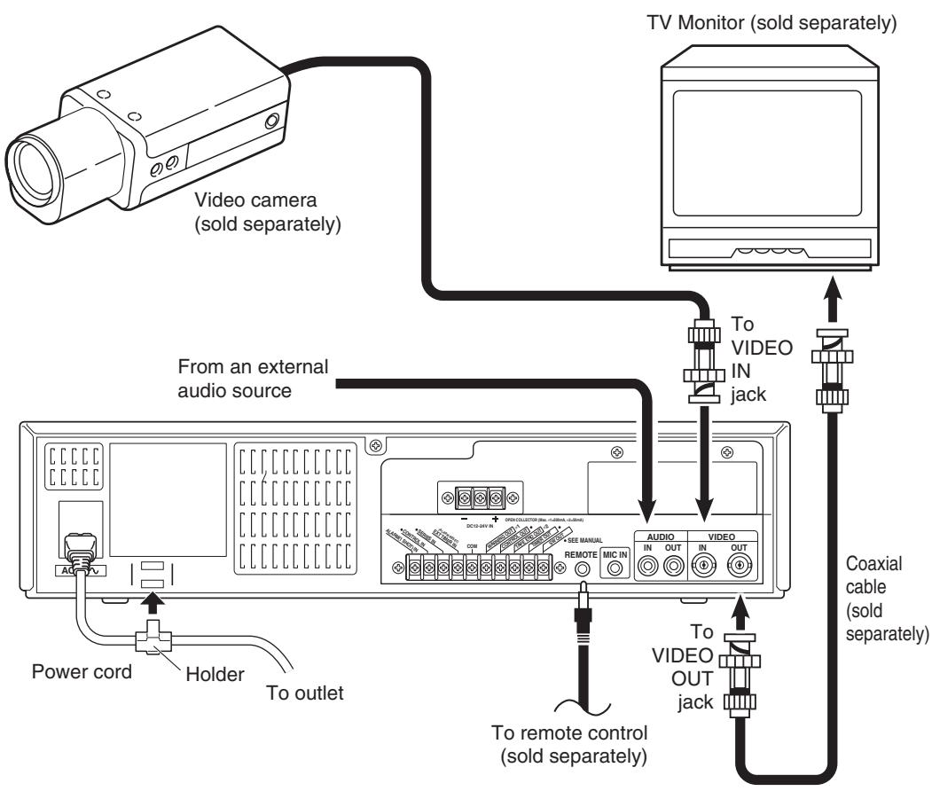
Connect the video camera and TV monitor as shown in the figure below.
NOTE: Before making the connections, make sure the devices are disconnected from the power outlet.
Power Cord Installation
Plug the power cord (supplied) into the AC power input (AC IN ) on the VCR back panel. Insert the plug straight and firmly.
Insert the AC power cord into the holder.
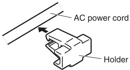
Fix the holder to the VCR back panel.
NOTES:
- For more details, please refer to the manuals accompanying all other devices. If the connections are not made properly, it may cause a fire or damage the equipment.
- You can use a VA-RMN01 Remote Control Unit (sold separately) to control the VCR remotely.
- If there is no video signal when the power is turned on, "NO VIDEO" will be displayed on-screen.
NOTES (TLS-1960P only):
- Use a DC power cord rated A.W.G 18 (1.25 mm²) or more.
- The table below indicates the DC power source output and DC power maximum cord lengths.
| DC power source output | DC power maximum cord lengths |
| 18 V or more 2 A | 6 m |
| 12 ~ 16 V 3 A | 6 m |
Main Menu
To access on-screen menu
1 Press the STANDBY/ON button.
When no menu is displayed on-screen, press the MENU button.
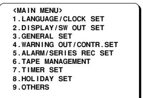
MAIN MENU
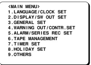
Press the MENU EXIT (or MENU) button to return to the monitor screen.
Using the JOG dial and SHUTTLE ring for settings
JOG dial
Put the tip of your index finger into the depression, then turn the dial in any direction.
- When the display is highlighted in a sub-menu, turn the dial to select the setting item.
- When the display is highlighted in a MAIN MENU, select a sub-menu.
- While the display is flashing, turn the dial and the selected data setting will change or the selected setting value will increase or decrease.
SHUTTLE ring
- When a menu is being displayed, turn the ring 10° or more clockwise to change the selected setting item from highlighted to flashing.
- After making the setting, turn the ring clockwise to save the setting and move to the next setting.
- When a MAIN MENU is being displayed, turn the ring clockwise and the sub-menu for selection will appear.
- When a sub-menu is being displayed, turn the ring counterclockwise and the MAIN MENU will appear.
- If there are several items on one line, turn the ring clockwise to move to the next item (on the right) and confirm the setting. Turning the ring counterclockwise will restore the original setting condition and move to the previous item (on the left).
To enter or modify settings within a sub-menu
When a MAIN MENU is being displayed, turn the JOG dial to select one of the sub-menus, then turn the SHUTTLE ring clockwise.
- The selected sub-menu appears.
Turn the JOG dial to move the selection to the desired setting, then turn the SHUTTLE ring clockwise.
- The selected item flashes.
③ Turn the JOG dial to enter or modify the setting.
4 Press the MENU EXIT button to save the settings and return to the monitor screen.
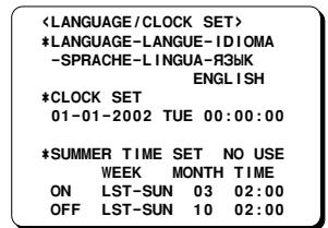
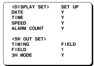
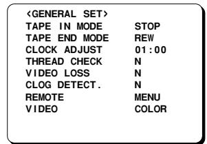
| <WARNING OUT SET>SET UP |
| ALARM | Y |
| NON REC | N |
| MECHA.PROBLEM | Y |
| VIDEO LOSS | Y |
| CLOG DETECT. | Y |
| <CONTROL SET> |
| EJECT MODE | EJECT1 |
| OPERATION | SLAVE |
NOTES:
- The "VIDEO LOSS" line does not appear if "VIDEO LOSS" is set to "N" in the (GENERAL SET) menu.
- The "CLOG DETECT." line does not appear if "CLOG DETECT." is set to "N" in the (GENERAL SET) menu.
| <ALARM/SERIES REC SET> |
| *ALARM SET |
| MODE | Y1 |
| SPEED | 3H |
| DURATION | 20S |
| *1 SHOT SET |
| FIELD | 1 |
| INTERVAL | 1M |
| *SERIES REC | N |
| *TAPE END OUT | 3:00 |
| <TAPE MANAGEMENT> |
| *TAPE MANAGEMENT | N |
| *PROTECT DAY | 30 |
| *REC PASS SET | 10 |
| *GROUP NO. SET | OFF |
| *OVERRIDE | N |
| <TIMER SET> |
| WEEK | START | STOP | SPD |
| SUN | ---- | ---- | --- N |
| MON | ---- | ---- | --- N |
| TUE | ---- | ---- | --- N |
| WED | ---- | ---- | --- N |
| THU | ---- | ---- | --- N |
| FRI | ---- | ---- | --- N |
| SAT | ---- | ---- | --- N |
| DAILY | ---- | ---- | --- N |
| EXT | ********** | ********** | --- N |
| (Holiday SET) |
| 1 | 11 | |
| 2 | 12 | |
| 3 | 13 | |
| 4 | 14 | |
| 5 | 15 | |
| 6 | 16 | |
| 7 | 17 | |
| 8 | 18 | |
| 9 | 19 | |
| 10 | 20 | |
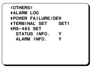
NOTE:
- This is the display when the RS-485/232C interface board is installed. The last three lines will not appear if this board is not installed.
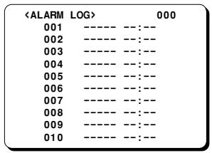
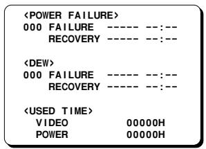
NOTES:
- Setting items are highlighted (appear in blue characters) when they are selected.
- Settings flash while they are being changed.
- When a menu is displayed, recording will not be possible.
- During recording or playback the menus cannot be displayed.
- To reset the settings of a menu to their original values, select the desired menu and then press the MENU RESET button.
- The USED TIME data in the (POWER FAILURE/DEW/USED TIME) menu cannot be cleared even when the MENU RESET button is pressed.
- Press the MENU button to save any settings made and switch menu screens. To display the (ALARM LOG) menu or (POWER FAILURE/DEW/USED TIME) menu, select the "ALARM LOG" or "POWER FAILURE/DEW" line in the (OTHERS) menu and then turn the SHUTTLE ring clockwise.
- Turn the SHUTTLE ring counterclockwise while a setting item is highlighted (appears in blue characters) to return to the main menu. In the case of the (ALARM LOG) menu or the (POWER FAILURE/DEW/USED TIME) menu, to return to the (OTHERS) menu.
English
SETTING THE LANGUAGE AND CLOCK
Language Setting
English, French, Spanish, Portuguese, German, Italian or Russian can be selected by the user.
1 Turn the power on to all devices used.
Press the MENU button to display the MAIN MENU.
- The "1.LANGUAGE/CLOCK SET" line appears highlighted.
③ Turn the SHUTTLE ring clockwise.
O The (LANGUAGE/CLOCK SET) menu appears.
○ "ENGLISH" is highlighted (appears in blue characters).
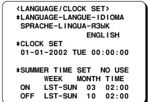
4 Turn the SHUTTLE ring clockwise.
- The display colour for the selected item returns to the original colour and flashes.
⑤ Turn the JOG dial to select the language of your choice.
- To set the next item, turn the SHUTTLE ring clockwise, then turn the JOG dial to select the next setting.
When finished, press the MENU EXIT button to return to the monitor screen.
Clock setting
Example: To set the clock to October 15, 2002 at 3:20 PM (15:20).
1 Follow steps 1 to 3 under "Language Setting".
Turn the JOG dial until the "CLOCK SET" setting is highlighted (appears in blue characters).
③ Turn the SHUTTLE ring clockwise.
The day position starts flashing.
4 Turn the JOG dial to set the day (15), then turn the SHUTTLE ring clockwise.
The day of week is set automatically.
⑤ Turn the JOG dial to set the month (10), then turn the SHUTTLE ring clockwise.
⑥ Turn the JOG dial to set the year (2002), then turn the SHUTTLE ring clockwise.
7 Turn the JOG dial to set the hours (15 for 3 PM), then turn the SHUTTLE ring clockwise.
- Unit uses 24hours format.
⑧ Turn the JOG dial to set the minutes (20), then turn the SHUTTLE ring clockwise.
*LANGUAGE-LANGUPE-TD TOMA
-SPRACHE-LINGUA-H3Bk ENGL+CGI
*CLKSET
15-10-2002TUE15:20:00
10 10 2002 102 20.00
- If a wrong setting has been entered, turn the SHUTTLE ring counterclockwise to move to the setting to be changed, then turn the JOG dial to enter the correct setting.
For accurate clock setting, turn the JOG dial counterclockwise timed with a time broadcast or other accurate time signal. This will start the seconds counting from 00.
- To set the next item, turn the SHUTTLE ring clockwise, then turn the JOG dial to select the next setting.
Press the MENU EXIT button to return to the monitor screen.
NOTE:
- In STOP mode, press and hold the STOP button then press the TRACKING - button to reset the minutes and seconds to 00 (to the closest hour). For example, between 13:30:00 and 14:29:59 the clock is reset to 14:00:00.
SETTING THE LANGUAGE AND CLOCK
Automatic Summer Time Adjustment
1 Follow steps 1 to 3 under "Language Setting" on page 11.
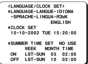
② Turn the JOG dial until the "SUMMER TIME SET" setting is highlighted (appears in blue characters), then turn the SHUTTLE ring clockwise.
③ Turn the JOG dial to set the auto summer time/standard time adjustment, then turn the SHUTTLE ring clockwise.
NO USE. No summer time/standard time adjustment is made.
USE The auto summer time/standard time adjustment is made.
° If using the "USE" setting, continue with steps 4 to 7.
4 Turn the JOG dial to select the "ON" line setting, then turn the SHUTTLE ring clockwise.
° The "LST" of the "ON" line flashes.
Set the day the summer time adjustment is made.
- Turn the JOG dial to set the week, then turn the SHUTTLE ring clockwise. 1ST, 2ND, 3RD, 4TH or LST (first, second, third fourth or last)
- Turn the JOG dial to set the day of week, then turn the SHUTTLE ring clockwise. SUN, MON, TUE, .... SAT (Sunday, Monday, Tuesday....Saturday)
- Turn the JOG dial to set the month the summer time adjustment is made, then turn the SHUTTLE ring clockwise.
01, 02,...11, 12 (for January, February....November, December)
- Turn the JOG dial to set the time (hour) the summer time adjustment is made, then turn the SHUTTLE ring clockwise.
- Turn the JOG dial to set the time (minutes) the summer time adjustment is made, then turn the SHUTTLE ring clockwise.
⑥ Turn the JOG dial to select the "OFF" line setting, then turn the SHUTTLE ring clockwise.
○ The "LST" of the "OFF" line flashes.
7 Following the same procedure as above (step 5), set when the time is changed back from summer time to standard time.
Press the MENU EXIT button.
Factory setting:
WEEK MONTH TIME
ON LST-SUN 03 02:00 (AM)
OFF LST-SUN 10 02:00 (AM)

SUPERIMPOSE DISPLAY
Selecting the Superimpose Display
You can select to display or not the date, time, tape speed mode and number of alarm recordings.
1 Turn the power on to all devices used.
2 Press the MENU button to display the MAIN MENU.
③ Turn the JOG dial to select the "2.DISPLAY/SW OUT SET" line, then turn the SHUTTLE ring clockwise.
° The (DISPLAY/SW OUT SET) menu appears.
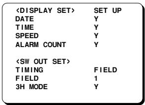
4 Turn the SHUTTLE ring clockwise.
⑤ Turn the JOG dial to select the desired mode, then turn the SHUTTLE ring clockwise.
SET UP . Set each item (Individual)
ALL Y. To set all items to "Y"
ALL N. To set all items to "N"
° If using the "SET UP" setting, continue with steps 6 to 8.
⑥ Turn the JOG dial until the item to be changed is highlighted, then turn the SHUTTLE ring clockwise.
7 Turn the JOG dial to set "Y" (displayed) or "N" (not displayed), then turn the SHUTTLE ring clockwise.
DATE. The date appears
TIME. The time appears
SPEED. The recording / playback
speed mode appears
ALARM COUNT. The number of alarm
recordings appears
Repeat steps 6 and 7 when setting other items.
When finished, press the MENU EXIT button.
NOTE:
- When the ON SCREEN button is pressed and the display appears, the items for which "Y" have been set are recorded. The items for which "N" was set at step ⑦ above are not recorded.
Changing the Superimpose Display Position
1 Turn the power on to all input devices to the VCR.
° The superimpose display appears.
- If the superimpose display does not appear, press the ON SCREEN button. The display will be turned on and off alternately each time the ON SCREEN button is pressed.
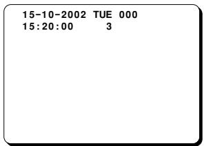
To change the display position, press the SHIFT → (or ↓) button.
- The display will move towards the right (or the bottom).
NOTES:
- If the SHIFT → (or ↓) button is kept pressed for 1 second or more, the display will move at a faster speed.
- The display position cannot be changed during recording.
VIDEO CASSETTE TAPES
Use only video cassette tapes bearing the VHS logo. This VCR was primarily designed for use with E-180 cassette tapes. It is recommended that you use E-180 standard grade VHS video cassette tapes for optimal performance.
NOTE:
- If using longer tapes (i.e. E-240) the tape travel will not be as stable and that may cause problems.
Handling Cassette Tapes
The cassette tapes should always be stored vertically in their cases, away from high temperatures, magnetic fields, direct sunlight, dirt, dust and locations subject to mold formation.
Do not tamper with the cassette mechanism and never touch the tape with your fingers.
Protect the cassette tapes from shocks and strong vibrations.
To Protect your Recordings
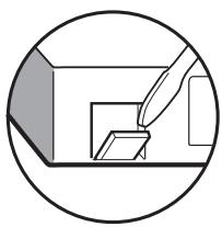
After having recorded a tape, if you wish to keep the recording, use a flat-tripped screwdriver to break off the erasure-prevention tab on the cassette.
To record again on a tape without an erasure-prevention tab, cover the hole with adhesive tape.
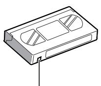
Erasure-prevention tab
Precautions concerning the video cassette tapes
- Do not use tapes that are damaged, tapes that have been cut and repaired or tapes that have been altered in any way.
- Some rewinds may tangle the tape, and therefore their use is not recommended.
- When tapes are recorded over and over again, the recording quality will deteriorate. Refer to "Concerning the Number of Times Tapes can be Rerecorded on" on page 20, and replace the tape with a new tape as required.
Loading
1 Place the cassette, label side up, in the loading slot. Gently push the centre of the cassette until it is loaded automatically.
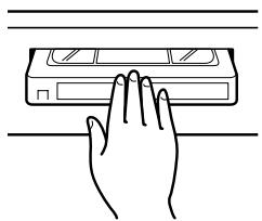
The time display will switch to the reset counter "0H 00M 00S" display.
- The cassette indicator “●” lights on the digital display.
NOTE:
- If you try to record on a cassette without an erasure-prevention tab, the VCR will eject the cassette.
Unloading
1 In stop mode, press the EJECT button.
The cassette is automatically ejected.
NOTES:
- Do not insert any other object in the cassette loading slot, as that may cause injury and damage to the VCR.
- If your hand gets stuck in the cassette loading slot, unplug the power cord and consult the dealer where the unit was bought. Do not forcibly pull your hand out as that may cause severe injuries.
VIDEO CASSETTE TAPES
Correct tape thread check function
This function checks to make sure that the cassette has been correctly loaded so that recording can be carried out.
NOTES:
- After the cassette tape is loaded, the mechanism will operate for about 5 seconds to check that the tape has been threaded (loaded) correctly automatically and the cassette indicator "●" will flash during that period. If the tape is not loaded properly, the cassette will be ejected.
- If the REC, PLAY or STOP button is pressed or if the SHUTTLE ring is turned during the tape thread check operation, the command will only be executed after the tape thread has been checked. Only the EJECT button will operate while the tape thread is being checked.
- If "TAPE IN MODE" in the (GENERAL SET) menu is set to "REC", the recording indicator "○" will light while the tape thread is being checked. However, recording will only start after the tape thread check is completed.
Press the STANDBY/ON button.
Press the MENU button to display the MAIN MENU.
③ Turn the JOG dial to select the "3.GENERAL SET" line, then turn the SHUTTLE ring clockwise.
° The (GENERAL SET) menu appears.
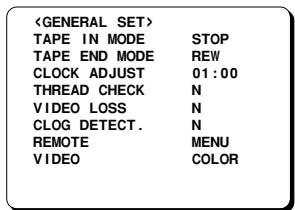
4 Turn the JOG dial until the "THREAD CHECK" setting is highlighted, then turn the SHUTTLE ring clockwise.
⑤ Turn the JOG dial to select the desired mode, then turn the SHUTTLE ring clockwise.
N . The correct tape thread check function is off
Y. The correct tape thread check function is on
Press the MENU EXIT button.
Setting the Action to Take When a Cassette is Loaded
You can set the mode the VCR will go into when a cassette is loaded.
Press the STANDBY/ON button.
Press the MENU button to display the MAIN MENU.
3 Turn the JOG dial to select the "3.GENERAL SET" line, then turn the SHUTTLE ring clockwise.
° The (GENERAL SET) menu appears.
④ Turn the JOG dial until the "TAPE IN MODE" setting is highlighted, then turn the SHUTTLE ring clockwise.
⑤ Turn the JOG dial to select the desired mode, then turn the SHUTTLE ring clockwise.
STOP. . . . . . When tape inserted the VCR, stays in stop mode
REC. When tape inserted the VCR, goes into recording mode
Press the MENU EXIT button.
TAPE MANAGEMENT
This VCR is equipped with a tape management function. Using this function you can protect previous recordings and prevent overuse of the tape by controlling the tape protection term (number of days), the maximum number of re-recordings of the tape and the recording group. For details on how to set this function, refer to "Setting the Tape Management Function".
PROTECT DAY: To set the number of days before the tape can be rerecorded over.
REC PASS SET: To limit the number of rerecordings, in order to maintain a good image quality.
GROUP NO. SET: To manage tapes belonging to different recording groups.
NOTES:
- Before using this function, make sure that the clock is set properly.
- To use the tape management function, it must be set before recording is started.
- The tape management data is recorded at the beginning of the tape.
Operation
When the REC button is pressed, the VCR will rewind the tape to the beginning, and will play back some of the tape to check for the presence of tape management data (no image appears). The message "T. MANAGE. CHK" appears on-screen while the presence and type of data are being checked.
NOTE:
- When performing programme timer recording, single image recording and alarm recording, the tape management function will not operate even if it is active.
If no tape management data is present on the tape
Recording will start according to the settings in the (TAPE MANAGEMENT) menu.
When recording starts, the updated tape management data is recorded onto the tape. If the tape has already been recorded on, the message "USED TAPE" will flash on-screen until recording starts.
If tape management data is present on the tape
The tape management data is checked and if there is no conflict, the VCR will rewind the tape to the beginning, then recording starts and the updated tape management data is recorded onto the tape. The message "T. MANAGE. OK" appears on-screen while the tape is being rewound and the tape management data is being recorded.
If a conflict is found when the tape management data is checked, the (TAPE MANAGEMENT) menu is displayed and the conflicting setting will flash. This menu will show the settings taken from the data recorded on the tape and not the current data settings held in the VCR's (TAPE MANAGEMENT) menu setting. Refer to "Tape Management Conflict Display" for detailed information.
NOTE:
- If the VCR is set for alarm recordings, alarms will be recorded based on the different settings.
If an alarm signal is input while "T. MANAGE. CHK" is displayed, the alarms will be recorded after feeding a certain amount of tape but the data will not be recorded (updated).
If an alarm signal is input during data recording, the alarms will be recorded after data recording.
IMPORTANT NOTES:
- If the tape management data cannot be read, the VCR will switch to stop mode and "DATA NG" will be displayed on-screen.
This may indicate that the beginning of the tape (data recording/reading section) is damaged and the tape may be unusable.
The message “DATA NG” will disappear when the EJECT or PLAY button is pressed.
- Set the security lock function to on in order to protect the security of this feature.
TAPE MANAGEMENT
Setting the Tape Management Function
Press the STANDBY/ON button.
Press the MENU button to display the MAIN MENU.
③ Turn the JOG dial to select the "6.TAPE MANAGEMENT" line, then turn the SHUTTLE ring clockwise.
- The (TAPE MANAGEMENT) menu appears.
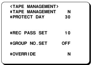
4 Turn the SHUTTLE ring clockwise.
⑤ Turn the JOG dial to select the desired mode, then turn the SHUTTLE ring clockwise.
N. . . . . . The tape management function is not active.
Y.... The tape management function is active.
When setting to “Y”, please continue with the settings below.
⑥ Turn the JOG dial until the “PROTECT DAY” setting is highlighted, then turn the SHUTTLE ring clockwise.
7 Turn the JOG dial to select the desired number of days to protect the tape, then turn the SHUTTLE ring clockwise.
OFF . . . . The tape is not protected.
1-255 . . . Number of days to protect the tape (prevent over-recording), from the date of the last recording on the tape (or the last expected recording date (calculated using the tape length (E-180) and the recording speed)).
NOTE:
- Since the last expected recording date is a calculated date (using the tape length (E-180) and the recording speed), it may be different from the actual last recording date, due to other settings such as alarm recordings, programme timer recordings and holiday settings.
⑧ Turn the JOG dial until the "REC PASS SET" setting is highlighted, then turn the SHUTTLE ring clockwise.
⑨ Turn the JOG dial to select the desired number of re-recording times, then turn the SHUTTLE ring clockwise.
OFF . . . . The number of re-recording times will not be checked.
1-100 . . . Maximum number of re-recording times. (Refer to “Concerning the Number of Times Tapes can be Rerecorded on” on page 20.)
NOTES:
- Since data is read before it is recorded, the number of times will be incremented even if the recording is stopped before the end.
- During autorepeat recording, the re-recording times count will be updated every time the tape is rewound to the beginning. Autorepeat recording will proceed even if the count exceeds the "REC PASS SET" setting.
10 Turn the JOG dial until the "GROUP NO. SET" setting is highlighted, then turn the SHUTTLE ring clockwise.
1 Turn the JOG dial to select the desired group number, then turn the SHUTTLE ring clockwise. OFF . . . The group number will not be checked. 1-15 . . . Group number setting.
12 Turn the JOG dial until the "OVERRIDE" setting is highlighted, then turn the SHUTTLE ring clockwise.
Turn the JOG dial to select the desired override mode, then turn the SHUTTLE ring clockwise. (Refer to "Tape Management Conflict Display" on the next page.)
N. . . . Only EJECT button operation is accepted after a conflict has occurred.
Y. The next operation is accepted after a conflict has occurred. This will override setting.
14 Press the MENU EXIT button.
NOTES:
- Once the tape management data is recorded on tape, it cannot be changed.
- The criteria (condition) for allowing recording will be based on the data recorded on the tape and not the settings in the (TAPE MANAGEMENT) menu.
TAPE MANAGEMENT
Tape Management Conflict Display
If a conflict that prevents recording is found when the tape management function checks the tape data, the (TAPE MANAGEMENT) menu appears with the conflicting setting flashing and the VCR go into the stop mode.
NOTES:
- If "OVERRIDE" is set to "N" (No), the conflicting setting is displayed flashing and the message (PRESS EJECT) appears at the bottom of the screen. Recording under these conditions is not possible. Press the EJECT button to eject the tape. To record on the same tape, set the "OVERRIDE" setting to "Y" and modify the conflicting setting, then insert the same tape and press the REC button. However, if only "PROTECT DAY" and "REC PAS SET" are modified, the menu will be displayed again. Press the REC button one more time to start recording. Recording starts and the tape data is updated.
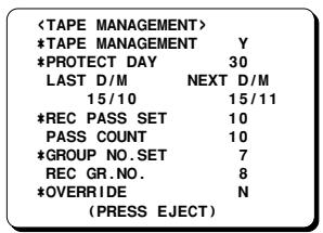
Conflict display sample
- If the "OVERRIDE" is set to "Y" (Yes), the (TAPE MANAGEMENT) menu is displayed and conflicting setting preventing recording will flash and the VCR will switch to stop mode. To enter recording mode, press the REC button.
PROTECT DAY CONFLICT
The tape is protected, and the tape protection term (ex. 30 days) is not yet over.
Under "LAST D/M", the date of the last recording on the tape (or the last expected recording date (calculated using the tape length (E-180) and the recording speed)) is displayed.
Under "NEXT D/M", the date when it will be possible to record on the tape again is displayed.
REC PASS SET CONFLICT
The set number of recording passes has been reached.
The “PASS COUNT” shows the number of recording passes on the tape (ex. since the maximum recording passes number is set to “10”, this prevents further recording.)
NOTES:
- When conducting Autorepeat recording, if the "PASS COUNT" exceeds 100, "101*" will be displayed flashing.
- If using a tape recorded previously on a different type of VCR (no tape data), when the set number of recordings is exceeded, "USED" will flash next to the "PASS COUNT" number.
GROUP NO. SET CONFLICT
The group numbers do not match.
The “REC GR. NO.” shows the tape recording group number (ex. this tape belongs to a different recording group number 8 than the one set 7.)
NORMAL RECORDING
Normal Recording
-Before starting
- Turn the power on to all devices used.
- Load a cassette tape with its erasure-prevention tab intact.
NOTES:
- If "TAPE IN MODE" is set to "REC" in the (GENERAL SET) menu, recording will start.
- Press the ON SCREEN button to display the superimpose display.
Press the REC/PLAY SPEED (or ) button to set the recording speed mode.
- The recording speed mode appears on-screen and on the digital display.
Press the REC button.
The record indicator "O" lights.
Recording starts.
- If the tape end is reached while recording, "OFF" is displayed on the digital display and the unit goes into the mode set at the "TAPE END MODE" setting in the (GENERAL SET) menu. To cancel the "OFF" display, press the STOP, EJECT or PLAY button or turn the SHUTTLE ring.
- When the end of the tape is reached, the TAPE END OUT terminal output will be 0V. To cancel the output, press the STOP button.
③ To stop recording, press the STOP button.
NOTES:
- A tape recording made on this VCR may not play back with the same degree of clarity on a time lapse video cassette recorder from another manufacturer.
- If you press the REC button and the loaded cassette has no erasure-prevention tab, the VCR will eject the cassette.
[Recording Speed Mode]
- The available recording speed modes vary depending on the VCR model.
(TLS-1960P only)
| Recording speed mode (hour mode) | Maximum recording duration (hours) | Recording interval (second) | Audio recording | Tape motion |
| 3 | 3 | 1/50 | Possible | Continuous |
| 12 | 15 | 5/50 |
| 24 | 27 | 9/50 |
| 48 | 51 | 17/50 | Not possible | Intermittent |
| 72 | 75 | 25/50 |
| 96 | 99 | 33/50 |
| 120 | 123 | 41/50 |
| 168 | 171 | 57/50 |
| 240 | 243 | 81/50 |
| 360 | 363 | 121/50 |
| 480 | 483 | 161/50 |
| 720 | 723 | 241/50 |
| 960 | 963 | 321/50 |
| 000 | Single image recording |
(TLS-9924P only)
| Recording speed mode (hour mode) | Maximum recording duration (hours) | Recording interval (second) | Audio recording | Tape motion |
| 3 | 3 | 1/50 | Possible | Continuous |
| 12 | 15 | 5/50 |
| 24 | 27 | 9/50 |
| 000 | Single image recording | Not possible | Intermittent |
NORMAL RECORDING
Record Pause
Recording can be interrupted temporarily.
Press the STILL/PAUSE button during recording. The pause/still indicator “ ” flashes.
NOTES:
- The image appears on-screen but it is not recorded.
- If a recording pause continues for 5 minutes or more, the VCR will switch to stop mode to avoid damaging the tape.
To resume recording, press the REC button, or press the STILL/PAUSE button again.
Recording Check
The image being recorded can be checked.
1 During recording, press the REC CHECK button.
- The tape will be rewound and then played back.
The VCR will then return to the previous recording mode.
NOTE:
- During recording check operations, recording is suspended momentarily.
Concerning the Number of Times Tapes can be Rerecorded on
Depending on the recording speed mode, the tape must be replaced after a certain number of recording times.
Refer to the table below for the maximum number of times a tape can be recorded on.
| Recording speed mode (hour mode) | Maximum number of recording times (with a standard grade tape) |
| 3 | 100 |
| 12 | 50 |
| 24 | 50 |
| 48 | 25 |
| 72 | 15 |
| 96 | 10 |
| 120 | 10 |
| 168 | 5 |
| 240 | 5 |
| 360 | 3 |
| 480 | 2 |
| 720 | 1 |
| 960 | 1 |
| 000 | 1 |
NOTES:
- The maximum number of recording times will vary depending on the location and kind of tape used. Verify the recording quality and replace the tape when the quality starts to deteriorate. The maximum number of recording times indicated above are based on test tapes (E-180) used by the company.
- It is recommended that tape be changed at least as often as in the above table to provide good picture quality in the mode above.
NORMAL RECORDING
Clog Detection
This VCR is equipped with a clog detection function.
The recording quality is monitored automatically. When the heads are dirty and the recording quality deteriorates, the output at the WARNING OUT terminal becomes 0 V (Low) (Refer to "WARNING OUT Terminal" on page 47), the "○" indicator flashes on the digital display.
Setting the clog detection
Press the STANDBY/ON button.
Press the MENU button to display the MAIN MENU.
3 Turn the JOG dial to select the "3.GENERAL SET" line, then turn the SHUTTLE ring clockwise. The (GENERAL SET) menu appears.
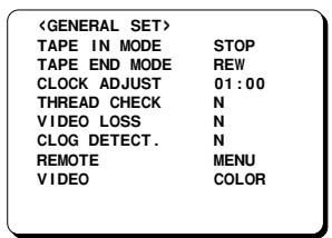
4 Turn the JOG dial until the "CLOG. DETECT." setting is highlighted, then turn the SHUTTLE ring clockwise.
⑤ Turn the JOG dial to select the desired mode, then turn the SHUTTLE ring clockwise. N. . . . . . Recording quality is not monitored Y. . . . . . Recording quality is monitored
Press the MENU EXIT button.
NOTES:
- To cancel the “○” indicator display and reset the WARNING OUT terminal output, press the STOP button.
- Clog detection is not possible if recording in 3-hour mode.
Action to Take when the Video Signal Deteriorates
If there is no video signal during recording or when a menu is not displayed (in stop, fast forward or rewind modes, etc.), "VIDEO LOSS" can be displayed on-screen. If in the (WARNING OUT/CONTROL SET) menu, "VIDEO LOSS" is set to "Y", the output at the WARNING OUT terminal becomes 0V (Low) (Refer to "WARNING OUT Terminal" on page 47).
1 Press the STANDBY/ON button.
Press the MENU button to display the MAIN MENU.
Turn the JOG dial to select the "3.GENERAL SET" line, then turn the SHUTTLE ring clockwise. The (GENERAL SET) menu appears.
Turn the JOG dial until the "VIDEO LOSS" setting is highlighted, then turn the SHUTTLE ring clockwise.
⑤ Turn the JOG dial to select the desired mode, then turn the SHUTTLE ring clockwise.
N . The video loss warning is not active.
Y. The video loss warning is active.
Press the MENU EXIT button.
NORMAL RECORDING
Setting the Mode at the End of the Tape
You can select the mode on the VCR when the tape reaches the end during recording.
1 Press the STANDBY/ON button.
2 Press the MENU button to display the MAIN MENU.
③ Turn the JOG dial to select the "3.GENERAL SET" line, then turn the SHUTTLE ring clockwise.
° The (GENERAL SET) menu appears.
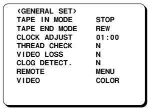
4 Turn the JOG dial until the "TAPE END MODE" setting is highlighted, then turn the SHUTTLE ring clockwise.
⑤ Turn the JOG dial to select the desired mode, then turn the SHUTTLE ring clockwise.
- Setting when not using Autorepeat recording
REW. Rewinds the tape to the beginning, then goes to stop mode
STOP. Goes to stop mode
EJECT . . . . . The cassette is ejected
- Setting when using Autorepeat recording
REPEAT1... Autorepeat recording mode is automatically canceled if there was an alarm trigger
REPEAT2. . . Autorepeat recording mode is active even if there was an alarm trigger
Press the MENU EXIT button.
The video input signal during recording can be set to either colour or black & white.
Press the STANDBY/ON button.
Press the MENU button to display the MAIN MENU.
③ Turn the JOG dial to select the "3.GENERAL SET" line, then turn the SHUTTLE ring clockwise.
4 Turn the JOG dial until the "VIDEO" setting is highlighted, then turn the SHUTTLE ring clockwise.
⑤ Turn the JOG dial to select the desired mode, then turn the SHUTTLE ring clockwise.
COLOR . . . . For recording in colour
B/W . . . . . . For recording in black & white
Press the MENU EXIT button.
NOTES:
- Set to "COLOR" for systems which include colour signals (including cases where black & white signals are mixed in), and set to "B/W" for systems which only use black & white signals.
- Use the same setting for recording and playback.
- If tapes that have been recorded in black & white are played back when the setting is at "COLOR", the recordings will not be played back in colour.
- If using a black & white camera, set to "B/W". Recordings will not be made in colour even if "COLOR" is set.
AUTOREPEAT RECORDING
The same tape can be recorded over many times.
- Follow the Before starting steps, under "NORMAL RECORDING".
1 Press the MENU button to display the MAIN MENU.
2 Turn the JOG dial to select the "3.GENERAL SET" line, then turn the SHUTTLE ring clockwise.
° The (GENERAL SET) menu appears.
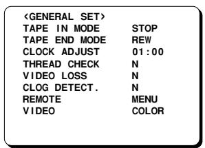
③ Turn the JOG dial until the "TAPE END MODE" setting is highlighted, then turn the SHUTTLE ring clockwise.
Turn the JOG dial to set to "REPEAT1" or "REPEAT2" (Refer to "Setting the Mode at the End of the Tape." on page 22), then turn the SHUTTLE ring clockwise.
Press the MENU EXIT button.
- The REPEAT indicator lights.
Press the REC/PLAY SPEED (or▲) button to set the recording speed mode.
7 Press the REC button.
- Recording starts. When the tape end is reached, the VCR will rewind it to the beginning, and recording will resume.
- When the end of the tape is reached, "OFF" will be displayed and TAPE END OUT terminal output will 0 V, until the rewinding operation starts.
NOTES:
- If there is an alarm trigger during autorepeat recording, "A" is displayed on the digital display and alarm recording will take place. (Refer to "ALARM RECORDING" on page 24.)
- If the "TAPE END MODE" setting is "REPEAT1", the REPEAT indicator will go off if there is an alarm trigger. After alarm recording, the recording will continue to the end of the tape then it will be rewound to the beginning and stop. "OFF" will be displayed on the digital display.
To turn off the "OFF" display, press the STOP, EJECT or PLAY button or turn the SHUTTLE ring.
- If "AL" appears on the digital display and the "TAPE END MODE" setting is "REPEAT1", autorepeat recording is not possible.
ALARM RECORDING
By connecting the ALARM IN terminal to a normally open door switch, an interphone, etc., a recording can be done only when necessary.
Alarm Recording Setting
Alarm recording is performed when there is an input (trigger) at the ALARM IN terminal.
- Make all necessary connections.
- The alarm triggers are received while in recording, stop and stand-by modes.
- Follow the Before starting steps, under "NORMAL RECORDING".
1 Press the MENU button to display the MAIN MENU.
Turn the JOG dial to select the "5.ALM/SERIES REC SET" line, then turn the SHUTTLE ring clockwise.
- The (ALARM/SERIES REC SET) menu appears.
| <ALARM/SERIES REC SET> |
| *ALARM SET | |
| MODE | Y1 |
| SPEED | 3H |
| DURATION | 20S |
| *1 SHOT SET | |
| FIELD | 1 |
| INTERVAL | 1M |
| *SERIES REC | N |
| *TAPE END OUT | 3:00 |
③ Turn the JOG dial until the “MODE” setting is highlighted, then turn the SHUTTLE ring clockwise.
Turn the JOG dial to set the desired alarm recording mode, then turn the SHUTTLE ring clockwise.
Y1....... Alarm recording is done when there is an alarm trigger.
Y2. . . . Alarm recording is done only when there is an alarm trigger during duration of programmed timer recording.
Y3. . . . Alarm recording is done only if there is an alarm trigger and the VCR is not in programmed timer recording mode.
Y4. . . . Alarm recording is done only when there is an alarm trigger during programmed timer recording duration. VCR comes on records only for alarm duration. Timer recording is not possible.
N. Alarm recording is not performed even if there is an alarm trigger.
⑤ Turn the SHUTTLE ring clockwise.
⑥ Turn the JOG dial to set the desired alarm recording speed, then turn the SHUTTLE ring clockwise.
3H. 3-hour mode recording
12H. 12-hour mode recording
24H. 24-hour mode recording
NC . Recording at the speed already set
7 Turn the SHUTTLE ring clockwise.
⑧ Turn the JOG dial to set the desired alarm recording duration (20S, 40S, 1M, 2M, 3M, 4M, 5M, or CC), then turn the SHUTTLE ring clockwise.
20S-5M. . Recording only for the displayed duration
CC . . . . . Recording as long as the alarm signal is being input (minimum 5 seconds)
9 Press the MENU EXIT button.
NOTES:
- During alarm recording all buttons are disabled.
- If “OFF” appears on the digital display, alarm recording is not possible in order to prevent the recorded tape to be recorded over. To cancel the “OFF” display, press the STOP, EJECT or PLAY button or turn the SHUTTLE ring.
- If an alarm trigger is received while alarm recording is in progress, recording duration for the second alarm will be calculated from that point. The alarm counter will register the alarm, but it will not be found during an alarm scan and alarm search.
- If there is a power failure during alarm recording, and the power is restored within the recording set duration, alarm recording will continue.
- If the alarm recording duration is short, the alarms may not be found during an alarm scan or an alarm search. If the alarms are going to be reviewed using alarm scan or alarm search, then in 3-hour mode, 20-second or more recording duration should be used.
- To do alarm recording during series recording, set "MODE" to "Y1" or "Y3". Alarm recording will be conducted only if the VCR is recording.
- If the recording speed mode is "000", the recording will be in 3-hour mode irrespective of the alarm recording speed mode setting.
ALARM RECORDING
Alarm Recording Reset Function
To stop the recording of an alarm, close the connection between the ALARM RESET IN terminal and the COM terminal during alarm recording.
Alarm Recording Counter Display
- During alarm recording, "A" will be flashing on the digital display.
- If a superimpose display is being displayed and "ALARM COUNT" has been set to "Y" in the (DISPLAY/SW OUT SET) menu, the number of alarm recordings will flash on the monitor screen.
- The maximum display number of alarm recordings is "999". At the next alarm recording the counter will indicate "000".
- When the (ALARM LOG) menu appears, press the MENU RESET button to reset the alarm counter to "000" (all the data of the (ALARM LOG) menu is reset).
Connections to the ALARM IN Terminal
Connect a make-contact (no voltage) switch between the ALARM IN and COM terminals.
Checking the Alarm Recordings Time
Press the STANDBY/ON button.
Press the MENU button to display the MAIN MENU.
③ Turn the JOG dial to select the "9.OTHERS" line, then turn the SHUTTLE ring clockwise.
° The (OTHERS) menu appears.
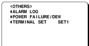
4 Turn the JOG dial to select the "ALARM LOG" line, then turn the SHUTTLE ring clockwise.
- The (ALARM LOG) menu appears.
The number of alarm recordings, and the 10 most recent alarm recording times are displayed.
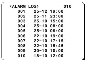
- Continue turning the JOG dial to display the next (or previous) 10 alarm recording entries. When the number of alarm recording entries reaches 100, the older ones are erased as new ones are memorized.
Press the MENU EXIT button.
NOTE:
- If the MENU RESET button is pressed while the (ALARM LOG) menu is displayed, the displayed data is erased. "AL" will be erased from the digital display.
ALARM RECORDING
Alarm Search
To go to the beginning of a desired alarm recording.
1 Press the STANDBY/ON button.
Press the SEARCH button during stop mode.
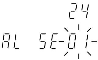
° "AL SEARCH 01" appears on screen.
Press the REC/PLAY SPEED (or ) button to set the desired alarm number (01 to 99), then turn the SHUTTLE ring clockwise (or counterclockwise).
- The desired alarm is searched for and a still image of the beginning of the alarm recording appears on-screen.
NOTE:
- The alarm number is relative to the actual tape position. (Please refer to the illustration below.)
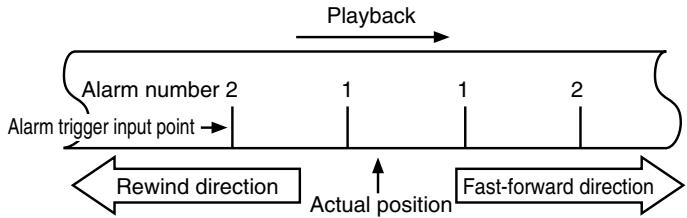
4 Press the PLAY button.
口 Playback starts.
NOTES:
- If the end of the tape is reached during a search, the tape will rewind and stop. If the beginning of the tape is reached, it will stop.
- This function does not operate when a warning display appears on the digital display.
Alarm Scan
To look for an alarm recording by viewing the first 5 seconds of each alarm recording.
Press the STANDBY/ON button.
Press the SEARCH button twice during stop mode.
° "AL SCAN" will be displayed on screen.
③ Turn the SHUTTLE ring clockwise (or counterclockwise).
The unit will advance (or rewind) the tape at high speed and playback the first 5 seconds of every alarm recording.
To cancel the alarm scan mode, press the STOP button.
While the desired recording is being played back, press the PLAY button.
- Playback starts and alarm scan mode is canceled.
NOTES:
- If the end of the tape is reached during a scan, the tape will rewind and stop. If the beginning of the tape is reached, it will stop.
- This function does not operate when a warning display appears on the digital display.
PROGRAMME TIMER RECORDING
There are three programme timer recording methods, daily recording, weekly recording or recording on certain days of the week.
Example 1: To record on every Saturday from 9:00 AM to 5:00 PM (17:00), in 24-hour mode (recording speed).
- Follow the Before starting steps, under "NORMAL RECORDING".
1 Press the MENU button to display the MAIN MENU.
Turn the JOG dial to select the "7.TIMER SET" line, then turn the SHUTTLE ring clockwise.
- The (TIMER SET) menu appears.
| < TIMER SET> |
| WEEK | START | STOP | SPD |
| SUN | ---- | ---- | ---- N |
| MON | ---- | ---- | ---- N |
| TUE | ---- | ---- | ---- N |
| WED | ---- | ---- | ---- N |
| THU | ---- | ---- | ---- N |
| FRI | ---- | ---- | ---- N |
| SAT | ---- | ---- | ---- N |
| DAILY | ---- | ---- | ---- N |
| EXT | ********** | ********** | ---- N |
③ Turn the JOG dial until the "SAT" (Saturday) line is highlighted, then turn the SHUTTLE ring clockwise.
4 Turn the JOG dial to change the weekday, then turn the SHUTTLE ring clockwise.
If no change, turn the SHUTTLE ring clockwise.
The recording start hour position starts flashing.
NOTE:
- All of the lines other than the bottom line can be set to "SUN", "MON", "TUE", "WED", "THU", "FRI", "SAT", "DAILY", "MO-SA" (Monday to Saturday) or "MO-FR" (Monday to Friday).
⑤ Turn the JOG dial to set the recording start hour (ex: 09), then turn the SHUTTLE ring clockwise.
The recording start minutes position starts flashing.
⑥ Turn the JOG dial to set the recording start minutes (ex: 00), then turn the SHUTTLE ring clockwise.
The recording stop hour position starts flashing.
7 Turn the JOG dial to set the recording stop hour (ex: 17), then turn the SHUTTLE ring clockwise.
- The recording stop minutes position starts flashing.
Turn the JOG dial to set the recording stop minutes (ex: 00), then turn the SHUTTLE ring clockwise.
- The "SPD" (recording speed) position will start flashing.
NOTE:
- If the set stop time is earlier than or the same time as the set start time, the VCR will consider the stop time to be the following day, and "T" will be displayed next to the recording stop time.
⑨ Turn the JOG dial to select the recording speed mode (ex: 24), then turn the SHUTTLE ring clockwise.
° "N" will start flashing.
10 Turn the JOG dial to select the desired programme timer recording mode (Y), then turn the SHUTTLE ring clockwise.
Y. Recording will take place
N .Recording will not take place
| <TIMER SET> |
| WEEK | START | STOP | SPD |
| SUN | ---- | ---- | ---- |
| MON | ---- | ---- | ---- |
| TUE | ---- | ---- | ---- |
| WED | ---- | ---- | ---- |
| THU | ---- | ---- | ---- |
| FRI | ---- | ---- | ---- |
| SAT | 09:00 | 17:00 | 24 Y |
| DAILY | ---- | ---- | ---- |
| EXT | ********** | ********** | ---- |
- Repeat steps ③ to ⑩ to programme timer recordings for other days of the week.
- If a wrong setting has been entered, turn the SHUTTLE ring counterclockwise to move to the setting to be changed, then turn the JOG dial to enter the correct setting.
1 Press the MENU EXIT button.
12 Press the TIMER button.
The timer recording indicator "□" will light on the digital display. The VCR is now in timer recording stand-by mode.
NOTE:
- To modify, cancel or stop timer recording, press the TIMER button to cancel the timer recording mode.
PROGRAMME TIMER RECORDING
A timer recording of more than 24 hours can only be set on the 7th (SAT) and 8th (DAILY) lines of the (TIMER SET) menu.
Example 2: To record every week from Friday at 9:00 PM (21:00) to Monday at 7:00 AM, in 96-hour mode (recording speed).
-
Follow the Before starting steps, under "NORMAL RECORDING".
1 Follow steps 1 and 2 under "PROGRAMME TIMER RECORDING" on page 27.
-
The (TIMER SET) menu appears.
| < TIMER SET> |
| WEEK | START | STOP | SPD |
| SUN | ---- | ---- | ---- |
| MON | ---- | ---- | ---- |
| TUE | ---- | ---- | ---- |
| WED | ---- | ---- | ---- |
| THU | ---- | ---- | ---- |
| FRI | ---- | ---- | ---- |
| SAT | ---- | ---- | ---- |
| DAI LY | ---- | ---- | ---- |
| EXT | ********** | ********** | ---- |
Turn the JOG dial until the "SAT" (Saturday) line is highlighted, then turn the SHUTTLE ring clockwise.
③ Turn the JOG dial, to set the desired start day of the week (ex: FRI), then turn the SHUTTLE ring clockwise.
4 Turn the JOG dial to set the recording start hour (ex: 21), then turn the SHUTTLE ring clockwise.
⑤ Turn the JOG dial to set the recording start minutes (ex: 00), then turn the SHUTTLE ring clockwise.
⑥ Turn the JOG dial to set “**” for the recording stop hour, then turn the SHUTTLE ring clockwise.
The rest of the line settings will change to **: ** *** *, the day of the next line will change to the next day and the start time will change to **: ** automatically.
7 Turn the JOG dial to set the desired stop day of the week (ex: MON), then turn the SHUTTLE ring clockwise.
Turn the JOG dial to set the recording stop hour (ex: 07), then turn the SHUTTLE ring clockwise.
⑨ Turn the JOG dial to set the recording stop minutes (ex: 00), then turn the SHUTTLE ring clockwise.
10 Turn the JOG dial to select the recording speed mode (ex: 96), then turn the SHUTTLE ring clockwise.
1 Turn the JOG dial to select "Y".
| <TIMER SET> |
| WEEK | START | STOP | SPD |
| SUN | ---- | ---- | ---- |
| MON | ---- | ---- | ---- |
| TUE | ---- | ---- | ---- |
| WED | ---- | ---- | ---- |
| THU | ---- | ---- | ---- |
| FRI | ---- | ---- | ---- |
| FRI | 21:00 | *** | *** |
| MON | *** | 07:00 | 96 Y |
| EXT | ***** | ***** | ---- N |
12 Press the MENU EXIT button.
13 Press the TIMER button.
PROGRAMME TIMER RECORDING
Setting the Holidays
By setting the holidays, timer recording will be conducted on those days, as set for Sundays.
1 Press the STANDBY/ON button.
2 Press the MENU button to display the MAIN MENU.
③ Turn the JOG dial to select the "8.HOLIDAY SET" line, then turn the SHUTTLE ring clockwise.
O The (HOLIDAY SET) menu appears.
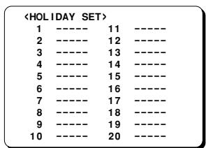
4 Turn the JOG dial to select the desired line, then turn the SHUTTLE ring clockwise.
⑤ Turn the JOG dial to set day of the holiday, then turn the SHUTTLE ring clockwise.
⑥ Turn the JOG dial to set month of the holiday, then turn the SHUTTLE ring clockwise.
Repeat steps 4 to 6 to set up to 20 holidays.
7 Press the MENU EXIT button.
NOTES:
- If setting holidays, be sure that a timer recording is set for Sunday. If not, this function will not operate.
- If a timer recording for Sundays is entered, the holidays timer recording will not function if the programme timer recording mode is set to "N".
- If timer recording has been set for 24 hours or more, after midnight the recording will be carried out according to the (TIMER SET) menu settings, even if holiday timer recording has been set.
- To erase a setting, follow the same procedure as above, but at step ⑤ and ⑥, enter “--” instead of a setting.
Changing a Programme Timer Recording
1 Follow steps 1 and 2 under "PROGRAMME TIMER RECORDING" on page 27.
Turn the JOG dial until the setting (line) to be changed is highlighted, then turn the SHUTTLE ring clockwise.
③ Turn the SHUTTLE ring clockwise, until the setting to correct is flashing.
4 Turn the JOG dial, to correct the setting.
Press the MENU EXIT button, then press the TIMER button.
To Cancel a Programme Timer Recording
1 Follow steps 1 and 2 under "PROGRAMME TIMER RECORDING" on page 27.
Turn the JOG dial until the setting (line) to be canceled is highlighted, then turn the SHUTTLE ring clockwise.
③ Turn the SHUTTLE ring clockwise, until "Y" is flashing.
4 Turn the JOG dial, to select "N".
Press the MENU EXIT button, then press the TIMER button.
To cancel all programme timer recordings
1 Follow steps 1 and 2 under "PROGRAMME TIMER RECORDING" on page 27.
Press the MENU RESET button.
° All programmed timer recordings are erased.
3 Press the MENU EXIT button.
PROGRAMME TIMER RECORDING
NOTES:
- During timer recording or timer recording stand-by, all the buttons on the VCR, except the TIMER button and the buttons to set/cancel the security lock (see page 38), are disabled.
- If the power fails, the recording will be interrupted. When the power is restored, the recording will resume if the stop time has not yet been reached, and "P" will be displayed on the digital display. The VCR internal battery is completely recharged after the VCR has been connected to a live outlet for 48 hours, and it will maintain all the VCR settings memory for up to 30 days.
- Set the timer recordings so that the recording times do not overlap. If they do, the one with the earliest recording start time will have priority. (See chart below.)
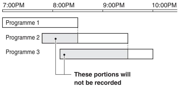
- If no timer recording is set or a cassette without erasure-prevention tab is loaded, when the TIMER button is pressed the timer recording indicator “□” will start flashing.
- If "OFF" is displayed on the digital display, timer recording is not possible in order to prevent the recorded tape to be recorded over.
- If the recording speed mode has been set to "000", single image recordings will be made.
Recording can be controlled by an external start/stop signal input at the EXT TIMER IN terminal.
While there is input at the EXT TIMER IN terminal, the external input indicator "E" will light on the digital display and the input will be recorded. Recording will stop when there are no more input signals.
Example 3: To record using the signal input at the EXT TIMER IN terminal, in 24-hour mode.
- Follow the Before starting steps, under "NORMAL RECORDING".
NOTE:
- External timer input recording can only be set on the "EXT" line of the (TIMER SET) menu.
1 Follow steps 1 and 2 under "PROGRAMME TIMER RECORDING" on page 27.
Turn the JOG dial until the "EXT" line is highlighted, then turn the SHUTTLE ring clockwise.
③ Turn the JOG dial to select the recording speed mode (ex: 24), then turn the SHUTTLE ring clockwise.
4 Turn the JOG dial to select "Y".
| <TIMER SET> |
| WEEK | START | STOP | SPD |
| SUN | ---- | ---- | ---- |
| MON | ---- | ---- | ---- |
| TUE | ---- | ---- | ---- |
| WED | ---- | ---- | ---- |
| THU | ---- | ---- | ---- |
| FRI | ---- | ---- | ---- |
| SAT | ---- | ---- | ---- |
| DAILY | ---- | ---- | ---- |
| EXT | ********** | ********** | 24 Y |
Press the MENU EXIT button.
Press the TIMER button.
NOTES:
- Alarm recording is not possible using this function.
- Alarm recording reset function is not possible using this function.
- Other timer recordings using the standard procedure can also be programmed.
SERIES RECORDING
Using 2 VCRs or more, the series recording function lets you switch recording from one unit to the next (only with VCRs of the same model as this one).
Series Recording Setup
- Connect 2 VCRs or more as illustrated below.
- Follow the Before starting steps, under "NORMAL RECORDING".
Press the REC/PLAY SPEED (or ) button to set the recording speed mode.
2 Set the following items as indicated.
| Item | VCR No.1 | VCR No.2 and on |
| Cassette tape | Loaded | Loaded |
| Operation mode | Stop | Stop |
| “TAPE END MODE”(in (GENERAL SET) menu) | REW, STOP or EJECT | REW, STOP or EJECT |
| “SERIES REC” (in (ALARM/SERIES REC SET) menu) | Y (YES) | Y (YES) |
| Timer recording | OFF (not set) | OFF (not set) |
| Power | ON | Stand-by |
| Security lock | Canceled | Set |
3 Press the REC button on VCR No.1.
Recording will start in series recording mode.
Set the security lock on VCR No.1.
Operation
The output signal at the TAPE END OUT terminal will be present either at the point when the counter reading is 3H 00M 00S or when VCR No. 1 reaches the end of the tape, whichever is first.
When this signal is received by VCR No. 2, it will start recording.
When the tape end is reached, operation is then carried out according to the "TAPE END MODE" setting in the (GENERAL SET) menu.
NOTES:
- When using tapes that are based on the VHS standard, a single tape can be used to record 3H 00M 00S or more based on the counter setting.
- If "SERIES REC" is set to "N" in the (ALARM/SERIES REC SET) menu, series recording will not be possible.
- The counter must start from the beginning of tape, or the series recording out will not function properly.
- Even if "OFF" is displayed, series recording will be conducted if there is an input at the SERIES IN terminal.
Loop recording
- Connect the output from the TAPE END OUT terminal of the last VCR to the SERIES IN terminal of the first VCR.
- The "TAPE END MODE" in (GENERAL SET) menu should be set to "REW" for all units without fail.
- In loop recording mode, the tape will be re-recorded over. If you need to keep the recorded information, please eject the tape after recording is complete and insert a new tape.
Connection
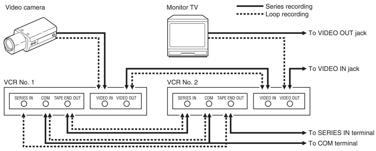
English
SINGLE IMAGE RECORDING
The single image recording function of this VCR can be used to create image data files or animations.
Single Image Recording Setup
- Follow the Before starting steps, under "NORMAL RECORDING".
1 In stop mode, press the REC/PLAY SPEED (or ) button, to set the recording speed to "000".
Press the MENU button to display the MAIN MENU.
③ Turn the JOG dial to select the "5.ALARM/SERIES REC SET" line, then turn the SHUTTLE ring clockwise.
- The (ALARM/SERIES REC SET) menu appears.
| <ALARM/SERIES REC SET> |
| *ALARM SET |
| MODE | Y1 |
| SPEED | 3H |
| DURATION | 20S |
| *1 SHOT SET |
| FIELD | 1 |
| INTERVAL | 1M |
| *SERIES REC | N |
| *TAPE END OUT | 3:00 |
4 Turn the JOG dial until the "FIELD" setting is highlighted, then turn the SHUTTLE ring clockwise.
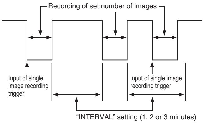
⑤ Turn the JOG dial to set the number of fields (images) to record every time(1, 2, 3, 4, 5, 10, 30, 60), then turn the SHUTTLE ring clockwise.
⑥ Turn the SHUTTLE ring clockwise.
7 Turn the JOG dial to set the interval between each image recording (1M, 2M, 3M), then turn the SHUTTLE ring clockwise.
Press the MENU EXIT button.
9 Press the REC button.
- The single image recording mode will be activated (the VCR will be in recording stand-by mode).
Press the REC button one more time, or send a trigger through the 1 SHOT IN terminal on the back panel, to start the single image recording.
NOTE:
- If a setting other than "1" is selected for "FIELD" at step ⑤, recording will be done in 120-hour mode. The recording speed cannot be modified.
When finished, press the STOP button.
NOTES:
- The trigger at the 1 SHOT IN terminal should be on for 0.1 sec. or more.
- The trigger interval at the 1 SHOT IN terminal varies according to the number of images to record, but should be over 1 sec.
- Alarm recording is not possible during single image recording.
- During the "INTERVAL" period set for single image recording, the WARNING OUT terminal will not be 0V even if the "NON REC" on the (WARNING OUT/CONTROL SET) menu is set to "Y".
- If a single image recording trigger is not received (or if the REC button is not pressed) during the duration set for "INTERVAL", single image recording will be conducted automatically after the set duration.
- If a single image recording trigger is received (or if the REC button is pressed) during the duration set for "INTERVAL", single image recording will be conducted immediately.
- When using the 1 SHOT IN terminal, connect a make-contact switch (no voltage) between the 1 SHOT IN and COM terminals.
NORMAL PLAYBACK
Normal Playback
1 Turn on the power to the VCR and TV monitor.
Load the video cassette tape.
Press the REC/PLAY SPEED (or ) button to select the playback speed mode.
The selected playback speed mode is displayed on the digital display.
NOTES:
- A slow motion effect or accelerated playback effect can be achieved by using a slower or faster playback speed than the speed used for recording.
- If the playback speed mode is set to "000", playback (step 4) will not be possible.
4 Press the PLAY button.
Playback starts.
- If necessary, adjust the tracking to eliminate the noise from the picture.
- If the image is unstable (rolling vertically), adjust the vertical lock control to correct.
5 To stop playback, press the STOP button.
To advance (or rewind) the tape, turn the SHUTTLE ring clockwise (or counterclockwise).
NOTE:
- A tape recorded on a time lapse video cassette recorder produced by another manufacturer may not play back with the same degree of clarity on this unit.
Tracking Control
If there is noise in the image during playback,
1 While looking at the playback picture, press the TRACKING+ button repeatedly to minimize the noise.
2 If it cannot be minimized, press the TRACKING button repeatedly.
NOTE:
- This function does not operate when a warning display appears on the digital display.
Vertical Lock Control
During still image mode,
Press the V. LOCK+ button repeatedly to reduce the vertical rolling of the image.
If it cannot be corrected, press the V. LOCK- button repeatedly.
NOTE:
- This function does not operate when a warning display appears on the digital display.
Sharpness Control
1 During playback, press and hold the SHARPNESS button for 3 seconds or more.
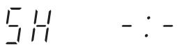
° "SH -: - appears on the digital display.
Press the SOFT (or SHARP) button for the desired sharpness of the image.
③ When finished, press the SHARPNESS button.
NOTE:
- This function does not operate when a warning display appears on the digital display.
AudioPlayback
- Audio playback is only possible in 3-hour, 12-hour and 24-hour modes.
- The playback speed has to be the same as the recording speed, for normal playback of the audio.
- For a tape recorded in 12-hour and 24-hour recording modes, to playback the audio, press the AUDIO ON button after pressing the PLAY button. "A" will be displayed to the left of the playback speed on the digital display.
SPECIAL PLAYBACK
Picture Search (Forward and Reverse)
1 Turn the SHUTTLE ring clockwise (or counterclockwise), during normal playback. See "SHUTTLE Ring Operation".
The image can be seen while the tape is advanced (or rewound) at high speed.
To return to normal playback, release the SHUTTLE ring.
NOTES:
- During picture search, noise (horizontal bars) will appear in the picture.
The sound is muted.
Still Image
1 Press the STILL/PAUSE button, during normal playback.
° A still image can be viewed.
To return to normal playback, press the PLAY button.
NOTES:
- If still mode continues for 5 minutes or more, the VCR will go into stop mode to avoid damaging the tape.
- If the image is unstable (rolling vertically), adjust the vertical lock control to correct.
The sound is muted.
Field Advance (Forward and Reverse)
1 Turn the JOG dial clockwise (or counterclockwise), during still image mode.
- The still image is advanced (or rewound) of one image (field).
Turn the dial faster to increase the speed of the field advance.
To return to normal playback, press the PLAY button.
NOTES:
- During reverse field advance, noise will appear in the picture.
- If field advance mode continues for 5 minutes or more, the VCR will switch to stop mode to avoid damaging the tape.
The sound is muted.
ReversePlayback
1 Turn the SHUTTLE ring counterclockwise and hold it, during normal playback. See "SHUTTLE Ring Operation".
Reverse playback will start.
To return to normal playback, release the SHUTTLE ring.
NOTES:
- During reverse playback, noise will appear in the picture.
- If operated from normal playback mode, reverse playback is only possible during 3-hour playback speed mode.
The sound is muted.
Slow motion (Forward and Reverse)
1 Turn the SHUTTLE ring clockwise (or counterclockwise) and hold it, during still image mode.
See "SHUTTLE Ring Operation".
- Forward (or reverse) slow motion playback will start.
To return to normal playback, press the PLAY button.
NOTES:
- If slow motion mode continues for 5 minutes or more, the VCR will switch to stop mode to avoid damaging the tape.
The sound is muted.
SPECIAL PLAYBACK
SHUTTLE Ring Operation
From normal playback, still image, stop mode, etc., turn the clockwise or counterclockwise to select a mode as indicated below.
1 Turn the SHUTTLE ring in either direction where the desired mode is selected.
Operation will not return to the original mode when the SHUTTLE ring is released.
| Reverse direction | Original mode | Forward direction |
| Shuttle operations that cannot use the SHUTTLE HOLD button. |
| Rewind | | Stop | | Fast forward |
| Rewind | | Fast forward | | Forward picture search (Locked) |
| Reverse picture search (Locked) | | Rewind | | Fast forward |
| Reverse picture search (Locked) | | *1 | | Fast forward |
| Rewind | | *2 | | Forward picture search (Locked) |
Shuttle operations that can use the SHUTTLE HOLD button.
| Reverse picture search | Reverse playback | Normal playback | Normal playback | Forward picture search |
| Reverse picture search | Reverse playback | Reverse Slow motion | Still image | Slow motion | Normal playback | Forward picture search |
1: Forward picture search.
2: Reverse picture search.
NOTES:
- If operated from still image mode and playback mode, operation will return to the original mode when the SHUTTLE ring is released.
- If operated from normal playback mode, reverse playback is only possible during 3-hour playback speed mode.
The sound is muted.
- While turning the SHUTTLE ring, press the SHUTTLE HOLD button. The operation in progress at that time will continue even when the SHUTTLE ring is released. To stop the operation, press the SHUTTLE HOLD button or the STOP button, or turn the SHUTTLE ring.
DAY/TIME SEARCH
Day/Time Search
This searches for a specified day/time for still images to be played back.
1 Press the STANDBY/ON button.
Press the SEARCH button three times during stop mode.
° "T/D SEARCH 01 00:00" will be displayed on screen.
3 Press the REC/PLAY SPEED (or ) button to set the desired day, then press the SHIFT → button.
Press the REC/PLAY SPEED (or ) button to set the desired hour, then press the SHIFT → button.
Press the REC/PLAY SPEED (or ) button to set the desired minutes.
NOTES:
- The setting can be made in 10 minutes increments only.
- For recordings made on other VCRs, the exact time may not be found even if the minutes are entered. For tapes recorded on older models of VCRs produced by this company (the ones without a minutes setting for the day/time search function), make sure to set the minutes to "00".
⑥ Turn the SHUTTLE ring clockwise (or counterclockwise).
The desired day/time is searched and a still image of the recording will appear on-screen.
7 Press the PLAY button.
Playback will start.
NOTES:
- If the end of the tape is reached during a search, the tape will rewind and stop. If the beginning of the tape is reached, it will stop.
- The alarm and day/time data are recorded on the tape in a similar format. If they overlap, the alarm data will have the priority. Therefore, when searching for a day/time when an alarm recording was done, the day/time search will not stop at the desired location. In such a case, use alarm scan to find the desired recording location.
- The day/time search function may not operate correctly if searching for a timer recording time or if the clock on the recording VCR has been adjusted using the CLOCK ADJUSTMENT function.
- If the recording has been made in 120-hour or more mode, the day/time search with a minutes setting (see step ⑤ above) will not operate. When using the day/time search function on such a recording, set the minutes (see step ⑤ above) to "00".
- If a recording on a tape extends for over a one month period, the same day may be present twice on the tape. If such a day is searched, since there is no month search setting, the desired day may not be found.
- This function does not operate when a warning display appears on the digital display.
TAPE COUNTER
Using the counter, it is easy to find a desired recording.
Press the COUNTER RESET button, at the beginning of the desired recording.
The counter will be reset to "OH 00M 00S".
Press the COUNTER MEMORY button.
° "M" appears on the digital display.
To cancel the counter memory function, press the COUNTER MEMORY button a second time.
After recording or playback, turn the SHUTTLE ring counterclockwise from stop mode.
The tape is rewound to the counter "OH 00M 00S" reading.
If you rewind the tape past the "OH 00M 00S" position, turn the SHUTTLE ring clockwise.
NOTES:
- There is no tape counter indication for the blank portions of the tape.
- In the 3-hour recording speed mode only, the tape counter indicates real hours, minutes and seconds.
- In the other recording speed modes, the tape counter indication is a ratio of the 3-hour mode base indication. (In 24-hour recording mode, each "second" of the tape counter actually represents approximately 27/3 = 9 real seconds.)
- There may be a slight discrepancy between the position shown on the tape counter and the actual tape position.
- When rewinding the tape past the "0H 00M 00S" position, a minus (-) sign will be displayed.
SECURITY LOCK
This VCR is equipped with two types of security lock: a quick method security lock and a 4 digit security lock.
The security lock function is designed to prevent accidental stopping of recording if the STOP button is pressed inadvertently.
NOTE:
- The security lock cannot be engaged while a menu is displayed.
Quick Method Security Lock
1 While holding the SHIFT → button, press the REC/PLAY SPEED button.
"!” appears on the digital display.
To cancel the security lock, while holding the SHIFT → button, press the REC/PLAY SPEED button,
"1" will be erased from the digital display.
NOTES:
- While the security lock is engaged all commands, except the one to cancel the security lock, are disabled.
- The quick method security lock will be cancelled by pressing the ALL RESET button.
4 Digit Security Lock
When the security lock is applied, the VCR cannot be operated by someone who does not know the correct password. You need to enter the password in order to operate the VCR.
Setting the 4 digit security lock
Press the SECURITY LOCK button.
O- - - - appears on the digital display.
Use the JOG dial and SHUTTLE ring to set the 4 digit pass word.
JOG dial. To select a digit
SHUTTLE ring . . . . . To move between digits
- When the 4th digit is entered and the SHUTTLE ring is then turned clockwise, the lock is engaged and “ ” appears on the digital display.
NOTE:
- When the digits are entered and the SHUTTLE ring is turned clockwise, the numerals are replaced by “-” characters.
Cancel the 4 digit security lock
Press any button.
° “1” flashes in the digital display for 3 seconds, and then “- - - - ” appears.
Use the JOG dial and SHUTTLE ring to set the 4 digit pass word.
JOG dial. . . . . . . . . . . . . . . . . . . . . . . . . . . . . . . . . . . . . . . . . . . . . . . . . . . . . . . . . . . . . . . . . . . . . . . . . . . . . . JOG dial. 1. JOG dial. 2. JOG dial. 3. JOG dial. 4. JOG dial. 5. JOG dial. 6. JOG dial. 7. JOG dial. 8. JOG dial. 9. JOG dial. 10. JOG dial. 11. JOG dial. 12. JOG dial. 13. JOG dial. 14. JOG dial. 15. JOG dial. 16. JOG dial. 17. JOG dial. 18. JOG dial. 19. JOG dial. 20. JOG dial. 21. JOG dial. 22. JOG dial. 23. JOG dial. 24. JOG dial. 25. JOG dial. 26. JOG dial. 27. JOG dial. 28. JOG dial. 29. JOG dial. 30. JOG dial. 31. JOG dial. 32. JOG dial. 33. JOG dial. 34. JOG dial.
SHUTTLE ring . . . . . To move between digits
- When the 4th digit is entered and the SHUTTLE ring is then turned clockwise, the lock is disengaged and “ 1 ” disappears from the digital display.
- If the password is incorrect, the VCR returns to the initial condition.
NOTE:
- Operation 2 should be carried out within 7 seconds of starting setting 1.
CLOCK ADJUSTMENT
The time for the second and subsequent VCRs can be set to the same time as the first VCR.
A signal from a separate device can also be used to set the time for the second and subsequent VCRs to the same time as the first VCR. When using the signal from a separate device to set the time, input a 0V signal to the CONTROL IN terminal of the first VCR for 100 ms or longer.
1 Press the STANDBY/ON button.
2 Press the MENU button to display the MAIN MENU.
③ Turn the JOG dial to select the "3.GENERAL SET" line, then turn the SHUTTLE ring clockwise.
Turn the JOG dial until the "CLOCK ADJUST" setting is highlighted, then turn the SHUTTLE ring clockwise.
⑤ Turn the JOG dial to set the hour at which the adjustment will be conducted, then turn the SHUTTLE ring clockwise.
NOTE:
- The clock adjustment cannot be set to "00:00".
Example
| <GENERAL SET> |
| TAPE IN MODE | STOP |
| TAPE END MODE | REW |
| CLOCK ADJUST | 03:00 |
| THREAD CHECK | N |
| VIDEO LOSS | N |
| CLOG DETECT. | N |
| REMOTE | MENU |
| VIDEO | COLOR |
Press the MENU EXIT button.
The setting procedure on the first VCR is now completed.
Repeat the procedure for all the other VCRs, setting "CLOCK ADJUST" (to the same time as set on the first VCR).
NOTE:
- This function will not operate on the day the summer/standard time is changed.
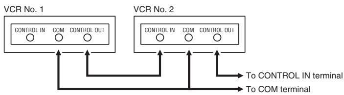
Connection
The input and output terminal signals can be selected so that the VCR can be connected to older models of VCR.
1 Press the STANDBY/ON button.
Press the MENU button to display the MAIN MENU.
③ Turn the JOG dial to select the “9. OTHERS” line, then turn the SHUTTLE ring clockwise.
° The (OTHERS) menu appears.
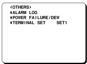
Turn the JOG dial until the "TERMINAL SET" setting is highlighted, then turn the SHUTTLE ring clockwise.
⑤ Turn the JOG dial to select the desired mode, then turn the SHUTTLE ring clockwise.
SET1 According to indication on back panel. (Select when not connecting to an older model.)
SET2 CONTROL IN is set to CLOCK IN, SERIES IN is set to EJECT IN, CONTROL OUT is set to CLOCK OUT and TIMER OUT is set to EJECT OUT. (Select when connecting to an older model.)
⑥ When finished, press the MENU EXIT button.
NOTE:
- If set to "SET2", the "SERIES REC" line will not appear in the (ALARM/SERIES REC SET) menu.
SETTING THE CASSETTE EJECT MODE
Cassette Eject Setup
When using two or more VCRs, the cassette tapes of all the VCRs or some of the VCRs can be ejected at the same time.
NOTE:
- “TERMINAL SET” in the (OTHERS) menu should always be set to “SET2”.
1 Press the STANDBY/ON button.
Press the MENU button to display the MAIN MENU.
③ Turn the JOG dial to select the "4.WARNING OUT/CONTR. SET" line, then turn the SHUTTLE ring clockwise.
- The (WARNING OUT/CONTROL SET) menu appears.
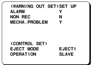
4 Turn the JOG dial until the "EJECT MODE" setting is highlighted, then turn the SHUTTLE ring clockwise.
⑤ Turn the JOG dial to select the desired cassette eject mode, then turn the SHUTTLE ring clockwise.
EJECT1 . . . The cassette is ejected only if the VCR is not in recording or recording pause mode.
EJECT2 . . . The cassette is ejected only if the VCR is in stop mode.
⑥ Turn the JOG dial until the “OPERATION” setting is highlighted, then turn the SHUTTLE ring clockwise.
7 Turn the JOG dial to select the desired operation, then turn the SHUTTLE ring clockwise.
SLAVE . . . . The function is restricted to only the VCR being operated.
MASTER . . . The function is applied to the VCR being operated and all VCRs that are connected after it.
Press the MENU EXIT button.
NOTE:
- The EJECT button will not be operative during recording mode.
Connection
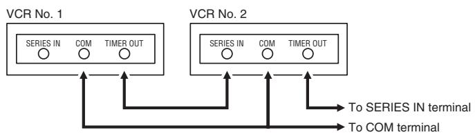
- Depending on the "EJECT MODE" setting in the (WARNING OUT/CONTROL SET) menu (see "Cassette Eject Setup"), the cassette loaded into the VCR can be ejected when there is input to this terminal.
Eject output (TIMER OUT) terminal
- A signal is output from this terminal when the EJECT button is pressed (if the VCR is set up as the "MASTER" VCR; see step ⑦ under "Cassette Eject Setup") or when there is input (a trigger) at the SERIES IN terminal, even if the security lock is set on a cassette is not loaded.
NOTES:
- The terminal names and signals are different from the usual setting.
- Names in brackets apply to terminals on the rear panel.
SYNCHRONIZATION CONTROL
When two or more VCRs are connected together, the VCRs can be operated simultaneously just by operating the VCR that has been set to "MASTER", without using a system controller (sold separately).
There are two modes available: operator mode and administrator/installer mode. The operations that can be carried out in each mode are different.
NOTES:
- The operation and setting can only be carried out with the button of this unit.
- Use cables with a thickness of A.W.G.24 (0.2 mm²) or more and a length no more than 1.5 m to connect VCRs.
- It is recommended that you do not connect any more than 10 VCRs together.
- Only one VCR can be specified at the master unit.
- Do not mix operator mode and administrator/installer mode in the same installation.
- Do not connect the VCRs in a loop.
- “TERMINAL SET” in the (OTHERS) menu should always be set to “SET1”.
- The VCR operation may not e completely synchronized depending on the VCR statuses, the operating environment and the operation timing. It is recommended that you check the operating statuses and menus after carrying out each operation.
Connection
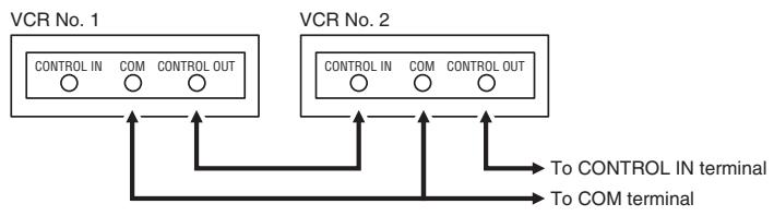
Operator Mode
This mode lets you carry out basic operations (ejecting, recording, stopping, rewinding, changing the recording speed mode and power on/stand-by).
NOTE:
-
This mode will not work correctly unless the VCRs are in the same initial state.
1 Press the STANDBY/ON button.
Press the MENU button to display the MAIN MENU.
③ Turn the JOG dial to select the "4.WARNING OUT/CONTR. SET" line, then turn the SHUTTLE ring clockwise.
-
The (WARNING OUT/CONTROL SET) menu appears.
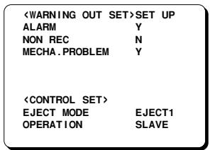
Turn the JOG dial until the "OPERATION" setting is highlighted, then turn the SHUTTLE ring clockwise.
⑤ Turn the JOG dial to select the desired operation, then turn the SHUTTLE ring clockwise.
SLAVE The function is restricted to only the VCR being operated.
MASTER The function is applied to the VCR being operated and all VCRs that are connected after it.
- When the "OPERATION" is set to "MASTER", "SC" lights on the digital display.
Press the MENU EXIT button.
SYNCHRONIZATION CONTROL
Setting the Cassette Eject Mode
Operator mode can be used to eject cassettes for all VCRs or for specified VCRs.
1 Follow steps 1 to 5 under "Operator Mode".
② Turn the JOG dial until the “EJECT MODE” setting is highlighted, then turn the SHUTTLE ring clockwise.
③ Turn the JOG dial to select the desired cassette eject mode, then turn the SHUTTLE ring clockwise.
EJECT1 . The cassette is ejected only if the VCR is not in recording or recording pause mode.
EJECT2 . The cassette is ejected only if the VCR is in stop mode.
4 Press the MENU EXIT button.
Administrator/Installer Mode
This mode lets you carry out basic operations (ejecting, recording, stopping, rewinding, changing the recording speed mode and power on/stand-by) and also make menu settings.
NOTES:
- This mode will not work correctly unless the VCRs are in the same initial state.
- Menu settings will not work correctly unless the menu settings for the VCRs are the same. Set the menu settings for each VCR to the initial setting before using this mode to change the settings.
- If a power failure occurs, make the settings again.
1 Press the STANDBY/ON button.
2 While holding the STOP button, press the STILL/PAUSE button for 3 seconds or more on the VCR that is set to be the master VCR.
° "SC" will flash on the digital display.
"SC" flashes (master) . The menu settings can be changed for the VCR being operated and all VCRs that are connected after it.
- This mode can be used regardless of the "OPERATION" setting in the (WARNING OUT/CONTROL SET) menu.
"SC" off (slave) The menu settings can be changed for only the VCR being operated.
- To cancel the master mode, press and hold the STOP button and then press the STILL/PAUSE button.
SETTING FOR RS-485 OR RS-232C USE
The RS-485 interface can be used to operate the VCR using a SANYO brand system controller. Furthermore, the RS-232C interface can be used to operate the VCR using a computer.
NOTES:
- This can only be used when the RS-485/232C interface board (VZU-485/232C) is installed.
- Refer to the instruction manuals for the VZU-485/232C, the system controller and/or the computer.
Setting the Address and Data Transfer Speed
- Make this setting without a cassette tape inserted.
1 Press the COUNTER RESET button for 3 seconds or more.
"485" or "232" appears on the digital display.
② Turn the JOG dial to select the interface being used, RS-232C or RS-485.
"232" or "485" appears on the digital display.
- When setting "232", carry out step ③ and then step ⑥.
③ Turn the SHUTTLE ring clockwise.
4 Turn the JOG dial to set the VCR address (from 000 to 127).
- The address set appears on the digital display.
⑤ Turn the SHUTTLE ring clockwise.
⑥ Turn the JOG dial to set the data transfer speed (19200, 2400, 4800, 9600).
- The data transfer speed set appears on the digital display.
When finished, Press the COUNTER RESET button.
NOTE:
- When the MENU RESET button is pressed, the setting appearing on the digital display is reset to the default setting.
Settings when using RS-485
Press the STANDBY/ON button.
Press the MENU button to display the MAIN MENU.
③ Turn the JOG dial to select the "9.OTHERS" line, then turn the SHUTTLE ring clockwise.
° The (OTHERS) menu appears.
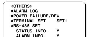
4 Turn the JOG dial until the "STATUS INFO." setting is highlighted, then turn the SHUTTLE ring clockwise.
⑤ Turn the JOG dial to set the “STATUS INFO.” setting, then turn the SHUTTLE ring clockwise.
Y. The VCR status information is output at the RS-485 connector.
N . The status information is not output at the RS-485 connector.
⑥ Turn the JOG dial until the “ALARM INFO.” setting is highlighted, then turn the SHUTTLE ring clockwise.
Turn the JOG dial to set the "ALARM INFO." setting, then turn the SHUTTLE ring clockwise.
Y. The VCR alarm information (alarm recording start and stop) and video loss information are output at the RS-485 connector.
N The VCR alarm information (alarm recording start and stop) and video loss information are not output at the RS-485 connector.
Press the MENU EXIT button.
Set the TERMINATE switch on the back panel to the "ON" or "OFF" position
OFF side . . . Not terminated
ON side . . . Terminated
NOTE:
- When a warning state (non-recording, mechanical problem or clog detection) occurs, the warning state is output from the RS-485 connector. However, non-recording warning states are not output if "NON REC" is set to "N" in the (WARNING OUT/CONTROL SET) menu. In addition, the clog detection warning state is not output if "CLOG DETECT." is set to "N" in the (GENERAL SET) menu.
CHECKING POWER FAILURE, FAILURE DUE TO CONDENSATION AND USAGE DURATION
1 Press the STANDBY/ON button.
2 Press the MENU button to display the MAIN MENU.
③ Turn the JOG dial to select the "9.OTHERS" line, then turn the SHUTTLE ring clockwise.
° The (OTHERS) menu appears.
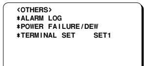
Turn the JOG dial to select the “POWER FAILURE/DEW” line, then turn the SHUTTLE ring clockwise.
- The (POWER FAILURE/DEW/USED TIME) menu appears.
Example
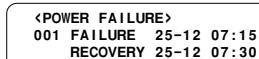
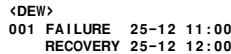
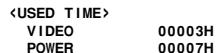
POWER FAILURE . . . The number of power failures, and the date and time of the most recent power failure and recovery are displayed.
DEW. The number of failures due to condensation, and the date and time of the most recent failure and recovery are displayed.
USED TIME . The video heads usage duration and the power on duration are displayed.
Press the MENU EXIT button.
NOTE:
- If the MENU RESET button is pressed while the "POWER FAILURE" and "DEW" data is displayed, the data is erased. The "USED TIME" data cannot be reset. "P" will be erased from the digital display.

OUTPUT TERMINALS
TAPE END OUT Terminal
- During recording, when the end of the tape is reached or when the tape counter reading indicates 3 hours, the output becomes 0V (Low). During autorepeat recording, the output becomes 0V (Low) for about 2 seconds only.
- To reset the output, press the STOP or EJECT button.
TAPE END OUT Terminal Output Setting
1 Press the STANDBY/ON button.
2 Press the MENU button to display the MAIN MENU.
③ Turn the JOG dial to select the "5.ALARM/SERIES REC SET" line, then turn the SHUTTLE ring clockwise.
- The (ALARM/SERIES REC SET) menu appears.
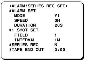
4 Turn the JOG dial until the "TAPE END OUT" setting is highlighted, then turn the SHUTTLE ring clockwise.
⑤ Turn the JOG dial to select the desired mode, then turn the SHUTTLE ring clockwise.
3:00 The output becomes 0V (Low) when the tape counter reaches "3H 00M 00S" and/or when the tape reaches the end.
END . The output becomes 0V (Low) when the tape reaches the end.
NOTES:
- If the "SERIES REC" is set to "Y" in the (ALARM/SERIES REC SET) menu, the output becomes 0V (Low) for about 2 seconds when the counter reaches "3H 00M 00S", even if the "TAPE END OUT" is set to "END".
- If the "SERIES REC" is set to "Y" in the (ALARM/SERIES REC SET) menu, the output becomes 0 V (Low) until 5 minutes have passed after the tape reaches the end.
Press the MENU EXIT button.
- Common GND (ground) terminal when connecting other terminals to external devices.
TIMER OUT Terminal
- During timer recording, the output becomes 0V .
- During timer recording stand-by mode, the output is 5 V (High).
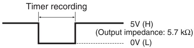
OUTPUTTERMINALS
SW OUT Terminal
When recording, a pulse signal is output at the SW OUT terminal.
This terminal is usually connected to the switch input (SW IN) of devices like a camera switcher unit, or a quad compressor.
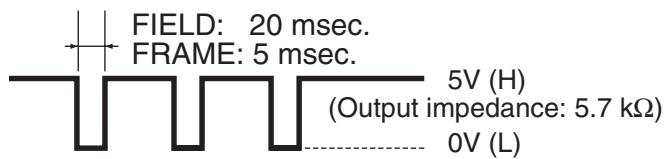
SW OUT Terminal Output Setting
1 Press the STANDBY/ON button.
Press the MENU button to display the MAIN MENU.
③ Turn the JOG dial to select the "2.DISPLAY/SW OUT SET" line, then turn the SHUTTLE ring clockwise.
° The (DISPLAY/SW OUT SET) menu appears.
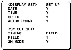
Turn the JOG dial until the "TIMING" setting is highlighted, then turn the SHUTTLE ring clockwise.
⑤ Turn the JOG dial to select the desired output timing, then turn the SHUTTLE ring clockwise.
FIELD. 1 pulse is output after each set number of fields.
FRAME 1 pulse is output after each set number of frames.
⑥ Turn the SHUTTLE ring clockwise.
7 Turn the JOG dial to select the desired pulse signal interval (1, 2, 3, 4, 5, 10, 30 or 60), then turn the SHUTTLE ring clockwise.
- If “TIMING” is set to FRAME (see step ⑤), “FRAME” will be indicated instead of “FIELD”.
⑧ Turn the SHUTTLE ring clockwise.
9 Turn the JOG dial to select the desired "3H" mode, then turn the SHUTTLE ring clockwise.
Y. When recording in 3-hour mode, a pulse signal is output.
N. When recording in 3-hour mode, a pulse signal is not output.
10 Press the MENU EXIT button.
OUTPUTTERMINALS
WARNING OUT Terminal
- The WARNING OUT terminal output becomes 0V (Low) in accordance with the (WARNING OUT/CONTROL SET) menu.
WARNING OUT Terminal Output Setting
Press the STANDBY/ON button.
Press the MENU button to display the MAIN MENU.
③ Turn the JOG dial to select the “4. WARNING OUT/CONTR. SET” line, then turn the SHUTTLE ring clockwise.
- The (WARNING OUT/CONTROL SET) menu appears.
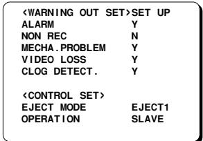
4 Turn the SHUTTLE ring clockwise.
⑤ Turn the JOG dial to select the desired mode, then turn the SHUTTLE ring clockwise.
SET UP . . . . Set each item
ALL Y.... To set all items to "Y"
ALL N.... To set all items to "N"
- If using the "SET UP" setting, continue with steps 6 to 8.
⑥ Turn the JOG dial until the item for warning output is highlighted, then turn the SHUTTLE ring clockwise.
7 Turn the JOG dial to set "Y" (warning is given) or "N" (warning is not given), then turn the SHUTTLE ring clockwise.
ALARM. The output becomes 0 V and "A" appears on the digital display during alarm recording
NON REC . The output becomes 0 V and "N" appears on the digital display if the VCR enters a mode other than recording (i.e. recording pause, stop mode, etc.) during recording
MECHA. PROBLEM . . . The output becomes 0 V and “M” appears on the digital display when the tape stops or other problem with the internal mechanism
VIDEO LOSS . . . . . The output becomes 0 V and “V” appears on the digital display when there is no video signal
CLOG DETECT. . . . The output becomes 0 V and "C" appears on the digital display when the heads are dirty and the recording quality deteriorates
Repeat steps 6 and 7 when setting other items.
When finished, press the MENU EXIT button.
NOTES:
- The "VIDEO LOSS" line does not appear if "VIDEO LOSS" is set to "N" in the (GENERAL SET) menu.
- The "CLOG DETECT." line does not appear if "CLOG DETECT." is set to "N" in the (GENERAL SET) menu.
- Displays on the digital display take precedence over other displays.
- Canceling warning displays and output. Press the STOP button once.
The warning display disappears from the digital display.
Press the STOP button once more. If "MECHA. PROBLEM" or "CLOG DETECT." warnings are being output, then output stops.
- If the "NON REC", "VIDEO LOSS" or "ALARM" warning is being output, the condition immediately before the warning output is restored and the output stops.
- If the system has shut down because of a "MECHA. PROBLEM" warning, the output is canceled when the ALL RESET button is pressed.
OUTPUTTERMINALS
REMOTE Jack
Remote control of the VCR is possible by connecting a remote controller with a circuit such as indicated below, to the REMOTE jack.
NOTES:
- Use a 3.5mm mini-jack type plug.
- The connection should be done using a shielded cable no more than 5 meters long.
- The functions not available on the VCR will not operate.
- You can use a VA-RMN01 Remote Control Unit (sold separately) to control the VCR remotely. The functions not available on the VCR will not operate.
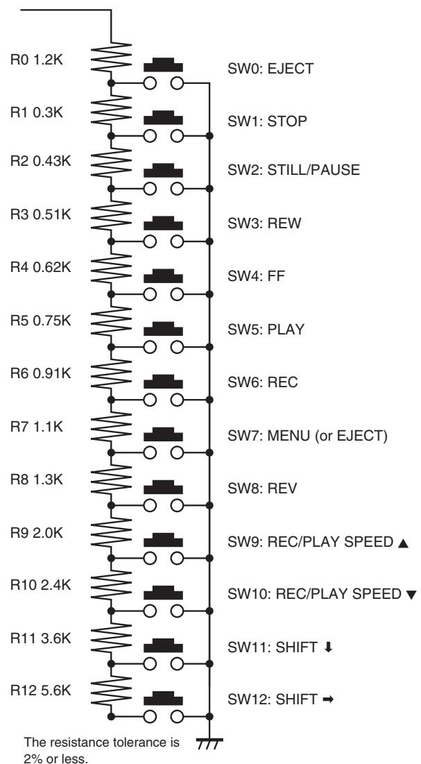
Remote control circuit
Remote control setting
The remote control switch 7 (see illustration at left) can be set to either eject the tape or access the menus.
1 Press the STANDBY/ON button.
Press the MENU button to display the MAIN MENU.
③ Turn the JOG dial to select the "3.GENERAL SET" line, then turn the SHUTTLE ring clockwise.
° The (GENERAL SET) menu appears.
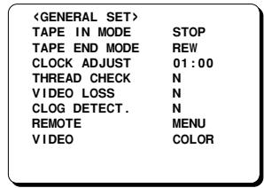
4 Turn the JOG dial until the "REMOTE" setting is highlighted, then turn the SHUTTLE ring clockwise.
⑤ Turn the JOG dial to select the desired switch mode, then turn the SHUTTLE ring clockwise.
MENU. . . . . Switch operates as an MENU button
EJECT . . . . Switch operates as an EJECT button
Press the MENU EXIT button.
HEAD SWITCHING FUNCTION
This unit is equipped with 4 double azimuth heads. Under normal conditions, recording and playback is done using the main heads “A1” and “B1”.
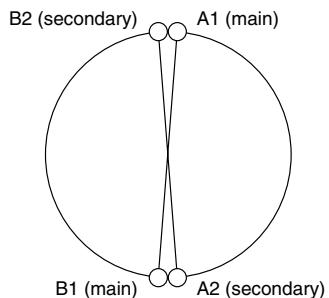
If a problem occurs with the main heads, for example if only one channel is being recorded and playback cannot be done, you can temporarily switch to the secondary heads so that the playback picture can be viewed.
(If a problem occurs with the main heads, it is recommended that you have the unit repaired as soon as possible.)
Switching heads combination and azimuth display
The heads that are used can be switched to any of the combinations (①, ② or ③) indicated in the table below, until the playback picture can be viewed. When switching to a combination other than the main heads, the corresponding azimuth indicator will be displayed.
1 Start playback.
Press and hold the MENU button, then press the PLAY button.
3 Release the button.
- The selected heads combination will change in the order indicated in the table below.
To select another head combination, repeat steps 2 and 3 above.

| Heads combination | Azimuth indicator |
| ① | A1 and A2 | + |
| ② | B1 and B2 | - |
| ③ | A2 and B2 | 1 |
| ④ | A1 and B1 | No indicator (Normal head combination) |
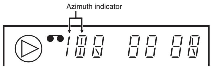
NOTES:
- When the end of the tape is reached, the head combination automatically returns to the normal setting. The head combination will also automatically return to the normal setting when the tape is stopped, the cassette is ejected or after a power interruption.
- When using the head combination ① or ② during playback, note the following points.
3-hour mode
The image is close to normal, but there will be some shaking in the vertical direction.
12 or 24-hour mode
Noise bars will be visible
48 - 960-hour mode
Noise bars will appear and disappear
Field advance
Noise bars will appear and disappear
MAINTENANCE
Daily Inspection
The following daily inspections are recommended in order to assure long-term and trouble-free operation of the unit.
The daily inspections are particularly important if using autorepeat recording.
Inspection Procedure
1 Turn on the power to the VCR, camera, TV monitor and other connected devices.
2 Check that the image received on the TV monitor is correct.
3 Check that the on-screen display of the date and time is correct.
To check the recording condition of the previous day, rewind the recorded tape a few seconds.
Press the PLAY button and check that the playback image is correct.
6 Check that the recorded date and time are correct.
NOTES:
- If the security lock is engaged, it has to be released before proceeding to the inspection.
- If any problem is discovered during the inspection, turn off the VCR, unplug the power cord then consult your dealer.
Periodic Inspection
Periodic inspection and maintenance should be referred to your dealer.
If there is noise in the playback picture, and it cannot be corrected using the tracking control, it may indicated that the video heads need cleaning.
Soiling is unlikely, thanks to the automatic head cleaning function, but due to factors such as the use of poor quality tape and the usage environment the heads could become dirty in a short time.
The video heads should be inspected every 1,000 hours of use to determine if they need to be replaced.
The video heads usage can be checked using the (POWER FAILURE/DEW/USED TIME) menu.
Cabinet Cleaning
Clean the outside of the cabinet with a clean, soft cloth, moistened with lukewarm water and wrung dry.
DO NOT USE SOLVENTS OR OTHER TYPES OF CLEANERS. THESE CHEMICALS CAN CRACK OR DISCOLOR THE CABINET.
About the Backup Battery
The date and time settings are maintained for up to 30 days by a rechargeable lithium battery that is fully charged after the VCR has been connected to a power source for 48 hours or more.
Depending on the battery usage it may become necessary to change it. For replacement and disposal of the old battery, please contact your dealer.
After the battery has been replaced, press the ALL RESET button, then enter all the time, date, etc. settings as required.
Automatic Head Cleaning Function
- Whenever a video cassette is loaded or ejected, the video heads are automatically cleaned.
- During autorepeat recording, the video heads are automatically cleaned when the tape reaches the end.
MAINTENANCE
Maintaining and Checking The Mechanism
To maintain the VCR functions and features working properly, and to avoid damages or dirt on the tape, it is recommended to follow the maintenance points and periodicity indicated below.
For detailed information, please contact your dealer.
Maintenance Table
: Cleaning : Confirmation : Lubrication : Change
| PARTS | 2000H | 4000H | 6000H | 8000H | NOTES |
| Tape Path System | ASSY, BRAKE BAND | ◎ | □ | ◎ | □ | |
| ASSY, LEVER BT (tape guide) | ○ | ○ | ○ | ○ | |
| FULL ERASE HEAD | ○ | ○ | ○ | □ | |
| ASSY, ROLLER CLEANER | ◎ | □ | ◎ | □ | |
| ASSY, GUIDE ROLLER | ○ | ○ | ○ | ○ | |
| ASSY, MOUNTING INCLNE S | ○ | ○ | ○ | □ | |
| ASSY, MOUNTING INCLNE T | ○ | ○ | ○ | □ | |
| ACE HEAD | ○ | ○ | ○ | □ | |
| ASSY, LEVER PINCH ROLLER | ○ | □ | ○ | □ | |
| MOUNTING, LIFT PINCH | | | | □ | |
| CAM, LIFT PINCH | | | | □ | |
| GEAR, CAM PINCH | | | | □ | |
| EARTH CHIP CYLINDER | | | | □ | |
| COMPL, CYLINDER | ○ | ○(□) | ○ | ○(□) | |
| ASSY, CYLINDER UPPER | ○(□) | ○(□) | ○(□) | ○(□) | |
| Reel Drive System | ASSY, REEL SUPPLY | ○△ | ○△ | ○△ | ○△ | |
| ASSY, REEL TAKEUP | ○△ | ○△ | ○△ | ○△ | |
| GEAR, REEL S | △ | △ | △ | △ | |
| GEAR, REEL T | △ | △ | △ | △ | |
| PULLEY, REEL | △ | △ | △ | △ | |
| SPECIAL, WASHER 2.4 X 6 X 0.25 | | ◎ | | ◎ | |
| COMPL, MOUNTING CLUTCH | △ | □ | △ | □ | |
| BELT, REEL | ◎ | □ | | □ | |
| MOTOR, CAPSTAN | ○ | ◎(□) | ◎(□) | □ | |
| ASSY, GEAR FRICTION | △ | △□ | △ | △□ | |
| Brake | ASSY, BRAKE S | ◎ | ◎ | ◎ | ◎ | |
| ASSY, BRAKE T | ◎ | ◎ | ◎ | ◎ | |
| ASSY, BRAKE CAPSTAN | ◎ | ◎ | ◎ | ◎ | |
| ASSY, BRAKE SOFT T | | ◎ | | □ | |
| Loading Drive System | ASSY, LOADING MOTOR | | ◎ | | □ | |
| DAMPER | | | | □ | |
| COMPL, GEAR WORM | | ◎ | | □ | |
| CAM, MAIN | | | | □ | |
| SPECIAL WASHER 3.6 X 0.5 | | ◎ | | □ | |
| GEAR, WHEEL 1 | | | | □ | |
| GEAR, WHEEL 2 | | ◎ | | □ | |
| GEAR RELAY PINCH OPT | | | | □ | |
| SLIDE, CRECENT | | ◎ | | □ | |
| GEAR, LOAD S | | ◎ | | □ | |
| GEAR, RACK FRONT | | ◎ | | □ | |
| GEAR, RACK START | | ◎ | | □ | |
| GEAR, PINON | | ◎ | | □ | |
| Performance Check | BACK TENSION TORQUE | ◎ | ◎ | ◎ | ◎ | PB BACK TENSION TORQUE 25~50g·cm |
| FWD, REW TORQUE | ◎ | ◎ | ◎ | ◎ | FWD, REW TORQUE ≥ 600g·cm |
| PLAY TORQUE | ◎ | ◎ | ◎ | ◎ | PLAY 55 ~ 110g·cm |
| REV TORQUE | ◎ | ◎ | ◎ | ◎ | REV 100 ~ 210g·cm |
NOTES:
- This table shows the maintenance for up to 8000 hours. After this, repeat from the start or the table.
- For places with symbols such as (□) and (□), carry out checking and cleaning, and replace if necessary.
- This periodic maintenance check table changes considerably according to the using conditions and environment.
Refer to the (POWER FAILURE/DEW/USED TIME) menu for the length of time the unit has been used.
- As the life of parts may be shortened if foreign particles and dusts remain accumulated on the tape guides and rotating and contacting portions, clean if dirty.
- Dusts and other foreign particles on the tape guides may also shorten the tape life and lower picture quality, therefore clean thoroughly.
TROUBLESHOOTING GUIDE
If the unit does not operate normally when you follow the instructions indicated in the manual, please refer to the table below.
| SYMPTOM | POSSIBLE CAUSE | CORRECTIVE ACTION |
| No power | The power cord is not connected | Connect the power cord |
| No image displayed on the TV monitor | The connections are not correct | Check that all connections are correct |
| The power to the camera and/or TV monitor is not turned on | Turn all connected devices power on |
| The buttons do not respond | A cassette tape is not loaded | Load a cassette and turn the power on |
| All functions are suspended due to condensation | Wait for the “d d d” indicator to go off |
| Alarm recording | Wait for the alarm recording to end |
| Unit in menu mode | Press the MENU EXIT button. |
| The security lock is engaged | Cancel the security lock |
| Recording is not possible (the tape is ejected) | The loaded cassette has no erasure-prevention tab | Load a cassette tape with an erasure-prevention tab or cover the tab hole with adhesive tape |
| Recording is not possible (Tape rewinds) | “Y” is selected for the tape management | Normally. Refer to “TAPE MANAGEMENT” on page 16. |
| Autorepeat recording is not possible | “AL” appears on the digital display | Display (ALARM LOG) menu, then press the MENU RESET button to turn off the “AL” indicator |
| Timer recording is not possible | The date and time are not set correctly | Set the date and time correctly |
| The unit is not set to timer recording stand-by mode | Press the TIMER button to display “☐” on the digital display |
| “N” is selected for the timer recordings | Be sure to select “Y” for the programmed timer recordings |
| Alarm recording is not possible | “OFF” appears on the digital display | Press the EJECT, STOP or PLAY button or turn the SHUTTLE ring to turn the indicator off |
| Noise in the playback picture | The video heads need cleaning | Clean the video heads |
| The date and time are not recorded | Display mode not set. | Press the ON SCREEN button to display and record the date and time. |
| “○” flashes. | The heads are dirty (see page 21). | Clean the heads. |
| The cassette tape cannot be ejected | Problem with the system | Unplug the power cord then plug it back in |
| The cassette is ejected a few seconds after it has been inserted | The tape is not threaded correctly | Try inserting the cassette one more time or using a new cassette. If it is ejected again, please consult your dealer. |
After a Power Failure
If the recording speed is reset to 3-hour mode after a power failure, it is due to insufficient backup battery charge. This is not a malfunction.
System Down
If the unit does not function at all, try the following.
Unplug the power cord then plug it back in.
Reset the memory. (Press the ALL RESET button. Under normal conditions, do not touch the ALL RESET button.)
The time and date will be reset, and the quick method security lock will be canceled.
3 If the problem is not corrected after performing steps
1 and 2 a few times, consult your dealer.
SPECIFICATIONS
General Specifications
| Video head system | Dual-azimuth 4-head rotating helical scanning system:
Dual azimuth 2-head for record and standard playback
Dual azimuth 4-head for forward picture search, reverse picture search
and still mode |
| Audio recording | In 3-, 12- and 24-hour modes (when using E-180 tape) |
| Tape speed | 23.39 mm /sec (3-hour mode) |
| Specified video cassette tape | VHS 1/2 inch video cassette tape |
| Recording/playback time (TLS-1960P only) | 3, 12, 24, 48, 72, 96, 120, 168, 240, 360, 480, 720 and 960 hours (when using E-180 tape) |
| Recording/playback time (TLS-9924P only) | 3, 12 and 24 hours (when using E-180 tape) |
| Fast forward/rewind time | approximately 2 minutes (when using E-180 tape) |
| Television system | PAL colour TV system |
| Video | |
| Recording method | Luminance signal: FM recording
Chrominance signal: Down-converted direct recording |
| Video input | 1 V(p-p), BNC, 75 Ω, unbalanced |
| Video output | 1 V(p-p), BNC, 75 Ω, unbalanced |
| Horizontal resolution | Black & white mode 350 line or more
Colour mode 250 line or more |
| Audio | |
| Input | -8 dBs, RCA pin jack, 27 kΩ, unbalanced |
| Output | -8 dBs, RCA pin jack, 600 Ω, unbalanced |
| Microphone input | -60 dBs, 3.5 mm mini jack, 10 kΩ, unbalanced |
| Connectors | |
| Alarm (1 shot) input | No voltage, make-contact switch input (Low input 100ms or more, Normally 5 V) |
| Control input | Key code (pulse signal) (Normally 5 V) |
| Series input | No voltage, make-contact switch input (Low input 1s or more, Normally 5 V) |
| Ext timer (alarm reset) input | No voltage, make-contact switch input (Low input 100ms or more, Normally 5 V) |
| Common | 0 V (GND) |
| Warning output | Open collector Max. 500 mA (Active Low 0 V, Normally open) |
| Control output | Key code (pulse signal) (Normally 5 V) |
| Tape end output | Open collector Max. 50 mA (Active Low 0 V, Normally open) |
| Timer output | DC 5 V, 5.7kΩ, (Low output) |
| Switch output | Pulse signal (Normally 5 V) |
| DC 12-24V “+” input (TLS-1960P only) | DC 12 to 24V |
| DC 12-24V “-” input (TLS-1960P only) | DC 0 V |
| Remote control input | 3.5 mm mini jack |
SPECIFICATIONS
Other Specifications
Operating temperature range 5°C to 40°C (41°F to 104°F)
Operating humidity range 80% or less
Power requirements (TLS-1960P only) 220-240V AC, 50Hz (or DC power: 12 to 24V DC)
Power requirements (TLS-9924P only) 220-240V AC, 50Hz
Power consumption 15 W
Dimensions (W x H x D) 420 mm x 99.5 mm x 306 mm
Weight (TLS-1960P only) approximately 4.2kg
Weight (TLS-9924P only) approximately 4.0kg
Connectors (When the "TERMINAL SET" is set to "SET2")
NOTES:
- The terminal names and signals are different from the usual setting.
- Names in brackets apply to terminals on the rear panel.
Clock set input (CONTROL IN) No voltage, make-contact switch input (Low input 100ms or more, Normally 5 V)
Clock set output (CONTROL OUT) DC 5 V, 5.7kΩ, (Low output)
Eject input (SERIES IN) No voltage, make-contact switch input (Low input 100ms or more, Normally 5 V)
Eject output (TIMER OUT) DC 5 V, 5.7kΩ, (Low output)
NOTE: The specifications and external appearance of this unit are subject to change without notice.