
Bluehelix Tech RRT 24C - Boiler FERROLI - Free user manual and instructions
Find the device manual for free Bluehelix Tech RRT 24C FERROLI in PDF.


| Product Type | Condensing Boiler |
| Model | Bluehelix Tech RRT 24C |
| Brand | Ferroli |
| Energy Source | Natural Gas / LPG (convertible) |
| Heating Output (Max) | 24 kW |
| Domestic Hot Water Output (Max) | 28 kW |
| Efficiency (Seasonal) | Up to 94% (ErP A rated) |
| Flow Temperature Range | 30 - 80 °C |
| Water Connection | 3/4" BSP |
| Gas Connection | 3/4" BSP |
| Flue Type | Room sealed (concentric) |
| Dimensions (H x W x D) | 700 x 400 x 285 mm |
| Weight (Net) | 32 kg |
| Expansion Vessel Capacity | 8 L |
| Maximum Operating Pressure | 3 bar |
| Electrical Supply | 230 V ~ 50 Hz |
| Power Consumption (Max) | 130 W |
| Control Type | Electronic PCB with LCD display |
| Outdoor Sensor | Optional (weather compensation) |
| Safety Features | Flame failure, overheat protection, frost protection, pump anti-block |
| Maintenance | Annual service recommended; accessible heat exchanger and burner |
| Spare Parts Availability | Common parts available through Ferroli network |
| Noise Level | < 45 dB(A) |
| IP Rating | IPX5 (water jets) |
Frequently Asked Questions - Bluehelix Tech RRT 24C FERROLI
User questions about Bluehelix Tech RRT 24C FERROLI
0 question about this device. Answer the ones you know or ask your own.
Ask a new question about this device
Download the instructions for your Boiler in PDF format for free! Find your manual Bluehelix Tech RRT 24C - FERROLI and take your electronic device back in hand. On this page are published all the documents necessary for the use of your device. Bluehelix Tech RRT 24C by FERROLI.
USER MANUAL Bluehelix Tech RRT 24C FERROLI
BLUEHELIX TECH RRT 24 C
ERP

natural_image
White Ferroli water heater with control panel (no visible text or symbols on body)
Type Approved Energy Efficiency Class A Regular Surveillance
www.tuv.com ID 0000058203

CE
INSTRUCTIONS FOR USE, INSTALLATION AND MAINTENANCE

- Read the warnings in this instruction booklet carefully since they provide important information on safe installation, use and maintenance.
- This instruction booklet is an integral and essential part of the product and must be kept with care by the user for future reference.
- If the unit is sold or transferred to another owner or if it is to be moved, always make sure the booklet stays with the boiler so that it can be consulted by the new owner and/or installer.
• Installation and maintenance must be carried out by professionally qualified personnel, according to current regulations and the manufacturer's instructions. - Incorrect installation or inadequate maintenance can result in damage or injury. The manufacturer declines any liability for damage caused by errors in installation and use or by failure to follow the instructions provided.
- Before carrying out any cleaning or maintenance operation, disconnect the unit from the power supply using the system switch and/or the special cut-off devices.
- In case of a fault and/or poor operation, deactivate the unit and do not try to repair it or directly intervene. Contact professionally qualified personnel. Any repair/replacement of the products must only be carried out by qualified personnel using ge-
nuine parts. Failure to comply with the above can compromise the safety of the unit.
- Periodic maintenance performed by qualified personnel is essential in order to ensure proper operation of the unit.
- This unit must only be used for its intended purpose. Any other use is deemed improper and therefore hazardous.
• After unpacking, check the good condition of the contents. The packing materials are potentially hazardous and must not be left within the reach of children.
- The unit can be used by children aged at least 8 years and by persons with reduced physical, sensory or mental capabilities, or lacking experience or the necessary knowledge, only if under supervision or they have received instructions on its safe use and the related risks. Children must not play with the unit. Cleaning and maintenance intended to be done by the user can be carried out by children aged at least 8 years only if under supervision.
- In case of doubt, do not use the unit. Contact the supplier.
- The unit and its accessories must be appropriately disposed of in compliance with current regulations.
- The images given in this manual are a simplified representation of the product. In this representation there may be slight and insignificant differences with respect to the product supplied.
| This symbol indicates “CAUTION” and is placed next to all safety warnings. Strictly follow these instructions in order to avoid danger and damage to persons, animals and things | |
| This symbols calls attention to a note or important notice. | |
| This symbol, which is used on the product, packaging or documents, means that at the end of its useful life, this product must not be collected, recycled or disposed of together with domestic waste.Improper management of electric or electronic waste can lead to the leakage of hazardous substances contained in the product. For the purpose of preventing damage to health or the environment, users are kindly asked to separate this equipment from other types of waste and to ask for it to be dealt with by the municipal waste service or dealer under the conditions and according to the methods set down in national and international laws transposing the Directive 2012/19/EU.Separate waste collection and recycling of unused equipment helps to save natural resources and to guarantee that this waste is processed in a manner that is safe for health and the environment.For more information about how to collect electric and electronic equipment and appliances, please contact your local Council or Public Authority competent to issue the relevant permits. |

The CE marking certifies that the products meet the essential requirements of the relevant directives in force.
The declaration of conformity may be requested from the manufacturer.
COUNTRIES OF DESTINATION: GB
1 Operating instructions .... 4
1.1 Introduction......4
1.2 Control panel 4
1.3 Connection to the power supply, switching on and off 5
1.4 Adjustments....6
2 Installation....10
2.1 General Instructions .... 10
2.2 Place of installation 10
2.3 Plumbing connections 10
2.4 Gas connection 12
2.5 Electrical connections....12
2.6 Fume ducts....14
2.7 Condensate drain connection....20
3 Service and maintenance....21
3.1 Adjustments....21
3.2 Commissioning....32
3.3 Maintenance....33
3.4 Troubleshooting....42
4 Technical data and characteristics .... 45
4.1 Dimensions and connections ...... 45
4.2 General view 47
4.3 Hydraulic circuit 47
4.4 Technical data table 48
4.5 Diagrams 50
4.6 Wiring diagram 50
1. 39Operating instructions
1.1 Introduction
Dear Customer,
BLUEHELIX TECH RRT 24 C is a high-efficiency, low emissions premix condensing heat generator with a stainless steel heat exchanger and incorporated DHW production, using natural gas or LPG and equipped with a microprocessor control system.
The sealed chamber unit is designed for indoor installation with temperatures as low as -5^ (-15°C with optional anti-freeze kit).
1.2 Control panel

fig. 1- Control panel
Panel legend fig. 1
1 DHW temperature setting decrease button
2 DHW temperature setting increase button
Indication during operation
Heating
A heating demand (generated by the Room Thermostat or Remote Timer Control) is indicated by the activation of the radiator symbol (detail 13 - fig. 1).
The display (detail 12 - fig. 1) shows the actual heating flow temperature and after the heating demand a standby or delay time message "d2" appears (see fig 2).
Domestic hot water (DHW)
A DHW demand (generated by drawing hot water) is indicated by the activation of the tap symbol (detail 9 - fig 1).
The display (detail 12 - fig. 1) shows the actual DHW outlet temperature and after the DHW a standby or delay time message "d1" appears (see fig 3.).
3 Heating system temperature setting decrease button
4 Heating system temperature setting increase button
5 Display
6 Reset button - Outside Temperature Compensation
7 Mode selection button: "Winter", "Summer", "Unit OFF", "ECO", "COMFORT"
8 Eco (Economy) or Comfort mode
9 DHW demand
10 Summer mode
12 Multifunction display (flashing during exchanger protection function)
13 Heating demand
14a Burner lit (flashing during calibration function and self-diagnosis phases)
14b Appears when a fault has occurred causing the unit to shut down. To restore unit operation, press the RESET button (detail 6)
17 External sensor detected (with optional external probe)


fig. 2


fig. 3
Comfort
A Comfort demand (reinstatement of temperature inside the boiler) is indicated by flashing of the Comfort symbol. The display (detail 12 - fig. 1) shows the actual temperature of the water within the boiler.
Fault
In case of a fault (see cap. 3.4 "Troubleshooting") the display shows the fault code (detail 12 - fig. 1) and during safety pause times the messages "d3" or "d4" will be displayed.
1.3 Connection to the power supply, switching on and off
Boiler not electrically powered

To avoid damage caused by freezing during long idle periods in winter, it is advisable to install an external frost protection kit & ensure the Gas, water & power supplies are maintained correctly.

fig. 4- Boiler not electrically powered
Boiler electrically powered
Switch on the power to the boiler (Max 3 amp switched fused spur supply at 230v a.c)..

fig. 5- Switching on / Software version

fig. 6- Vent with fan on

fig. 7- Vent with fan off
- During the first 5 seconds the display shows the P.C.B software version (fig. 5).
- For the following 20 seconds the display will show FH which Indicates the heating system air venting cycle with the fan operating (fig. 6). The internal pump will cycle on & off during this period.
• In the next 280 seconds, the venting cycle continues with the fan off (fig. 7) & again the pump will cycle on & off. - Open the gas isolation valve under the boiler
- When the message Fh disappears, the boiler is ready to operate automatically whenever domestic hot water is drawn or there is a heating demand.
Electronically turning the boiler off and on
To switch modes, press the winter/summer/off button, for about 1 second, in the order indicated in fig. 8.
A = Winter Mode (Heating & hot water) Heating via external controls i.e time clock & room thermostat.
B = Summer Mode (Hot water only)
C = Off Mode (Boiler frost protection only no heating or hot water) services must be maintained.
To turn the boiler off, press the winter/summer/off button (detail 7 - fig. 1) repeatedly until the display shows dashes.

flowchart
graph LR
    A["eco 60°C"] --> B["eco 28°C"]
    B --> C["--"]
    style A fill:#f9f,stroke:#333
    style B fill:#ccf,stroke:#333
    style C fill:#cfc,stroke:#333
fig. 8- Turning the boiler off
When the boiler is turned off, the printed circuit board is still powered. Domestic hot water and heating are disabled. The frost protection system remains activated. To operate the boiler normally, press the winter/summer/off button (detail 7 - fig. 1) twice.

fig. 9
The boiler will be immediately ready in Winter and DHW mode.

The frost protection system does not work when the power and/or gas to the unit are turned off. In winter to avoid damage to the entire system caused by freezing during long periods of shutdown, it is advisable to fit an external frost protection kit..
NOTE - If the sun symbol does not appear on the display but the multifunction numbers are present, the boiler is in "Winter" mode.
1.4 Adjustments
Winter/summer switchover
Press the winter/summer/off button (detail 7 - fig. 1) until the display shows the Summer symbol (detail 10 - fig. 1): the boiler will only deliver domestic hot water. The frost protection system remains activated.

fig. 10
To reactivate the Winter mode, press the winter/summer/off button (detail 7 - fig. 1) twice.
NOTE:- Do not hold the winter/summer/off button "in" as you will enter the OTC zone mode & the screen will display as shown should this occur please press & hold the winter/summer/off button until the display returns to its normal mode.
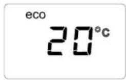
fig. 11
Heating temperature adjustment
Use the heating buttons (details 3 and 4 - fig. 1) to adjust the temperature from a min. of 20°C to a max. of 75°C.
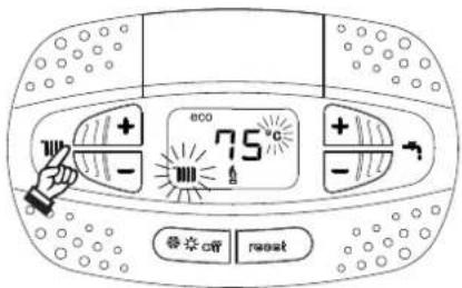
fig. 12
DHW temperature adjustment
Use the DHW buttons (detail 1 and 2 - fig. 1) to adjust the temperature from a min. of 40°C to a max. of 55°C.

If a small amount of water is drawn and/or with an increased cold water inlet temperature, then the DHW outlet temperature may vary from the actual set-point temperature.
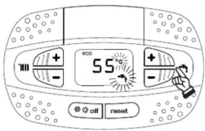
fig. 13
Room temperature adjustment (with optional room thermostat)
Using a room thermostat, or programmable room thermostat set the temperature required in the rooms. (The use of a room thermostat / programmable thermostat is mandatory as per the Building regulations part L).
Room temperature & time adjustment (with optional room thermostat)
Using the remote timer control, set the required temperature in the rooms. The boiler will adjust the system water according to the required room temperature. For operation with remote timer control, please refer to the relevant instruction manual.
ECO/COMFORT selection
The unit has a function that ensures a quick domestic hot water delivery rate to ensure maximum comfort for the user. When the device is activated (COMFORT mode), the water contained within the boiler is kept warm, therefore ensuring a faster response for hot water upon opening a domestic hot tap or shower.
The device can be deactivated by the user (ECO mode) by pressing the winter/summer/off button (detail 7 - fig. 1) for 5 seconds. In ECO mode the display activates the ECO symbol (detail 12 - fig. 1). To activate the COMFORT mode, press the winter/summer/off button again (detail 7 - fig. 1) for 5 seconds.
Outside Temperature Compensation (OTC)
When the optional external sensor is installed the boiler adjustment system works with "OTC". In this mode, the heating system temperature is regulated according to weather conditions, to ensure a high comfort and energy efficiency throughout the year. In particular, as the outside temperature increases the system flow temperature decreases according to a specific "compensation curve".
With the "OTC" adjustment, the temperature set with the heating buttons (detail 3 - fig. 1) becomes the maximum system flow temperature. It is advisable to set a maximum value to allow system adjustment throughout its useful operating range.
The boiler must be adjusted at the time of installation by fully trained personnel. However, the user can make any further adjustments necessary to optimise comfort levels.
Compensation curve and curve offset
Press the reset button (detail 6 - fig. 1) for 5 seconds to access the "OTC" menu; the display shows "CU" flashing.
Use the DHW buttons (detail 1 - fig. 1) to adjust the desired curve from 1 to 10 according to the characteristic (fig. 14). By setting the curve to 0, the "OTC" adjustment is disabled.
Press the heating buttons (detail 3 - fig. 1) to access parallel curve offset; the display shows "OF" flashing. Use the DHW buttons (detail 1 - fig. 1) to adjust parallel curve offset according to the characteristic (fig. 15).
Press the heating buttons (detail 3 - fig. 1) to access the menu "shutdown for external temperature"; the display shows "SH" flashing. Use the DHW buttons (detail 1 - fig. 1) to adjust the shutdown external temperature. If set to 0 the function is disabled; the range varies from 1 to 40^ . The boiler will ignite when the external probe temperature is 2^ lower than the set temperature.
Press the reset button (detail 6 - fig. 1) again for 5 seconds to exit the "OTC" menu.
If the room temperature is lower than the required value, it is advisable to set a higher value curve and vice versa. Proceed by increasing or decreasing in steps of one and check the result in the room before any further adjustments.

line
| Outside Air temperature | Maximum boiler flow temperature (Line 1) | Maximum boiler flow temperature (Line 2) | Maximum boiler flow temperature (Line 3) | Maximum boiler flow temperature (Line 4) | Maximum boiler flow temperature (Line 5) | Maximum boiler flow temperature (Line 6) | Maximum boiler flow temperature (Line 7) | Maximum boiler flow temperature (Line 8) | Maximum boiler flow temperature (Line 9) | Maximum boiler flow temperature (Line 10) | | ------------------------ | ---------------------------------------- | ---------------------------------------- | ---------------------------------------- | ---------------------------------------- | ---------------------------------------- | ---------------------------------------- | ---------------------------------------- | ---------------------------------------- | ---------------------------------------- | ----------------------------------------- | | 20 | 30 | 30 | 30 | 30 | 30 | 30 | 30 | 30 | 30 | 30 | | 10 | 35 | 40 | 45 | 50 | 55 | 60 | 65 | 70 | 75 | 80 | | 0 | 40 | 45 | 50 | 55 | 60 | 65 | 70 | 75 | 80 | 85 | | -10 | 45 | 50 | 55 | 60 | 65 | 70 | 75 | 80 | 85 | 90 | | -20 | 50 | 55 | 60 | 65 | 70 | 75 | 80 | 85 | 90 | 95 |fig. 14- Compensation curves

line
| x | y | |----|------| | 0 | 20 | | -10| 30 | | -20| 40 | | -30| 50 | | -40| 60 | | -50| 70 | | -60| 80 | | -70| 90 | | -80| 100 |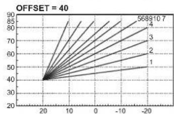
line
| x | y | | ---- | ---- | | 20 | 40 | | 10 | 60 | | 0 | 70 | | -10 | 80 | | -20 | 90 |fig. 15- Example of compensation parallel curve offset
Adjustments from Remote Timer Control

If the boiler is connected to the Remote Timer Control (optional) with OpenTherm protocol, the previously described adjustments can be made as described table 1.
Table. 1
| Heating temperature adjustment | Adjustment can be made from the Remote Timer Control menu and the boiler control panel. |
| DHW temperature adjustment | Adjustment can be made from the Remote Timer Control menu and the boiler control panel. |
| Summer/Winter Switchover | Summer mode has priority over a possible Remote Timer Control heating demand. |
| Eco/Comfort selection | On disabling DHW from the Remote Timer Control menu, the boiler selects Economy mode. In this condition, the eco/comfort button on the boiler panel is disabled. |
| By enabling DHW from the Remote Timer Control menu, the boiler selects Comfort mode. In this condition it is possible to select one of the two modes on the boiler panel. | |
| Outside Weather Compensation | You can make all the adjustments by using the remote timer control. |
System draining
The drain tap ring nut is located under the safety valve inside the boiler.
To drain the boiler turn off the supplied isolation valves underneath, then turn the ring (ref. 1 - fig. 17) anticlockwise to open the tap. Do not use any tools; use hands only.

fig. 16- Safety valve with built in drain tap
2. Installation
2.1 General Instructions

This unit must only be used for its intended purpose. This unit is designed to heat water to a temperature below boiling point and must be connected to a heating system and/or a water supply system for domestic use, compatible with its performance, characteristics and heating capacity. Any other use is deemed improper.
THE BOILER MUST ONLY BE INSTALLED BY QUALIFIED PERSONNEL, IN COMPLIANCE WITH ALL THE INSTRUCTIONS GIVEN IN THIS TECHNICAL MANUAL, THE PROVISIONS OF CURRENT LAW, THE REQUIREMENTS OF THE TECHNICAL STANDARDS (BS) AND ANY LOCAL REGULATIONS AND THE RULES OF PROPER WORKMANSHIP.
Incorrect installation can cause damage or injury for which the manufacturer cannot be deemed responsible.
The unit must be installed in compliance with these instructions and the following standards applicable in Great Britain.
Gas Safety Regulations (Installations & Use).
Local Building Regulations.
The Building Regulations (Part L).
The Buildings Standards (Scotland - Consolidated) Regulations). British Standards Codes of Practice (BSI):
The Industry Guidance For Installers On Condensate Drainage Pipe Installation (HHIC)
B.S. 5440 Part 1 Flues
B.S. 5440 Part 2 Air flow and ventilation
B.S. 5449 ...... Forced circulation hot water production systems
B.S. 6798 ...... Installation of gas-fired boilers for hot water
B.S. 6891 ...... Gas systems
B.S. 7671 ...... IEE wiring system standards
B.S. 4814 ...... Specifications for expansion tanks
B.S. 5482 ..... LPG systems
B.S. 7593 ...... Water treatment in central heating systems for DHW production
B.S. 5546 ...... Installation of systems for DHW production
B.S. 7967 ...... Guide for the use of electronic portable combustion gas analysers
Model Water By-Laws (Great Britain)
B.S. 5955-8 ...... Installation of plastic pipes
For Northern Ireland the relevant laws in force must be observed.
Safe handling of materials
Pay attention when handling the boiler insulation panels as they contain materials that could irritate the skin. No part of the boiler contains asbestos, mercury or CFC's.
The use Personal Protective Equipment (PPE) is always recommended.
Advice for transport and handling
For lifting and transporting always take suitable safety precautions: keep your back straight, bend knees, do not turn your body, move feet, avoid bending forward or sideways and keep the load as close as possible to your body.
If possible, use a trolley or other suitable means to carry the boiler.
Grip the boiler firmly and, before lifting it, try and find the point where the load is concentrated in order to establish the centre of gravity and suitably reposition yourself. Ideally seek assistance in lifting the boiler.
2.2 Place of installation
The combustion circuit is sealed with respect to the place of installation and therefore the unit can be installed in any room. However, the place of installation must be sufficiently ventilated to prevent the creation of dangerous conditions in case of even slight gas leaks. This safety regulation is provided for by EEC Directive no. 90/396 for all gas units, including those with a sealed chamber.
In any case, the place of installation must be free of dust, flammable materials or objects or corrosive gases.
The boiler is arranged for wall mounting and comes standard with a hanging bracket. A paper template for marking the drilling points on the wall is provided in the box. The wall fixing must ensure stable and effective support for the boiler.

If the unit is enclosed in a cabinet or mounted alongside, a space must be provided for removing the casing and for normal maintenance operations. The minimum measurements to be respected are given in fig. 17.

fig. 17 - Minimum distances around the boiler
A Min. 2,5 cm
B Min. 20 cm
C Min. 30 cm
D Min. 60 cm (via an openable panel)
2.3 Plumbing connections
Important
The heating capacity of the boiler must be previously established by calculating the building's heat requirement according to the current regulations. To ensure proper operation and long boiler life, the plumbing system must be adequately sized and complete with all the necessary accessories, including a room thermostat, a thermostatic radiator valve (TRV), etc. The system flow and return pipes must have a diameter of at least 22 mm for the first 3 m of length from the unit.
If the system delivery and return pipes follow a path where air pockets could form in certain places, it is advisable to install vent valves at these points. Also, install type "A" drain cocks at the lowest points in the system to allow complete emptying.
The temperature drop between the delivery manifold and the return to the boiler should not exceed 20 °C.
A flow rate of at least 6 litres/min through the heat exchanger is required.

Do not use the water system pipes to earth electrical appliances.
Before installation, carefully flush all the heating system pipes to remove any residuals or impurities that could affect proper operation of the unit (as required by BS 7593 Building regs Doc L).

The safety valve discharge must be connected to a 15 mm diameter copper pipe descending from the boiler to run off system water in case of overpressure in the heating circuit. Otherwise, the boiler manufacturer cannot be held liable if the discharge valve operates and floods the room. The discharge must be run to the outside of the building to prevent the risk of damage or injury caused by discharged hot water in case of overpressure in the system.
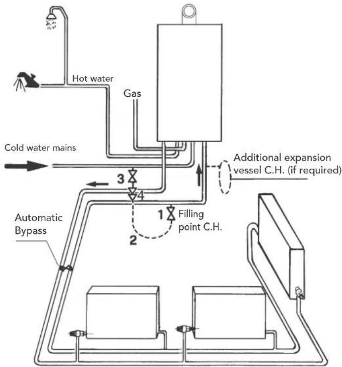
Typical System By-pass layout
flowchart
graph TD
    A["Hot water"] --> B["Gas"]
    B --> C["Cold water mains"]
    C --> D["Automatic Bypass"]
    D --> E["1 Filling point C.H."]
    E --> F["2"]
    F --> G["3"]
    G --> H["4"]
    H --> I["Additional expansion vessel C.H. (if required)"]
    style A fill:#f9f,stroke:#333
    style B fill:#ccf,stroke:#333
    style C fill:#cfc,stroke:#333
    style D fill:#fcc,stroke:#333
    style E fill:#cff,stroke:#333
    style F fill:#ffc,stroke:#333
    style G fill:#cfc,stroke:#333
    style H fill:#fcc,stroke:#333
    style I fill:#ffc,stroke:#333
fig. 18
The automatic by-pass must be installed a least 3 metres from the boiler & set to allow a minimum of 6 ltr/min through the valve when all TRV's are closed.
Make up water
Provision must be made for replacing water lost from the sealed system. Reference should be made to BS6798, for methods of filling and making up sealed systems. There must be no direct connection between the boiler's central heating system and the mains water supply. The use of mains water to charge and pressurise the system directly, is conditional upon the Local Water Byelaws. Again any such connection must be disconnected after use. Ensure the filling point is on the return pipe to the boiler.
Attention - is drawn to the Model Water Byelaws.
Filling Loop in fig. 19 is supplied with boiler.
Key
- C.H. filling valve
- Temporary connection
- Cold water supply valve
- Double check valve

fig. 19 - Filling Loop (supplied with boiler)
The maximum domestic water pressure for the inlet supply is 9 bar (130 P.S.I.). If the cold mains supply exceeds 5 bar (72 P.S.I.), a water governor or pressure reducing valve must be fitted by the installer into the mains supply in an inconspicuous but accessible position preferably between 3 and 5 metres (10-16ft) before the appliance. Such a valve must be approved by WRAS. The fitting of a DHW expansion vessel is also recommended.
Isolation valve kit
The isolation valves supplied (see fig. 20) must be installed between the boiler and heating system to allow the boiler to be isolated from the system if necessary.
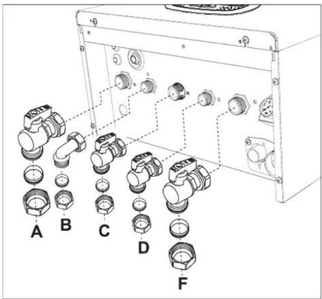
fig. 20 - Isolation valve kit
A Heating Flow 3/4" (22mm with isolation valve fitted)
B DHW outlet elbow 1/2" (15mm with outlet union fitted)
C Gas 3/4" (22mm with yellow isolation valve fitted)
D Cold water inlet 1/2" (15mm with isolation valve fitted)
F Heating Return 3/4" (22mm with isolation valve c/w filter fitted)
Important

Connections to the boiler must be made in such a way as to ensure that its internal pipes and fittings are free of stress. If a pressure reducing valve C/W non-return is installed to the boilers cold water supply it must be situated at least 3 metres from the boiler or a mini expansion vessel suitable for potable water, & correctly sized, may be used.

Before installation, flush all the pipes of the system thoroughly to remove any residuals or impurities that could affect correct operation of the unit.
In case of replacement of boiler within existing installations, the system must be completely emptied and cleaned of any sludge and pollutants. For that purpose only use suitable guaranteed products for heating systems (see next section), that do not harm metals, plastics or rubber. The manufacturer declines any liability for damage caused to the boiler by failure to clean the system to BS7593 & correctly dose with an approved inhibitor.
Make the connections to the respective points (see fig. 20 and fig. 56) as per the symbols on the bottom of the unit.
Antifreeze system, antifreeze fluids, additives and inhibitors
When necessary, antifreeze fluids, additives and inhibitors can be used only if the manufacturer of such fluids or additives guarantees that they are suitable and will not cause damage to the heat exchanger or other components and/or materials within the boiler and system. Any products used must be suitable & approved for use within a domestic heating system & noted within the benchmark certificate, a suitable label must be attached to the boiler indicating the products used & any COSH advisory information, a warning stating "Do Not Drain" must also be on the label.
System water characteristics
BLUEHELIX TECH RRT 24 C boilers are suitable for sealed systems only.
The water within a heating system must have the characteristics required by UNI 8065, and comply with laws and regulations in force and the provisions of EN14868 (protection of metallic materials against corrosion).
The return water from the heating system should have a "magnetic type filter" fitted to prevent any magnetite from entering the pump assembly or heat exchanger
The filling water (first filling and subsequent replenishment) must be clear, with hardness below 120ppm / mg/litre and treated with suitable chemical conditioners against the initiation of corrosion, that are not aggressive on metals and plastics, do not develop gases, in low-temperature systems, & do not cause proliferation of bacterial or microbial masses.
The water in the system must be periodically checked at least once a year with the annual boiler service. The water should possibly have a clear appearance, & a hardness level below 60ppm for new systems and below 80ppm for existing systems, pH above 7 and below 8.5, iron content (Fe) below 0.5 mg/l, copper content (Cu) below 0.1 mg/l, chloride content below 50mg/l, electrical conductivity below 200 s/cm, and must contain chemical conditioners in a concentration sufficient to protect the system for at least one year. Bacterial or microbial loads must not be present in low temperature systems
Recommended chemical conditioners:
SENTINEL X100 Inhibitor and SENTINEL X300 Cleaner
FERNOX F1 Inhibitor and FERNOX F3 Cleaner
SCALEMASTER SM-1 or SM-Pro Inhibitor and SM-3 or SM-Pro Cleaner
The unit is equipped with a frost protection system that activates the boiler in heating mode when the system flow water temperature falls below 6^ C. The device is not active if the power and/or gas supply to the unit has been isolated. If necessary, for system protection use a suitable antifreeze liquid that meets the same requirements as detailed above and written in Standard UNI 8065.
The presence of deposits on the boilers heat exchange surfaces due to non-compliance with the above requirements will invoke the remainder of the warranty.
2.4 Gas connection

Before making the connection to the Gas supply pipework, ensure that the appliance is suitable & labelled for operation with the type of fuel available.
The gas must be connected to the corresponding union (see fig. 20 - C & fig. 56 - 7) in conformity with current regulations, with a rigid metal copper pipe, installing the supplied Gas isolation valve between the system and boiler. Make sure that all the gas connections are tightness tested. To prevent the risk of fire or explosion.
2.5 Electrical connections
IMPORTANT

BEFORE CARRYING OUT ANY OPERATION THAT REQUIRES REMOVING THE CASING, DISCONNECT THE BOILER FROM THE ELECTRIC MAINS WITH THE MAIN SWITCH.
NEVER TOUCH THE ELECTRICAL COMPONENTS OR CONTACTS WITH THE MAIN SWITCH TURNED ON! DANGER OF ELECTRIC SHOCK WITH RISK OF INJURY OR DEATH!

The unit must be connected to an efficient Earthing system in accordance with applicable safety regulations. Have the efficiency and suitability of the Earthing system checked by professionally qualified personnel; the Manufacturer declines any liability for damage caused by failure to earth the system.
The boiler is prewired and provided with a three core cable, for connection to the electrical supply. The connection to the supply must be made permanent with a double pole switched fused spur with a minimum contact opening of at least 3 mm, a maximum fuse of rating of 3A in the Live side of the switch to the boiler. Ensure the polarities are correct (LIVE: brown wire / NEUTRAL: blue wire / EARTH: yellow-green wire in the connections to the power supply.

The boiler's supply cable MUST NOT BE REPLACED BY THE USER If the cable gets damaged, turn the boiler off and have the cable replaced only by professionally qualified personnel. In case of replacement, only use cable type "HAR H05 VV-F" 3x0.75 mm2 with max. external diameter of 8 mm. Do not splice into the existing power cable supply for another control device as this will void any remaining warranty with the boiler & may render the appliance unsafe to work on or use.
Room thermostat (optional)

IMPORTANT: THE ROOM THERMOSTAT MUST HAVE VOLTAGE-FREE CONTACTS ONLY. CONNECTING 230V TO THE ROOM THERMOSTAT TERMINALS WILL PERMANENTLY DAMAGE THE PCB.
When connecting a time control or timer, the power supply can be taken from the back of the PCB housing, see fig 20. or with the supplied batteries if required (design specific).
The room thermostat connections fig 20 Item 72 is also OpenTherm compliant this can be used to connect any of our OpenTherm controls.
Accessing the electrical terminal block and fuse
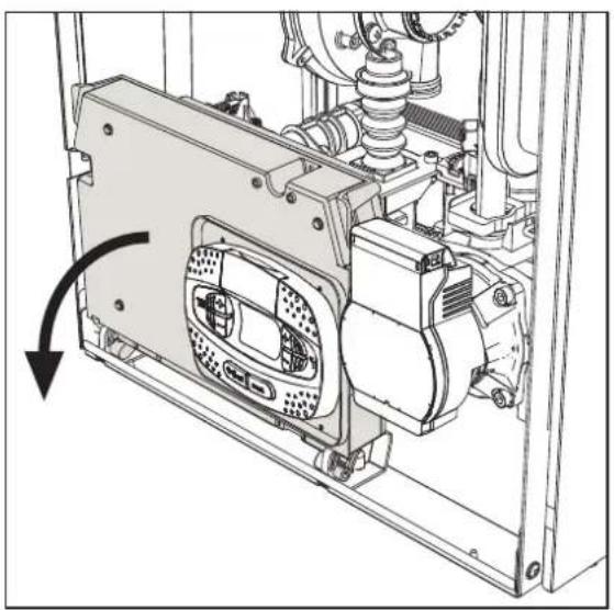
Remove the front panel ("Opening the front panel" on page 33) to access the terminal block (M) and fuse (F) by proceeding as follows (fig. 21 and fig. 22). The terminals indicated in fig. 22 must be with voltage-free contacts (not 230V). The arrangement of the terminals for the various connections is also given in the wiring diagram in fig. 60.
NOTE - The terminals 14 &15 are 230v Live & Neutral to power an external clock if required (Optional extra).
Ferroli OpenTherm RF Smart Control (option) part number Y87RFC2124 should be connected to terminals 5 & 6 (see 139 fig. 22 below) It does not require a 230v connection
natural_image
Technical line drawing of a mechanical assembly with a rotating component and housing (no text or symbols)fig. 21

A On/Off switch (option) configurable
138 Outside sensor (option) see OTC section
139 OpenTherm room timer connection (option)
72 Programmable room thermostat (option)
14 & 15 230v supply for external controls (option)
fig. 22
2.6 Flue ducts

THE BOILER MUST BE INSTALLED IN PLACES THAT MEET THE FUNDAMENTAL REQUIREMENTS FOR VENTILATION. OTHERWISE THERE IS A DANGER OF SUFFOCATION OR INTOXICATION.
READ THE INSTALLATION AND MAINTENANCE INSTRUCTIONS BEFORE INSTALLING THE UNIT.
ALSO FOLLOW THE DESIGN INSTRUCTIONS.
IN CASE OF PRESSURES ABOVE 200 Pa INSIDE THE FUME EXHAUST PIPES, CLASS "H1" FLUES MUST BE USED.
Important
The unit is "type C" with a sealed chamber and forced draught; the air inlet and flue outlet must be connected to one of the following extraction/suction systems. Before installation, check and carefully observe the above descriptions.
The positioning of wall and/or roof terminals and the minimum distances from windows, walls & ventilation outlets must be adhered to as per BS5440.
Connection with concentric chimney flues

flowchart
graph TD
    A["C1x"] --> B["C3x"]
    B --> C["C3x"]
    C --> D["C3x"]
    D --> E["C3x"]
    E --> F["C1x"]
    F --> G["C1x"]
    G --> H["C1x"]
    style A fill:#f9f,stroke:#333
    style B fill:#f9f,stroke:#333
    style C fill:#f9f,stroke:#333
    style D fill:#f9f,stroke:#333
    style E fill:#f9f,stroke:#333
    style F fill:#f9f,stroke:#333
    style G fill:#f9f,stroke:#333
    style H fill:#f9f,stroke:#333
fig. 23 - Examples of connection with concentric chimney flues ( = Air / = Frames)
Table. 2- Max. length concentric chimney flues
| Concentric 60/100 Concentric 80/125 | ||
| Max. permissible length (horizontal) 7 m | 28 m | |
| Max. permissible length (vertical) 8 m | ||
| Reduction factor 90° bend 1 m 0.5 m | ||
| Reduction factor 45° bend 0.5 m 0.25 m | ||
For concentric flue installations, you must use one of the following appliance adaptors. For the wall hole dimensions, refer to the dimensions on the template or refer to Section 4 Technical data & characteristics. Any horizontal sections of the flue must slope slightly back towards the boiler to prevent any condensate causing a nuisance from dripping out the flue terminal.
NOTE: The flue terminal length must be sealed both inside & out through the external wall with a suitable sand & cement mix.

fig. 24- Appliance adaptors for concentric chimney flues
Connection with 80mm Twin pipes

fig. 25- Examples of connection with Twin pipe system (Air / = Boxes)
Table. 3 - Examples & Classification
| Type Description | |
| C1X | Wall horizontal exhaust and intake. The inlet/outlet terminals must be together on the same wall to ensure they are in the same pressure zone. The terminals should protrude a maximum of 15cm from the wall, with a max 50cm separation (min 15cm) |
| C3X | Roof vertical exhaust and intake. The inlet/outlet ducts are combined within the room sealed vertical flue terminal. |
| C5X | Wall or roof exhaust and intake separate or in areas with different pressures. The exhaust and intake must be positioned on the same facing elevation of the building & not opposite to each other. |
| C6X Intake and exhaust with separately certified pipes (EN 1856/1) | |
| B2X | Intake from installation room or compartment utilising wall or roof flue terminal options.⚠ IMPORTANT - THE ROOM MUST BE PROVIDED WITH APPROPRIATE VENTILATION FOR COMBUSTION PURPOSES |
Twin flue appliance adaptor, to facilitate the use of the separate 80mm flue & 80mm air ducts:

fig. 26- Twin flue appliance adaptor for separate ducts
Before installation, make sure the maximum permissible length has not been exceeded, by means of a simple calculation:
- Establish the layout of the proposed the twin pipe system, including any accessories and outlet terminals.
- Consult table 5 and identify the losses in meq (equivalent metres) for each & every component.
- Check that the sum of total losses is less than or equal to the maximum permissible length in table 4.
Table. 4- Max. length separate ducts
| Max. permissible length | 80 m_eq |
Table. 5- Accessories
| Losses in m_eq | ||||||
| Air intake | Fume exhaust | |||||
| Vertical Horizontal | ||||||
| ∅ 80 | PIPE | 1 m M/F 1KWMA83W 1.0 1.6 2.0 | ||||
| BEND | 45° M/F 1KWMA65W 1.2 1.8 | |||||
| 90° M/F 1KWMA01W 1.5 2.0 | ||||||
| PIPE SECTION | with test point 1KWMA70W 0.3 0.3 | |||||
| TERMINAL | air, wall 1KWMA85A 2.0 | - | ||||
| fumes, wall with antiwind | 1KWMA86A | - | 5.0 | |||
| FLUE | Fume outlet only ∅80 | 010036X0 + 1KWMA86U | - | 4.0 | ||
 | ATTENTION: CONSIDER THE HIGH PRESSURE LOSSES OF ∅50 and ∅60 ACCESSORIES; USE THEM ONLY IF NECESSARY AND AT THE LAST FUME EXHAUST SECTION. | |||||
Connection to collective flues

fig. 27- Examples of connection to collective flues (≡ Air / = Frames)
Table. 6 - Examples & classification
| Type | Description |
| C2X | Intake and exhaust in common flue (intake and exhaust in same flue) |
| C4X | Intake and exhaust in common and separate flues, but undergoing similar pressure zones |
| C8X | Exhaust in single or common flue and wall air intake |
| B3X | Intake from installation room by means of concentric duct (that encloses the exhaust) and exhaust in common flue with natural draughtIMPORTANT- THE ROOM MUST BE PROVIDED WITH APPROPRIATE VENTILATION FOR COMBUSTION PURPOSES |
If the boiler is to be connected BLUEHELIX TECH RRT 24 C to a collective flue or to a single flue with natural draught, the flue or chimney must be expressly designed by professionally qualified technical personnel in conformity with the current regulations and be suitable for room sealed fan assisted boilers.
Backflow preventer valve
The boiler BLUEHELIX TECH RRT 24 C is equipped as standard with a backflow preventer valve (anti-backflow system), therefore it can be connected to a positive pressure collective flue system, only if using G20 gas.
Position of terminals

fig. 28
| Minimum dimensions of fume exhaust terminals | ||
| A Directly under an opening, air inlet, openable window, etc. 300 mm | ||
| B Above an opening, air inlet, openable window, etc. 300 mm | ||
| C Horizontally to an opening, air inlet, openable window, etc. 300 mm | ||
| D Under gutters, drain pipes 75 mm | ||
| E Under cornices or under eaves 200 mm | ||
| F Under balconies or garages 200 mm | ||
| G From a drain pipe or a vertical drain pipe 150 mm | ||
| H From an internal or external corner 100 mm | ||
| I Above ground level, a roof or balcony 300 mm | ||
| J | From a surface facing the terminal | 600 mm |
| K | From a terminal facing the terminal | 1200 mm |
| L | From a garage opening (e.g. door, window) with access to the home | 1200 mm |
| M | Vertically from a terminal on the same wall | 1500 mm |
| N Horizontally from a terminal on the same wall 300 mm | ||
| O | From the wall on which the terminal is fitted | N/A |
| P | From a vertical structure on the roof | 150 mm |
| Q | Above the intersection with the roof | 300 mm |
| NOTES | • N/A = Not applicable• Also, the terminal must be at least 150 mm (fanned draught) from an opening made in the structure of the building to house a fitted element such as a window frame.• Positions of flue terminals: if the flue is installed at a low level the potential effect of the plume must be considered. Special plume management kits are available by request.• The plume must not be directed towards:- A frequented approach- A window or door- An adjacent property | |
2.7 Condensate drain connection
IMPORTANT
The boiler has an internal trap for draining condensate. Install the push on hose "B" & sediment bowl before commissioning, the boiler fill the trap with approx. 0.5 L of water and connect the hose to a solvent welded waste system. For safety reasons the hose must form a tight seal into the waste system.

ATTENTION: THE UNIT MUST NEVER BE OPERATED WITH THE TRAP EMPTY! OTHERWISE THERE IS A DANGER THAT PRODUCTS OF COMBUSTION COULD ENTER THE ROOM.

natural_image
Technical diagram of a mechanical assembly with labeled component B, showing internal components and housing (no text or symbols beyond label)
fig. 29- Condensate drain connection
Condensate drain
(Please follow BS 6798 or Industry Guidance for Installers on Condensate pipe Installation)
The condensate should be run inside as far as is practicably possible. For that purpose, use a pipe of at least 22 mm diameter and a trap with flexible connection supplied with the unit to facilitate connection of the condensate drain pipe.
The pipe must be in solvent weld plastic and not in copper, since the condensate has a pH of 4 (slightly acid).
If the condensate drain pipe cannot be run on the inside, then it is advisable to run it outside & into a gully connected to a sewer system.
The pipe sections going to the outside are exposed to the risk of freezing in particularly extreme weather conditions. To prevent this from occurring, it is advisable to reduce the length of the condensate drain pipes and run them on the inside, as much as possible, before going to the outside. It is mandatory to insulate the condensate pipe or apply a trace heating device to help prevent freezing of the condensate.
The pipes outside the building must be in solvent weld plastic with increased diameter of 40 mm covered with "Class 0" pipe insulation with a maximum length of 3m & connected to a condensate collection soakaway or external drain.
If using a condensate collection soakaway, it must be as indicated in the figure below, or use a specific system (such as Mc Alpine SOAK1GR) available from the majority of plumbing and heating suppliers.

fig. 30 - Condensate drain
3. Service and maintenance

ALL ADJUSTMENTS DESCRIBED IN THIS CHAPTER CAN ONLY BE CARRIED OUT BY SUITABLY QUALIFIED PERSONNEL REGISTERED WITH GAS SAFE IN THE APPROPRIATE CATEGORY.
3.1 Adjustments
Gas conversion
The unit can work with 2^nd or 3^rd family gases, and this is clearly indicated on the packaging and on the data plate of the unit. If the unit has to be used with a gas other than the factory-set one, proceed as follows:
- Disconnect the power supply and turn off the gas.
- Remove the front panel (see "Opening the front panel" on page 33).
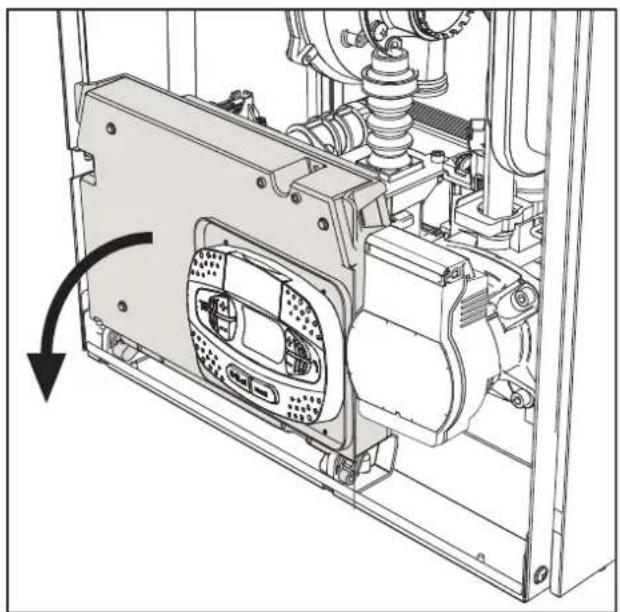
- Turn the Throttle (fig. 32) according to the position indicated in table 7.
- Apply the label, contained in the conversion kit, near the data plate.
- Refit the front panel and turn on the power to the boiler.
-
Modify the parameter for the type of gas:
-
Put the boiler in standby mode and press the Reset button (detail 6 - fig. 1) for 10 seconds.
- The display shows 100 and the text "co" flashing; press the "Heating +" button (detail 4 - fig. 1) to set and view 120. Then press the "DHW+" button (detail 2 - fig. 1) to set 123.
- Press the Reset button once (detail 6 - fig. 1).
- The display shows tS flashing; press the "Heating +" button once (detail 4 - fig. 1).
• The display shows Sc flashing; press the Reset button once (detail 6 - fig. 1).
• The display shows Sc alternating with 01 flashing; - Press the DHW buttons to set the parameter as per table 7.
- press the "Heating +" button (detail 4 - fig. 1).
• The display shows Sc alternating with 02 flashing; - Press the Reset button (detail 6 - fig. 1) for 10 seconds; the boiler will return to standby.
The fan will be activated for about 20 seconds.
- Turn on the gas.
7. MAKE SURE THE FRONT CASING IS CLOSED AND THE INTAKE/FUME EXHAUST DUCTS ARE COMPLETELY ASSEMBLED
Put the boiler in heating or DHW mode for at least 2 minutes. During this period the boiler performs a calibration and the flame symbol flashes on the display. The end of calibration is indicated by the flame symbol steady on the display.
Check the combustion values (see following paragraph).
Table. 7- THROTTLE position and parameter setting
| Gas family | Gas type | Throttle position | Parameter setting |
| 2^nd | G20 1 n | A | |
| 3^rd | G31 2 L | P |
natural_image
Technical diagram of a mechanical assembly with a directional arrow indicating motion (no text or symbols present)fig. 31

fig. 32
Checking the combustion values
MAKE SURE THE FRONT CASING IS CLOSED AND THE FLUE SYSTEM IS CORRECTLY ASSEMBLED & INSTALLED TO THE CURRENT REGULATIONS.
- Put the boiler in heating or DHW mode for at least 2 minutes. During this period if the flame symbol flashes on the display, it means that the boiler is performing a calibration. Wait until the flame becomes steady (end of calibration).
- Activate the TEST mode (see "TEST mode activation" on page 24).
- With the boiler working at maximum and then minimum output, connect a calibrated electronic combustion analyser, to the flue gas sampling point on the appliance conector, check that the CO2 content in the flue, matches that given in the below table.
| Combustion Values G20 G31 | |||
| A New boiler (first ignition/conversion or electrode replacement) 7.5%-9.9% 9%-11.5% | |||
| B | Boiler with at least 500 hours of operation | 9%+/-0.8 | 10%+/-0.8 |
- If the combustion values do not match, perform the 100% calibration as described in the following paragraph.
- Value A: if the values still do not match, do not activate other calibrations, as the system needs to work longer to be able to self-adapt.
- Value B: if the values still do not match yet, proceed with activation of the parameter SC12 or SC13, depending on the type of adjustment necessary (see "Sc" - Combustion Control Parameters Menu" on page 29)
100% calibration
IMPORTANT: DURING THE AUTOMATIC CALIBRATION PROCESS OF THE CO2 VALUE, THE FRONT CASING OF THE BOILER MUST BE CLOSED AND THE CHIMNEY / FLUE SYSTEM CORRECTLY ASSEMBLED & INSTALLED TO THE CURRENT REGULATIONS.
100% calibration, manual
Calibration procedure.
- Put the boiler (preferably) in heating mode or else in DHW mode. Press the Reset button (detail 6 - fig. 1) for 10 seconds.
- The display shows 100 and the text "Co" flashing; press the "Heating +" button (ref. 4 fig. 1) to set and view 120.
- Then press the "DHW +" button (ref. 2 fig. 1) to set 123.
- Press the Reset button (ref. 6 fig. 1) once.
- The display shows Ts flashing; press the "heating +" button (ref. 4 fig. 1) once.
- The display shows Sc flashing; press the reset button once.
- The display shows Sc alternating with 01 flashing;
- Press the "heating +" button (ref. 4 fig. 1) until displaying Sc alternately with 15 flashing;
- Press the "DHW +" button and the display shows "00";
- Press the "DHW +" button and the display shows "01";
- Press the "heating +" button (ref. 4 fig. 1) and the 100% calibration mode will activate, displaying the message "CA" and "LI" alternating.
• After calibration, the display will show Sc alternating with 15 flashing. - Press Reset (ref. 6 fig. 1) for 10 seconds to exit the Sc menu.
100% calibration, automatic
Automatic calibration can occur under certain circumstances in the absence of a DHW or heating demand and is indicated by the flashing flame symbol on the display.
Loading parameters with "BCC KEY"
The "BCC KEY" device allows the updating of combustion parameters for boiler type.
It is used in case of replacement of the PCB of some boiler models.
To use the "BCC KEY", refer to the instructions contained in the kit code 3980H730.
TEST mode activation
Perform a heating or DHW demand.
Press the heating buttons (detail 3 and 4 - fig. 1) together for 5 seconds to activate TEST mode. The boiler lights at Ignition rate & the ramps up to maximum heating power set, as described in the following section.
The heating and DHW symbols (fig. 33) flash on the display; the heating power will appear alongside.

fig. 33- TEST mode (heating power = 100%)
Press the heating buttons (details 3 and 4 - fig. 1) to increase or decrease the power (Minimum=0%, Maximum=100%).
By pressing the DHW “-” button (detail 1 - fig. 1), boiler output is immediately adjusted to minimum (0%).
Wait about 1 minute for stabilisation.
By pressing the DHW “+” button (detail 2 - fig. 1), boiler output is immediately adjusted to maximum (100%).
If the TEST mode is activated and enough hot water is drawn to activate the DHW mode, the boiler remains in TEST mode but the 3-way valve goes to DHW.
To deactivate the TEST mode, press the heating buttons simultaneously (details 3 and 4 - fig. 1) for 5 seconds.
The TEST mode is automatically disabled after 15 minutes or upon turning off the hot water tap (if enough hot water is drawn to activate DHW mode).
Heating power adjustment
To adjust the heating power, switch the boiler to TEST mode (see sec. 3.1). Press the heating buttons detail 3 - fig. 1 to increase or decrease the power (min. = 00 - max. = 100). Press the reset button within 5 seconds and the maximum output will be saved. Exit TEST mode (see sec. 3.1).
Service menu
ONLY FERROLI TRAINED PERSONNEL CAN ACCESS THE SERVICE MENU AND MODIFY PARAMETERS.
The PCB Service Menu is accessed by pressing the Reset button for 10 seconds.
The display will show: "100" and the message "co" flashing.
Then set "103" with the DHW buttons, with the heating buttons set "123" and confirm by pressing the Reset button.
Five submenus are available: press the Heating buttons to select increasing or decreasing order, "tS", "sC", "In", "Hi" or "rE".
To enter the selected menu, press the reset button once.
“tS” - Engineers Parameters Menu
Press the Heating buttons to scroll the list of parameters in increasing or decreasing order. Press the DHW buttons to view or modify the value of a parameter: the change will be automatically saved.
| Contents | Description Range Default | ||
| b01 | Boiler type selection 1=RRP, 2=RRH, 3=RRT, 4=RRK | 3=RRT | |
| b02 | Exchangeer type 1÷4 1 | ||
| b03 | Absolute Maximum Heating Power (b02=1) | 0-100% (Do not modify the value) | 83% |
| Absolute Maximum Heating Power (b02=2) | 0-100% (Do not modify the value) | 85% | |
| Absolute Maximum Heating Power (b02=3) | 0-100% (Do not modify the value) | 85% | |
| Absolute Maximum Heating Power (b02=4) | 0-100% (Do not modify the value) | 90% | |
| b04 | System water pressure protection selection | 0=Pressure switch, 1=Pressure sensor | 0=Pressure switch |
| b05 | DHW mode | 0 = Enabled, 1 = Disabled | 0 = Enabled |
| b06 | Variable input contact operation selection (b01=1) | 0=Flowmeter off, 1=System thermostat, 2=Second room thermostat, 3=Warning/Notification, 4=Safety thermostat | 2=Second room therm. |
| Variable input contact operation selection (b01=2) | 0=Continuous Comfort, 1=System thermostat, 2=Second room thermostat, 3=Warning/Notification, 4=Safety thermostat | 2=Second room therm. | |
| Variable input contact operation selection (b01=3) | 0=Flowmeter off, 1=System thermostat, 2=Second room thermostat, 3=Warning/Notification, 4=Safety thermostat | 2=Second room therm. | |
| Variable input contact operation selection (b01=4) | 0=Continuous Comfort, 1=System thermostat, 2=Second room thermostat, 3=Warning/Notification, 4=Safety thermostat | 2=Second room therm. | |
| b07 | Relay PCB LC32 operation selection (b01=1) | 0=External gas valve, 1=Alarm, 2=System loading solenoid valve, 3=solar 3-way valve, 4=Second heating pump, 5=Alarm2, 6=Burner On, 7=Frost protection active. | 0=External gas valve |
| Relay PCB LC32 operation selection (b01=2) | 0=External gas valve, 1=Alarm, 2=System loading solenoid valve, 3=Legionella pump, 4=Second heating pump, 5=Alarm2, 6=Burner On, 7=Frost protection active. | 0=External gas valve | |
| Relay PCB LC32 operation selection (b01=3) | 0=External gas valve, 1=Alarm, 2=System loading solenoid valve, 3=solar 3-way valve, 4=Second heating pump, 5=Alarm2, 6=Burner On, 7=Frost protection active. | 0=External gas valve | |
| Relay PCB LC32 operation selection (b01=4) | 0=External gas valve, 1=Alarm, 2=System loading solenoid valve, 3=solar 3-way valve, 4=Second heating pump, 5=Alarm2, 6=Burner On, 7=Frost protection active. | 0=External gas valve | |
| b08 | Hours without DHW demand (b01=1) | 0-24 hours (time for temporary deactivation of comfort mode without demand) | 24 hours |
| No effect on adjustment (b01=2) | 0-24 hours (time for temporary deactivation of comfort mode without demand) | 24 hours | |
| Hours without DHW drawn (b01=3) | 0-24 hours (time for temporary deactivation of comfort mode without demand) | 24 hours | |
| No effect on adjustment (b01=4) | 0-24 hours (time for temporary deactivation of comfort mode without demand) | 24 hours | |
| Contents | Description | Range | Default |
| b09 Fault 20 status selection | 0=Deactivated, 1=Enabled (Only for versions with pressure sensor) | 0=Deactivated | |
| b10 | Comfort burner on time (b01=1) 0-40 seconds 15 seconds | ||
| Not implemented (b01=2) -- -- | |||
| Not implemented (b01=3) -- -- | |||
| Not implemented (b01=4) -- -- | |||
| b11 | Flowmeter timing (b01=1) 0=Deactivated, 1-10=seconds 0=Deactivated | ||
| Hot water tank preparation mode (b01=2) 0=Fixed primary, 1=Linked to setpoint, 2=Ramp 0=Fixed primary | |||
| Flowmeter timing (b01=3) 0=Deactivated, 1-10=seconds 0=Deactivated | |||
| Hot water tank preparation mode (b01=4) 0=Fixed primary, 1=Linked to setpoint, 2=Ramp 0=Fixed primary | |||
| b12 | Modulation delta (b01=1) 0-30°C/10 0°C/10 | ||
| Priority override - Activation (b01=2) 0-255 minutes 30 minutes | |||
| Modulation delta (b01=3) 0-30°C/10 0°C/10 | |||
| Priority override - Activation (b01=4) 0-255 minutes 30 minutes | |||
| b13 | Not implemented (b01=1) -- -- | ||
| Priority override - Deactivation (b01=2) 0-255 minutes 15 minutes | |||
| Not implemented (b01=3) -- -- | |||
| Priority override - Deactivation (b01=4) 0-255 minutes 15 minutes | |||
| b14 Pump antiblock operation time 0-20 seconds 5 seconds | |||
| b15 | Flowmeter type selection (b01=1) | 0=Flow. (450 imp/l), 1=Flow. (700 imp/l), 2= Flow. (190 imp/l) | 2= Flowmeter (190 imp/l) |
| No effect on adjustment (b01=2) | 0=Flow. (450 imp/l), 1=Flow. (700 imp/l), 2= Flow. (190 imp/l) | 2= Flowmeter (190 imp/l) | |
| Flowmeter type selection (b01=3) | 0=Flow. (450 imp/l), 1=Flow. (700 imp/l), 2= Flow. (190 imp/l) | 2= Flowmeter (190 imp/l) | |
| No effect on adjustment (b01=4) | 0=Flow. (450 imp/l), 1=Flow. (700 imp/l), 2= Flow. (190 imp/l) | 2= Flowmeter (190 imp/l) | |
| b16 Fan frequency in standby mode 0-100% | 0% | ||
| b17 | Summer/Winter symbol | 0 = Disabled, 1 = Enabled | 0 = Disabled |
| b18 | DHW mode activation flow rate (b01=1) | 0-100L/min/10 | 25 |
| No effect on adjustment (b01=2) | 0-100L/min/10 | 25 | |
| DHW mode activation flow rate (b01=3) | 0-100L/min/10 | 25 | |
| No effect on adjustment (b01=4) | 0-100L/min/10 | 25 | |
| b19 | DHW mode deactivation flow rate (b01=1) | 0-100L/min/10 | 20 |
| No effect on adjustment (b01=2) | 0-100L/min/10 | 20 | |
| DHW mode deactivation flow rate (b01=3) | 0-100L/min/10 | 20 | |
| No effect on adjustment (b01=4) | 0-100L/min/10 | 20 | |
| b20 | Flue material selection | 0=Standard, 1=PVC, 2=CPVC | 0=Standard |
| b21 | PVC flue maximum temperature | 60-110°C | 88°C |
| b22 | CPVC flue maximum temperature | 60-110°C | 93°C |
| b23 | Standard flue shutdown maximum temperature | 60-110°C | 100°C |
| b24 | PVC flue shutdown maximum temperature | 60-110°C | 93°C |
| b25 | CPVC flue shutdown maximum temperature | 60-110°C | 98°C |
| b26 | Flow temperature limit in automatic calibration | 25°C + 55°C | 25°C |
| b27 | Maximum temperature during calibration in DHW mode | 75°C + 95°C | 75°C |
| b28 | Flowmeter sensitivity factor | 0 ÷ 60 (0 = disabled) | 20 |
| b29 Restoring Factory Values | Change the value from 0 to 10 by pressing the “DHW+” button. Confirm by pressing the “heating+” button. | - | |
| P30 | Heating ramp rate | 1-20°C/minute | 4°C/minute |
| P31 | Virtual setpoint min. temperature (b01=1) | 0=Deactivated, 1-80°C | 0=Deactivated |
| Virtual setpoint min. temperature (b01=2) | 0=Deactivated, 1-80°C | 0=Deactivated | |
| Virtual setpoint min. temperature (b01=3) | 0=Deactivated, 1-80°C | 0=Deactivated | |
| Virtual setpoint min. temperature (b01=4) | 0=Deactivated, 1-80°C | 0=Deactivated | |
| P32 | Heating standby time | 0-10 minutes | 4 minutes |
| P33 | Heating Post-Circulation | 0-255 minutes | 15 minutes |
| P34 Pump operation 0-3 = Operation strategy 2 | |||
| P35 Modulating pump min. speed 30-100% 30% | |||
| P36 Modulating pump start speed 90-100% 90% | |||
| P37 Modulating pump max. speed 90-100% 100% | |||
| P38 | Pump deactivation temperature during Post-Circulation (b01=1) | 0-100°C 50°C | |
| Pump deactivation temperature during Post-Circulation (b01=2) | 0-100°C 55°C | ||
| Pump deactivation temperature during Post-Circulation (b01=3) | 0-100°C 55°C | ||
| Pump deactivation temperature during Post-Circulation (b01=4) | 0-100°C 55°C | ||
| P39 | Pump activation hysteresis temperature during Post-Circulation (b01=1) | 0-100°C 10°C | |
| Pump activation hysteresis temperature during Post-Circulation (b01=2) | 0-100°C 25°C | ||
| Pump activation hysteresis temperature during Post-Circulation (b01=3) | 0-100°C 25°C | ||
| Pump activation hysteresis temperature during Post-Circulation (b01=4) | 0-100°C 25°C | ||
| P40 Heating user max. setpoint 20-90°C 80°C | |||
| P41 Max. output in heating 0-100% 80% | |||
| P42 | Burner shutdown in DHW (b01=1) 0=Fixed, 1=Linked to setpoint, 2=Solar 0=Fixed | ||
| Legionella protection (b01=2) | 0-7=Days of activation (1 = Once every 24 hours / 7= Once every 168 hours) | 0=No protection | |
| Burner shutdown in DHW (b01=3) 0=Fixed, 1=Linked to setpoint, 2=Solar 0=Fixed | |||
| Legionella protection (b01=4) 0-7=Activation days | 0=No protection | ||
| P43 | Comfort activation temperature (b01=1) | 0-50°C | 40°C |
| Hot water tank hysteresis (b01=2) | 0-60°C | 2°C | |
| Comfort activation temperature (b01=3) | 0-80°C | 40°C | |
| Hot water tank hysteresis (b01=4) | 0-60°C | 2°C | |
| P44 | Not used (b01=1) | Do not modify | 0 |
| Primary setpoint (b01=2) | 70-85°C (Primary circuit temperature adjustment in DHW) | 80°C | |
| Comfort deactivation hysteresis (b01=3) | 0-20°C | 20°C | |
| Primary setpoint (b01=4) | 70-85°C (Primary circuit temperature adjustment in DHW) | 80°C | |
| P45 | DHW standby time (b01=1) | 30-255seconds | 120seconds |
| DHW standby time (b01=2) | 30-255seconds | 120seconds | |
| DHW standby time (b01=3) | 30-255seconds | 120seconds | |
| DHW standby time (b01=4) | 30-255seconds | 120seconds | |
| P46 | DHW user max. setpoint (b01=1) | 40-70°C 55°C | |
| DHW user max. setpoint (b01=2) | 40-70°C 65°C | ||
| DHW user max. setpoint (b01=3) | 40-70°C 55°C | ||
| DHW user max. setpoint (b01=4) | 40-70°C 65°C | ||
| P47 | DHW pump Post-Circulation (b01=1) | 0-255seconds | 3seconds |
| DHW pump Post-Circulation (b01=2) | 0-255seconds | 30seconds | |
| DHW pump Post-Circulation (b01=3) | 0-255seconds | 30seconds | |
| DHW pump Post-Circulation (b01=4) | 0-255seconds | 30seconds | |
| P48 Max. output in DHW 0-100% 100% | |||
| P49 | Comfort1 standby time (b01=1) | 0-100minutes | 20minutes |
| Not implemented (b01=2) | -- | -- | |
| Not implemented (b01=3) | -- | -- | |
| Not implemented (b01=4) | -- | -- | |


| Contents | Description | Range | Default |
| P50 | Comfort2 standby time (b01=1) 0-100minutes 42 minutes | ||
| Not implemented (b01=2) -- -- | |||
| Not implemented (b01=3) -- -- | |||
| Not implemented (b01=4) -- -- | |||
| P51 | Solar deactivation temperature (b01=1) 0-100°C 10°C | ||
| Setpoint deltaT (b01=2) 0-20°C 0°C | |||
| Solar deactivation temperature (b01=3) 0-100°C 10°C | |||
| Setpoint deltaT (b01=4) 0-20°C 0°C | |||
| P52 | Solar ignition temperature (b01=1) 0-100°C 10°C | ||
| DHW ramp rate (b01=2) 1-20°C/minute 5°C/minute | |||
| Solar ignition temperature (b01=3) 0-100°C 10°C | |||
| DHW ramp rate (b01=4) 1-20°C/minute 5°C/minute | |||
| P53 | Solar standby time (b01=1) 0-255 seconds | 10 seconds | |
| No effect on adjustment (b01=2) | 0-255 seconds | 0 seconds | |
| Solar standby time (b01=3) 0-255 seconds | 10 seconds | ||
| No effect on adjustment (b01=4) | 0-255 seconds | 0 seconds | |
| P54 | Heating deltaT temperature adjustment (b01=1) | 0-60°C 18°C | |
| Heating deltaT temperature adjustment (b01=2) | 0-60°C 18°C | ||
| Heating deltaT temperature adjustment (b01=3) | 0-60°C 18°C | ||
| Heating deltaT temperature adjustment (b01=4) | 0-60°C 18°C | ||
| P55 | Primary exchanger protection temperature (b01=1) | 0-150°C 43°C | |
| Primary exchanger protection temperature (b01=2) | 0-150°C 43°C | ||
| Primary exchanger protection temperature (b01=3) | 0-150°C 43°C | ||
| Primary exchanger protection temperature (b01=4) | 0-150°C 43°C | ||
| P56 | System min. pressure value | 0-8bar/10 (Only for boilers with water pressure sensor) | 4 bar/10 |
| P57 | System nominal pressure value | 5-20bar/10 (Only for boilers with water pressure sensor) | 7 bar/10 |
| P58 | Exchanger protection intervention (b01=1) | 0=No F43, 1-15=1-15°C/second 10°C/second | |
| Exchanger protection intervention (b01=2) | 0=No F43, 1-15=1-15°C/second 10°C/second | ||
| Exchanger protection intervention (b01=3) | 0=No F43, 1-15=1-15°C/second 10°C/second | ||
| Exchanger protection intervention (b01=4) | 0=No F43, 1-15=1-15°C/second 10°C/second | ||
| P59 | Heating hysteresis after ignition | 6-30°C | 10°C |
| P60 | Timer for heating hysteresis after ignition | 60-180seconds | 60seconds |
Notes:
- Parameters with more than one description vary their function and/or range in relation to the setting of the parameter given in brackets.
- Parameters with more than one description are reset to the default value if the parameter given in brackets is modified.
- The Maximum Heating Power parameter can also be modified in Test Mode.
Press the Reset button to return to the Service Menu. Press the Reset button for 20 seconds to exit the PCB Service Menu, or exiting occurs automatically after 15 minutes.
"Sc" - Combustion Control Parameters Menu
ONLY FERROLI TRAINER & QUALIFIED PERSONNEL CAN ACCESS THE "SC" MENU TO MODIFY THE RELEVANT PARAMETERS.
Press the Heating buttons to scroll the list of parameters “+” increasing “-” decreasing order. Press the DHW buttons to view or modify the value of a parameter. To save the edited parameter press either the heating“+” or “-” button (details 3 and 4 - fig. 1).
| Contents | Description | Functional description | Range | Default |
| Sc01 Gas type selection | Allows the change of gas type. See “Gas conversion” on page 21 | na / LP na | ||
| Sc02 Ignition gas calibration | Allows the amount of gas to be increased or decreased in the ignition phase (Due to poor ignition). | -9 ÷ 20 0 | ||
| Sc03 Ignition power | Allows the fan speed to be increased or decreased in the ignition phase in case of poor ignition. | -16 ÷ 14 0 | ||
| Sc04 N/A For the UK market. -2 ÷ 13 0 | ||||
| Sc05 | Minimum output calibration | Allows the minimum output to be increased, if necessary. | 0 ÷ 25 | 0 |
| Sc06 | Minimum gas valve calibration | Self-adaptive parameter. DO NOT MODIFY. | ||
| Sc07 | Flame ionisation signal | Displays the actual ionisation current signal. | Read only | |
| Sc08 Current power in DHW mode | Displays the actual output related to maximum power in DHW mode. | Read only | ||
| Sc09 | MAX ionisation value | Displays the maximum ionisation value reached. | Read only | |
| Sc10 Minimum ionisation value during ignition | Displays the minimum ionisation value reached during the ignition phase. | Read only | ||
| Sc11 | Ignition time | Displays the time from fan activation to ionisation. | Read only | |
| Sc12* | Ionisation reduction value (BASE) | Allows the adjustment of CO2 at the same time as maximum and minimum power, translating the entire value curve. | -5 ÷ 10 0 | |
| Sc13** | Ionisation reduction value (min.) | Allows the adjustment of CO2 at minimum power. | -5 ÷ 10 0 | |
| Sc14 | Internal error K1 | Displays the SCOT system error code. | Read only | |
| Sc15 100% CALIBRATION | Allows 100% Calibration (see “100% calibration” on page 23) when replacing some components (see “Replacement of major components & testing” on page 34) | 0 - CAL | 0 | |
| Sc16 DO NOT MODIFY. | ||||
PARAMETERS "SC12" AND "SC13" MUST ONLY BE MODIFIED, IF STRICTLY NECESSARY, BY QUALIFIED PERSONNEL AND ONLY WHEN THE CO₂ VALUES ARE OUTSIDE THE RANGE INDICATED IN "- Technical data table" on page 47. CARRY OUT THE PROCEDURE AFTER AT LEAST 500 HOURS OF BOILER OPERATION.
* SC12 regulates the CO2 at the same time at maximum and minimum power. By increasing the parameter value the CO2 reduces; by decreasing the parameter value the CO2 increases.
** SC13 regulates the CO2 at minimum power. By increasing the parameter value the CO2 reduces; by decreasing the parameter value the CO2 increases.


Procedure for modifying parameter SC12:
• Create a demand for heating or DHW and then press the reset button (ref. 6 fig. 1) for 10 seconds.
• The display shows 100 and the text "Co" flashing; press the "Heating +" button (ref. 4 fig. 1) until 120 is displayed.
- Then press the "DHW+" button (ref. 2 fig. 1) until the access code 123 is displayed.
- Press the reset button (ref. 6 fig. 1) once.
• The display shows Ts flashing; press the "heating +" button (ref. 4 fig. 1) once.
- The display shows Sc flashing; press the reset button once.
• The display shows Sc alternating with 01 flashing;
- Press the "heating +" button (ref. 4 fig. 1) until displaying Sc alternately with 15 flashing;
- Press the "DHW +" button and the display shows "00";
- Press the "DHW +" button until the display shows "02";
- Press the "heating +" button (ref. 4 fig. 1) to confirm and the 100% calibration mode will activate displaying the message "CA" and "LI" alternating.
- after just over a minute the calibration mode will end and the display will show "C" alternating with "12" with the continuous flame symbol.
- press the "DHW +" or "DHW -" button to set the "SC12" parameter value to the value that allows CO₂ optimisation.
- press the "heating +" button to confirm the value. The display shows "Sc" alternating with "15".
- Press the Reset button to return to the Service Menu. Press the Reset button for 10 seconds to exit the PCB Service Menu, or exiting occurs automatically after 15 minutes
- put the boiler in TEST mode and check the CO _2 value at maximum and minimum power with a calibrated electronic flue gas analyser.
Procedure for modifying parameters SC12 and SC13:
• Create a demand for heating or DHW and then press the Reset button (ref. 6 fig. 1) for 10 seconds.
- The display shows 100 and the text "Co" flashing; press the "Heating +" button (ref. 4 fig. 1) until 120 is displayed.
- Then press the "DHW +" button (ref. 2 fig. 1) until the access code 123 is displayed.
- Press the Reset button (ref. 6 fig. 1) once.
• The display shows Ts flashing; press the "heating +" button (ref. 4 fig. 1) once.
• The display shows Sc flashing; press the reset button once.
• The display shows Sc alternating with 01 flashing;
- Press the "heating +" button (ref. 4 fig. 1) until displaying Sc alternately with 15 flashing;
- Press the "DHW +" button and the display shows "00";
- Press the "DHW +" button until the display shows "03";
- Press the "heating +" button (ref. 4 fig. 1) to confirm and the 100% calibration mode will activate displaying the message "CA" and "LI" alternating.
- after just over a minute the calibration mode will end and the display will show "C" alternating with "12" with the continuous flame symbol.
- press the "DHW +" or "DHW -" button to set the "SC12" parameter value to the value that allows CO₂ optimisation.
- press the "heating +" button to confirm the value. The display shows "CA" and "LI" alternately to indicate that a further calibration is being performed.
- after just over a minute the calibration mode will end and the display will show "C" alternating with "15" with the continuous flame symbol.
- press the "DHW +" or "DHW -" button to set the "SC13" parameter value to the value that allows CO₂ optimisation.
- press the "heating +" button to confirm the value. The display "SC" appears alternately to "15".
- Press the Reset button to return to the Service Menu. Press the Reset button for 10 seconds to exit the PCB Service Menu, or exiting occurs automatically after 15 minutes
- put the boiler in TEST mode and check the CO _2 value at maximum and minimum power with a calibrated electronic flue gas analyser.
"In" - Information Menu
12 views of information are available.
Press the Heating buttons to scroll the list of information in increasing or decreasing order. Press the DHW buttons to display the value.
| Contents Description Range | ||
| t01 NTC Heating sensor (°C) 0÷125 °C | ||
| t02 NTC Return sensor (°C) 0÷125 °C | ||
| t03 NTC DHW sensor (°C) 0÷125 °C | ||
| t04 NTC (optional) External sensor (°C) +70 ÷ -30°C (negative values flash) | ||
| t05 NTC Flue gas sensor (°C) 0÷125 °C | ||
| F06 Actual fan rpm 00÷120 x100RPM | ||
| L07 Actual burner power (%) 00%=Min., 100%=Max. | ||
| F08 Actual DHW flow rate (l/min/10) 00÷99 l/min/10 | ||
| P09 | Actual system water pressure (bar/10) | 00=With Pressure switch open,14=With Pressure switch open, 00-99 bar/10 with Pressure transducer |
| P10 | Actual modulating pump speed (%) | 00÷100% |
| P11 Burner operating hours | 00÷99 x | 100 hours |
| F12 Flame status | 00÷255 | μA |
Notes:
- In case of damaged sensor, the PCB displays hyphens (--).
Press the Reset button to return to the Service Menu. Press the Reset button for 10 seconds to exit the PCB Service Menu, or exiting occurs automatically after 15 minutes.
"Hi" - History Menu
The PCB can store the last 8 fault codes: the History data item H1 represents the most recent fault that occurred, whereas the History data item H08 represents the least recent.
(The fault codes can also be viewed in the relevant menu of the optional OpenTherm Remote Timer Control).
Press the Heating (+) button to scroll through the list of faults in increasing order or (-) button to view in decreasing order. Press the DHW (+) button to display the fault value.
Press the Reset button to return to the Service Menu. Press the Reset button for 10 seconds to exit the PCB Service Menu, or exiting occurs automatically after 15 minutes.
"rE" - History Reset
Press the Winter/Summer/Off-On button for 3 seconds to delete all stored faults in the History Menu: NOTE the PCB automatically exits the Service Menu, in order to confirm the operation.
Press the Reset button for 10 seconds to exit the PCB Service Menu, or exiting occurs automatically after 15 minutes.
3.2 Commissioning
Before lighting the boiler
- Check the tightness of the gas system & rectify any leaks before continuing.
- Check the correct expansion vessel pressure (1.0 bar with no system pressure).
- Fill the hydraulic system and make sure that all air contained in the boiler and the system has been vented.
- Make sure there are no water leaks in the system, DHW circuits, connections or boiler.
- Make sure there are no flammable liquids or materials near the boiler.
- Check correct connection of the electrical supply and efficiency of the Earth system.
- Make sure the gas valve is adjusted for the gas to be used (see "- THROTTLE position and parameter setting" on page 22 and fig. 32 on page 22 of cap. 3.1 "Adjustments").
- Fill the trap (see cap. 2.7 "Condensate drain connection").

FOR SAFETY REASONS THE AFOREMENTIONED SHOULD BE OBSERVED TO PREVENT AN ESCAPE OF GAS OR A BUILD-UP OF FUMES WITHIN THE BUILDING. THE POWER SUPPLY MUST BE ISOLATED BEFORE WORKING ON ANY COMPONENTS WITHIN THE BOILER TO PREVENT ANY RISK OF ELECTRIC SHOCK.
First boiler ignition
- Ensure there is no demand for hot water or Heating.
- Ensure there is gas and electrical power to the boiler; the display will show the software version number and then Fh and FH air venting cycle (see cap. 1.3 "Connection to the power supply, switching on and off" on page 5).
- At the end of the FH cycle, the winter mode screen (fig. 8) will appear on the display; Adjust the heating & DHW outlet temperature settings as required (fig. 12 and fig. 13).
- Top change the Gas type (G20 - G31), check if the relevant parameter is suitable for the type of gas present in the supply system ("Sc" - Combustion Control Parameters Menu" on page 29 and cap. 3.1 "Adjustments" on page 21).
- Set the boiler to DHW or heating mode (see cap. 1.3 "Connection to the power supply, switching on and off" on page 5).
- In Heating mode, create a demand: the display shows the "Radiator symbol" and the actual heating system temperature; when the flashing flame symbol appears, the burner is lit and the system is performing the calibration. Wait for the end of calibration, indicated by the stable flame symbol.
- DHW with hot water demand: the display shows the "Tap symbol" and the actual DHW temperature; when the flashing flame symbol appears, the burner is lit and the system is performing the calibration; wait for the end of the calibration, indicated by the stable flame symbol.
- Carry out the fuel check as described in section 3.1. "Checking the combustion values" on page 22.
- Check that the gas inlet working pressure ahead of the unit complies with the technical data table or as per the regulations in force at that time.
3.3 Maintenance
IMPORTANT

ALL MAINTENANCE WORK AND REPLACEMENT OF PARTS MUST BE CARRIED OUT BY SUITABLY QUALIFIED PERSONNEL WHO ARE GAS SAFE REGISTERED IN THE RELEVANT CATAGORY.
Before carrying out any operation inside the boiler, disconnect the power supply and close the gas isolation valve upstream of the boiler.
Opening the front panel

Some internal components of the boiler can reach temperatures high enough to cause severe burns or scalding. Before carrying out any operation, wait for these components to cool or wear suitable hand protection.
To open the boiler casing:
- Partially undo the screws A (see fig. 34).
- Pull the panel B towards you and lift it from the upper fastenings.
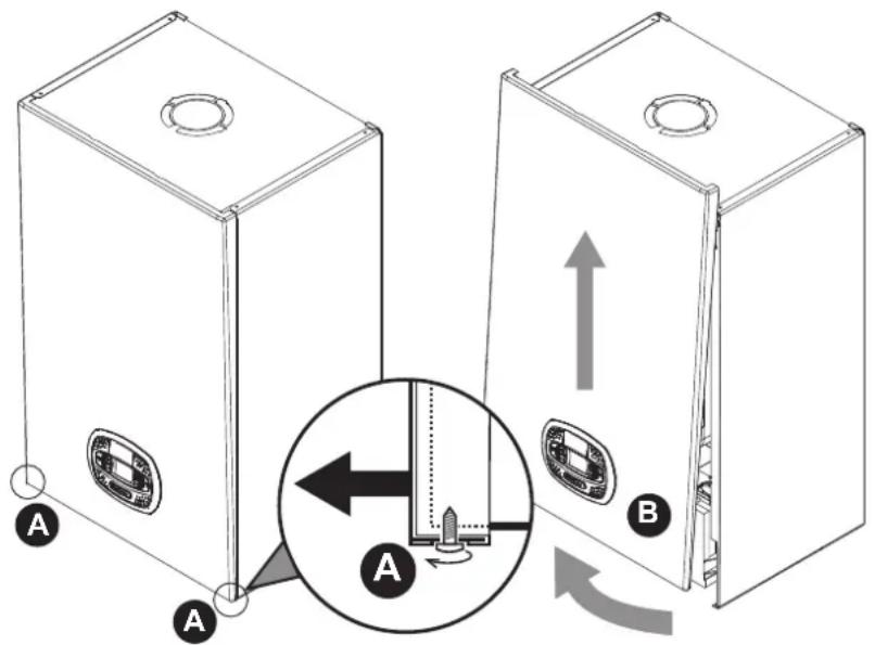
fig. 34- Front panel opening

This boiler has a room sealed casing. After any operation involving opening the boiler, You must ensure that the front panel is correctly located, sealed & the screws tightened.
Proceed in reverse order to refit the front panel. Make sure it is located on the upper fastening and is correctly positioned at the sides. When tightened, the head of screw "A" must sit in the rebate (see fig. 35).

natural_image
Pure technical diagram showing a structural component with no text, numbers, or symbols
fig. 35 - Correct position of front panel
Annual Boiler Service
To ensure the safe operation of the unit over time, a qualified Gas Safe registered engineer must carry out a yearly inspection, and complete the following checks:
- The control and safety devices (gas valve, flow meter, thermostats, etc.) must operate correctly.
• The flue exhaust duct must be sealed.
• The boiler casing or chamber must be room sealed.
• The Flue terminal and ducts must be free of obstructions, leaks & located correctly to BS5440. - The burner and exchanger must be clean and free of deposits. Use suitable soft brushes for cleaning. Never use chemical products. (Wash down through the exchanger & out through the condense line with clean warm water).
- The electrode must be correctly positioned and free of scale.
The electrode can be cleaned of encrustation's only with a non-metallic brush, and must NOT be sanded.
• The gas and water systems must be tight.
• The water pressure in the system when cold must be approx. 1.5 bar; otherwise bring it to that value.
• The circulating pump must not be blocked.
- The expansion vessel must be charged to 1.0 bar with no system pressure.
- The gas flow and Inlet working pressure must match that given in the respective tables.
- The condense pipework must be solvent weld, sealed & free of debris or blockages.
• The condense trap must be full of water.
- Check the quality of the water in the heating system via an "alkalinity test" (checking the inhibitor concentration).
- Check the condition of the insulation within the exchanger & around the burner (Replace if cracked or damaged).
- Check the flexible gas connection between the valve and Venturi.
- Replace the burner gasket if damaged or over 5 years.
- Finally, always check the combustion parameters (see "checking the combustion values").
Replacement of major components & testing
After replacing the gas valve, burner, electrode or circuit board, it is necessary to carry out the 100% calibration (see "100% calibration" on page 23). Then follow the instructions in par. "Checking the combustion values" on page 22.
Gas valve
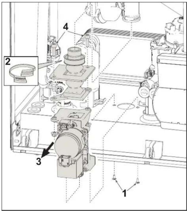
fig. 36- Gas valve replacement
- Disconnect the power supply and turn off the isolation valve upstream of the gas valve.
- Disconnect the two electrical connectors to the gas valve
- Disconnect the gas supply pipe to the gas valve
- Undo the screws "1"
- Remove the clamp "2"
- Remove the gas valve "3"
- Then undo the screws "4"
- Fit the new valve, carrying out the above steps in reverse order.
Refer to the instruction sheet included in the kit when replacing the gas Injector cartridge..
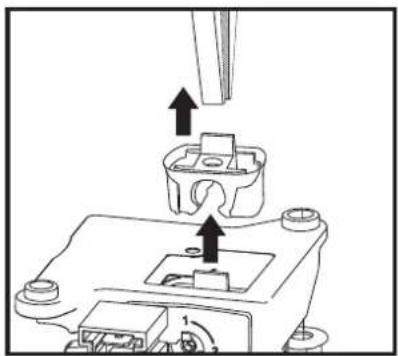
natural_image
Technical line drawing of a mechanical assembly with arrows indicating force or movement (no text or symbols)fig. 37- Gas Injector cartridge replacement
Plate heat exchanger

Before carrying out the following instructions it is advisable to protect the area and the boiler's PCB housing against accidental water spillage.


natural_image
Technical line drawing of an internal mechanical assembly with no visible text or symbolsfig. 38- Plate to plate heat exchanger replacement/maintenance
• Isolate the power supply to the boiler.
- Isolate the boiler by closing the DHW inlet, Flow & Return isolation valves.
- Open a hot tap (preferably below the height of the boiler) to drain the domestic hot water.
- Remove the lower security screw & pivot the Fascia housing down "1"
- Drain the water in the boiler through the drain tap (see *** System draining on page 8 *** )
- Undo the screws "2"
- Move the plate heat exchanger back and slide it slightly to the left "3"
- Remove the plate heat exchanger as shown in the figure "4"
- Note: To gain more access you can easily remove the flexible connection on the top of the condense trap
- When refitting the plate heat exchanger, make sure the arrows (indicating: HEATING) are pointing downwards.
Circulating pump

Before carrying out the following instructions it is advisable to protect the area and the boiler's PCB housing against accidental water spillage.


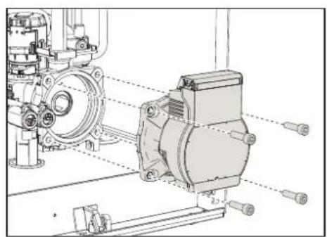
natural_image
Technical line drawing of a mechanical assembly with no visible text or symbolsfig. 39 fig. 40 fig. 41
- Isolate the power supply and close the Gas isolation valve to the boiler.
- Pull up the security tab "1" of fig. 39 then remove both electrical connections to the pump "2".
- Close the flow & return Isolation valves, & drain the water in the boiler "3" of fig. 40 " (see "System draining" on page 8).
- Unscrew (4 x 5mm Allen key bolts) and remove the circulating pump motor assembly of fig. 41.
- Replace in reverse order, refill the boiler, re-establish the power supply & test
Replacing the main exchanger

Before carrying out the following instructions it is advisable to protect the area and the boiler's PCB housing against accidental water spillage.

fig. 42- Main exchanger
- Isolate the power supply and close the Gas isolation valve to the boiler.
- Disconnect the lead to the flue temperature sensor, Remove the sensor & save (Please fit this into the replacement exchanger housing in readiness).
- Disconnect the fan power lead.
- Disconnect the white lead to the ignition electrode from the Printed Circuit board, & release the earth tag.
- Remove the ignition electrode (2 x T15 Torx screws) Take care not to damage the gasket, replace if damaged.
- Close ALL the isolation valves to the boiler & drain both the heating & hot water circuits down.
- Remove the appliance flue connection (concentric or adaptor for separate ducts)
- Remove the fan assembly (2 x 4mm Allen key bolts) Take care not to damage the cork gasket, replace if damaged.
- Remove the 4 x spring clips "1" on the two pipes "2" to the exchanger, pump and hydraulic unit & lift away.
- Remove the flexible connection from the top of the condense trap "4"
- Remove the burner assembly (fig. 43) Remove the fan diaphragm & install into the new exchanger.
- Release the clamp to the flexible gas connection (Save & re-use later)
- Remove the 2 top screws "5" securing the exchanger to the frame (fig. 42)
- Loosen the 2 bottom screws "5" securing the exchanger to the frame (fig. 42)
- Remove the exchanger from the boiler casing (take care not to spill any remaining water) "6"
- Slot the new exchanger onto the bottom screws "5"
- Refit the Ignition electrode, Burner assembly, Fan, Condense connection, Flexible Gas connection & any removed electrical connections
- Fit the supplied 'O' rings to the flow & return pipes, lubricate with silicone grease (not supplied) then re-fit the pipes & spring clips.
- Open all isolation valves to re-fill the boiler, purge out the air, re-establish the power & test (Please follow GSIUR 26/9)
Disassembling the burner and cleaning the exchanger
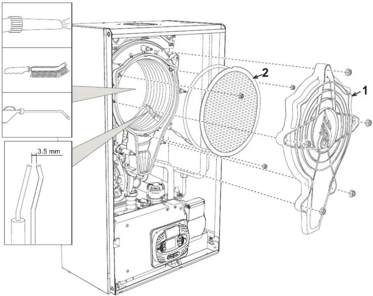
fig. 43
- Isolate the power supply and close the Gas isolation valve to the boiler.
- Undo the 5 x 10mm flange nuts securing the exchanger cover "1".
- Undo the 3 x 10mm nuts securing the burner & remove (To clean use a soft brush & vacuum).
- Check the correct distance of the electrode (clean if necessary but do not sand).
• To clean the exchanger, it is advisable to remove the electrode (see fig. 46). - Clean the inside of the exchanger with a soft brush & wash through with clean warm water, then clean out the condense sediment bowl. (See the accessories indicated in fig. 43)
- Replace in reverse order & carry out GSIRU 26/9 tests.
Exchanger insulation replacement
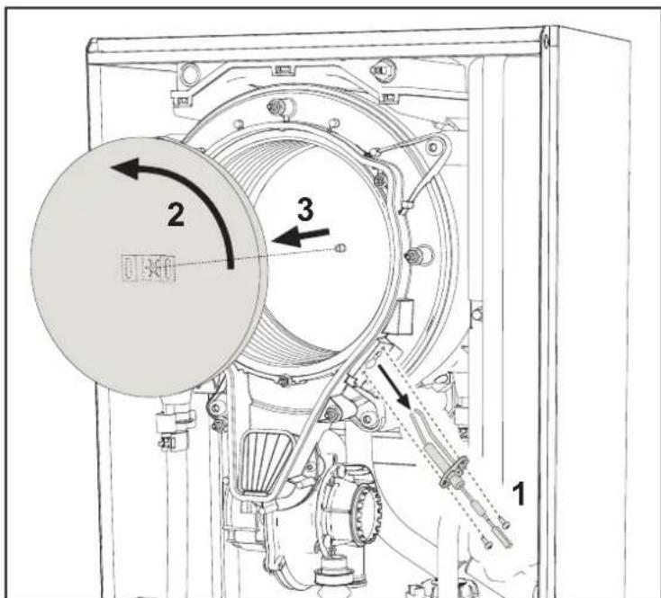
- Isolate the power supply and close the Gas isolation valve to the boiler.
- Remove the cover of the heat exchanger and the burner (see fig. 43 Removing the burner and cleaning the heat exchanger).
- Remove the ignition electrode (2 x T15 Torx screws) Take care not to damage the gasket, replace if damaged. "1".
- Rotate the insulating disc "2" and remove it, (Dispose of the damaged insulation pad safely this cannot be reused)
• Install the new insulation pad to the heat exchanger ensuring its correctly secured to the tab the reassemble the boiler.
Fan

fig. 44
- Isolate the power supply and close the Gas isolation valve to the boiler.
- Remove the electrical connection to the fan.
- Remove the clamp "1" and undo & remove the screws "2".
- Remove the fan "3" & replace the gasket if damaged.
- When installing / replacing a fan a combustion calibration must be carried out (see "100% calibration" on page 23).
Replacing the circuit board

fig. 45
- Isolate the power supply and close the Gas isolation valve to the boiler.
- After lowering the PCB housing, lift the cover by pulling the tabs open "2".
- Remove all the electrical connections
- Remove the PCB by pulling the tabs open on the side & lifting it out "4".
- Insert the new PCB and reconnect the electrical connections.
To update the circuit board data, use the "KEY" device, following the instructions attached to the kit.
Electrode replacement or maintenance
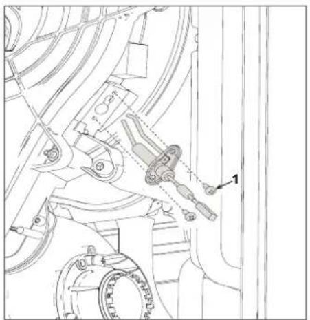
fig. 46
- Isolate the power supply and close the Gas isolation valve to the boiler.
- Disconnect the white ignition lead from the PCB housing and remove the electrode by undoing the screws "1".
- Remove the exchanger cover and remove the burner (see fig. 43).
- Clean the electrode (see fig. 43).
• Refit the clean or new electrode and secure it with the 2 x screws "1" (ensure the gasket is replaced or not damaged).
• After securing in place, carefully check the distance between the electrodes (see fig. 43). - Refit and secure the burner (see fig. 43) (ensure the burner insulation is not damaged otherwise it must be replaced).
• Refit and secure the burner cover (see fig. 43) (ensure the burner cover seal is not damaged & less than 5 years old). - When installing / replacing the burner a combustion calibration must be carried out (See section 3 calibration procedure).
Removing the diverter valve motor head

Before carrying out the following instructions it is advisable to protect the area and the boiler's PCB housing against accidental water spillage.
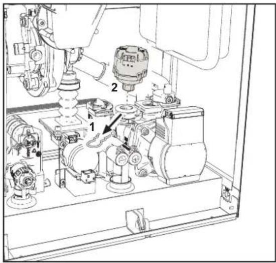
fig. 47
- Isolate the power supply and close the Gas isolation valve to the boiler.
- Remove the diverter valve electrical connection.
- Remove the spring clip "1" and remove the diverter valve "2".
- Replace in reverse order.
Replacing the Low water pressure switch

Before carrying out the following instructions it is advisable to protect the area and the boiler's PCB housing against accidental water spillage.
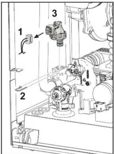
fig. 48
- Isolate the power supply and close the Gas isolation valve to the boiler.
- Turn off the Flow & Return isolation valves & drain the boiler (see system draining fig. 16).
- Remove the electrical connection "1" and fastening spring clip "2".
- Remove the water pressure switch "3".
- Clean or replace the LWP switch then apply silicone grease to the 'O' ring before replacing.
Cleaning or replacing the flowmeter

Before carrying out the following instructions it is advisable to protect the area and the boiler's PCB housing against accidental water spillage.


1 - Flow-rate limiter
2 - Impeller
3 - Filter
4 - Clip
5 - Flowmeter
fig. 49- Flowmeter
- Isolate the power supply and close the Gas isolation valve to the boiler.
- Remove the diverter valve motor head (see fig. 47).
- Close the cold water inlet isolation valve and open a hot water tap in the property
- Release the retaining clip "4" and remove the flowmeter assembly "5" by pulling upwards.
• The flowmeter components can thus be cleaned or replaced (see fig. 50 and fig. 51).
Wash the filter with clean water.
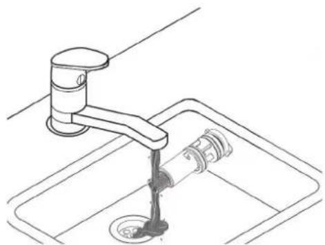
natural_image
Line drawing of a kitchen sink with faucet and drain (no text or symbols)fig. 50
Lubricate the flowmeter 'o ring seals with silicone grease.

natural_image
Technical illustration of a mechanical component with a tool inserted, showing internal structure and no visible text or symbols.fig. 51
3.4 Troubleshooting
Diagnostics
Blank LCD
Make sure that the PCB is powered: using a digital multimeter, check supply voltage is within tolerance (Range 195 - 253 Vac)
In the case of no voltage, check the wiring & check the external 3amp fuse. To access the internal PCB fuse please see fig. 21 and fig. 52 when replacing please ensure it is rated at (3.15AL@230VAC).
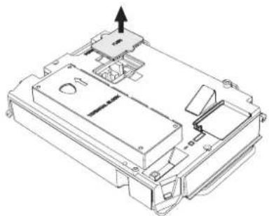
natural_image
Technical line drawing of a mechanical or electronic component with no visible text or symbolsfig. 52- Fuse housing
LCD Fault codes
The display flashes and the relevant fault identification code appears.
There are faults that cause permanent shutdowns or Lock Outs (marked with the letter "A" for Alarm): to restore operation press the reset button once (detail 6 - fig. 1) for less than 1 second or use the RESET on the remote timer control (optional) if installed; if the boiler does not restart, it will be necessary to eliminate the fault (see fault code table).
Other faults cause temporary shutdowns (marked with the letter "F" for Fault) which are automatically reset as soon as the value returns within the boiler's normal working tolerance.
Fault code Table
Table. 8- List of faults
| Fault code | Fault Possible cause Cure | ||
| A01 No burner ignition | No gas | Check for correct gas flow & pressure to the boiler and that the pipework has been purged. | |
| Ignition/detection electrode fault | Check the wiring of the electrode and that it is correctly positioned and free of any deposits; replace / clean the electrode if necessary. | ||
| Faulty gas valve Check the gas valve | and replace it if necessary | ||
| Insufficient gas supply pressure Check the gas supply pressure | |||
| Condense trap or pipes blocked Check the trap and pipes, clean it if necessary | |||
| Air/fume ducts obstructed | Remove the obstruction from the flue, extraction ducts, air inlet and terminals. | ||
| A02 Flame signal present with burner off | Electrode fault | Check the ionisation electrode wiring | |
| Check the condition of the electrode | |||
| Electrode to earth | |||
| Cable to earth | |||
| Check the condenser trap clean it if necessary | |||
| PCB fault Check the PCB | |||
| A05 Fan fault | No 230V power supply | Check the 5-pin connector wiring | |
| Tachometric signal interrupted | |||
| Fan damaged or out of balance Check the fan, clean or replace | |||
| A06 No flame after the ignition phase | Ionisation electrode fault Check the position of the ionisation electrode and replace it if necessary | ||
| Flame unstable Check the burner | |||
| air/flue ducts obstructed | Remove the obstruction from the flue, fume extraction ducts, air inlet and terminals | ||
| Condense trap or pipes blocked Check the trap and pipes clean it if necessary | |||
| F07 - F14 - A07 | High flue gas temperature | The flue gas probe detects an excessive temperature | Check the exchanger |
| Check the flue gas probe | |||
| F08 A08 | Over temperature protection intervention | Heating sensor damaged | Check the correct positioning and operation of the heating sensor and replace it if necessary |
| No water circulation in the system Check the circulating pump | |||
| Air in the system Vent the system | |||
| F09 A09 | Over temperature protection intervention | Return sensor damaged | Check the correct positioning and operation of the return sensor and replace it if necessary |
| No water circulation in the system Check the circulating pump | |||
| Air in the system Vent the system | |||
| F10 A10 | Flow sensor fault | Sensor damaged | Check the wiring or replace the sensor |
| Wiring shorted | |||
| Wiring disconnected | |||
| F11 A11 | Return sensor fault | Sensor damaged | Check the wiring or replace the sensor |
| Wiring shorted | |||
| Wiring disconnected | |||
| F12 | DHW sensor fault | Sensor damaged | Check the wiring or replace the sensor |
| Wiring shorted | |||
| Wiring disconnected | |||
| F13 A13 | Flue probe fault | Probe damaged | Check the wiring or replace the flue probe |
| Wiring shorted | |||
| Wiring disconnected | |||
| Fault code | Fault | Possible cause | Cure |
| A14 | Flue extraction duct safety device intervention | Fault F07 generated 3 times in the last 24 hours | See fault F07 |
| F34 Supply voltage under 170V Electric mains | trouble Check the electrical system | ||
| F37 Incorrect system water pressure | Pressure too low Fill the system | ||
| Water pressure switch damaged blocked or not connected | Check the water pressure switch | ||
| F39 (Optional) External probe fault | Probe damaged or wiring shorted Check the wiring or replace the sensor | ||
| Probe disconnected after activating the outside temperature mode | Reconnect the external probe or disable the outside temperature mode | ||
| F41 | Activation of maximum DELTA T protection | Heating sensor damaged | Check the correct positioning and operation of the heating sensor |
| Return sensor damaged | Check the correct positioning and operation of the return sensor | ||
| No water circulation in the system Check the circulating pump or system blockage | |||
| Air in the system Vent the system | |||
| F42 A42 | Sensor control protection activation | Heating sensor damaged | Check the correct positioning and operation of the heating sensor |
| Return sensor damaged or disconnected | Check the correct positioning and operation of the return sensor | ||
| F43 Exchanger protection intervention. | No system water circulation Check the circulating pump or system blockage | ||
| Air in the system Vent the system | |||
| A23 - A24 - A26 F15 - F20 - F21 F40 - F47 - F50 F51 - F53 | PCB parameter fault Wrong PCB parameter setting | Check the PCB parameter and modify it if necessary | |
| F56 - A56 | Calibration fault | Incorrect parameters | Check parameters and carry out a 100% calibration |
| Electrode damaged or not correctly positioned. | Check the position of the electrode, replace it if necessary. After replacement, repeat the 100% calibration | ||
| Calibration procedure not completed | Poor primary circuit circulation or over heating? | Reset the fault. Open the hot water tap and and wait for the flame to stop flashing (about 2 minutes) | |
| F61 - A61 P | PCB AGC01 fault PCB AGC01 internal error | Check the earth connection, to the electrode & replace the PCB if necessary | |
| A54 - A55 - A63 | PCB AGC01 fault PCB AGC01 internal error | Try disconnecting the power supply to the boiler for 10 seconds and replace the PCB if necessary | |
| F67 BCC Service key connected Load | |||
| F68 - A68 | BCC Service key error | Error loading BCC Service key file | Repeat the loading procedure within 5 minutes from the boiler power supply and replace the BCC Service key if necessary |
| A62 | No communication between PCB and gas valve | PCB not connected | Connect the PCB to the Gas valve |
| Valve damaged Replace valve | Check the wiring or replace the Gas valve | ||
| A64 | Maximum number of consecutive Resets exceeded | Maximum number of consecutive Resets exceeded | Disconnect the power supply to the boiler for 60 seconds and then reinstate the boiler |
| F66 Firmware not loaded successfully Reload | the firmware or replace the PCB | ||
4. Technical data and characteristics
4.1 Dimensions and connections
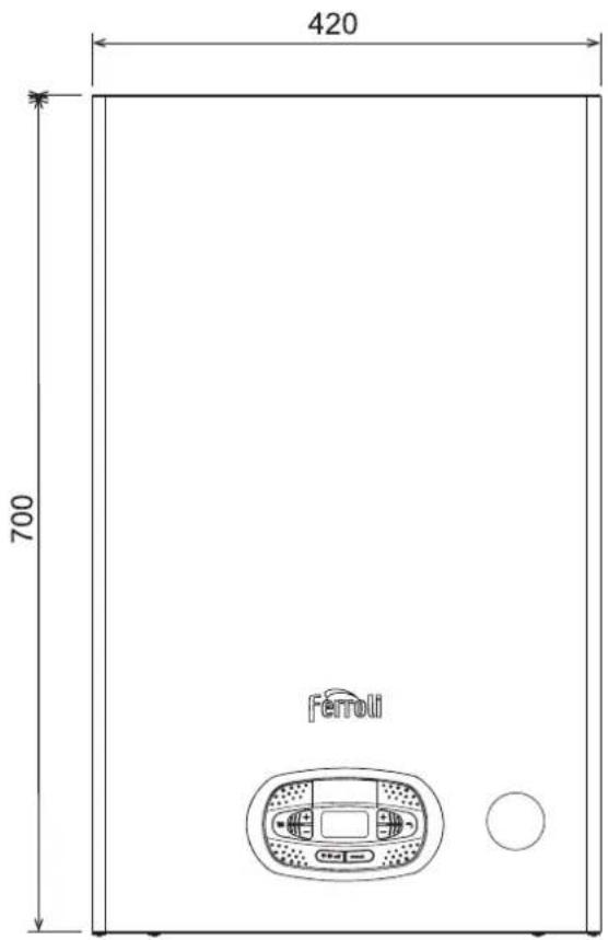
fig. 53- Front view
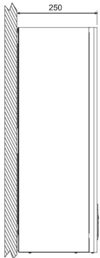
fig. 54- Side view
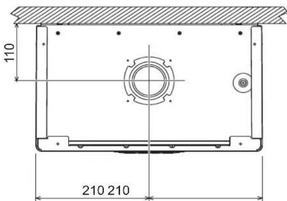
fig. 55- Top view

fig. 56- Bottom view
7 Gas inlet - ∅ 3/4" (22mm with Isolation valve fitted)
8 DHW outlet - ∅ 1/2" (15mm with outlet union fitted)
9 Cold water inlet - ∅ 1/2" (15mm with Isolation valve fitted)
10 System Flow - ∅ 3/4" (22mm with Isolation valve fitted)
11 System Return - ∅ 3/4"(22mm with Isolation valve fitted)
A6 Condensate discharge connection (Flexible adaptor supplied)
4.2 General view

fig. 57- General view
14 Pressure relief valve
16 Fan
32 Heating circulating Erp pump
34 Heating temperature sensor
36 Automatic air vent
42 DHW temperature probe
44 Gas valve
56 Expansion vessel
81 Ionisation/ignition electrode
95 Diverter valve
114 Low water pressure switch
136 Flowmeter
145 System pressure gauge
186 Return sensor
191 Flue temperature probe
193 Trap
194 DHW plate heat exchanger
196 Main heat exchanger
350 Fan/Burner assembly
4.3 Hydraulic circuit

flowchart
graph TD
    A["10"] --> B["14"]
    B --> C["8"]
    C --> D["136"]
    D --> E["241"]
    E --> F["95"]
    F --> G["11"]
    G --> H["186"]
    H --> I["56"]
    I --> J["32"]
    J --> K["36"]
    K --> L["193"]
    L --> M["114"]
    M --> N["34"]
fig. 58- Hydraulic circuit
8 Domestic hot water outlet
9 Cold water inlet
10 System Flow
11 System return
14 Pressure relief valve
32 Heating circulating pump
34 Heating temperature sensor
36 Automatic air vent
42 DHW temperature sensor
56 Expansion vessel
95 Diverter valve
114 Low water pressure switch
136 Flowmeter
186 Return sensor
193 Condense trap
194 DHW plate heat exchanger
241 Automatic bypass (inside the pump unit)
4.4 Technical data table
Table. 9- Technical data table
| Data Unit BLUEHELIX TECH RRT 24 C | |||
| PRODUCT IDENTIFICATION CODES 0T3B2BGA | |||
| COUNTRIES OF DESTINATION GB | |||
| GAS CATEGORY II2H3+ (GB) | |||
| Max. heating capacity kW 20.4 Q | |||
| Min. heating capacity kW 5.0 Q | |||
| Max. Heat Output in heating (80/60°C) kW 20.0 | P | ||
| Min. Heat Output in heating (80/60°C) | kW | 4.9 | P |
| Max. Heat Output in heating (50/30°C) kW 21.7 | |||
| Min. Heat Output in heating (50/30°C) | kW | 5.4 | |
| Max. heating capacity in DHW | kW | 25.0 | |
| Min. heating capacity in DHW | kW | 5.0 | |
| Max. Heat Output in DHW | kW | 24.5 | |
| Min. Heat Output in DHW | kW | 4.9 | |
| Efficiency Pmax (80-60°C) | % | 98.1 | |
| Efficiency Pmin (80-60°C) | % | 97.8 | |
| Efficiency Pmax (50-30°C) | % | 106.1 | |
| Efficiency Pmin (50-30°C) | % | 107.5 | |
| Efficiency 30% | % | 109.7 | |
| Gas supply pressure G20 | mbar | 20 | |
| Max. gas flow G20 | m^3/h | 2.65 | |
| Min. gas flow G20 | m^3/h | 0.53 | |
| CO_2-G20 | % | 9 ±0.8 | |
| Gas supply pressure G31 | mbar | 37 | |
| Max. gas flow G31 | kg/h | 1.94 | |
| Min. gas flow G31 | kg/h | 0.39 | |
| CO_2-G31 | % | 10 ±0.8 | |
| NOx emissions class | - | 6 | NOx |
| Max. working pressure in heating | bar | 2.5 | PMS |
| Min. working pressure in heating | bar | 0.8 | |
| Heating adjustment max. temperature | °C | 95 | tmax |
| Heating water content | litres | 2.9 | |
| Heating expansion vessel capacity | litres | 8 | |
| Heating expansion vessel prefilling pressure | bar | 0.8 | |
| Max. working pressure in DHW | bar | 9 | PMW |
| Min. working pressure in DHW | bar | 0.3 | |
| DHW flow rate Δt 25°C | l/min | 14.0 | |
| DHW flow rate Δt 30°C | l/min | 11.7 | D |
| Protection rating | IP | X5D | |
| Power supply voltage | V/Hz | 230V/50Hz | |
| Electrical power input | W | 73 | |
| Empty weight | kg | 28 | |
| Type of unit | C13-C23-C33-C43-C53C63-C83-B23-B33 | ||
| PIN CE |
ErP product fiche
MODEL: BLUEHELIX TECH RRT 24 C
| Trademark: FERROLI | |||
| Condensing boiler: YES | |||
| Low-temperature boiler (**): YES | |||
| B1 Boiler: NO | |||
| Combination heater: YES | |||
| Cogeneration space heater: NO | |||
| Item | Symbol | Unit | Value |
| Seasonal space heating energy efficiency class (from A++ to G) | A | ||
| Rated heat output | Pn | kW | 20 |
| Seasonal space heating energy efficiency | _s | % | 94 |
| Useful heat output | |||
| Useful heat output at rated heat output and high-temperature regime (*) | P4 | kW | 20,0 |
| Useful heat output at 30% of rated heat output and low-temperature regime (**) | P1 | kW | 4,2 |
| Useful efficiency | |||
| Useful efficiency at rated heat output and high-temperature regime (*) | _4 | % | 88,3 |
| Useful efficiency at 30% of rated heat output and low-temperature regime (**) | _1 | % | 98,8 |
| Auxiliary electricity consumption | |||
| At full load | elmax | kW | 0,022 |
| At part load | elmin | kW | 0,010 |
| In standby mode | PSB | kW | 0,003 |
| Other items | |||
| Standby heat loss | Pstby | kW | 0,042 |
| Ignition burner power consumption | Pign | kW | 0,000 |
| Annual energy consumption | QHE | GJ | 38 |
| Sound power level | LWA | dB | 49 |
| Emissions of nitrogen oxides | NOx | mg/kWh | 38 |
| For combination heaters | |||
| Declared load profile | XL | ||
| Water heating energy efficiency class (from A to G) | A | ||
| Daily electricity consumption | Qelec | kWh | 0,154 |
| Annual electricity consumption | AEC | kWh | 34 |
| Water heating energy efficiency | _wh | % | 86 |
| Daily fuel consumption | Qfuel | kWh | 22,566 |
| Annual fuel consumption | AFC | GJ | 18 |
(*) High-temperature regime means 60°C return temperature at heater inlet and 80°C feed temperature at heater outlet.
(**) Low temperature means for condensing boilers 30°C, for low-temperature boilers 37°C and for other heaters 50°C return temperature (at heater inlet).
4.5 Diagrams
Residual head available for system
BLUEHELIX TECH RRT 24 C

line
| Q (m3/h) | H(mCA) | | -------- | ------ | | 00.10 | 6.7 | | 0.20 | 6.7 | | 0.30 | 6.7 | | 0.40 | 6.7 | | 0.50 | 6.7 | | 0.60 | 6.7 | | 0.70 | 6.7 | | 0.80 | 6.7 | | 0.90 | 6.7 | | 1.10 | 6.5 | | 1.20 | 6.2 | | 1.30 | 5.8 | | 1.40 | 5.3 | | 1.50 | 4.8 | | 1.60 | 4.3 | | 1.80 | 3.5 | | 2.00 | 2.8 | | 2.20 | 2.2 | | 2.40 | 1.8 | | 2.60 | 1.5 | | 2.80 | 1.2 | | 3.00 | 1.0 | | 3.20 | 0.8 | | 3.40 | 0.6 | | 3.60 | 0.4 | | 3.80 | 0.2 | | 4.00 | 0.1 |fig. 59- Residual head available for system
4.6 Wiring diagram
16 Fan
32 Heating circulating pump
34 Heating temperature sensor
42 DHW temperature sensor
44 Gas valve
72 Smart thermostat option (not supplied)
81 Ionistion/ignition electrode
95 Diverter valve
114 Low water pressure switch
136 Flowmeter
138 OTC external sensor (option)
139 OpenTherm Smart thermostat (optional)
186 Return sensor
191 Flue temperature sensor
A ON/OFF switch (configurable)

fig. 60- Wiring diagram

Attention: Remove the jumper on the terminal block before connecting the room thermostat or the remote timer control.
To comply with the Government "Boiler plus scheme" you can connect a "smart thermostat" to control the heating demand. Connect the smart thermostat to terminals 5-6 (72) It must be low voltage or OpenTherm compliant (139).
ALL CONNECTIONS TO THE TERMINAL BLOCK MUST BE WITH VOLTAGE-FREE CONTACTS (NOT 230V).
Benchmark Commissioning and Servicing Section
It is a requirement that the boiler is installed and commissioned in accordance with manufacturer's instructions and the data fields on the commissioning checklist are completed in full.
To validate the boiler guarantee the boiler needs to be registered with the manufacturer within one month of the installation.
To maintain the boiler guarantee it is essential that the boiler is serviced annually by a Gas Safe registered engineer who has been trained on the boiler installed. The service details should be recorded on the Benchmark Service Interval Record and left with the householder.

www.centralheating.co.uk
GAS BOILER SYSTEM COMMISSIONING CHECKLIST
This Commissioning Checklist is to be completed in full by the competent person who commissioned the boiler as a means of demonstrating compliance with the appropriate Building Regulations and then handed to the customer to keep for future reference.
Failure to install and commission according to the manufacturer's instructions and complete this Benchmark Commissioning Checklist will invalidate the warranty. This does not affect the customer's statutory rights.
| Customer name: Telephone number: | ||||||||||||||||||||||||||||||||
| Address: | ||||||||||||||||||||||||||||||||
| Boiler make and model: | ||||||||||||||||||||||||||||||||
| Boiler serial number: | ||||||||||||||||||||||||||||||||
| Commissioned by (PRINT NAME): Gas Safe register number: | ||||||||||||||||||||||||||||||||
| Company name: Telephone number: | ||||||||||||||||||||||||||||||||
| Company address: | ||||||||||||||||||||||||||||||||
| Commissioning date: | ||||||||||||||||||||||||||||||||
| To be completed by the customer on receipt of a Building Regulations Compliance Certificate*Building Regulations Notification Number (if applicable): | ||||||||||||||||||||||||||||||||
| CONTROLS (tick the appropriate boxes) | ||||||||||||||||||||||||||||||||
| Time and temperature control to heating Room thermostat and programmer/timerLoad/weather compensation | Programmable room thermostatOptimum start control | |||||||||||||||||||||||||||||||
| Time and temperature control to hot water Cylinder thermostat and programmer/timer Combination Combination Boiler | ||||||||||||||||||||||||||||||||
| Heating zone valves Fitted Not required | ||||||||||||||||||||||||||||||||
| Hot water zone valves Fitted Not required | ||||||||||||||||||||||||||||||||
| Thermostatic radiator valves Fitted Not required | ||||||||||||||||||||||||||||||||
| Automatic bypass to system Fitted Not required | ||||||||||||||||||||||||||||||||
| Boiler interlock Provided | ||||||||||||||||||||||||||||||||
| ALL SYSTEMS | ||||||||||||||||||||||||||||||||
| The system has been flushed and cleaned in accordance with BS7593 and boiler manufacturer's instructions Yes | ||||||||||||||||||||||||||||||||
| What system cleaner was used? | ||||||||||||||||||||||||||||||||
| What inhibitor was used? Quantity litres | ||||||||||||||||||||||||||||||||
| Has a primary water system filter been installed? Yes No | No | |||||||||||||||||||||||||||||||
| CENTRAL HEATING MODE measure and record: | ||||||||||||||||||||||||||||||||
| Gas rate | m³/hr | OR ft³/hr | ||||||||||||||||||||||||||||||
| Burner operating pressure (if applicable) | mbar | OR Gas inlet pressure | mbar | |||||||||||||||||||||||||||||
| Central heating flow temperature °C | ||||||||||||||||||||||||||||||||
| Central heating return temperature °C | ||||||||||||||||||||||||||||||||
| COMBINATION BOILERS ONLY | ||||||||||||||||||||||||||||||||
| Is the installation in a hard water area (above 200ppm)? Yes No | No | |||||||||||||||||||||||||||||||
| If yes, has a water scale reducer been fitted? Yes No | No | |||||||||||||||||||||||||||||||
| What type of scale reducer has been fitted? | ||||||||||||||||||||||||||||||||
| DOMESTIC HOT WATER MODE Measure and Record: | ||||||||||||||||||||||||||||||||
| Gas rate | m³/hr | OR ft³/hr | ||||||||||||||||||||||||||||||
| Burner operating pressure (at maximum rate) | mbar OR Gas inlet pressure at maximum rate mbar | |||||||||||||||||||||||||||||||
| Cold water inlet temperature °C | ||||||||||||||||||||||||||||||||
| Hot water has been checked at all outlets Yes Temperature °C | Yes | Temperature °C | ||||||||||||||||||||||||||||||
| Water flow rate l/min | ||||||||||||||||||||||||||||||||
| CONDENSING BOILERS ONLY | ||||||||||||||||||||||||||||||||
| The condensate drain has been installed in accordance with the manufacturer's instructions and/or BS5546/BS6798 Yes | ||||||||||||||||||||||||||||||||
| ALL INSTALLATIONS | ||||||||||||||||||||||||||||||||
| Record the following: | At max. rate: CO ppmAt min. rate: (where possible) CO ppmMandatory Requirement CO2 @Max Rate % CO2 @Min Rate % AND CO/CO2 RatioThe heating and hot water system complies with the appropriate Building Regulations YesThe boiler and associated products have been installed and commissioned in accordance with the manufacturer's instructions YesThe operation of the boiler and system controls have been demonstrated to and understood by the customer YesThe manufacturer's literature, including Benchmark Checklist and Service Record, has been explained and left with the customer YesCommissioning Engineer's SignatureCustomer's Signature(To confirm satisfactory demonstration and receipt of manufacturer's literature) | At max. rate: CO ppmAt min. rate: (where possible) CO ppmMandatory Requirement CO2 @Max Rate % CO2 @Min Rate % AND CO/CO2 RatioThe heating and hot water system complies with the appropriate Building Regulations YesThe boiler and associated products have been installed and commissioned in accordance with the manufacturer's instructions YesThe operation of the boiler and system controls have been demonstrated to and understood by the customer YesThe manufacturer's literature, including Benchmark Checklistand Service Record, has been explained and left with the customer Yes | At max. rate: CO ppmAt min. rate: (where possible) CO ppmMandatory Requirement CO2 @Max Rate % CO2 @Min Rate % AND CO/CO2 RatioThe heating and hot water system complies with the appropriate Building Regulations YesThe boiler and associated products have been installed and commissioned in accordance with the manufacturer's instructions YesThe operation of the boiler and system controls have been demonstrated to and understood by the customer YesThe manufacturer's literature, including Benchmark Checklist andService Record, has been explained and left with the customer Yes | At max. rate: CO ppmAt min. rate: (where possible) CO ppmMandatory Requirement CO2 @Max Rate % CO2 @Min Rate % AND CO/CO2 RatioThe heating and hot water system complies with the appropriate Building Regulations YesThe boiler and associated products have been installed and commissioned in accordance with the manufacturer's instructions YesThe operation of the boiler and system controls have been demonstrated to and understood by thecustomer YesThe manufacturer's literature, including Benchmark Checklist andService Record, has been explained and left with the customer Yes | At max. rate: CO ppmAt min. rate: (where possible) CO ppmMandatory Requirement CO2 @Max Rate % CO2 @Min Rate % AND CO/CO2 RatioThe heating and hot water system complies with the appropriate Building Regulations YesThe boiler and associated products have been installed and commissioned in accordance with the manufacturer's instructions YesThe operation of the boilerand system controls have been demonstrated to and understood by the customer YesThe manufacturer's literature, including Benchmark Checklist andService Record, has been explained and left with the customer Yes | At max. rate: CO ppmAt min. rate: (where possible) CO ppmMandatory Requirement CO2 @Max Rate % CO2 @Min Rate % AND CO/CO2 RatioThe heating and hot water system complies with the appropriate Building Regulations YesThe boiler and associated products have been installed and commissioned in accordancewith the manufacturer's instructions YesThe operation of the boiler and system controls have been demonstrated to and understood by the customer YesThe manufacturer's literature, including Benchmark Checklist andService Record, has been explained and left with the customer Yes | At max. rate: CO ppmAt min. rate: (where possible) CO ppmMandatory Requirement CO2 @Max Rate % CO2 @Min Rate % AND CO/CO2 RatioThe heating and hot water system complies with the appropriate Building Regulations YesThe Boiler and associated products have been installed and commissioned in accordance with the manufacturer's instructions YesThe operation of the boiler and system controls have been demonstrated to and understood by the customer YesThe manufacturer's literature, including Benchmark Checklist andService Record, has been explained and left with the customer Yes | At max. rate: CO ppmAt min. rate: (where possible) CO ppmMandatory Requirement CO2 @Max Rate % CO2 @Min Rate % AND CO/CO2 RatioThe heating and hotwater system complies with the appropriate Building Regulations YesThe boiler and associated products have been installed and commissioned in accordance with the manufacturer's instructions YesThe operation of the boiler and system controls have been demonstrated to and understood by the customer YesThe manufacturer's literature, including Benchmark Checklist andService Record, has been explained and left with the customer Yes | At max. rate: CO ppmAt min. rate: (where possible) CO ppmMandatory Requirement CO2 @Max Rate % CO2 @Min Rate% AND CO/CO2 RatioThe heating and hot water system complies with the appropriate Building Regulations YesThe boiler and associated products have been installed and commissioned in accordance with the manufacturer's instructions YesThe operation of the boiler and system controls have been demonstrated to and understood by the customer YesThe manufacturer's literature, including Benchmark Checklist andService Record, has been explained and left with the customer Yes | At max. rate: CO ppmAt min. rate: (where possible) CO ppmMandatory Requirement Co2 @Max Rate % CO2 @Min Rate% AND CO/CO2 RatioThe heating and hot water system complies with the appropriate Building Regulations YesThe boiler and associated products have been installed and commissioned in accordance with the manufacturer's instructions YesThe operation of the boiler and system controls have been demonstrated to and understood by the customer YesThe manufacturer's literature, including Benchmark Checklist andService Record, has been explained and left with the customer Yes | At max. rate: CO ppmAt min. rate: (where possible) CO ppmMandatory Requirement CO2 @Max Rate % CO2 @Min Rate% AND CO/CO2 RatioThe heating and hot water system complies with the appropriate Building Regulations YesThe boiler and associated products have been installed and commissioned in accordance with the manufacturer's instructions YesThe operation of the boiler and system controls have been demonstrated to and understood by the customer YesThe manufacturer's literature, including Benchmark Checklist andService Record, has been explained and left with the customer Yes | |||||||||||||||||||||
| At max. rate: CO ppmAt min. rate: (where possible) CO ppmMandatory Requirement CO2 @Max Rate % CO2 @Min Rate% AND CO/CO2 RatioThe heating and hot water system complies with the appropriate Building Regulations YesThe boiler and associated products have been installed and commissioned in accordance with the manufacturer's instructions YesThe operation of the boiler and system controls have been demonstrated to and understood by the customer YesThe manufacturer's literature, including Benchmark Checklist and Service Record, has been explained and left with the customer Yes | ||||||||||||||||||||||||||||||||
All installations in England and Wales must be notified to Local Authority Building Control (LABC) either directly or through a *Competent Persons Scheme. A Building Regulations Compliance Certificate will then be issued to the customer.
It is necessary that your heating system is serviced annually to validate your warranty and that the appropriate Service Interval Record is completed.
Service Provider
Before completing the appropriate Service Record below, please ensure you have carried out the service as described in the manufacturer's instructions. Always use the manufacturer's specified spares when replacing parts.
| SERVICE 01 | Date: | |||||
| Engineer name: | ||||||
| Company name: | ||||||
| Telephone No: | ||||||
| Gas safe register No: | ||||||
| Record: | At max. rate: | CO ppm | AND | CO2% | ||
| At min. rate: | CO ppm | AND | CO2% | |||
| CO/CO2Ratio min. rate | max rate | |||||
| Comments: | ||||||
| Signature | ||||||
| SERVICE 03 | Date: | |||||
| Engineer name: | ||||||
| Company name: | ||||||
| Telephone No: | ||||||
| Gas safe register No: | ||||||
| Record: | At max. rate: | CO ppm AND CO | 2% | |||
| At min. rate: | CO ppm AND CO | 2% | ||||
| CO/CO2 Ratio min. rate max rate | ||||||
| Comments: | ||||||
| Signature | ||||||
| SERVICE 05 | Date: | |||||
| Engineer name: | ||||||
| Company name: | ||||||
| Telephone No: | ||||||
| Gas safe register No: | ||||||
| Record: | At max. rate: | CO ppm AND | CO | 2% | ||
| At min. rate: | CO ppm AND | CO | 2% | |||
| CO/CO2 Ratio min. rate max rate | ||||||
| Comments: | ||||||
| Signature | ||||||
| SERVICE 07 | Date: | ||||||
| Engineer name: | |||||||
| Company name: | |||||||
| Telephone No: | |||||||
| Gas safe register No: | |||||||
| Record: | At max. rate: | CO ppm AND CO | 2% | ||||
| At min. rate: | CO ppm AND CO | 2% | |||||
| CO/CO2 Ratio min. rate max rate | |||||||
| Comments: | |||||||
| Signature | |||||||
| SERVICE 09 | Date: | ||||||
| Engineer name: | |||||||
| Company name: | |||||||
| Telephone No: | |||||||
| Gas safe register No: | |||||||
| Record: | At max. rate: | CO ppm AND CO | 2% | ||||
| At min. rate: | CO ppm AND CO | 2% | |||||
| CO/CO2 Ratio min. rate max rate | |||||||
| Comments: | |||||||
| Signature | |||||||
| SERVICE 02 | Date: | |||||
| Engineer name: | ||||||
| Company name: | ||||||
| Telephone No: | ||||||
| Gas safe register No: | ||||||
| Record: | At max. rate: | CO ppm AND | CO | 2% | ||
| At min. rate: | CO ppm AND | CO | 2% | |||
| CO/CO2Ratio min. rate | max rate | |||||
| Comments: | ||||||
| Signature | ||||||
| SERVICE 04 | Date: | ||||||
| Engineer name: | |||||||
| Company name: | |||||||
| Telephone No: | |||||||
| Gas safe register No: | |||||||
| Record: | At max. rate: | CO ppm AND CO | 2% | ||||
| At min. rate: | CO ppm AND CO | 2% | |||||
| CO/CO2Ratio min. rate max rate | |||||||
| Comments: | |||||||
| Signature | |||||||
| SERVICE 06 | Date: | |||||
| Engineer name: | ||||||
| Company name: | ||||||
| Telephone No: | ||||||
| Gas safe register No: | ||||||
| Record: | At max. rate: | CO ppm AND CO | 2% | |||
| At min. rate: | CO ppm AND CO | 2% | ||||
| CO/CO2Ratio min. rate max rate | ||||||
| Comments: | ||||||
| Signature | ||||||
| SERVICE 08 | Date: | |||||
| Engineer name: | ||||||
| Company name: | ||||||
| Telephone No: | ||||||
| Gas safe register No: | ||||||
| Record: | At max. rate: | CO ppm AND | CO | 2% | ||
| At min. rate: | CO ppm AND | CO | 2% | |||
| CO/CO2Ratio min. rate max rate | ||||||
| Comments: | ||||||
| Signature | ||||||
| SERVICE 10 | Date: | ||||
| Engineer name: | |||||
| Company name: | |||||
| Telephone No: | |||||
| Gas safe register No: | |||||
| Record: | At max. rate: | CO ppm | AND | CO2% | |
| At min. rate: | CO ppm | AND | CO2% | ||
| CO/CO2Ratio | min. rate | max rate | |||
| Comments: | |||||
| Signature | |||||
Before contacting Ferroli please have available the completed BENCHMARK document (located in the back of this manual), boiler serial number and model detail.
For Technical assistance during the installation, call our
Technical Helpline on 0330 205 0005
You will be required to provide your Gas Safe Register Number.
Should you require a Service Engineer to visit, call our
Service Centre on 0330 205 0005
Calls to our 0330 numbers cost the same as a call to an 01 or 02 national number whether from a landline or mobile.
Calls are also inclusive in any bundle you may have with have your phone provider.
Phone numbers:
Installer
Service Engineer
BECAUSE OF OUR CONSTANT ENDEAVOUR FOR IMPROVEMENT DETAILS MAY VARY SLIGHTLY FROM THOSE QUOTED IN THESE INSTRUCTIONS.
ALL SPECIFICATIONS SUBJECT TO CHANGE
Please note - to avoid incurring unnecessary expense, in the event of a boiler shut down, check this is not caused by lack of electricity supply, gas supply or low water pressure before calling our Customer Service Helpline

FERROLI S.p.A.
Via Ritonda 78/a
37047 San Bonifacio - Verona - Italy
www.ferroli.com
Made in Italy
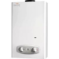



- BLUEHELIX TECH RRT 24 C
- Operating instructions .... 4
- Installation....10
- Service and maintenance....21
- Technical data and characteristics .... 45
- 39Operating instructions
- Introduction
- Control panel
- Panel legend fig. 1
- Indication during operation
- Heating
- Domestic hot water (DHW)
- Comfort
- Fault
- Connection to the power supply, switching on and off
- Boiler not electrically powered
- Boiler electrically powered
- Electronically turning the boiler off and on
- Adjustments
- Winter/summer switchover
- Heating temperature adjustment
- DHW temperature adjustment
- Room temperature adjustment (with optional room thermostat)
- Room temperature & time adjustment (with optional room thermostat)
- ECO/COMFORT selection
- Outside Temperature Compensation (OTC)
- Compensation curve and curve offset
- Adjustments from Remote Timer Control
- System draining
- Installation
- General Instructions
- Safe handling of materials
- Advice for transport and handling
- Place of installation
- Plumbing connections
- Important
- Typical System By-pass layout
- Make up water
- Key
- Isolation valve kit
- Antifreeze system, antifreeze fluids, additives and inhibitors
- System water characteristics
- Recommended chemical conditioners:
- Gas connection
- Electrical connections
- Room thermostat (optional)
- Accessing the electrical terminal block and fuse
- Flue ducts
- Connection with concentric chimney flues
- Backflow preventer valve
- Condensate drain connection
- Condensate drain
- Service and maintenance
- Adjustments
- Gas conversion
- MAKE SURE THE FRONT CASING IS CLOSED AND THE INTAKE/FUME EXHAUST DUCTS ARE COMPLETELY ASSEMBLED
- Checking the combustion values
- 100% calibration
- 100% calibration, manual
- Calibration procedure.
- 100% calibration, automatic
- Loading parameters with "BCC KEY"
- TEST mode activation
- Perform a heating or DHW demand.
- Heating power adjustment
- Service menu
- ONLY FERROLI TRAINED PERSONNEL CAN ACCESS THE SERVICE MENU AND MODIFY PARAMETERS.
- “tS” - Engineers Parameters Menu
- Notes:
- Procedure for modifying parameter SC12:
- Procedure for modifying parameters SC12 and SC13:
- "In" - Information Menu
- "Hi" - History Menu
- "rE" - History Reset
- Commissioning
- Before lighting the boiler
- First boiler ignition
- Maintenance
- Opening the front panel
- Annual Boiler Service
- Replacement of major components & testing
- Gas valve
- Plate heat exchanger
- Circulating pump
- Replacing the main exchanger
- Exchanger insulation replacement
- Fan
- Removing the diverter valve motor head
- Replacing the Low water pressure switch
- Cleaning or replacing the flowmeter
- Troubleshooting
- Diagnostics
- Blank LCD
- LCD Fault codes
- Fault code Table
- Technical data and characteristics
- Dimensions and connections
- Technical data table
- ErP product fiche
- Diagrams
- Wiring diagram
- Benchmark Commissioning and Servicing Section
- GAS BOILER SYSTEM COMMISSIONING CHECKLIST
- Service Provider
Brand : FERROLI
Model : Bluehelix Tech RRT 24C
Category : Boiler