USER MANUAL I CLEAN 100 HARPER
Split Wall-Mounted Series Air-Conditioners
CONTENTS
Chapter 1 photos and Features of products
Chapter 2 Operating Principle
Chapter 3 operation details
Chapter 4 Exploded Views of the Production
Chapter 5 Main Technical Data
Chapter 6 Dismantling Procedure
Chapter 7 Brief introduction of installation
Chapter 8 Fault Analysis of the Product Available
ASW-H07B4/HSAR
ASW-07B4/HSAR
ASW-H09A4/HSAR
ASW-09A 4/HSAR
Deep × width × high 165x802x262
ASW-H07B4/HSR
ASW-07B4/HSR
ASW-H09A 4/HSR
ASW-09A 4/HSR
Deep × width × high 165x802x262
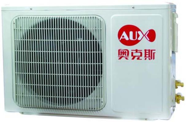
Deep × width × high 260× 760× 540
All types
All types
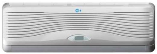
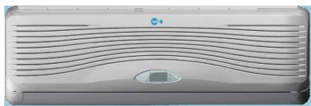
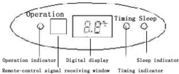
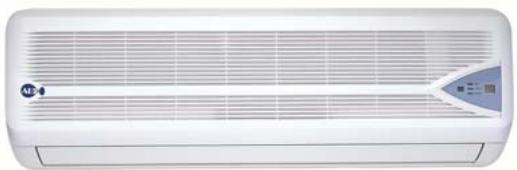
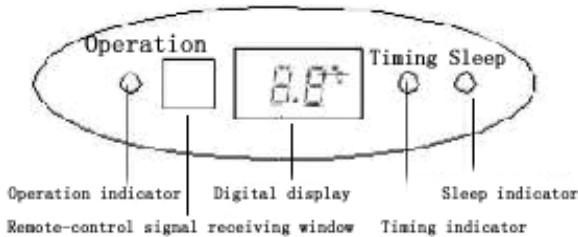
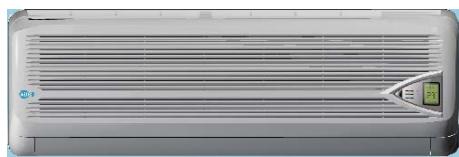
Operation interface
Inner operation interface of Type HSAR
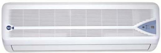
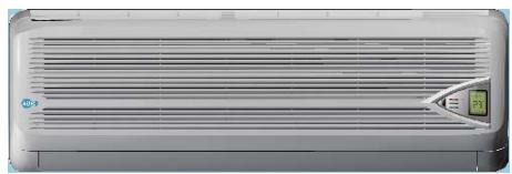
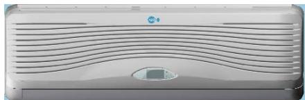
Inner operation interface of Type HSR
Emergency operation button of indoor types:
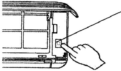
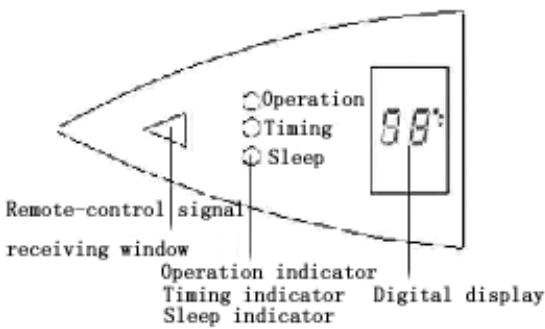
1) When the air-conditioner works with the absence of remote control, it will stop working by pressing the compulsory button and it will resume working by pressing the compulsory button once again.
2) When remote control is useless, you can adopt the compulsory operation by which the air conditioner will go into automatic operation mode.
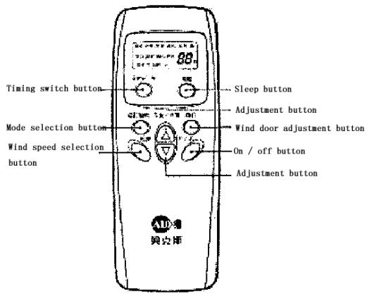
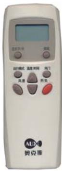
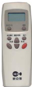
The operation interface of remote control:
Features of products
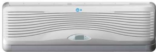
- Fashionable appearance
- Compact Design
3.7 Hours of Sleep Mode Operation
- Economy Mode to Reduce Electrical Power Consumption
- Clean breath efficient biological antibacterial filter gauze made from green plant elite refined by using international leading technology, with the function of filtering and suppressing bacteria, and able to absorb and kill various pathogens and harmful gases efficiently for a long period, prevent secondary pollution caused due to microorganism spreading, and ensure the health of your family
- R407c cold medium is applied, environment-friendly, and avoid damages to ozonosphere
- International famous-brand Toshiba Hitachi and Matsushita compressors are applied
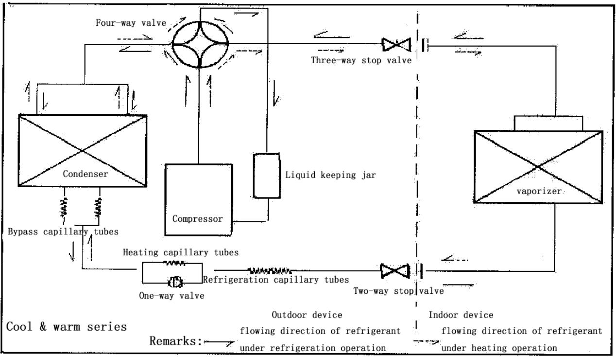
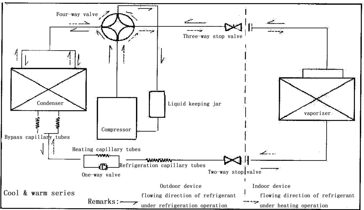
Chapter 2 Operating Principle
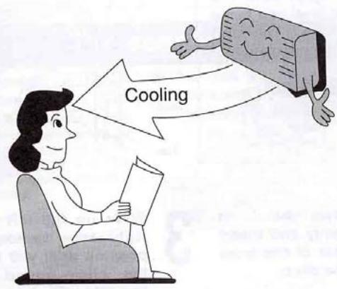
. Cooling
After the power supply is switched on, the machine is set to COOL mode. With the compressor being operated, the low-temperature and low-pressure refrigerant vapor is sucked into the compressor where it is
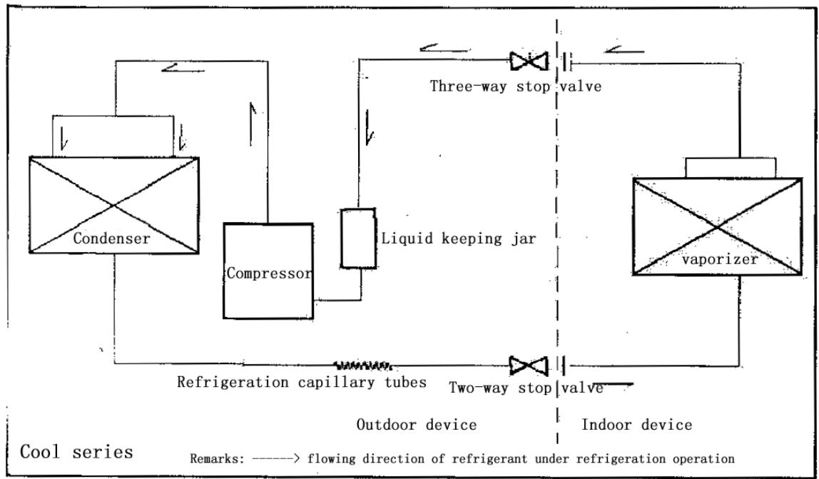
turned into high-temperature and high-pressure gas. Then it is cooled down in the outdoor heat exchanger by the air and becomes liquid. After being throttled by the capillary, the refrigerant liquid comes into the indoor unit and then it evaporates in the indoor heat, exchanger, absorbing heat and reducing the room temperature. The evaporated refrigerant vapor returns to the outdoor unit and is again sucked into the compressor, completing the cycle. With the refrigerant cycling being kept on, the objective of lowering the room temperature is fulfilled.
. Heating
After the power supply is switched on, the machine is set to HEAT mode and the coil of the electromagnetic four-way valve is energized. After the compressor starts to operate, the high-temperature and high-pressure refrigerant gas first comes into the heat exchanger of the indoor unit, where it is cooled, releases heat and increases the room temperature. The cooled high-pressure refrigerant is then throttle1d in the outdoor unit and returns to the compressor after evaporation. With such cycles being maintained, the objective of increasing the room temperature is fulfilled.
Operation Hints
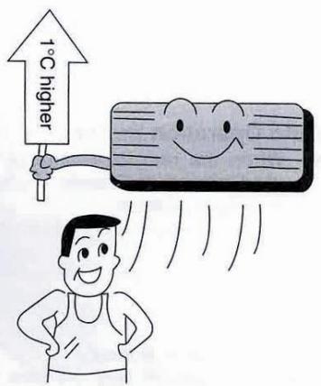
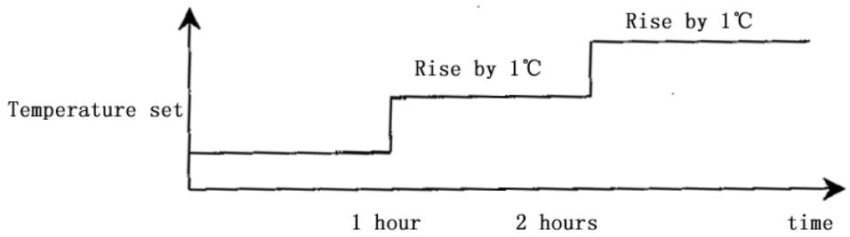
Adjust room temperature properly. Set the temperature 1^ higher than actually desired. Approximately 10% of electricity costs can be saved.
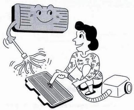
Clean the air filter regularly. Blockage in the air filter reduces the airflow and lowers the cooling. Clean at least once every 2 weeks. Otherwise, 6% of electricity cost will be wasted.
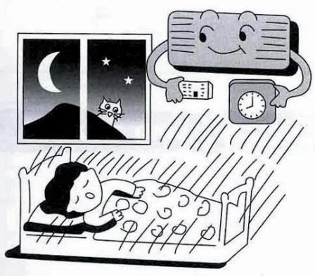
Prevent waste with the Timer. Use Timer when sleeping or going out to save electricity cost.
Do not block the air outlet vents at outdoor unit. Otherwise, it will lower the cooling performance.

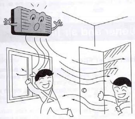
Make sure that the doors and windows are shut. Otherwise, cooling performance will be reduced and electricity cost is wasted.
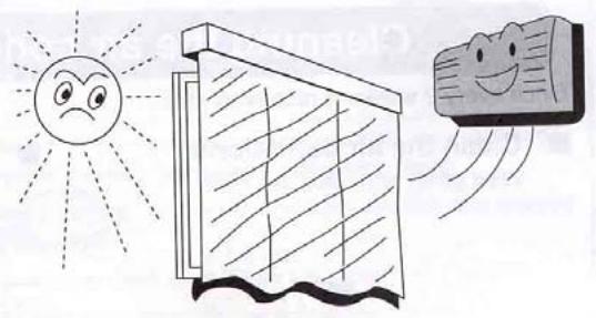
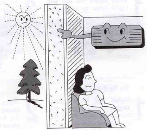
Keep blinds or curtains closed. Do not let sunshine enter the room directly. 5% of electricity cost can be saved.
Proper airflow direction adjustment. Set the airflow direction louvers horizontal for Cooling Operation. Operation result will be better.
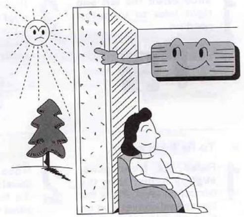
Use insulating material for better performance. Use insulating material during construction or renovations. It will save electricity cost.

Chapter 3 operation details
1. Overall
1.1 Protection of compressor
Whatever operation modes the air-conditioner is under, there will always be 3 minutes' time-delay protection unless it is on for the first time. When the compressor is switched on, it can not be shut down within 3 minutes (except under the modes of heating or defrosting) unless it is powered off or its operation mode is changed.
1.2 The operation indicator will turn light when the air conditioner is powered on.
1.3 The buzzer will sound immediately after the controlling device receives a correct and effective signal sent by the remote control.
1.4 Timing function can be applicable to all operation modes while sleep function can only be applicable to the modes of refrigeration and heating.
2. Automatic operation mode
2.1 When the air conditioner works, it can detect the indoor temperature automatically whereby its operation mode can be selected: refrigeration, heating or dehumidification.
2.2 When the indoor temperature reaches more than 27, the air conditioner will operate under the mode of refrigeration.
2.3 When the indoor temperature reaches between 20 and 27 the air
conditioner will work under the mode of dehumidification (always mute).
2.4 When the indoor temperature reaches less than 20, the air conditioner will work under the mode of heating.
2.5 Under this mode, the air conditioner will operate in the respect of blowing rate as set and its pendulum leaves will work according to the requirements of automatic ventilation door.
2.6 Once the operation mode is selected, it will not be able to be changed. When the air conditioner is shut down and then restarted, the operation mode will be selected once again based on the variation of indoor temperature.
2.7 After the operation indicator has been flickering for 20 seconds, it will turn light steadily (i.e. the determination of operation mode will start in 20 seconds.)
2.8 This mode has timing function, does not have sleep function.
2.9 Under this operation mode, the temperature can be set and adjusted by remote control.
3. Refrigeration mode
3.1 Under the refrigeration mode, the range of temperature set by remote control is between 16 and 32.
3.2 Shut-down of four-way valve;
3.3 The condition on which the compressor starts is that the indoor
temperature reaches more than the temperature set plus 1 while the condition on which the compressor shuts down is that the indoor temperature reaches less than the temperature set minus 1 .And when the indoor temperature is equal to that set, the original operation mode will be kept.
3.4 Under the mode of refrigeration, the function of preventing indoor coiled pipe from being frozen will be effective.
3.5 The indoor wind speed will be as set. And the pendulum leaves will work according to the instructions sent by remote control.
4. Dehumidification operation
4.1 The temperature range set and controlled is between 16 and 32 . The temperature will be set by remote control.
4.2 The four-way valve is shut down.
4.3 The wind speed gear-changes to "mute". And the pendulum leaves works according to the instructions sent by remote control;
4.4 The function of preventing indoor coiled pipe from being frozen is effective.
4.5 When the indoor temperature reaches less than 16, the function of dehumidification is out of use.
4.6 When the indoor temperature reaches more than 16, the compressor will be switched on and work intermittently. The time when the compressor shuts down depends on T ring and T ring-T set.
When the compressor is shut down, the outdoor fan and indoor fan will stop working.
When T ring ≥ 23
T set < T ring-1, the compressor will be working for 8 minutes and then stopping for 3 minutes in cycles.
T set≥T ring-1, the compressor will be working for 3 minutes and then stopping for 6 minutes in cycles.
And when T ring < 23
T set ≤ T ring-1, the compressor will be working for 3 minutes and then stopping for 4 minutes in cycles.
T set >T ring-1, the compressor will be working for 3 minutes and then stopping for 6 minutes in cycles.
5. Function of ventilation control
5.1 Under the mode of ventilation, the outdoor fan assembly will always be shut down.
5.2 The indoor fan will operate as set in the respect of air quantity without the gear- change of "high power".
5.3 The pendulum leaves will work according to the instructions sent by remote control.
6. Heating function
6.1 Under the mode of heating, the temperature range set is between 16 and 32. And the temperature will be set by remote control.
6.2 When the air conditioner is powered on, the outdoor fan, four- way valve and compressor will start at the same time while when it is shut down, the outdoor fan and compressor will be shut down at the same time and so will the four- way valve after 2 minutes' delay.
6.3 Under the mode of heating, the compressor can not be shut down within 3 minutes after it is powered on unless the operation mode is changed or the air conditioner is turned off.
6.4 There is a 3-temperature compensating function. The temperature measured at the in-blow vent minus 3 automatically can be regarded as that compared with the temperature set (This function does not exist under other circumstances).
6.5 According to the temperature set, the condition upon which the compressor will be switched on is indoor temperature ≤ temperature set-1 While the condition upon which it will be switched off is indoor temperature is indoor temperature ≥ temperature + 1 . When the indoor temperature is equal to that set, the original operation mode will be kept.
6.6 Indoor fan control:
6.6.1 Heating operation and prevention of cold wind
When the compressor works:
- During the rising process of the temperature of coiled pipe, the indoor fan will not start if the temperature of the coiled
pipes is less than 25 .
-
When the temperature of coiled pipe reaches less than 35 But more than 25, The indoor fan will work under the mode of " mute". If the temperature of coiled pipe ascends to 25 and then descends, it will stop working only when the temperature is lowered to 22.
-
When the temperature of coiled pipe reaches more than 35, the indoor fan will operate as set in the respect of wind speed. If the temperature of coiled pipe ascends to 35 And then descends, it will enter into the operation mode of " mute" only when the temperature is lowered to 30 .
6.6.2 Afterheat-blowing function:
6.6.2.1 When the compressor stop working:
- When the temperature of coiled pipe is more than 35, the indoor fan will operate as set in respect of wind speed.
- When the temperature of coiled pipe is more than 25 , but lessthan 35 , The indoor fan will operate under the mode of “ mute"
- When the temperature of coiled pipe is less than 25, the indoor fan will stop working.
6.6.2.2 The afterheat-blowing function when the air conditioner is just shut down: If the temperature of indoor coiled pipe reaches more than 30 , The indoor fan will operate under the mode of “ mute”; If
it lowers to less than 30 , the indoor fan will be shut down; And the
time when the afterheat blows will last less than 40 seconds after
the indoor fan is turned off.
6.7 Defrosting operation:
6.7.1 The conditions upon which the outdoor sensor goes into operation are
as below:
-
Under the circumstance of heating, if T external coiled pipe is at the temperature of less than -6 which lasts 2 minutes and the accumulated working time of compressor reaches more than 50 minutes (if there is any power cut-off or shut-down by remote control, the accumulated working time of compressor shall be re-calculated), the defrosting interval will be more than 50 minutes and the compressor will be working 5 minutes continually.
-
If there is any damage to the external coiled pipe, the accumulated working time of compressor will reach 50 minutes (if there is any power cut-off, shut-down by remote control or defrosting, the accumulated working time of compressor shall be re-calculated) and the defrosting operation will last 10 minutes.
6.7.2 Once one of the following conditions is satisfied, the defrosting will
end:
- The temperature of T external coiled pipe is more than 12 .
- Defrosting duration is more than 12 minutes.
6.7.3 The requirements of defrosting operation:
-
Sleep indicator flickers at the speed of 1 time per second
-
When defrosting operation starts, the compressor and indoor fan will stop working while outdoor fan and four-way valve will continue to work.
-
The four-way valve and outdoor fan will stop operating in 30 seconds.
-
15 seconds after that, the compressor starts and goes into defrosting operation.
-
After the defrosting ends, the compressor stops working. And the four-way valve and outdoor fan begins to work in 20 seconds.
-
20 seconds after that, the compressor starts and goes into heating operation. And the indoor fan enters into the prevention mode of cold wind.
6.8 Auxiliary electric heating function
6.8.1 Only if the following conditions are satisfied under the heating operation, can the auxiliary electric heating go into operation automatically.
a. The compressor works for 4 minutes by heating pump
b. Indoor temperature is less than 22 ;
c. The temperature set-indoor temperature is more than 3 ;
d. Indoor fan goes into operation;
e. Indoor coiled pipe temperature is less than 48
6.8.2 Once one of the following conditions is satisfied, auxiliary electric heating operation will end:
a. Indoor temperature is more than 22 .
b. The temperature set -indoor temperature is less than 2 .
c. When Indoor coiled pipe temperature is more than 52 , theelectric heating operation will end.
d. Indoor temperature sensor becomes abnormal.
6.8.3 If compressor or indoor fan stops working, the electric heating will stop operating as well.
6.8.4 During the operation of compressor, if the auxiliary electric heating stops working, it can be restarted only in 1 minute.
7. Sleep operation
7.1 When the air conditioner enters into the mode of sleep, the indoor wind speed will turn into the air quantity of "mute".
7.2 When the sleep operation goes under the mode of refrigeration, the temperature set rises by 1 automatically every one hour. And the air conditioner will be powered off after sleep mode has worked for 7 hours.
7.3 When the sleep operation goes under the mode of heating, the temperature set drops by 2 automatically every one hour. And the air conditioner will be powered off after sleep mode has worked for 7 hours.
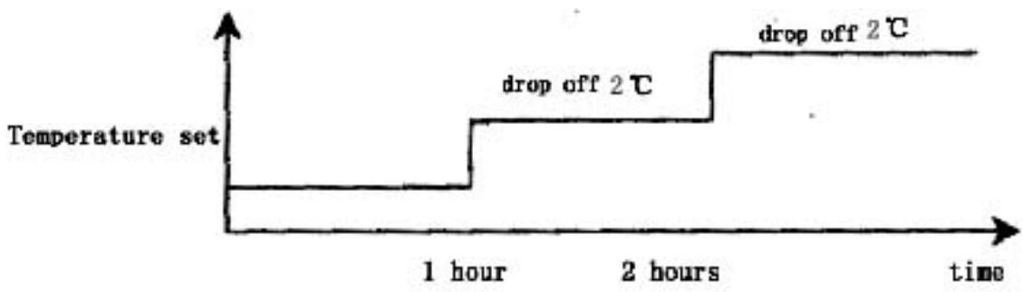
7.4 When the button of mode selection is pressed down, the function of sleep will be cancelled.
7.5 Sleep operation is effective under the modes of refrigeration and heating. When sleep button is pressed down, the sleep operation can begin or end.
7.6 Sleep function does not exist under the automatic mode, the situation of dehumidification or the circumstance of ventilation.
8. Timing operation
8.1 When timing is set, timing indicator will turn light.
8.2 The time set by timing is 12 hours at most. The timing unit is 1 hour. Even if the operation mode is changed, the timing function will still work.
8.3 Power-off at a fixed time
The power-off at a fixed time can be set only if the air conditioner is on. And it continues to work though the power-off at a fixed time has been already set. When it comes to the fixed time, the indoor and outdoor fans will be shut down.
8.4 Power-on at a fixed time
The power-on at a fixed time can be set only if the air conditioner is on. And it continues to be off though the power-on at a fixed time has been already set. When it comes to the fixed time, the indoor and outdoor fans will start to operate.
9. Emergency switch
When the soft-touch switch is pressed, the air conditioner will be powered on and the operation indicator will flicker (1 time per second). And it goes into the mode of automatic operation in 20 seconds. When the soft-touch is pressed once again, it will be powered off. When the air conditioner goes under the mode of automatic operation, the air door will assume the appearance of automatic air door. Under the mode of heating or refrigeration, the temperature set will be 24 and the wind speed will turn that under the "high power" mode. Under the dehumidification operation, the temperature set will be T ring-2 and the air conditioner can work upon the instructions sent by remote control.
10. Overload control and various protection functions:
10.1 Temperature control (overheat protection).
10.1.1 This function can only be applied to the mode of heating, not others.
10.1.2 When the temperature of indoor coiled pipe reaches more than 57, outdoor fan will stop working.
10.1.3 When the temperature of indoor coiled pipe drops to less than 52 , outdoor fan will resume to operate normally.
10.2 Temperature cut-off control function (overheat protection)
10.2.1 This function can only be applied to the mode of heating, not others.
10.2.2 When the temperature of indoor coiled pipe reaches more than 64 which lasts more than 10 seconds, the compressor and outdoor fan will all stop working.
10.2.3 After 3 minutes' shut-down, the compressor will resume to operate if the temperature of indoor coiled pipe drops to less than 52.
10.3 Function of preventing indoor coiled pipe from being frozen (supercooling protection).
10.3.1 This function can only be applied to the operation mode of refrigeration or dehumidification, not others.
10.3.2 When the temperature of indoor coiled pipe drops to -2
which lasts more than 2 minutes, the compressor will stop operating and the indoor fan will go by air quantity set.
10.3.3 When the compressor stops working, it can only be restarted only if the temperature of indoor coiled pipe rises to more than 7 or the power-off of the compressor lasts more than 6 minutes.
10.4 Protection function of short or open circuit of temperature senor
10.4.1 Powered on, when it is detected that the T ring signal sent by indoor environment temperature senor is abnormal, the air conditioner will work under the mode of heating and will not be powered off if the signal received from remote control is “heating” or it will work under the mode of refrigeration and will not be powered off if the signal received from remote control is “refrigeration” or it will work for 8 minutes and then stop for 3 minutes with the wind speed of “mute cycle dehumidification” if the signal received from remote control is “dehumidification”. Besides, the signal of automatic mode sent by remote control will not be effective, nor will the signal of automatic button power-on and the related breakdown can be indicated at the same time.
10.4.2 When it is detected that the T internal coiled pipe signal sent by indoor coiled pipe temperature sensor is abnormal, the freezing-proof, cold-wind-proof and overheat-proof functions
will be screened. Under the mode of heating, when the compressor is powered on, indoor fan will be started after 30 seconds' delay with the wind speed as set while when compressor is powered off, indoor fan will be turned off after 30 seconds' delay and the related breakdown can be indicated at the same time.
10.4.3 When it is detected that the T external coiled pipe signal sent by outdoor coiled pipe temperature sensor is abnormal, the air conditioner will work for 50 minutes, defrost for 10 minutes and heat in cycles if the signal received from remote control is "heating" and the related breakdown can be indicated at the same time while the air conditioner will not be powered off and will operate normally if the signal received from remote control is heating or defrosting or ventilation and the related breakdown can be indicated at the same time.
10.5 disposal of indoor PG electric motor abnormality
When indoor PG electric motor is loaded with voltage, the indoor fan will operate under the mode of "weak wind" automatically if the pulse signal feed backed by the indoor electric motor is not detected within 12 seconds. If the feedback signal detected is normal, the indoor fan will resume the turning speed set and the related breakdown indication will be disappear.
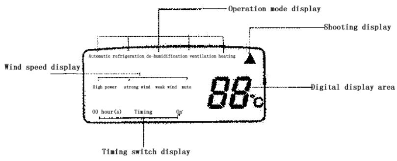
10.6 Function of charatron display
When the controller is normal, there will be no charatron display under the circumstance of power-off. When air conditioner is powered on, the charatron will display room temperature under the normal situation. If the temperature set is changed, the charatron will show the temperature set which sparkles at the rate of 1 time per second. Then it will display room temperature once again in 5 seconds. The display range of room temperature is 0 79 .
11. Function of breakdown indication
HS, HSA series (charatron); HV (VFD display)
| Breakdown cause | Display way | Display priority class |
| PG feedback abnormality | E4 | 1 |
| T ring abnormality | E1 | 2 |
| T internal coiled pipe abnormality | E3 | 3 |
| T external coiled pipe abnormality | E2 | 4 |
12. Adjustment function of air door direction by pendulum leaves
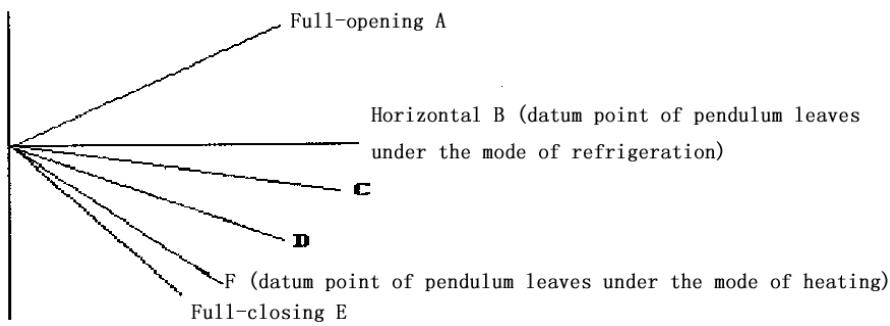
12.1 When the air conditioner is powered on for the first time, the pendulum leaves will move to the direction of full-opening and then to the direction of full-closing wherever they are placed.
12.2 When the air conditioner is powered off, the pendulum leaves will move up to "close" position immediately wherever they are placed after the fan comes to an end.
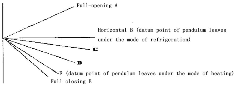
12.3 Under the mode of refrigeration, the pendulum leaves will first move to the full-opening position and then move to the horizontal position and at last move under the mode set while under the mode of heating, they will first move to the full-opening position and then backswing by 5 and at last work under the mode set (for details, please see the following diagram).
12.4 Pendulum wind: automatic air door and manual air door will be controlled by one button.
12.5 When the pendulum leaves move from full-opening position to full-closing position at the time of power-on or from starting position to full-closing position at the time of power-off, the speed will be 20 per second while the speed under the instruction situation will be 5 per second.
Swing angle under the mode of refrigeration: BD is 35 ± 2
Swing angle under the mode of heating: FC is 40 ± 2
Backswing angle under the mode of heating: EF is 5
13. Self-checking function of controller
After the automatic button is pressed, the air conditioner will be powered on and enter into the process of self-checking:
Buzzer sounds two times operation indicator turns on timing indicator turns on compressor acts four-way valve acts outdoor fan acts electric heating acts indoor fan acts buzzer sounds one time which means that air conditioner goes into the state of order-waiting and the self-checking comes to an end.
14. Remote control
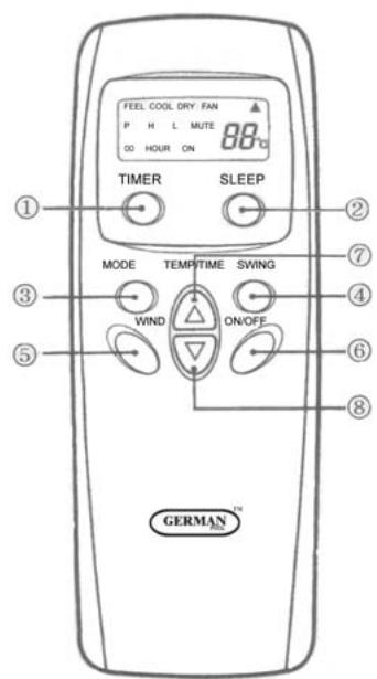
Name and functions of the button on the remote control
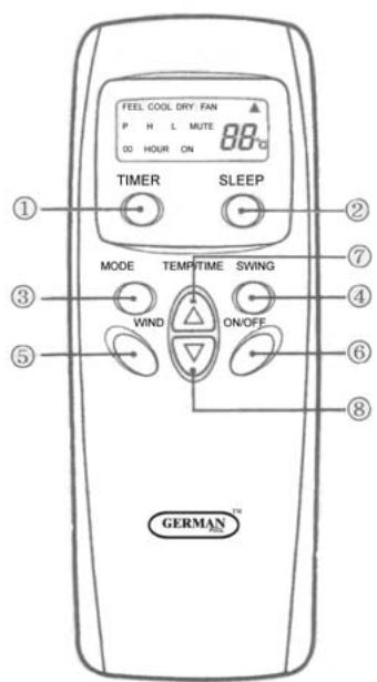
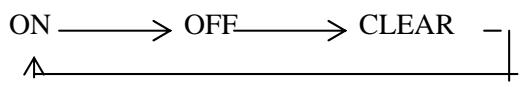
(1) Timing ON/OFF button: set the timing mode. After each pressing, the mode will be changed. It shows in the following display.
(2) Sleeping button: which enables you to start the automatic operation in sleeping mode and stops by pressing on it again.
(3) Selection button for operation mode: which enables you to select different operation modes, after each pressing, the operation mode will be changed. It shows in the following display.

Remarks: Only cool type remote control has no heat mode
(4) Wind direction adjusting button: press the button, the horizontal airflow direction plate can adjust automatically. When you have the desired wind direction, please press it again, the airflow direction plate will maintain the same position.
(5) Fan speed selection button: you can select fan speed from "Power", "High", "Low", and "Mute".

(6) ON/OFF button: you can start the air-conditioner by pressing this button and stop its operation by pressing it again.
(7) Setting button▲: Press the button, the setting temperature or timer
will increase.
(8) Setting button : Press the button, the setting temperature or timer will decrease.
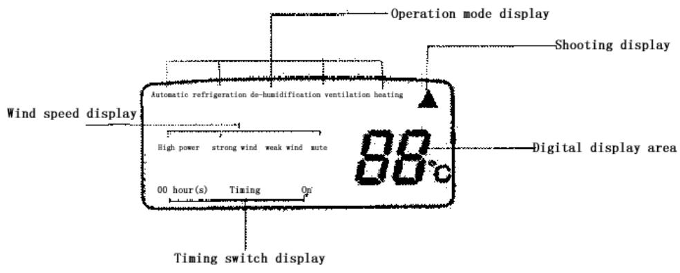
Display
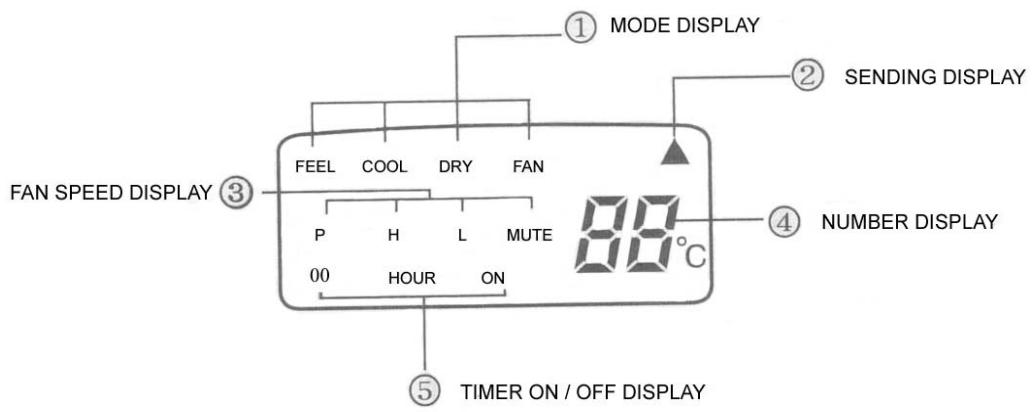
(1) Mode display: press the MODE button, it shows the current operation mode. You can select “Automatic”, “Cool”, “Dry”, and “Fan” “heat” operation mode. (cold wind type has no heating mode)
(2) Sending display: when the remote control sends correct and effective signal each time, the sign displays intermittently each time.
(3) Fan speed display: press the "WIND" button, the fan speed will display. You can select fan speed from "Power", "High", "Low", and "Mute".
(4) Number display: which displays the setting temperature, in the circulation operation mode, the temperature number does not display.
(5)Timer ON/OFF display: which displays the timer states, “the timer ON” and “the timer OFF” do not set at the same time.
Remark: For illustration, all display items are listed here. When the mode operates, the relevant items display on the remote control.
Application
Fix batteries
(1) Slide open the cover according the direction indicated by arrowhead.
(2). Put into two AAA new batteries, position the batteries to right electric poles (+\& -) .
(3)Put back the cover.
Make sure to connect the wire to independent power source socket before you use the remote control.
Automatic operation mode
(1) Press the MODE button, select the automatic operation mode.
(2) Press the TEMP/TIME button, set the temperature, temperature can be set at 1^ difference range from 16 - 32^ .
(3) Press the WIND button, you can select fan speed from "Power", "High", "Low", "Mute".
(4) Press the ON/OFF button, the operation indicator is on, the air-conditioner starts to operate in the Automatic mode.
Press the button again, the air-conditioner stops.
Cooling/heating operation mode (cold wind type has no heating operating)
(1) Press the MODE button, select the Cooling operation mode.
(2) Press the TEMP/TIME button, set the temperature, temperature can be set at 1 difference range from 16 - 32^ C .
(3) Press the WIND button, you can select fan speed from "Power", "High", "Low", "Mute".
(4) Press the ON/OFF button, the operation indicator is on, the air-conditioner starts to operate in the Cooling mode. Press the button again, the air-conditioner stops.
Drying operation mode
(1) Press the MODE button, select the Drying operation mode.
(2) Press TEMP/TIME button, set the temperature, temperature can be set at 1^ difference range from 16 - 32^ .
(3) Press the ON/OFF button, the operation indicator is on, the air-conditioner starts to operate in the Drying mode. Press the button again, the air-conditioner stops.
Remark: In the drying operation mode, the fan speed is automatically set to "Mute".
Circulation operation mode
(1) Press the MODE button, select the Circulation operation mode.
(2) Press the WIND button, you can select fan speed from "High", "Low", "Mute". In the circulation operation mode, you cannot select the speed of "Power".
(3) Press the ON/OFF button, the operation indicator is on, the air-conditioner starts to operate in the Circulation mode. Press the button again, the air-conditioner stops.
Remark: In the circulation operation mode, you cannot set the temperature.
Timer setting
Set the "Timer ON" (it operates only when the air-conditioner shuts off.)
(1) Press the TIMER button, select the “Timer ON”, the remote control display “00 HOUR ON”; “ON” displays intermittently.
(2) Press the TEMP/TIME button, set the time. When “ON” stops intermittently, the “Timer ON” can be set.
Set the "Timer OFF" (it operates only when the air-conditioner is running.)
(1) Press the TIMER button, select the “Timer OFF”, the remote control display “00 HOUR OFF”; “OFF” displays intermittently at the same time.
(2) Press the TEMP/TIME button, set the time. When “OFF” stops intermittently, the “Timer OFF” can be set.
Remark: The remote control can only be set within 12 hour intervals.
Sleeping operation mode
(1) Press the SLEEP button, the sleeping indicator light of indoor unit flashes.
(2) After the setting of sleeping mode, the cooling operation enables the set temperature to increase 1^ after 1 hour and another 1^ automatically after another hour.
(3) After the setting of sleeping mode, the cooling operation enables the set temperature to increase 2 after 1 hour and another 2 automatically after another hour.
(4) The air-conditioner runs in sleeping mode for 7 hours and stop automatically.
Remark: 1. in sleeping mode the fan speed changes automatically to "Mute".
- Press the MODE button, WIND button or ON/OFF button, the
remote control clears sleeping mode away.
Attention:
Aimed the remote control at the receiver on the air-conditioner.
The remote control should be within 8 meters away from the receiver.
No obstacles between the remote control and receiver.
Don't drop or throw the remote control.
Don't put the remote control under the strong sunrays or heating facilities and other heating sources.
Use two AAA batteries, don't use rechargeable batteries.
Take the batteries out of remote control before stop using for long.
When the noise of transmitting signal can't be heard from indoor unit or the transmission symbol on the display screen doesn't flare, batteries need be replaced.
If reset phenomenon occurs on pressing the button of the remote control, power of the batteries is deficient and need to be replaced.
| Type | ASW-H07B4/HSAR | ASW-07B4/HSAR |
| ASW-H07B4/HSR | ASW-H07B4/HSR |
| Rated cooling capacity (W/BTU) | 2300/7800 | 2300/7800 |
| Rated heating capacity (W/BTU) | 2600/8870 | |
| Rated cooling current (A) | 3.9 | 3.8 |
| Rated heating current (A) | 4.1 | |
| Rated cooling power (W) | 860 | 830 |
| Rated heating power(W ) | 870 | |
| Air circulate (m3/h) | 380 | 380 |
| Power supply (V, Hz) | 220~240, 50 | 220~240, 50 |
| Refrigerant | R407C | R407C |
| Dehumidifying capacity(Kg/h) | 0.9 | 0.9 |
| EER | 2.7 | 2.8 |
| Noise dB(A) | Indoor unit | 37 | 37 |
| Outdoor unit | 50 | 50 |
| Dimensions(mm) | Indoor unit | 165×802×262 | 165×802×262 |
| Outdoor unit | 260×760×540 | 260×760×540 |
| PackingDimension(mm) | Indoor unit | 240×855×330 | 240×855×330 |
| Outdoor unit | 368×882×585 | 368×882×585 |
| Weight (kg) | Indoor(net/gross) | 9.5/11 | 9.5/11 |
| Outdoor(net/gross) | 33/35 | 32/34 |
| Applicable room area m2 | 9 14 | 9 14 |
Chapter 5 Main Technical Data
| Type | ASW-H09A4/HSAR | ASW-09A4/HSAR |
| ASW-H09A4/HSR | ASW-09A4/HSR |
| Rated cooling capacity (W/BTU) | 2500/9000 | 2500/9000 |
| Rated heating capacity (W/BTU) | 2800/9550 | |
| Rated cooling current (A) | 4.1 | 4.0 |
| Rated heating current (A) | 4.1 | |
| Rated cooling power (W) | 900 | 880 |
| Rated heating power(W) | 900 | |
| Air circulate (m3/h) | 420 | 420 |
| Power supply (V, Hz) | 220~240, 50 | 220~240, 50 |
| Refrigerant | R407C | R407C |
| Dehumidifying capacity(Kg/h) | 0.95 | 0.95 |
| EER | 2.8 | 2.85 |
| Noise dB(A) | Indoor unit | 38 | 38 |
| Outdoor unit | 50 | 50 |
| Dimensions(mm) | Indoor unit | 165×802×262 | 165×802×262 |
| Outdoor unit | 260×760×540 | 260×760×540 |
| PackingDimension(mm) | Indoor unit | 240×855×330 | 240×855×330 |
| Outdoor unit | 368×882×585 | 368×882×585 |
| Weight (kg) | Indoor(net/gross) | 9.5/11 | 9.5/11 |
| Outdoor(net/gross) | 33/35 | 32/34 |
| Applicable room area m2 | 10 15 | 10 15 |
NOTE: 1. Specifications are standard values calculated based on rated operation conditions, they will vary in different working condition
- Our company has quick technical improvement. There will be no prior notice for any change of technical data. Please read the nameplate on the air conditioner
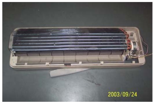
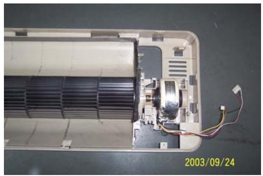
Indoor Unit
| Operating step | Photo |
| 1. To remove the panel and connecting wire cover.
·Take off the screws of the connecting wire cover and remove the cover.
·Then remove the panel. | 2003/09/24 |
| 2. To remove the air filter. | 2003/09/24 |
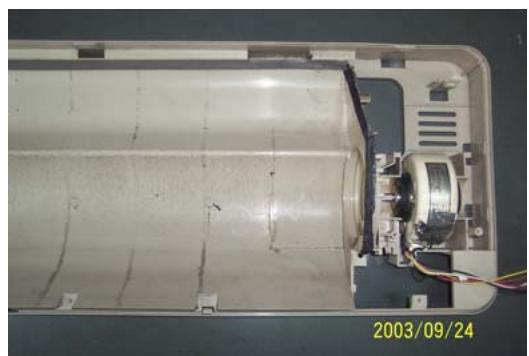
| 3. To remove the inter frame assembly
·Take off three screws of inter frame assembly
·Then take off the inter frame assembly | 2003/09/24 |
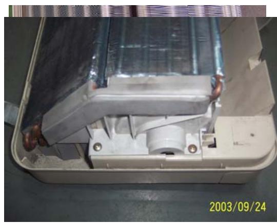
| 4. To remove the electric control box
·Take off one screw
·Loose one obverse clip
·Remove the electric control box | 2003/09/24 |
- To remove the water-collecting plate assembly
Loose three obverse clips
Take off the electric control box
- To remove the evaporator assembly
Take off one screws of right locating cover and two screws of left locating cover
- Remove the pipe strap
- Remove the evaporator assembly

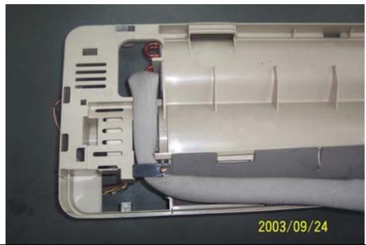
- To remove the through-flow fan
Take off the screws of though-flow fan
- Remove the though-flow fan
- To remove the motor
Take off three screws of right locating cover
- Remove the motor

Outdoor Unit
| Operating step | Photo |
| 1. To remove the top cover assembly
• Take off six screws of top cover | 2003/09/24 |
| 2003/09/24 |
| 2. To remove the panel assembly
• Loose screws of panel assembly
• Take off panel | 2003/09/24 |
| 3. To remove the right plate assembly
• Loose nine screws of left plate assembly
• Take off right plate | 2003/09/24 |
Chapter 7 Brief introduction of installation
The installation of air-conditioner should meet with the "Installation Instruction".
The machine must be installed correctly by professional technicians according to the "Installation Instruction".
Guide to customer
- The customer should provide a suitable power supply source, its voltage should be in the range of 90 - 110% of its rated voltage.
- The power supply circuit should have MCB leakage protection. The capacity should be more than 1.5 times of the maximum current.
- Must use independent circuit and suitable grounding socket matching with the plug of air-conditioner.
- The wiring must be installed by qualified electrician according to the electrical safety requirements.
- The air-conditioner must be well grounded, the switch of the main power of air-conditioner must be reliably grounded.
The power supply wire, must be changed by qualified electrician.
Installation Instruction
Installation order:

Testing
Selection of the installation position
Indoor Unit
There is no heating and steaming nearby.
No obstacles for installation from nearby.
- Keep good air circulation.
- Convenient to adopt measures to noises.
Don't install them near the doorway.
Make sure to have the distance specified in the picture between the wall, furniture and other obstacles.
2 meters high above the floor.

source
position
reduce
ceiling,
Outdoor Unit
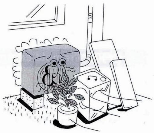
- In case that you put up a canopy to protect it from rains and sunrays, pay attention not to cause any obstacles for the heating dispersion for the condenser.
- Don't keep animals or plants near the installation location for the hot air from the outdoor unit will affect them.
- Make sure to have the distance specified in the picture between ceiling, wall, furniture and other obstacles.
- Stay away from heating source and inflammable air.
- The installation base and supporting frame should be strong and secure. The machine should be at a level surface.
Installation of the Outdoor Unit
The outdoor unit must be firmly fixed avoid falling in strong wind.
Install on the cement base as in the drawing.
- If it is installed at seaside or at a place

to
high
above the ground and with strong wind, the AC should be installed against the wall to ensure the normal operation of the fan and the blocking plate should be used.
- If it is an overhanging installation, the structure of the mounting wall should be made of solid, cement or materials with equivalent strength, and of sufficient support capacity. Otherwise, measures such as reinforcement, support or vibration damping should be adopted.
Installation of the Indoor Unit
- First make changes to wall and make sure that is hard and secure. Using four "+" type screws to fasten the installation board onto the wall. Keep it level in horizontal direction and perpendicular in vertical direction. Otherwise it might cause water drips when air-conditioner is running in cooling operation.
- Drill 70mm diameter pipe hole at the left lower or right lower side of the installation board. The hole shall slant outward slightly.
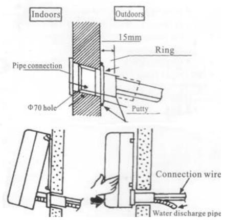
- Hang the indoor unit to the board and make sure the machine is in the middle of the board.
- Push the machine towards the left lower and right lower side of the installation board until the hangers enter tightly into the grooves (it produces "click" sound)
Check the water discharge
- Take off the frame from the unit cover.
Take off the front frame for maintenance according to the

following steps:
- As shown in the picture on the right, take off two covers from the front frame and then unfasten two fixture screws.
Pull the front frame towards yourself and take it off.
To put the front frame back, reverse the steps.
You should check whether the front frame is firmly fixed into the fixture groove on the top.
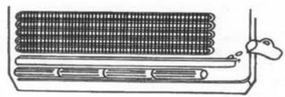
2. Check the water discharge
Pour a cup of water into groove.
- Check whether the water flow through the water discharge hole.
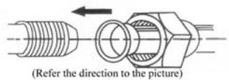
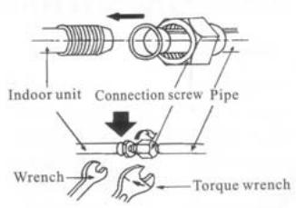
Pipe Connection
- Connect the pipe to the unit: point to the pipe and fasten the connection screw at hand and then by wrench until it is fastened. The fastening direction is the picture.
- Pointing towards the center of pipe, fasten with strength.
Wrench the screw in the end until you hear
center of first by tightly shown in

the screw
the
The fixing of pipe
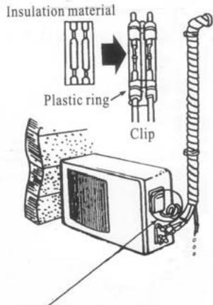
- Wrap up all pipe, water discharge and connection wire from top to below.
- Cover the connection parts with insulation material and fix them with plastic rings.
- Wrap up the pipes with tape alongside and fix them to the wall with clips.
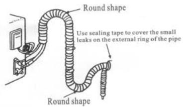
Round in this shape to prevent water entering the electrical parts.
two
the wall These
steps are usually adopted when outdoor unit is installed below the indoor unit.
-
In case that you want to have additional water discharge pipe, the end of pipe should be within certain distance from the floor (to prevent water from draining back into the pipe). Fix it onto the wall so it won't be swayed by wind.
-
Wrap the pipes and connection wire below to top.
-
Wrap up the pipes that are rounded way shown in the picture so it can water from entering the room.
Use clips or other fixture to fasten to the walls.
well from
up in the prevent
the pipes
Expelling the air in the pipes and the indoor unit
Expelling the air: humid air in the refrigerating system might cause trouble of compressor.
Take off the cover from the stop and T-branch valve.
Take off the auxiliary cover from T-branch valve.
-
Turn the stop valve rod anti-clock an angle of 90 degree, keep it open seconds and close the valve.
-
Check whether there is air leakage connection parts of pipes.
-
Push the top rod of T-branch valve hexagon wrench to expel air.
Repeat the third and fifth steps.
-
Open the stop and T-branch valve with a hexagon wrench to make the unit operate.
-
No leakage is allowed, please check all the piping connection parts. You must test the leakage, generally, it can be tested by soap water.

valve
the
wise to
for 8
at all
by
Electrical connection
-
Unscrew the screw, take off the control panel cover from the unit.
-
Cooling type: connect the wire to the related connection point on the panel and connect the signal connection plug.
Remarks: yellow and green cord should be connected to connection point with mark.
- Fasten the fixture of wire to control panel.
- Screw up the control panel cover to its original place.

Test running
Connect the wire to independent power source socket.
Preparation of remote control.
Run the air-conditioner in cooling operation mode for 30 minutes or longer.
- Performance evaluation
Test the out and in air temperature.
Make sure that the temperature difference between the out and in air is greater than 8^ .

Discharged air
Items of attention
Fix the machine firmly, otherwise it will produce noise and vibration.
Install the outdoor unit where it will not disturb your neighbor.
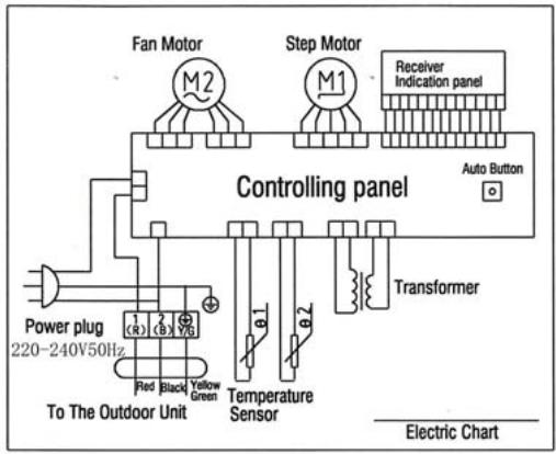
Electrical connection diagram:
COOL SERIES

HEAT PUMP
Indoor unit electric connection diagram
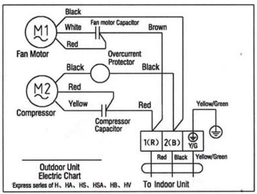
COOL SERIES
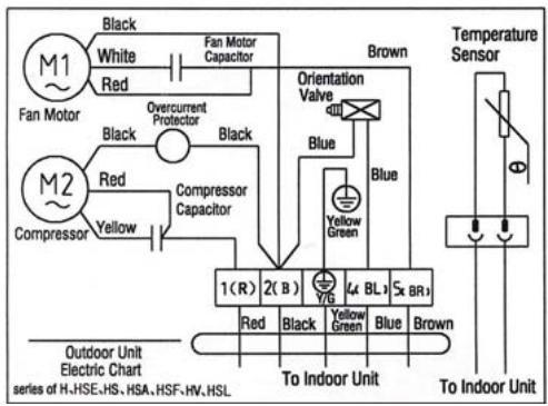
HEAT PUMP
Outdoor unit electric connection diagram
Chapter 8 Fault Analysis of the Product Available and
Typical Examples
1 Procedure of deciding the faults
Before maintaining the air conditioner, firstly you should know the phenomena of the faults, decide the location of the faults, analyze the reason the faults occur, and then search for ways to solve the faults. The detailed procedures are: Look, Listen, Touch, Measure, Analyze
Look: Observe air conditioner's running. I.e., vibration; condensation on evaporator; leakage; electrical and mechanical connection, etc.
Listen: Listen to kinds of sounds of the running air conditioner. Identify the abnormal noise from the sounds.
Touch: Touch the key position and position faulty. Touch the temp of air circulation to decide the heating or cooling effect; as far to abnormal sound, besides adopt "listen", you should touch the frame, the pipe of the air conditioner to feel the vibration. Touch the easily heated parts, i.e. compressor, motor, touch them to feel the temp.(Warning: High temp).
Measure: Measure the parameters of the air conditioner and relevant parts by some instruments. Usually used instruments: amperometer, voltmeter multimeter thermometer, etc, i.e., Use multimeter to test whether the capacitor is open, the insulation of the wire and the parameters of other electrical parts; use the thermometer to measure temp of airflow.
Analyze: Analyze the above results, decide the reason and location
of faults, and seek the solutions.
2 Types of Normal Faults
The type of faults is various. The normal faults can come down to six types: leaks, block, open circuit, burnt, lock, scrape.
Leak Mainly is leakage of R407C from cooling pipe system and parts; leakage of condensation water from indoor units; electrical leakage from electrical system and wires.
Block Mainly is block of the pipe system, block of capillary, block of strainer or valve.
Open Circuit Mainly is open circuit of electrical circuit, include: fuse blowing out, connectors broke.
Burnt Mainly is burnout of fan motor, of compressor, of capacitor, of transformer.
Lock Mainly is lock of compressor, four-way valve.
Scrape Mainly is scrape of indoor/outdoor fan and nearby parts, and sound abnormally.
3 Examples
3.1 Leakage and seepage of indoor unit
| Reason | Check to be made | Proposed remedy |
| Improper installation.
Indoor drain position is lower than outdoor or slanting installation of indoor unit | Observe if the condensation water drain out, if the indoor unit is declining | Level the indoor unit and adjust the height |
| Water collecting plate is blocked | Check if the plate is blocked | Remove the matters block the plate |
| Water collecting plate or drain pipe is cracked | Check the location, ensure if it is cracked | Replace the plate or pipe |
| Loosen wrap belt, heat-preservation layer is bad or layer behind indoor units is bad | Connecting pipe bleed the water, condensation water exists behind the indoor unit, the wall is wet and turn colors | Rewrap the connecting pipe, add new heat-preservation layer |
| High ambient relative humidity, low temp/speed of air flow | Water is blow out from air outlet, or water drips from the outlet. Lower speed of air flow | Suggest set the units to dehumidifying mode at high speed of air flow, to lower relative humidity; if the high speed is still felt lower, the fan motor must be checked |
3.2 Poor cooling or heating effect
| Reason | Check to be made | Proposed remedy |
| The cooling/heating load of the room is heavy or the room is not closed perfectly | Calculate the area of the room, check the close of the room | Enlarge the capacity of the units, improve the leakproofness of the room |
| Insufficient refrigerant R407C | Measure the operating current | Add R407C welding the leaked point |
| Too much R407C | Air intake temp is too low, condensation water on air intake pipe is too much, temp of discharge is too high | Discharge a little R407C |
| Effect of heat exchange is too poor | Dust on outdoor condenser and indoor filter is too much | Cleanup filter and condenser |
| Some of the windings of motor fan is short-circuit, so cause speed decline | Speed of indoor/outdoor fan is too low, air circulation is small | Repair or replace motor |
| Running condition is too bad | Check if the installation is proper; outdoor temp is too high when heating | Improve the condition, use auxiliary heating |
| Convexity exists in compressor or valve or lock of compressor | No high-low pressure difference, no clear temp difference in air intake inlet or discharge outlet of compressor | Replace compressor or valve |
| Openness of check valve is too small or the system partly or completely blocked | Check the openness; partly frost on outdoor pipe system | Open the valve; use high pressure N2to clean out the block |
3.3 Big noise or abnormal sound
| Reason | Check to be made | Proposed remedy |
| Foreign matters in wind guide or impeller fan | Check if they are | Clear away |
| Fan is distorted or in bad balance | Check them | Replace indoor/outdoor fan |
| Improper location of fan, so fan touches the housing | Open the unit or move the fan manually, find the location | Adjust the position |
| Bearing of the fan is sluggish or destroyed | Check the bearing | Replace the bearing |
| Connecting pipe vibrates due to improper installation, or touch the lower frame | Check the connecting pipe | Tidy up the pipes, eliminate the noise source |
| Outdoor pipes touches | Check the vibration of the pipes, check if them touch | Tidy up the pipes |
| Abrasion of the parts of compressor | Check if the sound of compressor is normal | Replace the compressor |
3.4 Frequently switch on/off of the compressor
| Reason | Check to be made | Proposed remedy |
| Running voltage is too low | Measure the voltage | Add measures of voltage stabilization |
| Discharge temp is too high caused by insufficient of R407C, compressor is protected by overheat | Check condensation of air intake pipe or measure if operating current is lower than rated current | Check leakage point, welding or add R407C |
| Temp sensor is too close to evaporator or moved | Check the position of sensor | Adjust the position or replace the sensor |
| Air inlet/outlet of heat exchange is blocked or low speed of fan motor; indoor air filter is too dirty or blocked | Check indoor/outdoor heat exchange, speed of motor, air inlet/outlet | Cleanup the filter, remove the obstacle |
| Too much R407C | Too much condensation water on air intake pipe, high operating current | Discharge a little R407C |
| Bad insulation of compressor, high operating current, overcurrent proof | Check start or operating current | Replace compressor |
| Improper temp set | Check actual ambient temp | Reset |
3.5 Promptly protected by halt after compressor starts
| Reason | Check to be made | Proposed Remedy |
| Insufficient R407C | Little or no condensation water on air intake pipe, operating current is lower than rated current | Add R407C |
| Mixed with air in the system, vacuum is not good | Power varies when running | Vacuumize the system, recharge R407C |
| Blocked caused by water or impurity | Operating current is lower than rated current, part of the unit frosts heavily | use high pressure N2to clean out the block, revacuumize and recharge R407C |
| Damaged compressor, high start current | Check the windings and insulation of compressor and if it is locked | Replace the compressor |
3.6 The units blow out cool air when in heating mode
| Reason | Check to be made | Proposed Remedy |
| Four-way valve doesn’t work | Listen to the units if there is sounds of valve’s working when heating or cooling | Replace the valve |
| Faults of control interruptor or other relevant circuits of the valve | Check the circuit | Repair or replace the control board |
| Insufficient R407C causes the insufficient heating capacity | Little condensation water on outdoor air intake pipe, low operating current | Add R407C |
| Connexity of compressor | Same temp of air intake inlet and discharge outlet of the compressor, no condensation in air intake inlet | Replace the compressor |
3.7 The units doesn't work
| Reason | Check to be made | Proposed Remedy |
| Bad connection of the power plugs, or no power plug | Check the socket | Repair or replace |
| Outdoor fuse or indoor fuse is burnt | Check if the fuse is good | Replace the fuse |
| Low voltage | Measure the voltage | Heighten the voltage of the power supply system |
| Wrong indoor temp set | Measure actual indoor temp, compare to the set temp(in cooling set temp should be lower than the actual, in heating, is higher) | Reset the temp |
| Wrong running mode of indoor units set | Check if running mode of two indoor units is the same( it is not available if one is heating and another is cooling | Reset |
3.8 Cannot receive the remote control signal
| Reason | Check to be made | Proposed Remedy |
| Damaged remote control or low battery | Check if the indication is normal | Replace the remote control or battery |
| Short-circuit of connections of main control board to switch board | Check the board | Replace the components |
| Running mode of two indoor units is not the same | Check if one is heating and another is cooling | Reset |
| Indoor units are in test mode | Open the air intake grill to see the running mode | Adjust test mode to remote control mode |
Remarks The above mentioned "faults" are the faults possibly occur, we will continue to collect the faults and analysis.
CONTENTS
Chapter 1 photos and Features of products
Chapter 2 Operating Principle
Chapter 3 operation details
Chapter 4 Exploded Views of the Production
Chapter 5 Main Technical Data
Chapter 6 Dismantling Procedure
Chapter 7 Brief introduction of installation
Chapter 8 Fault Analysis of the Product Available
Chapter 1 photos and Features of products
Features of outlook and construction
ASW-H12A4/HSAR
ASW-12A4/HSAR Deep × width × high 176× 890× 296
ASW-H12A4/HSR
ASW-12A4/HSR
Deep × width × high 176x890x296

Deep × width × high 260× 760× 540
All types
All types
Operation interface
Inner operation interface of Type HSAR
Inner operation interface of Type HSR

Emergency operation button of indoor types:

1) When the air-conditioner works with the absence of remote control, it will stop
working by pressing the compulsory button and it will resume working by pressing the compulsory button once again.
2) When remote control is useless, you can adopt the compulsory operation by which the air conditioner will go into automatic operation mode.
The operation interface of remote control:

Features of products
- Fashionable appearance
- Compact Design
3.7 Hours of Sleep Mode Operation
-
Economy Mode to Reduce Electrical Power Consumption
-
Clean breath efficient biological antibacterial filter gauze made from green plant elite refined by using international leading technology, with the function of filtering and suppressing bacteria, and able to absorb and kill various pathogens and harmful gases efficiently for a long period, prevent secondary pollution caused due to microorganism spreading, and ensure the health of your family
- R407c cold medium is applied, environment-friendly, and avoid damages to ozonosphere
- International famous-brand Toshiba Hitachi and Matsushita compressors are applied
Chapter 2 Operating Principle
. Cooling
After the power supply is switched on, the machine is set to COOL mode. With the compressor being operated, the low-temperature and low-pressure refrigerant vapor is sucked into the compressor where it is turned into high-temperature and high-pressure gas. Then it is cooled down in the outdoor heat exchanger by the air and becomes liquid. After being throttled by the capillary, the refrigerant liquid comes into the indoor unit and then it evaporates in the indoor heat, exchanger,

absorbing heat and reducing the room temperature. The evaporated refrigerant vapor returns to the outdoor unit and is again sucked into the compressor, completing the cycle. With the refrigerant cycling being kept on, the objective of lowering the room temperature is fulfilled.
. Heating
After the power supply is switched on, the machine is set to HEAT mode and the coil of the electromagnetic four-way valve is energized. After the compressor starts to operate, the high-temperature and high-pressure refrigerant gas first comes into the heat exchanger of the indoor unit, where it is cooled, releases heat and increases the room temperature. The cooled high-pressure refrigerant is then throttle1d in the outdoor unit and returns to the compressor after evaporation. With such cycles being maintained, the objective of increasing the room temperature is fulfilled.
Operation Hints
Adjust room temperature properly. Set the temperature 1^ higher than actually desired. Approximately 10% of electricity costs can be saved.
Clean the air filter regularly. Blockage in the air filter reduces the airflow and lowers the cooling. Clean at least once every 2 weeks. Otherwise, 6% of electricity cost will be wasted.


Prevent waste with the Timer. Use Timer when sleeping or going out to save electricity cost.
Do not block the air outlet vents at outdoor unit. Otherwise, it will lower the cooling performance.

Make sure that the doors and windows are shut. Otherwise, cooling performance will be reduced and electricity cost is wasted.
Keep blinds or curtains closed. Do not let sunshine enter the room directly. 5% of electricity cost can be saved.


Proper airflow direction adjustment. Set the airflow direction louvers horizontal for Cooling Operation. Operation result will be better.
Use insulating material for better performance. Use insulating material during construction or renovations. It will save electricity cost.
Chapter 3 operation details
1. Overall
1.1 Protection of compressor
Whatever operation modes the air-conditioner is under, there will always be 3 minutes' time-delay protection unless it is on for the first time. When the compressor is switched on, it can not be shut down within 3 minutes (except under the modes of heating or defrosting) unless it is powered off or its operation mode is changed.
1.2 The operation indicator will turn light when the air conditioner is powered on.
1.3 The buzzer will sound immediately after the controlling device receives a correct and effective signal sent by the remote control.
1.4 Timing function can be applicable to all operation modes while sleep function can only be applicable to the modes of refrigeration and heating.
2. Automatic operation mode
2.1 When the air conditioner works, it can detect the indoor temperature automatically whereby its operation mode can be selected: refrigeration, heating or dehumidification.
2.2 When the indoor temperature reaches more than 27, the air conditioner will operate under the mode of refrigeration.
2.3 When the indoor temperature reaches between 20 and 27 the air
conditioner will work under the mode of dehumidification (always mute).
2.4 When the indoor temperature reaches less than 20, the air conditioner will work under the mode of heating.
2.5 Under this mode, the air conditioner will operate in the respect of blowing rate as set and its pendulum leaves will work according to the requirements of automatic ventilation door.
2.6 Once the operation mode is selected, it will not be able to be changed. When the air conditioner is shut down and then restarted, the operation mode will be selected once again based on the variation of indoor temperature.
2.7 After the operation indicator has been flickering for 20 seconds, it will turn light steadily (i.e. the determination of operation mode will start in 20 seconds.)
2.8 This mode has timing function, does not have sleep function.
2.9 Under this operation mode, the temperature can be set and adjusted by remote control.
3. Refrigeration mode
3.1 Under the refrigeration mode, the range of temperature set by remote control is between 16 and 32.
3.2 Shut-down of four-way valve;
3.3 The condition on which the compressor starts is that the indoor
temperature reaches more than the temperature set plus 1 while the condition on which the compressor shuts down is that the indoor temperature reaches less than the temperature set minus 1 .And when the indoor temperature is equal to that set, the original operation mode will be kept.
3.4 Under the mode of refrigeration, the function of preventing indoor coiled pipe from being frozen will be effective.
3.5 The indoor wind speed will be as set. And the pendulum leaves will work according to the instructions sent by remote control.
4. Dehumidification operation
4.1 The temperature range set and controlled is between 16 and 32 . The temperature will be set by remote control.
4.2 The four-way valve is shut down.
4.3 The wind speed gear-changes to "mute". And the pendulum leaves works according to the instructions sent by remote control;
4.4 The function of preventing indoor coiled pipe from being frozen is effective.
4.5 When the indoor temperature reaches less than 16, the function of dehumidification is out of use.
4.6 When the indoor temperature reaches more than 16, the compressor will be switched on and work intermittently. The time when the compressor shuts down depends on T ring and T ring-T set.
When the compressor is shut down, the outdoor fan and indoor fan will stop working.
When T ring ≥ 23
T set < T ring-1, the compressor will be working for 8 minutes and then stopping for 3 minutes in cycles.
T set≥T ring-1, the compressor will be working for 3 minutes and then stopping for 6 minutes in cycles.
And when T ring < 23
T set ≤ T ring-1, the compressor will be working for 3 minutes and then stopping for 4 minutes in cycles.
T set >T ring-1, the compressor will be working for 3 minutes and then stopping for 6 minutes in cycles.
5. Function of ventilation control
5.1 Under the mode of ventilation, the outdoor fan assembly will always be shut down.
5.2 The indoor fan will operate as set in the respect of air quantity without the gear- change of "high power".
5.3 The pendulum leaves will work according to the instructions sent by remote control.
6. Heating function
6.1 Under the mode of heating, the temperature range set is between 16 and 32. And the temperature will be set by remote control.
6.2 When the air conditioner is powered on, the outdoor fan, four- way valve and compressor will start at the same time while when it is shut down, the outdoor fan and compressor will be shut down at the same time and so will the four- way valve after 2 minutes' delay.
6.3 Under the mode of heating, the compressor can not be shut down within 3 minutes after it is powered on unless the operation mode is changed or the air conditioner is turned off.
6.4 There is a 3-temperature compensating function. The temperature measured at the in-blow vent minus 3 automatically can be regarded as that compared with the temperature set (This function does not exist under other circumstances).
6.5 According to the temperature set, the condition upon which the compressor will be switched on is indoor temperature ≤ temperature set-1 While the condition upon which it will be switched off is indoor temperature is indoor temperature ≥ temperature + 1 . When the indoor temperature is equal to that set, the original operation mode will be kept.
6.6 Indoor fan control:
6.6.1 Heating operation and prevention of cold wind
When the compressor works:
- During the rising process of the temperature of coiled pipe, the indoor fan will not start if the temperature of the coiled
pipes is less than 25 .
-
When the temperature of coiled pipe reaches less than 35 But more than 25, The indoor fan will work under the mode of " mute". If the temperature of coiled pipe ascends to 25 and then descends, it will stop working only when the temperature is lowered to 22.
-
When the temperature of coiled pipe reaches more than 35, the indoor fan will operate as set in the respect of wind speed. If the temperature of coiled pipe ascends to 35 And then descends, it will enter into the operation mode of " mute" only when the temperature is lowered to 30 .
6.6.2 Afterheat-blowing function:
6.6.2.1 When the compressor stop working:
- When the temperature of coiled pipe is more than 35, the indoor fan will operate as set in respect of wind speed.
- When the temperature of coiled pipe is more than 25 , but lessthan 35 , The indoor fan will operate under the mode of “ mute"
- When the temperature of coiled pipe is less than 25, the indoor fan will stop working.
6.6.2.2 The afterheat-blowing function when the air conditioner is just shut down: If the temperature of indoor coiled pipe reaches more than 30 , The indoor fan will operate under the mode of “ mute”; If
it lowers to less than 30 , the indoor fan will be shut down; And the
time when the afterheat blows will last less than 40 seconds after
the indoor fan is turned off.
6.7 Defrosting operation:
6.7.1 The conditions upon which the outdoor sensor goes into operation are
as below:
-
Under the circumstance of heating, if T external coiled pipe is at the temperature of less than -6 which lasts 2 minutes and the accumulated working time of compressor reaches more than 50 minutes (if there is any power cut-off or shut-down by remote control, the accumulated working time of compressor shall be re-calculated), the defrosting interval will be more than 50 minutes and the compressor will be working 5 minutes continually.
-
If there is any damage to the external coiled pipe, the accumulated working time of compressor will reach 50 minutes (if there is any power cut-off, shut-down by remote control or defrosting, the accumulated working time of compressor shall be re-calculated) and the defrosting operation will last 10 minutes.
6.7.2 Once one of the following conditions is satisfied, the defrosting will
end:
- The temperature of T external coiled pipe is more than 12 .
- Defrosting duration is more than 12 minutes.
6.7.3 The requirements of defrosting operation:
-
Sleep indicator flickers at the speed of 1 time per second
-
When defrosting operation starts, the compressor and indoor fan will stop working while outdoor fan and four-way valve will continue to work.
-
The four-way valve and outdoor fan will stop operating in 30 seconds.
-
15 seconds after that, the compressor starts and goes into defrosting operation.
-
After the defrosting ends, the compressor stops working. And the four-way valve and outdoor fan begins to work in 20 seconds.
-
20 seconds after that, the compressor starts and goes into heating operation. And the indoor fan enters into the prevention mode of cold wind.
6.8 Auxiliary electric heating function
6.8.1 Only if the following conditions are satisfied under the heating operation, can the auxiliary electric heating go into operation automatically.
a. The compressor works for 4 minutes by heating pump
b. Indoor temperature is less than 22 ;
c. The temperature set-indoor temperature is more than 3 ;
d. Indoor fan goes into operation;
e. Indoor coiled pipe temperature is less than 48
6.8.2 Once one of the following conditions is satisfied, auxiliary electric heating operation will end:
a. Indoor temperature is more than 22 .
b. The temperature set -indoor temperature is less than 2 .
c. When Indoor coiled pipe temperature is more than 52 , theelectric heating operation will end.
d. Indoor temperature sensor becomes abnormal.
6.8.3 If compressor or indoor fan stops working, the electric heating will stop operating as well.
6.8.4 During the operation of compressor, if the auxiliary electric heating stops working, it can be restarted only in 1 minute.
7. Sleep operation
7.1 When the air conditioner enters into the mode of sleep, the indoor wind speed will turn into the air quantity of "mute".
7.2 When the sleep operation goes under the mode of refrigeration, the temperature set rises by 1 automatically every one hour. And the air conditioner will be powered off after sleep mode has worked for 7 hours.

7.3 When the sleep operation goes under the mode of heating, the temperature set drops by 2 automatically every one hour. And the air conditioner will be powered off after sleep mode has worked for 7 hours.

7.4 When the button of mode selection is pressed down, the function of sleep will be cancelled.
7.5 Sleep operation is effective under the modes of refrigeration and heating. When sleep button is pressed down, the sleep operation can begin or end.
7.6 Sleep function does not exist under the automatic mode, the situation of dehumidification or the circumstance of ventilation.
8. Timing operation
8.1 When timing is set, timing indicator will turn light.
8.2 The time set by timing is 12 hours at most. The timing unit is 1 hour. Even if the operation mode is changed, the timing function will still work.
8.3 Power-off at a fixed time
The power-off at a fixed time can be set only if the air conditioner is on. And it continues to work though the power-off at a fixed time has been already set. When it comes to the fixed time, the indoor and outdoor fans will be shut down.
8.4 Power-on at a fixed time
The power-on at a fixed time can be set only if the air conditioner is on. And it continues to be off though the power-on at a fixed time has been already set. When it comes to the fixed time, the indoor and outdoor fans will start to operate.
9. Emergency switch
When the soft-touch switch is pressed, the air conditioner will be powered on and the operation indicator will flicker (1 time per second). And it goes into the mode of automatic operation in 20 seconds. When the soft-touch is pressed once again, it will be powered off. When the air conditioner goes under the mode of automatic operation, the air door will assume the appearance of automatic air door. Under the mode of heating or refrigeration, the temperature set will be 24 and the wind speed will turn that under the "high power" mode. Under the dehumidification operation, the temperature set will be T ring-2 and the air conditioner can work upon the instructions sent by remote control.
10. Overload control and various protection functions:
10.1 Temperature control (overheat protection).
10.1.1 This function can only be applied to the mode of heating, not others.
10.1.2 When the temperature of indoor coiled pipe reaches more than 57, outdoor fan will stop working.
10.1.3 When the temperature of indoor coiled pipe drops to less than 52, outdoor fan will resume to operate normally.
10.2 Temperature cut-off control function (overheat protection)
10.2.1 This function can only be applied to the mode of heating, not others.
10.2.2 When the temperature of indoor coiled pipe reaches more than 64 which lasts more than 10 seconds, the compressor and outdoor fan will all stop working.
10.2.3 After 3 minutes' shut-down, the compressor will resume to operate if the temperature of indoor coiled pipe drops to less than 52.
10.3 Function of preventing indoor coiled pipe from being frozen (supercooling protection).
10.3.1 This function can only be applied to the operation mode of refrigeration or dehumidification, not others.
10.3.2 When the temperature of indoor coiled pipe drops to -2
which lasts more than 2 minutes, the compressor will stop operating and the indoor fan will go by air quantity set.
10.3.3 When the compressor stops working, it can only be restarted only if the temperature of indoor coiled pipe rises to more than 7 or the power-off of the compressor lasts more than 6 minutes.
10.4 Protection function of short or open circuit of temperature senor
10.4.1 Powered on, when it is detected that the T ring signal sent by indoor environment temperature senor is abnormal, the air conditioner will work under the mode of heating and will not be powered off if the signal received from remote control is “heating” or it will work under the mode of refrigeration and will not be powered off if the signal received from remote control is “refrigeration” or it will work for 8 minutes and then stop for 3 minutes with the wind speed of “mute cycle dehumidification” if the signal received from remote control is “dehumidification”. Besides, the signal of automatic mode sent by remote control will not be effective, nor will the signal of automatic button power-on and the related breakdown can be indicated at the same time.
10.4.2 When it is detected that the T internal coiled pipe signal sent by indoor coiled pipe temperature sensor is abnormal, the freezing-proof, cold-wind-proof and overheat-proof functions
will be screened. Under the mode of heating, when the compressor is powered on, indoor fan will be started after 30 seconds' delay with the wind speed as set while when compressor is powered off, indoor fan will be turned off after 30 seconds' delay and the related breakdown can be indicated at the same time.
10.4.3 When it is detected that the T external coiled pipe signal sent by outdoor coiled pipe temperature sensor is abnormal, the air conditioner will work for 50 minutes, defrost for 10 minutes and heat in cycles if the signal received from remote control is "heating" and the related breakdown can be indicated at the same time while the air conditioner will not be powered off and will operate normally if the signal received from remote control is heating or defrosting or ventilation and the related breakdown can be indicated at the same time.
10.5 disposal of indoor PG electric motor abnormality
When indoor PG electric motor is loaded with voltage, the indoor fan will operate under the mode of "weak wind" automatically if the pulse signal feed backed by the indoor electric motor is not detected within 12 seconds. If the feedback signal detected is normal, the indoor fan will resume the turning speed set and the related breakdown indication will be disappear.
10.6 Function of charatron display
When the controller is normal, there will be no charatron display under the circumstance of power-off. When air conditioner is powered on, the charatron will display room temperature under the normal situation. If the temperature set is changed, the charatron will show the temperature set which sparkles at the rate of 1 time per second. Then it will display room temperature once again in 5 seconds. The display range of room temperature is 0 79 .
11. Function of breakdown indication
HS, HSA series (charatron); HV (VFD display)
| Breakdown cause | Display way | Display priority class |
| PG feedback abnormality | E4 | 1 |
| T ring abnormality | E1 | 2 |
| T internal coiled pipe abnormality | E3 | 3 |
| T external coiled pipe abnormality | E2 | 4 |
12. Adjustment function of air door direction by pendulum leaves
12.1 When the air conditioner is powered on for the first time, the pendulum leaves will move to the direction of full-opening and then to the direction of full-closing wherever they are placed.
12.2 When the air conditioner is powered off, the pendulum leaves will move up to "close" position immediately wherever they are placed after the fan comes to an end.
12.3 Under the mode of refrigeration, the pendulum leaves will first move to the full-opening position and then move to the horizontal position and at last move under the mode set while under the mode of heating, they will first move to the full-opening position and then backswing by 5 and at last work under the mode set (for details, please see the following diagram).
12.4 Pendulum wind: automatic air door and manual air door will be controlled by one button.
12.5 When the pendulum leaves move from full-opening position to full-closing position at the time of power-on or from starting position to full-closing position at the time of power-off, the speed will be 20 per second while the speed under the instruction situation will be 5 per second.
Swing angle under the mode of refrigeration: BD is 35 ± 2
Swing angle under the mode of heating: FC is 40 ± 2
Backswing angle under the mode of heating: EF is 5
13. Self-checking function of controller
After the automatic button is pressed, the air conditioner will be powered on and enter into the process of self-checking:
Buzzer sounds two times operation indicator turns on timing indicator turns on compressor acts four-way valve acts outdoor fan acts electric heating acts indoor fan acts buzzer sounds one time which means that air conditioner goes into the state of order-waiting and the self-checking comes to an end.
14. Remote control
Name and functions of the button on the remote control
(1) Timing ON/OFF button: set the timing mode. After each pressing, the mode will be changed. It shows in the following display.
(2) Sleeping button: which enables you to start the automatic operation in sleeping mode and stops by pressing on it again.
(3) Selection button for operation mode: which enables you to select different operation modes, after each pressing, the operation mode will be changed. It shows in the following display.

Remarks: Only cool type remote control has no heat mode
(4) Wind direction adjusting button: press the button, the horizontal airflow direction plate can adjust automatically. When you have the desired wind direction, please press it again, the airflow direction plate will maintain the same position.
(5) Fan speed selection button: you can select fan speed from "Power", "High", "Low", and "Mute".
(6) ON/OFF button: you can start the air-conditioner by pressing this button and stop its operation by pressing it again.
(7) Setting button▲: Press the button, the setting temperature or timer
will increase.
(8) Setting button : Press the button, the setting temperature or timer will decrease.
Display

(1) Mode display: press the MODE button, it shows the current operation mode. You can select “Automatic”, “Cool”, “Dry”, and “Fan” “heat” operation mode. (cold wind type has no heating mode)
(2) Sending display: when the remote control sends correct and effective signal each time, the sign displays intermittently each time.
(3) Fan speed display: press the "WIND" button, the fan speed will display. You can select fan speed from "Power", "High", "Low", and "Mute".
(4) Number display: which displays the setting temperature, in the circulation operation mode, the temperature number does not display.
(5)Timer ON/OFF display: which displays the timer states, “the timer ON” and “the timer OFF” do not set at the same time.
Remark: For illustration, all display items are listed here. When the mode operates, the relevant items display on the remote control.
Application
Fix batteries
(1) Slide open the cover according the direction indicated by arrowhead.
(2). Put into two AAA new batteries, position the batteries to right electric poles (+\& -) .
(3)Put back the cover.
Make sure to connect the wire to independent power source socket before you use the remote control.
Automatic operation mode
(1) Press the MODE button, select the automatic operation mode.
(2) Press the TEMP/TIME button, set the temperature, temperature can be set at 1^ difference range from 16 - 32^ .
(3) Press the WIND button, you can select fan speed from "Power", "High", "Low", "Mute".
(4) Press the ON/OFF button, the operation indicator is on, the air-conditioner starts to operate in the Automatic mode.
Press the button again, the air-conditioner stops.
Cooling/heating operation mode (cold wind type has no heating operating)
(1) Press the MODE button, select the Cooling operation mode.
(2) Press the TEMP/TIME button, set the temperature, temperature can be set at 1 difference range from 16 - 32^ C .
(3) Press the WIND button, you can select fan speed from "Power", "High", "Low", "Mute".
(4) Press the ON/OFF button, the operation indicator is on, the air-conditioner starts to operate in the Cooling mode. Press the button again, the air-conditioner stops.
Drying operation mode
(1) Press the MODE button, select the Drying operation mode.
(2) Press TEMP/TIME button, set the temperature, temperature can be set at 1^ difference range from 16 - 32^ .
(3) Press the ON/OFF button, the operation indicator is on, the air-conditioner starts to operate in the Drying mode. Press the button again, the air-conditioner stops.
Remark: In the drying operation mode, the fan speed is automatically set to "Mute".
Circulation operation mode
(1) Press the MODE button, select the Circulation operation mode.
(2) Press the WIND button, you can select fan speed from “High”, “Low”, “Mute”. In the circulation operation mode, you cannot select the speed of “Power”.
(3) Press the ON/OFF button, the operation indicator is on, the air-conditioner starts to operate in the Circulation mode. Press the button again, the air-conditioner stops.
Remark: In the circulation operation mode, you cannot set the temperature.
Timer setting
Set the "Timer ON" (it operates only when the air-conditioner shuts off.)
(1) Press the TIMER button, select the “Timer ON”, the remote control display “00 HOUR ON”; “ON” displays intermittently.
(2) Press the TEMP/TIME button, set the time. When “ON” stops intermittently, the “Timer ON” can be set.
Set the "Timer OFF" (it operates only when the air-conditioner is running.)
(1) Press the TIMER button, select the “Timer OFF”, the remote control display “00 HOUR OFF”; “OFF” displays intermittently at the same time.
(2) Press the TEMP/TIME button, set the time. When “OFF” stops intermittently, the “Timer OFF” can be set.
Remark: The remote control can only be set within 12 hour intervals.
Sleeping operation mode
(1) Press the SLEEP button, the sleeping indicator light of indoor unit flashes.
(2) After the setting of sleeping mode, the cooling operation enables the set temperature to increase 1^ after 1 hour and another 1^ automatically after another hour.
(3) After the setting of sleeping mode, the cooling operation enables the set temperature to increase 2 after 1 hour and another 2 automatically after another hour.
(4) The air-conditioner runs in sleeping mode for 7 hours and stop automatically.
Remark: 1. in sleeping mode the fan speed changes automatically to "Mute".
- Press the MODE button, WIND button or ON/OFF button, the
remote control clears sleeping mode away.
Attention:
Aimed the remote control at the receiver on the air-conditioner.
The remote control should be within 8 meters away from the receiver.
No obstacles between the remote control and receiver.
Don't drop or throw the remote control.
Don't put the remote control under the strong sunrays or heating facilities and other heating sources.
Use two AAA batteries, don't use rechargeable batteries.
Take the batteries out of remote control before stop using for long.
When the noise of transmitting signal can't be heard from indoor unit or the transmission symbol on the display screen doesn't flare, batteries need be replaced.
If reset phenomenon occurs on pressing the button of the remote control, power of the batteries is deficient and need to be replaced.
Chapter 5 Main Technical Data
| Type | ASW-H12A4/HSAR | ASW-12A4/HSAR |
| ASW-H12A4/HSR | ASW-12A4/HSR |
| Rated cooling capacity (W/BTU) | 3200/11000 | 3200/11000 |
| Rated heating capacity (W/BTU) | 3800/13000 | |
| Rated cooling current (A) | 5.4 | 5.2 |
| Rated heating current (A) | 5.5 | |
| Rated cooling power (W) | 1190 | 1150 |
| Rated heating power(W) | 1210 | |
| Air circulate (m3/h) | 500 | 500 |
| Power supply (V, Hz) | 220~240, 50 | 220~240, 50 |
| Refrigerant | R407C | R407C |
| Dehumidifying capacity(Kg/h) | 1.2 | 1.2 |
| EER | 2.7 | 2.8 |
| Noise dB(A) | Indoor unit | 39 | 39 |
| Outdoor unit | 51 | 51 |
| Dimensions(mm) | Indoor unit | 176×890×296 | 176×890×296 |
| Outdoor unit | 260×760×540 | 260×760×540 |
| PackingDimension(mm) | Indoor unit | 250×950×350 | 250×950×350 |
| Outdoor unit | 368×882×585 | 368×882×585 |
| Weight (kg) | Indoor(net/gross) | 10.5/12 | 10.5/12 |
| Outdoor(net/gross) | 38/40 | 37.5/39.5 |
| Applicable room area m2 | 12 20 | 12 20 |
NOTE: 1. Specifications are standard values calculated based on rated operation conditions, they will vary in different working condition
2. Our company has quick technical improvement. There will be no prior notice for any change of technical data. Please read the nameplate on the air conditioner
Chapter 6 Dismantling Procedure
Indoor Unit
| Operating step | Photo |
| 1. To remove the panel and connecting wire cover.
·Take off the screws of the connecting wire cover and remove the cover.
·Then remove the panel. | 2003/09/24 |
| 2. To remove the air filter. | 2003/09/24 |
- To remove the inter frame assembly
Take off three screws of inter frame assembly
Then take off the inter frame assembly
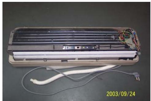
- To remove the electric control box
Take off one screw
Loose one obverse clip
- Remove the electric control box
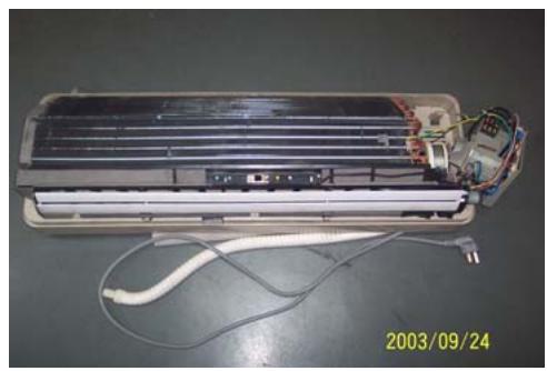
- To remove the water-collecting plate assembly
Loose three obverse clips
Take off the electric control box
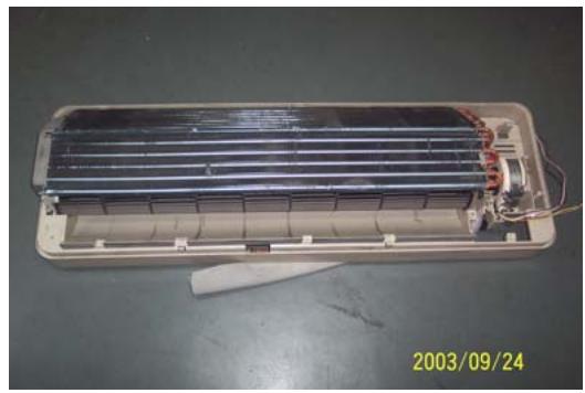
- To remove the evaporator assembly
Take off one screws of right locating cover and two screws of left locating cover
- Remove the pipe strap
- Remove the evaporator assembly
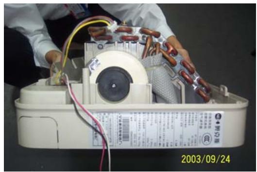
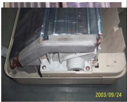
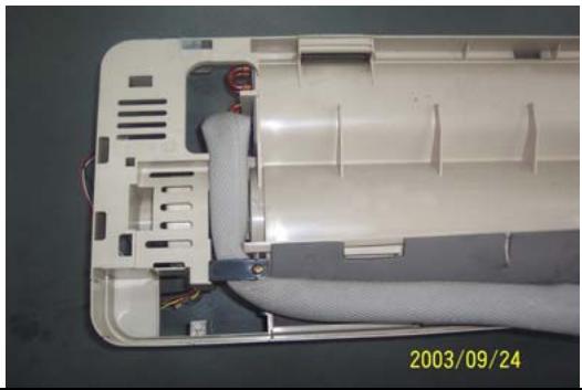
- To remove the through-flow fan
Take off the screws of though-flow fan
- Remove the though-flow fan
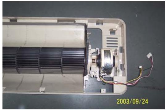

- To remove the motor
Take off three screws of right locating cover
- Remove the motor
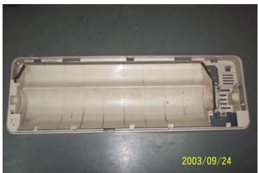
Outdoor Unit
| Operating step | Photo |
| 1. To remove the top cover assembly
• Take off six screws of top cover | 2003/09/24 |
| 2003/09/24 |
| 2. To remove the panel assembly
• Loose screws of panel assembly
• Take off panel | 2003/09/24 |
| 3. To remove the right plate assembly
• Loose nine screws of left plate assembly
• Take off right plate | 2003/09/24 |
Chapter 7 Brief introduction of installation
The installation of air-conditioner should meet with the "Installation Instruction".
The machine must be installed correctly by professional technicians according to the "Installation Instruction".
Guide to customer
- The customer should provide a suitable power supply source, its voltage should be in the range of 90 - 110% of its rated voltage.
- The power supply circuit should have MCB leakage protection. The capacity should be more than 1.5 times of the maximum current.
- Must use independent circuit and suitable grounding socket matching with the plug of air-conditioner.
- The wiring must be installed by qualified electrician according to the electrical safety requirements.
- The air-conditioner must be well grounded, the switch of the main power of air-conditioner must be reliably grounded.
The power supply wire, must be changed by qualified electrician.
Installation Instruction
Installation order:

Testing
Selection of the installation position
Indoor Unit
There is no heating and steaming nearby.
No obstacles for installation from nearby.
- Keep good air circulation.
- Convenient to adopt measures to noises.
Don't install them near the doorway.
Make sure to have the distance specified in the picture between the wall, furniture and other obstacles.
2 meters high above the floor.
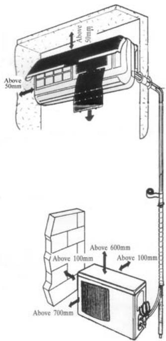
source
position
reduce
ceiling,
Outdoor Unit
- In case that you put up a canopy to protect it from rains and sunrays, pay attention not to cause any obstacles for the heating dispersion for the condenser.
- Don't keep animals or plants near the installation location for the hot air from the outdoor unit will affect them.
- Make sure to have the distance specified in the picture between ceiling, wall, furniture and other obstacles.
- Stay away from heating source and inflammable air.
- The installation base and supporting frame should be strong and secure. The machine should be at a level surface.
Installation of the Outdoor Unit
The outdoor unit must be firmly fixed avoid falling in strong wind.
Install on the cement base as in the drawing.
- If it is installed at seaside or at a place
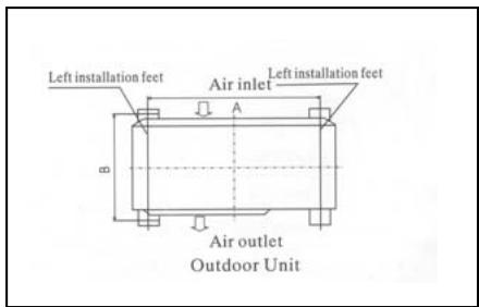
to
high
above the ground and with strong wind, the AC should be installed against the wall to ensure the normal operation of the fan and the blocking plate should be used.
- If it is an overhanging installation, the structure of the mounting wall should be made of solid, cement or materials with equivalent strength, and of sufficient support capacity. Otherwise, measures such as reinforcement, support or vibration damping should be adopted.
Installation of the Indoor Unit
- First make changes to wall and make sure that is hard and secure. Using four "+" type screws to fasten the installation board onto the wall. Keep it level in horizontal direction and perpendicular in vertical direction. Otherwise it might cause water drips when air-conditioner is running in cooling operation.
- Drill 70mm diameter pipe hole at the left lower or right lower side of the installation board. The hole shall slant outward slightly.
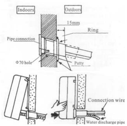
- Hang the indoor unit to the board and make sure the machine is in the middle of the board.
- Push the machine towards the left lower and right lower side of the installation board until the hangers enter tightly into the grooves (it produces "click" sound)
Check the water discharge
- Take off the frame from the unit cover.
Take off the front frame for maintenance according to the
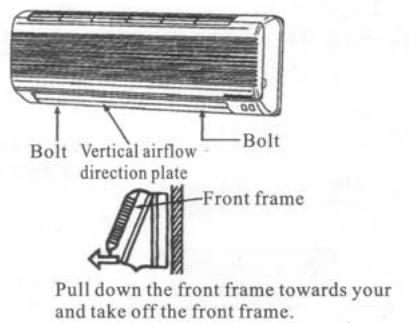

following steps:
- As shown in the picture on the right, take off two covers from the front frame and then unfasten two fixture screws.
Pull the front frame towards yourself and take it off.
To put the front frame back, reverse the steps.
You should check whether the front frame is firmly fixed into the fixture groove on the top.
2. Check the water discharge
Pour a cup of water into groove.
- Check whether the water flow through the water discharge hole.
Pipe Connection
- Connect the pipe to the unit: point to the pipe and fasten the connection screw at hand and then by wrench until it is fastened. The fastening direction is the picture.

center of first by tightly shown in
- Pointing towards the center of pipe, fasten with strength.
Wrench the screw in the end until you hear
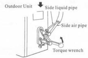
the screw
the

The fixing of pipe
- Wrap up all pipe, water discharge and connection wire from top to below.
- Cover the connection parts with insulation material and fix them with plastic rings.
- Wrap up the pipes with tape alongside and fix them to the wall with clips.
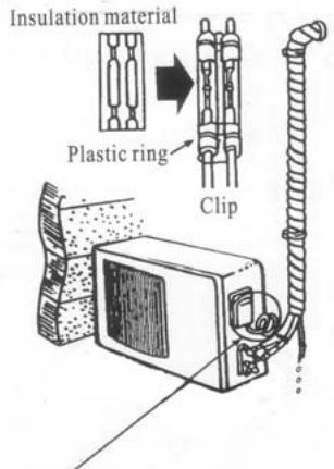
Round in this shape to prevent water entering the electrical parts.
two
the wall These
steps are usually adopted when outdoor unit is installed below the indoor unit.
-
In case that you want to have additional water discharge pipe, the end of pipe should be within certain distance from the floor (to prevent water from draining back into the pipe). Fix it onto the wall so it won't be swayed by wind.
-
Wrap the pipes and connection wire below to top.
-
Wrap up the pipes that are rounded way shown in the picture so it can water from entering the room.
Use clips or other fixture to fasten to the walls.

well from
up in the prevent
the pipes
Expelling the air in the pipes and the indoor unit
Expelling the air: humid air in the refrigerating system might cause trouble of compressor.
Take off the cover from the stop and T-branch valve.
Take off the auxiliary cover from T-branch valve.
-
Turn the stop valve rod anti-clock an angle of 90 degree, keep it open seconds and close the valve.
-
Check whether there is air leakage connection parts of pipes.
-
Push the top rod of T-branch valve hexagon wrench to expel air.
Repeat the third and fifth steps.
-
Open the stop and T-branch valve with a hexagon wrench to make the unit operate.
-
No leakage is allowed, please check all the piping connection parts. You must test the leakage, generally, it can be tested by soap water.
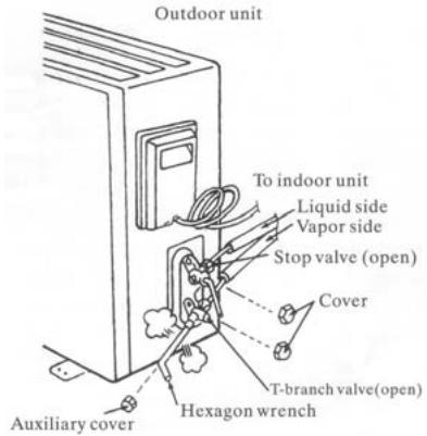
valve
the
wise to
for 8
at all
by
Electrical connection
-
Unscrew the screw, take off the control panel cover from the unit.
-
Cooling type: connect the wire to the related connection point on the panel and connect the signal connection plug.
Remarks: yellow and green cord should be connected to connection point with mark.
- Fasten the fixture of wire to control panel.
- Screw up the control panel cover to its original place.
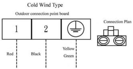
Test running
Connect the wire to independent power source socket.
Preparation of remote control.
Run the air-conditioner in cooling operation mode for 30 minutes or longer.
- Performance evaluation
Test the out and in air temperature.
Make sure that the temperature difference between the out and in air is greater than 8^ .
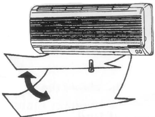
Discharged air
Items of attention
Fix the machine firmly, otherwise it will produce noise and vibration.
Install the outdoor unit where it will not disturb your neighbor.

Electrical connection diagram:
COOL SERIES
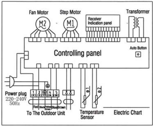
HEAT PUMP
Indoor unit electric connection diagram
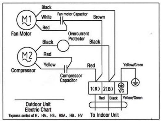
COOL SERIES

HEAT PUMP
Outdoor unit electric connection diagram
Chapter 8 Fault Analysis of the Product Available and
Typical Examples
1 Procedure of deciding the faults
Before maintaining the air conditioner, firstly you should know the phenomena of the faults decide the location of the faults, analyze the reason the faults occur, and then search for ways to solve the faults. The detailed procedures are: Look, Listen, Touch, Measure, Analyze
Look: Observe air conditioner's running. I.e., vibration; condensation on evaporator; leakage; electrical and mechanical connection, etc.
Listen: Listen to kinds of sounds of the running air conditioner. Identify the abnormal noise from the sounds.
Touch: Touch the key position and position faulty. Touch the temp of air circulation to decide the heating or cooling effect; as far to abnormal sound, besides adopt "listen", you should touch the frame, the pipe of the air conditioner to feel the vibration. Touch the easily heated parts, i.e. compressor, motor; touch them to feel the temp. (Warning: High temp).
Measure: Measure the parameters of the air conditioner and relevant parts by some instruments. Usually used instruments: amperometer, voltmeter multimeter thermometer, etc., i.e., Use multimeter to test whether the capacitor is open, the insulation of the wire and the parameters of other electrical parts; use the thermometer to measure temp of airflow.
Analyze: Analyze the above results, decide the reason and location of faults, and seek the solutions.
2 Types of Normal Faults
The type of faults is various. The normal faults can come down to six types: leaks, block, open circuit, burnt, lock, scrape.
Leak Mainly is leakage of R407C from cooling pipe system and parts; leakage of condensation water from indoor units; electrical leakage from electrical system and wires.
Block Mainly is block of the pipe system, block of capillary, block of strainer or valve.
Open Circuit Mainly is open circuit of electrical circuit, include: fuse blowing out, connectors broke.
Burnt Mainly is burnout of fan motor, of compressor, of capacitor, of transformer.
Lock Mainly is lock of compressor, four-way valve.
Scrape Mainly is scrape of indoor/outdoor fan and nearby parts, and sound abnormally.
3 Examples
3.1 Leakage and seepage of indoor unit
| Reason | Check to be made | Proposed remedy |
| Improper installation.
Indoor drain position is lower than outdoor or slanting installation of indoor unit | Observe if the condensation water drain out, if the indoor unit is declining | Level the indoor unit and adjust the height |
| Water collecting plate is blocked | Check if the plate is blocked | Remove the matters block the plate |
| Water collecting plate or drain pipe is cracked | Check the location, ensure if it is cracked | Replace the plate or pipe |
| Loosen wrap belt, heat-preservation layer is bad or layer behind indoor units is bad | Connecting pipe bleed the water, condensation water exists behind the indoor unit, the wall is wet and turn colors | Rewrap the connecting pipe, add new heat-preservation layer |
| High ambient relative humidity, low temp/speed of air flow | Water is blow out from air outlet, or water drips from the outlet. Lower speed of air flow | Suggest set the units to dehumidifying mode at high speed of air flow, to lower relative humidity; if the high speed is still felt lower, the fan motor must be checked |
3.2 Poor cooling or heating effect
| Reason | Check to be made | Proposed remedy |
| The cooling/heating load of the room is heavy or the room is not closed perfectly | Calculate the area of the room, check the close of the room | Enlarge the capacity of the units, improve the leakproofness of the room |
| Insufficient refrigerant R407C | Measure the operating current | Add R407C welding the leaked point |
| Too much R407C | Air intake temp is too low, condensation water on air intake pipe is too much, temp of discharge is too high | Discharge a little R407C |
| Effect of heat exchange is too poor | Dust on outdoor condenser and indoor filter is too much | Cleanup filter and condenser |
| Some of the windings of motor fan is short-circuit, so cause speed decline | Speed of indoor/outdoor fan is too low, air circulation is small | Repair or replace motor |
| Running condition is too bad | Check if the installation is proper; outdoor temp is too high when heating | Improve the condition, use auxiliary heating |
| Convexity exists in compressor or valve or lock of compressor | No high-low pressure difference, no clear temp difference in air intake inlet or discharge outlet of compressor | Replace compressor or valve |
| Openness of check valve is too small or the system partly or completely blocked | Check the openness; partly frost on outdoor pipe system | Open the valve; use high pressure N2to clean out the block |
3.3 Big noise or abnormal sound
| Reason | Check to be made | Proposed remedy |
| Foreign matters in wind guide or impeller fan | Check if they are | Clear away |
| Fan is distorted or in bad balance | Check them | Replace indoor/outdoor fan |
| Improper location of fan, so fan touches the housing | Open the unit or move the fan manually, find the location | Adjust the position |
| Bearing of the fan is sluggish or destroyed | Check the bearing | Replace the bearing |
| Connecting pipe vibrates due to improper installation, or touch the lower frame | Check the connecting pipe | Tidy up the pipes, eliminate the noise source |
| Outdoor pipes touches | Check the vibration of the pipes, check if them touch | Tidy up the pipes |
| Abrasion of the parts of compressor | Check if the sound of compressor is normal | Replace the compressor |
3.4 Frequently switch on/off of the compressor
| Reason | Check to be made | Proposed remedy |
| Running voltage is too low | Measure the voltage | Add measures of voltage stabilization |
| Discharge temp is too high caused by insufficient of R407C, compressor is protected by overheat | Check condensation of air intake pipe or measure if operating current is lower than rated current | Check leakage point, welding or add R407C |
| Temp sensor is too close to evaporator or moved | Check the position of sensor | Adjust the position or replace the sensor |
| Air inlet/outlet of heat exchange is blocked or low speed of fan motor; indoor air filter is too dirty or blocked | Check indoor/outdoor heat exchange, speed of motor, air inlet/outlet | Cleanup the filter, remove the obstacle |
| Too much R407C | Too much condensation water on air intake pipe, high operating current | Discharge a little R407C |
| Bad insulation of compressor, high operating current, overcurrent proof | Check start or operating current | Replace compressor |
| Improper temp set | Check actual ambient temp | Reset |
3.5 Promptly protected by halt after compressor starts
| Reason | Check to be made | Proposed Remedy |
| Insufficient R407C | Little or no condensation water on air intake pipe, operating current is lower than rated current | Add R407C |
| Mixed with air in the system, vacuum is not good | Power varies when running | Vacuumize the system, recharge R407C |
| Blocked caused by water or impurity | Operating current is lower than rated current, part of the unit frosts heavily | use high pressure N2to clean out the block, revacuumize and recharge R407C |
| Damaged compressor, high start current | Check the windings and insulation of compressor and if it is locked | Replace the compressor |
3.6 The units blow out cool air when in heating mode
| Reason | Check to be made | Proposed Remedy |
| Four-way valve doesn’t work | Listen to the units if there is sounds of valve’s working when heating or cooling | Replace the valve |
| Faults of control interruptor or other relevant circuits of the valve | Check the circuit | Repair or replace the control board |
| Insufficient R407C causes the insufficient heating capacity | Little condensation water on outdoor air intake pipe, low operating current | Add R407C |
| Connexity of compressor | Same temp of air intake inlet and discharge outlet of the compressor, no condensation in air intake inlet | Replace the compressor |
3.7 The units doesn't work
| Reason | Check to be made | Proposed Remedy |
| Bad connection of the power plugs, or no power plug | Check the socket | Repair or replace |
| Outdoor fuse or indoor fuse is burnt | Check if the fuse is good | Replace the fuse |
| Low voltage | Measure the voltage | Heighten the voltage of the power supply system |
| Wrong indoor temp set | Measure actual indoor temp, compare to the set temp(in cooling set temp should be lower than the actual, in heating, is higher) | Reset the temp |
| Wrong running mode of indoor units set | Check if running mode of two indoor units is the same( it is not available if one is heating and another is cooling | Reset |
3.8 Cannot receive the remote control signal
| Reason | Check to be made | Proposed Remedy |
| Damaged remote control or low battery | Check if the indication is normal | Replace the remote control or battery |
| Short-circuit of connections of main control board to switch board | Check the board | Replace the components |
| Running mode of two indoor units is not the same | Check if one is heating and another is cooling | Reset |
| Indoor units are in test mode | Open the air intake grill to see the running mode | Adjust test mode to remote control mode |
Remarks The above mentioned "faults" are the faults possibly occur, we will continue to collect the faults and analysis.
Chapter 1 photos and Features of products
Features of outlook and construction
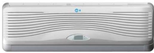
ASW-H24A4/HSAR
ASW-24A4/HSAR
ASW-H24B4/HSAR
ASW-24B4/HSAR
Deep × width × high 335× 1153× 190
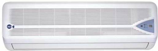
ASW-H24A4/HSR
ASW-24A4/HSR
ASW-H24B4/HSR
ASW-24B4/HSR
Deep × width × high(335 × 1153 × 190
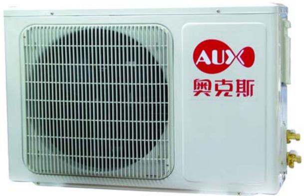
Deep × width × high 300× 800× 690
All types
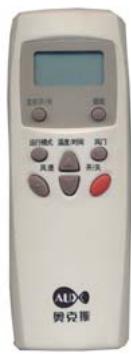
All types
Operation interface
Inner operation interface of Type HSAR

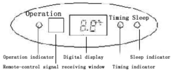
Inner operation interface of Type HSR


Emergency operation button of indoor types:
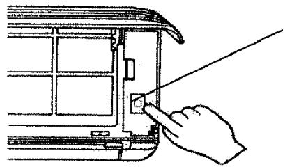
1) When the air-conditioner works with the absence of remote control, it will stop
working by pressing the compulsory button and it will resume working by pressing the compulsory button once again.
2) When remote control is useless, you can adopt the compulsory operation by which the air conditioner will go into automatic operation mode.
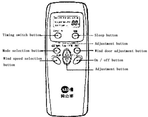
The operation interface of remote control:
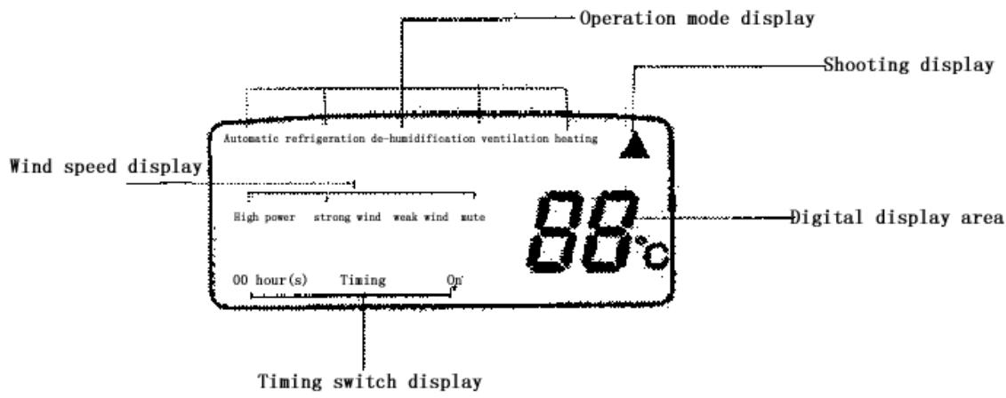
Features of products
- Fashionable appearance
- Compact Design
3.7 Hours of Sleep Mode Operation
- Economy Mode to Reduce Electrical Power Consumption
- Clean breath efficient biological antibacterial filter gauze made from green plant elite refined by using international leading technology, with the function of filtering and suppressing bacteria, and able to absorb and kill various pathogens and harmful gases efficiently for a long period, prevent secondary pollution caused due to microorganism spreading, and ensure the health of your family
- R407c cold medium is applied, environment-friendly, and avoid damages to ozonosphere
- International famous-brand Toshiba Hitachi and Matsushita compressors are applied
Chapter 2 Operating Principle
. Cooling
After the power supply is switched on, the machine is set to COOL mode. With the compressor being operated, the low-temperature and low-pressure refrigerant vapor is sucked into the compressor where it is turned into high-temperature and high-pressure gas. Then it is cooled down in the outdoor heat exchanger by the air and becomes liquid. After being throttled by the capillary, the refrigerant liquid comes into the indoor unit and then it evaporates in the indoor heat, exchanger, absorbing heat and reducing the room temperature. The evaporated refrigerant vapor returns to the outdoor unit and is again sucked into the compressor, completing the cycle. With the refrigerant cycling being kept on, the objective of lowering the room temperature is fulfilled.
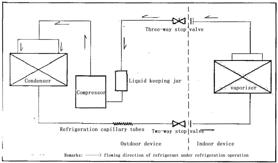
60 detachable cool series
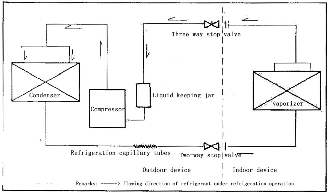
70 detachable cool series
. Heating
After the power supply is switched on, the machine is set to HEAT mode and the coil of the electromagnetic four-way valve is energized. After the compressor starts to operate, the high-temperature and high-pressure refrigerant gas first comes into the heat exchanger of the indoor unit, where it is cooled, releases heat and increases the room temperature. The cooled high-pressure refrigerant is then throttled in the outdoor unit and returns to the compressor after evaporation. With such cycles being maintained, the objective of increasing the room temperature is fulfilled.
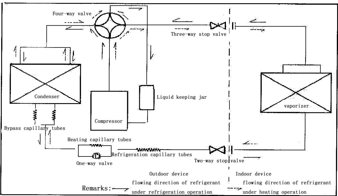
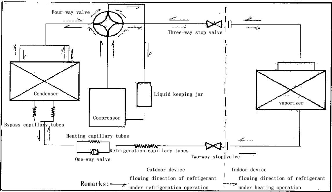
60 detachable cool & warm (type)
70 detachable cool & warm (type)
Operation Hints
Adjust room temperature properly. Set the temperature 1^ higher than actually desired. Approximately 10% of electricity costs can be saved.
Clean the air filter regularly. Blockage in the air filter reduces the airflow and lowers the cooling. Clean at least once every 2 weeks. Otherwise, 6% of electricity cost will be wasted.


Prevent waste with the Timer. Use Timer when sleeping or going out to save electricity cost.
Do not block the air outlet vents at outdoor unit. Otherwise, it will lower the cooling performance.
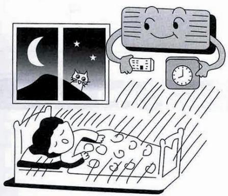
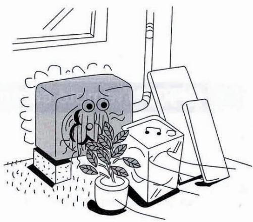
Make sure that the doors and windows are shut. Otherwise, cooling performance will be reduced and electricity cost is wasted.
Keep blinds or curtains closed. Do not let sunshine enter the room directly. 5% of electricity cost can be saved.
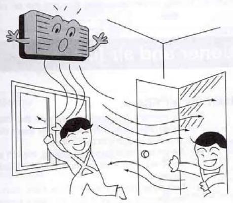
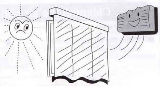
Proper airflow direction adjustment. Set the airflow direction louvers horizontal for Cooling Operation. Operation result will be better.
Use insulating material for better performance. Use insulating material during construction or renovations. It will save electricity cost.
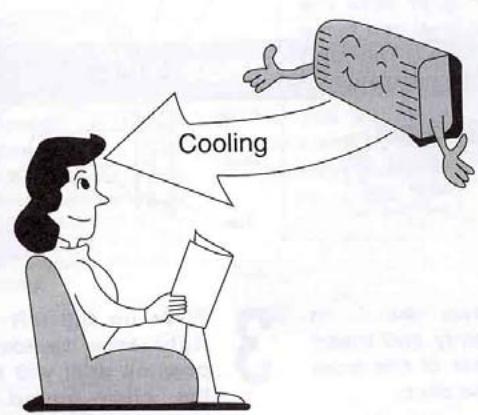
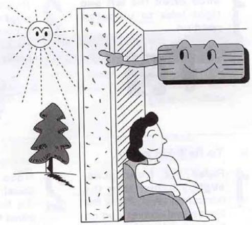
Chapter 3 operation details
1. Overall
1.1 Protection of compressor
Whatever operation modes the air-conditioner is under, there will always be 3 minutes' time-delay protection unless it is on for the first time. When the compressor is switched on, it can not be shut down within 3 minutes (except under the modes of heating or defrosting) unless it is powered off or its operation mode is changed.
1.2 The operation indicator will turn light when the air conditioner is powered on.
1.3 The buzzer will sound immediately after the controlling device receives a correct and effective signal sent by the remote control.
1.4 Timing function can be applicable to all operation modes while sleep function can only be applicable to the modes of refrigeration and heating.
2. Automatic operation mode
2.1 When the air conditioner works, it can detect the indoor temperature automatically whereby its operation mode can be selected: refrigeration, heating or dehumidification.
2.2 When the indoor temperature reaches more than 27, the air conditioner will operate under the mode of refrigeration.
2.3 When the indoor temperature reaches between 20 and 27 the air
conditioner will work under the mode of dehumidification (always mute).
2.4 When the indoor temperature reaches less than 20 , the air conditioner will work under the mode of heating.
2.5 Under this mode, the air conditioner will operate in the respect of blowing rate as set and its pendulum leaves will work according to the requirements of automatic ventilation door.
2.6 Once the operation mode is selected, it will not be able to be changed. When the air conditioner is shut down and then restarted, the operation mode will be selected once again based on the variation of indoor temperature.
2.7 After the operation indicator has been flickering for 20 seconds, it will turn light steadily (i.e. the determination of operation mode will start in 20 seconds.)
2.8 This mode has timing function, does not have sleep function.
2.9 Under this operation mode, the temperature can be set and adjusted by remote control.
3. Refrigeration mode
3.1 Under the refrigeration mode, the range of temperature set by remote control is between 16 and 32.
3.2 Shut-down of four-way valve;
3.3 The condition on which the compressor starts is that the indoor
temperature reaches more than the temperature set plus 1 while the condition on which the compressor shuts down is that the indoor temperature reaches less than the temperature set minus 1 .And when the indoor temperature is equal to that set, the original operation mode will be kept.
3.4 Under the mode of refrigeration, the function of preventing indoor coiled pipe from being frozen will be effective.
3.5 The indoor wind speed will be as set. And the pendulum leaves will work according to the instructions sent by remote control.
4. Dehumidification operation
4.1 The temperature range set and controlled is between 16 and 32 . The temperature will be set by remote control.
4.2 The four-way valve is shut down.
4.3 The wind speed gear-changes to "mute". And the pendulum leaves works according to the instructions sent by remote control;
4.4 The function of preventing indoor coiled pipe from being frozen is effective.
4.5 When the indoor temperature reaches less than 16, the function of dehumidification is out of use.
4.6 When the indoor temperature reaches more than 16, the compressor will be switched on and work intermittently. The time when the compressor shuts down depends on T ring and T ring-T set.
When the compressor is shut down, the outdoor fan and indoor fan will stop working.
When T ring ≥ 23
T set < T ring-1, the compressor will be working for 8 minutes and then stopping for 3 minutes in cycles.
T set≥T ring-1, the compressor will be working for 3 minutes and then stopping for 6 minutes in cycles.
And when T ring < 23
T set ≤ T ring-1, the compressor will be working for 3 minutes and then stopping for 4 minutes in cycles.
T set >T ring-1, the compressor will be working for 3 minutes and then stopping for 6 minutes in cycles.
5. Function of ventilation control
5.1 Under the mode of ventilation, the outdoor fan assembly will always be shut down.
5.2 The indoor fan will operate as set in the respect of air quantity without the gear- change of "high power".
5.3 The pendulum leaves will work according to the instructions sent by remote control.
6. Heating function
6.1 Under the mode of heating, the temperature range set is between 16 and 32. And the temperature will be set by remote control.
6.2 When the air conditioner is powered on, the outdoor fan, four- way valve and compressor will start at the same time while when it is shut down, the outdoor fan and compressor will be shut down at the same time and so will the four- way valve after 2 minutes' delay.
6.3 Under the mode of heating, the compressor can not be shut down within 3 minutes after it is powered on unless the operation mode is changed or the air conditioner is turned off.
6.4 There is a 3-temperature compensating function. The temperature measured at the in-blow vent minus 3 automatically can be regarded as that compared with the temperature set (This function does not exist under other circumstances).
6.5 According to the temperature set, the condition upon which the compressor will be switched on is indoor temperature ≤ temperature set-1 While the condition upon which it will be switched off is indoor temperature is indoor temperature ≥ temperature + 1 . When the indoor temperature is equal to that set, the original operation mode will be kept.
6.6 Indoor fan control:
6.6.1 Heating operation and prevention of cold wind
When the compressor works:
- During the rising process of the temperature of coiled pipe, the indoor fan will not start if the temperature of the coiled
pipes is less than 25 .
-
When the temperature of coiled pipe reaches less than 35 But more than 25, The indoor fan will work under the mode of " mute". If the temperature of coiled pipe ascends to 25 and then descends, it will stop working only when the temperature is lowered to 22.
-
When the temperature of coiled pipe reaches more than 35, the indoor fan will operate as set in the respect of wind speed. If the temperature of coiled pipe ascends to 35 And then descends, it will enter into the operation mode of " mute" only when the temperature is lowered to 30 .
6.6.2 Afterheat-blowing function:
6.6.2.1 When the compressor stop working:
- When the temperature of coiled pipe is more than 35, the indoor fan will operate as set in respect of wind speed.
- When the temperature of coiled pipe is more than 25 , but lessthan 35 , The indoor fan will operate under the mode of “ mute"
- When the temperature of coiled pipe is less than 25, the indoor fan will stop working.
6.6.2.2 The afterheat-blowing function when the air conditioner is just shut down: If the temperature of indoor coiled pipe reaches more than 30 , The indoor fan will operate under the mode of “ mute”; If
it lowers to less than 30 , the indoor fan will be shut down; And the time when the afterheat blows will last less than 40 seconds after the indoor fan is turned off.
6.7 Defrosting operation:
6.7.1 The conditions upon which the outdoor sensor goes into operation are as below:
-
Under the circumstance of heating, if T external coiled pipe is at the temperature of less than -6 which lasts 2 minutes and the accumulated working time of compressor reaches more than 50 minutes (if there is any power cut-off or shut-down by remote control, the accumulated working time of compressor shall be re-calculated), the defrosting interval will be more than 50 minutes and the compressor will be working 5 minutes continually.
-
If there is any damage to the external coiled pipe, the accumulated working time of compressor will reach 50 minutes (if there is any power cut-off, shut-down by remote control or defrosting, the accumulated working time of compressor shall be re-calculated) and the defrosting operation will last 10 minutes.
6.7.2 Once one of the following conditions is satisfied, the defrosting will end:
- The temperature of T external coiled pipe is more than 12 .
- Defrosting duration is more than 12 minutes.
6.7.3 The requirements of defrosting operation:
-
Sleep indicator flickers at the speed of 1 time per second
-
When defrosting operation starts, the compressor and indoor fan will stop working while outdoor fan and four-way valve will continue to work.
-
The four-way valve and outdoor fan will stop operating in 30 seconds.
-
15 seconds after that, the compressor starts and goes into defrosting operation.
-
After the defrosting ends, the compressor stops working. And the four-way valve and outdoor fan begins to work in 20 seconds.
-
20 seconds after that, the compressor starts and goes into heating operation. And the indoor fan enters into the prevention mode of cold wind.
6.8 Auxiliary electric heating function
6.8.1 Only if the following conditions are satisfied under the heating operation, can the auxiliary electric heating go into operation automatically.
a. The compressor works for 4 minutes by heating pump
b. Indoor temperature is less than 22 ;
c. The temperature set-indoor temperature is more than 3 ;
d. Indoor fan goes into operation;
e. Indoor coiled pipe temperature is less than 48
6.8.2 Once one of the following conditions is satisfied, auxiliary electric heating operation will end:
a. Indoor temperature is more than 22 .
b. The temperature set -indoor temperature is less than 2 .
c. When Indoor coiled pipe temperature is more than 52 , theelectric heating operation will end.
d. Indoor temperature sensor becomes abnormal.
6.8.3 If compressor or indoor fan stops working, the electric heating will stop operating as well.
6.8.4 During the operation of compressor, if the auxiliary electric heating stops working, it can be restarted only in 1 minute.
7. Sleep operation
7.1 When the air conditioner enters into the mode of sleep, the indoor wind speed will turn into the air quantity of "mute".
7.2 When the sleep operation goes under the mode of refrigeration, the temperature set rises by 1 automatically every one hour. And the air conditioner will be powered off after sleep mode has worked for 7 hours.
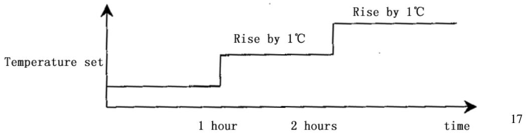
7.3 When the sleep operation goes under the mode of heating, the temperature set drops by 2 automatically every one hour. And the air conditioner will be powered off after sleep mode has worked for 7 hours.

7.4 When the button of mode selection is pressed down, the function of sleep will be cancelled.
7.5 Sleep operation is effective under the modes of refrigeration and heating. When sleep button is pressed down, the sleep operation can begin or end.
7.6 Sleep function does not exist under the automatic mode, the situation of dehumidification or the circumstance of ventilation.
8. Timing operation
8.1 When timing is set, timing indicator will turn light.
8.2 The time set by timing is 12 hours at most. The timing unit is 1 hour. Even if the operation mode is changed, the timing function will still work.
8.3 Power-off at a fixed time
The power-off at a fixed time can be set only if the air conditioner is on. And it continues to work though the power-off at a fixed time has been already set. When it comes to the fixed time, the indoor and outdoor fans will be shut down.
8.4 Power-on at a fixed time
The power-on at a fixed time can be set only if the air conditioner is on. And it continues to be off though the power-on at a fixed time has been already set. When it comes to the fixed time, the indoor and outdoor fans will start to operate.
9. Emergency switch
When the soft-touch switch is pressed, the air conditioner will be powered on and the operation indicator will flicker (1 time per second). And it goes into the mode of automatic operation in 20 seconds. When the soft-touch is pressed once again, it will be powered off. When the air conditioner goes under the mode of automatic operation, the air door will assume the appearance of automatic air door. Under the mode of heating or refrigeration, the temperature set will be 24 and the wind speed will turn that under the "high power" mode. Under the dehumidification operation, the temperature set will be T ring-2 and the air conditioner can work upon the instructions sent by remote control.
10. Overload control and various protection functions:
10.1 Temperature control (overheat protection).
10.1.1 This function can only be applied to the mode of heating, not others.
10.1.2 When the temperature of indoor coiled pipe reaches more than 57, outdoor fan will stop working.
10.1.3 When the temperature of indoor coiled pipe drops to less than 52, outdoor fan will resume to operate normally.
10.2 Temperature cut-off control function (overheat protection)
10.2.1 This function can only be applied to the mode of heating, not others.
10.2.2 When the temperature of indoor coiled pipe reaches more than 64 which lasts more than 10 seconds, the compressor and outdoor fan will all stop working.
10.2.3 After 3 minutes' shut-down, the compressor will resume to operate if the temperature of indoor coiled pipe drops to less than 52.
10.3 Function of preventing indoor coiled pipe from being frozen (supercooling protection).
10.3.1 This function can only be applied to the operation mode of refrigeration or dehumidification, not others.
10.3.2 When the temperature of indoor coiled pipe drops to -2
which lasts more than 2 minutes, the compressor will stop operating and the indoor fan will go by air quantity set.
10.3.3 When the compressor stops working, it can only be restarted only if the temperature of indoor coiled pipe rises to more than 7 or the power-off of the compressor lasts more than 6 minutes.
10.4 Protection function of short or open circuit of temperature senor
10.4.1 Powered on, when it is detected that the T ring signal sent by indoor environment temperature senor is abnormal, the air conditioner will work under the mode of heating and will not be powered off if the signal received from remote control is “heating” or it will work under the mode of refrigeration and will not be powered off if the signal received from remote control is “refrigeration” or it will work for 8 minutes and then stop for 3 minutes with the wind speed of “mute cycle dehumidification” if the signal received from remote control is “dehumidification”. Besides, the signal of automatic mode sent by remote control will not be effective, nor will the signal of automatic button power-on and the related breakdown can be indicated at the same time.
10.4.2 When it is detected that the T internal coiled pipe signal sent by indoor coiled pipe temperature sensor is abnormal, the freezing-proof, cold-wind-proof and overheat-proof functions
will be screened. Under the mode of heating, when the compressor is powered on, indoor fan will be started after 30 seconds' delay with the wind speed as set while when compressor is powered off, indoor fan will be turned off after 30 seconds' delay and the related breakdown can be indicated at the same time.
10.4.3 When it is detected that the T external coiled pipe signal sent by outdoor coiled pipe temperature sensor is abnormal, the air conditioner will work for 50 minutes, defrost for 10 minutes and heat in cycles if the signal received from remote control is “heating” and the related breakdown can be indicated at the same time while the air conditioner will not be powered off and will operate normally if the signal received from remote control is heating or defrosting or ventilation and the related breakdown can be indicated at the same time.
10.5 disposal of indoor PG electric motor abnormality
When indoor PG electric motor is loaded with voltage, the indoor fan will operate under the mode of "weak wind" automatically if the pulse signal feed backed by the indoor electric motor is not detected within 12 seconds. If the feedback signal detected is normal, the indoor fan will resume the turning speed set and the related breakdown indication will be disappear.
10.6 Function of charatron display
When the controller is normal, there will be no charatron display under the circumstance of power-off. When air conditioner is powered on, the charatron will display room temperature under the normal situation. If the temperature set is changed, the charatron will show the temperature set which sparkles at the rate of 1 time per second. Then it will display room temperature once again in 5 seconds. The display range of room temperature is 0 79 .
11. Function of breakdown indication
HS, HSA series (charatron); HV (VFD display)
| Breakdown cause | Display way | Display priority class |
| PG feedback abnormality | E4 | 1 |
| T ring abnormality | E1 | 2 |
| T internal coiled pipe abnormality | E3 | 3 |
| T external coiled pipe abnormality | E2 | 4 |
12. Adjustment function of air door direction by pendulum leaves
12.1 When the air conditioner is powered on for the first time, the pendulum leaves will move to the direction of full-opening and then to the direction of full-closing wherever they are placed.
12.2 When the air conditioner is powered off, the pendulum leaves will move up to "close" position immediately wherever they are placed after the fan comes to an end.
12.3 Under the mode of refrigeration, the pendulum leaves will first move to the full-opening position and then move to the horizontal position and at last move under the mode set while under the mode of heating, they will first move to the full-opening position and then backswing by 5 and at last work under the mode set (for details, please see the following diagram).
12.4 Pendulum wind: automatic air door and manual air door will be controlled by one button.
12.5 When the pendulum leaves move from full-opening position to full-closing position at the time of power-on or from starting position to full-closing position at the time of power-off, the speed will be 20 per second while the speed under the instruction situation will be 5 per second.
Swing angle under the mode of refrigeration: BD is 35 ± 2
Swing angle under the mode of heating: FC is 40 ± 2
Backswing angle under the mode of heating: EF is 5

13. Self-checking function of controller
After the automatic button is pressed, the air conditioner will be powered on and enter into the process of self-checking:
Buzzer sounds two times operation indicator turns on timing indicator turns on compressor acts four-way valve acts outdoor fan acts electric heating acts indoor fan acts buzzer sounds one time which means that air conditioner goes into the state of order-waiting and the self-checking comes to an end.
14. Remote control
Name and functions of the button on the remote control
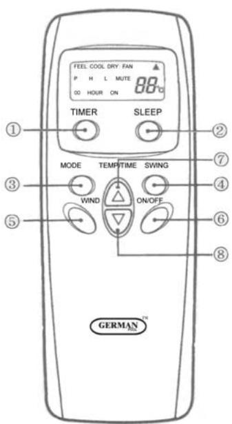
(1) Timing ON/OFF button: set the timing mode. After each pressing, the mode will be changed. It shows in the following display.

(2) Sleeping button: which enables you to start the automatic operation in sleeping mode and stops by pressing on it again.
(3) Selection button for operation mode: which enables you to select different operation modes, after each pressing, the operation mode will be changed. It shows in the following display.

Remarks: Only cool type remote control has no heat mode
(4) Wind direction adjusting button: press the button, the horizontal airflow direction plate can adjust automatically. When you have the desired wind direction, please press it again, the airflow direction plate will maintain the same position.
(5) Fan speed selection button: you can select fan speed from "Power", "High", "Low", and "Mute".

(6) ON/OFF button: you can start the air-conditioner by pressing this button and stop its operation by pressing it again.
(7) Setting button▲: Press the button, the setting temperature or timer
will increase.
(8) Setting button : Press the button, the setting temperature or timer will decrease.
Display

(1) Mode display: press the MODE button, it shows the current operation mode. You can select “Automatic”, “Cool”, “Dry”, and “Fan” “heat” operation mode. (cold wind type has no heating mode)
(2) Sending display: when the remote control sends correct and effective signal each time, the sign displays intermittently each time.
(3) Fan speed display: press the “WIND” button, the fan speed will display. You can select fan speed from “Power”, “High”, “Low”, and “Mute”.
(4) Number display: which displays the setting temperature, in the circulation operation mode, the temperature number does not display.
(5)Timer ON/OFF display: which displays the timer states, “the timer ON” and “the timer OFF” do not set at the same time.
Remark: For illustration, all display items are listed here. When the mode operates, the relevant items display on the remote control.
Application
Fix batteries
(1) Slide open the cover according the direction indicated by arrowhead.
(2). Put into two AAA new batteries, position the batteries to right electric poles (+\& -) .
(3)Put back the cover.
Make sure to connect the wire to independent power source socket before you use the remote control.
Automatic operation mode
(1) Press the MODE button, select the automatic operation mode.
(2) Press the TEMP/TIME button, set the temperature, temperature can be set at 1^ difference range from 16 - 32^ .
(3) Press the WIND button, you can select fan speed from "Power", "High", "Low", "Mute".
(4) Press the ON/OFF button, the operation indicator is on, the air-conditioner starts to operate in the Automatic mode.
Press the button again, the air-conditioner stops.
Cooling/heating operation mode (cold wind type has no heating operating)
(1) Press the MODE button, select the Cooling operation mode.
(2) Press the TEMP/TIME button, set the temperature, temperature can be set at 1 difference range from 16 - 32^ C .
(3) Press the WIND button, you can select fan speed from "Power", "High", "Low", "Mute".
(4) Press the ON/OFF button, the operation indicator is on, the air-conditioner starts to operate in the Cooling mode. Press the button again, the air-conditioner stops.
Drying operation mode
(1) Press the MODE button, select the Drying operation mode.
(2) Press TEMP/TIME button, set the temperature, temperature can be set at 1^ difference range from 16 - 32^ .
(3) Press the ON/OFF button, the operation indicator is on, the air-conditioner starts to operate in the Drying mode. Press the button again, the air-conditioner stops.
Remark: In the drying operation mode, the fan speed is automatically set to "Mute".
Circulation operation mode
(1) Press the MODE button, select the Circulation operation mode.
(2) Press the WIND button, you can select fan speed from "High", "Low", "Mute". In the circulation operation mode, you cannot select the speed of "Power".
(3) Press the ON/OFF button, the operation indicator is on, the air-conditioner starts to operate in the Circulation mode. Press the button again, the air-conditioner stops.
Remark: In the circulation operation mode, you cannot set the temperature.
Timer setting
Set the "Timer ON" (it operates only when the air-conditioner shuts off.)
(1) Press the TIMER button, select the “Timer ON”, the remote control display “00 HOUR ON”; “ON” displays intermittently.
(2) Press the TEMP/TIME button, set the time. When “ON” stops intermittently, the “Timer ON” can be set.
Set the "Timer OFF" (it operates only when the air-conditioner is running.)
(1) Press the TIMER button, select the “Timer OFF”, the remote control display “00 HOUR OFF”; “OFF” displays intermittently at the same time.
(2) Press the TEMP/TIME button, set the time. When “OFF” stops intermittently, the “Timer OFF” can be set.
Remark: The remote control can only be set within 12 hour intervals.
Sleeping operation mode
(1) Press the SLEEP button, the sleeping indicator light of indoor unit flashes.
(2) After the setting of sleeping mode, the cooling operation enables the set temperature to increase 1^ after 1 hour and another 1^ automatically after another hour.
(3) After the setting of sleeping mode, the cooling operation enables the set temperature to increase 2 after 1 hour and another 2 automatically after another hour.
(4) The air-conditioner runs in sleeping mode for 7 hours and stop automatically.
Remark: 1. in sleeping mode the fan speed changes automatically to "Mute".
- Press the MODE button, WIND button or ON/OFF button, the
remote control clears sleeping mode away.
Attention:
Aimed the remote control at the receiver on the air-conditioner.
The remote control should be within 8 meters away from the receiver.
No obstacles between the remote control and receiver.
Don't drop or throw the remote control.
Don't put the remote control under the strong sunrays or heating facilities and other heating sources.
Use two AAA batteries, don't use rechargeable batteries.
Take the batteries out of remote control before stop using for long.
When the noise of transmitting signal can't be heard from indoor unit or the transmission symbol on the display screen doesn't flare, batteries need be replaced.
If reset phenomenon occurs on pressing the button of the remote control, power of the batteries is deficient and need to be replaced.
Chapter 5 Main Technical Data
| Type | ASW-H24A4/HS
AR | ASW-24A4/HS
AR |
| ASW-H24A4/HS
R | ASW-24A4/HS
R |
| Rated cooling capacity (W/BTU) | 6000/22000 | 6000/22000 |
| Rated heating capacity (W/BTU) | 6600/22520 | |
| Rated cooling current (A) | 9.8 | 9.8 |
| Rated heating current (A) | 9.8 | |
| Rated cooling power (W) | 2150 | 2150 |
| Rated heating power(W ) | 2150 | |
| Air circulate (m³/h) | 1000 | 1000 |
| Power supply (V, Hz) | 220~240, 50 | 220~240, 50 |
| Refrigerant | R407C | R407C |
| Dehumidifying capacity(Kg/h) | 2.4 | 2.4 |
| EER | 2.8 | 2.8 |
| Noise dB(A) | Indoor unit | 48 | 48 |
| Outdoor unit | 56 | 56 |
| Dimensions(mm) | Indoor unit | 335×1153×190 | 335×1153×190 |
| Outdoor unit | 300×800×690 | 300×800×690 |
| PackingDimension(mm) | Indoor unit | 1200×390×260 | 1200×390×260 |
| Outdoor unit | 930×410×760 | 930×410×760 |
| Weight (kg) | Indoor(net/gross) | 19/21 | 19/21 |
| Outdoor(net/gross) | 54/57 | 53/56 |
| Applicable room area m2 | 25 38 | 25 38 |
| Type | ASW-H24B4/HS
AR | ASW-24B4/HS
AR |
| ASW-H24B4/HS
R | ASW-24B4/HSR |
| Rated cooling capacity (W/BTU) | 7000/24000 | 7000/24000 |
| Rated heating capacity (W/BTU) | 7700/26280 | |
| Rated cooling current (A) | 11.0 | 11.0 |
| Rated heating current (A) | 11.0 | |
| Rated cooling power (W) | 2420 | 2420 |
| Rated heating power(W) | 2420 | |
| Air circulate (m3/h) | 1100 | 1100 |
| Power supply (V, Hz) | 220~240, 50 | 220~240, 50 |
| Refrigerant | R407C | R407C |
| Dehumidifying capacity(Kg/h) | 2.8 | 2.8 |
| EER | 2.9 | 2.9 |
| Noise dB(A) | Indoor unit | 49 | 49 |
| Outdoor unit | 57 | 57 |
| Dimensions(mm) | Indoor unit | 335×1153×190 | 335×1153×190 |
| Outdoor unit | 300×800×690 | 300×800×690 |
| PackingDimension(m m) | Indoor unit | 1200×390×260 | 1200×390×260 |
| Outdoor unit | 930×410×760 | 930×410×760 |
| Weight (kg) | Indoor(net/gross ) | 19/21 | 19/21 |
| Outdoor(net/gross s) | 57/60 | 56/59 |
| Applicable room area m2 | 30 44 | 30 44 |
NOTE: 1. Specifications are standard values calculated based on rated operation conditions, they will vary in different working condition
- Our company has quick technical improvement. There will be no prior notice for any change of technical data. Please read the nameplate on the air conditioner
Chapter 6 Dismantling Procedure
Indoor Unit
| Operating step | Photo |
| 1. To remove the panel and connecting wire cover.
·Take off the screws of the connecting wire cover and remove the cover.
·Then remove the panel. | 2003/09/24 |
| 2. To remove the air filter. | 2003/09/24 |
| 3. To remove the inter frame assembly
·Take off three screws of inter frame assembly
·Then take off the inter frame assembly | 2003/09/24 |
| 4. To remove the electric control box
·Take off one screw
·Loose one obverse clip
·Remove the electric control box | 2003/09/24 |
- To remove the water-collecting plate assembly
Loose three obverse clips
Take off the electric control box
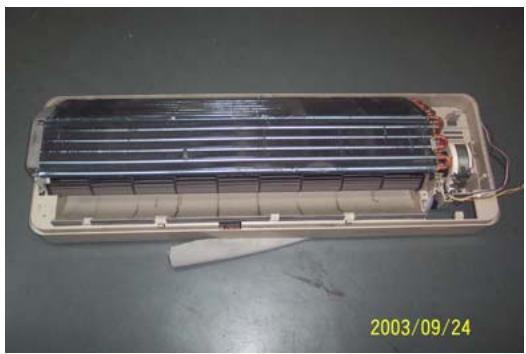
- To remove the evaporator assembly
Take off one screws of right locating cover and two screws of left locating cover
- Remove the pipe strap
- Remove the evaporator assembly
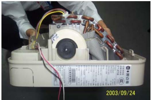
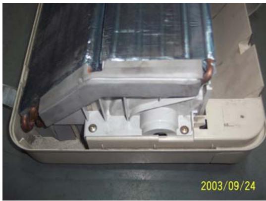
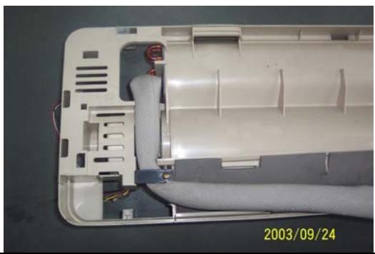
- To remove the through-flow fan
Take off the screws of though-flow fan
- Remove the though-flow fan

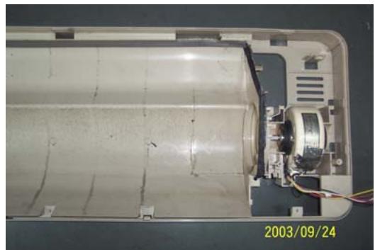
- To remove the motor
Take off three screws of right locating cover
- Remove the motor

Outdoor Unit
| Operating step | Photo |
| 1. To remove the top cover assembly
• Take off six screws of top cover | 2003/09/24 |
| 2003/09/24 |
| 2. To remove the panel assembly
• Loose screws of panel assembly
• Take off panel | 2003/09/24 |
| 3. To remove the right plate assembly
• Loose nine screws of left plate assembly
• Take off right plate | 2003/09/24 |
Chapter 7 Brief introduction of installation
The installation of air-conditioner should meet with the "Installation Instruction".
The machine must be installed correctly by professional technicians according to the "Installation Instruction".
Guide to customer
- The customer should provide a suitable power supply source, its voltage should be in the range of 90 - 110% of its rated voltage.
- The power supply circuit should have MCB leakage protection. The capacity should be more than 1.5 times of the maximum current.
- Must use independent circuit and suitable grounding socket matching with the plug of air-conditioner.
- The wiring must be installed by qualified electrician according to the electrical safety requirements.
- The air-conditioner must be well grounded, the switch of the main power of air-conditioner must be reliably grounded.
The power supply wire, must be changed by qualified electrician.
Installation Instruction
Installation order:

Testing
Selection of the installation position
Indoor Unit
There is no heating and steaming nearby.
No obstacles for installation from nearby.
- Keep good air circulation.
- Convenient to adopt measures to noises.
Don't install them near the doorway.
Make sure to have the distance specified in the picture between the wall, furniture and other obstacles.
2 meters high above the floor.

source
position
reduce
ceiling,
Outdoor Unit
- In case that you put up a canopy to protect it from rains and sunrays, pay attention not to cause any obstacles for the heating dispersion for the condenser.
- Don't keep animals or plants near the installation location for the hot air from the outdoor unit will affect them.
- Make sure to have the distance specified in the picture between ceiling, wall, furniture and other obstacles.
- Stay away from heating source and inflammable air.
- The installation base and supporting frame should be strong and secure. The machine should be at a level surface.
Installation of the Outdoor Unit
The outdoor unit must be firmly fixed avoid falling in strong wind.
Install on the cement base as in the drawing.
- If it is installed at seaside or at a place

to
high
above the ground and with strong wind, the AC should be installed against the wall to ensure the normal operation of the fan and the blocking plate should be used.
- If it is an overhanging installation, the structure of the mounting wall should be made of solid, cement or materials with equivalent strength, and of sufficient support capacity. Otherwise, measures such as reinforcement, support or vibration damping should be adopted.
Installation of the Indoor Unit
- First make changes to wall and make sure that is hard and secure. Using four "+" type screws to fasten the installation board onto the wall. Keep it level in horizontal direction and perpendicular in vertical direction. Otherwise it might cause water drips when air-conditioner is running in cooling operation.
- Drill 70mm diameter pipe hole at the left lower or right lower side of the installation board. The hole shall slant outward slightly.
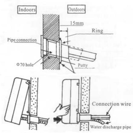
- Hang the indoor unit to the board and make sure the machine is in the middle of the board.
- Push the machine towards the left lower and right lower side of the installation board until the hangers enter tightly into the grooves (it produces "click" sound)
Check the water discharge
- Take off the frame from the unit cover.
Take off the front frame for
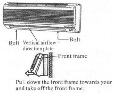

maintenance according to the following steps:
- As shown in the picture on the right, take off two covers from the front frame and then unfasten two fixture screws.
Pull the front frame towards yourself and take it off.
To put the front frame back, reverse the steps.
You should check whether the front frame is firmly fixed into the fixture groove on the top.
2. Check the water discharge
Pour a cup of water into groove.
- Check whether the water flow through the water discharge hole.
Pipe Connection
- Connect the pipe to the unit: point to the pipe and fasten the connection screw at hand and then by wrench until it is fastened. The fastening direction is the picture.
- Pointing towards the center of pipe, fasten with strength.
Wrench the screw in the end until you hear
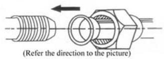

center of first by tightly shown in
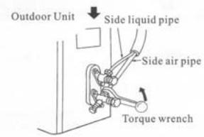
the screw
the
The fixing of pipe
- Wrap up all pipe, water discharge and connection wire from top to below.
- Cover the connection parts with insulation material and fix them with plastic rings.
- Wrap up the pipes with tape alongside and fix them to the wall with clips.

two
the wall These
steps are usually adopted when outdoor unit is installed below the indoor unit.
-
In case that you want to have additional water discharge pipe, the end of pipe should be within certain distance from the floor (to prevent water from draining back into the pipe). Fix it onto the wall so it won't be swayed by wind.
-
Wrap the pipes and connection wire below to top.
-
Wrap up the pipes that are rounded way shown in the picture so it can water from entering the room.
Use clips or other fixture to fasten to the walls.

well from
up in the prevent
the pipes
Expelling the air in the pipes and the indoor unit
Expelling the air: humid air in the refrigerating system might cause trouble of compressor.
Take off the cover from the stop and T-branch valve.
Take off the auxiliary cover from T-branch valve.
- Turn the stop valve rod anti-clock an angle of 90 degree, keep it open seconds and close the valve.
- Check whether there is air leakage connection parts of pipes.
- Push the top rod of T-branch valve hexagon wrench to expel air.
Repeat the third and fifth steps.
- Open the stop and T-branch valve with a hexagon wrench to make the unit operate.
- No leakage is allowed, please check all the piping connection parts. You must test the leakage generally, it can be tested by soap water.
valve
the
wise to
for 8
at all
by
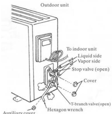
Electrical connection
- Unscrew the screw, take off the control panel cover from the unit.
Cooling type: connect the wire to the related connection point on the panel and connect the signal connection plug.
Remarks: yellow and green cord should be connected to connection point with mark.
- Fasten the fixture of wire to control panel.
- Screw up the control panel cover to its original place.

Test running
Make sure that the pipes and wires are connected.
- Make sure that both the liquid valve and gas valve on the side are completely open.
- The connection of power source
Connect the wire to independent power source socket.
Preparation of remote control.
Run the air-conditioner in cooling operation mode for 30 minutes or longer.
- Performance evaluation
Test the out and in air temperature.
Make sure that the temperature difference between the out and in air is greater than 8^ .
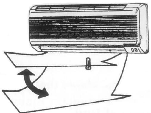
Discharged air
Items of attention
Fix the machine firmly, otherwise it will produce noise and vibration.
Install the outdoor unit where it will not disturb your neighbor.
Electrical connection diagram:
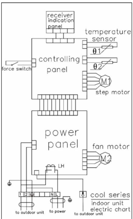
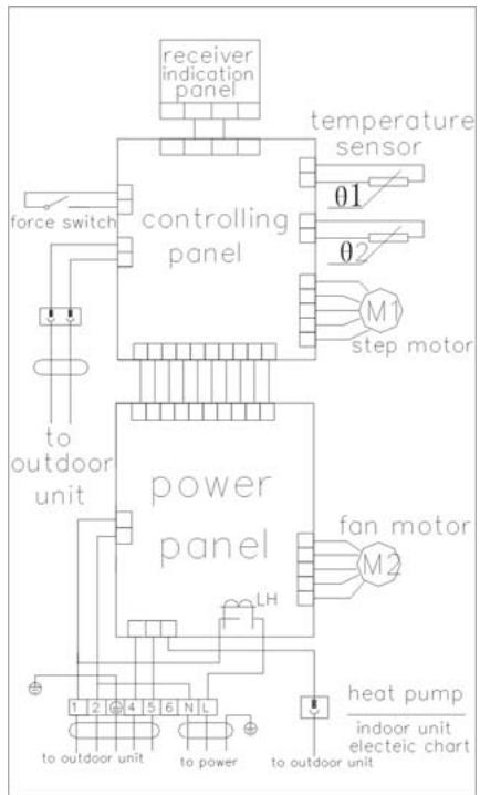
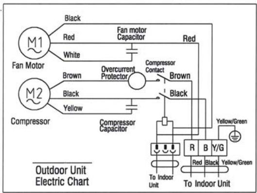
COOL indoor unit electric chart
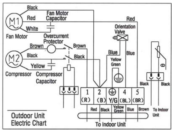
HEAT PUMP indoor unit electric chart
Chapter 8 Fault Analysis of the Product Available and
Typical Examples
1 Procedure of deciding the faults
Before maintaining the air conditioner, firstly you should know the phenomena of the faults, decide the location of the faults, analyze the reason the faults occur, and then search for ways to solve the faults. The detailed procedures are: Look, Listen, Touch, Measure, Analyze
Look: Observe air conditioner's running. I.e., vibration; condensation on evaporator; leakage; electrical and mechanical connection, etc.
Listen: Listen to kinds of sounds of the running air conditioner. Identify the abnormal noise from the sounds.
Touch: Touch the key position and position faulty. Touch the temp of air circulation to decide the heating or cooling effect; as far to abnormal sound, besides adopt "listen", you should touch the frame, the pipe of the air conditioner to feel the vibration. Touch the easily heated parts, i.e. compressor, motor, touch them to feel the temp.(Warning: High temp).
Measure: Measure the parameters of the air conditioner and relevant parts by some instruments. Usually used instruments: amperometer, voltmeter multimeter thermometer, etc., i.e., Use multimeter to test whether the capacitor is open, the insulation of the wire and the parameters of other electrical parts; use the thermometer to measure temp of airflow.
Analyze: Analyze the above results, decide the reason and location of faults, and seek the solutions.
2 Types of Normal Faults
The type of faults is various. The normal faults can come down to six types: leaks, block, open circuit, burnt, lock, scrape.
Leak Mainly is leakage of R407C from cooling pipe system and parts; leakage of condensation water from indoor units; electrical leakage from electrical system and wires.
Block Mainly is block of the pipe system, block of capillary, block of strainer or valve.
Open Circuit Mainly is open circuit of electrical circuit, include: fuse blowing out, connectors broke.
Burnt Mainly is burnout of fan motor, of compressor, of capacitor, of transformer.
Lock Mainly is lock of compressor, four-way valve.
Scrape Mainly is scrape of indoor/outdoor fan and nearby parts, and sound abnormally.
3 Examples
3.1 Leakage and seepage of indoor unit
| Reason | Check to be made | Proposed remedy |
| Improper installation.
Indoor drain position is lower than outdoor or slanting installation of indoor unit | Observe if the condensation water drain out, if the indoor unit is declining | Level the indoor unit and adjust the height |
| Water collecting plate is blocked | Check if the plate is blocked | Remove the matters block the plate |
| Water collecting plate or drain pipe is cracked | Check the location, ensure if it is cracked | Replace the plate or pipe |
| Loosen wrap belt, heat-preservation layer is bad or layer behind indoor units is bad | Connecting pipe bleed the water, condensation water exists behind the indoor unit, the wall is wet and turn colors | Rewrap the connecting pipe, add new heat-preservation layer |
| High ambient relative humidity, low temp/speed of air flow | Water is blow out from air outlet, or water drips from the outlet. Lower speed of air flow | Suggest set the units to dehumidifying mode at high speed of air flow, to lower relative humidity; if the high speed is still felt lower, the fan motor must be checked |
3.2 Poor cooling or heating effect
| Reason | Check to be made | Proposed remedy |
| The cooling/heating load of the room is heavy or the room is not closed perfectly | Calculate the area of the room, check the close of the room | Enlarge the capacity of the units, improve the leakproofness of the room |
| Insufficient refrigerant R407C | Measure the operating current | Add R407C welding the leaked point |
| Too much R407C | Air intake temp is too low, condensation water on air intake pipe is too much, temp of discharge is too high | Discharge a little R407C |
| Effect of heat exchange is too poor | Dust on outdoor condenser and indoor filter is too much | Cleanup filter and condenser |
| Some of the windings of motor fan is short-circuit, so cause speed decline | Speed of indoor/outdoor fan is too low, air circulation is small | Repair or replace motor |
| Running condition is too bad | Check if the installation is proper; outdoor temp is too high when heating | Improve the condition, use auxiliary heating |
| Convexity exists in compressor or valve or lock of compressor | No high-low pressure difference, no clear temp difference in air intake inlet or discharge outlet of compressor | Replace compressor or valve |
| Openness of check valve is too small or the system partly or completely blocked | Check the openness; partly frost on outdoor pipe system | Open the valve; use high pressure N2 to clean out the block |
3.3 Big noise or abnormal sound
| Reason | Check to be made | Proposed remedy |
| Foreign matters in wind guide or impeller fan | Check if they are | Clear away |
| Fan is distorted or in bad balance | Check them | Replace indoor/outdoor fan |
| Improper location of fan, so fan touches the housing | Open the unit or move the fan manually, find the location | Adjust the position |
| Bearing of the fan is sluggish or destroyed | Check the bearing | Replace the bearing |
| Connecting pipe vibrates due to improper installation, or touch the lower frame | Check the connecting pipe | Tidy up the pipes, eliminate the noise source |
| Outdoor pipes touches | Check the vibration of the pipes, check if them touch | Tidy up the pipes |
| Abrasion of the parts of compressor | Check if the sound of compressor is normal | Replace the compressor |
3.4 Frequently switch on/off of the compressor
| Reason | Check to be made | Proposed remedy |
| Running voltage is too low | Measure the voltage | Add measures of voltage stabilization |
| Discharge temp is too high caused by insufficient of R407C, compressor is protected by overheat | Check condensation of air intake pipe or measure if operating current is lower than rated current | Check leakage point, welding or add R407C |
| Temp sensor is too close to evaporator or moved | Check the position of sensor | Adjust the position or replace the sensor |
| Air inlet/outlet of heat exchange is blocked or low speed of fan motor; indoor air filter is too dirty or blocked | Check indoor/outdoor heat exchange, speed of motor, air inlet/outlet | Cleanup the filter, remove the obstacle |
| Too much R407C | Too much condensation water on air intake pipe, high operating current | Discharge a little R407C |
| Bad insulation of compressor, high operating current, overcurrent proof | Check start or operating current | Replace compressor |
| Improper temp set | Check actual ambient temp | Reset |
3.5 Promptly protected by halt after compressor starts
| Reason | Check to be made | Proposed Remedy |
| Insufficient R407C | Little or no condensation water on air intake pipe, operating current is lower than rated current | Add R407C |
| Mixed with air in the system, vacuum is not good | Power varies when running | Vacuumize the system, recharge R407C |
| Blocked caused by water or impurity | Operating current is lower than rated current, part of the unit frosts heavily | use high pressure N2to clean out the block, revacuumize and recharge R407C |
| Damaged compressor, high start current | Check the windings and insulation of compressor and if it is locked | Replace the compressor |
3.6 The units blow out cool air when in heating mode
| Reason | Check to be made | Proposed Remedy |
| Four-way valve doesn’t work | Listen to the units if there is sounds of valve’s working when heating or cooling | Replace the valve |
| Faults of control interruptor or other relevant circuits of the valve | Check the circuit | Repair or replace the control board |
| Insufficient R407C causes the insufficient heating capacity | Little condensation water on outdoor air intake pipe, low operating current | Add R407C |
| Connexity of compressor | Same temp of air intake inlet and discharge outlet of the compressor, no condensation in air intake inlet | Replace the compressor |
3.7 The units doesn't work
| Reason | Check to be made | Proposed Remedy |
| Bad connection of the power plugs, or no power plug | Check the socket | Repair or replace |
| Outdoor fuse or indoor fuse is burnt | Check if the fuse is good | Replace the fuse |
| Low voltage | Measure the voltage | Heighten the voltage of the power supply system |
| Wrong indoor temp set | Measure actual indoor temp, compare to the set temp(in cooling set temp should be lower than the actual, in heating, is higher) | Reset the temp |
| Wrong running mode of indoor units set | Check if running mode of two indoor units is the same( it is not available if one is heating and another is cooling | Reset |
3.8 Cannot receive the remote control signal
| Reason | Check to be made | Proposed Remedy |
| Damaged remote control or low battery | Check if the indication is normal | Replace the remote control or battery |
| Short-circuit of connections of main control board to switch board | Check the board | Replace the components |
| Running mode of two indoor units is not the same | Check if one is heating and another is cooling | Reset |
| Indoor units are in test mode | Open the air intake grill to see the running mode | Adjust test mode to remote control mode |
Remarks The above mentioned "faults" are the faults possibly occur, we will continue to collect the faults and analysis.

