
StoreEasy 1450 - Disk array HP - Free user manual and instructions
Find the device manual for free StoreEasy 1450 HP in PDF.


| Product Type | Disk Array (Storage Server) |
| Model | HP StoreEasy 1450 |
| Form Factor | 2U Rackmount |
| Height | 8.68 cm (3.41 in) |
| Width | 48.2 cm (18.98 in) |
| Depth | 73.3 cm (28.86 in) |
| Weight (max) | 25 kg (55.1 lb) without drives |
| Power Supply | Dual, hot-plug, 800W each |
| Supported Drive Bays | 12 x LFF (3.5") or 24 x SFF (2.5") |
| RAID Support | RAID 0, 1, 5, 6, 10 with smart array controller |
| Processor | Intel Xeon E5-2600 v4 series |
| Memory | 64 GB to 768 GB DDR4 |
| Network Interface | 4 x 1GbE or optional 10GbE |
| Management | HP iLO5 and OneView |
| Operating System | Windows Server or HP StoreEasy OS |
| Cooling | Hot-plug redundant fans |
| Expansion Slots | 3 x PCIe 3.0 |
| Power Consumption | Typical 500W per power supply |
| Operating Temperature | 10°C to 35°C (50°F to 95°F) |
| Security Features | Secure Boot, TPM 2.0, encryption support |
| Spare Parts Availability | HP authorized service parts: drives, fans, power supplies, controllers |
| Warranty | 3-year parts and labor |
Frequently Asked Questions - StoreEasy 1450 HP
User questions about StoreEasy 1450 HP
0 question about this device. Answer the ones you know or ask your own.
Ask a new question about this device
Download the instructions for your Disk array in PDF format for free! Find your manual StoreEasy 1450 - HP and take your electronic device back in hand. On this page are published all the documents necessary for the use of your device. StoreEasy 1450 by HP.
USER MANUAL StoreEasy 1450 HP
This document describes how to install, configure, and maintain all models of HPE StoreEasy 1000 Storage and is intended for system administrators. For the latest version of this guide, go to http://www.hpe.com/support/StoreEasy1000Manuals.
© Copyright 2012, 2016 Hewlett Packard Enterprise Development LP
The information contained herein is subject to change without notice. The only warranties for Hewlett Packard Enterprise products and services are set forth in the express warranty statements accompanying such products and services. Nothing herein should be construed as constituting an additional warranty. Hewlett Packard Enterprise shall not be liable for technical or editorial errors or omissions contained herein.
Confidential computer software. Valid license from Hewlett Packard Enterprise required for possession, use, or copying. Consistent with FAR 12.211 and 12.212, Commercial Computer Software, Computer Software Documentation, and Technical Data for Commercial Items are licensed to the U.S. Government under vendor's standard commercial license.
Links to third-party websites take you outside the Hewlett Packard Enterprise website. Hewlett Packard Enterprise has no control over and is not responsible for information outside the Hewlett Packard Enterprise website.
Acknowledgments
Microsoft® and Windows® are either registered trademarks or trademarks of Microsoft Corporation in the United States and/or other countries.
Java® and Oracle® are registered trademarks of Oracle and/or its affiliates.
UNIX® is a registered trademark of The Open Group.
Contents
1 HPE StoreEasy 1000 Storage....7
Features....7
Hardware components....7
HPE StoreEasy 1450 Storage hardware components....7
HPE StoreEasy 1550 Storage hardware components....9
HPE StoreEasy 1650 Storage hardware components....13
HPE StoreEasy 1650 Expanded Storage hardware components....16
Fan locations....19
System board components....19
DIMM slot locations....21
System maintenance switch....21
NMI functionality....22
HPE StoreEasy 1850 Storage hardware components....22
Drive LED definitions....25
Power fault LEDs....27
Front drive thermal LED....27
Systems Insight Display LED combinations....27
Installing an M.2 SSD Enablement Board in the StoreEasy 1650 Expanded Storage System......28
Removing an M.2 SSD Enablement Board from the StoreEasy 1650 Expanded server....30
Software components....31
2 Installing HPE StoreEasy 1000 Storage....33
Setup overview....33
Default roles....33
Verify the kit contents....35
Locate the serial number, Certificate of Authenticity, and End User License Agreement....35
Installing the HPE StoreEasy 1000 Storage hardware....36
Validate network information....36
Cabling HPE StoreEasy 1000 Storage....36
I/O modules ....37
Cabling guidelines....38
Single domain cabling diagrams with D6000 Disk Enclosures 40
Single domain cabling diagrams with D2000/D3000 Disk Enclosures ....40
Dual domain cabling diagrams with D6000 Disk Enclosures ....43
Dual domain cabling diagrams with D2000/D3000 Disk Enclosures 44
Connecting to HPE StoreEasy 1000 Storage....46
Power on the server and log on....47
3 Configuring HPE StoreEasy 1000 Storage....48
HPE StoreEasy Initial Configuration Tasks....48
Using Initial Configuration Tasks....48
System Settings....48
Networking....49
Notifications....50
Storage Configuration....50
Protect This Server....51
Complete system configuration....52
Using Server Core mode....52
Configuring failover properties for multi-site environments....53
Additional access methods....53
Using the Remote Desktop method....53
Using the Telnet method....53
4 Managing HPE StoreEasy 1000 Storage....54
Using the Network Configuration Tool....54
Network Interfaces....55
Network Team Configuration....56
Network VLAN Configuration....57
Network Interface IP Configuration....58
Network Configuration Summary....58
Network Validation....58
Managing the network configuration file....59
Importing network configuration....61
Using HPE StoreEasy Pool Manager....62
Calculating pool size....72
Pool Manager best practices....72
Using the HPE System Dashboard....75
Viewing the dashboard overview....76
Viewing event details....77
Viewing storage details....79
Viewing network details....82
Viewing system details....84
Managing the dashboard configuration file....86
HPE Notification System....88
5 Administration tools....90
Microsoft Windows Storage Server 2012 R2 administration tools....90
Remote Administration....90
File and Storage Services....90
Data Deduplication....90
Print Management....91
Network File System User Mapping....91
6 Storage management overview....93
Storage management elements....93
Storage management example....93
Physical storage elements....94
Arrays....95
Fault tolerance....95
Online spares....96
Logical storage elements....96
Logical drives (LUNs)....96
Partitions....97
Volumes....97
File system elements....98
File sharing elements....98
Volume Shadow Copy Service overview....98
Using storage elements....98
7 File server management....99
File services management....99
Storage management utilities....99
Array management utilities....99
HPE Smart Storage Administrator....99
Disk Management utility....100
Guidelines for managing disks and volumes....100
Scheduling defragmentation....101
Disk quotas....101
Adding storage....102
Expanding storage....102
Extending storage using Windows Storage Utilities....102
Extend volumes using Disk Management....102
Volume shadow copies....103
Shadow copy planning....103
Identifying the volume....103
Allocating disk space....104
Identifying the storage area....104
Determining creation frequency....105
Shadow copies and drive defragmentation....105
Mounted drives....105
Managing shadow copies....105
The shadow copy cache file....106
Enabling and creating shadow copies....107
Viewing a list of shadow copies....107
Set schedules....108
Viewing shadow copy properties....108
Redirecting shadow copies to an alternate volume....108
Disabling shadow copies....109
Managing shadow copies from the HPE StoreEasy 1000 Storage system desktop......109
Shadow Copies for Shared Folders....109
SMB shadow copies....110
NFS shadow copies....111
Recovery of files or folders....112
Recovering a deleted file or folder....112
Recovering an overwritten or corrupted file....112
Recovering a folder....112
Backup and shadow copies....113
Shadow Copy Transport....113
Folder and share management....113
Folder management....114
Share management....120
Share considerations....120
Defining Access Control Lists....120
Integrating local file system security into Windows domain environments....120
Comparing administrative (hidden) and standard shares....121
Managing shares....121
File Server Resource Manager....121
Quota management....122
File screening management....122
Storage reports....122
8 Management tools....123
HPE Systems Insight Manager....123
Management Agents....123
9 Troubleshooting, servicing, and maintenance......124
Maintaining HPE StoreEasy 1000 Storage....124
Determining the current HPE StoreEasy 1000 Storage software version....125
HPE System Management Homepage....125
Starting the System Management Homepage application....126
System Management Homepage main page....126
Certificate of Authenticity....129
HPE System Dashboard....129
Known issues....130
Verifying services are running....133
Error codes....134
Storage Management Provider error codes....134
Pool Manager Provider error codes....140
Management Web Service error codes....141
Hewlett Packard Enterprise Support websites....142
HPE LiveVault....143
Microsoft Systems Center Operations Manager....143
Removing and replacing hardware components....143
10 Recovering HPE StoreEasy 1000 Storage....144
System Recovery DVD....144
Using the System Recovery DVD to save system data....144
Drive letters are not assigned after a restore....145
Creating a system recovery USB flash drive using the System Recovery DVD....145
Creating a USB flash drive with an image file from Hewlett Packard Enterprise Software Depot....146
Creating a DVD with an image file from Hewlett Packard Enterprise Software Depot....146
Restoring the factory image with a DVD or USB flash device....147
Backing up and restoring HPE StoreEasy 1000 Storage with Windows Recovery Environment.....147
11 Hewlett Packard Enterprise Product Feedback....150
12 Iternity iCAS....151
13 Support and other resources....152
Accessing Hewlett Packard Enterprise Support....152
Accessing updates....152
Websites....153
Customer self repair....153
Remote support....153
Documentation feedback....153
A Operating system logical drives....154
B Network ports....155
C Warranty and regulatory information....158
Warranty information....158
Regulatory information....158
Belarus Kazakhstan Russia marking....158
Turkey RoHS material content declaration....159
Ukraine RoHS material content declaration....159
Glossary....160
Index....162
1 HPE StoreEasy 1000 Storage
The HPE StoreEasy 1000 Storage system provides multi-protocol file sharing and application storage for a range of business environments. The 14x0 and 15x0 platforms are ideal for small businesses or workgroups or a remote office. The 16x0 and 18x0 can accommodate medium and large IT environments.
NOTE: The HPE StoreEasy 1000 Administrator Guide provides information on all models within the StoreEasy 1000 Storage product family. The product name is listed generically when the same information is applicable to different models. For example, if the same information applies to 1450 and 1650, the model is listed as 1x50.
Features
The StoreEasy 1000 Storage provides the following advantages:
• Efficiently maximizing resources through file and data management without increasing costs. - Hewlett Packard Enterprise and Microsoft management integration, including Microsoft Server Manager and System Center and HPE Systems Insight Manager and iLO (Integral Lights Out). - Each system ships from the factory with preintegrated hardware and preloaded software to significantly reduce the time and complexity of installation.
For more information about StoreEasy 1000 Storage features, go to:
http://www.hpe.com/info/StoreEasy1000
Hardware components
This section provides illustrations of the StoreEasy 1000 Storage hardware components.
HPE StoreEasy 1450 Storage hardware components
The following figures show components and LEDs located on the front and rear panels of the HPE StoreEasy 1450 Storage.
Figure 1 HPE StoreEasy 1450 Storage front panel components
- Serial label pull tab 1. Optical drive (optional)
- LFF drives 3. USB connectors
Figure 2 HPE StoreEasy 1450 Storage front panel LEDs and buttons
| StatusDescriptionItem | ||
| Blue = Identification is activatedUID LED/button1Flashing blue = System is being managed remotelyOff = Identification is deactivated | ||
| 2 | power LED | Green = System is onPower On/Standby button and systemFlashing green = Waiting for powerAmber = System is in standby, but power is still appliedOff = Power cord is not attached or power supply failed |
| Green = System is on and system health is normalHealth LED3Flashing amber = System health is degradedFlashing red = System health is criticalOff = System is off. | ||
| Green = Linked to networkNIC status LED4Flashing green = Network activityOff = No network link |
Figure 3 HPE StoreEasy 1450 Storage rear panel components

- PCIe3 slot 2 (primary, associated with processor 1) 1. PCIe3 s
- Power supply 1 bay 3. PCIe3 slot 3 (secondary, associated wi
- Power supply 1 LED (optional) 5. Power supply 1 power conn
- Power supply 2 power connector 7. Power supply 2 bay
- Embedded 2x1GbE network adapter 9. Power supply 2 LF
- Video connector 11. Unit ID LED
- Dedicated iLO connector 13. USB 3.0 connectors
Figure 4 HPE StoreEasy 1450 Storage rear panel LEDs and buttons
| StatusDescriptionItem | ||
| Green = Link existsNIC link LED1Off = No link exists | ||
| Green = Activity existsNIC status LED2Flashing green = Activity existsOff = No activity exists | ||
| Blue = ActivatedUID LED/button3Flashing blue = System is being managed remotelyOff = Deactivated | ||
| Green = NormalPower supply LEDsOff = One or more of the following conditions exist:Power is unavailablePower supply failedPower supply is in standby modePower supply exceeded current limit |
HPE StoreEasy 1550 Storage hardware components
This section illustrates the components and LEDs located on the front and rear panels of the HPE StoreEasy 1550 Storage.
Figure 5 HPE StoreEasy 1550 Storage front panel components
- NIC status LED 1. Health LED
- USB 3.0 (2) connectors 3. Power button/LED
Figure 6 HPE StoreEasy 1550 Storage front panel LEDs and buttons
| StatusDescriptionItem | ||
| 1 | Power On/Standby button and system power LED j | Solid green = System onFlashing green (1 Hz/cycle per sec) = Performing power or sequenceSolid amber = System in standbyOff = No power present |
| 2 | Health LED j | Solid green = NormalFlashing green (1 Hz/cycle per sec) = iLO is rebooting.Flashing amber = System degradedFlashing red (1 Hz/cycle per sec) = System critical |
| 3 | NIC status LED j | Solid green = Link to networkFlashing green (1 Hz/cycle per sec) = Network activeOff = No network activity |
When all three LEDs described in this table and the UID button/LED on the rear panel flash simultaneously, a power fault has occurred. 2 Facility power is not present, power cord is not attached, no power supplies are installed, power supply failure has occurred, or the power button cable is disconnected. 3 If the health LED indicates a degraded or critical state, review the system IML or use iLO to review the system status.
Figure 7 HPE StoreEasy 1550 Storage rear panel components
- 750W non-hot-plug power supply
(optional)
- Power supply bay 1 of the hot-plug 750W power supply (optional)
- NIC connector 1. Power supply bay 2 of the 750W hot-plug
- Dedicated iLO port. NIC connector 2
- Slot 4 PCIe3x4 (4, 1). Slot 5 PCIe3x8 (8, 4, 1)
- Slot 2 PCIe3x4 (4, 1). Slot 3 PCIe3x8 (8, 4, 1)
- USB 2.0 connectors. Slot 1 PCIe3x16 (16, 8, 4, 1)
- Video connector. USB 3.0 connectors
Figure 8 HPE StoreEasy 1550 Storage rear panel LEDs and buttons
| StatusDescriptionItem | ||
| Solid green = NormalPower supply LED1 | ||
| Off = One or more of the following conditions exist:•AC power is unavailable•Power supply failed•Power supply is in standby mode•Power supply error | ||
| Green = Linked to networkiLO link LED2Off = No network connection | ||
| Green or flashing green = Network activityiLO activity LED3Off = No network activity | ||
| Green or flashing green = Network activityNIC activity LED4Off = No network activity | ||
| Green = Linked to networkNIC link LED5Off = No network connection | ||
| Solid blue = ActivatedUID button/LED6Flashing blue:•1 Hz/cycle per sec = Remote management or firmware upgrade in progress•4 Hz/cycle per sec = iLO manual reboot sequence initiated•8 Hz/cycle per sec = iLO manual reboot sequence in progressOff = Deactivated |
HPE StoreEasy 1650 Storage hardware components
This section illustrates the components and LEDs located on the front and rear panels of the StoreEasy 1650 Storage.
Figure 9 HPE StoreEasy 1650 Storage front panel components
- Video connector
- LFF drives
- USB connector
Figure 10 HPE StoreEasy 1650 Storage front panel LEDs and buttons
| StatusDescriptionItem | ||
| Green = System is on and system health is normalHealth LED1Flashing amber = System health is degradedFlashing red = System health is criticalOff = System is off | ||
| 2 | power LED | Green = System is onPower On/Standby button and systemFlashing green = Waiting for powerAmber = System is in standby, but power is still appliedOff = Power cord is not attached or power supply failed |
| Green = Linked to networkNIC status LED3Flashing green = Network activityOff = No network link | ||
| Blue = Identification is activatedUID LED/button4Flashing blue = System is being managed remotelyOff = Identification is deactivated |
Figure 11 HPE StoreEasy 1650 Storage rear panel components
- PCI slots (Slots 1–3 top to bottom, riser shipped) PCI Slots (Slots 4–6 top to bottom, requires second riser card, standard) and second processor)
- Optional serial port
- Rear 2 SFF HDD
- Power supply power LED 5. HPE Flexible slot power supply bay
- HPE Flexible slot power supply bay 27. Power supply power con
- Power supply power connection 9. Power supply power LED
- Embedded 4 x 1GbE network adapter 11. VGA connector
- USB 3.0 connectors (2) 13. Dedicated iLO connector
- Optional FlexibleLOM ports (Shown: 4 x 1GbE) 15. Unit ID LED
1 For the StoreEasy 1650 90TB SATA model (SKU M0S97A), the rear panel contains 3 LFF drives instead of 2 SFF drives. With 3 LFF drives, the second PCI riser cannot be added, but a second processor can still be installed.
Figure 12 HPE StoreEasy 1650 Storage rear panel LEDs
| StatusDescriptionItem | ||
| Blue = ActivatedUnit ID LED1Flashing blue = System is being managed remotelyOff = Deactivated | ||
| 2 | Power supply PowerLED | Power = System is off or power supply has failedSolid green = Normal |
| 3 | Power supply PowerLED | Power = System is off or power supply has failedSolid green = Normal |
HPE StoreEasy 1650 Expanded Storage hardware components
This section illustrates the components and LEDs located on the front and rear panels of the HPE StoreEasy 1650E (Expanded Storage).
Figure 13 HPE StoreEasy 1650E Storage front panel components
| DescriptionItem | |
| LFF hot-plug drives1 | |
| USB 2.0 connector2 |
Figure 14 HPE StoreEasy 1650E Storage rear panel components

| DescriptionItem | |
| 1 | PCIe3 x16 (16, 8, 4, 1) slot 7 for low-profile, standup expansion 1 board |
| 2 | PCIe3 x 8 (8, 4, 1) slot 6 for low-profile, standup expansion 1 board |
| 3 | PCIe3 x16 (16, 8, 4, 1) slot 5 for low-profile, standup expansion 1 board |
| LFF hot-plug drives4 | |
| 5 | PCIe3 x16 (16, 8, 4, 1) slot 2 for low-profile, standup expansion board or riser cage options 2 |
| 6 | PCIe3 x 8 (8, 4, 1) slot 1 for low-profile, standup expansion 2 board |
| 7 | FlexibleLOM slot 2 |
| Hot-plug power supply bay 18 | |
| Hot-plug power supply bay 29 | |
| USB 3.0 connectors10 | |
| NIC 1/shared iLO connector11 | |
| NIC connector 212 | |
| Video connector13 | |
| Dedicated iLO management connector14 |
1 The PCIe expansion slots 5-7 are associated with processor 2. 2 The PCIe expansion slots 1-4 and the FlexibleLOM slot are associated with processor 1.
Figure 15 HPE StoreEasy 1650E Storage front panel LEDs
![graph TD A["1"] --> B["+"] C["2"] --> B D["3"] --> B E["4"] --> B F["5"] --> G["+"] H["Switch"] --> I["+"] style A fill:#fff,stroke:#000 style C fill:#fff,stroke:#000 style D fill:#fff,stroke:#000 style E fill:#fff,stroke:#000 style F fill:#fff,stroke:#000 style G fill:#fff,stroke:#000 style H fill:…](/content/2026/06/1321655/images/9fae49a062f1576bd54a73540d025c599ad9ea6af48f13332ff8e6b138a107cc.jpg)
| StatusDescriptionItem | ||
| 1 | 1 | Solid green = NormalHealth LEDFlashing green (1 Hz/cycle per sec) = iLO is rebootingFlashing amber = System degradedFlashing red (1 Hz/cycle per sec) = System critical2 |
| 2 | 1 | Solid green = Link to networkNIC status LEFlashing green (1 Hz/cycle per sec) = Network activeOff = No network activity |
| Front drive health/thermal LED3 | Solid green = Drives supported by the SAS expander are functional3.Solid amber = Failure or predictive failure of one or more drives supported by the SAS expander3.Flashing amber (1 Hz/cycle per sec) = The temperature sensor in one or more front drives is about to reach the thermal threshold. Immediately slide the front drive cages back into the chassis and keep them there until the LED turns green4Off = No power present5 | |
| 4 | power LED1 | Solid green = System onPower On/StandbyFlashing green (1 Hz/cycle per sec) = Performing power on sequenceSolid amber = System in standbyOff = No power present5 |
| 5 | 1 | Solid blue = ActivatedUID button/LEDFlashing blue:•1 Hz/cycle per sec = Remote management or firmware upgrade in progress•4 Hz/cycle per sec = iLO manual reboot sequence initiated•8 Hz/cycle per sec = iLO manual reboot sequence in progressOff = Deactivated |
When these four LEDs flash simultaneously, a power fault has occurred.
If the health LED indicates a degraded or critical state, review the system IML or use iLO to review the system health status.
This LED behavior applies to all front drives, and to the rear drives connected to the front drive cage 2 backplane.
This LED behavior depends on the iLO 08-HD Max sensor reading.
Facility power is not present, power cord is not attached, no power supplies are installed, power supply failure has occurred, or the front I/O cable is disconnected.
Figure 16 HPE StoreEasy 1650E Storage rear panel LEDs
| StatusDescriptionItem | ||
| Solid green = Link to networkDedicated iLO actFlashing green = Network activeOff = No network activity | ||
| Green = Network linkDedicated iLO link LED2Off = No network link | ||
| Solid green = Link to networkNIC activity LED3Flashing green = Network activeOff = No network activity | ||
| Green = Network linkNIC link LED4Off = No network link | ||
| Solid blue = ActivatedUID LED5Flashing blue:•1 Hz/cycle per sec = Remote management or firmware upgrade in progress•4 Hz/cycle per sec = iLO manual reboot sequence initiated•8 Hz/cycle per sec = iLO manual reboot sequence in progress | ||
| Off = Deactivated | ||
| Solid green = NormalPower supply Off = One or more of the following conditions exists:•Power is unavailable•Power supply failed•Power supply is in standby mode•Power supply error |
Fan locations

System board components
The components shown in this section are associated with the HPE ProLiant XL420 Gen9 Se system board.

| DescriptionItem | |
| FlexibleLOM slot1 | |
| 2 | PCIe3 x 8 (8, 4, 1) slot 1 for low-profile, standup expansion board1 |
| 3 | PCIe3 x16 (16, 8, 4, 1) slot 2 for low-profile, standup expansion board or riser cage options1 |
| MicroSD slot4 | |
| TPM connector5 | |
| HPE Flexible Smart Array Controller slot6 | |
| Dedicated iLO management module connector7 | |
| 8 | PCIe3 x16 (16, 8, 4, 1) slot 5 for low-profile, standup expansion board21 |
| 9 | PCIe3 x16 (16, 8, 4, 1) slot 7 for low-profile, standup expansion board21 |
| 10 | PCIe3 x16 (16, 8, 4, 1) slot 7 for low-profile, standup expansion board21 |
| NMI header11 | |
| 12 | Storage backup power connectors for expansion slots 3-7 |
| Front I/O connector13 | |
| Processor 2 DIMM slots14 | |
| Processor 1 DIMM slots15 | |
| System battery16 | |
| Fan signal connector17 | |
| HPE Smart Storage Battery connector18 | |
| Rear SFF drive backplane detection connector19 | |
| 20 | Fan power connector |
| 21 | Front drive cage 2 backplane power connector |
| 22 | Front drive cage 1 backplane power connector |
| 23 | Storage backup power connector for expansion slots 1-2SATA 6Gb/s connector 424 |
| SATA 6Gb/s connector 525 | |
| Power pass-through board connector26 | |
| Internal USB 3.0 connector27 | |
| SATA x4 connector 128 | |
| Rear drive cage backplane power connector29 | |
| Front USB 2.0 connector30 | |
| System maintenance switchX |
The PCIe expansion slots 5-7 are associated with processor 2.
DIMM slot locations
DIMM slots are numbered sequentially (1 through 8) for each processor. The supported AMP modes use the letter assignments for population guidelines.
![graph TD A["Block P1"] --> B["Ch3 C G D H"] B --> C["1 2 3 4"] D["Block P2"] --> E["Ch2 F B E A"] E --> F["5 6 7 8"] F --> G["1 2 3 4"] H["Downward Arrow"] --> I["Ch3 C G D H"] I --> J["5 6 7 8"]](/content/2026/06/1321655/images/5cb34a116d1a67dcae860e972b114a5af5d62faa4428687373d68bc280362cf9.jpg)
The arrow points to the front of the server.
System maintenance switch
| FunctionDefaultPosition | ||
| S1 Off = iLO 4 security is enabled.OffOn = iLO 4 security is disabled. | ||
| S2 | Off | Off = System configuration can be changed.On = System configuration is locked. |
| S3 | Off | Reserved |
| S4 | Off | Reserved |
| S5 | Off | Off = Power-on password is enabled.On = Power-on password is disabled. |
| S6 | Off | Off = No functionOn = ROM reads system configuration as invalid.Off = Set default boot mode to UEFI.OffS7On = Set default boot mode to legacy. |
| Reserved-S8 | ||
| Reserved-S9 | ||
| Reserved-S10 | ||
| Reserved-S11 | ||
| Reserved-S12 |
To access the redundant ROM, set S1, S5, and S6 to on.
When the system maintenance switch position 6 is set to the On position, the system is prepared to erase all system configuration settings from both CMOS and NVRAM.
△ CAUTION: Clearing CMOS or NVRAM or both deletes configuration information. Be sure to properly configure the server, if not data loss could occur.
IMPORTANT: Before using the S7 switch to change to Legacy BIOS Boot Mode, be sure the HPE Dynamic Smart Array B140i Controller is disabled. Do not use the B140i controller when the server is in Legacy BIOS Boot Mode. Do not change the BIOS from UEFI to Legacy BIOS mode on the StoreEasy 1650 Expanded Storage system. The operating system M.2 SSDs are connected to the B140i. The B140i is only accessible when the system is in UEFI mode.
NMI functionality
An NMI crash dump creates a crash dump log before resetting a system which is not responding. Crash dump log analysis is an essential part of diagnosing reliability problems, such as failures of operating systems, device drivers, and applications. Many crashes freeze a system, and the only available action for administrators is to restart the system. Resetting the system erases any information which could support problem analysis, but the NMI feature preserves that information by performing a memory dump before a system reset.
To force the system to invoke the NMI handler and generate a crash dump log:
- Use the iLO Virtual NMI feature.
- Short the NMI header ("System board components" (page 19)).
For more information, see the Hewlett Packard Enterprise website http://www.hpe.com/support/NMI.
HPE StoreEasy 1850 Storage hardware components
This section illustrates the components and LEDs located on the front and rear panels of the HPE StoreEasy 18x0 Storage.
Figure 17 HPE StoreEasy 1850 Storage front panel components
- Quick release levers (2)1. Video connector
- USB connector3. Drive bays
Figure 18 HPE StoreEasy 1850 Storage front panel LEDs and buttons
| StatusDescriptionItem | ||
| 1 | and system power LED | Off = Power cord not attached or power supply failurePower On/Standby buttoSolid Amber = System is in standby; Power On/Standby Button service is initializedFlashing Green = Power On/Standby Button has been pressed; system is waiting to power onSolid Green = System on |
| Green = NormalSystem health LED2Flashing amber = System degradedFlashing red = System criticalTo identify components in degraded or critical state, see “Systems Insight Display LED combinations” (page 27) | ||
| Off = No network linkNIC status LED3Solid green = Link to network | ||
| Flashing green = Network activity | ||
| Solid blue = ActivatedUID LED and button4Flashing blue = System being remotely managedOff = Deactivated |
Figure 19 HPE StoreEasy 1850 Storage rear panel components

- PCI slots (Slots 1–3 top to bottom, riser shipped) PCI slots (Slots 4–6 top to bottom, requires second riser card, standard) and second processor)
- Rear 2 SFF HDD3. Optional serial port
- Power supply power LED5. Flexible slot power supply bay 1
- Flexible slot power supply bay 27. Power supply power connection
- Power supply power connection9. Power supply power LED
- Embedded 4 x 1GbE network adapter11. VGA connector
- USB 3.0 connectors (2)13. Dedicated iLO connector
- Optional FlexibleLOM ports (Shown: 4 x 1GbE)15. Unit ID LED
Figure 20 HPE StoreEasy 1850 Storage rear panel LEDs
| Item | Description | Status |
| 1 | Unit ID LED | Blue = ActivatedFlashing blue = System is being managed remotely.StatusDescriptionItem |
| Off = Deactivated | ||
| 2 | LED | Off = System is off or power supply has failedPower supply Power Solid green = Normal |
| 3 | LED | Off = System is off or power supply has failedPower supply Power Solid green = Normal |
Drive LED definitions
Figure 21 (page 25) shows the drive LEDs. These LEDs are located on all Hewlett Packard Enterprise hot-plug hard drives.
Figure 21 SFF Drive LEDs
| DefinitionStatusLEDItem | |||
| The drive is being identified by a host application.Solid blueLc | |||
| Flashing blue | The drive carrier firmware is being updated or requires an update. | ||
| Drive activityRotating greenActivity ring2 | |||
| No drive activityOff | |||
| 3 | Do not remove | Solid white | Do not remove the drive. Removing the drive causes one or more of the logical drives to fail. |
| Off | Removing the drive does not cause a logical drive to fail. | ||
| 4 | Drive status | Solid green | The drive is a member of one or more logical drives. |
| Flashing green | The drive is rebuilding or performing a RAID migration, stripe size migration, capacity expansion, or logical drive extension, or is erasing. | ||
| Flashing amber/green | The drive is a member of one or more logical drives and predicts the drive will fail. | ||
| Flashing amber | The drive is not configured and predicts the drive will fail. | ||
| Solid amber | The drive has failed. | ||
| Off | The drive is not configured by a RAID controller. |
Figure 22 LFF Drive LEDs
| DescriptionItem | |
| Fault/UID (amber/blue)1 | |
| Online/Activity (green)2 |
| Online/Activity LED(green) | (amber/blue) | DefinitionFault/UID LED |
| On, off, or flashing | blue | One or more of the following conditions exist:Alternating amber and•The drive has failed.•A predictive failure alert has been received for this drive.•The drive has been selected by a management application. |
| One or both of the following conditions exist:Solid blueOn, off, or flashing•The drive is operating normally.•The drive has been selected by a management application. | ||
| Amber, Flashing (1 Hz) | A predictive failure alert has been received for this drive. Replace the drive as soon as possible. | |
| The drive is online but is not currently active.OffOn | ||
| Flashing (1 Hz) | Amber, Flashing (1 Hz) | Do not remove the drive. Removing the drive might terminate the current operation and cause data loss.The drive is part of an array that is undergoing capacity expansion or stripe migration, but a predictive failure alert has been received for this drive. To minimize the risk of data loss, do not remove the drive until the expansion or migration is complete. |
| Flashing (1 Hz) | Off | Do not remove the drive. Removing the drive might terminate the current operation and cause data loss.The drive is rebuilding, erasing, or is part of an array that is undergoing capacity expansion or stripe migration. |
| Flashing (4 Hz) | Amber, Flashing (1 Hz) | The drive is active but a predictive failure alert has been received for this drive. Replace the drive as soon as possible. |
| The drive is active and is flashing (40Hz)Off | ||
| Off | Solid amber | A critical fault condition has been identified for this drive and the controller has placed it offline. Replace the drive as soon as possible. |
| Amber, Flashing (1 Hz) | A predictive failure alert has been received for this drive. Replace the drive as soon as possible. | |
| OffOff | The drive is offline, a spare, or not configured as part of an array. |
Power fault LEDs
The following table provides a list of power fault LEDs and the subsystems that are affected. All power faults are used by all servers.
| LED behaviorSubsystem | |
| 1 flashSystem board | |
| 2 flashesProcessor | |
| 3 flashesMemory | |
| 4 flashesRiser board PCIe slots | |
| 5 flashesFlexibleLOM | |
| HBA controller | 6 flashesRemovable Flexible Smart Array controller/Sn |
| 7 flashesSystem board PCIe slots | |
| 8 flashesPower backplane or storage backplane | |
| 9 flashesPower supply |
Front drive thermal LED
The thermal warning function of the front drive health/thermal LED depends on the iLO 08-HI Max sensor reading. This function is disabled under these conditions:
- There are no drives in the front drive cages 1 and 2.
- The temperature sensor in one or more front drives has failed.
Under these conditions, iLO shows the 08-HD Max sensor reading as N/A. To view temperature sensor data, log in to iLO 4 web interface and navigate to the Information→System Information→Temperatures.
If the 08-HD Max sensor reading shows N/A, observe the following when extending the front drive cage:
- Do not keep the drive cages out of the chassis for more than 140 sec.
- Keep the drive cages inside the chassis for at least 300 sec before extending them out again.
Systems Insight Display LED combinations
When the health LED on the front panel illuminates either amber or red, the server is experiencing a health event. Combinations of illuminated Systems Insight Display LEDs, the system power LED, and the health LED indicate system status.
Table 1 Systems Insight Display LEDs and internal health LED combinations
| Display LED and color | Health LEDSystems Insight LED | StatusSystem power | |
| (amber) | One or more of the following conditions might exist•Processor in socket X has failed.•Processor X is not installed in the socket.•Processor X is unsupported.•ROM detects a failed processor during POST. | ||
| Amber | Green | Processor in socket X is in a pre-failure condition. | |
Table 1 Systems Insight Display LEDs and internal health LED combinations (cont)
| Display LED and color | Health LEDSystems | Insight LED | StatusSystem power |
| One or more DIMMs have failed.GreenRedDIMM (amber) | |||
| DIMM in slot X is in a pre-failure condition.GreenAmber | |||
| (amber) | GreenAmberOver | The Health Driver has detected a cautionary temperature level. | |
| AmberRed | The server has detected a hardware critical temperature level. | ||
| The PCI riser cage is not seated properly.GreenRedPCI riser ( | |||
| One fan has failed or is removed.GreenAmberFan (amber) | |||
| GreenRed | Two or more fans have failed or are removed. | ||
| (amber) | AmberRedPower | Were supply more of the following conditions may exist:Only one power supply is installed and that power supply is in standby.Power supply fault.System board fault. | |
| GreenAmber | One or more of the following conditions may exist:Redundant power supply is installed and only one power supply is functional.AC power cord is not plugged into redundant power supply.Redundant power supply fault.Power supply mismatch at POST or power supply mismatch through hot-plug addition. | ||
| Power cap | (Affiber— | Standby | |
| Power cap (green) | — | Flashing green | Waiting for power |
| Green— | Power is available |
NOTE: For more information on troubleshooting, refer to the hardware platform information. The following list identifies the ProLiant model for each StoreEasy 1000 Storage product:
• 1450—HPE ProLiant DL160 Gen9 server
• 1550—HPE ProLiant ML110 Gen9 server
• 1650—HPE ProLiant DL380 Gen9 server
• 1650E—HPE Apollo 4200 Gen9 server
• 1850—HPE ProLiant DL380 Gen9 server
The ProLiant documentation is available at:
http://www.hpe.com/support/proliantgen9/docs
Installing an M.2 SSD Enablement Board in the StoreEasy 1650 Expanded Storage System
- Power down the server.
- Remove all power:
- Disconnect each power cord from the power source.
- Disconnect each power cord from the server.
- Extend the server from the rack.
- Remove the access panel.
- Remove the PCIe riser cage.
- Remove the M.2 SSD Enablement Board slot cover.
- Install the M.2 SSD Enablement Board.
IMPORTANT: The PCIe M.2 SSD Enablement Board does not connect to an array controller.
- Insert one end of each SATA cable into one of the SATA connectors on the M.2 SSD Enablement Board, and then insert the other end of the SATA cable into one of the ports on the server.
- Firmly seat the M.2 SSD Enablement Board into the x4 PCIe slot on the server.
M.2 SSD enablement board installed in the onboard PCIe3 x8 expansion slot 1

M.2 SSD enablement board installed in the onboard PCIe3 x16 expansion slot 2

IMPORTANT: Your M.2 SSD Enablement Board might either be a full-length or a half-length M.2 SSD Enablement Board. For information on installing either a full-length or a half-length M.2 SSD Enablement Board, see the server user guide on the Hewlett Packard Enterprise website (http://www.hpe.com/support/proliantgen9/docs).
- Install the M.2 SSD Enablement Board slot cover.
- Install the PCIe riser cage.
- Install the access panel.
- Install the server into the rack.
- Connect each power cord to the server.
- Connect each power cord to the power source.
- Power up the server.
The installation is complete.
Removing an M.2 SSD Enablement Board from the StoreEasy 1650 Expanded server
WARNING! To reduce the risk of personal injury from hot surfaces, allow the internal system components to cool before touching them.
CAUTION: To prevent damage to electrical components, take the appropriate antistatic precautions before beginning any installation, removal, or replacement procedure. Improper grounding can cause electrostatic discharge.
To remove the component:
- Power down the server.
- Remove all power:
- Disconnect each power cord from the power source.
- Disconnect each power cord from the server.
- Remove the server from the rack.
- Remove the access panel.
- Remove the air baffle.
- Open the cable management holder.
- Disconnect the SATA cables from the M.2 SSD enablement board and the system board.
- M.2 SSD SATA cable disconnection when the enablement board is installed in the onboard PCIe expansion slot 1 or 2.

- M.2 SSD SATA cable disconnection when the enablement board is installed in the PCI riser cage.

- If the M.2 SSD enablement board is installed in the PCI riser cage, remove the riser cage.
- Remove the M.2 SSD enablement board.
For detailed instructions on the removal and replacement procedures, see the HPE Apollo 42 Gen9 Server Maintenance and Service Guide available at http://www.hpe.com/support/proliantgen9/docs.
Software components
Windows Storage Server 2012 R2 Standard Edition comes preinstalled and activated on the HPE StoreEasy 1x50 Storage. The system configuration also includes the Hewlett Packard Enterprise Initial Configuration Tasks window, HPE StoreEasy tools, and Windows Server Manager, which are used to set up and manage StoreEasy 1000 Storage.
NOTE: Windows Storage Server 2012 R2 Standard Edition is installed in the Server with a GUI mode by default. You can switch to Server Core Installation mode. However, Server Core Installation mode is only supported on a StoreEasy 1000 Storage system when the operating environment does not require user interaction (such as in a data center). Any activity that requires the use of a GUI must be done in the Server with a GUI mode. For more info about installation options, see the Windows Server Installation Options article on Microsoft TechNet at:
http://technet.microsoft.com/library/hh831786.aspx
To switch to Server Core mode, see "Using Server Core mode" (page 52) for more information.
The Windows Server Manager→Tools→HP StoreEasy menu provides a collection of Hewlett Packard Enterprise and Microsoft utilities that are useful for managing StoreEasy 1000 Storage. The Initial Configuration Tasks window assists during the initial out-of-box setup by configuring items such as system settings, setting the network IP and domain of the StoreEasy 1000 Storage, configuring email alerts, registering the product, provisioning storage, and protecting your server. For more information on the ICT tasks, see "Configuring HPE StoreEasy 1000 Storage" (page 48). The HPE StoreEasy Pool Manager is used to create storage pools and assign spare drives. For more information on Pool Manager, see "Using HPE StoreEasy Pool Manager" (page 62). Using Windows Server Manager→File and Storage Services, you can also create virtual disks and place volumes on the virtual disks.
2 Installing HPE StoreEasy 1000 Storage
Setup overview
The StoreEasy 1000 Storage comes preinstalled with the Microsoft Windows Storage Server 2012 R2 Standard Edition operating system with Microsoft iSCSI Software Target included.
Default roles
This section includes the list of roles that come preinstalled with StoreEasy 1000 Storage. Table 2 (page 34) describes the default roles:
Table 2 Default roles
| Role serviceRole | |
| File and Storage Services | •File and iSCSI ServicesFile Server°○ Branch Cache for Network Files○ Data Deduplication○ Distributed File System (DFS) Replication○ File Server Resource Manager○ File Server VSS Agent Service○ iSCSI Target Server○ iSCSI Target Storage Provider (VDS and VSS hardware providers)○ Server for NFS○ Work Folders•Storage Services |
| Print and Document Services | •Print Server•Internet Printing•Line Printer Daemon (LPD) Service |
| Web Server (IIS) | •Web ServerCommon HTTP Features°- Default Document- Directory Browsing- HTTP Errors Static Content- HTTP Redirection○ Health and DiagnosticsHTTP Logging-- Logging Tools- Request Monitor- Tracing○ Performance- Static Content Compression○ SecurityRequest Filtering-- Basic Authentication- Windows Authentication○ Application Development- .NET Extensibility 4.5- ASP- ASP.NET 4.5- ISAPI Extensions- ISAPI Filters•Management Tools◦ IIS Management Console◦ IIS 6 Management Compatibility- IIS 6 Metabase Compatibility |
Verify the kit contents
Remove the contents, ensuring that you have all of the following components. If components are missing, contact Hewlett Packard Enterprise technical support.
Hardware
- StoreEasy 1000 Storage system (with operating system preloaded)
- Power cords
- Rail kit
Media and documentation
• HPE StoreEasy 1000 Storage Quick Start Guide • Safety and Disposal Documentation CD • HPE System Recovery DVD (if ordered) • End User License Agreement • Certificate of Authenticity Card
- HPE iLO Advanced including 1-year of 24x7 Technical Support and Updates Single Server License
Locate the serial number, Certificate of Authenticity, and End User License Agreement
For technical support purposes, locate the serial number of StoreEasy 1000 Storage, Certificate of Authenticity (COA), and End User License Agreement (EULA). Record the serial number and COA product key and make a print copy of the EULA as needed.
The serial number is located in several places:
- Top of the StoreEasy 1000 Storage system
- Back of the StoreEasy 1000 Storage system
- Inside the StoreEasy 1000 Storage system's shipping box
- Outside the StoreEasy 1000 Storage system's shipping box
The COA card is located inside the shipping box. There is also a COA sticker with product affixed to the top of the StoreEasy 1000 Storage system. The electronic copy of the EULA that ships with the system is available at %SystemDrive%\Windows\System32\license.rtf.
Installing the HPE StoreEasy 1000 Storage hardware
If your StoreEasy 1000 Storage system is fully racked and cabled, go to “Connecting to HPE StoreEasy 1000 Storage” (page 46).
For the 1450, 1650, 1650E, and 1850 systems, install the rail kit and insert and secure the storage system into the rack by following the HPE Rack Rail Kit Installation Instructions.
If you ordered the HPE Tower to Rack Conversion Tray Universal Kit for the purpose of installing the 1550 tower model in a rack, use the provided tower-to-rack conversion kit installation instructions to install the tower hardware into the rack.
Validate network information
Complete the tests in Table 3 (page 36) to verify network connectivity. Consult with your network administrator to confirm test results.
Table 3 Validation tests
| Successful?(Y/N)Command(s) | ||
| StoreEasy system from another system on the same network. | pingPing the IP address of the | |
| system on the same network form the StoreEasy system. | pingPing the IP address of some other | |
| Ping the name of the StoreEasy system from another system on the same network. | ping | |
| Ping the name of some other system on the same network form the StoreEasy system. | ping | |
| If you will be adding the StoreEasy system to an Active Directory domain, some additional tests include: | ||
| Ping the domain controller from the StoreEasy system. | ping | |
| Verify the network path to the domain controller and DNS servers is correct. | pathpingpathpingPATHPINGDNS server(Repeat for each DNS server)pathping(Repeat for each DNS server) | |
Additionally, Hewlett Packard Enterprise recommends that you also verify the iLO IP address and name resolution. However, this is not critical to support a file server.
Cabling HPE StoreEasy 1000 Storage
The StoreEasy systems support both single domain and dual domain cabling using HPE D2000, HPE D3000, and HPE D6000 disk enclosures, depending on the Smart Array RAID controller that is installed in the system. See Table 4 (page 37) for details. In a single domain, external disk enclosures are connected, using a single data path, to the Smart Array controller StoreEasy system. In a dual domain, external disk enclosures are connected, using two data paths, to a single Smart Array RAID controller in the StoreEasy system. For more detailed information about single and dual domains, see the technology brief entitled, "Redundancy in
- Smart Array controllers included as standard with StoreEasy 1x50 products do not support external disk enclosures. An optional Smart Array controller with external ports needs to be ordered to support external enclosures.
enterprise storage networks using dual-domain SAS configurations" located at: http://www.hpe.com/info/dual-domain-SAS-WP.
Table 4 Controller, disk enclosure, and single/dual domain support
| Controller model | Supported in StoreEasy systems | Disk enclosure supported | Single domain support | Dual domain support |
| P441 | 1650E, 1850 | YYD20001450, 1550, 1650, | ||
| YYD3000 | ||||
| NYD6000 | ||||
| P841 | 1450, 1550, 1650, 1650E, 1850 | D6000 | YYD2000, D3000, |
NOTE:
- The StoreEasy 1450 and 1550 systems come standard with a Smart Array P440 storage controller. The StoreEasy 1650 and 1850 come standard with a Smart Array P440ar storage controller. These storage controllers are used to connect to the internal disk drives, including the OS drives.
• The StoreEasy 1650E system comes standard with two controllers, P840ar and B140i.
- Optional P441 and P841 Smart Array controllers are used for connecting to external D2000, D3000, or D6000 disk enclosures.
I/O modules
The StoreEasy systems connect to the I/O modules on the D6000 and D2000/D3000 disk enclosures. Figure 23 (page 37) shows the I/O module ports on the D2600 disk enclosure, Figure 24 (page 38) shows the I/O module ports on the D2700 disk enclosure, and Figure 25 (page 38) shows the I/O module ports on the D6000 disk enclosure.
Figure 23 HPE D2600/D3600 Disk Enclosure I/O module ports
- Port 1
- Port 2
- I/O module A
- I/O module B
Figure 24 HPE D2700/D3700 Disk Enclosure I/O module ports
- Port 1
- Port 2
- I/O module A
- I/O module B
Figure 25 D6000 I/O modules
- Primary I/O module (Drawer 2)
- Primary I/O module (Drawer 1)
- Secondary I/O module or blank (Drawer 2)
- Secondary I/O module or blank (Drawer 1)
- SAS port 1 connector
- SAS port 2 connector
Cabling guidelines
This section provides information on the types of cables to be used with D3000 and D2000/D600 disk enclosures supported by the P441 controller and the cabling guidelines.
The following are the types of cables that you can use with the D3000 disk enclosures:
• HPE External 0.5m (1ft) Mini SAS HD 4x to Mini SAS HD 4x Cable • HPE External 1.0m (3ft) Mini SAS HD 4x to Mini SAS HD 4x Cable • HPE External 2.0m (6ft) Mini SAS HD 4x to Mini SAS HD 4x Cable • HPE External 4.0m (13ft) Mini SAS HD 4x to Mini SAS HD 4x Cable
The following are the types of cables that you can use with the D2000/D6000 disk enclosure
• HPE 0.5m External Mini SAS High Density to Mini SAS Cable • HPE 1.0m External Mini SAS High Density to Mini SAS Cable • HPE 2.0m External Mini SAS High Density to Mini SAS Cable • HPE 4.0m External Mini SAS High Density to Mini SAS Cable • HPE 6.0m External Mini SAS High Density to Mini SAS Cable
When connecting disk enclosures to the StoreEasy system, consider the following guidelines:
- In a single domain configuration, the secondary I/O modules on the D6000 are not used, so they might or might not be installed. The cabling diagrams in this section show the secondary I/O modules are not installed.
- For single domain configurations, the maximum number of disk enclosures supported by the P441 or P841 controller are 1 D6000, 8 D2000s, or 8 D3000s (up to 200 drives total).
- For dual domain configurations, the maximum number of disk enclosures supported by the P441 controller are 8 D2000 or 8 D3000s (up to 200 drives total).
- For dual domain configurations, the maximum number of disk enclosures supported by the P841 controller are 1 D6000, 8 D2000s, or 8 D3000s (up to 200 drives total).
NOTE:
The maximums listed are based on the number of drives per controller. Any StoreEasy system could have additional or alternate controllers installed, which would affect the overall number of supported disk enclosures. The maximum number of enclosures that can be connected to a controller is eight. - The P441 or P841 controllers support: - Up to 200 physical drives. - D2000 and D3000 disk enclosures; up to eight daisy chained in either single or dual domain configuration. - D6000 disk enclosure. Only one D6000 enclosure can be connected. Daisy chaining is not supported.
- In the cabling diagrams for the D2000/D3000 disk enclosure, the D2600 disk enclosure is used. Be aware that the cabling configuration is exactly the same for all D2000/D3000 disk enclosures.
- The D6000 disk enclosure does not support the use of SAS daisy chains; the D2000/D3000 disk enclosures support SAS daisy chains. In a SAS daisy chain, the D2000/D3000 disk enclosures are connected to each other — I/O module A from each disk enclosure is connected together and I/O module B of each disk enclosure is connected together.
- Only supported, documented cabling configurations are shown. Only cabling configurations shown in this document or in related D2000/D3000 or D6000 documentation are supported configurations.

CAUTION: When cabling a dual domain configuration, ensure that you do not connect multiple controllers in the StoreEasy system to the same disk enclosure; this is an unsupported configuration and might result in data loss. If the StoreEasy system is configured incorrectly, you attempt to use Pool Manager, Pool Manager will detect the configuration and display a message. The controllers can be connected to different disk enclosures.
Single domain cabling diagrams with D6000 Disk Enclosures
The following diagram shows StoreEasy systems in single domain configurations with D6000 disk enclosures.
Figure 26 HPE StoreEasy 1x50 with the P441 Controller
- P441 controller
- D6000 enclosure
- Connection to SAS port 1 on the primary I/O module (left drawer) of D6000 enclosure
- Connection to SAS port 1 on the primary I/O module (right drawer) of D6000 enclosure
Single domain cabling diagrams with D2000/D3000 Disk Enclosures
The following diagrams show different StoreEasy systems in single domain configurations with the D2000/D3000 disk enclosures. With these cabling diagrams, SAS daisy chains are used to connect the disk enclosures together. Figure 27 (page 41) shows cabling configuration option while using multiple ports on the P441 controller to decrease latency to enclosures.
Figure 27 HPE StoreEasy 1x50 with the P441 controller
- P441 controller
- D2000/D3000 enclosure 1
- Connection between P441 controller and port 2 on I/O module A of D2600 enclosure
- D2000/D3000 enclosure 2
- Connection between port 1 of I/O module A of D2600 enclosure 1 and port 2 on I/O module A of D2600 en
Figure 28 HPE StoreEasy 1x50 with the P441 controller in a single domain conf
- P441 controller
- D2000/D3000 enclosure 1
- D2000/D3000 enclosure 2
- D2000/D3000 enclosure 3
- D2000/D3000 enclosure 4
- Connection from P441 controller to port 2 of I/O module A on disk enclosure 1
- Connection from port 1 of I/O module A on disk enclosure 1 to port 2 of I/O module A on disk enclosure 2
- Connection from port 1 of I/O module A on disk enclosure 2 to port 2 of I/O module A on disk enclosure 3
- Connection from port 1 of I/O module A on disk enclosure 3 to port 2 of I/O module A on disk enclosure 4
Figure 29 HPE StoreEasy 1x50 with the P441 controller utilizing multiple ports performance![graph TD A["1 Server Rack"] --> B["2 Rack"] B --> C["3 Rack"] C --> D["4 Rack"] D --> E["5 Rack"] E --> F["6 Rack"] F --> G["7 Rack"] style A fill:#f9f,stroke:#333 style B fill:#ccf,stroke:#333 style C fill:#cfc,stroke:#333 style D fill:#fcc,stroke:#333 style E fill:#cff,stroke:#333 style F fill:#ff…](/content/2026/06/1321655/images/8420f817675a59262c0962d776e2637fbe3d4841514198f23763cea595f8729a.jpg)
- P441 controller
- Connection from P441 controller to port 2 of I/O module A on top of the disk enclosures in Group 2
- Group 1 of 4 D2000/D3000 enclosures
- Group 2 of 4 D2000/D3000 enclosures
- Connection from P441 controller to port 2 of I/O module A on top of the disk enclosures in Group 1
- Connections between the disk enclosures in Group 1
- Connections between the disk enclosures in Group 2
Dual domain cabling diagrams with D6000 Disk Enclosures
Figure 30 (page 44) shows StoreEasy systems in dual domain configurations with D6000 disk enclosures.
Figure 30 HPE StoreEasy 1x50 with the P841 controller in a dual domain config
- P841 controller
- Connection to SAS port 1 on primary I/O module path 1 (right drawer) of D6000 enclosure
- Connection to SAS port 1 on primary I/O module path 2 (right drawer) of D6000 enclosure
- Connection to SAS port 1 on primary I/O module path 1 (left drawer) of D6000 enclosure
- Connection to SAS port 1 on primary I/O module path 2 (left drawer) of D6000 enclosure
- D6000 enclosure
Dual domain cabling diagrams with D2000/D3000 Disk Enclosures
In dual domain configurations with the D2000/D3000 Disk Enclosures, you have the option of cabling for best fault tolerance or best performance.
Figure 31 (page 45) illustrates best fault tolerance, which provides the best data protection in the event of an I/O module failure. The disk enclosures are put into two groups of four disk enclosures each. There is always one path to the disk enclosure from the controller (from either the top disk enclosure in the group or the bottom disk enclosure in the group). The green path carries the data if the blue path is broken. Besides a controller failure, the worst case scenario is losing access to one I/O module if an I/O module fails. Figure 31 (page 45) also illustrates the SAS daisy chain between disk enclosures.
Figure 31 HPE StoreEasy 1x50 with the P441 controller in a dual domain control (best fault tolerance)![graph TD A["1 Server Rack"] --> B["2 Network Rack"] B --> C["3 Server Rack"] C --> D["4 Network Rack"] D --> E["5 Network Rack"] E --> F["6 Network Rack"] F --> G["7 Network Rack"] style A fill:#f9f,stroke:#333 style B fill:#ccf,stroke:#333 style C fill:#cfc,stroke:#333 style D fill:#fcc,stroke:#333…](/content/2026/06/1321655/images/04a60f18af76bf72029ab2cfa6cc2adabfbc4b28f27565038847211d505b3c9b.jpg)
- P441 controller
- Connection from P441 controller to port 1 of I/O module B on bottom of the disk enclosures in Group 2
- Group 1 of 4 D2000/D3000 enclosures
- Group 2 of 4 D2000/D3000 enclosures
- Connection from P441 controller to port 2 of I/O module A on top of the disk enclosures in Group 1
- Connections between the disk enclosures in Group 1
- Connections between the disk enclosures in Group 2
Figure 32 HPE StoreEasy 1x50 with the P441 controller in a dual domain config (best performance)![graph TD A["1 Server Rack"] --> B["2 Network"] B --> C["3 Server Rack"] C --> D["4 Network"] D --> E["5 Network"] E --> F["6 Server Rack"] F --> G["7 Network"] style A fill:#f9f,stroke:#333 style B fill:#ccf,stroke:#333 style C fill:#cfc,stroke:#333 style D fill:#fcc,stroke:#333 style E fill:#cff,st…](/content/2026/06/1321655/images/45edf2570af25a95a99ad4b2649ceea0ecc2316ce437ad214e9fad4e823e4524.jpg)
- P441 controller
- Connection from P441 controller to port 2 of I/O module B on top of the disk enclosures in Group 1
- Group 1 of 4 D2000/D3000 enclosures
- Group 2 of 4 D2000/D3000 enclosures
- Connection from P441 controller to port 2 of I/O module A on top of the disk enclosures in Group 1
- Connections between the disk enclosures in Group 1
- Connections between the disk enclosures in Group 2
Connecting to HPE StoreEasy 1000 Storage
Use either the direct attach or iLO method to connect to StoreEasy 1000 Storage.
IMPORTANT: Only the direct attach and iLO access methods can be used to install StoreEasy 1000 Storage. When the installation process completes and the server's IP addresses have been assigned, you can then additionally use the remote desktop method to access StoreEasy 1000 Storage.
- Direct attach—This access method is mandatory if your network does not have a DHCP (Dynamic Host Configuration Protocol) server. Connect the following cables to the back panel of StoreEasy 1000 Storage in this sequence: keyboard, mouse, network cables, monitor cable, and power cable.
NOTE: The keyboard, mouse, and monitor are not provided with StoreEasy 1000 Storage.
- iLO—Access StoreEasy 1000 Storage using the iLO remote management method:
- Connect a network cable to the iLO port located on the back of the StoreEasy 1000 Storage system.
- Connect a power cable to StoreEasy 1000 Storage.
- Locate the iLO Network Settings tag attached to the StoreEasy 1000 Storage and record the default user name, password, and DNS name.
- From a remote computer, open a standard Web browser and enter the iLO management hostname of the StoreEasy 1000 Storage.
NOTE: By default, iLO obtains the management IP address and subnet mask from your network's DHCP server. The hostname found on the iLO tag is automatically registered with your network's DNS server. If the DHCP configuration is not possible or the system is not found in DNS, use the direct attach method to configure iLO with a static IP address.
- Using the default user information provided on the iLO Network Settings tag, log on to iLO, and then launch a remote console to StoreEasy 1000 Storage.
For detailed instructions on using iLO remote management software, see the HPE iLO 4 User Guide, which you can search for (by product name) at https://www.hpe.com/support/manuals.
Power on the server and log on
- Power on the system by pushing the power button on the front panel. If using iLO, click Momentary Press under the Power Switch menu of the remote console.
The StoreEasy 1000 Storage system starts and displays the Setup Windows wizard.
- Select the desired language, country or region, language settings, keyboard layout, and click Next.
- Accept the license agreement and click I Accept.
- When prompted, enter a password of your choice and click Finish. The password that you enter must be the one you can remember.
- When prompted, press CTRL+ALT+DELETE to log on to the system. If using iLO, click the Ctrl-Alt-Del menu item in the Keyboard menu of the remote console.
- When prompted, enter the password that you set in Step 4.
The installation process continues until complete, which takes approximately 10–15 minutes. When the installation completes, the server reboots.
- Press CTRL+ALT+DELETE to log on to the system.
3 Configuring HPE StoreEasy 1000 Storage
HPE StoreEasy Initial Configuration Tasks
The Initial Configuration Task (ICT) window enables you to configure your system. After the initial configuration is complete, the ICT window launches automatically for a user who is a member of the local administrator group. You can open only one instance of the ICT at a time.
Use ICT to perform the following configuration tasks:
- Update system settings, such as changing the local administrator password, time zone, save reseller information, and so on.
- Launch Network Configuration wizard to configure and validate the network configuration.
- Configure email alerts and register product.
- Create storage pools and virtual disks.
- Enable software updates and enhancements directly from Windows update.
- Set up optional data protection solutions on the StoreEasy 1000 Storage with cloud-based data backup using HPE LiveVault or by replicating data using Vision Solutions Double-Take Availability. Both of these data protection solutions require separate licensing, but are available to use for a limited time via a free trial license.
The online help is available for each configuration task in the ICT window. You can launch the online help by clicking for each task or by pressing F1.
Using Initial Configuration Tasks
Once the StoreEasy 1000 Storage is connected to your network and to external storage enclosures (if present), powered up and logged on, the system needs to be configured for completing the installation. If you do not want to open the ICT window every time you logon, select the Do n show this window at the next logon check box in the window. You can also launch IC TM opening a command prompt and typing C:\Windows\System32\OEMOOBE\OEMOOBE.EXE.
NOTE:
- The ICT refreshes periodically, as indicated by a message in the lower right corner of the window. If you select an ICT task while a refresh is in progress, there is a delay before the application for that task is launched. You can also refresh ICT by pressing F5.
The following tasks are included in the ICT:
- System Settings •Networking
- Notifications •Storage Configuration
- Protect This Server
System Settings
This task group enables you to configure the system settings. The following tasks are included in this group:
- Set local administrator password—Enables you to change the administrator user password. The default password is the password that you entered during the initial setup of the server. To change the password, enter the new password in the New password and Confirm password fields and click OK.
IMPORTANT: Hewlett Packard Enterprise cannot assist with lost passwords.
- Set time zone—Enables you to change the date and time settings. You can change the time zone, date and time, and synchronize the date and time with an Internet time server.
- Enable Windows error reporting—Enables you to send the description of problems on your StoreEasy 1000 Storage to Microsoft and look for steps you can take to resolve the issue. Select the desired setting and click OK.
- Enable customer experience improvement program—Enables you to participate in the customer experience program. Microsoft Corporation collects statistical information about your system configuration, performance of some components of Windows, and certain types of events. Windows periodically uploads a small file to Microsoft that contains a summary of the information collected. Select the desired setting and click OK.
- Save reseller information—Enables you to enter details of the reseller from whom you purchased the system and purchasing details for future reference. The asset serial number is added by default and you cannot change it. Enter the details in the respective fields and click OK to save the information.
You can also access the Reseller Information Tool using the following methods:
- Open Server Manager and click Tools → HP StoreEasy → Save Reseller information.
- Double-click the System Tools folder on the desktop and select Save Reseller Information.
The reseller information is also available on the System → Overview tab in the HPE System Dashboard.
Networking
This task group enables you to set the network IP and domain of StoreEasy 1000 Storage. The following tasks are included in this group:
- Configure networking—Enables you to configure the network interfaces using the HPE Network Configuration Tool (NCT) wizard. For detailed information on NCT, see “Using the Network Configuration Tool” (page 54).
- Provide computer name and domain—Enables you to specify the computer name and domain. Windows Storage Server 2012 R2 is installed with a randomly generated computer name. You may find the server easier to access remotely and easier to recognize in reports and logs if you assign it a name that is meaningful to you and that fits with the naming for computers in your organization.
Consider the following when assigning a computer name:
The recommended length for most languages is 15 characters or fewer. For languages that require more storage space per character, such as Chinese, Japanese, and Korean, the recommended length is 7 characters or fewer. Hewlett Packard Enterprise recommends that you use only Internet-standard characters in the computer name. Standard characters are the numbers from 0 through 9, uppercase and lowercase letters from A through Z, and the hyphen (-) character. The computer name cannot consist entirely of numbers. If you are using DNS on the network, you can use a wider variety of characters. These include Unicode characters and other non-standard characters, such as the ampersand (&). Using nonstandard characters may affect the ability of non-Microsoft software to operate on the network.
The maximum length for a computer name is 63 bytes. If the name is longer than 15 bytes (15 characters in most languages, 7 characters in some), computers that are running Windows NT 4.0 and earlier will recognize this computer by the first 15 bytes of the name only. In addition, there are additional configuration steps for a name that is longer than 15 bytes. If a computer is a member of a domain, you must choose a computer name that differs from any other computer in the domain. To avoid name conflicts, the computer name should be unique on the domain, workgroup, or network.
In a Windows Active Directory Domain, passwords and permissions for computer objects and user accounts are easier to manage due to being stored in a centralized database that is replicated among the domain controllers.
To name the computer and join it to a domain, click Provide computer name and domain in the Hewlett Packard Enterprise Initial Configuration Tasks window and then click Change on the Computer Name tab.
Notifications
This task group enables you to configure e-mail alerts and register for proactive notifications. The following tasks are included in this group:
- Configure email alerts—Enables you to configure the email accounts to receive alerts when significant events occur. Using the Event Notifier Configuration wizard, you can access SMTP server IP addresses and send a sample email to check if the email alerts have been configured properly. You can also access the Event Notifier Configuration wizard directly using the following methods:
- Open Server Manager and select Tools→HP StoreEasy→Configure e-mail alerts.
- Double-click the System Tools folder on the desktop and select Configure Email Alerts.
- Click Event Notifier Config on the Start screen.
- Register Product—Opens a web browser to the Hewlett Packard Enterprise product registration page.
IMPORTANT: Hewlett Packard Enterprise strongly recommends registering the system so that you can receive proactive notifications of system updates, critical issues, and announcements of feature updates.
If your system is connected to a network that can access the Internet, you can perform the product registration from any other system. You can also access the Register Product link using the following methods:
• Double-click the Register Product icon on the desktop. - Click Register Product on the Start screen. - Open Server Manager and select Tools→HP StoreEasy→Register Product.
Storage Configuration
This task group enables you to configure the system storage using the StoreEasy Pool Manager. The following storage provisioning tasks are included in this group:
- Create storage pools—Opens the Pool Manager window that enables you to create one or more storage pools on the internal drives of the StoreEasy system. Pool Manager is also used to create storage pools if any external storage enclosures are attached. On the
StoreEasy 1450 and 1550 systems, the internal disk drives are already configured in a storage pool and contain the operating system. The internal drives cannot be reconfigured with Pool Manager. Pool Manager is only used on the StoreEasy 1450 and 1550 system to configure storage in external disk enclosures when attached.
- Create virtual disks—Launches the New Virtual Disk wizard that enables you to create the virtual disk in an existing storage pool. The New Volume Wizard is started by default when you complete the new Virtual Disk Wizard. You can create a new volume in the v disk that you just created. For more information on creating virtual disks, see the HPE StoreEasy 1000 Storage Online Help.
Protect This Server
This task group enables you to check that your StoreEasy 1000 Storage system receives critical software updates and enhancements directly from the Microsoft website. The following tasks are included in this group:
- Enable automatic updating—Opens the Windows Update dialog box that you can use to select the way Windows updates are downloaded and installed. The Windows Update feature simplifies the task of updating the operating system, and saves administrator's time. Features on the Windows Update dialog box are configurable by members of the administrators group on the local computer.
Hewlett Packard Enterprise recommends the following for updates:
- Under Important updates, select one of the following options:
Download updates but let me choose whether to install them (default) - Check for updates but let me choose whether to download and install them.
IMPORTANT: Hewlett Packard Enterprise recommends that you do not select Install updates automatically (recommended) to avoid unexpected system restarts after updates are applied.
Under Recommended updates, select Give me recommended updates the same way I receive important updates. - Run Download and Install Updates immediately after system installation. Subscribe to Hewlett Packard Enterprise customer advisories using Subscriber's choice for business. For more information, see Subscription Service. Ensure to check if firmware and related device drivers are up-to-date based upon information for your system at the Hewlett Packard Enterprise Support & Drivers website. • Apply regular StoreEasy 1000 Storage Service Releases.
- Free HPE LiveVault 30-day trial—Begins the registration process for a free 30-day trial of the LiveVault cloud based backup system. If your system is not connected to the Internet you can sign up by visiting LiveVault. You can also access the Free LiveVault 30-day trial link using the following methods:
- Double-click the Free LiveVault 30-day Trial icon on the desktop.
- Click Free LiveVault 30-day Trial on the Start screen.
- Vision Solution Double-Take Availability Information—Opens an HTML page that displays details about installing the trial version of the Double-Take Availability software. The trial version provides you an opportunity to evaluate the software in your environment. You can also access the HTML page directly by double-clicking the Vision Solution Double-Take Availability Information icon on the desktop.
Complete system configuration
After the StoreEasy 1000 Storage is physically set up and you have completed all of the required tasks in the Initial Configuration Tasks window, you may want to complete additional setup tasks. Depending on the deployment scenario of StoreEasy 1000 Storage, these steps can vary. These additional steps can include:
- Running Microsoft Windows Update—Hewlett Packard Enterprise highly recommends that you run Microsoft Windows updates to identify, review, and install the latest, applicable, critical security updates on StoreEasy 1000 Storage.
- Creating and managing users and groups—User and group information and permissions determine whether a user can access files. If the StoreEasy 1000 Storage system is deployed into a workgroup environment, this user and group information is stored locally on the device. By contrast, if StoreEasy 1000 Storage is deployed into a domain environment, user and group information is stored on the domain.
- Adjusting logging for system, application, and security events.
- Installing third-party software applications—For example, these might include an antivirus application that you install.
- Registering StoreEasy 1000 Storage—To register, see the Hewlett Packard Enterprise registration website (http://www.hpe.com/info/register).
Using Server Core mode
If your operating environment does not require direct user interaction on the system, you can place the StoreEasy 1000 Storage into the Server Core mode. For example, if the StoreEasy 1000 Storage is located in a remote lights-out data center. However, any activity on the StoreEasy 1000 Storage that requires the use of the GUI cannot be done in Server Core mode. The Service Core interface is a command prompt with PowerShell support. On StoreEasy 1000 Storage, you can transition between Server with a GUI mode and Server Core mode without reinstalling the operating system.
Transition to Server Core mode
- Open PowerShell and execute the following command:
PS C:\Users\Administrator> Remove-WindowsFeature Server-Gui-Shell, Server-Gui-Mgmt-Infra.
- When prompted, restart the server by executing the following command:
PS C:\Users\Administrator> shutdown -r -t 0.
After the server restart, only the command prompt will be available, indicating the server is now in Server Core mode.
NOTE: If you close all command prompts, there will be no way to manage the server in Server Core mode. To resolve this issue, complete the following steps:
- Press CTRL+ALT+DELETE.
- Select Start Task Manager.
- Select File→Start New Task, which opens a command prompt.
- Enter cmd.exe.
Alternatively, you can log off and log back again. For more information, see the Microsoft TechNet article "Configure a Server Core Server" at:
http://technet.microsoft.com/en-us/library/jj592692.aspx
Transition to Server with a GUI mode
- Open PowerShell and execute the following command:
PS C:\Users\Administrator> Add-WindowsFeature Server-Gui-Shell, Server-Gui-Mgmt-Infra.
- Reboot the server manually by entering one of the following commands:
PS C:\Users\Administrator> shutdown -r -t 0.
or
PS C:\Users\Administrator> Install-WindowsFeature
NOTE: Transitioning to the Server Core mode disables HPE ICT. After transitioning back to Server with a GUI mode, you must manually enable ICT by executing the following command
PS C:\Users\Administrator>dism /online /enable-feature /featurename:OEM-Appliance-OOBE
Then, install ICT from C:\hpnasComponents\ManagementTools.
Configuring failover properties for multi-site environments
You can configure failover properties for multi-site environments using DFS Management, which is available from the Tools menu in Windows Server Manager (Tools→DFS Management).
For detailed instructions, see the Microsoft TechNet article, DFS Step-by-Step Guide for Windows Server 2008, which is available at:
http://technet.microsoft.com/en-us/library/cc732863(v=ws.10).aspx
NOTE:
• The information in the article applies to Windows Storage Server 2012 and 2012 R2. - The article provides instructions to configure both DFS Namespace and DFS Replication. - The prerequisites listed in the article are already installed with the StoreEasy software. - You can start at the section entitled, Overview of the DFS Management Snap-in.
Additional access methods
After the StoreEasy 1000 Storage installation process is complete and the system's IP address has been assigned, you can additionally use the Remote Desktop and Telnet methods to access the system.
Using the Remote Desktop method
Remote Desktop provides the ability for you to log on to and remotely administer your server giving you a method of managing it from any client. Installed for remote administration, Remote Desktop allows only two concurrent sessions. Leaving a session running takes up one license and can affect other users. If two sessions are running, additional users will be denied access.
To connect the StoreEasy 1000 Storage system to a network using the Remote Desktop method:
- On the PC client, select Start→Windows PowerShell. Type mstsc and press Enter.
- Enter the IP address of the StoreEasy 1000 Storage in the Computer box and click Connect.
- Log on to the StoreEasy 1000 Storage with the administrator user name and password.
Using the Telnet method
Telnet is a utility that enables you to connect to machines, log on, and obtain a command prompt remotely. By default, Telnet server is not installed.
4 Managing HPE StoreEasy 1000 Storage
After you have completed the initial setup of the system using the ICT window, use Windows Server Manager to manage the system. The Server Manager is automatically launched when you close ICT. You can also launch Server Manager from the StoreEasy 1000 Storage desktop by clicking the shortcut icon on the task bar. The local StoreEasy 1000 Storage system as well as other Windows servers may be managed, as described in the Manage Multiple Remote Servers with Server Manager article on Microsoft TechNet.
Windows Server Manager can also be used for remote management of StoreEasy 1000 Storage by installing it on a Windows 8 client as part of Remote Server Administration tools. To download the tools, go to Microsoft Download Center.
NOTE: The Tools menu of Windows Server Manager is not applicable to a remote system under management. It applies only to the local system.
Many storage related tasks are accomplished with the File and Storage Services option in Server Manager. The Tools menu contains the common utilities familiar to Windows administrators. The Tools→HP StoreEasy menu group contains Hewlett Packard Enterprise-specific management tools as well as some of the commonly used Windows tools related to managing a StoreEasy system. The Tools→HP StoreEasy menu contains the following options:
- Collect System Reports—Launches the data collection and diagnostic tool. Collect System Reports is a data collection and diagnostic tool. This tool collects extensive data about the state of the StoreEasy 1000 Storage that is used by Hewlett Packard Enterprise Support to diagnose any problems. Data collection progress is shown, and when complete, Windows Explorer opens to the folder containing a time-stamped .cab archive with the collected information. The folder is C:\Windows\HPSReports\Enhanced\Report\cab. Hewlett Packard Enterprise Support will provide an FTP site to which the .cab file may be uploaded.
- Configure Email Alerts—Launches the Event Notifier Configuration Wizard that enables you to configure the email recipients that should be notified of hardware events.
- Configure Networking—Launches the Network Configuration Tool.
- Documentation—Launches the online help.
- - Evaluate Deduplication Savings—Launches the Windows ddpeval.exe tool which can be used to evaluate the storage space that would be saved by enabling deduplication on a particular volume.
- - File Share Snapshots—Launches the Windows tool for scheduling and configuring storage for snapshots of a file share.
- HPE System Dashboard—Launches the System Dashboard.
- iLO Settings—Launches the HP Lights-Out Online Configuration Utility.
- Manage Storage Pools—Launches the StoreEasy Pool Manager.
- Register Product—Launches http://www.hpe.com/info/register to register the product.
- Save reseller information—Launches the Reseller Information Tool that enables you to enter the reseller and purchasing information.
• View Logs—Opens the StoreEasy log directory.
Using the Network Configuration Tool
The HPE NCT wizard enables you to configure the network interfaces on StoreEasy 1000 Storage. NCT analyzes all available network interfaces of the StoreEasy system and allows you to choose
different network configurations to reduce the chances of any incorrect configuration. It also validates the configuration to help troubleshoot errors in the networking environment.
IMPORTANT: Hewlett Packard Enterprise strongly recommends you to use this tool for configuring network interfaces.
You can also import the network configuration using the network configuration file. For more information on the network configuration file, see “Managing the network configuration file” (page 59) and “Importing network configuration” (page 61).
Use NCT to perform the following tasks:
- Change the network interface settings.
- Configure network teams.
- Configure VLAN assignments and assign VLAN IDs.
- Configure the IP address for the selected interface.
- Confirm network settings and diagnose environmental network issues using the network validation system.
You can launch the NCT directly using the following methods:
- Open a command prompt or PowerShell and type NCT.
- Open Server Manager and select Tools→HP StoreEasy→Configure Networking.
- Double-click the System Tools folder on the desktop and click Configure Networking.
- Click Configure Networking on the Start screen.
Click the Configure Networking icon on the desktop.
The NCT is divided into two panes. When you launch NCT to configure network interfaces or validate the network configuration, the network configuration discovery is initiated. When the system discovery completes, the left pane or interface pane lists the discovered interfaces and their operational state. The right pane displays the current configuration step. Hovering over a network interface in the interface pane displays the device name, interface name, and status. For example, the interface might be disabled, disconnected, or enabled.
IMPORTANT: While using NCT, if you change the network configuration of the system using any other tool, the changes are reflected in NCT only when you close and relaunch it.
The NCT wizard includes the following sections:
• Network Interfaces • Network Team Configuration • Network VLAN Configuration • Network Interface IP Configuration • Network Configuration Summary • Network Validation
Network Interfaces
Network Interfaces enables you to configure the physical network interfaces to suit your environment.
To configure an interface:
- Select the Configure check box for the interface that you want to configure. If you clear the check box, the interface is excluded from all configurations and is not modified.
- Enter the new interface name. The new name that you enter must not contain special characters, such as \ /*? < >| and ".
- Click Next to proceed to the Network Team Configuration step.
The physical network interfaces that are part of a team or used for RDP cannot be configured.
For such interfaces, the Configure check box is disabled.
Network Team Configuration
Network adapter teaming is software-based technology used to increase a server's network availability and performance. Teaming enables the logical grouping of physical adapters in the same server (regardless of whether they are embedded devices or Peripheral Component Interconnect (PCI) adapters) into a virtual adapter. This virtual adapter is seen by the network and server-resident network-aware applications as a single network connection. For more information on Microsoft's implementation of Network Teaming, go to https://technet.microsoft.com/en-us/library/hh831648.aspx.
Network Team Configuration enables you to configure new teams. Teaming is used to increase available bandwidth, load balancing, and improving fault tolerance. The maximum number of teams that you can create is equal to the number of physical network interfaces on the system. On clustered systems, the number of teams created on the local node is same as the number of teams created on the remote node. Team creation on the remote node is automatic.
NOTE:
- It is optional to configure a network team. If you do not want to create network teams, click Next to proceed to the Network VLAN configuration step. The Do not configure network teams now option is selected by default.
- The Network Team Configuration (optional) window is displayed only if there are no pre-existing teams.
To create network teams if there are no existing teams:
- Select Configure network teams now and enter the number of teams you want to create in Number of teams
- Click Next to proceed to the Network VLAN configuration step.
To create network teams in the case of existing teams:
- Select the physical network interfaces on the Network Interfaces window and click Next.
- Select the Create check box and do the following:
- Enter the team name.
- Select the team type from Type. The default selection is Switch Independent/Dynamic.
NOTE: The number of teams displayed for configuration or deletion depends on the number of physical network interfaces that you select. For example, if you select two interfaces for configuration, two rows will appear for team creation.
- Click Next.
The network interfaces that are not included in any team are displayed.
- Select the network interfaces that you want to include in the new team.
- Click Next to proceed to the Network VLAN configuration step.
The Network Team Configuration window also enables you to delete an existing team by selecting the Delete check box. The Delete check box is enabled only if a team exists. When you delete an existing team, the physical network interface included in that team can be used for new teams.
NOTE: When a team is created, a default virtual network interface is also created. To remove the default virtual interface, assign one or more VLAN IDs on the Network VLAN Configuration window and select the remove the default virtual network interface check box.
While creating network teams, the interfaces claimed by one team cannot be added to any other team. The team that these interfaces belong to is displayed next to the interface name. If all adapters are already claimed by one or more teams, a warning message is displayed. You either go back and remove some interfaces from the previously created teams or skip the creation of a team.
- If some of the physical network interfaces included in the team are disconnected while other interfaces are connected, the team status is displayed as degraded.
- If all physical network interfaces included in the team are disconnected, the team status is displayed as disconnected.
The network teams are displayed in the interface pane when you proceed to the IP Address Configuration step.
Network VLAN Configuration
NOTE: It is optional to configure VLAN assignments. If you choose not to configure VLAN assignments, only the default team interface is created. Click Next to skip this step and go to the IP Address Configuration step.
Network VLAN Configuration enables you to configure VLAN assignments. The default VLAN ID is 0, but the VLAN IDs can have a value from 0 to 4094. Each VLAN ID assigned to a network interface or network team creates a virtual network interface. Both physical and virtual interfaces created for network teams can have VLAN IDs assigned to them. If a physical interface is assigned a VLAN ID, a team is created with a single physical interface. A virtual interface with the VLAN ID is then created in the team.
To assign VLAN IDs:
- Select the Configure VLAN IDs now and click Next.
- Select one of the following options and enter the VLAN ID in the respective fields:
- Add a single VLAN ID—Select to add a single VLAN ID.
- Add discrete VLAN IDs—Select to add the VLAN IDs as comma separated values.
- Add a range of VLAN IDs—Select to specify the VLAN IDs using a start and end value with an increment. For example, a start value of 2 and an end value of 20 with an increment of 5 would assign VLAN IDs 2, 7, 12, and 17.
- Select the Remove the default virtual network interface check box to remove the virtual interface from a team. This step is optional.
NOTE: If a default virtual interface is deleted, the system will not receive any packets of the team or physical NIC unless you assign one or more VLAN IDs.
- Click Next to proceed to the Network Interface IP Configuration step.
The VLAN assignments are displayed in the interface pane when you proceed to the Network Interface IP Configuration step.
NOTE: If you select Do not configure network interface VLAN identifiers now after you assign VLAN IDs to teams and adapters, the assigned IDs are not removed. You must go to each VLAN page and select the Do not add a VLAN ID to this team implicitly for adapters.
Network Interface IP Configuration
Network Interface enables you to begin the IP address configuration by selecting the interface on which you want to make changes using the interface pane. Each interface that can be configured is enabled on the system, even if no changes are made to the interface. The IP addresses that you assign can be static or dynamically assigned using DHCP.
To configure the IP information for an interface:
- Select Use DHCP to assign IP address and gateway to dynamically assign an IP address using DHCP or select Assign a static IP address and gateway to assign a static IP address.
IMPORTANT: If you select Assign a static IP address and gateway, the DNS server address must also be static and you must also assign a network mask. Assigning a default gateway address is optional.
- Select Use DHCP to assign DNS server addresses or Assign a static IP address and gateway. If you selected the Assign a static IP address and gateway option in the above step, the Assign a static IP addresses for DNS option is selected by default and cannot change it.
- Click Next to proceed to the Network Configuration Summary step.
IMPORTANT: Hewlett Packard Enterprise recommends that you check each interface before clicking Next on this window.
The network defined by the IP address and subnet mask is used to validate the gateway, if one is specified. If an interface is assigned a static address, its configuration is validated against other interface settings when a different interface is selected or when you click Next.
Network Configuration Summary
Network Configuration Summary enables you to view a summary of all configuration changes that will take place on the system. Before proceeding, confirm that the changes are appropriate. If some configurations are not required or not valid, click Previous or use the navigation links at the bottom of the page to correct the errors. To apply the configuration changes, click Apply. When you click Apply, the details of each task configured are displayed on the interface pane. If some errors are encountered when the changes are applied, the same are displayed on the Errors tab. When you click Apply, the system automatically creates and saves the network configuration file (NCTConfig.xml) at C:\Program Files\HP\HP StoreEasy NetworkConfiguration Wizard. For more information on the network configuration file, see "Managing the network configuration file" (page 59) and "Importing network configuration" (page 61).
Network Validation
Network Validation enables you to validate and configure the network settings. Network validation requires that all network interfaces that you want to test be connected.
NOTE:
- It is optional to validate the network settings. However, Hewlett Packard Enterprise recommends using the network validation system to confirm that your network settings are valid and to help diagnose environmental network issues.
- You can launch only the Network Validation section of NCT by executing the NCT -validate command in a command prompt or PowerShell.
To begin network validation:
- Select Validate the network configuration now.
- Enter the name of the domain controller for the domain that your system will be a part of and IP address of the domain controller in the respective fields. If you do not want to join the system to a domain, you can leave these fields blank.
3. Click Validate.
When the validation begins, the user interface may seem unresponsive. Each interface is tested in order and validation success or failure is noted in the output window. Validation results are also saved at c:\hpnas\logs\NetworkConfigTool. Each validation result is saved in a file named with the time and date the validation was performed.
Managing the network configuration file
The NCTConfig.xml file is created when you apply the network configuration changes by clicking Apply on the Network Configuration Summary window. This file includes the network configuration details. Only a user who is a member of the local administrator group can modify the contents of this file. The system creates the NCTConfig.xml file depending on the sequence in which the NCT wizard completes the network configuration tasks successfully. For example, if the physical network interface configuration is successful, but the creation of teams or VLANs fails, then the NCTConfig.xml file is created with only the physical network interfaces listed in the file. The VLANs and teams are not listed. This is because in this case, the NCT wizard successfully completed the network interface task, even though the other tasks were unsuccessful. However, if the physical network interface task fails, then the NCTConfig.xml file is not created at all because the validation failed at the first task. When the file is created successfully, you use it to import the configuration from one server to another. Important considerations while working with the NCTConfig.xml file are:
- Do not rename the XML tags in the file. Renaming the tags might lead to errors while applying the configuration.
- Do not rename the NCTConfig.xml file.
- Do not edit the contents of the PciKey tag. Editing this tag causes errors.
- If the NCTConfig.xml file is corrupt or the tags are invalid, a message is displayed on the screen indicating the same. You cannot reuse the same file. In such cases, NCT uses the system discovery state for further configurations.
Sample network configuration file
<?xml version="1.0" encoding="utf-8"?>
<!--This XML file has been generated by the Network Configuration Tool after successful application of user settings-->
<!--Created - 10 Wed Dec 2014 04:50-->
<NetworkConfigurationTool>
<SystemSerialNumber-2M23330589>
<Interfaces>
    <Interface ifIndex="16">
    <Name>Ethernet 41</Name>
    <Description>HP Ethernet 1Gb 4-port 331FLR Adapter #4</Description>
    <IsMediaConnected>false</IsMediaConnected>
    <IsNetEnabled>false</IsNetEnabled>
    <AdapterHWInformation>
    <BindingOrder>0</BindingOrder>
    <Bus>3</Bus>
    <Device>0</Device>
    <Function>3</Function>
    <InstanceID>{DABD5F10-C2A9-40ED-9701-F4EEE1FE6B60}</InstanceID>
    <PciKey>3:0:3</PciKey>
    </AdapterHWInformation>
    <AdapterIPConfiguration>
    <DefaultGateway>16.78.88.1</DefaultGateway>
    <DHCPEnabled>false</DHCPEnabled>
    <IPAddress>16.78.88.20</IPAddress>
    <PrimaryDNS></PrimaryDNS>
    <SecondaryDNS></SecondaryDNS>
    <TertiaryDNS></TertiaryDNS>
    <StaticEnabled>true</StaticEnabled>
    <SubnetMask>255.255.248.0</SubnetMask>
    <IsDHCPDNS>false</IsDHCPDNS>
    <IsDHCPIP>false</IsDHCPIP>
    <IsStaticDNS>true</IsStaticDNS>
    <IsStaticIP>true</IsStaticIP>
    </AdapterIPConfiguration>
<DNSDomainName></DNSDomainName>
<IsAvailableforTeam>true</IsAvailableforTeam>
<IsMemberofTeam>false</IsMemberofTeam>
<IsLocal>true</IsLocal>
<IsVirtualLAN>false</IsVirtualLAN>
</Interface>
<Teams>
<Team>
<Name>Teaml</Name>
<TeamingMode>SwitchIndependent</TeamingMode>
<LoadBalancingAlgorithm>Dynamic</LoadBalancingAlgorithm>
<TeamStatus>Down</TeamStatus>
<IsLocal>false</IsLocal>
<VLANforTeam>
<DefaultVLAN></DefaultVLAN>
<DiscreteVLAN/>
<SingleVLAN>45</SingleVLAN>
<StepVLANRange></StepVLANRange>
<IsProperStep>true</IsProperStep>
<RangeVLAN/>
<UpperRangeLimit></UpperRangeLimit>
<LowerRangeLimit></LowerRangeLimit>
<VLANType>SingleVLAN</VLANType>
<VLANIDs>
<VLANID>45</VLANID>
</VLANIDs>
<CanMoveForward>true</CanMoveForward>
</VLANforTeam>
<TeamMembers>
<TeamMember>Ethernet 3</TeamMember>
</TeamMembers>
</Team>
</Teams>
</SystemSerialNumber-2M23330589>
</NetworkConfigurationTool>
In the NCTConfig.xml file, you can edit only the following tags:
- —Contains the physical network interface name.
- —Contains the hardware information of the physical network interface. You can edit all subtags within this tag, such as , , , and so on. However, you cannot edit the tag.
- —Contains the IP configuration of the network interface. You can edit all subtags within this tag, such as , , , and so on.
The following table describes the sample values for these tags:
| Sample valueTag | |
| Ethernet 3,1 GbE Public 1, and so on. | |
| true or false. | |
| and | If DHCPEnabled is set to true, the value in this tag must be set to true.If DHCPEnabled is set to false, the value in this tag must be set to false. |
| true or false. | |
| and | If StaticEnabled is set to true, the value in this tag must be set to true.If StaticEnabled is set to false, the value in this tag must be set to false. |
| 16.78.90.32, 10.1.2.21, 128.90.34.123, and so on. | |
| 255.255.248.0,255.255.0.0, and so on. | |
| 16.78.88.1, 128.90.34.21, and so on. | |
| 16.78.22.12, 128.89.23.12, and so on. | |
| 16.78.22.12, 128.89.23.12, and so on. | |
| 16.78.22.12, 128.89.23.12, and so on. |
IMPORTANT:
- If the DHCPEnabled or StaticEnabled tags are modified, the values in the IsDHCPIP, IsDHCPDNS, IsStaticIP, and IsStaticDNS tags must be changed accordingly.
- If the StaticEnabled, IsStaticIP, and IsStaticDNS tags are set to True and no values are specified for IPAddress, SubnetMask, and PrimaryDNS, the setting of the IP configuration fails. • The StaticEnabled and DHCPEnabled tags cannot be set to true at the same time.
Importing network configuration
The NCTConfig.xml file enables you to directly import the network configuration settings from one server to another and apply the network configuration settings for all adapters at one instant. After successfully importing the settings, when you relaunch NCT, a confirmation message is displayed indicating if you want to use the last used network configuration settings. If you click Yes, the NCT wizard loads the network configuration details from the NCTConfig.xml file and displays the existing interface details along with the team details. You can reconfigure the desired network interface from the available interfaces and create new teams or delete existing teams.
IMPORTANT: While changing the interface name, you must change only the prefix associated with the default VLAN. For example, if the complete interface name is Ethernet 2 Team -VLAN Default, then you must change only the prefix, that is, Ethernet 2 Team. The default VLAN name, which is VLAN Default in this example, must not be changed.
To import the network configuration settings from the NCTConfig.xml file:
- Open the NCTConfig.xml file and edit the IP configuration of the adapter in the tag.
- Edit the interface name, if required.
- Save the file and copy it to C:\Program Files\HP\HP StoreEasy NetworkConfiguration Wizard on the server on which you want to import the configuration.
- Launch NCT and when prompted, click Yes to use the last saved configuration. The NCT wizard loads and displays the configuration details from the NCTConfig.xml file.
- Click Next when the discovery completes.
- Make required network configuration changes on the respective windows.
- Click Apply on the Network Configuration Summary window to apply the changes.
- Click Validate on the Network Configuration Validation window to validate the changes.
If the XML file import is unsuccessful, it could be due to one of the following reasons:
• The file is corrupt.
- The number of adapters in the XML file and the number of adapters on the system on which you want to import the file do not match.
- The file name is different from NCTConfig.xml.
- The file is copied to a different location or folder.
- The XML tags other than the ones you can edit are edited.
Using HPE StoreEasy Pool Manager
StoreEasy Pool Manager is used to create, edit, grow, and delete storage pools. A storage pool contains a set of physical disk drives that are grouped together and from which one or more Virtual Disks are created. A Virtual Disk is a logical disk created with a defined RAID level. Virtual Disks are sometimes called LUNs. Using Windows Disk Management, Partitions and Volumes (or filesystems) are then created on the Virtual Disks. Any local or domain user may use Pool Manager to view the storage layout, but to make any modifications such as creating, deleting, or editing pools, you must be a member of the local administrators group on the StoreEasy system. In most cases, whether using Pool Manager locally on the StoreEasy system or from a browser on a remote machine, the credentials of the logged in Windows user are used and the browser does not prompt for credentials. If prompted for credentials, enter the username and password of a domain user that is a member of the local administrators group on the StoreEasy system. If the StoreEasy system is not in an Active Directory domain, provide the username and password of the local administrator account.
You can access StoreEasy Pool Manager using the following ways:
- In Windows Server Manager, select Tools→HP StoreEasy→Manage Storage Pools. • In the Storage Configuration task group in the ICT window, click Create storage pools.
NOTE: When you launch Pool Manager from ICT, the only operation available is creating a storage pool.
Accessing Pool Manager remotely
Pool Manager is hosted on an IIS website on the StoreEasy system. The website is named HPStoreEasy Web Management and uses TCP port 49258 by default. The TCP port 49258 is not open in the Windows Firewall, so Pool Manager cannot be accessed remotely.
NOTE: If changes are made to the storage configuration using a tool other than Windows Server Manager, StoreEasy Pool Manager, or PowerShell Cmdlet, it is necessary to update the storage cache. Update the storage cache using the following method:
- Open PowerShell and run Update-StorageProviderCache.
NOTE: You might see a message when using the Provision Storage wizard indicating RAID6 is not supported. The Smart Array controller that is used to control the operating system drives is not licensed for RAID6. A RAID6 license is included with the system that is shipped from the factory and the license key is delivered in printed form in the system packaging. If for some reason the Smart Array controller is replaced, you must re-enter the license key. For instructions see Installing the license key with ACU in the Configuring Arrays on HPE Smart Array Controller Reference Guide at http://www.hpe.com/support/CASAC_RG.nl.
For replacement instructions, see the HPE Smart Array Controllers for HPE ProLiant Servers User Guide at http://www.hpe.com/support/SAC_UG_ProLiantServers_bp.
The following pool sets are available while creating storage pools:
NOTE: The Max drive size column indicates the maximum size of each drive in a pool. All drives in a pool must be of the same size. For example, if the maximum drive size is 8 TB and the drives per pool is 4, then the selected pool can include all 4 drives of 8 TB each. You can also use drives smaller than 8 TB, for example, 4 drives of 6 TB or 4 drives of 2 TB each.
Table 5 Pool sets
Table 5 Pool sets (continued)
Table 5 Pool sets (continued)
The Pool Manager wizard contains the following sections:
- Overview—Displays storage information, such as number of controllers, enclosures (internal and external), storage pools, and virtual disks. The system hardware and software configuration information is also displayed. You can also view additional details on the system configuration by clicking System Management Homepage.
NOTE:
The number and status of disks in an enclosure displayed on the Create Pool tab can be affected by removing or inserting new disks. If a physical disk is not currently assigned to a storage pool or it is removed and a new disk is inserted into an empty slot, the physical disk is not included in the list of disks that is displayed unless you refresh storage. You can refresh the StoreEasy 1000 Storage by either opening a Windows PowerShell prompt and executing the Update-StorageProviderCache command or by clicking Rediscover Storage in Pool Manager. If an assigned physical disk is removed and re-inserted into a different slot, the pool status might be displayed as Healthy or Degraded. This depends on whether a physical drive from the global spare can be assigned to the virtual disks in the pool. Before opening Smart Storage Administrator, close Pool Manager, Dashboard, and SMP service.
- Create Pools—Enables you to create a new storage pool. Before selecting a pool option, evaluate the available options:
- Click on each valid pool option (blue buttons) to view details about the option.
- Click on each invalid pool option (grey buttons) to view details about why this option is not available.
- Click on Help me decide for assistance in making your selection.
- Edit Pools—Enables you to change the pool configuration or delete the pool. When you select a pool, additional pool information, such as drives, virtual disks, and spares, is also displayed on the screen.
- View Jobs—Displays the storage jobs running on the system. You can view information such as name, description, state, and so on.
- View Logs—Displays the Pool Manager components and the most recent log entries for each component. Use the Select Component list to select the components for which you want to view the logs. The available components are Pool Manager Provider, Management Web Service, and Storage Management Provider.
For detailed information on these tasks, click the respective help icon on the screen.
Calculating pool size
When creating a storage pool, the capacity and free space are calculated based on a number of factors, including where the storage pool is created. Consider the following when creating pools:
- If a storage pool is created for a specific RAID level, the capacity is based on the specified RAID level. The free space is calculated based on the free space on the smallest of the physical disks in the pool to support the specified RAID level.
- If a storage pool contains a LUN which is greater than 20 MB and has the Logical Drive label as Reserved, the RAID level of the pool is set to the RAID level of the LUN. Any subsequent volume in the pool is created at the same RAID level. However, this might fail if a similar LUN already exists in the pool which is of an incompatible RAID level.
- A virtual disk in a storage pool is always striped across all physical disks in the pool.
- If the storage pool is created with a tool other than StoreEasy Pool Manager, the free space calculation is based on the recommended RAID level or it is derived from the reserved LUN in the pool. If the reserved LUN does not exist, it is automatically created (if there is space available in the pool) and based on the assumed RAID level. If the reserved LUN is deleted using a tool other than Windows Server Manager, the RAID level specified in Pool Manager is used. The chosen RAID level will be whichever offers the highest fault tolerance using the available set of physical disks in the pool.
As an example, a RAID 6 storage pool is created using StoreEasy Pool Manager that contains five 3 TB drives. The available space is 9 TB (3 x 3 TB, excluding the two parity drives). If the pool already contains a 2 TB RAID 1 LUN (virtual disk) using two of the five drives, the available space is 6 TB (3 x 2 TB, excluding the two parity drives and considering that the available space in the smallest drive is 2 TB (3-1)).
Pool Manager best practices
The StoreEasy pool best practices provide:
- Preset configuration options (pool sets) calculated on a per enclosure basis. An enclosure may refer to the StoreEasy system and its internal drives or an attached external disk enclosure, such as the D2600/D2700, D3600/D3700, or D6000.
- Guidance to prevent pools from being too large (based on disk type and RAID level) or too small. Pools that are too large run the risk of data loss if there are multiple disk failures with the pool. Pools that are too small increase the chance of inefficient capacity utilization.
- StoreEasy 1650 Expanded Storage and D3600/D3700 disk enclosures provide a new pool configuration to provide maximum capacity.
When you select the pool configuration, which has RAID 5 and no spare, the system displays the following message:
This configuration is not recommended as it may result in data loss due to drive failure. Do you want to continue?
In case of a drive failure, you must replace the failed drive immediately to prevent data loss.
- When you select a pool configuration that contains more than 12 drives, the system displays the following message:
Selected option is not a recommended pool configuration. Please select pool configuration with less than 12 drives for better data durability. For more information, see the administrator guide.
Hewlett Packard Enterprise recommends to keep 12 or less drives in a pool. When a drive fails in an array, all logical drives in that array are affected. After a drive failure, additional
activities are required to rebuild the array and these activities might cause additional drive failures. With the number of drives in an array, the chances for drive failures increases.
CAUTION: As data rebuild time operates at the rate of 200GB/15 minutes, the system might be unprotected from a drive failure for an extended period during data recovery or drive capacity upgrade. To avoid drive failure, you must perform rebuild operations only during periods of minimal system activity.
- When you select a pool configuration that has a usable capacity of more than 64 TB, the system displays the following message:
This configuration might result in NTFS volumes greater than 64 TB and affect the NTFS capabilities. Do you want to continue? For more information, see the administrator guide.
When you create NTFS volumes that are greater than 64TB, a degradation of capabilities for managing the volume occurs. Deduplication and shadow copying support only up to a 64TB NTFS volume.
Pool Management Best Practices
- Pools cannot span enclosures due to the following factors:
During a drive failure, the chance for another drive failure increases due to the amount of additional activity on the drives during the transition to a spare. When the drive is replaced, the RAID controller has to touch each drive in the logical volume again to re-establish the RAID parity. - More drives in a pool increases the amount of time required to complete parity initialization. Until the parity initialization completes, the performance of the array is impacted due to the additional activities. During a drive failure, the chance of another drive failure increases due to the additional activities on the drives during the transition to a spare. Also, when the drive is replaced, the RAID controller has to touch each in the logical volume again to re-establish the RAID parity. - More drives in a pool increases the amount of time required to complete parity initialization. Until the parity initialization completes, the performance of the array is impacted due to the additional activities.
- Where applicable, the use of a hot spare is enforced.
- When using midline SAS and SATA drives, use the recommended RAID levels, RAID 6 or RAID 60.
- The available pool sets vary depending on the type of enclosure. A pool set defines how the available physical drives may be used to form pools. For example, if an enclosure contains 23 available drives, one pool set may offer a single 22-drive pool with one drive designation as a spare. Another pool set may offer two 11-drive pools with drive designated as a sp which is available to either pool.
Array configuration best practices
When you build an array:
- All drives grouped in a logical drive must be of the same type. For example, all SAS or all SATA and all hard drives or all solid state drives.
- For the most efficient use of drive space, all drives within an array must have approximately the same capacity. Each configuration utility treats each physical drive in an array as if the drive has the same capacity as the smallest drive in the array. Any excess capacity of a particular drive cannot be used in the array and is unavailable for data storage.
- Increasing the number of drives configured in an array might result in a drive failure in the array during the given period.
- To guard against the data loss during a drive failure, configure all logical drives in an array with a suitable fault-tolerance (RAID) method.
A rebuild operation requires approximately 15 to 30 seconds per gigabyte for RAID 5 or RAID 6. Actual rebuild time depends on several factors, such as the amount of I/O activity that occurs during the rebuild operation, the number of disk drives in the logical drive, the rebuild priority setting, and the disk drive performance. You can view the rebuild progress and set the priority for the rebuild operation by using ACU or HPE SSA.
Typically, using larger LUNs, which require larger pools, simplifies storage management and namespace management, especially when using storage for file shares. However, the following factors can affect the use of larger LUNs:
- Backup strategy
Larger LUNs require longer backup windows.
- Multiple, smaller LUNs may be more efficient for backup and recovery scenarios.
- Performance requirements
If there are performance requirements for specific clients, segmenting groups of clients onto different LUNs might be useful.
- Drive availability
Starting with a full disk enclosure provides the most options for creating pools. A disk enclosure with a smaller number of drives has a smaller number of pooling options. RAID migration is not allowed. For example, you start with a pool containing 13 drives that are configured with RAID 5 and then create a LUN (virtual disk) that fills the pool. Later, you decide to grow that LUN. Although a 22-drive pool set may be listed, you cannot grow a 13-drive pool into a 22-drive pool because the 22-drive pool requires RAID 50 or RAID 60. Migrating from RAID 5 to RAID 50 or RAID 60 is not supported.
The following table describes the three basic types of pools, their properties, and usage:
| Good forPropertiesPool type | ||
| Capacity | Created with high capacity midline SAS and SATA drives (7.2K RPM).Always contain RAID6 or RAID 60 LUNs. | Archival storage (high capacity)General purpose file sharesSequential workloads |
| Performance | drives (10K or 15K RPM).Contain an even number of disk drives to support RAID10 LUNs. | ApplicationsCreated with enterpriseClients with high performance needsRandom I/O workloadsLow capacity data sets |
| Balanced | Created with enterprise SAS drives (10K or 15K RPM).Contain RAID5/6 or RAID50/60 LUNs.NOTE: This storage will generally be of higher performance than Capacity pools and have better capacity utilization than Performance pools. | General purpose file sharesSequential workloads |
Using the HPE System Dashboard
The System Dashboard is a monitoring software that enables you to view information about the StoreEasy 1000 Storage system, such as resource utilization, system details, storage configuration, and network configuration.
Use one of the following methods to launch the System Dashboard:
- Double-click the HP System Dashboard icon on the desktop.
- Open Server Manager and click Tools→HP StoreEasy→HP System Dashboard.
- Click HP System Dashboard on the Start screen.
- Click the HP System Dashboard shortcut icon on the system toolbar.
The System Dashboard contains the following tabs that allow you to view the current system state and utilization:
• Overview—Displays system health, system utilization summary, and system properties. • Events—Displays system event logs that include critical, warning, and informational messages. • Storage—Displays storage overview, drives, volumes, and shares. • Network—Displays network overview, interfaces, teams, and VLANs. • System—Displays system overview, hardware, and software details.
The System Dashboard menu bar contains the following buttons:
- Systems—Click to select the system for which you want to view the data.
- Refresh—Click to refresh the dashboard data.
Help—Click to launch the online help.
You can also customize the menu bar display options and view information of the StoreEasy systems. To change the display options, click the drop-down arrow in the menu bar, and select the required option under Display Options.
IMPORTANT:
- If you refresh the web browser by pressing F5 or by clicking the refresh button in the address bar, by default, the data on the dashboard is refreshed and reloaded for the current node, irrespective of previous selection. However, if you refresh the dashboard data by clicking the dashboard refresh button, that is, on the menu bar, the data is refreshed only for the selected nodes.
- The data on the Overview screen is refreshed every three minutes. However, you can manually refresh the data by clicking the dashboard refresh button on the menu bar.
The data displayed on the dashboard is as per the sampling interval specified in the dashboard configuration file. If the data for a resource is displayed on more than one screen, the values differ based on the sampling interval. For example, the default sampling interval for network overview is one minute, whereas for other network screens, the interval is 15 minutes. Any change in the interface name or property is reflected under network overview after one minute and on other network screens, the change is reflected after 15 minutes.
NOTE: Depending on the number of disks attached to the system, the initial discovery after the dashboard services are installed might take several minutes.
Viewing the dashboard overview
Click Overview on the dashboard to view the CPU, memory, and storage utilization summary. You can also view a graphical representation of the free space, used space, and unallocated space in the Storage Utilization pie chart. The Overview screen is the default screen that appears when you access the System Dashboard.
The following table describes the fields that are available on this screen:
| DescriptionField | |
| Action | Warning or failure message related to the system health. This box is not displayed if the system health is normal.If the system health degrades, an appropriate warning message is displayed. For example, The CPU utilization has crossed its warning threshold level.If the system health degrades due to multiple causes, the following message is displayed:System health is degraded due to multiple causes.If the system health fails, an appropriate failure message is displayed. For example, System failure as all enclosures are in failed state.If the system health fails due to multiple reasons, the following message is displayed:System health is failed due to multiple causes. |
| CPU | Average value of the CPU utilization over a period of time. The value displayed is the average of the number of samples collected at the time interval specified in configuration file. |
| Memory | Average value of the physical memory utilization over a period of time. The value displayed is the average of the number of samples collected at the time interval specified in configuration file. |
| Network | Average value of the network bandwidth utilization over a period of time. The value displayed is the average of the number of samples collected at the time interval specified in configuration file. |
| Total number of users connected to SMB shares.Users | |
| Free space | Free space available on the volume. The free space is the difference between the total presented virtual disk and total used space on each volume. |
| Sum of used space on each volume.Used space | |
| Unallocated space | Difference between the total size of all attached physical disk drives and the total of all created and presented storage pools. |
| Deduplication ratio | Average deduplication ratio of all volumes that have deduplication enabled. Deduplication ratio is the percentage amount of data savings with respect to the total size of the volume. If none of the volumes have deduplication enabled,Disabledis displayed in the box. |
| Product | Product name with activation status of the system on which you are accessing the System Dashboard. |
| P/N | StoreEasy product number of the system on which you are accessing the System Dashboard. |
| S/N | Serial number of the system on which you are accessing the System Dashboard. |
| Versions | StoreEasy software version of the system on which you are accessing the System Dashboard. |
NOTE:
- CPU, memory, network utilization, and number of users on the dashboard are the average values of samples collected over a period of time. Therefore, the values might not always match with the other applications where the data displayed is at different points in time.
For information on common issues and workarounds related to System Dashboard, see Table (page 130).
Viewing event details
Click Events on the dashboard to view the event logs. A maximum of 60 events are displayed for the system. The Events tab contains three additional tabs:
• Critical - Warning • Information
The System Dashboard uses the following icons to represent the events:
- Indicates critical
- Indicates warning
- Indicates information
Critical
Click Critical to view critical events that are logged in the system. The Critical tab is divided into two panes. The left pane provides information on all critical events and the right pane provides detailed information of the event selected in the left pane. The following table describes the fields that are available on this screen:
| DescriptionField | |
| Icon that represents the event.State | |
| Severity level of the event.Severity | |
| Date and time when the event was logged.Date & Time | |
| Source | Source of the log. For example, VSS, MSIInstaller, or Perflib. |
| Event log ID.ID | |
| Local name of the system.System | |
| Username from which the event is triggered.User | |
| Detailed description of the message.Message |
Warning
Click Warning to view warning events logged in the system. The Warning tab is divided into two panes. The left pane provides information on all warning events, and the right pane provides detailed information of the event selected in the left pane. The following table describes the fields that are available on this screen:
| DescriptionField | |
| Icon that represents the event.State | |
| Severity level of the event log.Severity | |
| Date and time when the event was logged.Date & Time | |
| Source | Source of the log. For example, VSS, MSIInstaller, or Perflib. |
| Event log ID.ID | |
| Local name of the system.System | |
| Username from which the event is triggered.User | |
| Detailed description of the message.Message |
Information
Click Information to view informational events logged in the system. The Information tab is divided into two panes. The left pane displays all informational events, and the right pane provides
detailed information of the event selected in the left pane. The following table describes the fields that are available on this screen:
| DescriptionField | |
| Icon that represents the event.State | |
| Severity level of the message.Severity | |
| Date and time when the event was logged.Date & Time | |
| Source | Source of the log. For example, VSS, MSIInstaller, or Perflib. |
| Event log ID.ID | |
| Local name of the system.System | |
| Username from which the event is triggered.User | |
| Detailed description of the message.Message |
Viewing storage details
Click Storage on the dashboard to view storage details, such as the drives, volumes, and available space in the system. The Storage tab contains four additional tabs:
• Overview • Drives • Volumes • Shares
The System Dashboard uses the following icons to display the state of an individual drive, volume, and share:
- Indicates normal - Indicates information
- Indicates warning
- Indicates minor or degraded
- !!—Indicates major error
- Indicates critical error • ?—Indicates unknown state
Overview
Click Overview to view a graphical representation of the space utilization for each volume available in the system. To view the utilization details, select the bar that represents the volume in the graph. The lower left pane displays the overall storage utilization of the system. The right pane displays the utilization of the selected volume in a bar graph.
NOTE:
- MV indicates Mounted Volume in the Storage Overview graph. A mounted volume is a volume that does not have a drive letter, but is mounted to another volume.
Drives
Click Drives to view details of the drives available in the system and the connected enclosure and arrays.
The Drives tab is divided into two panes. The left pane displays a list of all drives and the right pane provides a summary of the drive selected in the left pane. The following table describes the fields that are available on this screen:
| DescriptionField | |
| Icons that represent the state of the individual drive.State | |
| Name of the disk.Name | |
| Location of the drive.Drive location•For HPE 3PAR StoreServ arrays, the location is in the arrayname:cage:magazine:disk format.•For HPE Modular Smart Arrays (MSA), the location is in the arrayname:enclosure index:slot format.•For all other drives, the location is in the location:bay format. | |
| Size of the drive.Size | |
| Type of drive.Type | |
| Local name of the system.System | |
| Alerts | Alert message about the drive. If no alert is applicable, an appropriate message is displayed. |
| Usage of the drive.Utilization | |
| Capacity utilization graph.Utilization (%) | |
| Displays the following drive properties:Properties•Serial number•Model•Firmware•Speed•Controller information•Number of volumes associated with the selected drive.•Number of shares associated with the selected drive.NOTE: If the speed is displayed as zero for a specific disk, the disk drive firmware might need an update. |
Volumes
Click Volumes to view details of the volumes created on the connected enclosures and arrays. All volumes available in the system, including operating system volumes are displayed.
The Volumes tab is divided into two panes. The left pane displays a list of all volumes and the right pane provides a summary of the volume selected in the left pane. The following table describes the fields that are available on this screen:
| DescriptionField | |
| State | Icons that represent the state of the individual volum |
| Name | Name of the volume. |
| Label | Label assigned to a specific volume. |
| Capacity | Total capacity of the volume.Type of provisioning. For example, Thin or Fixed.Provisioning |
| Raid level configuration of volume.Resiliency | |
| Local name of the system.System | |
| Alert | Alert message about the volume. If no alert is applicable, an appropriate message is displayed. |
| Utilization | Horizontal graph representing free, allocated, and total space. If deduplication is enabled, a bar graph for deduplication is also displayed. |
| Displays the following volume properties:Properties•Access path to the volume•Encrypted (Yes or No)•Clustered (true or false)•Deduplication (Enabled or Disabled)•Number of drives associated with the selected volume•Number of shares associated with selected volume |
Shares
Click Shares to view details of all shares available in the system.
The Shares tab is divided into two panes. The left pane displays a list of all shares and the right pane displays a summary of the share selected in the left pane. To view additional details, Summary and then click Details. The following table describes the fields that are available on this screen:
| DescriptionField | |
| Icons that represent the state of a share.State | |
| Name assigned to the share.Name | |
| Protocol | Protocol used for the share. |
| Size | Size of the share. |
| Local name of the system.System | |
| Alert | Alert message about the share. If no alert is applicable, an appropriate message is displayed. |
| Utilization | Horizontal graph representing used space. |
| Properties | Displays the following share properties:•Owning node name if clustered is true.•Local path of the share if clustered is true.•Clustered (true or false)•Drives•VolumesIf you select Details, the access path is also displayed under Properties. |
| Reports | Provides the FSRM (File Server Resource Manager) reports. If the report is unavailable, Not available is displayed. |
Viewing network details
Click Network on the dashboard to view the network interfaces, teams, and VLANs available in the system. The Network tab contains four additional tabs:
•Overview - Interfaces - Teams • VLANs
The System Dashboard uses the following icons to display the state of an individual interface, team, and VLAN:
- Indicates connected
- Indicates disconnected - Indicates degraded
- Indicates disabled
Overview
Click Overview to view a graphical representation of the network bandwidth utilization in percentage for each interface available in the system. A bar graph representing the utilization for all interfaces is displayed. To view the network bandwidth utilization, select the bar that represents the interface in the graph. The lower left pane displays the overall utilization of the system. The lower right pane displays the utilization of the selected interface.
Interfaces
Click Interfaces to view a list of network interfaces available in the system. The interface details of the selected nodes are displayed.
The Interfaces tab is divided into two panes. The left pane displays a list of all network interfaces and the right pane displays a summary of the interface selected in the left pane. To view the IPV4 settings, click Summary and then click IPV4. The following table describes the fields that are available on this screen:
| DescriptionField | |
| Icons that represent the state of an individual interface.State | |
| Name assigned to the interface.Name | |
| Operational state of the network interface:Status• Disconnected• UP• Degraded• Disabled | |
| Primary IP | Primary IP address of the network interface. If the interface is in a team, Teamed is displayed. |
| System | Local name of the system. |
| Alerts | Alert message about the network interface. If no alert is applicable, an appropriate message is displayed. |
| Utilization | Horizontal graph for the network bandwidth utilization percentage. |
| Displays the following network interface properties:Properties•Interface description•Network category•Speed•Connectivity•Connection DNS name•Team•VLANIf you select IPV4, the following properties are displayed:•Primary IP•Network mask•Gateway•Primary DNS•Secondary DNS•Tertiary DNS•Alternate IP address |
Teams
Click Teams to view a list of teams available in the system. The team details of the selected nodes are displayed.
The Teams tab is divided into two panes. The left pane displays a list of all teams and the right pane displays a summary of the team selected in the left pane. The following table describes fields that are available on this screen:
| DescriptionField | |
| Icons that represent the status of an individual team.State | |
| Name assigned to the team.Name | |
| Number of interfaces.Number of interfaces | |
| Local name of the system.System | |
| Alerts | Alert message about the network adapters included in the team. If no alert is applicable, an appropriate message is displayed. |
| Utilization | Horizontal graph indicating the bandwidth utilization of the network adapters. |
| Displays the following team properties:Properties•Teaming mode•Load balancing mode•Default interface name•List of all team members•Number of VLANs in a team•Team NICs |
VLANs
Click VLANs to view a list of VLANs available in the system. The VLAN details of the selected nodes are displayed.
The VLANs tab is divided into two panes. The left pane displays a list of all VLANs and the right pane displays detailed information about the VLAN selected in the left pane. The following table describes the fields that are available on this screen:
| DescriptionField | |
| Icons that represent the status of an individual VLAN.State | |
| Name assigned to the VLAN.Name | |
| Unique identifier assigned to the VLAN.VLAN ID | |
| Local name of the system.System | |
| Alerts | Alert summary about the selected VLAN. If no alert is applicable, an appropriate message is displayed. |
| Utilization | Horizontal graph indicating the bandwidth utilization of the VLAN. |
| Displays the following VLAN properties:Properties•Name of the interface that hosts the VLAN.•Name of the team that hosts the interface hosting the VLAN. |
Viewing system details
Click System on the dashboard to view the system details of the selected nodes.
The System tab contains three additional tabs:
• Overview - Hardware - Software
Overview
Click Overview to view the system information and properties of the selected nodes. The Overview tab is divided into two panes. The left pane displays the node information and the right pane provides a summary of the system properties. To view additional details, click Summary and then click Details. The System Dashboard uses the following icons to display the system state:
- Indicates health OK
- Indicates health warning • ⚠—Indicates health degraded
The following table describes the fields that are available on this screen:
| DescriptionField | |
| State | Icons that represent the status of the system. |
| Version | StoreEasy software version. |
| S/N | Product serial number of the system. |
| SR version | Version of the SR (Service Release). If no SR is installed, None is displayed. |
| Memory | Average value of the physical memory utilization percentage over a period of time. You can configure the period using the dashboard configuration file. |
| Local name of the system.System | |
| Time since the system was last restarted.Up time | |
| Displays the following reseller details:Properties•Asset details, such as asset name and asset serial number.•Contact details, such as contact name and contact phone.•Other details, such as PO number, purchase date, installation date, and support ID.The reseller details are extracted from the Reseller Information Tool.If you select Details, the following properties are displayed:•SR date and version.•IP address of the iLO. |
Hardware
Click Hardware to view the hardware components in the system. The hardware details of the selected nodes are displayed.
The Hardware tab is divided into two panes. The left pane displays all hardware components and the right pane displays detailed information about the component that you select in the left pane. The following table describes the fields that are available on this screen:
| DescriptionField | |
| Icons that represent the status of a component.State | |
| Name of the hardware component.Name | |
| Type of component.Type | |
| Model number of the component.Model | |
| Firmware version installed on the hardware component.Firmwa | |
| Local name of the system.System | |
| Alerts | Alert summary of the selected component. If no alert is applicable, an appropriate message is displayed. |
| Properties | Hardware properties, such as device name, manufacturer, and firmware version. |
Software
Click Software to view a list of software installed on the system. The software details of the selected nodes are displayed. The following table describes the fields that are available on this screen:
| DescriptionField | |
| Name of the installed software.Name | |
| Publisher of the software.Publisher | |
| Date when the software was installed.Installed on | |
| Size of the software.Size | |
| Version number of the installed software.Version | |
| Local name of the system.System |
Managing the dashboard configuration file
The dashboard configuration file named configuration.xml is located at %PROGRAMFILES%\HP\HP StoreEasy Data Service\UserConfigurationFiles. This file is used to define and control the behavior of various user interface elements of the dashboard. Using the dashboard configuration file, you can set the warning and alert threshold parameters, data sampling parameters, and other properties. When you modify the dashboard configuration file and save the changes, the dashboard services update the data depending on the updated time interval that you specify in the file.
NOTE: Only a user who is a member of the local Administrator group can modify the contents and save the dashboard configuration file. A local or domain user cannot make any changes to the dashboard configuration file.
When the first configuration.xml file is created, the LastKnownGood.xml file is created simultaneously. This file is created every time the file is parsed successfully. The LastKnownGood.xml file is saved in the same location as the current file. If the configuration.xml file is corrupt or invalid, the LastKnownGood.xml is used by the dashboard services. If the LastKnownGood.xml file is also corrupt or invalid, the FactoryConfig.xml file is used by the dashboard services. You cannot edit the contents of the FactoryConfig.xml file.
The top-level element in the configuration.xml file is that contains the following sub-elements:
- •
Overview
The sub-element defines the properties for the Overview tab. It contains the , , and elements.
Thresholds
Use thresholds to set the warning and alert limits for the system utilization and performance. Thresholds affect the display color of various fields that are displayed on the dashboard. By default,
•Green indicates normal. •Yellow indicates degraded. •Red indicates failed.
Overrides
Use the overrides to specify the sampling period and samples per average for a given proper. The overrides are specified within the sub-element.
- SamplePeriodOverride specifies the period in minutes that is different from the default period.
- SampleCountOverride specifies the number of samples that are different from the default period.
NOTE: You can override or edit the dashboard configuration file.
Sampling
Use the sub-element to define the sampling rate and samples per average. The sampling rate and samples per average are used by the dashboard to display various properties such as CPU, memory, and network that are calculated as an average over a period of time.
- Period specifies the sample rate in minutes. Valid sampling period values are from 1 to 1440 minutes.
- SamplesPerAverage specifies the number of samples to calculate the average. Valid sampling count values are from 1 to 100.
Storage Utilization Graph
Use the sub-element to define the threshold value for the labels in the storage utilization graph on the Overview tab. The value is entered in percentage.
- specifies the value in percentage that indicates if the labels are displayed in the graph. For example, if the threshold value is 5% but the free space available in the system is 3%, then 3% is not displayed because it is less than the threshold value. The default value is 5% but you can change it to any value between 1% to 100%.
Storage
The sub-element defines the properties for the drives, volumes, and shares on the Storage tab.
- specifies the time for the storage provider cache update. The storage provider cache is updated with the latest storage configuration. By default, the cache is updated every 360 minutes. The minimum time that you can specify for cache update is minutes.
- specifies the discovery time based on which the storage data is discovered and updated. By default, the storage data is discovered every 15 minutes. The minimum time that you can specify for storage data discovery is 15 minutes.
System Tabs
The sub-element updates the data on the Hardware and Software tabs.
- specifies the discovery time based on which the hardware health status is updated. The default value is 24 hours. The minimum value must be 30 minutes.
Event Logs
The sub-element updates the data on the Critical, Warning, and Informational tabs.
Specifies the discovery time based on which the data is updated on the Critical, Warning, and Information tabs. The default value and minimum value is 5 minutes.
Network
The sub-element defines the properties of the network interfaces, teams, and VLANs.
- Specifies the discovery time based on which the bandwidth of the interfaces is discovered and updated. By default, the bandwidth of the interfaces is discovered every minute. The minimum time that you can specify for the bandwidth of the interfaces is one minute.
- Specifies the discovery time based on which the interface, team, and VLAN details are discovered and updated. By default, the interface, team, and VLAN details are discovered every 15 minutes. The minimum time that you can specify for this discovery is 15 minutes.
IMPORTANT: If you enter a value that is lower than the minimum required value in the dashboard configuration file, the System Dashboard discards the new value and considers the default value to update and display the data.
The sub-element defines Windows user details for node to node communication.
- Specifies the Windows user name that is created on all cluster nodes for node to node communication.
- Specifies the password for the Windows user created by the dashboard for node to node communication.
IMPORTANT: If you enter a value that is lower than the minimum required value in the dashboard configuration file, the System Dashboard discards the new value and considers the default value to update and display the data.
HPE Notification System
The HPE Notification System feature enables you to set email alerts for various system parameters, such as free space, unallocated space, and used space. The email alerts are sent at a scheduled time based on the rules and notification parameters that you specify. For example, if you set the value of the Used Space parameter as 100 MB, an email alert is sent when the used space in the system reaches 100 MB.
You can access the Notification System dialog box using the following methods:
- Double-click the HP Notification System icon on the desktop.
- Open Server Manager, click Tools→HP StoreEasy and select HP Notification System from the menu.
- Click HP Notification System on the Start screen.
To set an email alert:
- In the Contact Information group, enter the full name, email address to and from which alert must be sent, and SMTP server name.
- Click Test for the SMTP server validation. This step is optional.
NOTE: If the validation is successful, an email is sent to the specified email address or a confirmation message is displayed on the screen. If the validation fails, a message is displayed indicating that you must verify the SMTP server details.
- In the Notification Parameters group, select a parameter and comparison, and then enter a value that should be compared against the parameter value.
| ValueComparisonParameter | ||
| Free SpaceUnallocated Space 100 MiBis not equal toUsed Space | is equal tois less thanis less than equalis greater thanis greater than equal | 100 MB100 bytes |
- Click OK.
The Rule saved successfully message is displayed.
To delete an existing rule, click Delete.
5 Administration tools
StoreEasy 1000 Storage systems include several administration tools to simplify storage system management tasks.
Microsoft Windows Storage Server 2012 R2 administration tools
Microsoft Windows Storage Server 2012 R2 operating systems provide a user interface for initial server configuration, unified storage system management, simplified setup and management of storage and shared folders, and iSCSI targets. It is specially tuned to provide optimal performance for network-attached storage. Windows Storage Server 2012 R2 provides significant enhancements in share and storage management scenarios, as well as integration of storage system management components and functionality.
Remote Administration
The following tools are available for remote management of the system:
- Remote Desktop
- Server Manager on a Windows 8 client via RSAT tools
- Remote PowerShell
File and Storage Services
File and Storage Services includes technologies that help you set up and manage one or more file servers, which are servers that provide central locations on your network where you can store files and share them with users. If users need access to the same files and applications, or if centralized backup and file management are important to your organization, you should set up one or more servers as a file server by installing the File and Storage Services role and the appropriate role services.
Administrators can use the File and Storage Services role to set up and manage multiple file servers and their storage by using Server Manager or Windows PowerShell. Some of the specific applications include the following:
- Use Data deduplication to reduce the disk space requirements of your files, saving money on storage.
- Use iSCSI Target Server to create centralized, software-based, and hardware-independent iSCSI disk subsystems in storage area networks (SANs).
- Use Server Manager to remotely manage multiple file servers from a single window.
- Use Windows PowerShell to automate the management of the majority of administration tasks for file servers.
For more information, see the Windows Storage Server 2012 R2 Help.
Data Deduplication
Data deduplication involves finding and removing duplication within data without compromising its fidelity or integrity. The goal is to store more data in less space by segmenting files into small variable-sized chunks (32–128 KB), identifying duplicate chunks, and maintaining a single copy of each chunk. Redundant copies of the chunk are replaced by a reference to the single copy. The chunks are compressed and then organized into special container files in the System Volume Information folder.
After a volume is enabled for deduplication and the data is optimized, the volume contains the following:
- Unoptimized files—For example, unoptimized files could include files that do not meet the selected file-age policy setting, system state files, alternate data streams, encrypted files, files with extended attributes, files smaller than 32 KB, other reparse point files, or files in use by other applications.
- Optimized files—Files that are stored as reparse points that contain pointers to a map of the respective chunks in the chunk store that are needed to restore the file when it is requested.
- Chunk store—Location for the optimized file data.
- Additional free space—The optimized files and chunk store occupy much less space than they did prior to optimization.
To enable data deduplication on a volume:
- Open Windows Server Manager.
- Select File and Storage Services and then select Volumes.
- Right-click a data volume and select Configure Data Deduplication.
The Deduplication Settings window is displayed.
- Do the following:
a. Select the workload for the volume. b. Enter the number of days that should pass between file creation and when files are deduplicated. c. Identify any file type extensions that should not be deduplicated. d. Click Add to browse to any folders containing files that should not be deduplicated.
- Click Apply to apply these settings or click Set Deduplication Schedule to configure a deduplication schedule.
For more information, see the Windows Storage Server 2012 R2 Help.
Print Management
Use Print Management to view and manage printers and print servers in your organization. You can use Print Management from any computer running Windows Storage Server 2012 R2 and you can manage all network printers on print servers running Windows Storage Server 2008, Windows Storage Server 2008 R2, Windows Storage Server 2012, or Windows Storage Server 2012 R2.
Print Management provides details such as the queue status, printer name, driver name, and server name. You can also set custom views by using the Print Management filtering capability. For example, you can create a view that displays only printers in a particular error state. You can also configure Print Management to send e-mail notifications or run scripts when a printer or server needs attention. The filtering capability also allows you to bulk edit print jobs, such as canceling all print jobs at once. You can also delete multiple printers at the same time.
Administrators can install printers remotely by using the automatic detection feature, which finds and installs printers on the local subnet to the local print server. Administrators can log on remotely to a server at a branch location, and then install printers remotely.
For more information, see the Windows Storage Server 2012 R2 Help.
Network File System User Mapping
NFS (Network File System) is a network file sharing protocol that allows remote access to files over a network and is typically used in networks with computers running UNIX, Linux, or macOS operating systems. NFS is supported on all StoreEasy 1000 Storage systems.
The following types of NFS account mapping are supported:
- Active Directory® Domain Services (AD DS) mapped user access
- Unmapped anonymous user access
- Unmapped UNIX user access
For more information about NFS, see the following Microsoft website:
The Storage Team at Microsoft – File Cabinet Blog
6 Storage management overview
This chapter provides an overview of some of the components that make up the storage structure of StoreEasy 1000 Storage.
Storage management elements
Storage is divided into four major elements:
• Physical storage elements - Logical storage elements - File system elements - File sharing elements
Each of these elements is composed of the previous level's elements.
Storage management example
Figure 33 (page 94) depicts many of the storage elements that one would find on StoreEasy 1000 Storage. The following sections provide an overview of the storage elements.
Figure 33 Storage management process example![graph TD A["Storage Elements"] --> B["Physical Disks"] A --> C["RAID Arrays"] A --> D["Logical Drives"] A --> E["Selective Storage Presentation"] F["Logical Storage Elements"] --> G["Visible Disks"] F --> H["Partitioning"] F --> I["NTFS Volumes"] J["File System Elements"] --> K["File Folders"] J -->…](/content/2026/06/1321655/images/3cf1abe816c2f89c59b8d3029c92ee8ef66cb6fedd527225378ce779f0b2fde1.jpg)
Physical storage elements
The lowest level of storage management occurs at the physical drive level. Choosing the best physical disk configuration requires understanding the following:
• Current corporate and departmental structure - Current file server structure and environment - Best configuration and use of storage
Determine the desired priority of fault tolerance, performance, and storage capacity.
• Use the determined priority of system characteristics to determine the optimal striping policy and RAID level.
- Include the appropriate number of physical drives in the arrays to create logical storage elements of desired sizes.
Arrays
See Figure 34 (page 95). With Smart Array controller installed in the system, the capacity of several physical drives (P1–P3) can be logically combined into one or more logical units (L1) called arrays. When this is done, the read/write heads of all the constituent physical drives are active simultaneously, dramatically reducing the overall time required for data transfer.
NOTE: Depending on the StoreEasy 1000 Storage model, array configuration may not be possible or necessary.
Figure 34 Configuring arrays from physical drives
Because the read/write heads are simultaneously active, the same amount of data is written to each drive during any given time interval. Each unit of data is termed a block. The blocks for a set of data stripes over all the hard drives in an array, as shown in Figure 35 (page 95).
Figure 35 RAID 0 (data striping) (S1-S4) of data blocks (B1-B12)
For data in the array to be readable, the data block sequence within each stripe must be the same. This sequencing process is performed by the Smart Array controller, which sends the blocks to the drive write heads in the correct order.
A natural consequence of the striping process is that each hard drive in a given array contains the same number of data blocks.
NOTE: If one hard drive has a larger capacity than other hard drives in the same array, the extra capacity is wasted because it cannot be used by the array.
Fault tolerance
Drive failure, although rare, is potentially catastrophic. For example, using simple striping as shown in Figure 35 (page 95), failure of any hard drive leads to failure of all logical drives in the same array, and hence to data loss.
To protect against data loss from hard drive failure, StoreEasy 1000 Storage must be configured with fault tolerance.
The table below summarizes the important features of the different kinds of RAID supported by the Smart Array controllers. The decision chart in the following table can help determine which option is best for different situations.
Table 6 Summary of RAID methods
| RAID 0 Striping RAID 1+0(no fault tolerance) | RAID 1+0 Mirroring | RAID 5 Distributed Data Guarding | (ADG) | RAID 60RAID 50RA | ||
| hard drives | 14N/AN/AMaximum number of system dependent | 14Storage | Storage system dependent | |||
| drive failure? | YesYesYesYesNoTo | |||||
| simultaneous hard drive failures? | NoTolerant of multiple failed drives are not mirrored to each other | No | drives can fail) | NoYes (two) | Yes (Two) | |
Online spares
Further protection against data loss can be achieved by assigning an online spare (or hot spare) to any configuration except RAID 0. This hard drive contains no data and is contained within the same storage subsystem as the other drives in the array. When a hard drive in the array fails, the controller can then automatically rebuild information that was originally on the failed drive onto the online spare. This quickly restores the system to full RAID level fault tolerance protection. However, unless RAID Advanced Data Guarding (ADG) is being used, which can support two drive failures in an array, in the unlikely event that a third drive in the array should fail while data is being rewritten to the spare, the logical drive still fails.
Logical storage elements
Logical storage elements consist of those components that translate the physical storage elements to file system elements. The StoreEasy 1000 Storage uses the Windows Disk Management utility to manage the various types of disks presented to the file system. There are two types of LUN presentation: basic disk and dynamic disk. Each of these types of disk has special features that enable different types of management.
Logical drives (LUNs)
While an array is a physical grouping of hard drives, a logical drive consists of components that translate physical storage elements into file system elements. A LUN may also be referred to as a virtual disk.
It is important to note that a LUN may span all physical drives within a storage controller subsystem, but cannot span multiple storage controller subsystems. The multiple storage controller subsystems could indicate multiple controllers or external enclosures.
Figure 36 Two arrays (A1, A2) and five logical drives (L1 through L5) spread of physical drives
NOTE: This type of configuration may not apply to all StoreEasy 1000 Storage systems and serves only as an example.
Through the use of basic disks, you can create primary partitions or extended partitions. Partitions can only encompass one LUN. Through the use of dynamic disks, you can create volumes to span multiple LUNs. You can use the Windows Disk Management utility to convert basic disks to dynamic disks or dynamic disks to basic disks and to manage the volumes residing on dynamic disks. Other options include the ability to delete, extend, mirror, and repair these elements.
Partitions
Partitions exist as either primary partitions or extended partitions. The master boot record (MBR) disk partitioning style supports volumes up to 2 terabytes in size and up to 4 primary partitions per disk (or three primary partitions, one extended partition, and unlimited logical drives). Extended partitions allow the user to create multiple logical drives. These partitions or logical disks can be assigned drive letters or be used as mount points on existing disks. If mount points are used, it should be noted that Services for UNIX (SFU) does not support mount points at this time. The use of mount points in conjunction with NFS shares is not supported.
The GUID partition table (GPT) disk partitioning style supports volumes up to 18 exabytes in size and up to 128 partitions per disk. Unlike MBR partitioned disks, data critical to platform operation is located in partitions instead of unpartitioned or hidden sectors. In addition, GPT partitioned disks have redundant primary and backup partition tables for improved partition data structure integrity.
On the Volumes tab in the disk properties dialog box in Disk Management, disks with the GPT partitioning style are displayed as GUID Partition Table (GPT) disks, and disks with the MBR partitioning style are displayed as Master Boot Record (MBR) disks.
Volumes
When planning volumes, you must consider the limitations of the file system that you choose when formatting the volumes. The default file system for Windows 2012 R2 is NTFS.
The operating system supports FAT32, FAT, NTFS, and Resilient File System (ReFS). All file system types can be used on the StoreEasy 1000 Storage system. However, VSS can only be used on volumes that are NTFS formatted. Also, quota management is possible only on NTFS.
NTFS enables you to create an NTFS volume up to 16 TB using the default cluster size (4 KB) for large volumes. You can create NTFS volumes up to 256 TB using the maximum cluster size of 64 KB. The formula for the maximum NTFS volume size is ([2^32 * cluster size] - 64 KB) in Windows 2012 R2. Starting with Windows 2012, Microsoft introduced ReFS which works well with large data sets without performance impact. ReFS is not only designed to support volume sizes of 2^64 bytes (allowed by Windows stack addresses), but it also supports larger volume sizes of up to 2^78 bytes using 16 KB cluster sizes. This format also supports 2^64-1 byte file sizes, 2^64 files in a directory, and the same number of directories in a volume. For more information on ReFS, see https://technet.microsoft.com/en-us/library/hh831724.aspx.
The RAID level of the LUNs included in a volume must be considered. All of the units that make up a volume should have the same high-availability characteristics. In other words, the units should all be of the same RAID level. For example, it would not be a good practice to include both a RAID 1+0 and a RAID 5 array in the same volume set. By keeping all the units the same, the entire volume retains the same performance and high-availability characteristics, making managing and maintaining the volume much easier. If a dynamic disk goes offline, the entire volume dependent on the one or more dynamic disks is unavailable. There could be a potential for data loss depending on the nature of the failed LUN.
Volumes are created out of the dynamic disks, and can be expanded on the fly to extend over multiple dynamic disks if they are spanned volumes. However, after a type of volume is selected, it cannot be altered. For example, a spanning volume cannot be altered to a mirrored volume without deleting and recreating the volume, unless it is a simple volume. Simple volumes can be mirrored or converted to spanned volumes. Fault-tolerant disks cannot be extended. Therefore, selection of the volume type is important. The same performance characteristics on numbers
of reads and writes apply when using fault-tolerant configurations, as is the case with controller-based RAID. These volumes can also be assigned drive letters or be mounted as mount points off existing drive letters.
The administrator should carefully consider how the volumes will be carved up and what groups or applications will be using them. For example, putting several storage-intensive applications or groups into the same dynamic disk set would not be efficient. These applications or groups would be better served by being divided up into separate dynamic disks, which could then grow as their space requirements increased, within the allowable growth limits.
File system elements
File system elements are composed of the folders and subfolders that are created under each logical storage element (partitions, logical disks, and volumes). Folders are used to further subdivide the available file system, providing another level of granularity for management of the information space. Each of these folders can contain separate permissions and share names that can be used for network access. Folders can be created for individual users, groups, projects and so on.
File sharing elements
The StoreEasy 1000 Storage system supports several file sharing protocols, including Network File System (NFS), File Transfer Protocol (FTP), Hypertext Transfer Protocol (HTTP), and Microsoft Server Message Block (SMB). On each folder or logical storage element, different file sharing protocols can be enabled using specific network names for access across a network to a variety of clients. Permissions can then be granted to those shares based on users or groups of users in each of the file sharing protocols.
Volume Shadow Copy Service overview
The Volume Shadow Copy Service (VSS) provides an infrastructure for creating point-in-time snapshots (shadow copies) of volumes. VSS supports 64 shadow copies per volume.
Shadow Copies of Shared Folders resides within this infrastructure, and helps alleviate data loss by creating shadow copies of files or folders that are stored on network file shares at pre-determined time intervals. In essence, a shadow copy is a previous version of the file or folder at a specific point in time.
By using shadow copies, the StoreEasy 1000 Storage system can maintain a set of previous versions of all files on the selected volumes. End users access the file or folder by using a separate client add-on program, which enables them to view the file in Windows Explorer.
Shadow copies must not replace the current backup, archive, or business recovery system, but they can help to simplify restore procedures. For example, shadow copies cannot protect against data loss due to media failures; however, recovering data from shadow copies can reduce the number of times needed to restore data from tape.
Using storage elements
The last step in creating the element is determining its drive letter or mount point and formatting the element. Each element created can exist as a drive letter, assuming one is available, and/or as mount points on an existing folder or drive letter. Either method is supported. However, mount points cannot be used for shares that will be shared using Microsoft Services for Unix. They can be set up with both but the use of the mount point in conjunction with NFS shares causes instability with the NFS shares.
7 File server management
This chapter describes the tasks and utilities that play a role in file server management.
File services management
Information about the StoreEasy 1000 Storage system in a SAN environment is provided in the SAN Design Reference Guide, located on the Hewlett Packard Enterprise web site at http://www.hpe.com/info/SDGManuals.
Storage management utilities
The storage management utilities preinstalled on the StoreEasy 1000 Storage system include the HPE Smart Storage Administrator (HPE SSA). Initially, you can use the Provision Storage tasks to configure storage. For more information, see “Storage Configuration” (page 50).
Array management utilities
Storage devices for RAID arrays and LUNs are created and managed using the array manager utilities mentioned previously. For Smart Arrays, use HPE SSA.
NOTE: The HPE SSA is used to configure and manage array-based storage. Software RAID-based StoreEasy 1000 Storage systems use Microsoft Disk Manager to manage storage. You need administrator or root privileges to run the HPE SSA.
HPE Smart Storage Administrator
The HPE SSA supports the Smart Array controllers and hard drives installed on the StoreEasy 1000 Storage system.
To open HPE SSA from the StoreEasy 1000 Storage desktop:
NOTE: If this is the first time you are running HPE SSA, you will be prompted to select the Execution Mode for HPE SSA. Selecting Local Application Mode allows you to run the HPE SSA from a Remote Desktop, remote console, or StoreEasy 1000 Storage web access mode. Remote service mode allows you to access the HPE SSA from a remote browser.
- Click Start and then click ↓. Select HP System Tools→HPE Smart Storage Administrator.
NOTE: Before launching HPE SSA, close Pool Manager, Dashboard, and SMP service.
- If the Execution Mode for HPE SSA is set to Remote Service Mode, log on to the HF System Management Homepage. The default user name is Administrator and the password is the Windows Storage Server 2012 R2 administrator password that is set by StoreEasy 1000 Storage system administrator. The password is case-sensitive.
To open the HPE SSA in browser mode:
NOTE: Confirm that the HPE SSA Execution Mode is set to Remote Service Mode.
- Open a browser and enter the server name or IP address of the destination server. For example, http://servername:2301 or http://192.0.0.1:2301.
- Log on to the System Management Homepage.
- Click Smart Storage Administrator on the left side of the window. The HPE SSA operation and identifies the controllers that are connected to the system.
Some HPE SSA guidelines to consider:
- Do not modify the single logical drive of StoreEasy 1000 Storage because it is configured for the operating system.
- Spanning more than 14 disks with a RAID 5 volume is not recommended.
- Designate spares for RAID sets to provide greater protection against failures.
- RAID sets cannot span controllers.
- A single array can contain multiple logical drives of varying RAID settings.
- Extending and expanding arrays and logical drives is supported.
The HPE Smart Storage Administrator User Guide is available for download at http://www.hpe.com/support/manuals.
Disk Management utility
The Disk Management tool is a system utility for managing hard disks and the volumes, or partitions, that they contain. Disk Management is used to initialize disks, create volumes, format volumes with the FAT, FAT32, or NTFS file systems, and create fault-tolerant disk systems. Most disk-related tasks can be performed in Disk Management without restarting the system or interrupting users. Most configuration changes take effect immediately. A complete online help facility is provided with the Disk Management utility for assistance in using the product.
NOTE:
- When the Disk Management utility is accessed through a Remote Desktop connection, this connection can only be used to manage disks and volumes on the server. Using the Remote Desktop connection for other operations during an open session closes the session.
- When closing Disk Management through a Remote Desktop connection, it may take a few moments for the remote session to log off.
Guidelines for managing disks and volumes
- A single logical drive is configured for the StoreEasy 1000 Storage operating system and should not be altered in any manner. This is a reserved volume and must be maintained as it exists.
- Hewlett Packard Enterprise does not recommend spanning array controllers with dynamic volumes. The use of software RAID-based dynamic volumes is not recommended. Use the array controller instead; it is more efficient.
- Use meaningful volume labels with the intended drive letter embedded in the volume label, if possible. (For example, volume e: might be named “Disk E:.”) Volume labels often serve as the only means of identification.
- Record all volume labels and drive letters in case the system needs to be restored.
- When managing basic disks, only the last partition on the disk can be extended unless the disk is changed to dynamic.
- Basic disks can be converted to dynamic, but cannot be converted back to basic without deleting all data on the disk.
- Basic disks can contain up to four primary partitions (or three primary partitions and one extended partition).
- Format drives with a 16 K allocation size for best support of shadow copies, performance, and defragmentation.
- NTFS formatted drives are recommended because they provide the greatest level of support for shadow copies, encryption, and compression.
- Only basic disks can be formatted as FAT or FAT32.
- Read the online Disk Management help found in the utility.
Scheduling defragmentation
Defragmentation is the process of analyzing local volumes and consolidating fragmented files and folders so that each occupies a single, contiguous space on the volume. This improves system performance. Because defragmentation consolidates files and folders, it also consolidates the free space on a volume. This reduces the likelihood that new files will be fragmented.
Defragmentation for a volume can be scheduled to occur automatically at convenient times. Defragmentation can also be done once, or on a recurring basis.
NOTE: Scheduling defragmentation to run no later than a specific time prevents the defragmentation process from running later than that time. If the defragmentation process is running when the time is reached, the process is stopped. This setting is useful to ensure that the defragmentation process ends before the demand for server access is likely to increase.
If defragmenting volumes on which shadow copies are enabled, use a cluster (or allocation size) of 16 KB or larger during the format. Otherwise defragmentation registers as a change in the Shadow Copy process. This increase in the number of changes forces Shadow Copy to delete snapshots as the limit for the cache file is reached.

CAUTION: Allocation unit size cannot be altered without reformatting the drive. Data on a reformatted drive cannot be recovered.
For more information about disk defragmentation, read the online help.
Disk quotas
Disk quotas track and control disk space use in volumes.
NOTE: To limit the size of a folder or share, see "Quota management" (page 122).
Configure the volumes on the server to perform the following tasks:
- Prevent further disk space use and log an event when a user exceeds a specified disk space limit.
- Log an event when a user exceeds a specified disk space warning level.
When enabling disk quotas, it is possible to set both the disk quota limit and the disk quota warning level. The disk quota limit specifies the amount of disk space a user is allowed to use. The warning level specifies the point at which a user is nearing his or her quota limit. For example, a user's disk quota limit can be set to 50 megabytes (MB), and the disk quota warning level to 45 MB. In this case, the user can store no more than 50 MB on the volume. If the user stores more than 45 MB on the volume, the disk quota system logs a system event.
In addition, it is possible to specify that users can exceed their quota limit. Enabling quotas without limiting disk space use is useful to still allow users access to a volume, but track disk space use on a per-user basis. It is also possible to specify whether or not to log an event when users exceed either their quota warning level or their quota limit.
When enabling disk quotas for a volume, volume usage is automatically tracked from that point forward, but existing volume users have no disk quotas applied to them. Apply disk quotas to existing volume users by adding new quota entries on the Quota Entries page.
NOTE: When enabling disk quotas on a volume, any users with write access to the volume who have not exceeded their quota limit can store data on the volume. The first time a user stores data to a quota-enabled volume, default values for disk space limit and warning level are automatically assigned by the quota system.
For more information about disk quotas, read the online help.
Adding storage
Expansion is the process of adding physical disks to an array that has already been configured. Extension is the process of adding new storage space to an existing logical drive on the same array, usually after the array has been expanded.
Storage growth may occur in three forms:
- Extend unallocated space from the original logical disks or LUNs.
- Alter LUNs to contain additional storage.
- Add new LUNs to the system.
The additional space is then extended through a variety of means, depending on which type of disk structure is in use.
Expanding storage
Expansion is the process of adding physical disks to an array that has already been configured. The logical drives (or volumes) that exist in the array before the expansion takes place are unchanged, because only the amount of free space in the array changes. The expansion process is entirely independent of the operating system.
NOTE: See your storage array hardware user documentation for further details about expanding storage on the array.
Extending storage using Windows Storage Utilities
Volume extension grows the storage space of a logical drive. During this process, the administrator adds new storage space to an existing logical drive on the same array, usually after the array has been expanded. An administrator may have gained this new storage space by either expansion or by deleting another logical drive on the same array. Unlike drive expansion, the operating system must be aware of changes to the logical drive size.
You extend a volume to:
- Increase raw data storage
- Improve performance by increasing the number of spindles in a logical drive volume
- Change fault-tolerance (RAID) configurations
For more information about RAID levels, see the HPE Smart Array Controller User Guide, or document titled Assessing RAID ADG vs. RAID 5 vs. RAID 1+0. Both are available at the Array controller web page or at http://www.hpe.com/info/smartmanager-docs.
Extend volumes using Disk Management
The Disk Management snap-in provides management of hard disks, volumes or partitions. It can be used to extend a dynamic volume only.
NOTE: Disk Management cannot be used to extend basic disk partitions.
Guidelines for extending a dynamic volume:
- Use the Disk Management utility.
- You can extend a volume only if it does not have a file system or if it is formatted NTFS.
- You cannot extend volumes formatted using FAT or FAT32.
- You cannot extend striped volumes, mirrored volumes, or RAID 5 volumes.
For more information, see the Disk Management online help.
Volume shadow copies
NOTE: Select StoreEasy 1000 Storage can be deployed in a clustered as well as a non-clustered configuration. This chapter discusses using shadow copies in a non-clustered environment.
The Volume Shadow Copy Service provides an infrastructure for creating point-in-time snapshots (shadow copies) of volumes. Shadow Copy supports 64 shadow copies per volume.
A shadow copy contains previous versions of the files or folders contained on a volume at a specific point in time. While the shadow copy mechanism is managed at the server, previous versions of files and folders are only available over the network from clients, and are seen at the folder or file level, not as an entire volume.
The shadow copy feature uses data blocks. As changes are made to the file system, the Shadow Copy Service copies the original blocks to a special cache file to maintain a consistent view of the file at a particular point in time. Because the snapshot only contains a subset of the original blocks, the cache file is typically smaller than the original volume. In the snapshot's original state, it takes up no space because blocks are not moved until an update to the disk occurs.
By using shadow copies, a StoreEasy 1000 Storage system can maintain a set of previous versions of all files on the selected volumes. End users access the file or folder by using a client add-on program, which enables them to view the file in Windows Explorer. Accessing previous versions of files, or shadow copies, enables users to:
- Recover files that were accidentally deleted. Previous versions can be opened and copied to a safe location. • Recover from accidentally overwriting a file. A previous version of that file can be accessed.
- Compare several versions of a file while working. Use previous versions to compare changes between two versions of a file.
Shadow copies cannot replace the current backup, archive, or business recovery system, but they can help to simplify restore procedures. Because a snapshot only contains a portion of original data blocks, shadow copies cannot protect against data loss due to media failures.
However, the strength of snapshots is the ability to instantly recover data from shadow copies, reducing the number of times needed to restore data from tape.
Shadow copy planning
Before setup is initiated on the server and the client interface is made available to end users, consider the following:
- From what volume will shadow copies be taken?
- How much disk space should be allocated for shadow copies?
- Will separate disks be used to store shadow copies?
- How frequently will shadow copies be made?
Identifying the volume
Shadow copies are taken for a complete volume, but not for a specific directory. Shadow copies work best when the server stores user files, such as documents, spreadsheets, presentations, graphics, or database files.
NOTE: Shadow copies must not be used to provide access to previous versions of application or e-mail databases.
Shadow copies are designed for volumes that store user data such as home directories and My Documents folders that are redirected by using Group Policy or other shared folders in which users store data.
Shadow copies work with compressed or encrypted files and retain whatever permissions were set on the files when the shadow copies were taken. For example, if a user is denied permission to read a file, that user would not be able to restore a previous version of the file, or be able to read the file after it has been restored.
Although shadow copies are taken for an entire volume, users must use shared folders to access shadow copies. Administrators on the local server must also specify the \\servername\\sharename path to access shadow copies. If administrators or end users want to access a previous version of a file that does not reside in a shared folder, the administrator must first share the folder.
NOTE: Shadow copies are available only on NTFS, not FAT or FAT32 volumes.
Files or folders that are recorded by using Shadow Copy appear static, even though the original data is changing.
Allocating disk space
When determining the amount of space to allocate for storing shadow copies, consider both the number and size of files that are being copied, as well as the frequency of changes between copies. For example, 100 files that only change monthly require less storage space than 10 files that change daily. If the frequency of changes to each file is greater than the amount of space allocated to storing shadow copies, no shadow copy is created.
Administrators should also consider user expectations of how many versions they will want to have available. End users might expect only a single shadow copy to be available, or they might expect three days or three weeks worth of shadow copies. The more shadow copies users expect, the more storage space administrators must allocate for storing them.
Setting the limit too low also affects backup programs that use shadow copy technology because these programs are also limited to using the amount of disk space specified by administrators.
NOTE: Regardless of the volume space that is allocated for shadow copies, there is a maximum of 64 shadow copies for any volume. When the 65th shadow copy is taken, the oldest shadow copy is purged.
The minimum amount of storage space that can be specified is 350 megabytes (MB). The default storage size is 10 percent of the source volume (the volume being copied). If the shadow copies are stored on a separate volume, change the default to reflect the space available on the storage volume instead of the source volume. Remember that when the storage limit is reached, older versions of the shadow copies are deleted and cannot be restored.
△ CAUTION: To change the storage volume, shadow copies must be deleted. The existing file change history that is kept on the original storage volume is lost. To avoid this problem, verify that the storage volume that is initially selected is large enough.
Identifying the storage area
To store the shadow copies of another volume on the same file server, a volume can be dedicated on separate disks. For example, if user files are stored on H: \, another volume such as S: \ can be used to store the shadow copies. Using a separate volume on separate disks provides better performance and is recommended for heavily used StoreEasy 1000 Storage systems.
If a separate volume will be used for the storage area (where shadow copies are stored), the maximum size must be changed to No Limit to reflect the space available on the storage area volume instead of the source volume (where the user files are stored).
Disk space for shadow copies can be allocated on either the same volume as the source file or a different volume. There is a trade-off between ease of use and maintenance versus performance and reliability that the system administrator must consider.
By keeping the shadow copy on the same volume, there is a potential gain in ease of setup and maintenance; however, there may be a reduction in performance and reliability.

CAUTION: If shadow copies are stored on the same volume as the user files, note that a disk input/output (I/O) can cause all shadow copies to be deleted. If the sudden deletion of shadow copies is unacceptable to administrators or end users, it is best to use a separate volume on separate disks to store shadow copies.
Determining creation frequency
The more frequently shadow copies are created, the more likely that end users will get the value that they want. However, with a maximum of 64 shadow copies per volume, there is a trade-off between the frequency of making shadow copies and the amount of time that the earlier files will be available.
By default, the StoreEasy 1000 Storage system creates shadow copies at 0700 and 1200, Monday through Friday. However, these settings are easily modified by the administrator so that the shadow copy schedule can better accommodate end user needs.
Shadow copies and drive defragmentation
When running Disk Defragmenter on a volume with shadow copies activated, all or some of the shadow copies may be lost, starting with the oldest shadow copies.
If defragmenting volumes on which shadow copies are enabled, use a cluster (or allocation) size of 16 KB or larger. Using this allocation unit size reduces the number of copy-outs that occur on the snapshot. Otherwise, the number of changes caused by the defragmentation process will cause shadow copies to be deleted faster than expected. Note, however, that NTFS compression is supported only if the cluster size is 4 KB or smaller.
NOTE: To check the cluster size of a volume, use the fsutil fsinfo ntfsinfo command.
To change the cluster size on a volume that contains data, back up the data on the volume, reformat it using the new cluster size, and then restore the data.
Mounted drives
A mounted drive is a local volume attached to an empty folder (called a mount point) on a volume. When enabling shadow copies on a volume that contains mounted drives, the mounted drives are not included when shadow copies are taken. In addition, if a mounted drive is shared and shadow copies are enabled on it, users cannot access the shadow copies if they traverse from the host volume (where the mount point is stored) to the mounted drive.
For example, assume there is a folder F:\data\users, and the Users folder is a mount point for G:. If shadow copies are enabled on both F:\ and G:\\, F:\data is shared as
\\server1\data, and G:\data\users is shared as \\server1\users. In this example, users can access previous versions of \\server1\data and \\server1\users but not \\server1\data\users.
Managing shadow copies
The vssadmin tool provides a command line capability to create, list, resize, and delete volume shadow copies. The system administrator can make shadow copies available to end users through a feature called “Shadow Copies for Shared Folders.” The administrator uses the Properties menu (see Figure 37 (page 106)) to turn on the Shadow Copies feature, select the volumes to be copied, and determine the frequency with which shadow copies are made.
Figure 37 System administrator view of Shadow Copies for Shared Folders
The shadow copy cache file
The default shadow copy settings allocate 10 percent of the source volume being copied (with a minimum of 350 MB), and store the shadow copies on the same volume as the original volume (See Figure 38 (page 106)). The cache file is located in a hidden protected directory titled “System Volume Information” off of the root of each volume for which shadow copy is enabled.
Figure 38 Shadow copies stored on a source volume
The cache file location can be altered to reside on a dedicated volume separate from the volume containing file shares. (See Figure 39 (page 107)).
Figure 39 Shadow copies stored on a separate volume![graph TD F[" "] --> L[" "] G[" "] --> L H[" "] --> L L --> cachefile["cache file"] L --> cachefile1["cache file"] L --> cachefile2["cache file"]](/content/2026/06/1321655/images/7f6d11ac8ddcbb3edeb538317f1e34cd348fd038fd709d691350779aa4558862.jpg)
The main advantage to storing shadow copies on a separate volume is ease of management and performance. Shadow copies on a source volume must be continually monitored and can consume space designated for file sharing. Setting the limit too high takes up valuable storage space. Setting the limit too low can cause shadow copies to be purged too soon, or not create at all. By storing shadow copies on a separate volume space, limits can generally be set high or set to No Limit. See the online help for instructions on altering the cache file location.

CAUTION: If the data on the separate volume L: is lost, the shadow copies cannot be recovered
Enabling and creating shadow copies
Enabling shadow copies on a volume automatically results in several actions:
- Creates a shadow copy of the selected volume.
- Sets the maximum storage space for the shadow copies.
- Schedules shadow copies to be made at 7 a.m. and 12 noon on weekdays.
NOTE:
- Creating a shadow copy only makes one copy of the volume; it does not create a schedule
• After the first shadow copy is created, it cannot be relocated. Relocate the cache file by altering the cache file location under Properties prior to enabling shadow copy. See View shadow copy properties (page 108).
Viewing a list of shadow copies
To view a list of shadow copies on a volume:
- Access Disk Management.
- Select the volume or logical drive, then right-click on it.
- Select Properties.
- Select Shadow Copies tab.
All shadow copies are listed, sorted by the date and time they were created.
NOTE: It is also possible to create new shadow copies or delete shadow copies from this page.
Set schedules
Shadow copy schedules control how frequently shadow copies of a volume are made. There are a number of factors that can help determine the most effective shadow copy schedule for an organization. These include the work habits and locations of the users. For example, if users do not all live in the same time zone, or they work on different schedules, it is possible to adjust daily shadow copy schedule to allow for these differences.
Do not schedule shadow copies more frequently than once per hour.
NOTE: When deleting a shadow copy schedule, that action has no effect on existing shadow copies.
Viewing shadow copy properties
The Shadow Copy Properties page lists the number of copies, the date and time the most recent shadow copy was made, and the maximum size setting.
CAUTION: Use caution when reducing the size limit for all shadow copies. When the size is set to less than the total size currently used for all shadow copies, enough shadow copies are deleted to reduce the total size to the new limit. A shadow copy cannot be recovered after it has been deleted.
NOTE: For volumes where shadow copies do not exist currently, it is possible to change the location of the cache file. Managing the cache files on a separate disk is recommended.
Redirecting shadow copies to an alternate volume
IMPORTANT: Shadow copies must be initially disabled on the volume before redirecting to an alternate volume. If shadow copies are enabled and you disable them, a message appears informing you that all existing shadow copies on the volume will be permanently deleted.
To redirect shadow copies to an alternate volume:
- Access Disk Management.
- Select the volume or logical drive, then right-click on it.
- Select Properties.
- Select the Shadow Copies tab.
- Click Settings.
- Select the volume that you want to redirect shadow copies from and ensure that shadow copies are disabled on that volume; if enabled, click Disable.
- In the Located on this volume field, select an available alternate volume from the list.
NOTE: To change the default shadow copy schedule settings, click Schedule.
- Click OK.
- On the Shadow Copies tab, ensure that the volume is selected, and then click Enable. Shadow copies are now scheduled to be made on the alternate volume.
Disabling shadow copies
When shadow copies are disabled on a volume, all existing shadow copies on the volume are deleted as well as the schedule for making new shadow copies.

CAUTION: When the Shadow Copies Service is disabled, all shadow copies on the selected volumes are deleted. Once deleted, shadow copies cannot be restored.
Managing shadow copies from the HPE StoreEasy 1000 Storage system desktop
The StoreEasy 1000 Storage desktop can be accessed by using Remote Desktop to manage shadow copies.
- Select Start→Computer.
- Right-click the volume name, and select Properties.
- Click the Shadow Copies tab. See Figure 40 (page 109).
Figure 40 Accessing shadow copies from My Computer
Shadow Copies for Shared Folders
Shadow copies are accessed over the network by supported clients and protocols. There are two sets of supported protocols, SMB and NFS. All other protocols are not supported, including HTTP, FTP, AppleTalk, and NetWare Shares. For SMB support, a client-side application known as Shadow Copies for Shared Folders is required. The client-side application is available for Windows XP, Windows 2000 SP3+, and later operating system versions.
The client-side application is available for Windows XP, Windows 2000 SP3+, and later operating system versions.
No additional software is required to enable UNIX users to independently retrieve previous versions of files stored on NFS shares.
NOTE:
- Shadow Copies for Shared Folders supports retrieval only of shadow copies of network shares. It does not support retrieval of shadow copies of local folders.
- Shadow Copies for Shared Folders clients are not available for HTTP, FTP, AppleTalk, or NetWare shares. Consequently, users of these protocols cannot use Shadow Copies for Shared Folders to independently retrieve previous versions of their files. However, administrators can take advantage of Shadow Copies for Shared Folders to restore files for these users.
SMB shadow copies
Windows users can independently access previous versions of files stored on SMB shares by using the Shadow Copies for Shared Folders client. After the Shadow Copies for Shared Folders client is installed on the user's computer, the user can access shadow copies for a share by right-clicking on the share to open its Properties window, clicking the Previous Versions tab, and then selecting the desired shadow copy. Users can view, copy, and restore all available shadow copies.
Shadow Copies for Shared Folders preserves the permissions set in the access control list (ACL) of the original folders and files. Consequently, users can only access shadow copies for shares to which they have access. In other words, if a user does not have access to a share, he also does not have access to the share's shadow copies.
The Shadow Copies for Shared Folders client pack installs a Previous Versions tab in the Properties window of files and folders on network shares.
Users access shadow copies with Windows Explorer by selecting Open, Copy, or Restore from the Previous Versions tab. (See Figure 41 (page 111)). Both individual files and folders can be restored.
Figure 41 Client GUI
When users view a network folder hosted on the StoreEasy 1000 Storage for which shadow copies are enabled, old versions (prior to the snapshot) of a file or directory are available. Via the properties of the file or folder, users are presented with the folder or file history—a list of read-only point-in-time copies of the file or folder contents that users can then open and explore like any other file or folder. Users can view files in the folder history, copy files from the folder history, and so on.
NFS shadow copies
UNIX users can independently access previous versions of files stored on NFS shares via the NFS client; no additional software is required. Server for NFS exposes each of a share's available shadow copies as a pseudo-subdirectory of the share. Each of these pseudo-subdirectories is displayed in exactly the same way as a regular subdirectory is displayed.
The name of each pseudo-subdirectory reflects the creation time of the shadow copy, using the format .@GMT-YYYY.MM.DD-HH:MM:SS. To prevent common tools from needlessly enumerating the pseudo-subdirectories, the name of each pseudo-subdirectory begins with the dot character, thus rendering it hidden.
The following example shows an NFS share named "NFSShare" with three shadow copies, taken on April 27, 28, and 29 of 2003 at 4 a.m.
NFSShare
.@GMT-2003.04.27-04:00:00 .@GMT-2003.04.28-04:00:00 .@GMT-2003.04.29-04:00:00
Access to NFS shadow copy pseudo-subdirectories is governed by normal access-control mechanisms using the permissions stored in the file system. Users can access only those shadow copies to which they have read access at the time the shadow copy is taken. To prevent users from modifying shadow copies, all pseudo-subdirectories are marked read-only, regardless of the user's ownership or access rights, or the permissions set on the original files.
Server for NFS periodically polls the system for the arrival or removal of shadow copies and updates the root directory view accordingly. Clients then capture the updated view the next time they issue a directory read on the root of the share.
Recovery of files or folders
There are three common situations that may require recovery of files or folders:
- Accidental file deletion, the most common situation
- Accidental file replacement, which may occur if a user selects Save instead of Save As
- File corruption
It is possible to recover from all of these scenarios by accessing shadow copies. There are separate steps for accessing a file compared to accessing a folder.
Recovering a deleted file or folder
To recover a deleted file or folder within a folder:
- Access to the folder where the deleted file was stored.
- Position the cursor over a blank space in the folder. If the cursor hovers over a file, that file is selected.
- Right-click, select Properties from the bottom of the menu, and then click the Previous Versions tab.
- Select the version of the folder that contains the file before it was deleted, and then click Open.
- View the folder and select the file or folder to recover. The view may be navigated multiple folders deep.
- Click Restore to restore the file or folder to its original location. Click Copy to allow the placement of the file or folder to a new location.
Recovering an overwritten or corrupted file
Recovering an overwritten or corrupted file is easier than recovering a deleted file because the file itself can be right-clicked instead of the folder. To recover an overwritten or corrupted file:
- Right-click the overwritten or corrupted file, and then click Properties.
- Click Previous Versions.
- To view the old version, click Open. To copy the old version to another location, click Copy. To replace the current version with the older version, click Restore.
Recovering a folder
To recover a folder:
- Position the cursor so that it is over a blank space in the folder to be recovered. If the cursor hovers over a file, that file is selected.
- Right-click, select Properties from the bottom of the menu, and then click the Previous Versions tab.
3. Click either Copy or Restore.
Clicking Restore enables the user to recover everything in that folder as well as all subfolders. Clicking Restore does not delete any files.
Backup and shadow copies
Shadow copies are only available on the network via the client application, and only at a file folder level as opposed to the entire volume. Hence, the standard backup associated with a volume backup will not work to back up the previous versions of the file system. To address this particular issue, shadow copies are available for backup in two situations. If the backup software in question supports the use of shadow copies and can communicate with the underlying block device, it is supported, and the previous version of the file system will be listed in the backup application as a complete file system snapshot. If the built-in backup application NTbackup is used, the backup software forces a snapshot, and then uses the snapshot as the means for backup. The user is unaware of this activity and it is not self-evident, although it does address the issue of open files.
Shadow Copy Transport
Shadow Copy Transport provides the ability to transport data on a Storage Area Network (SAN). With a storage array and a VSS-aware hardware provider, it is possible to create a shadow on one server and import it on another server. This process, essentially “virtual” transport, is accomplished in a matter of minutes, regardless of the size of the data.
A shadow copy transport can be used for a number of purposes, including:
- Tape backups
An alternative to traditional backup to tape processes is transport of shadow copies from the production server onto a backup server, where they can then be backed up to tape. Of the other two alternatives, this option removes backup traffic from the production server. While some backup applications might be designed with the hardware provider software that enables transport, others are not. The administrator should determine whether or not this functionality is included in the backup application.
- Data mining
The data in use by a particular production server is often useful to different groups or departments within an organization. Rather than add additional traffic to the production server, a shadow copy of the data can be made available through transport to another set. The shadow copy can then be processed for different purposes, without any performance impact on the original server.
The transport process is accomplished through a series of DISKRAID command steps:
- Create a shadow copy of the source data on the source server (read-only).
- Mask off (hide) the shadow copy from the source server.
- Unmask the shadow copy to a target server.
- Optionally, clear the read-only flags on the shadow copy.
The data is now ready to use.
Folder and share management
The StoreEasy 1000 Storage supports several file-sharing protocols, including NFS, FTP, HTTP, and Microsoft SMB. This section discusses overview information as well as procedures for the setup and management of the file shares for the supported protocols. Security at the file level and at the share level is also discussed.
NOTE: Select servers can be deployed in a clustered or non-clustered configuration. This section discusses share setup for a non-clustered deployment.
Folder management
Volumes and folders on any system are used to organize data. Regardless of system size, systematic structuring and naming conventions of volumes and folders eases the administrative burden. Moving from volumes to folders to shares increases the level of granularity of the types of data stored in the unit and the level of security access allowed.
Folders can be managed using Server Manager. Tasks include:
- Accessing a specific volume or folder
- Creating a new folder
- Deleting a folder
- Modifying folder properties
- Creating a new share for a volume or folder
- Managing shares for a volume or folder
Managing file-level permissions
Security at the file level is managed using Windows Explorer.
File level security includes settings for permissions, ownership, and auditing for individual files.
To enter file permissions:
- Using Windows Explorer, access the folder or file that needs to be changed, and then right-click the folder.
- Click Properties, and then click the Security tab.
Figure 42 Properties screen, Security tab
Several options are available on the Security tab:
- To add users and groups to the permissions list, click Add. Follow the dialog box instructions.
- To remove users and groups from the permissions list, highlight the desired user or group, and then click Remove.
- The center section of the Security tab lists permission levels. When new users or groups are added to the permissions list, select the appropriate boxes to configure the file-access levels.
- To modify ownership of files, or to modify individual file access level permissions, click Advanced.
Figure 43 (page 116) illustrates the properties available on the Advanced Security Settings screen.
Figure 43 Advanced Security settings screen, Permissions tab
Other functionality available in the Advanced Security Settings screen is illustrated in Figure 43 (page 116) and includes:
- Add a new user or group—Click Add, and then follow the dialog box instructions.
- Remove a user or group—Click Remove. -Replace permission entries on all child objects with entries shown here that apply to child objects—This allows all child folders and files to inherit the current folder permissions by default.
- Modify specific permissions assigned to a particular user or group—Select the desired user or group, and then click Edit.
- Enable or disable permissions by selecting the Allow box to enable permission or the Deny box to disable permission. If neither box is selected, permission is automatically disabled. Figure 44 (page 117) illustrates the Edit screen and some of the permissions.
Figure 44 User or group Permission Entry screen
Another area of the Advanced Security Settings is the Auditing tab. Auditing allows you to set rules for the auditing of access, or attempted access, to files or folders. Users or groups can be added, deleted, viewed, or modified through the Advanced Security Settings Auditing tab.
Figure 45 Advanced Security Settings screen, Auditing tab
- Click Add to display the Auditing Entry screen.
Figure 46 Auditing Entry for New Volume screen
- Click Select a principal to display the Select User or Group screen.
Figure 47 Select User or Group screen
NOTE: Click Advanced to search for users or groups.
- Select the user or group.
- Click OK.
- Select the desired Successful and Failed audits for the user or group.
- Click OK.
NOTE: Auditing must be enabled to configure this information. Use the local Computer Policy Editor to configure the audit policy on StoreEasy 1000 Storage.
The Owner tab allows taking ownership of files. Typically, administrators use this area to take ownership of files when the file ACL is incomplete or corrupt. By taking ownership, you gain access to the files, and then manually apply the appropriate security configurations.
Figure 48 Advanced Security Settings screen
The current owner of the file or folder is listed at the top of the screen. To take ownership: 1. Click the appropriate user or group in the Change owner to list.
- If it is also necessary to take ownership of subfolders and files, enable the Replace owner on subcontainers and objects box.
- Click OK.
Share management
There are several ways to set up and manage shares. Methods include using Windows Explorer, a command line interface, or Server Manager.
NOTE: Select servers can be deployed in a clustered as well as a non-clustered configuration. This chapter discusses share setup for a non-clustered deployment.
As previously mentioned, the file-sharing security model of StoreEasy 1000 Storage is based on the NTFS file-level security model. Share security seamlessly integrates with file security. In addition to discussing share management, this section discusses share security.
Share considerations
Planning the content, size, and distribution of shares on the StoreEasy 1000 Storage can improve performance, manageability, and ease of use.
The content of shares should be carefully chosen to avoid two common pitfalls: either having too many shares of a very specific nature, or having very few shares of a generic nature. For example, shares for general use are easier to set up in the beginning, but can cause problems later. Frequently, a better approach is to create separate shares with a specific purpose or group of users in mind. However, creating too many shares also has its drawbacks. For example, if it is sufficient to create a single share for user home directories, create a “homes” share rather than creating separate shares for each user.
By keeping the number of shares and other resources low, the performance of StoreEasy 1000 Storage is optimized. For example, instead of sharing out each individual user's home directory as its own share, share out the top-level directory and let the users map personal drives to their own subdirectory.
Defining Access Control Lists
The Access Control List (ACL) contains the information that dictates which users and groups have access to a share, as well as the type of access that is permitted. Each share on an NT file system has one ACL with multiple associated user permissions. For example, an ACL can define that User1 has read and write access to a share, User2 has read only access, and User has no access to the share. The ACL also includes group access information that applies to every user in a configured group. ACLs are also referred to as permissions.
Integrating local file system security into Windows domain environments
ACLs include properties specific to users and groups from a particular workgroup server or domain environment. In a multidomain environment, user and group permissions from several domains can apply to files stored on the same device. Users and groups local to the StoreEasy 1000 Storage can be given access permissions to shares managed by the device. The domain name of the storage system supplies the context in which the user or group is understood. Permission configuration depends on the network and domain infrastructure where the server resides.
File-sharing protocols (except NFS) supply a user and group context for all connections over the network. (NFS supplies a machine-based context.) When new files are created by those users or machines, the appropriate ACLs are applied.
Configuration tools provide the ability to share permissions out to clients. These shared permissions are propagated into a file system ACL, and when new files are created over the network, the user creating the file becomes the file owner. In cases where a specific subdirectory of a share has different permissions from the share itself, the NTFS permissions on the
subdirectory apply instead. This method results in a hierarchical security model where the network protocol permissions and the file permissions work together to provide appropriate security for shares on the device.
NOTE: Share permissions and file-level permissions are implemented separately. It is possible for files on a file system to have different permissions from those applied to a share. When this situation occurs, the file-level permissions override the share permissions.
Comparing administrative (hidden) and standard shares
SMB supports both administrative shares and standard shares.
- Administrative shares are shares with a last character of \$. Administrative shares are not included in the list of shares when a client browses for available shares on a SMB server.
- Standard shares are shares that do not end in a \$ character. Standard shares are listed whenever a SMB client browses for available shares on a SMB server.
The StoreEasy 1000 Storage supports both administrative and standard SMB shares. To create an administrative share, end the share name with the \character when setting up the share. Do not type a \ character at the end of the share name when creating a standard share.
Managing shares
Shares can be managed using Server Manager. Tasks include:
- Creating a new share
- Deleting a share
- Modifying share properties • Publishing in DFS
CAUTION: Before deleting a share, warn all users to exit that share and confirm that no one is using that share.
NOTE: These functions can operate in a cluster on select servers, but should only be used for non-cluster-aware shares. Use Cluster Administrator to manage shares for a cluster. The page will display cluster share resources.
File Server Resource Manager
File Server Resource Manager (FSRM) is a suite of tools that allows administrators to understand, control, and manage the quantity and type of data stored on their StoreEasy 1000 Storage. Among the tasks you can perform are:
- Quota management
- File screening management
- Storage reports
Server Manager provides access to FSRM tasks.
For procedures and methods beyond what are described below, see the HPE StoreEasy 1000 Storage Online Help.
Quota management
On the Quota Management node of the File Server Resource Manager snap-in, you can perform the following tasks:
- Create quotas to limit the space allowed for a volume or folder and generate notifications when the quota limits are approached or exceeded.
- Generate auto quotas that apply to all existing folders in a volume or folder, as well as to any new subfolders created in the future.
- Define quota templates that can be easily applied to new volumes or folders and that can be used across an organization.
File screening management
On the File Screening Management node of the File Server Resource Manager snap-in, you can perform the following tasks:
- Create file screens to control the types of files that users can save and to send notifications when users attempt to save blocked files.
- Define file screening templates that can be easily applied to new volumes or folders and that can be used across an organization.
- Create file screening exceptions that extend the flexibility of the file screening rules.
Storage reports
On the Storage Reports node of the File Server Resource Manager snap-in, you can perform the following tasks:
- Schedule periodic storage reports that allow you to identify trends in disk usage.
- Monitor attempts to save unauthorized files for all users or a selected group of users.
- Generate storage reports instantly.
8 Management tools
HPE Systems Insight Manager
HPE SIM is a web-based application that allows system administrators to accomplish normal administrative tasks from any remote location, using a web browser. SIM provides device management capabilities that consolidate and integrate management data from Hewlett Packard Enterprise and third-party devices.
IMPORTANT: You must install and use SIM to benefit from the Pre-Failure Warranty for processors, SAS and SCSI hard drives, and memory modules.
For additional information, refer to the Management CD in the HPE ProLiant Essentials Foundation Pack or the SIM website (http://www.hpe.com/info/hpesim). For the latest version of SIM, refer to the HPE SPOCK website (http://www.hpe.com/storage/spock).
Management Agents
Management Agents provide the information to enable fault, performance, and configuration management. The agents allow easy manageability of the server through SIM software, and third-party SNMP management platforms. Management Agents are installed with every SmartStart assisted installation or can be installed through the HPE PSP. The Systems Management homepage provides status and direct access to in-depth subsystem information by accessing data reported through the Management Agents. For additional information, refer to the Management CD in the ProLiant Essentials Foundation Pack or the Hewlett Packard Enterprise website http://www.hpe.com/servers/manage.
9 Troubleshooting, servicing, and maintenance
The StoreEasy 1000 Storage provides several monitoring and troubleshooting options. You can access the following troubleshooting alerts and solutions to maintain the system health:
- Notification alerts • System Management Homepage (SMH) • Hardware component LEDs • Hewlett Packard Enterprise and Microsoft support websites • HPE Insight Remote Support software
- Microsoft Systems Center Operations Manager (SCOM) and Microsoft websites
- SIM 7.4 or later, which is required for proper StoreEasy 1000 Storage/SIM integration.
NOTE:
For the latest version of SIM, refer to the SPOCK website (http://www.hpe.com/storage/spock). Integration with SIM is only supported using the WBEM/WMI interfaces. Do not attempt to configure SIM to use the ProLiant SNMP agents, because the configuration is untested and unsupported. The ProLiant SNMP agents are enabled on the StoreEasy 1000 Storage by default and must not be disabled as they are used for internal management functions. If they are enabled for external client consumption, SIM must be configured so it does not attempt to communicate with these agents.
Maintaining HPE StoreEasy 1000 Storage
Hewlett Packard Enterprise recommends the following maintenance guidelines for upgrading your system components (operating system, software, firmware, and drivers), depending on your environment:
IMPORTANT: If your StoreEasy 1000 Storage system is working properly, you are not required to install any updates.
- If security updates are important for your operating environment, you can:
Use Microsoft Windows Update to download updates.
Download and install specific security updates as needed from the Microsoft Security TechCenter website:
http://technet.microsoft.com/security/default.aspx
- If your maintenance policy is to only update servers to the most current and tested versions of the system components, you can install the latest Hewlett Packard Enterprise service release. To find the latest service release, go to https://www.hpe.com/support and search for your specific product. You can also register your product on the Hewlett Packard Enterprise support and drivers page to receive notification of new service releases for your product. Service releases are released periodically. The latest service release requires the previous service release as a prerequisite. For more information, see the latest service release notes.
- If your maintenance policy allows you to update servers to the most current versions of the system components for which StoreEasy has not completed testing and bundled as a service release, then apply the latest Service Pack for Proliant (SPP) from http://www.hpe.com/info/spp. The latest firmware and driver updates can be retrieved for your specific product or the
underlying server platform from https://www.hpe.com/support by selecting Drivers &
Downloads and then searching for the server platform (for example, ProLiant DL380 Ge server) to find specific updates.
- Hewlett Packard Enterprise recommends updating the operating system, software, firmware, and NIC drivers simultaneously (in the same update window) to ensure proper operation StoreEasy 1000 Storage.
Determining the current HPE StoreEasy 1000 Storage software version
You can find the current version using the StoreEasy tools or the registry.
From the StoreEasy tools:
- Open the StoreEasy tools from the Tools menu in Windows Server Manager.
- Select Manage Storage Pools.
- On the Overview tab, locate the version listed in the HPE System Installation and Recov
NOTE: The versions shown in Figure 49 (page 125) may differ from the version you are currently running.
Figure 49 Pool Manager Overview
StoreEasy
Pool Manager
Overview
Create Pools
Edit Pools
View Jobs
View Logs
-Storage Information
Controllers : 2
Enclosures : 1
Storage Pools : 5
Virtual Disks : 4
WIN-233EQAL48AN
Microsoft Windows Storage Server 2012 R2 Standard : Version 6.3.9600 Build 9600
HP System Installation and Recovery : 4.04.0a.22
HP Service Release :
Product ID : N9Y08A
Product Description : StoreEasy 1650 E Strg
HP Management Agents : 7.5.0
System Processors : Intel(R) Xeon(R) CPU E5-2609 v3 @ 1.90GHz
Total Physical Memory : 32.0 GB
View System Management Homepage for more details.
- Log in to the server blade.
- Open a command window.
- Enter the reg query command as shown in the following example:
C:> reg query HKLM\Software\Wow6432Node\Hewlett-Packard\StorageWorks /s
The following information appears:
HKEY_LOCAL_MACHINE\Software\Wow6432Node\Hewlett-Packard\StorageWorks\QuickRestore
The QRVersion field lists the version.
The System Management Homepage (SMH) is a web-based interface that consolidates and simplifies single system management for Hewlett Packard Enterprise servers and storage. The
SMH is the primary tool for identifying and troubleshooting hardware issues in StoreEasy 1000 Storage. You may choose this option to diagnose a suspected hardware problem. Go to the SM main page and open the Overall System Health Status and the Component Status Summary sections to review the status of the StoreEasy 1000 Storage hardware.
By aggregating the data from Hewlett Packard Enterprise web-based agents and management utilities, the SMH provides a common, easy-to-use interface for displaying the following information:
• Hardware fault and status monitoring - System thresholds • Diagnostics
- Software and firmware version control for an individual server
The SMH Help menu provides documentation for using, maintaining, and troubleshooting the application. For more information about the SMH software, go to https://www.hpe.com/support/manuals and enter System Management Homepage in the Search box. A list of documents and advisories is displayed. To view SMH user guides, select User Guide.
Starting the System Management Homepage application
To start the application, double-click the HP System Management Homepage desktop shortcut or enter https://hostname:2381/ in Internet Explorer. The hostname can be localhost or the IP address of the server you want to monitor. To log into SMH, enter the same username and password you use to log in to the server. Users who have administrative privileges on the server have the same privileges in the SMH application.
To view the SMH of one server from another server, you must modify the Windows firewall settings as follows:
- Open the Control Panel and select System Security→Windows Firewall→Allowed Programs.
- Select Allow another program and click Browse in the Add a Program dialog box.
- Navigate to C:\hp\hpsmh\bin and select hpsmhd. Click Open and then click Add. System Management Homepage displays in the Allowed Programs and Features window.
- Select Home/work (Private) and Public and click OK.
- To access the SMH on another server, enter the following URL: https:// :2381.
NOTE: Port 2381 might need to be opened in the system's firewall, if applicable.
System Management Homepage main page
Figure 50 (page 127) shows the SMH main page.
Figure 50 System Management Homepage main page
The page provides system, subsystem, and status views of the server and displays groupings of systems and their status.
NOTE:
- NICs will display with a failed status (red icon) if they are unplugged. To remove unused NICs from the system status, you can disable them by selecting Control Panel→Hardware→Device Manager, right-click on the specific NIC, and then select Disable.
- When you remove a disk or disconnect a cable, the SMH interface might not display alerts when you click the Refresh button. You can force a hard refresh by clicking the Home button or by navigating to the problem area. The default refresh interval is two minutes. To change the interval in the Settings menu, select Autorefresh, and then Configure Page refresh settings. The minimum interval is five seconds and the maximum is 30 minutes.
Overall System Health Status
A webapp sets the value of the Overall System Health Status icon by using a predefined heuristic. If no webapp can determine the status, the worst possible status is displayed in the Component Status Summary section.
Component Status summary
The Component Status Summary section displays links to all subsystems that have a critical, major, minor, or warning status. If there are no critical, major, minor or warning items, the Component Status Summary section displays no items.
Network
This section shows the status of the network connections.
Storage
This section displays information about the Smart Array and storage controllers within StoreEa 1000 Storage. The Storage System page is organized as a left panel and a main page:
Figure 51 Storage system
The left panel provides links to information about the following items:
-Controller
Select a storage controller to view its type, status, firmware version, and serial number.
•Physical Drives
This section provides an overview of all disk drives attached to the controller. Drives are identified and grouped as assigned, unassigned, and spare drives. Each physical drive is listed as a separate entry in the Storage System submenu. Select any of the physical drives to display more information about the drive.
NOTE: Spare drives are only used when a disk drive fails. Until a spare drive is used, it remains offline and its LEDs will remain off.
•Logical Drives
A list of logical drives associated with the controller appears in the left panel tree view. Select one of the logical volume entries to display the status of the volume, fault tolerance (RAID level), and capacity (volume size). A link to the logical volume storage pool is also displayed.
•Tape Drives
This section provides information about tape drives, if they are included.
- Storage Boxes
This section provides an overview of the disk drives that are listed individually in the Physical Drives section.
System
This section displays status for various system components.
Version Control
This section provides information about the Version Control Agent.
Operating system
This section provides information about the operating system storage volumes.
Software
This section provides information about system firmware and software.
Certificate of Authenticity
The Certificate of Authenticity (COA) label is used to:
- Replace the main board/motherboard. - Upgrade the factory-installed operating system using the Microsoft Upgrade program for license validation. - Reinstall the operating system because of a failure that has permanently disabled it.
The COA label location varies by StoreEasy 1000 Storage model. On rack-mounted StoreEasy 1000 Storage models, the COA label is located either on the front section of the right panel or on the right front corner of the top panel. On StoreEasy 1000 Storage tower models, the COA label is located toward the rear of the top panel of the system.
HPE System Dashboard
This section provides troubleshooting steps for the System Dashboard.
HPE System Dashboard does not launch or display data
To resolve this issue, perform the following steps:
- Go to Control Panel → Programs → Programs and Features → Uninstall a program and verify that HPE StoreEasy Data Service, HPE Management Web Services, and StoreEasy Dashboard are installed on the system.
- Do one of the following:
- If the above mentioned software are not installed with the version mentioned in the Release Notes, then install the service release for System Dashboard.
- If the above mentioned software are installed, enter services.msc in the Run dialog box and verify that the following services are running:
- HPE Network Discovery Service
- HPE Storage Discovery Service
- HPE System Health Discovery Service
- HPE Storage Management Service
If a service is not running, select the service, and then click Start or Restart.
HPE System Dashboard services are not installed
If any of the dashboard services are not installed on the server, then install the service with the same version mentioned in the Release Notes. Check if the HP StoreEasy Dashboard Service component is installed. If it is not installed, then install this component.
Management web services are not installed
Check if the HP Management Web Services component is installed. If it is not installed, install this component with the same version as mentioned in the Release Notes.
HPE System Dashboard user interface is not installed
Check if the HP StoreEasy Dashboard component is installed. If it is not installed, install this component with the same version as mentioned in the Release notes.
HPE System Dashboard service is paused or stopped
If a dashboard service is paused or stopped, restart the service to discover the data. Verify if the following services are running:
•HPE Storage Discovery Service •HPE System Health Discovery Service •HPE Network Discovery Service •HPE Storage Management Service
To start or restart a service:
- Enter services.msc in the Run dialog box.
- Select the service that is not running and click Start or Restart.
CPU utilization is high continuously
If the CPU utilization is high, increase the value in the tag under and sub elements in the dashboard configuration file. For more information on the configuration file, see "Managing the dashboard configuration file" (page 86).
Known issues
Table 7 (page 130) identifies known issues with StoreEasy 1000 Storage when the HPE StoreEasy 1000 Storage Administrator Guide was last published and provides workarounds to mitigate them. Table 7 Known issues
| ResolutionIssue | |
| On some StoreEasy 1000 Storage systems, a momentary press of the power button results in an operating system shutdown. | Confirm that the power settings for the StoreEasy 1000 Storage system ignore the power button or disable the power button in the system BIOS. |
| NFS logged in the Event Viewer after the StoreEasy 1000 Storage system is configured. | These errors can be ignored.There may be errors from DFS and |
| Mounted data volumes are not remounted after performing a system recovery. These data volumes are not damaged or destroyed but they are not visible after a system recovery operation. | To restore the mount points to their original locations, you must record them prior to running system recovery.Using Windows Disk Manager, record the mount points of the volumes within the root directory of each volume.After running system recovery, scan the system to find data volumes that are not assigned drive letters.Temporarily mount the volumes that are not assigned drive letters.Locate the recorded list of mount points and remount the temporarily mounted volumes to the correct locations according to the record. |
| configured to use DHCP might not retrieve a DHCP address immediately if the configuration and network validation fails for these interfaces in the Network Configuration Tool. | Perform the following steps to restart the network interface:Network interfaces that are Open a command prompt and enter ncpa.cpl to open the network control panel.Right-click on the interface that is configured for DHCP and does not have an address, and then select Disable.Right-click on the interface that is configured for DHCP and does not have an address, and then select Enable. |
| When starting the System Management Homepage, you may see a message that there is an error with the security certificate. | You can safely continue and log in. Once logged in, see the Local Server Certificate topic in the System Management Homepage online help to set up a trusted certificate. |
| The New Volume option is not enabled after extending a virtual disk. space on the virtual disk w | After extending a virtual disk, the New Volume option (visible when you right-click the virtual disk) is disabled in Windows Server Manager. This can occur if the was fully utilized (the Capacity and Allocated Space columns display the same value) before extending the virtual disk. To enable the New Volume option, do one of the following:In Disk Management, selectRescan Disks.From the StoreEasy folder on the desktop, selectRediscover Storage.Open a Windows PowerShell command prompt and execute the Update-StorageProviderCache command. |
| Status column on Storage Pools window in Windows Server Manager is blank. can view the | When viewing details about storage pools on the Storage Pools window in the Windows Server Manager, the Status column is always blank. However, you health status and operational status. Health status is indicated by the icon to the left of the Name column. Operational status is a separate column You can hide the Status column by right-clicking the column name and selectingStatus, which removes Status from the list of column headings that display. |
| there are zero (0) storage pools does not display any kind of error message about it. | This issue can be caused by one of the following actions:Windows Server Manag butThe cache is out of date.The discovery operation times out.An operation fails because it requires a service restart or cache update.The Storage Management Service has stopped running.To resolve the issue, restart the Storage Management Service using one of the following methods:From the desktop, navigate to the Services window (services.msc) and locateHP Storage Management Service. Right-click the service and selectStart.Open a Windows PowerShell prompt and enter the following cmdlet: net start hpstormsvc |
| Windows Server Manager may display the free space for storage disk as zero (0). | This issue may be due to the RAID 6 license either not being installed or expireThe license key is included as a hard-copy document when you first received your StoreEasy 1000 Storage system. You can also locate the license key inpoc the quick restore log file (qrlog.txt), which is located in C:\Windows\logs.You should keep the license key in a safe place and make a copy of the qrlog.txt file so the license key is easily available when needed. To install the license key, see “Installing a license key with ACU” in the Configuring Array on HPE Smart Array Controllers Reference Guide which can be downloaded from the following website:http://www.hpe.com/support/CASAC_RG_enTo obtain a new license key, go to the Smart Array Advanced Pack (SAAP) product page:http://www.hpe.com/support/SAAP |
| When creating a storage pool on StoreEasy 1000 system, the appear:The storage pool was created, but spare drives could not be added. Edit the pool to add spare drives. | This can occur if the pool being created is not the last pool being managed by the controller. For example, you have Pool A, Pool B, and Pool C. You delete Pool B and then create a new storage pool. The new storage pool is considere “out of order” and its creation requires all storage pools to be re-ordered. The new pool is created successfully, but without a spare drive. You can add a spa drive using the Grow option on the Edit Pools tab of Pool Manager. |
| The Storage Management Provider displays the following error message: 0x26005054 Theservice failed to subscribe for events. | Open Add/Remove Programs and verify that Insight Management Agents is installed.If it is installed, open theRundialog box and enter WBEMTEST and click Connect.3.Enter root\hpq as the namespace. Wait to see if the namespace connects. If it does not connect, the WBEM installation is corrupt.4%. Navigate to the C:\hpnas\components\PSP directory, which contains the WBEM installer.5. Open the batch script file and search for “HPE Insight Management Agents for Windows Server x64 Editions” and identify its executable name.6. Run the executable to re-install the agents. |
| you are logged in as a local administrator and the system has been joined to a domain, the Initial Configuration Tasks (ICT) window displays “None” for Available Disks, Storage Pools, and Volumes. | To resolve this issue, you must log in as a domain user.On an StoreEasy 1000 sys |
| Storage topology is not displayed properly in other tools after making Storage Administrator. issue, perform changes, the changes might not be displayed in Windows Server Manager, StoreEasy Pool Manager, or the Windows Server Manager API. To resolve thischang form the following steps before using one of these tools after making changes from the HPE Smart Storage Administrator:1. Close the HPE Smart Storage Administrator after making the changes.2. Update the storage cache using the following method:•Open PowerShell and run Update-StorageProviderCache.The changes made using the HPE Smart Storage Administrator will now be displayed. | |
| The Actual Drive ID does not match what is expected message is displayed during system installation and recovery. | When the logical drive configuration of the system does not match with the system recovery configuration file, this message is displayed on the screen. This usually occurs when you delete the logical drive on which the operating system is installed.•If a recent backup exists, the system can be restored after removing all logical drives in logical array A using HPE Smart Storage Administrator. Start Intelligent Provisioning during system boot and remove all logical drives from array A and then boot from the System Recovery media. Restore the backup when the system recovery process completes and appropriate storage is configured.•If a recent backup does not exist, use the System Recovery media to access and capture the data from the remaining logical drives in array A by copying the files to a network share. When the data is copied, use the System Recovery media to restore the system after removing the logical drives in array A using Intelligent Provisioning.IMPORTANT:This issue only affects logical drives in array A. Do not delete logical drives in any other logical array.For information on using the System Recovery DVD, see “Using the System Recovery DVD to save system data” (page 144). |
| In a dual domain configuration, the loss of a redundant path intermittently displays the controller as Loading in Pool Manager. | the resolve this issue, open a Windows PowerShell command prompt and execute the Update-StorageProviderCache command. |
| display correct capacity details of the logical drive that is extended using HPE SSA. | To resolve this issue:Windows Server Manager does not•Open a Windows PowerShell command prompt and execute the Update-StorageProviderCache command.•Click Storage Pools or any other section in the left pane of Windows Server Manager, and then click Disks. |
| the New Volume Wizard fails while assigning the access path. | To resolve this issue:If all drive letters are consumed,If Open Server Manager and clickFile and Storage Services→Volumes.2. Right-click on the volume and selectManage Drive Letter and Access Paths.3. Select a drive letter from the list and clickOK. |
| System health discovery fails on the System Dashboard | Install System Dashboard on a system that is Quick Restored in one of the 8 languages that are supported. For information on supported languages, see HPE StoreEasy 1000 Storage Release Notes. |
| System Dashboard displays the Application load timeout error. | This issue occurs when the log files are locked and inaccessible due to number of discoveries. To resolve this issue, delete the log files located at C:\hpnas\ logs\rest. |
| TheInformation tab under Eventson the System Dashboard displays events related to service termination. | This is an expected behavior because the System Dashboard services restart everyday at 3:00 AM. |
Verifying services are running
If an issue occurs and other troubleshooting efforts do not resolve it, verify that the following services are always running:
• HPE Insight Event Notifier • HPE Insight Foundation Agents • HPE Insight NIC Agents • HPE Insight Server Agents • HPE Insight Storage Agents • HPE ProLiant Agentless Management Service • HPE ProLiant Health Monitor Service • HPE ProLiant System Shutdown Service • HPE Smart Array SAS/SATA Event Notification Service • HPE System Management Homepage • HPE Version Control Agent • HPE Storage Management Service • HPE WMI Storage Providers • HPE Network Discovery Service • HPE Storage Discovery Service • HPE System Health Discovery Service • HPE Storage Management Service
Additionally, verify that the user interfaces for REST and Pool Manager are installed and run
- Open IIS using one of the following methods:
- In Windows Server Manager, select IIS in the left navigation pane. In the list of servers that display in the main content pane, right-click the applicable server and select Internet Information Services (IIS) Manager.
- Select Internet Information Services (IIS) Manager from the Tools menu in Windows Server Manager.
- Press Windows + R to open the Run window. Enter inetmgr and click OK.
- Verify that the HPE StoreEasy Management website contains the following entries:
- aspnet_client • help • rest • webui
- Right-click the HP StoreEasy Management website and select Manage Website. If it is running, the Start option will be disabled.
If these steps do not resolve the issue, contact Hewlett Packard Enterprise Technical Support.
Error codes
This section contains the error codes that may occur.
Storage Management Provider error codes
The Storage Management Provider error codes are listed in Table 8 (page 134).
Table 8 Storage Management Provider errors
| Recommended actionError messageError code | ||
| Restart HPE Storage Management Service.Error during discovery. | ||
| Restart Storage Management Service.Error while parsing CLI output. | ||
| Error while parsing CLI output.0x20005003 | ||
| 0x25005008 | The controller specified was not found. | Update the storage management provider cache by invoking Windows PowerShell commandUpdate-StorageProviderCache. |
| 0x20005009 | The specified RAID level is invalid. | |
| 0x25005009 | The specified RAID level is invalid. | Update the storage management provider cache by invoking Windows PowerShell commandUpdate-StorageProviderCache. |
| 0x2300500B | The operation is not supported because the storage pool is unhealthy. | Retry the operation. |
| 0x2300500C | The operation is not supported because the storage pool is transforming. | Retry the operation. |
| 0x2300500D | The physical drive specified is already in use. | Retry the operation. |
| 0x2300500E | Less than the minimum number of physical drives was specified. | Retry the operation. |
| 0x2300500F | The specified physical drives are unsupported for this operation. They may either be in use or a mismatch. | Retry the operation.are |
| 0x24005011 | cache. | Restart Storage Management Service.The physical disk was not 1 |
| 0x25005011 | The physical disk was not found in the provide cache. | Update the storage management provider cache by invoking Windows PowerShell commandUpdate-StorageProviderCache. |
| Restart Storage Management Service.No physical disks were | ||
| Failed to update pool in cache.0x25005013 | Update the storage management provider cache by invoking Windows PowerShell commandUpdate-StorageProviderCache. | |
| Failed to get the pool from the controller.0x25005014 | Update the storage management provider cache by invoking Windows PowerShell commandUpdate-StorageProviderCache. | |
| Failed to delete the pool from cache.0x25005015 | Update the storage management provider cache by invoking Windows PowerShell commandUpdate-StorageProviderCache. | |
| 0x25005016 | Failed to get the pool IDs for the subsystem the controller. | Update the storage management provider cache by invoking Windows PowerShell commandUpdate-StorageProviderCache. |
| 0x25005017 | Failed to get the associated pool for the LUN cache. | Update the storage management provider cache by invoking Windows PowerShell commandUpdate-StorageProviderCache. |
| Failed to update disk in cache.0x25005018 | Update the storage management provider cache by invoking Windows PowerShell commandUpdate-StorageProviderCache. | |
| Failed to get the disk from the controller.0x25005019 | Update the storage management provider cache by invoking Windows PowerShell commandUpdate-StorageProviderCache. | |
| 0x2500501A | Failed to get associated disks for the LUN from cache. | Update the storage management provider cache by invoking Windows PowerShell commandUpdate-StorageProviderCache. |
| 0x2500501B | Failed to get associated disks for the pool from cache. | Update the storage management provider cache by invoking Windows PowerShell commandUpdate-StorageProviderCache. |
| 0x2000501C | Unknown type of storage object. | |
| 0x2500501C | Unknown type of storage object. | Update the storage management provider cache by invoking Windows PowerShell commandUpdate-StorageProviderCache. |
| 0x2400501D | storage object from cache. | Restart Storage Management Service.Failed to get the associated |
| 0x2500501D | Failed to get the associated subsystem for the storage object from cache. | Update the storage management provider cache by invoking Windows PowerShell commandUpdate-StorageProviderCache. |
| 0x2500501E | Failed to get the storage object from cache. | Update the storage management provider cache by invoking Windows PowerShell commandUpdate-StorageProviderCache. |
| 0x2500501F | Failed to update the storage object in cache. | Update the storage management provider cache by invoking Windows PowerShell commandUpdate-StorageProviderCache. |
| Failed to get the storage object from the control | Update the storage management provider cache by invoking Windows PowerShell commandUpdate-StorageProviderCache. | |
| Failed to copy storage objects.0x25005021 | Update the storage management provider cache by invoking Windows PowerShell commandUpdate-StorageProviderCache. | |
| Error creating Pool.0x20005022 | ||
| Error deleting LUN.0x20005023 | ||
| The storage pool contains virtual disks.0x20005024 | ||
| Failed to delete the reserved LUN.0x20005025 | ||
| Failed to get the logical drive from the control | Update Storage Management provider cache by invoking Windows PowerShell commandUpdate-StorageProviderCache. | |
| Failed to convert from WCS to MBS.0x25005027 | Update the storage management provider cache by invoking Windows PowerShell commandUpdate-StorageProviderCache. | |
| Restart Storage Management Service. Failed to get proxy.0x24005028 | ||
| Failed to update the logical drive in cache.0x25005029 | Update the storage management provider cache by invoking Windows PowerShell commandUpdate-StorageProviderCache. | |
| 0x2500502B | Failed to get volumes for the pool. | Update the storage management provider cache by invoking Windows PowerShell commandUpdate-StorageProviderCache. |
| 0x2500502C | Failed to get the pool for the physical drive. | Update the storage management provider cache by invoking Windows PowerShell commandUpdate-StorageProviderCache. |
| 0x2500502F | Failed to acquire the lock. | Update the storage management provider cache by invoking Windows PowerShell commandUpdate-StorageProviderCache. |
| 0x25005030 | Failed to add physical disk(s) to one of the LUNs in the pool. | Update the storage management provider cache by invoking Windows PowerShell commandUpdate-StorageProviderCache. |
| 0x25005031 | Failed to add physical disk(s) as data drive(s) the pool. | Update the storage management provider cache by invoking Windows PowerShell commandUpdate-StorageProviderCache. |
| 0x25005032 | Failed to add physical disk(s) as spare drive(s) to the pool. | Update the storage management provider cache by invoking Windows PowerShell commandUpdate-StorageProviderCache. |
| 0x25005033 | The usage parameter is invalid. | Update the storage management provider cache by invoking Windows PowerShell commandUpdate-StorageProviderCache. |
| 0x20005037 | Access denied. | |
| 0x25005037 | Access denied. | Update the storage management provider cache by invoking Windows PowerShell commandUpdate-StorageProviderCache. |
| Restart Storage Management. The cache is out of date. | ||
| 0x25005038 | The cache is out of date. | Update the storage management provider cache by invoking Windows PowerShell commandUpdate-StorageProviderCache. |
| Restart Storage Management. The logical drive was not for | ||
| The logical drive was not found in cache.0x250.05.06 the storage management provider cache by invoking Windows PowerShell command Update-StorageProviderCache. | ||
| Restart Storage Management Service.The storage pool was r | ||
| The storage pool was not found in cache.0x250.05.08 the storage management provider cache by invoking Windows PowerShell command Update-StorageProviderCache. | ||
| Restart Storage Management Service.The subsystem was not | ||
| The subsystem was not found in cache.0x250.05.08 the storage management provider cache by invoking Windows PowerShell command Update-StorageProviderCache. | ||
| 0x2300503D | operation. | Retry the operation.Incompatible ResiliencySetting for this |
| 0x23005040 | invalid. | Retry the operation.Some of the parameter values supplied v |
| 0x20005040 | Some of the parameter values supplied were invalid. | |
| 0x25005040 | Some of the parameter values supplied were invalid. | Update the storage management provider cache by invoking Windows PowerShell command Update-StorageProviderCache. |
| Restart Storage Management Service.Failed to get the logical | ||
| Failed to get the logical drives in the pool.0x250.05.04 the storage management provider cache by invoking Windows PowerShell command Update-StorageProviderCache. | ||
| Restart Storage Management Service.Failed to get physical d | ||
| Failed to get physical disk in the subsystem.0x250.05.04 the storage management provider cache by invoking Windows PowerShell command Update-StorageProviderCache. | ||
| Restart Storage Management Service.Failed to get the pool f | ||
| Restart Storage Management Service.Failed to get the physic | ||
| 0x20005048 | Physical disks not supported as arguments to the method. | |
| 0x25005049 | The operation was successful, but it has resulted in the storage pools being renamed. | Update the storage management provider cache by invoking Windows PowerShell command Update-StorageProviderCache. |
| 0x2500504A | Failed to get all pools from cache. | Update the storage management provider cache by invoking Windows PowerShell command Update-StorageProviderCache. |
| 0x2500504B | Failed to get the controller for the pool from cache. | Update the storage management provider cache by invoking Windows PowerShell command Update-StorageProviderCache. |
| 0x2500504C | Failed to get the disk(s) for the pool from the controller. | Update the storage management provider cache by invoking Windows PowerShell command Update-StorageProviderCache. |
| 0x2500504D | Failed to add an association to cache. | Update the storage management provider cache by invoking Windows PowerShell command Update-StorageProviderCache. |
| 0x2500504E | The physical disk is in use. It cannot be deleted from cache. | Update the storage management provider cache by invoking Windows PowerShell commandUpdate-StorageProviderCache. |
| Invalid relation type.0x2500504F | Update the storage management provider cache by invoking Windows PowerShell commandUpdate-StorageProviderCache. | |
| Re-install Storage Management Provider. Failed to find the MI Ma | ||
| Re-install Storage Management Provider. Failed to initialize the MI | ||
| 0x21005053 | host the SMP. | Re-install Storage Management Provider. The Storage Management |
| Refer to the troubleshooting guide. The service failed to subscribe | ||
| Restart Storage Management Service. Failed to get the proxy obje | ||
| 0x21005056 | Failed to load the SMProvider DLL. Either it is not registered or is unable to load its dependencies. | Re-install Storage Management Provider. |
| 0x25005059 | Failed to get all LUNs for the disk from the controller. | Update the storage management provider cache by invoking Windows PowerShell commandUpdate-StorageProviderCache. |
| 0x2500505A | Failed to remove association from the provider cache. | Update the storage management provider cache by invoking Windows PowerShell commandUpdate-StorageProviderCache. |
| 0x2500505B | The operation was successful, but it has resulted in the storage pools being renamed. | Update the storage management provider cache by invoking Windows PowerShell commandUpdate-StorageProviderCache. |
| 0x2500505C | The operation was successful, but it has resulted in the storage pools being renamed. | Update the storage management provider cache by invoking Windows PowerShell commandUpdate-StorageProviderCache. |
| 0x2000505D | The operation was successful, but it has resulted in the storage pools being renamed. | Update the storage management provider cache by invoking Windows PowerShell commandUpdate-StorageProviderCache. |
| 0x2500505E | Failed to get all logical drives from cache. | Update the storage management provider cache by invoking Windows PowerShell commandUpdate-StorageProviderCache. |
| 0x2500505F | Failed to get the controller for the logical drive from cache. | Update the storage management provider cache by invoking Windows PowerShell commandUpdate-StorageProviderCache. |
| 0x25005060 | The disk(s) cannot be added to this pool because it contains at least one LUN requiring RAID migration. | Update the storage management provider cache by invoking Windows PowerShell commandUpdate-StorageProviderCache. |
| 0x21005061 | drive. You must manually clear the disk or delete the partition. Otherwise, subsequent volume creation requests might fail. | Re-install Storage Management Provider. Failed to remove partition |
| 0x20005062 | The format of the specified RAID level is invalid. Valid RAID levels are RAID 0, RAID 1, RAID 10, RAID 5, RAID 6, RAID 50, RAID 60, RAID 10 (ADM), RAID 50 (2), RAID 50 (3), RAID 50 (4), RAID 50 (5), RAID 1 (ADM), RAID 60 (2), RAID 60 (3), RAID 60 (4), RAID 60 (5). | |
| 0x20005063 | The format of the specified RAID level is invalid. Valid RAID levels are RAID 0, RAID 1, RAID 10, RAID 5, RAID 6. | |
| 0x23005064 | exceeds the maximum supported length. | Retry the operation.The length of the virtual disk friendly nar |
| Restart Storage Management Service.Failed to get the pool f | ||
| 0x25005068 | The virtual disk could not complete the operation because its health or operational status does permit it. | Update the storage management provider cache by invoking Windows PowerShell command Update-StorageProviderCache. |
| Restart Storage Management Service.Enclosure not found in | ||
| Failed to update enclosure in cache.0x2500506 | Update the storage management provider cache by invoking Windows PowerShell command Update-StorageProviderCache. | |
| Restart Storage Management Service.Failed to get the enclos | ||
| Restart Storage Management Service.Failed to get WMI class | ||
| Re-install Storage Manager.0x2109506Der.SMP assembly file n | ||
| 0x2700506E | The registry key HKLM\HARDWARE\Description\System\BIOS was not found. | The system is in an invalid state. Contact Hewlett Packard Enterprise Support. |
| 0x2700506F | The registry key HKLM\HARDWARE\Description\System\BIOS\SystemProductName was not found. | The system is in an invalid state. Contact Hewlett Packard Enterprise Support. |
| 0x21005070 | SmartArray.dll file not found. | Re-install Storage Management Provider. |
| 0x21005071 | Raptor.dll file not found. | Re-install Storage Management Provider. |
| Re-install Storage Management.0x21095072 Failed to get the libr | ||
| 0x25005073 | Failed to release the lock. | Update the storage management provider cache by invoking Windows PowerShell command Update-StorageProviderCache. |
| Restart Storage Management Service.Failed to create the mu | ||
| 0x24005075 | Failed to get the proxy to the controller library. | Restart Storage Management Service. |
| 0x25005076 | The resiliency setting does not match the pool resiliency setting. | Update the storage management provider cache by invoking Windows PowerShell command Update-StorageProviderCache. |
| 0x25005077 | The operation was successful but the storage provider cache is out of date. You must update the storage provider cache before proceeding further. | Update the storage management provider cache by invoking Windows PowerShell command Update-StorageProviderCache. |
| 0x25005078 | The specified friendly name already exists. | Update the storage management provider cache by invoking Windows PowerShell command Update-StorageProviderCache. |
| 0x20005079 | The Storage Pool could not complete the operation because its health or operational status does not permit it. | |
| 0x2500507A | One of the physical disks specified is assigned other storage pool. | Update the storage management provider cache by invoking Windows PowerShell commandUpdate-StorageProviderCache. |
| Retry the operation.This operation is supported only for spare dri | ||
| 0x2000507C | The physical drive could not complete the operation because its health or operational status does not permit it. | |
| 0x2000507D | One of the physical disks specified can not be configured by the subsystem. | |
| 0x2300507E | and hence cannot be shrunk. | Retry the operation.The specified pool does not contain witness I |
| 0x2300507F | storage pools. | Retry the operation.This operation is not supported on primordial |
Pool Manager Provider error codes
The Pool Manager Provider error codes are listed in Table 9 (page 140).
Table 9 Pool Manager Provider errors
| Error messageError code | |
| Pool Manager Provider has been unloaded from memory.0x20006001 | |
| The Pool Manager Rule XML file is invalid.0x20006002 | |
| 0x20006003 | Pool configuration is not supported for this enclosure. |
| 0x20006004 | Failed to initialize logger. |
| 0x20006005 | Could not find ROM Check Library (pssver.dll), which is required to find pool template for any enclosure. |
| 0x20006006 | Failed to use WMI to call the SMP Provider. |
| 0x20006007 | Failed to connect to the SMP Provider. |
| 0x20006008 | General WMI error in the Pool Manager Provider. |
| 0x20006009 | The first healthy disk size within the virtual enclosure exceeded the maximum drive capacity allowed for a pool by the virtual enclosure. |
| 0x2000600A | The proposed spare disk slot is empty. |
| 0x2000600B | The first healthy disk type within the virtual enclosure does not match the disk type supported by the virtual enclosure. |
| 0x2000600C | An empty disk slot was found. |
| 0x2000600D | The OS pool was not found in the expected location. |
| 0x2000600E | The proposed spare disk is unhealthy. |
| The proposed spare disk in already in use.0x2000600F | |
| 0x20006010 | The existing pool type does not match the virtual enclosure type. |
| 0x20006011 | The proposed pool cannot be created or grown because one of the concrete pools within the pool set cannot be grown. |
| 0x20006012 | The existing pool contains disks of different sizes or types.The existing pool has a RAID level that is not supported for the proposed pool. |
| The global spare used by this existing pool is not in the current virtual enclosure | |
| 0x20006015 | Some of the disks within the proposed pool are already part of another pool, which spans the current virtual enclosure. |
| Some of the disks within the proposed pool are unhealthy.0x20006016 | |
| Some of the disks within the proposed pool are offline.0x20006017 | |
| 0x20006018 | Some of the disks in the proposed pool are marked by the storage subsystem as cannot pool. |
| The number of existing pools exceeds the count specified in the rule file.0x2000 | |
| The pool is unhealthy.0x2000601A | |
| 0x2000601B | Some of the disks in the proposed pool are a different type than the first disk of the virtual enclosure. |
| 0x2000601C | Some of the disks in the proposed pool are a different size than the first disk of the virtual enclosure. |
| 0x2000601D | Some of the disks in the proposed pool are a different spindle speed than the first disk of the virtual enclosure. |
| Information on some of the disks in the proposed pool could not be read.0x2000 | |
| 0x2000601F | The proposed spare disk is a different type than the first disk of the virtual enclosure. |
| 0x20006020 | The proposed spare disk is a different size than the first disk of the virtual enclosure. |
| 0x20006021 | The proposed spare disk is a different spindle speed than the first disk of the virtual enclosure. |
| Pool will be grown by adding spare disks only. No data disks will be added.0x2 | |
| Some of the disks in the proposed pool are already used as spare(s).0x2000602 |
Management Web Service error codes
The Management Web Service error codes are listed in Table 10 (page 141).
Table 10 Management Web Service errors
| Error code | Error message | Recommended action |
| 0x2000A00 | You are not authorized to access the resource. | |
| 0x2000A002 | Received invalid input. | |
| 0x2000A003 | Failed to access WMI. | |
| 0x2000A004 | File not found. | |
| 0x2000A005 | Registry value not found. | |
| 0x2000A006 | The web service encountered an exception while performing the request. Check the web service log for more detail. | |
| 0x2000A007 | The storage pool was created, but spare drives could not be added. Edit the pool to add spare drives. | Recommended actionError messageError code |
| 0x2000A008 | The operation on the storage pool failed because the storage provider cache was out of date. Please retry the operation. | |
| 0x2000A009 | The operation cannot be performed because a storage provider discovery is in progress. Please try the operation later. | |
| Failed to get the discovery status of the storage provider.0x2000A00A | ||
| 0x2300A00B | The storage subsystem has indicated that one or more check the health and operational status of the physical disks cannot be used in a storage pool. physical drives. Please retry the operation. | |
| 0x2300A00C | One or more of the physical disks provided in the request check the health and operational status of the was not found or cannot be used in a storage pool. physical drives. Please retry the operation. |
Hewlett Packard Enterprise Support websites
Use the Troubleshooting task at the Hewlett Packard Enterprise Support & Drivers website (https://www.hpe.com/support) to troubleshoot problems with the StoreEasy 1000 Storage. Select
Servers in Browse by product categories and enter StoreEasy 1000 Storage or component information (for example, SAS I/O module). After entering the details, use the following links for troubleshooting information:
- Download drivers and software—Provides drivers and software for your operating system.
- Troubleshoot a problem—Provides a listing of customer notices, advisories, and bulletins applicable for the product or component.
- Manuals—Provides the latest user documentation applicable to the product or component. User guides can be a useful source for troubleshooting information. For StoreEasy 1000 Storage, the following ProLiant server manuals may be useful for troubleshooting assistance:
1450– HPE ProLiant DL160 Gen9 Server User Guide or HPE ProLiant DL160 Gen9 Server Maintenance and Service Guide 1550– HPE ProLiant ML110 Gen9 Server User Guide or HPE ProLiant ML110 Gen9 Server Maintenance and Service Guide 1650– HPE ProLiant DL380 Gen9 Server User Guide or HPE ProLiant DL380 Gen9 Server Maintenance and Service Guide 1650E—HPE Apollo 4200 Gen9 Server User Guide or HPE Apollo 4200 Gen9 Server Maintenance and Service Guide 1850– HPE ProLiant DL380 Gen9 Server User Guide or HPE ProLiant DL380 Gen9 Server Maintenance and Service Guide
The following guides contain specific troubleshooting information for the server.
• HPE ProLiant Gen9 Troubleshooting Guide, Volume I: Troubleshooting - HPE ProLiant Gen9 Troubleshooting Guide, Volume II: Error messages
You can access these manuals at http://www.hpe.com/support/proliantgen9/docs.
IMPORTANT: Some troubleshooting procedures found in ProLiant server guides may not apply to particular StoreEasy 1000 Storage model. If necessary, check with your Hewlett Packard Enterprise Support representative for further assistance.
For StoreEasy 1000 Storage manuals, go to http://www.hpe.com/info/StoreEasy1000-manuals.
For software-related components and issues, online help or user guide documentation may offer troubleshooting assistance. Known issues, workarounds and service releases are addressed in this guide or the release notes.
- Customer notices—Address informational topics about the StoreEasy 1000 Storage.
- Customer advisories—Address known issues and solutions or workarounds.
NOTE: You must register for Subscriber's Choice to receive customer advisories and notices.
HPE LiveVault
To use LiveVault, which enables data protection in the cloud, go to http://www.hpe.com/info/StoreEasy and then navigate to Companion Product.
Microsoft Systems Center Operations Manager
Microsoft Systems Center Operations Manager (SCOM) provides comprehensive monitoring, performance management, and analysis tools to maintain Windows OS and application platform. This solution allows you to monitor Microsoft Windows environments and Hewlett Packard Enterprise storage products through a common OpsMgr console. To download Hewlett Packard Enterprise management packs for Microsoft System Center Operations Manager, including installation, configuration, and usage documentation, visit the HPE Management Packs for Microsoft Systems Center site at:
http://www.hpe.com/info/storageworks/scom2007
Removing and replacing hardware components
For information on removing and replacing a hardware component, follow the component removal and replacement instructions in the appropriate ProLiant user guide.
The following list identifies the ProLiant model for each StoreEasy 1000 Storage product:
•1450—HPE ProLiant DL160 Gen9 server •1550—HPE ProLiant ML110 Gen9 server •1650—HPE ProLiant DL380 Gen9 server •1650E—HPE Apollo 4200 Gen9 server •1850—HPE ProLiant DL380 Gen9 server
The ProLiant documentation is available at http://www.hpe.com/support/proliantgen9/docs.
NOTE: After replacing the system board, you must ensure that the correct product name is installed on the replacement part. The correct product name is important for applications such as Systems Insight Manager and Insight Remote Support. To install the correct product name, browse to the C:\hpnas\components\support\naming folder. Locate and run the Smart Component that applies to your system. After running the Smart Component, you must shut down and then restart your system for the changes to take effect. If you run the incorrect Smart Component, the product name will be set incorrectly, but it will not affect your system in any way.
10 Recovering HPE StoreEasy 1000 Storage
This chapter describes how to restore the StoreEasy 1000 Storage system to its factory default state. You can perform a system recovery using the System Recovery DVD (if ordered). If you have not ordered the System Recovery DVD, you can download the free System Recovery image from Hewlett Packard Enterprise Software Depot and save the image file in a USB flash drive or DVD to perform system recovery. For information on creating a system recovery USB flash drive or DVD, see “Creating a USB flash drive with an image file from Hewlett Packard Enterprise Software Depot” (page 146) and “Creating a DVD with an image file from Hewlett Packard Enterprise Software Depot” (page 146).
System Recovery DVD
The System Recovery DVD can be ordered optionally with StoreEasy 1000 Storage. Using the System Recovery DVD, you can install an image or recover from a catastrophic failure.
At any time, you may boot from the DVD and restore the server to the factory condition. This enables you to recover the system if all other means to boot the server fail.
While the recovery process makes every attempt to preserve the existing data volumes, you must have a backup of your data before recovering the system.
IMPORTANT: All data on the original OS logical drive is erased during the recovery process.
During system recovery, you can replace the existing drives with drives of the same size or larger. Hewlett Packard Enterprise recommends that the replacement drives be the same type as the original drives, but it is not required. However, drives in the same RAID group must all be the same type (you cannot mix drive types in a RAID group).
If you replace any disk drives and then perform a system recovery, you must ensure that the replacement drives do not contain a logical drive. Use the Option ROM Configuration for Arrays (ORCA) utility to delete logical drives. For more information about ORCA, see the Configuring Arrays on HPE Smart Array Controllers Reference Guide, which is available at:
http://www.hpe.com/support/manuals
Using the System Recovery DVD to save system data
Boot the System Recovery DVD and when prompted, select Windows Recovery Environment.
Perform the following steps:
- Select the keyboard layout.
- Select Troubleshoot → Advanced Options → Command Prompt.
- Enter WPEINIT and wait for approximately ten seconds before proceeding.
- Enter IPCONFIG at the command prompt to confirm that the network interface has an IP address.
NOTE:
- If your network is not using DHCP, manually assign the IP address and DNS information. The following are some examples of the commands for manually assigning an IP address:
netsh interface ip set address "connection name" static 192.168.0.101 255.255.255.0 192.168.0.1 netsh interface ip add dns "connection name" 208.67.222.222 netsh interface ip add dns "connection name" 208.67.220.220 index=2
For more information on using the netsh command, go to https://technet.microsoft.com/en-us/library/bb490943.aspx.
- Starting the network might take some time. Continue to the next step only after a valid IP address is assigned to the network interface.
- Enter NET USE Z: \\servername\sharename at the command prompt, where \\servername\sharename is the UNC path to a network share where the data will be copied.
- If prompted, enter the username and password for the share that you are accessing.
When the share is mapped to the Z: drive, you can use Robocopy to copy files from the system to the network share. For more information on Robocopy, see https://technet.microsoft.com/library/cc733145.aspx.
Drive letters are not assigned after a restore
When a system that has existing data volumes (non-operating system volumes) is restored using the System Recovery DVD, the data volumes will not have drive letters assigned to them. This is by design. The volume labels are retained and can be used to identify the data volumes.
You can assign drive letters to volumes using diskpart.exe or Disk Management.
To use Disk Management:
- Click Start→Windows PowerShell. The Windows PowerShell window opens.
- Enter diskmgmt.msc and press Enter.
The Disk Management window opens.
- Right-click the disk and partition the one for which you want to assign a drive letter and select Change Drive Letter and Paths.
Creating a system recovery USB flash drive using the System Recovery DVD
If you create a backup copy of the System Recovery DVD using a USB flash drive, you can use it to restore the system.
To create a system recovery USB flash drive using the System Recovery DVD:
- Obtain a blank 8 GB or larger USB flash drive.
- Insert the USB flash device into your workstation or laptop.
- Open an elevated command prompt with Administrator privileges.
- At the command prompt, enter diskpart.
- At the diskpart prompt, enter list disk.
- Identify the disk number that corresponds to the flash drive. This is typically the last disk listed.
- Enter sel disk (for example, sel disk 4).
- Enter clean. This deletes everything from the USB flash device, so ensure that you have the proper disk selected.
- Enter create par primary.
- Enter sel par 1.
- Enter format fs=fat32 quick.
NOTE: If your USB flash drive does not support the FAT32 file system, format the drive as NTFS instead. Omitting the quick parameter lengthens the format time considerably.
- Enter active to mark the partition as active.
- Enter assign letter= to assign a drive letter to the USB drive (for example, assign letter=U).
- Enter exit to quit diskpart context commands.
- Insert the System Recovery DVD into the computer.
- Using Windows Explorer or a comparable utility, open the DVD so that all contents are visible, including hidden and system files.
- Select all files (including bootmgr) on the DVD.
- Copy all of the selected files to the root of the USB flash drive.
Creating a USB flash drive with an image file from Hewlett Packard Enterprise Software Depot
To create a system recovery USB flash drive with an image file from Hewlett Packard Enterprise Software Depot:
- Insert a USB flash drive into the system.
- Open an elevated command prompt with Administrator privileges, type diskpart, and then press Enter.
- Type list disk to determine the USB flash drive number or drive letter and press Enter.
- Note the drive number or drive letter of the USB flash drive.
- Type select disk , where is the drive number or drive letter of the USB flash drive and press Enter.
- Type clean to delete the data from the USB flash drive and press Enter.
- Type create part pri to create a new primary partition in the USB flash drive and press Enter.
- Type select part 1 to select the partition that you just created and press Enter.
- Type format fs=ntfs quick to format the partition and press Enter.
IMPORTANT: If your server platform supports Unified Extensible Firmware Interface (UEFI), you must format the USB flash drive as FAT32 instead of NTFS. To format the partition as FAT32, type format fs=fat32 quick and press Enter.
- Type active to mark the partition as active and press Enter.
- Type Exit to quit diskpart context commands and press Enter.
- Copy the installation files included in the disc image file (ISO) to the root of the USB flash drive. You can also mount the ISO image for accessing the installation files.
Creating a DVD with an image file from Hewlett Packard Enterprise Software Depot
To create a system recovery DVD with an image file from Hewlett Packard Enterprise Software Depot:
- Insert a blank dual layer DVD in the drive.
- Locate the ISO image file on your system and then double-click it.
The Windows Disk Image Burner window appears.
- Select the disk burner that you want to use. This is applicable only if you have more than one disk burners.
- Select Verify disc after burning to verify that the ISO image has burned correctly.
- Click Burn.
On completion, the appropriate status is displayed on the screen.
Restoring the factory image with a DVD or USB flash device
- Do one of the following:
a. For direct access, insert the System Recovery DVD or a bootable USB flash device (prepared with a System Recovery image).
b. For remote management access, connect to the server using iLO from a client PC. Insert the System Recovery DVD in the client PC or attach a bootable USB flash device that is prepared with a System Recovery image.
- Reboot the server blade to either the USB flash device or USB DVD drive.
The system BIOS attempts to boot to the USB device first by default. Watch the monitor output during the boot as you may need to press a key to boot to the USB media.
NOTE: If directly connected, you may have to change the BIOS settings to ensure proper boot sequence. If connected remotely, you may have to change some iLO settings to enable proper boot sequence.
- Click Restore Factory Image.
The recovery process completes with minimal user intervention required. The server automatically reboots more than once.
IMPORTANT: Do not interrupt the recovery process.
When the upgrade process is complete, the system automatically logs in as the Administrator using "HPinvent!" as the password, and then prompts you to change the Administrator password.
- Remove the directly connected DVD or flash device (or remotely connected iLO virtual DVD or flash device) from the server.
Backing up and restoring HPE StoreEasy 1000 Storage with Windows Recovery Environment
To use Windows Recovery Environment, you must have created a system backup with the Windows Server Backup utility. You can either perform a single backup or schedule a regular backup.
Perform the following steps to create a one-time system backup using Server Manager:
- Open Server Manager and click Tools→Windows Server Backup.
- In the Local Backup window, create one-time backup of the data by performing one of following steps:
- From the Action menu, select Backup Once.
• In the left pane, right-click on Local Backup and select Backup Once.
The Backup Once Wizard is launched.
- During one-time backup, the Different options option is selected by default. The Schedule backup options is unavailable. Click Next to continue.
- Select Full Server (recommended) to backup all server data, applications, and system state and click Next to continue.
- Select Remote shared folder as the destination type and click Next to continue.
- Enter the path to the remote folder in Location and select the desired option in the Access control group. Click Next to continue.
- Review the items selected for the backup and click Backup.
A backup of the items is created and saved at the specified destination. The backup activity is also displayed on the Local Backup window.
Perform the following steps to restore the system with Windows Recovery Environment:
- Do one of the following:
- For direct access, connect the cable and insert the System Recovery DVD in the StoreEasy system or attach a bootable USB flash drive that is prepared with a System Recovery image.
- For remote management access, connect to the server using iLO from the client PC. Insert the System Recovery DVD in the StoreEasy system or attach a bootable USB flash device that is prepared with a System Recovery image.
- Reboot the server to either the USB flash device or USB DVD drive.
The system BIOS attempts to boot to the USB device by default. Watch the monitor output during the boot as you may need to press a key to boot to the USB media.
NOTE: If directly connected, you might have to change the BIOS settings to ensure proper boot sequence. If connected remotely, you might have to change some iLO settings to ensure proper boot sequence.
- In Windows Boot Manager, select Windows Recovery Environment.
The recovery environment is loaded and the System Recovery Options wizard opens.
- Select the keyboard layout.
- Select Troubleshoot to access the repair tools that allow you to recover or troubleshoot Windows.
- Select Advanced options to access the advanced repair options.
- Select System Image Recovery to restore the system using a previously created system recovery image.
- Select the target operating system to be restored.
The Re-image your computer wizard is launched, which scans the computer for a system image. If it is unable to locate a system image, the following message is displayed:

- Attach an external drive or insert a DVD that contains the backup files and click Retry. If you want to recover from the network, click Cancel.
- Select one of the following options and click Next:
- Use the latest available image—Select to use the backup image that was recently created. If you are restoring from the network, this option is unavailable.
- Select a system image—Select to restore from the network.
- If you are restoring from the network, click Advanced, and then select Search for a system image on the network.
- Click Yes on the confirmation message to proceed with the network connectivity.
- Enter the share path where the backup image is stored and click OK.
- Enter the network login credentials for authentication and click OK.
- Select the system image from the list and click Next.
- Select the date and time of the system image that you want to restore and click Next.
- Select Format and repartition disks to delete existing partitions and reformat all disks during the restore process and click Next. If you do not want to restore certain disks, click Exclude Disks.
NOTE: If the Format and repartition disks option is unavailable, click Install Drivers to install the drivers for the disks that you want to restore.
- Verify the system image details and click Finish to start the recovery process.
- Click Yes on the confirmation message to proceed with Windows recovery.
IMPORTANT: Do not interrupt the recovery process.
When the system recovery completes, the system reboots.
The Hewlett Packard Enterprise Product Feedback feature enables you to send your suggestions, ideas on product improvement, or feedback on HPE StoreEasy 1000 Storage to storeeasyproductfeedback@hpe.com. You can access the Hewlett Packard Enterprise Product Feedback dialog box using the following methods:
- Double-click the Product Feedback icon on the desktop.
- Click Product Feedback on the Start screen.
12 iTernity iCAS
Get open, flexible, and expandable long-term archiving using StoreEasy with iTernity Compliant Archive Solution (iCAS). Now validated to meet SEC 17a-4(f) requirements. A shortcut to iCAS is provided on the desktop and Start screen. See the iTernity website for more information at iCAS and to sign up for a free trial.
13 Support and other resources
Accessing Hewlett Packard Enterprise Support
- For live assistance, go to the Contact Hewlett Packard Enterprise Worldwide website: www.hpe.com/assistance
- To access documentation and support services, go to the Hewlett Packard Enterprise Support Center website: www.hpe.com/support/hpesc
Information to collect
- Technical support registration number (if applicable)
- Product name, model or version, and serial number
- Operating system name and version
- Firmware version
- Error messages
- Product-specific reports and logs
- Add-on products or components
Third-party products or components
Accessing updates
- Some software products provide a mechanism for accessing software updates through the product interface. Review your product documentation to identify the recommended software update method.
- To download product updates, go to either of the following:
Hewlett Packard Enterprise Support Center Get connected with updates page: www.hpe.com/support/e-updates
- Software Depot website: www.hpe.com/support/softwaredepot
- To view and update your entitlements, and to link your contracts and warranties with your profile, go to the Hewlett Packard Enterprise Support Center More Information on Access to Support Materials page:
www.hpe.com/support/AccessToSupportMaterials
IMPORTANT: Access to some updates might require product entitlement when accessed through the Hewlett Packard Enterprise Support Center. You must have an HP Passport set up with relevant entitlements.
Websites
| LinkWebsite | |
| www.hpe.com/info/enterprise/docsHewlett Packard Enterprise In | |
| www.hpe.com/support/hpescHewlett Packard Enterprise Support | |
| www.hpe.com/assistanceContact Hewlett Packard Enterprise W | |
| www.hpe.com/support/e-updatesSubscription Service/Support AI | |
| www.hpe.com/support/softwaredepotSoftware Depot | |
| www.hpe.com/support/selfrepairCustomer Self Repair | |
| www.hpe.com/info/insightremotesupport/docsInsight Remote Sup | |
| www.hpe.com/info/hpux-serviceguard-docsServiceguard Solution: | |
| Storage compatibility matrix | www.hpe.com/storage/spockSingle Point of Connectivity Knowl |
| www.hpe.com/storage/whitepapersStorage white papers and ar |
Customer self repair
Hewlett Packard Enterprise customer self repair (CSR) programs allow you to repair your product. If a CSR part needs to be replaced, it will be shipped directly to you so that you can install it at your convenience. Some parts do not qualify for CSR. Your Hewlett Packard Enterprise authorized service provider will determine whether a repair can be accomplished by CSR.
For more information about CSR, contact your local service provider or go to the CSR website www.hpe.com/support/selfrepair
Remote support
Remote support is available with supported devices as part of your warranty or contractual support agreement. It provides intelligent event diagnosis, and automatic, secure submission of hardware event notifications to Hewlett Packard Enterprise, which will initiate a fast and accurate resolution based on your product's service level. Hewlett Packard Enterprise strongly recommends that you register your device for remote support.
For more information and device support details, go to the following website: www.hpe.com/info/insightremotesupport/docs
Documentation feedback
Hewlett Packard Enterprise is committed to providing documentation that meets your needs. To help us improve the documentation, send any errors, suggestions, or comments to Documentation Feedback (docsfeedback@hpe.com). When submitting your feedback, include the document title, part number, edition, and publication date located on the front cover of the document. For online help content, include the product name, product version, help edition, and publication date located on the legal notices page.
A Operating system logical drives
The logical disks reside on physical drives as shown in Table 11 (page 154).
IMPORTANT: The first two logical drives are configured for the StoreEasy 1000 Storage system operating system.
The Operating System volume default factory settings can be customized after the operating system is up and running. The OS logical drive size can be changed to 120 GB or higher.
If the Operating System volume is customized and the System Recovery DVD is run at a later time, the System Recovery process will maintain the custom settings as long as the above criteria are met (OS logical drive size of 120 GB or higher) and the OS volume is labeled System. If storage system arrays are deleted and the System Recovery DVD is run, the System Recovery process will configure the StoreEasy 1000 Storage using the factory default settings listed in Table 11 (page 154).
StoreEasy 1000 Storage systems do not include preconfigured data volumes. The administrator must configure data storage for StoreEasy 1000 Storage.
The system reserved partition contains the operating system boot loader and allows you to enable BitLocker Drive Encryption for the Operating System volume.
Table 11 HPE StoreEasy 1000 Storage RAID configurations
| Logical Disk 1Server model | |
| HPE StoreEasy 14x0 Storage (base model)HPE StoreEasy 14x0 4TB SATA Storage RAID 6HPE StoreEasy 14x0 8TB SATA StorageHPE StoreEasy 14x0 16TB SATA Storage | Operating System Volume (100 GB)Physical Drives 1–4 |
| HPE StoreEasy 15x0 Storage (base model)HPE StoreEasy 15x0 4TB SATA Storage RAID 6HPE StoreEasy 15x0 8TB SATA StorageHPE StoreEasy 15x0 16TB SATA Storage | Operating System Volume (120 GB)Physical Drives 1–4 |
| HPE StoreEasy 16x0 Storage (base model)HPE StoreEasy 16x0 16TB SAS StorageHPE StoreEasy 16x0 32TB SAS StorageHPE StoreEasy 16x0 48TB SAS Storage | Operating System Volume (120 GB)RAID 1Physical Drives 25–26 |
| HPE StoreEasy 1650 Expanded Storage (base model)HPE StoreEasy 1650 Expanded 32TB SAS StorageHPE StoreEasy 1650 Expanded 48TB SAS StorageHPE StoreEasy 1650 Expanded 64TB SAS Storage | Operating System Volume (120 GB)RAID 1M.2 Physical SSDs 9–10 |
| HPE StoreEasy 18x0 Storage (base model)HPE StoreEasy 18x0 9.6TB SAS StorageHPE StoreEasy 18x0 14.4TB SAS Storage | Operating System Volume (120 GB)RAID 1Physical Drives 25–26 |
NOTE: In the HPE Smart Storage Administrator, mapping of logical disks begins at 1. In Microsoft Disk Manager, mapping begins at 0.
If the operating system has a failure that might result from corrupt system files, a corrupt registry, or the system hangs during boot, see “Recovering HPE StoreEasy 1000 Storage” (page 144).
B Network ports
The following table provides information on the local and remote network ports that are used by various StoreEasy 1000 Storage applications.
Table 12 Local and remote ports
| EnableRemote port numberLoc | |||
| YesAny49258NetBIOS TCP Port 4 | |||
| System-HTTPS-3202 | YesAny3202Network Storage | ||
| System-HTTP-3201 | YesAny3201Network Storage | ||
| Target Service-UDP-138 | YesAny138Microsoft iSCSI Softw | ||
| Target Service-TCP-135 | YesAny135Microsoft iSCSI Softw | ||
| Target Service-TCP-3260 | YesAny3260Microsoft iSCSI Softw | ||
| Service (WSD-IN) | YesAny3702OEM OOBE Discovery | ||
| Service (WSD-OUT) | Yes3702AnyOEM OOBE Discovery | ||
| YesAny515LPD Service | |||
| Storage Management CIM-XML indications inbound | YesAny5990Windows Standards-Ba | ||
| Storage Management SLP outbound | YesAny427Windows Standards-Ba | ||
| (DCOM-RPC-EPMAP-In) | YesAny135Failover Clusters | ||
| Pipes (NP-In) | YesAny445Failover Clusters — Nat | ||
| & In) | Yes33433343Failover Clusters (UDI | ||
| YesAny3343Failover Clusters (TCP | |||
| Yes161AnySNMP Service (UDP O | |||
| YesAny161SNMP Service (UDP In | |||
| YesAny445DFS Management (SMB | |||
| (DCOM-In) | YesAny135DFS Management | ||
| Management (SMB-In) | YesAny445File Server Remote | ||
| Management (DCOM-In) | YesAny135File Server RemoteEnableRemote port numberLocal | ||
| (NFS-UDP-In) | YesAny2049Server for NFS | ||
| Software (TCP-In) | YesAny111Portmap for UNIX-based | ||
| (HTTPS-In) | YesAny443Windows Sync Share | ||
| (HTTP-In) | YesAny80Windows Sync Share | ||
| (HTTPS Traffic-In) | YesAny443World Wide Web Services | ||
| (HTTP Traffic-In) | YesAny80World Wide Web Services | ||
| System-HTTP-3202 | YesAny3202Messaging | ||
| System-HTTP-3201 | YesAny3201Messaging | ||
| Mode (TCP-In) | YesAny3389Remote Desktop - User | ||
| Mode ((UDP-In) | YesAny3389Remote Desktop - User | ||
| Host Configuration Protocol for IPv6(DHCPV6-Out) | Yes547546Core Networking - Dynamic | ||
| Host Configuration Protocol for IPv6(DHCPV6-In) | Yes547546Core Networking - Dynamic | ||
| Host Configuration Protocol (DHCP-Out) | Yes6768Core Networking - Dynamic | ||
| Host Configuration Protocol (DHCP-In) | Yes6768Core Networking - Dynamic | ||
| Mode (UDP-In) | YesAny3389Remote Desktop - User | ||
| Mode (TCP-In) | YesAny3389Remote Desktop - User | ||
| (LLMNR-UDP-Out) | YesAnyFile and Printer Sharing | ||
| (LLMNR-UDP-In) | YesAny5355File and Printer Sharing | ||
| Management (HTTP-In) | YesAny5985Windows Remote | ||
| (NB-Session-In) | YesAny139File and Printer Sharing | ||
| (NB-Session-Out) | Yes139AnyFile and Printer SharingEnableRemote port numberLoc. | ||
| (SMB-In) | YesAny445File and Printer Sharing | ||
| (SMB-Out) | Yes445AnyFile and Printer Sharing | ||
| (NB-Name-In) | YesAny137File and Printer Sharing | ||
| (NB-Name-Out) | Yes137AnyFile and Printer Sharing | ||
| (NB-Datagram-In) | YesAny138File and Printer Sharing | ||
| (NB-Datagram-Out) | Yes138AnyFile and Printer Sharing |
C Warranty and regulatory information
For important safety, environmental, and regulatory information, see Safety and Compliance Information for Server, Storage, Power, Networking, and Rack Products, available at www.hpe.com/support/Safety-Compliance-EnterpriseProducts.
Warranty information
HPE ProLiant and x86 Servers and Options
www.hpe.com/support/ProLiantServers-Warranties
HPE Enterprise Servers
www.hpe.com/support/EnterpriseServers-Warranties
HPE Storage Products
www.hpe.com/support/Storage-Warranties
HPE Networking Products
www.hpe.com/support/Networking-Warranties
Regulatory information
Belarus Kazakhstan Russia marking
EAC
Manufacturer and Local Representative Information
Manufacturer information:
• Hewlett Packard Enterprise Company, 3000 Hanover Street, Palo Alto, CA 94304 U.S.
Local representative information Russian:
• Russia:
Local representative information Kazakh:
• Russia:
LLC "Hewlett Packard Enterprise", Russian Federation, 125171, Moscow, Leningradskoe shosse, 16A building 3, Phone/fax: +7 495 797 35 00
- Belarus:
LLC "HEWLETT-PACKARD Bel", Republic of Belarus, 220030, Minsk, Internatsionalnaya street, 36/1, Phone/fax: +375 17 392 28 20
• Kazakhstan:
LLC "Hewlett-Packard (K)", Republic of Kazakhstan, 050040, Almaty, Bostandyk district, Al-Farabi avenue, 77/7, Phone/fax: +7 727 355 35 52
Manufacturing date:
The manufacturing date is defined by the serial number.
CCSYWWZZZZ (serial number format for this product)
Valid date formats include:
- YWW, where Y indicates the year counting from within each new decade, with 2000 as the starting point; for example, 238: 2 for 2002 and 38 for the week of September 9. In addition, 2010 is indicated by 0, 2011 by 1, 2012 by 2, 2013 by 3, and so forth.
- YYWW, where YY indicates the year, using a base year of 2000; for example, 0238: 02 for 2002 and 38 for the week of September 9.
Turkey RoHS material content declaration
Ukraine RoHS material content declaration
The following glossary terms and definitions are provided as a reference for storage products.
Glossary terms
ACL Access control list.
ADS Active Directory Service.
array A synonym of storage array, storage system, and virtual array. A group of disks in one or more disk enclosures combined with controller software that presents disk storage capacity as one or more virtual disks.
backups A read-only copy of data copied to media, such as hard drives or magnetic tape, for data protection.
A full backup copies all the data selected to be backed up. An incremental backup copies only data selected to be backed up that has changed since the last full backup.
Backups provide data protection in the event of system or hard drive failure, because the data is stored on media separate from the system hard drives.
CIFS Common Internet File System. The protocol used in Windows environments for shared folders.
CLI Command-line interface. An interface comprised of various commands which are used to control operating system responses.
cluster: A group of logically integrated servers that enables high availability, increases capacity, or distributes processing.
CSR: Customer self repair.
data protection: A method of protecting data from being corrupted or lost as a result of hard drive failure. Methods used to provide data protection include RAID and backups.
DFS: Distributed File System.
DHCP: Dynamic Host Configuration Protocol.
DNS: Domain Name System.
fault tolerance: The capacity to cope with internal hardware problems without interrupting the system's data availability, often by using backup systems brought online when a failure is detected. Many systems provide fault tolerance by using RAID architecture to give protection against loss of data when a single disk drive fails. Using RAID 1, 3, 5, 6, 10, or 50 techniques, the RAID controller can reconstruct data from a failed disk drive and write it to a spare or replacement disk drive.
FTP: File Transfer Protocol.
HBA: Host bus adapter.
HDD: Hard disk drive.
ICT: Initial Configuration Tasks.
iLO: Integrated Lights-Out.
iSCSI: Internet small computer system interface. Like an ordinary SCSI interface, iSCSI is standards-based and efficiently transmits block-level data between a host computer (such as a server that hosts Exchange or SQL Server) and a target device (such as the HPE All-in-One Storage System). By carrying SCSI commands over IP networks, iSCSI is used to facilitate data transfers over intranets and to manage storage over long distances.
LAN: Local area network. A communications infrastructure designed to use dedicated wiring over a limited distance (typically a diameter of less than five kilometers) to connect to a large number of intercommunicating nodes. Ethernet and token ring are the two most popular LAN technologies. (SNIA)
logical disk: A logical disk contains one or more volumes and spans multiple hard drives in an array. RAID configuration of storage is performed at the logical disk level. Also known as a LUN.
LPD Line Printer Daemon.
LUN Logical unit number. A LUN results from mapping a logical unit number, port ID, and LDEV ID to a RAID group. The size of the LUN is determined by the emulation mode of the LDEV at the number of LDEVs associated with the LUN.
mount point A host's file system path or directory name where a host volume (device) is accessed.
NAS Network attached storage.
NCT Network Configuration Tool.
NFS Network file system. The protocol used in most UNIX environments to share folders or mounts.
NIC Network interface card. A device that handles communication between a device and other devices on a network.
SAN Storage area network. A network of storage devices available to one or more servers.
SAS Serial Attached SCSI.
SATA Serial Advanced Technology Attachment.
SNMP Simple Network Management Protocol. A widely used network monitoring and control protocol.
Data is passed from SNMP agents, which are hardware and/or software processes reporting activity in each network device (hub, router, bridge, and so on) to the workstation console used to oversee the network. The agents return information contained in a MIB (Management Information Base), which is a data structure that defines what is obtainable from the device and what can be controlled (turned off, on, and so on).
volume Volume on disk. An accessible storage area on disk, either physical or virtual.
volume mapping The process by which volume permissions (read only, read/write, or none) and LUNs are assigned to a host port.
Index
A
accessing
updates, 152
Accessing the storage system
Remote Desktop method, 53
ACL, defining, 120
array controller, purpose, 95
arrays, defined, 95
B
backup, with shadow copies, 113
basic disks, 96, 97
Belarus Kazakhstan Russia EAC marking, 158
C
cache file, shadow copies, 106
Certificate of Authenticity (COA), 35
configuration
server, 48
contacting Hewlett Packard Enterprise, 152
customer self repair, 153
D
data blocks, 95
Data Deduplication, 90
data striping, 95
Disk Management
extending volumes, 102
documentation
providing feedback on, 153
Double-Take, 51
drive LED definitions, 25
dynamic disks
multiple LUNs, 97
E
EAC marking
Belarus Kazakhstan Russia, 158
End User License Agreement (EULA), 35
error codes, 134
EuroAsian Economic Commission (EAC), 158
extending volumes
Disk Management, 102
F
factory image
restoring the system, 147
failover properties for multi-site environments, configuring, 53
fault tolerance, 95
features, 7
File and Storage Services, 90
file level permissions, 114
file recovery, 112
file screening management, 122
File Server Resource Manager, 121
file services management, 99
file system elements, 98
file-sharing protocols, 98
files, ownership, 119
folder management, 114
folder recovery, 112
folders
auditing access, 117
managing, 114
G
GPT partitions, 97
groups, adding to permissions list, 115
H
hardware components
HPE StoreEasy 1450 Storage, 7
HPE StoreEasy 1550 Storage, 9
HPE StoreEasy 1650 Storage, 13
HPE StoreEasy 1650E Storage, 16
HPE StoreEasy 1850 Storage, 22
HPE
Smart Storage Administrator, 99
Storage Manager, 99
HPE Initial Configuration Tasks, 48
HPE Smart Storage Administrator, 99
HPE StoreEasy 1450 Storage
hardware components, 7
HPE StoreEasy 1550 Storage
hardware components, 9
HPE StoreEasy 1650 Storage
hardware components, 13
HPE StoreEasy 1650E Storage
hardware components, 16
HPE StoreEasy 1850 Storage
hardware components, 22
K
kit contents, 35
L
LEDs
drive definitions, 25
Systems Insight Display combinations, 27
logical drives, 154
logical storage elements, 96
LUNs
described, 96
M
Microsoft Disk Manager, 154
Microsoft Services for Network File System (NFS), 91
Microsoft Systems Center Operations Manager (SCOM)
using for monitoring and troubleshooting, 143
monitoring tools
Microsoft Systems Center Operations Manager
(SCOM), 143
System Management Homepage, 125
mount points
creating, 97
not supported with NFS, 97
mounted drives and shadow copies, 105
O
online spares, 96
operating system logical drives, 154
OpsMgr see Microsoft Systems Center Operations Manager (SCOM)
P
partitions
extended, 97
primary, 97
permissions
file level, 114
list
adding users and groups, 115
removing users and groups, 115
modifying, 115
resetting, 116
physical storage elements, 94
power on
server, 47
Print Management, 91
Q
quota management, 122
R
RAID
data striping, 95
LUNs in volumes, 97
summary of methods, 95
recovering the system, 144
system recovery DVD, 144
USB flash drive, 145
regulatory information, 158
Turkey RoHS material content declaration, 159
Ukraine RoHS material content declaration, 159
Remote Administration, 90
Remote Desktop access
storage system, 53
Remote Desktop method
connecting to network, 53
remote support, 153
removing or replacing hardware components, 143
restoring the system
factory image, 147
S
SAN environment, 99
security
auditing, 117
file level permissions, 114
ownership of files, 119
serial number, 35
server
power on, 47
Server Core, using, 52
Services for UNIX, 97
services, verifying running, 133
setting up
overview, 33
setup completion, 52
shadow copies, 98
backups, 113
cache file, 106
defragmentation, 105
described, 103
disabling, 109
file or folder recovery, 112
managing, 105
mounted drives, 105
on NFS shares, 111
on SMB shares, 110
planning, 103
redirecting, 108
scheduling, 108
uses, 103
viewing list, 107
Shadow Copies for Shared Folders, 110
share management, 120
shares
administrative, 121
managing, 120
standard, 121
SMB, share support, 121
software components, 31
storage management
elements, 93
overview, 93
process, 94
storage reports, 122
support
Hewlett Packard Enterprise, 152
Support websites
Hewlett Packard Enterprise, 142
USB flash drive, 145
Systems Insight Display LED combinations, 27
T
Telnet, 53
troubleshooting tools
Microsoft Systems Center Operations Manager (SCOM), 143
System Management Homepage, 125
Turkey RoHS material content declaration, 159
U
Ukraine RoHS material content declaration, 159
updates
accessing, 152
USB flash drive
system recovery, 145
users
adding to permission list, 115
V
verifying services are running, 133
Volume Shadow Copy Service, 103
volumes
planning, 97
vssadmin tool, 105
W
warranty information, 158
HPE Enterprise servers, 158
HPE Networking products, 158
HPE ProLiant and x86 Servers and Options, 158
HPE Storage products, 158
websites, 153
customer self repair, 153


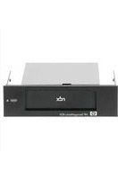

- ACKNOWLEDGMENTS
- CONTENTS
- HPE STOREEASY 1000 STORAGE
- INSTALLING HPE STOREEASY 1000 STORAGE
- CONFIGURING HPE STOREEASY 1000 STORAGE
- MANAGING HPE STOREEASY 1000 STORAGE
- ADMINISTRATION TOOLS
- STORAGE MANAGEMENT OVERVIEW
- FILE SERVER MANAGEMENT
- FEATURES
- HARDWARE COMPONENTS
- HPE STOREEASY 1450 STORAGE HARDWARE COMPONENTS
- HPE STOREEASY 1550 STORAGE HARDWARE COMPONENTS
- HPE STOREEASY 1650 STORAGE HARDWARE COMPONENTS
- HPE STOREEASY 1650 EXPANDED STORAGE HARDWARE COMPONENTS
- SYSTEM BOARD COMPONENTS
- DIMM SLOT LOCATIONS
- SYSTEM MAINTENANCE SWITCH
- NMI FUNCTIONALITY
- HPE STOREEASY 1850 STORAGE HARDWARE COMPONENTS
- DRIVE LED DEFINITIONS
- POWER FAULT LEDS
- FRONT DRIVE THERMAL LED
- SYSTEMS INSIGHT DISPLAY LED COMBINATIONS
- INSTALLING AN M.2 SSD ENABLEMENT BOARD IN THE STOREEASY 1650 EXPANDED STORAGE SYSTEM
- REMOVING AN M.2 SSD ENABLEMENT BOARD FROM THE STOREEASY 1650 EXPANDED SERVER
- SOFTWARE COMPONENTS
- VERIFY THE KIT CONTENTS
- HARDWARE
- LOCATE THE SERIAL NUMBER, CERTIFICATE OF AUTHENTICITY, AND END USER LICENSE AGREEMENT
- INSTALLING THE HPE STOREEASY 1000 STORAGE HARDWARE
- VALIDATE NETWORK INFORMATION
- CABLING HPE STOREEASY 1000 STORAGE
- NOTE
- I/O MODULES
- CABLING GUIDELINES
- SINGLE DOMAIN CABLING DIAGRAMS WITH D6000 DISK ENCLOSURES
- SINGLE DOMAIN CABLING DIAGRAMS WITH D2000/D3000 DISK ENCLOSURES
- DUAL DOMAIN CABLING DIAGRAMS WITH D6000 DISK ENCLOSURES
- DUAL DOMAIN CABLING DIAGRAMS WITH D2000/D3000 DISK ENCLOSURES
- CONNECTING TO HPE STOREEASY 1000 STORAGE
- POWER ON THE SERVER AND LOG ON
- HPE STOREEASY INITIAL CONFIGURATION TASKS
- USING INITIAL CONFIGURATION TASKS
- SYSTEM SETTINGS
- NETWORKING
- NOTIFICATIONS
- STORAGE CONFIGURATION
- PROTECT THIS SERVER
- COMPLETE SYSTEM CONFIGURATION
- USING SERVER CORE MODE
- TRANSITION TO SERVER CORE MODE
- TRANSITION TO SERVER WITH A GUI MODE
- CONFIGURING FAILOVER PROPERTIES FOR MULTI-SITE ENVIRONMENTS
- ADDITIONAL ACCESS METHODS
- USING THE REMOTE DESKTOP METHOD
- USING THE TELNET METHOD
- USING THE NETWORK CONFIGURATION TOOL
- NETWORK INTERFACES
- NETWORK TEAM CONFIGURATION
- NETWORK VLAN CONFIGURATION
- NETWORK INTERFACE IP CONFIGURATION
- NETWORK CONFIGURATION SUMMARY
- NETWORK VALIDATION
- CLICK VALIDATE
- MANAGING THE NETWORK CONFIGURATION FILE
- SAMPLE NETWORK CONFIGURATION FILE
- IMPORTANT
- IMPORTING NETWORK CONFIGURATION
- USING HPE STOREEASY POOL MANAGER
- ACCESSING POOL MANAGER REMOTELY
- CALCULATING POOL SIZE
- POOL MANAGER BEST PRACTICES
- POOL MANAGEMENT BEST PRACTICES
- ARRAY CONFIGURATION BEST PRACTICES
- USING THE HPE SYSTEM DASHBOARD
- VIEWING THE DASHBOARD OVERVIEW
- VIEWING EVENT DETAILS
- CRITICAL
- WARNING
- INFORMATION
- VIEWING STORAGE DETAILS
- OVERVIEW
- DRIVES
- VOLUMES
- SHARES
- VIEWING NETWORK DETAILS
- INTERFACES
- TEAMS
- VLANS
- VIEWING SYSTEM DETAILS
- SOFTWARE
- MANAGING THE DASHBOARD CONFIGURATION FILE
- THRESHOLDS
- OVERRIDES
- SAMPLING
- STORAGE UTILIZATION GRAPH
- STORAGE
- SYSTEM TABS
- EVENT LOGS
- NETWORK
- HPE NOTIFICATION SYSTEM
- MICROSOFT WINDOWS STORAGE SERVER 2012 R2 ADMINISTRATION TOOLS
- REMOTE ADMINISTRATION
- FILE AND STORAGE SERVICES
- DATA DEDUPLICATION
- PRINT MANAGEMENT
- NETWORK FILE SYSTEM USER MAPPING
- STORAGE MANAGEMENT ELEMENTS
- STORAGE MANAGEMENT EXAMPLE
- PHYSICAL STORAGE ELEMENTS
- ARRAYS
- FAULT TOLERANCE
- ONLINE SPARES
- LOGICAL STORAGE ELEMENTS
- LOGICAL DRIVES (LUNS)
- PARTITIONS
- FILE SYSTEM ELEMENTS
- FILE SHARING ELEMENTS
- VOLUME SHADOW COPY SERVICE OVERVIEW
- USING STORAGE ELEMENTS
- FILE SERVICES MANAGEMENT
- STORAGE MANAGEMENT UTILITIES
- ARRAY MANAGEMENT UTILITIES
- HPE SMART STORAGE ADMINISTRATOR
- DISK MANAGEMENT UTILITY
- GUIDELINES FOR MANAGING DISKS AND VOLUMES
- SCHEDULING DEFRAGMENTATION
- DISK QUOTAS
- ADDING STORAGE
- EXPANDING STORAGE
- EXTENDING STORAGE USING WINDOWS STORAGE UTILITIES
- VOLUME SHADOW COPIES
- SHADOW COPY PLANNING
- IDENTIFYING THE VOLUME
- ALLOCATING DISK SPACE
- IDENTIFYING THE STORAGE AREA
- DETERMINING CREATION FREQUENCY
- SHADOW COPIES AND DRIVE DEFRAGMENTATION
- MOUNTED DRIVES
- MANAGING SHADOW COPIES
- ENABLING AND CREATING SHADOW COPIES
- VIEWING A LIST OF SHADOW COPIES
- SET SCHEDULES
- REDIRECTING SHADOW COPIES TO AN ALTERNATE VOLUME
- SHADOW COPIES FOR SHARED FOLDERS
- SMB SHADOW COPIES
- NFS SHADOW COPIES
- RECOVERY OF FILES OR FOLDERS
- RECOVERING A DELETED FILE OR FOLDER
- RECOVERING AN OVERWRITTEN OR CORRUPTED FILE
- RECOVERING A FOLDER
- CLICK EITHER COPY OR RESTORE
- BACKUP AND SHADOW COPIES
- SHADOW COPY TRANSPORT
- TAPE BACKUPS
- DATA MINING
- FOLDER AND SHARE MANAGEMENT
- FOLDER MANAGEMENT
- SHARE MANAGEMENT
- SHARE CONSIDERATIONS
- DEFINING ACCESS CONTROL LISTS
- FILE SERVER RESOURCE MANAGER
- QUOTA MANAGEMENT
- FILE SCREENING MANAGEMENT
- STORAGE REPORTS
- MANAGEMENT TOOLS
- HPE SYSTEMS INSIGHT MANAGER
- MANAGEMENT AGENTS
- TROUBLESHOOTING, SERVICING, AND MAINTENANCE
- MAINTAINING HPE STOREEASY 1000 STORAGE
- DETERMINING THE CURRENT HPE STOREEASY 1000 STORAGE SOFTWARE VERSION
- STARTING THE SYSTEM MANAGEMENT HOMEPAGE APPLICATION
- SYSTEM MANAGEMENT HOMEPAGE MAIN PAGE
- OVERALL SYSTEM HEALTH STATUS
- COMPONENT STATUS SUMMARY
- CONTROLLER
- PHYSICAL DRIVES
- LOGICAL DRIVES
- TAPE DRIVES
- STORAGE BOXES
- SYSTEM
- VERSION CONTROL
- OPERATING SYSTEM
- CERTIFICATE OF AUTHENTICITY
- HPE SYSTEM DASHBOARD
- HPE SYSTEM DASHBOARD DOES NOT LAUNCH OR DISPLAY DATA
- HPE SYSTEM DASHBOARD SERVICES ARE NOT INSTALLED
- MANAGEMENT WEB SERVICES ARE NOT INSTALLED
- HPE SYSTEM DASHBOARD USER INTERFACE IS NOT INSTALLED
- HPE SYSTEM DASHBOARD SERVICE IS PAUSED OR STOPPED
- CPU UTILIZATION IS HIGH CONTINUOUSLY
- KNOWN ISSUES
- VERIFYING SERVICES ARE RUNNING
- ERROR CODES
- STORAGE MANAGEMENT PROVIDER ERROR CODES
- POOL MANAGER PROVIDER ERROR CODES
- MANAGEMENT WEB SERVICE ERROR CODES
- HEWLETT PACKARD ENTERPRISE SUPPORT WEBSITES
- HPE LIVEVAULT
- MICROSOFT SYSTEMS CENTER OPERATIONS MANAGER
- REMOVING AND REPLACING HARDWARE COMPONENTS
- RECOVERING HPE STOREEASY 1000 STORAGE
- SYSTEM RECOVERY DVD
- USING THE SYSTEM RECOVERY DVD TO SAVE SYSTEM DATA
- CREATING A USB FLASH DRIVE WITH AN IMAGE FILE FROM HEWLETT PACKARD ENTERPRISE SOFTWARE DEPOT
- CREATING A DVD WITH AN IMAGE FILE FROM HEWLETT PACKARD ENTERPRISE SOFTWARE DEPOT
- RESTORING THE FACTORY IMAGE WITH A DVD OR USB FLASH DEVICE
- BACKING UP AND RESTORING HPE STOREEASY 1000 STORAGE WITH WINDOWS RECOVERY ENVIRONMENT
- ITERNITY ICAS
- SUPPORT AND OTHER RESOURCES
- ACCESSING HEWLETT PACKARD ENTERPRISE SUPPORT
- INFORMATION TO COLLECT
- ACCESSING UPDATES
- WEBSITES
- CUSTOMER SELF REPAIR
- REMOTE SUPPORT
- DOCUMENTATION FEEDBACK
- A OPERATING SYSTEM LOGICAL DRIVES
- B NETWORK PORTS
- C WARRANTY AND REGULATORY INFORMATION
- WARRANTY INFORMATION
- EAC
- MANUFACTURING DATE
- INDEX
- A
- B
- C
- D
- E
- F
- G
- H
- HPE
- K
- L
- M
- O
- P
- Q
- R
- S
- T
Brand : HP
Model : StoreEasy 1450
Category : Disk array