
RX-6000VBK - Receiver JVC - Free user manual and instructions
Find the device manual for free RX-6000VBK JVC in PDF.


| Product Type | AV Receiver |
| Brand | JVC |
| Model | RX-6000VBK |
| Dimensions (W x H x D) | 435 x 151 x 367 mm |
| Weight | 8.9 kg |
| Power Output (8 ohms, 20Hz-20kHz, 0.08% THD) | 100 W per channel |
| Total Harmonic Distortion | 0.08% |
| Frequency Response | 20 Hz - 20 kHz |
| Inputs | 4 HDMI, 2 Optical, 2 Coaxial, 4 RCA Audio, 1 Phono (MM), 1 Composite Video, 1 Component Video |
| Outputs | 1 HDMI (ARC), 2 Subwoofer Pre-out, 1 Headphone, Speaker Terminals (7.1 channel), 1 Zone 2 Pre-out |
| Supported Audio Formats | Dolby TrueHD, DTS-HD Master Audio, Dolby Digital Plus, DTS 96/24, PCM |
| Wireless Connectivity | Bluetooth 4.2, FM/AM Tuner |
| Power Consumption | 450 W |
| Standby Power Consumption | 0.3 W |
| Voltage | AC 220-240 V, 50/60 Hz |
| Cleaning Instructions | Wipe with a soft dry cloth. Do not use solvents. |
| Safety Instructions | Do not expose to moisture or heat sources. Ensure proper ventilation. Unplug during storms. |
| Spare Parts Availability | Contact JVC support or authorized service centers for replacement parts. |
| Repairability Index | 7.2 / 10 |
| General Information | Supports 4K Ultra HD pass-through, Dolby Vision, HDR10, and HLG. Includes remote control, FM antenna, and setup microphone. |
Frequently Asked Questions - RX-6000VBK JVC
User questions about RX-6000VBK JVC
0 question about this device. Answer the ones you know or ask your own.
Ask a new question about this device
Download the instructions for your Receiver in PDF format for free! Find your manual RX-6000VBK - JVC and take your electronic device back in hand. On this page are published all the documents necessary for the use of your device. RX-6000VBK by JVC.
USER MANUAL RX-6000VBK JVC
For Customer Use:
Enter below the Model No. and Serial No. which are located either on the rear, bottom or side of the cabinet. Retain this information for future reference.
Model No.
Serial No.
Errata Sheet
Please notice the following modifications when reading Instructions.
Page 18.
| Incorrect |
Notes:If “REAR SPK” and “CENTER SPK” are set to “NONE,”— you can select only “HEAD PHONE” or “OFF” for the DSP mode.— you cannot select Surround mode.No sounds come out of the center speaker, even if it is connected. |
| Correct |
| Notes:If “REAR SPK” and “CENTER SPK” are set to “NONE,” you cannot select Surround mode.No sounds come out of the center speaker, even if it is connected.When “REAR SPK” and “CENTER SPK” are set to “NONE,” the same effect as used for the 3D-PHONIC is applied to any DAP mode to maintain the surround elements with only two front speakers. |
Page 20.
On page 20, in the DSP mode cycle it is written that "3D ACTION" will be selected after "HEAD PHONE," but the order has been changed so that "3D ACTION" will be selected before "HEAD PHONE."


The lightning flash with arrowhead symbol, within an equilateral triangle is intended to alert the user to the presence of uninsulated "dangerous voltage" within the product's enclosure that may be of sufficient magnitude to constitute a risk of electric shock to persons.

The exclamation point within an equilateral triangle is intended to alert the user to the presence of important operating and maintenance (servicing) instructions in the literature accompanying the appliance.
WARNING: TO REDUCE THE RISK OF FIRE OR ELECTRIC SHOCK, DO NOT EXPOSE THIS APPLIANCE TO RAIN OR MOISTURE.
Caution — POWER switch!
Disconnect the mains plug to shut the power off completely. The POWER switch in any position does not disconnect the mains line. The power can be remote controlled.
For U.S.A.
This equipment has been tested and found to comply with the limits for a Class B digital device, pursuant to part 15 of the FCC Rules. These limits are designed to provide reasonable protection against harmful interference in a residential installation.
This equipment generates, uses and can radiate radio frequency energy and, if not installed and used in accordance with the instructions, may cause harmful interference to radio communications. However, there is no guarantee that interference will not occur in a particular installation. If this equipment does cause harmful interference to radio or television reception, which can be determined by turning the equipment off and on, the user is encouraged to try to correct the interference by one or more of the following measures:
Reorient or relocate the receiving antenna.
Increase the separation between the equipment and receiver.
Connect the equipment into an outlet on a circuit different from that to which the receiver is connected.
Consult the dealer or an experienced radio/TV technician for help.
CAUTION
To reduce the risk of electrical shocks, fire, etc.:
- Do not remove screws, covers or cabinet.
- Do not expose this appliance to rain or moisture.
Caution: Proper Ventilation
To avoid risk of electric shock and fire and to protect from damage.
Locate the apparatus as follows:
Front: No obstructions, open spacing.
Sides: No obstructions within 10 cm from the sides.
Top: No obstructions in 10 cm from the top
Back: No obstructions in 15 cm from the back
Bottom: Place on the level surface.
In addition, maintain the best possible air circulation as illustrated.

Table of Contents
Parts Identification 2
Getting Started.... 3
Before Installation 3
Checking the Supplied Accessories 3
Connecting the FM and AM Antennas 3
Connecting the Speakers 4
Connecting Audio/Video Components....5
Connecting the Power Cord 7
Putting Batteries in the Remote Control 7
Basic Operations 8
Turning the Power On and Off (Standby) 8
Selecting the Source to Play....8
Adjusting the Volume 9
Selecting the Front Speakers 9
Muting the Sound 9
Adjusting the Subwoofer Output Level.... 10
Attenuating the Input Signal 10
Reinforcing the Bass 10
Adjusting the Tone 10
Basic Settings.... 11
Recording a Source 11
Adjusting the Front Speaker Output Balance.... 11
Setting the Subwoofer Information 11
Changing the Source Name.... 11
Setting the Speakers for the DSP Modes 12
Digital Input (DIGITAL IN) Terminal Setting 14
Selecting the Analog or Digital Input Mode 14
Storing the Basic Settings and Adjustments — One Touch Operation .... 15
Using the Sleep Timer 15
Receiving Radio Broadcasts 16
Tuning in Stations Manually 16
Using Preset Tuning 16
Selecting the FM Reception Mode.... 17
Using the DSP Modes 18
Available DSP Modes According to the Speaker Arrangement .. 20
Adjusting the 3D-PHONIC Modes ...... 21
Adjusting the DAP Modes and Headphones mode 21
Adjusting the Surround Modes 22
Activating the DSP Modes 25
COM PU LINK Remote Control System ...... 26
AV COMPU LINK Remote Control System .... 27
Operating JVC's Audio/Video Components ... 29
Troubleshooting 31
Specifications.... 32
Become familiar with the buttons and controls on the receiver before use. Refer to the pages in parentheses for details.


Front Panel
1 POWER button and STANDBY lamp (8) ② SOURCE NAME (TV SOUND/DBS) button (11) ③ Display (8) 4 ONE TOUCH OPERATION/INPUT ATT. button (15) ⑤ DSP MODE button (21) 6 SURROUND button and lamp (25) ⑦ Remote sensor (7) ⑧ ADJUST button (10) * ⑨ SETTING button (12 - 14) * 10 MASTER VOLUME control (9) ⑪ MEMORY button (16) ⑫ MULTI CURSOR buttons ⑬ ANALOG/DIGITAL button and DIGITAL AUTO lamp (14) 14 Source selecting buttons (8) DVD, TV SOUND/DBS, VCR, CD, TAPE/MD, PHONO, FM/AM * 15 SOURCE NAME (TAPE/MD) button (8, 11, 14) 16 SPEAKERS 1/2 buttons (9) 17 PHONES jack (9)
Remote Control
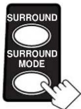
① POWER buttons (8, 30) TV, VCR, AUDIO ② SLEEP button (15) 3 SURROUND button (25) 4 SURROUND MODE button (21) ⑤ SOUND button (21) ⑥ TV/VIDEO button (30) ⑦ CD-DISC button (29) 8 Source selecting buttons (8) DVD, TV SOUND/DBS, VCR, CD, TAPE/MD, PHONO, FM/AM ⑨ TV VOL +/- buttons (30) ⑩ TV CH +/- buttons (30) ⑪ • 10 keys for selecting preset channel (17) • 10 keys for adjusting sound (22 – 24, 29) • 10 keys for operating audio/video components (29, 30) ⑫ ANALOG/DIGITAL button (14) ⑬ MUTING button (9) 14 VOLUME +/- buttons (9) 15 Operating buttons for audio/video components (29, 30)
IMPORTANT:
To use the MULTI CURSOR buttons (12) on the front panel:
What these buttons actually do depends on which function you are trying to adjust. Before using these buttons, select the function by pressing one of the buttons marked with *.
This section explains how to connect audio/video components and speakers to the receiver, and how to connect the power supply.
Before Installation
General
- Be sure your hands are dry.
- Turn the power off to all components.
- Read the manuals supplied with the components you are going to connect.
Locations
• Install the receiver in a location that is level and protected from moisture. - The temperature around the receiver must be between -5°C and 35°C (23°F and 95°F). - Make sure there is good ventilation around the receiver. Poor ventilation could cause overheating and damage the receiver.
Handling the receiver
- Do not insert any metal object into the receiver.
- Do not disassemble the receiver or remove screws, covers, or cabinet.
- Do not expose the receiver to rain or moisture.
Checking the Supplied Accessories
Check to be sure you have all of the following items, which are supplied with the receiver. The number in the parentheses indicates the quantity of the pieces supplied.
- Remote Control (1)
- Batteries (2) • AM Loop Antenna (1)
- FM Antenna (1)
If anything is missing, contact your dealer immediately.
Connecting the FM and AM Antennas
FM Antenna Connections
A. Using a Supplied FM Antenna The FM antenna provided can be connected to the FM 75Ω COAXIAL terminal as a temporary measure.
B. Using a Standard Type Connector (Not Supplied)
A standard type connector should be connected to the FM 75Ω COAXIAL terminal.
Note:
If reception is poor, connect an outdoor antenna. Before attaching a 75Ω coaxial cable (the kind with a round wire going to an outdoor antenna), disconnect the supplied FM antenna.
AM Antenna Connections
Turn the loop antenna until you have the best reception.
Notes:
- Make sure the antenna conductors do not touch any other terminals, connecting cords, and power cord. This could cause poor reception.
- If reception is poor, connect an outdoor single vinyl-covered wire to the AM EXT terminal. (Keep the AM loop antenna connected.)
Connecting the Speakers
You can connect the following speakers:
- Two pairs of front speakers to produce normal stereo sound. • One pair of rear speakers to enjoy the surround effect. • One center speaker to produce more effective surround effect (to emphasize human voices).
- One subwoofer to enhance the bass.
IMPORTANT:
After connecting the speakers listed above, set the speaker setting information properly to obtain the best possible DSP effect. For details, see page 12.
For each speaker (except for a subwoofer), connect the (-) and (+) terminals on the rear panel to the (-) and (+) terminals marked on the speakers. For connecting a subwoofer, see page 5.
CAUTION:
Use speakers with the SPEAKER IMPEDANCE indicated by the speaker terminals.
Basic connecting procedure
1 Cut, twist and remove the insulation at the end of each speaker signal cable (not supplied). 2 Open the terminal and then insert the speaker signal cable. 3 Close the terminal.
Connecting the front speakers
You can connect two pairs of front speakers (one pair to the FRONT SPEAKERS ① terminals, and another pair to the FRONT SPEAKERS ② terminals).
Right speaker — FRONT SPEAKERS ① — Left speaker

Connecting the rear and center speakers
Connect rear speakers to the REAR SPEAKERS terminals and a center speaker to the CENTER SPEAKER terminals.

Connecting the subwoofer speaker
You can enhance the bass by connecting a subwoofer.
Connect the input jack of a powered subwoofer to the
SUBWOOFER OUT jack on the rear panel, using a cable with RCA pin plugs (not supplied).

Powered subwoofer
Connecting Audio/Video Components
You can connect the following audio/video components to this receiver. Refer also to the manuals supplied with your components.
| Audio Components Video Components | |
| • CD player* • DVD player* | |
| • Turntable • TV | |
| • Cassette deck • DBS tuner* or MD recorder* • VCR | |
* You can connect these components using the methods described in "Analog connections" (below) or in "Digital connections" (see page 7).
Analog connections
Audio component connections
Use the cables with RCA pin plugs (not supplied).
Connect the white plug to the audio left jack, and the red plug to the audio right jack.
CAUTION:
If you connect a sound-enhancing device such as a graphic equalizer between the source components and this receiver, the sound output through this receiver may be distorted.


Note:
Any turntables incorporating a small-output cartridge such as an MC (moving-coil type) must be connected to this receiver through a commercial head amplifier or step-up transformer. Direct connection may result in insufficient volume.
Cassette deck or MD recorder![graph TD A["Cassette deck"] -->|To audio input| B["MD recorder"] B -->|To audio output| C["To audio output"] A --> D["TV SOUND /DBS"] A --> E["OUT (REC)"] A --> F["VCR IN (PLAY)"] A --> G["OUT (REC)"] A --> H["TAPE"] A --> I["MD IN (PLAY)"] A --> J["RIGHT LEFT"] B --> K["To audio output"] B --> L["T…](/content/2026/06/1313398/images/ab4f52383890e251c1456e2163c225ec84209c006594b9b691d1ba16a57bcd9e.jpg)
Note:
You can connect either a cassette deck or an MD recorder to the TAPE/MD jacks. When connecting an MD recorder to the TAPE/MD jacks, change the source name, which will be shown on the display when selected as the source, to "M D." See page 11 for details.
If your audio components have a COMPU LINK-3 terminal
See also page 26 for detailed information about the connection and the COMPU LINK-3 remote control system.
Video component connections
Use the cables with RCA pin plugs (not supplied).
Connect the white plug to the audio left jack, the red plug to the audio right jack, and the yellow plug to the video jack.
IMPORTANT:
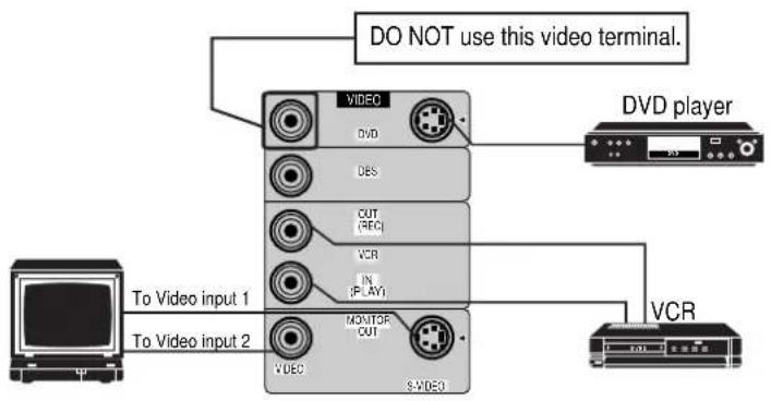
This receiver is equipped with both the composite video and S-video input terminals for the DVD player connection.
You do not have to connect both the composite video and S-video terminals.
However, remember that the video signals from the composite video input terminal are output only through the composite video output terminals, while the ones from the S-video input terminal are output only through the S-video output terminal.
Therefore, if your DVD player is connected to the receiver only through the S-video input terminal, you cannot record the picture from the DVD player on the VCR.
In addition, if the TV and the DVD player are connected to the receiver through the different video terminals, you cannot view the playback picture from the DVD player on the TV.

A To front left/right channel audio output (or to audio mixed output if necessary) B To composite video output C To S-video output (for better playback picture quality)
![graph TD A["VCR"] --> B["VD"] B --> C["Digital 1 (CVD)"] B --> D["Digital 2 (CD)"] B --> E["Digital 3 (CTS)"] B --> F["Digital 4 (N)"] B --> G["Digital 5 (LPG)"] B --> H["Digital 6 (PSY)"] B --> I["Digital 7 (PSY)"] B --> J["Digital 8 (PSY)"] B --> K["Digital 9 (PSY)"] B --> L["Digital 10 (PSY)"] B…](/content/2026/06/1313398/images/54fb0b4023f42d7253a7fe0acca4aed2b2aa994482882de30f47d89f65f6c9f0.jpg)
A To left/right channel audio output B To left/right channel audio input C To composite video output D To composite video input
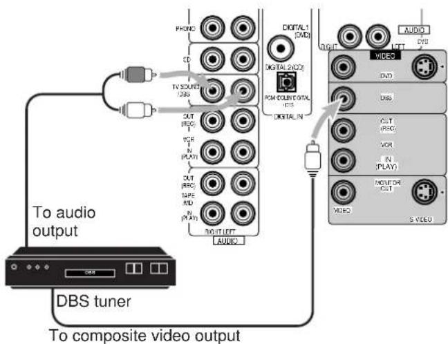
TV and/or DBS tuner
When connecting the TV to the TV SOUND/DBS jacks, do not connect the TV's video output to the video input terminal.
![graph TD A["TV"] -->|To audio output| B["Monitor"] B --> C["COMPOSITE VIDEO INPUT TO S-VIDEO INPUT (FOR BEETTER PLAYBACK PICTURE QUALITY)"] C --> D["Connect the TV to the MONITOR OUT jack to view the playback picture from the other connected video components."] style A fill:#f9f,stroke:#333 style B…](/content/2026/06/1313398/images/074afcc753c31e49437c4e2295e6b00bb1973ce87ff2145232417015ab73a6be.jpg)
Note:
When connecting the DBS tuner to the TV SOUND/DBS jacks, change the source name, which will be shown on the display when selected as the source, to "DBS." See page 11 for details.
If your audio components have an AV COMPU LINK terminal, see also page 27 for detailed information about the connection and the AV COMPU LINK remote control system.
Digital connections
This receiver is equipped with two DIGITAL IN terminals — one digital coaxial terminal and one digital optical terminal.
You can connect any component to one of the digital terminals using a digital coaxial cable (not supplied) or digital optical cable (not supplied).
IMPORTANT:
- When connecting the DVD player or the DBS tuner using the digital terminal, you also need to connect it to the video jack on the rear. Without connecting it to the video jack, you can view no playback picture.
- After connecting the components using the DIGITAL IN terminals, set the following correctly if necessary.
- Set the digital input (DIGITAL IN) terminal setting correctly. For details, see "Digital Input (DIGITAL IN) Terminal Setting" on page 14.
- Select the digital input mode correctly. For details, see "Selecting the Analog or Digital Input Mode" on page 14.


When the component has a digital coaxial output terminal, connect it to the DIGITAL 1 (DVD) terminal, using a digital coaxial cable (not supplied).
When the component has a digital optical output terminal, connect it to the DIGITAL 2 (CD), using a digital optical cable (not supplied).
Before connecting a digital optical cable, unplug the protective plug.

Notes:
- When shipped from the factory, the DIGITAL IN terminals have been set for use with the following components.
- DIGITAL 1 (coaxial): For DVD player
- DIGITAL 2 (optical): For CD player
- When you want to operate the CD player or MD recorder using the COMPU LINK remote control system, connect the target component also as described in "Analog connections" (see page 5).
- When you want to operate the DVD player using the AV COMPU LINK remote control system, connect the DVD player also as described in "Analog connections" (see page 5).
Connecting the Power Cord
Before plugging the receiver into an AC outlet, make sure that all connections have been made.
Plug the power cord into an AC outlet.
Keep the power cord away from the connecting cables and the antenna. The power cord may cause noise or screen interference. We recommend that you use a coaxial cable to connect the antenna, since it is well-shielded against interference.

Note:
The preset settings such as preset channels and sound adjustment may be erased in a few days in the following cases:
- When you unplug the power cord.
- When a power failure occurs.
CAUTIONS:
- Do not touch the power cord with wet hands.
- Do not pull on the power cord to unplug the cord. When unplugging the cord, always grasp the plug so as not to damage the cord.
Putting Batteries in the Remote Control
Before using the remote control, put two supplied batteries first. When using the remote control, aim the remote control directly at the remote sensor on the receiver.


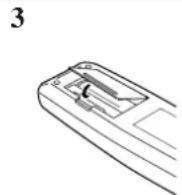
- On the back of the remote control, remove the battery cover.
- Insert batteries. Make sure to match the polarity: (+) to (+) and (-) to (-).
- Replace the cover.
If the range or effectiveness of the remote control decreases, replace the batteries. Use two R6P(SUM-3)/AA(15F) type dry-cell batteries.
CAUTION:
Follow these precautions to avoid leaking or cracking cells:
- Place batteries in the remote control so they match the polarity: (+) to (+) and (−) to (−).
- Use the correct type of batteries. Batteries that look similar may differ in voltage. • Always replace both batteries at the same time.
- Do not expose batteries to heat or flame.
The following operations are commonly used when you play any sound source.
Turning the Power On and Off (Standby)
On the front panel:
To turn on the power, press POWER. The STANDBY lamp goes off. The name of the current source (or station frequency) appears on the display.

Current source name appears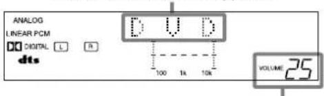
Current volume level is shown here
To turn off the power (into standby mode), press POWER again.
The STANDBY lamp lights up. A small amount of power is consumed in standby mode. To turn the power off completely, unplug the AC power cord.

From the remote control:
To turn on the power, press AUDIO POWER. The STANDBY lamp goes off. The name of the current source (or station frequency) appears on the display.

To turn off the power (into standby mode), press AUDIO POWER again.
The STANDBY lamp lights up.
Selecting the Source to Play
Press one of the source selecting buttons.
On the front panel:

From the remote control:
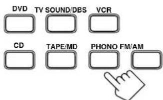

DVD: Select the DVD player for viewing the stereo digital video disc.
TV SOUND/DBS: Select the TV sound (or the DBS tuner).
VCR: Select the video component connected to the VCR jacks.
CD: Select the CD player.
TAPE/MD: Select the cassette deck (or the MD recorder).
PHONO: Select the turntable.
FM/AM: Select an FM or AM broadcast.
• Each time you press the button, the band alternates between FM and AM.
Notes:
- When connecting an MD recorder (to the TAPE/MD jacks) or a DBS tuner (to the TV SOUND/DBS jacks), change the source name that appears on the display. See page 11 for details.
- When you press one of the source selecting buttons on the remote control marked above with an asterisk (*), the receiver automatically turns on.
Signal and speaker indicators on the display
- The signal indicators light up to indicate the incoming channel signals.
- Only the indicators for the incoming signals light up. (When analog input is selected, "L" and "R" always light up.)
- The frame of the signal indicator (except for "LFE": See notes below) lights up if the corresponding speaker is set to "LARGE" or "SMALL" (for subwoofer, "YES").

L: Lights up when the left front channel signal comes in. The frame of this signal indicator always lights up.
R: Lights up when the right front channel signal comes in. The frame of this signal indicator always lights up.
C: Lights up when the center channel signal comes in.
LS: Lights up when the left rear channel signal comes in.
RS: Lights up when the right rear channel signal comes in.
S: Lights up when the monaural rear channel signal comes in.
LFE: Lights up when the LFE channel signal comes in.
Notes:
- When the LFE channel signal comes in, "LFE" lights up.
- When "SUBWOOFER" is set to "YES," (See page 15) SUBWFR lights up.
Selecting different sources for picture and sound
You can watch picture from a video component while listening to sound from another component. Press one of the audio source selecting buttons (CD, TAPE/MD, PHONO, FM/AM, TV SOUND*), while viewing the picture from a video component such as the VCR or DVD player, etc.
On the front panel:
![graph TD A["TV SOUND/DBS"] --> B["SOURCE NAME"] C["CD"] --> D["TAPE-MD"] E["SOURCE NAME"] --> F["PHONO"] G["FMHAM"] --> H["FMHAM"]](/content/2026/06/1313398/images/b8d78a474dbde070e43ff1cde18a084dc80db287857486d7a42dfa0465977f69.jpg)
From the remote control:

Notes:
- Once you have selected a video source, pictures of the selected source are sent to the TV until you select another video source. * Except when your TV is connected through the AV COMPU LINK remote control system (see page 27).
Adjusting the Volume
On the front panel:
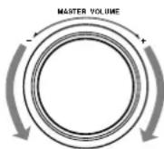
To increase the volume, turn MASTER VOLUME clockwise.
To decrease the volume, turn it counterclockwise.
- When you turn MASTER VOLUME rapidly, the volume level also changes rapidly.
- When you turn MASTER VOLUME slowly, the volume level also changes slowly.
From the remote control:
To increase the volume, press VOLUME +. To decrease the volume, press VOLUME -.

CAUTION:
Always set the volume to the minimum before starting any source. If the volume is set at its high level, the sudden blast of sound energy can permanently damage your hearing and/or ruin your speakers.
Note:
The volume level can be adjusted within the range of "0" (minimum) to "80" (maximum).
Selecting the Front Speakers
On the front panel ONLY:
When you have connected two pairs of front speakers, you can select which to use. Pressing SPEAKERS 1 or SPEAKERS 2 activates the respective set of speakers.
- To use the speakers connected to the FRONT SPEAKERS ① terminals, press SPEAKERS 1 to set it to the ON position, and press SPEAKERS 2 to set it to the OFF position.
- To use the speakers connected to the FRONT SPEAKERS ② terminals, press SPEAKERS 2 to set it to the ON position, and press SPEAKERS 1 to set it to the OFF position.
- To use both sets of speakers, press SPEAKERS 1 and SPEAKERS 2 to set them to the ON position.
- To use neither set of speakers, press SPEAKERS 1 and SPEAKERS 2 to set them to the OFF position.
Note:
When only one set of speakers is connected to either the FRONT SPEAKERS ① or ② terminals, do not activate both pairs of speakers. If you do, no sound will come out of the front speakers.
Listening only with headphones
- Connect a pair of headphones to the PHONES jack on the front panel.
- Press SPEAKERS 1 and SPEAKERS 2 to set them to the OFF position.
CAUTION:
Be sure to turn down the volume before connecting or putting on the headphones, as high volume can damage both the headphones and your hearing.
Note:
You cannot shut off the sound through the other speakers using the SPEAKERS 1 and 2 buttons.
Muting the Sound
From the remote control ONLY:
Press MUTING to mute the sound through all speakers and headphones connected.
"MUTING" appears on the display and the volume turns off (the volume level indicator goes off).

To restore the sound, press MUTING again so that "OFF" appears on the display.
- Turning MASTER VOLUME or pressing VOLUME +/- also restores the sound.
Adjusting the Subwoofer Output Level
You can adjust the subwoofer output level if you have selected "YES" for the "SUBWOOFER" (see page 11).
Once it has been adjusted, the receiver memorizes the adjustment.
Before you start, remember...
- There is a time limit in doing the following steps. If the setting is canceled before you finish, start from step 1 again.
On the front panel:
- Press ADJUST repeatedly until "SUBWFR LEVEL" appears on the display.

- Once you have pressed ADJUST, MULTI CURSOR ▲/▼ can be also used for selecting "SUBWFR LEVEL."
- The display changes to show the current setting.
- Press MULTI CURSOR ◀/▶ to adjust the subwoofer output level (-10 dB to +10 dB).

From the remote control:
- Press SOUND.
The 10 keys are activated for sound adjustments.

- Press SUBWOOFER -/+ to adjust the subwoofer output level (-10 dB to +10 dB).

Attenuating the Input Signal
When the input level of the playing source is too high, the sounds will be distorted. If this happens, you need to attenuate the input signal level to prevent the sound distortion.
On the front panel ONLY:
Press and hold INPUT ATT. (ONE TOUCH OPERATION) so that the ATT indicator lights up on the display.

- Each time you press and hold the button, the Input Attenuator mode turns on (“INPUT ATT ON”) or off (“INPUT NORMAL”).
Notes:
- This function is available only for the sources connected using the analog terminals.
- This function does not take effect when digital input is selected.
Reinforcing the Bass
With this Bass Boost function, you can boost the bass level.
Before you start, remember...
- There is a time limit in doing the following steps. If the setting is canceled before you finish, start from step 1 again.
On the front panel ONLY:
- Press ADJUST repeatedly until "BASSBOOST" (with the current setting) appears on the display.

- Once you have pressed ADJUST, MULTI CURSOR / can be also used for selecting "BASSBOOST."
- Press MULTI CURSOR ◀/▷ to switch this function “ON” or “OFF.”
- When this function is switched “ON,” the BASS BOOST indicator on the display lights up.

Note:
The Bass Boost function affects the front speaker sounds only.
Adjusting the Tone
You can adjust the treble and bass sounds as you like.
Before you start, remember...
- There is a time limit for completing the following steps. If the setting is canceled before you finish, start again from step 1.
On the front panel ONLY:
- Press ADJUST repeatedly until "BASS" or "TREBLE" appears on the display.

- Once you have pressed ADJUST, MULTI CURSOR ▲/▼ can also be used to select "BASS" or "TREBLE."
- Select "BASS" to adjust the bass sound level.
- Select "TREBLE" to adjust the treble sound level.
- Press MULTI CURSOR ◀/▶ to adjust the bass or treble sound level within the range of -10 to +10.
• Each time you press the button, the sound level changes by ±2 steps.

Some of the following settings are required after connecting and positioning your speakers in your listening room, while others will make operations easier.
Recording a Source
You can record any source playing through the receiver to a cassette deck (or an MD recorder) connected to the TAPE/MD jacks and the VCR connected to the VCR jacks at the same time.
While recording, you can listen to the selected sound source at whatever sound level you like, without affecting the sound levels of the recording.
Note:
The output volume level, tone adjustment (see page 10), bass boost (see page 10) and DSP modes (see page 18) cannot affect the recording.
Adjusting the Front Speaker Output Balance
If the sounds you hear from the front right and left speakers are unequal, you can adjust the speaker output balance.
Before you start, remember...
- There is a time limit in doing the following steps. If the setting is canceled before you finish, start from step 1 again.
On the front panel ONLY:
- Press ADJUST repeatedly until "L/R BALANCE" appears on the display.

- Once you have pressed ADJUST, MULTI CURSOR / can be also used for selecting "L/R BALANCE."
- Press MULTI CURSOR / to adjust the balance.
- Pressing decreases the right channel output (from "L-21" to "R-21").
- Pressing decreases the left channel output (from "R-21" to "L-21").

Setting the Subwoofer Information
Register whether or not you have connected a subwoofer.
Before you start, remember...
- There is a time limit in doing the following steps. If the setting is canceled before you finish, start from step 1 again.
On the front panel ONLY:
- Press SETTING repeatedly until "SUBWOOFER" appears on the display.

- Once you have pressed SETTING, MULTI CURSOR ▲/▼ can also be used for selecting "SUBWOOFER."
- The display changes to show the current setting.
- Press MULTI CURSOR ◀/▶ to select "YES" or "NO."

YES: Select this when a subwoofer is used.
NO: Select this when no subwoofer is used.
Changing the Source Name
When you have connected the MD recorder to the TAPE/MD jacks or the DBS tuner to the TV SOUND/DBS jacks on the rear panel, change the source name shown on the display when you select the MD recorder or the DBS tuner as the source.
On the front panel ONLY:
When changing the source name from "TAPE" to "MD":
- Press TAPE/MD.
- Make sure "TAPE" appears on the display.

- Press and hold SOURCE NAME (TAPE/MD) until "ASSGN. MD" appears on the display.
To change the source name from "MD" to "TAPE," repeat the same procedure above (in step 1, make sure "MD" appears on the display).
When changing the source name from "TV SOUND" to "DBS":
- Press TV SOUND/DBS.
- Make sure “TV SOUND” appears on the display.

- Press and hold SOURCE NAME (TV SOUND/DBS) until "ASSGN. DBS" appears on the display.
To change the source name from “DBS” to “TV SOUND,” repeat the same procedure above (in step 1, make sure “DBS” appears on the display).
Note:
Without changing the source name, you can still use the connected components. However, there may be some inconvenience.
- “TAPE” or “TV SOUND” will appear on the display when you select the MD recorder or DBS tuner.
- You cannot select the digital input (see page 14) for the MD recorder and the DBS tuner.
- You cannot use the COMPU LINK remote control system (see page 26) to operate the MD recorder.
Setting the Speakers for the DSP Modes
To obtain the best possible surround sound of the DSP (Digital Signal Processor) modes (see page 18), you have to register the information about the speakers arrangement after all connections are completed.
Before you start, remember...
- There is a time limit in doing the following steps. If the setting is canceled before you finish, start from step 1 again.
Front, Center, and Rear Speaker Setting
Register the sizes of all the connected speakers.
On the front panel ONLY:
- Press SETTING repeatedly until "FRONT SPK" (Front Speaker), "CENTER SPK" (Center Speaker), or "REAR SPK" (Rear Speaker) appears on the display.
- Once you have pressed SETTING, MULTI CURSOR ▲/▼ can also be used for selecting the speakers.

- Press MULTI CURSOR ◀/▶ to select the appropriate item about the speaker selected in the above step.


LARGE: Select this when the speaker size is relatively large.
SMALL: Select this when the speaker size is relatively small.
NONE: Select this when you have not connected a speaker. (Not selectable for the front speakers)
3. Repeat steps 1 and 2 to select the appropriate items for the other speakers.
Notes:
- Keep the following comment in mind as reference when adjusting.
- If the size of the cone speaker unit built in your speaker is greater than 12 cm, select "LARGE," and if it is smaller than 12 cm, select "SMALL."
- If you have selected "NO" for the subwoofer setting, you can only select "LARGE" for the front speaker setting.
- If you have selected "SMALL" for the front speaker setting, you cannot select "LARGE" for the center and rear speaker settings.
- When you change your speakers, you need to register the information about the speaker again.
Center Delay Time Setting
Register the delay time of the sound from the center speaker, comparing that of the sound from the front speakers. If the distance from your listening point to the center speaker is equal to that to the front speakers, select 0 msec. As the distance to the center speaker becomes shorter, increase the delay time.
- 1 msec increase (or decrease) in delay time corresponds to 30 cm decrease (or increase) in distance.
- When shipped from the factory, delay time is set to 0 msec.
On the front panel ONLY:
- Press SETTING repeatedly until "CENTER DELAY" appears on the display.

- Once you have pressed SETTING, MULTI CURSOR △/▽ can be also used for selecting "CENTER DELAY."
- The display changes to show the current setting.
- Press MULTI CURSOR ◁/▷ to select the delay time of the center speaker output.

- Pressing ▷ increases the delay time from 0 msec ("C. DELAY: 0ms") to 5 msec ("C. DELAY: 5ms").
- Pressing ◁ decreases the delay time from 5 msec ("C. DELAY: 5ms") to 0 msec ("C. DELAY: 0ms").
Rear Delay Time Setting
Register the delay time of the sound from the rear speakers, comparing that of the sound from the front speakers. If the distance from your listening point to the rear speakers is equal to that to the front speakers, select 0 msec. As the distance to the rear speakers becomes shorter, increase the delay time.
- 1 msec increase (or decrease) in delay time corresponds to 30 cm decrease (or increase) in distance.
- Rear delay time for Dolby Digital and DTS Digital Surround is to be set to 5 msec.
- When shipped from the factory, delay time is set to 5 msec.
On the front panel ONLY:
- Press SETTING repeatedly until "REAR DELAY" appears on the display.

- Once you have pressed SETTING, MULTI CURSOR ▲/▼ can be also used for selecting "REAR DELAY."
- The display changes to show the current setting.
- Press MULTI CURSOR ◀/▶ to select the delay time of the rear speaker output.

- Pressing ▶ increases the delay time from 0 msec ("R. DELAY: 0ms") to 15 msec ("R. DELAY: 15ms").
- Pressing ◀ decreases the delay time from 15 msec (“R. DELAY: 15ms”) to 0 msec (“R. DELAY: 0ms”).
Crossover Frequency Setting
Small speakers cannot reproduce the bass sound very well. So, if you have used a small speaker for any of the front, center, or rear channels, this receiver automatically reallocates the bass elements, originally assigned to the channel for which you have connected the small speaker, to another channel (for which you have connected the large speaker).
If you have selected “LARGE” for all speakers (see page 12), this function will not take effect. To use this function properly, you need to set this crossover frequency level according to the size of the small speaker connected.
This function takes effect in the following cases:
- When playing a source using Dolby Pro Logic, Dolby Digital, or DTS Digital Surround.
- When using the DAP modes.
On the front panel ONLY:
1. Press SETTING repeatedly until "CROSSOVER FRQ" (Crossover Frequency) appears on the display.

- Once you have pressed SETTING, MULTI CURSOR ▲/▼ can be also used for selecting "CROSSOVER FRQ."
- The display changes to show the current setting.
2. Press MULTI CURSOR ◀/▶ to select the crossover frequency level according to the size of the small speaker connected.

- As you press it, the display changes to show the following:

- Use the following comments as reference when adjusting. 80Hz: Select this when the cone speaker unit built in the speaker is about 12 cm. 100Hz: Select this when the cone speaker unit built in the speaker is about 10 cm. 120Hz: Select this when the cone speaker unit built in the speaker is about 8 cm.
Low Frequency Effect Attenuator Setting
If the bass sound is distorted while playing back a source using Dolby Digital or DTS Digital Surround, follow the procedure below.
- This function takes effect only when the subwoofer (LFE) signals come in. (with "SUBWOOFER" set to "Yes.")
On the front panel ONLY:
1. Press SETTING repeatedly until "LFE ATT" (Low Frequency Effect Attenuator) appears on the display.

- Once you have pressed SETTING, MULTI CURSOR ▲/▼ can also be used for selecting "LFE ATT."
- The display changes to show the current setting.
2. Press MULTI CURSOR ◀/▶ to select the low frequency effect attenuator level.
- As you press it, the display changes to show the following:

0dB 10dB→
0dB: Normally select this.
10dB: Select this when the bass sound is distorted.
Dynamic Range Compression Setting
You can compress the dynamic range (difference between maximum sound and minimum sound) of the reproduced sound. This is useful when enjoying surround sound at night.
- This function takes effect only when playing back a source using Dolby Digital.
On the front panel ONLY:
1. Press SETTING repeatedly until "D. RANGE COMP." (Dynamic Range Compression) appears on the display.

- Once you have pressed SETTING, MULTI CURSOR ▲/▼ can also be used for selecting "D. RANGE COMP."
- The display changes to show the current setting.
2. Press MULTI CURSOR ◀/▶ to select the appropriate item about the compression level.
As you press it, the display changes to show the following:


| OFF: | Select this when you want to enjoy surround with its full dynamic range. (No effect applied) |
| MID: | Select this when you want to reduce the dynamic range a little. (Factory setting) |
| MAX: | Select this when you want to apply the compression effect fully. (Useful at night) |
Digital Input (DIGITAL IN) Terminal Setting
When using the digital input terminals, you must register which components are connected to which terminals (DIGITAL IN 1/2).
Before you start, remember...
- There is a time limit for performing the following steps. If the setting is canceled before you finish, start again from step 1.
On the front panel ONLY:
1. Press SETTING repeatedly until "DIGITAL IN" appears on the display.

- Once you have pressed SETTING, MULTI CURSOR △/▽ can also be used to select "DIGITAL IN."
- The display changes to show the current setting.
DIGITAL 2 terminal setting
DIGITAL 1 terminal setting
2. Press MULTI CURSOR ◀/▷ to select an appropriate setting.
- As you press it, the display changes to show the following:

1 DVD 2 CD ⇌ 1 DVD 2 DBS ⇌ 1 DVD 2 MD ⇌
1 CD 2 DVD ⇌ 1 CD 2 DBS ⇌ 1 CD 2 MD ⇌
1 DBS 2 DVD ⇌ 1 DBS 2 CD ⇌ 1 DBS 2 MD ⇌
1 MD 2 DVD ⇌ 1 MD 2 CD ⇌ 1 MD 2 DBS ⇌
(back to the beginning)
Note:
When shipped from the factory, the DIGITAL IN terminals can be used as the digital input for the following components.
• DIGITAL 1 (coaxial): For DVD player • DIGITAL 2 (optical): For CD player
Selecting the Analog or Digital Input Mode
When you have connected some digital source components using the digital terminals (see page 7), you need to change the input mode for these components to the appropriate digital input mode correctly — AUTO/PCM, DOLBY DIGITAL, or DTS.
Once the correct mode is selected for each digital source component, the mode is memorized until you change it.
- Follow the steps in "Digital Input (DIGITAL IN) Terminal Setting" to the left.
- Press the source selecting button (CD, TAPE/MD, TV SOUND/DBS, or DVD) for which you want to change the input mode from analog input to digital input.

On the front panel
On the remote control
3. Press ANALOG/DIGITAL repeatedly until the digital input mode you want appears on the display.
On the front panel
On the remote control
Each time you press the button, the input mode changes as follows:
![graph LR A["ANALOG"] --> B["AUTO/PCM (Digital)"] B --> C["DOLBY DIGITAL (Digital)"] C --> D["DT S (Digital)"] D --> A](/content/2026/06/1313398/images/c781cdeaf9b4d0a3ffe385be0a2c8fd7714466701a0b7af09264861f4fabe780.jpg)
Normally select “AUTO/PCM,” so the receiver automatically detects the incoming digital signal. The DIGITAL AUTO indicator lights up on the display. (The DIGITAL AUTO lamp next to the ANALOG/DIGITAL button lights up.)
- When the receiver can recognize the digital signal coming into the receiver, the frame of the digital signal indicator for the detected signal lights up automatically.
- When the receiver cannot recognize the incoming signal correctly, the frame of the digital signal indicator flashes. If this happens, select the same digital input mode with the incoming digital signal — either “DOLBY DIGITAL” or “DTS.”
Notes:
- Noise may come out of the speakers while searching or skipping a multi-sound source encoded with Dolby Digital or DTS Digital Surround. If this happens, select "DOLBY DIGITAL" or "DTS" for digital input mode. (See above)
- When you change the source, the digital input mode will be automatically reset to "AUTO/PCM."
Storing the Basic Settings and Adjustments — One Touch Operation
JVC's One Touch Operation function is used to assign and store different sound settings for each different playing source. By using this function, you do not have to change the settings every time you change the source. The stored settings for the newly selected source are automatically recalled.
The following can be stored for each source:
• Volume level (see page 9) • Bass boost (see page 10) • Tone adjustment (see page 10) • Input attenuator mode (see page 10) • Subwoofer output level (see page 10) • Balance (see page 11) • DSP modes • 3D-PHONIC mode settings (see page 21) • DAP mode settings (see page 21) • Surround mode settings (see page 22)
On the front panel ONLY:
To store the sound settings
- Press ONE TOUCH OPERATION (INPUT ATT.) so that the ONE TOUCH OPERATION indicator lights up on the display.

2. Adjust the sound using the functions listed above.
The newly adjusted settings are memorized.
To recall the sound settings
With the ONE TOUCH OPERATION lamp lit, the settings for the currently selected source are recalled when the source is selected.
To cancel the One Touch Operation function
Press ONE TOUCH OPERATION (INPUT ATT.) so that the ONE TOUCH OPERATION indicator goes off.
(Even though the One Touch Operation function is canceled, the recalled sound effects remain active.)
Note:
If the source is FM or AM, you can assign a different setting for each band.
Using the Sleep Timer
Using the Sleep Timer, you can fall asleep to music and know the receiver will turn off by itself rather than play all night.
From the remote control ONLY:
Press SLEEP repeatedly.
The SLEEP indicator lights up on the display, and the shut-off time changes as follows (in minutes):

![graph LR A["→ 2010 30-40 50-60 70 80 90"] --> B["→"] B --> C["00 (Canceled)"] C --> D["→"]](/content/2026/06/1313398/images/6bfa3e664465d76289f66926320f2f8510809b663efe7431795331eb3eff39b4.jpg)
When the shut-off time comes
The receiver turns off automatically.
To check or change the time remaining until the shut-off time Press SLEEP once.
The remaining time until the shut-off time appears in minutes.
- To change the shut-off time, press SLEEP repeatedly.
To cancel the Sleep Timer
Press SLEEP repeatedly until "SLEEP 00min." appears on the display. (The SLEEP indicator goes off.)
Turning off the power also cancels the Sleep Timer.
Receiving Radio Broadcasts
You can browse through all the stations or use the preset function to go immediately to a particular station.
Tuning in Stations Manually
On the front panel ONLY:
1. Press FM/AM to select the band.
The MULTI CURSOR △/▽/◀/▶ buttons can now be used for operating the tuner.

• Each time you press the button, the band alternates between FM and AM.
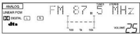
2. Press MULTI CURSOR △ / ▽ repeatedly until "- TUNING +" appears on the display.


3. Press MULTI CURSOR ◀/▶ until you find the frequency you want.
- Pressing ◀ decreases the frequency. - Pressing ▶ increases the frequency.

Notes:
- When you hold MULTI CURSOR ◀ / ▶ in step 3, the frequency keeps changing until a station is tuned in.
- When a station of sufficient signal strength is tuned in, the TUNED indicator lights up on the display. When an FM stereo program is received, the STEREO indicator also lights up.
Using Preset Tuning
Once a station is assigned to a channel number, the station can be quickly tuned. You can preset up to 30 FM and 15 AM stations.
To store the preset stations
Before you start, remember...
- There is a time limit in doing the following steps. If the setting is canceled before you finish, start from step 1 again.
On the front panel ONLY:
1. Tune in the station you want to preset (see "Tuning in Stations Manually").
If you want to store the FM reception mode for this station, select the FM reception mode you want. See "Selecting the FM Reception Mode" on page 17.

2. Press MEMORY.


"CH-" appears and the channel number position starts flashing on the display for about 5 seconds.
3. Press MULTI CURSOR ◀/▷ to select a channel number while the channel number position is flashing.

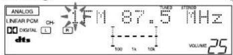
Note:
You can use the 10 keys on the remote control to select the preset number. When using the 10 keys, be sure that they are activated for the tuner, not for the CD and others. (See page 29.)
4. Press MEMORY again while the selected channel number is flashing on the display.

The selected channel number stops flashing.
The station is assigned to the selected channel number.
5. Repeat steps 1 to 4 until you store all the stations you want.
To erase a stored preset station
Storing a new station on a used number erases the previously stored one.
To tune in a preset station On the front panel:
1. Press FM/AM to select the band.
- The MULTI CURSOR ▲/▼/◀/▶ buttons can now be used for operating the tuner. • Each time you press the button, the band alternates between FM and AM.
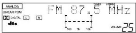

2. Press MULTI CURSOR ▲/▼ repeatedly until “- PRESET +” appears on the display.


3. Press MULTI CURSOR ◀/▶ to select a preset channel station.
- Pressing ◀ decreases the preset channel number.
- Pressing ▶ increases the preset channel number.
From the remote control:
1. Press FM/AM.
• Each time you press the button, the band alternates between FM and AM.


2. Press 10 keys to select a preset channel number.
- For channel number 5, press 5.
- For channel number 15, press +10 then 5.
- For channel number 20, press +10 then 10.
- For channel number 30, press +10, +10, then 10.

Note:
When you use the 10 keys on the remote control, be sure that they are activated for the tuner, not for the CD and others. (See page 29.)
Selecting the FM Reception Mode
When an FM stereo broadcast is hard to receive or noisy
You can change the FM reception mode while receiving an FM broadcast.
On the front panel ONLY:
- If necessary, press FM/AM so that the MULTI CURSOR △ / ▽ / ◁ / ▷ buttons can be now used for operating the tuner.
• Each time you press the button, the band alternates between FM and AM.

- Press MULTI CURSOR △ / ▽ repeatedly until “FM MODE” appears on the display.

- Press MULTI CURSOR ◀/▷ to switch the FM reception to "AUTO MUTING" or "MONO."


AUTO MUTING: When a program is broadcasted in stereo, you will hear stereo sound; when in monaural, you will hear monaural sounds. This mode is also useful to suppress static noise between stations. The AUTO MUTING indicator lights up on the display.
MONO: Reception will be improved although you will lose the stereo effect. In this mode, you will hear noise while tuning into the stations. The AUTO MUTING indicator goes off on the display.
The built-in Surround Processor provides three types of the DSP (Digital Signal Processor) mode — 3D-PHONIC mode, DAP (Digital Acoustic Processor) mode and Surround mode.
3D-PHONIC modes
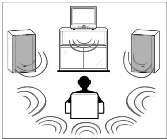
The 3D-PHONIC mode gives you such a nearly surround effect as it is reproduced through the Dolby Surround decoder, which is widely used to reproduce sounds with a feeling of movement like those experienced in movie theaters. The 3D-PHONIC mode is the result of research on sound localization technology carried out at JVC for many years. This mode can be used when the front speakers are connected to this receiver (without respect to the rear/center speaker connection).
- You can select either 3D ACTION or 3D THEATER to your preference when playing an analog or Linear PCM (digital) source.
3D ACTION: Best for action and war movies — where the action is fast and explosive.
3D THEATER: Reproduces the sound field of a large theater. This mode can be selected when only front speakers are connected to this receiver and "REAR SPK" and "CENTER SPK" is set to "NONE" (see page 12).
DAP modes
The sound heard in a concert hall or club consists of direct sound and indirect sound — early reflections and reflections from behind. Direct sounds reach the listener directly without any reflection. On the other hand, indirect sounds are delayed by the distances of the ceiling and walls. These direct sounds and indirect sounds are the most important elements of the acoustic surround effects. The DAP mode can create these important elements, and gives you a real “being there” feeling. This mode can be used when the front speakers are connected to this receiver (without respect to the rear/center speaker connection).
You can select one of the following to your preference.
LIVE CLUB: Gives the feeling of a live music club with a low ceiling.
DANCE CLUB: Gives a throbbing bass beat.
HALL: Gives clear vocal and the feeling of a concert hall.
PAVILION: Gives the spacious feeling of a pavilion with a high ceiling.

Notes:
- If "REAR SPK" and "CENTER SPK" are set to "NONE," — you can select only "HEAD PHONE" or "OFF" for the DSP mode. — you cannot select Surround mode.
- No sounds come out of the center speaker, even if it is connected.
Headphones mode
This mode can reproduce the LFE channel signals, mixing them to the front channel signals. So you will not miss the subwoofer sounds even if you listen to a source using the headphones.
Surround modes
With this receiver, you can use three types of the Surround mode. Following modes cannot be used when only the front speakers are connected to this receiver (without the rear speakers or center speaker).
Dolby Surround (Dolby Digital and Dolby Pro Logic) *
Used to watch the soundtracks of software encoded with Dolby Digital (bearing the mark ☐DOLBY) or with Dolby Surround (bearing the mark ☐DOLBY SURROUND).
Dolby Digital and Dolby Pro Logic can be selected automatically according to software played back and the speaker arrangement you have done.
- To enjoy the software encoded with Dolby Digital, you must connect the source component using the digital terminal on the rear of this receiver. (See page 7.)
DTS Digital Surround **
DTS Digital Surround is a discrete 5.1 channel digital audio format available on CD, LD, and DVD software.
To watch the soundtracks of video software bearing the mark, the receiver can provide you with DTS Digital Surround decoder. DTS Digital Surround is automatically selected according to software played back and the speaker arrangement you have done.
- To enjoy the software encoded with DTS Digital Surround, you must connect the source component using the digital terminal on the rear of this receiver. (See page 7.)
Note:
When playing a CD encoded with DTS Digital Surround, select "DTS" as the incoming digital signal type. (See page 14)
JVC Theater Surround
In order to reproduce a more realistic sound field in your listening room while playing soundtracks of software encoded with Dolby Surround (bearing the mark ☐☐[DOLBY SURROUND]), you can use JVC Theater Surround.

Notes:
- The DSP modes have no effect on monaural sources.
- The DSP modes will not be applied when recording a source.
- The PRO LOGIC indicator lights up when the Dolby Pro Logic decoder built in this receiver is activated.
* Manufactured under license from Dolby Laboratories. "Dolby," "Pro Logic," and the double-D symbol are trademarks of Dolby Laboratories. Confidential Unpublished Works. ©1992–1998 Dolby Laboratories, Inc. All rights reserved. ** Manufactured under license from Digital Theater Systems, Inc. US Pat. No. 5,451,942 and other world-wide patents issues and pending. "DTS" and "DTS Digital Surround" are trademarks of Digital Theater Systems, Inc. ©1996 Digital Theater Systems, Inc. All rights reserved.
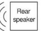
Available DSP Modes According to the Speaker Arrangement
Available DSP modes will vary depending on how many speakers are used with this receiver. Make sure that you have set the speaker information correctly (see page 12).
| Speaker arrangements | Available DSP modes | |||
 |   | Each time you press DSP MODE on the front panel or SURROUND MODE on the remote control, the DSP modes change as follows:3D THEATERLIVE CLUBDANCE CLUBHALLPAVILIONHEAD PHONE3D ACTIONDSP OFF (DSP mode is canceled)Notes:You can only select "HEAD PHONE" while playing a multi-sound source encoded with Dolby Digital or DTS Digital Surround.You cannot select the Surround mode with this speaker setting. | ||
 |  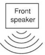 | Each time you press DSP MODE on the front panel or SURROUND MODE on the remote control, the DSP modes change as follows:By pressing DSP MODE:THEATERLIVE CLUBDANCE CLUBHALLPAVILIONHEAD PHONE3D ACTIONDSP OFF (DSP mode is canceled)To activate the Surround mode,press SURROUND button so that the lamp next to the button lights up. | By pressing SURROUND MODE:DOLBY/DTS SURROUND(DOLBY PRO LOGIC, DOLBY DIGITAL, or DTS SURROUND)THEATERLIVE CLUBDANCE CLUBHALLPAVILIONHEAD PHONE3D ACTIONDSP OFF (DSP mode is canceled)To activate the Surround mode,you can also use the SURROUND button. | |
 |   | |||
 |   | |||
 |   | |||
 |   | |||
Adjusting the 3D-PHONIC Modes
Once you have adjusted the 3D-PHONIC modes, the adjustment is memorized for each 3D-PHONIC mode.
Before you start, remember...
- Make sure that you have set the speaker information correctly (see page 12).
- There is a time limit in doing the following steps. If the setting is canceled before you finish, start from step 1 again.
On the front panel:
1. Press DSP MODE repeatedly until "3D ACTION" or "3D THEATER" appears on the display.

The 3D-PHONIC, DSP, and PRO LOGIC indicators also light up on the display.
2. Adjust the effect level.
1) Press ADJUST repeatedly until "DSP EFFECT" appears on the display.
- Once you have pressed ADJUST, MULTI CURSOR / can be also used for selecting "DSP EFFECT."
- The display changes to show the current setting.
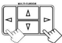
2) Press MULTI CURSOR / to select the effect level.
• As you press it, the effect level changes as follows:

![graph LR A["DSP EFFECT 1 DSP EFFECT 2 DSP EFFECT 3"] --> B["DSP EFFECT 4 DSP EFFECT 5"] B --> C["←"] C --> D["→"]](/content/2026/06/1313398/images/d5b5e97408991ae81f7e79fca830a953814231d3013e8f90245a03ab514c9590.jpg)
As the number increases, the selected 3D-PHONIC mode becomes stronger.
From the remote control:
1. Press SURROUND MODE repeatedly until "3D ACTION" or "3D THEATER" appears on the display.
The 3D-PHONIC, DSP, and PRO LOGIC indicators also light up on the display.
2. Press SOUND.
The 10 keys are activated for sound adjustments.
3. Press EFFECT to select an effect level you want.
• Each time you press the button, the effect level changes as follows:


As the number increases, the selected 3D-PHONIC mode becomes stronger.
Adjusting the DAP Modes and Headphones mode
Once you have adjusted the DAP modes, the adjustment is memorized for each DAP mode.
Before you start, remember...
- Make sure that you have set the speaker information correctly (see page 12).
- There is a time limit in doing the following steps. If the setting is canceled before you finish, start from step 1 again.
- You cannot adjust the rear speaker output level when you have set "REAR SPK" to "NONE." See page 12.
- You cannot make any adjustment for the headphones mode.
On the front panel:
1. Press DSP MODE repeatedly until the DAP mode — LIVE CLUB, DANCE CLUB, HALL, PAVILION, or HEAD PHONE — appears on the display.

The DSP indicator also lights up on the display. (When the HEAD PHONE is selected, HEAD PHONE indicator lights up, instead of the DSP indicator.)
- When you have set “REAR SPK” to “NONE,” the 3D-PHONIC indicator also lights up. (Except for “HEAD PHONE.”)
2. Adjust the speaker output levels.
1) Press ADJUST repeatedly until one of the following indications appears on the display.
"REAR L LEVEL":
To adjust the left rear speaker level.
"REAR R LEVEL":
To adjust the right rear speaker level.
- Once you have pressed ADJUST, MULTI CURSOR / can be also used for selecting the speaker.
2) Press MULTI CURSOR / to adjust the selected speaker output level (from -10 dB to +10 dB). 3) Repeat 1) and 2) to adjust the other speaker output level.
3. Adjust the effect level.
1) Press ADJUST repeatedly until "DSP EFFECT" appears on the display.
- Once you have pressed ADJUST, MULTI CURSOR / can be also used for selecting "DSP EFFECT."
- The display changes to show the current setting.
2) Press MULTI CURSOR / to select the effect level.
- As you press it, the effect level changes as follows:


![graph LR A["DSP EFFECT 1"] --> B["DSP EFFECT 2"] B --> C["DSP EFFECT 3"] C --> D["DSP EFFECT 4"] D --> E["DSP EFFECT 5"] E --> F["DSP EFFECT 6"]](/content/2026/06/1313398/images/56d42e2602a62a3512edd3ea2134391b24d87fce8b77992341a4e179ddc4bab8.jpg)
As the number increases, the selected DAP mode becomes stronger.
From the remote control:
- Press SURROUND MODE repeatedly until the DAP mode — LIVE CLUB, DANCE CLUB, HALL, PAVILION, or HEAD PHONE — appears on the display.
The DSP indicator also lights up on the display. (When HEAD PHONE is selected, the HEAD PHONE indicator lights up instead of the DSP indicator.)
When you have set "REAR SPK" to "NONE," the 3D-PHONIC indicator also lights up. (Except for "HEAD PHONE.")

- Press SOUND.
The 10 keys are activated for sound adjustments.

- Adjust the rear speaker output levels.
• To adjust the left rear speaker level, press REAR•L -/+ (from -10 dB to +10 dB). • To adjust the right rear speaker level, press REAR•R -/+ (from -10 dB to +10 dB).

- Press EFFECT to select the desired effect level.
• Each time you press the button, the effect level changes as follows:
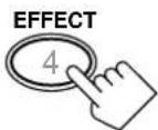

As the number increases, the selected DAP mode becomes stronger.
Adjusting the Surround Modes
Once you have adjusted the Surround modes, the adjustment is memorized for each Surround mode.
Dolby and DTS Surround adjustments
Before you start, remember...
- Make sure that you have set the speaker information correctly (see page 12).
- There is a time limit for completing the following steps. If the setting is canceled before you finish, start again from step 1.
- You cannot adjust the rear speaker output levels when "REAR SPK" is set to "NONE." See page 12.
- You cannot adjust the center speaker output level when "CENTER SPK" is set to "NONE." See page 12.
From the remote control:
- Press SURROUND to activate an appropriate Surround mode — PRO LOGIC, DOLBY DIGITAL, or DTS SURROUND.
• Each time you press the button, the Surround mode turns on and off alternately. - When "PRO LOGIC" is selected, the PRO LOGIC indicator lights up on the display.

Note:
You can also press SURROUND MODE to activate an appropriate Surround mode — PRO LOGIC, DOLBY DIGITAL, or DTS.
- Press SOUND.
The 10 keys are activated for sound adjustments.

- Press TEST to check the speaker output balance.
"TEST TONE L" starts flashing on the display, and a test tone comes out of the speakers in the following order:
TEST TONE L → TEST TONE C → TEST TONE R (Left front speaker) (Center speaker) (Right front speaker)
TEST TONE LS ← TEST TONE RS (Left rear speaker) (Right rear speaker)
Notes:
- You can adjust the speaker output levels without outputting the test tone.
- No test tone comes out of the center speaker when "CENTER SPK" is set to "NONE" (see page 12).
- No test tone comes out of the rear speakers when "REAR SPK" is set to "NONE" (see page 12).
4. Adjust the speaker output levels.
• To adjust the center speaker level, press CENTER -/+ (from -10 dB to +10 dB). • To adjust the left rear speaker level, press REAR•L -/+ (from -10 dB to +10 dB). • To adjust the right rear speaker level, press REAR•R -/+ (from -10 dB to +10 dB).
![graph TD A["CENTER + 5"] --> B["REAR·L + 8"] B --> C["REAR·R + 10"] C --> D["+10 CENTER"]](/content/2026/06/1313398/images/7e92139d745b95cd0f16b0ac9389362a83b5dba7f57a9716c1166608214ad2e2.jpg)
5. Press TEST again to stop the test tone.

On the front panel:
You can also use the buttons on the front panel to adjust the Surround modes. However, no test tone is available when using the buttons on the front panel. So, make adjustments while listening to the sound of the source played back.
1. Press SURROUND to activate an appropriate Surround mode — PRO LOGIC, DOLBY DIGITAL or DTS SURROUND.

• Each time you press the button, the Surround mode turns on and off alternately. - When "PRO LOGIC" is selected, the □□ PRO LOGIC indicator lights up on the display.
2. Adjust the speaker output levels.
1) Press ADJUST repeatedly until one of the following indications appears on the display.
"CENTER LEVEL":
To adjust the center speaker level.
"REAR L LEVEL":
To adjust the left rear speaker level.
"REAR R LEVEL":
To adjust the right rear speaker level.
- Once you have pressed ADJUST, MULTI CURSOR / can be also used for selecting the speaker.
2) Press MULTI CURSOR </> to adjust the selected speaker output level (from -10 dB to +10 dB). 3) Repeat 1) and 2) to adjust the other speaker output levels.


JVC Theater Surround adjustments
Before you start, remember...
- Make sure that you have set the speaker information correctly (see page 12).
- There is a time limit in doing the following steps. If the setting is canceled before you finish, start from step 1 again.
- You cannot adjust the rear speaker output levels when you have set "REAR SPK" to "NONE." See page 12.
- You cannot adjust the center speaker output level and center tone when you have set "CENTER SPK" to "NONE." See page 12.
From the remote control:
1. Press SURROUND MODE repeatedly until "THEATER" appears on the display.
- The PRO LOGIC and DSP indicators also light up on the display.

2. Press SOUND.
The 10 keys are activated for sound adjustments.
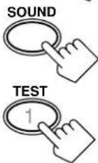
3. Press TEST to check the speaker output balance.
"TEST TONE L" starts flashing on the display, and a test tone comes out of the speakers in the following order:
![graph LR A["TEST TONE L\n(Left front speaker)"] --> B["TEST TONE C\n(Center speaker)"] B --> C["TEST TONE R\n(Right front speaker)"] D["TEST TONE LS\n(Left rear speaker)"] <--_E["TEST TONE RS\n(Right rear speaker)"]](/content/2026/06/1313398/images/be7d67ae110a4d27931031edcd34d20048d5e3f234bb0ccd54848ed1c373741c.jpg)
Notes:
- You can adjust the speaker output levels without outputting the test tone.
- No test tone comes out of the center speaker when "CENTER SPK" is set to "NONE" (see page 12).
- No test tone comes out of the rear speakers when "REAR SPK" is set to "NONE" (see page 12).
4. Adjust the speaker output levels.
• To adjust the center speaker level, press CENTER -/+ (from -10 dB to +10 dB). • To adjust the left rear speaker level, press REAR•L -/+ (from -10 dB to +10 dB). • To adjust the right rear speaker level, press REAR•R -/+ (from -10 dB to +10 dB).
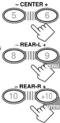
5. Press TEST again to stop the test tone.
6. Press EFFECT to select an effect level you want.
• Each time you press the button, the effect level changes as follows:


DSP EFFECT 1 DSP EFFECT 2 DSP EFFECT 3
← DSP EFFECT 4DSP EFFECT 5
As the number increases, JVC Theater Surround becomes stronger.
On the front panel:
You can also use the buttons on the front panel to adjust the Surround modes. However, no test tone is available when using the buttons on the front panel. So, make adjustments while listening to the sound of the source played back.
1. Press DSP MODE repeatedly until "THEATER" appears on the display.
• The PRO LOGIC and DSP indicators also light up on the display.

2. Adjust the speaker output levels.
1) Press ADJUST repeatedly until one of the following indications appears on the display.
"CENTER LEVEL": To adjust the center speaker level. "REAR L LEVEL": To adjust the left rear speaker level. "REAR R LEVEL":
To adjust the right rear speaker level.
- Once you have pressed ADJUST, MULTI CURSOR ▲/▼ can be also used for selecting the speaker.
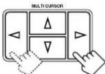
2) Press MULTI CURSOR ◀/▶ to adjust the selected speaker output level (from -10 dB to +10 dB).
3) Repeat 1) and 2) to adjust the other speaker output levels.


4. Adjust the effect level.
1) Press ADJUST repeatedly until "DSP EFFECT" appears on the display.
- Once you have pressed ADJUST, MULTI CURSOR ▲/▼ also can be used for selecting "DSP EFFECT." - The display changes to show the current setting.
2) Press MULTI CURSOR ◀/▶ to select the effect level.
- As you press it, the effect level changes as follows:

DSP EFFECT 1 DSP EFFECT 2 DSP EFFECT 3
←→DSP EFFECT 4DSP EFFE
As the number increases, JVC Theater Surround becomes stronger.
Activating the DSP Modes
You can use only one DSP mode at a time. When a DSP mode is activated, another DSP mode is canceled if in use.
For Dolby Pro Logic, Dolby Digital, and DTS Digital Surround
On the front panel:
1. Press SURROUND so that the lamp next to the button lights up.
• Each time you press the button, the Dolby/DTS Surround mode turns on and off alternately.

2. Select and play a sound source.
- To enjoy Dolby Pro Logic, play back a software encoded with Dolby Surround and labeled with ☐DOLBY SURROUND mark.
- To enjoy Dolby Digital, play back a software encoded with Dolby Digital and labeled with □□□□□□□□□□□□□□□□□□□□□□□□□□□□□□□□□□□□□□□□□□□□□□□□□□□□□□□□□□□□□□□□□□□□□□□□□□□□□□□□□□□□□□□□□□□□□□□□□□□□□ □DOLBY mark.
- To enjoy DTS Digital surround, play back a software encoded with DTS Digital Surround and labeled with mark.
To cancel the Dolby/ DTS Surround mode
Press SURROUND again so that the lamp goes off. ("SURROUND OFF" appears on the display.)

From the remote control:
1. Press SURROUND so that the lamp on the front panel lights up.
• Each time you press the button, the Dolby/DTS Surround mode turns on and off alternately. - You can also turn on Dolby/DTS Surround mode by pressing SURROUND MODE. (See page 22 for more details.)

2. Select and play a sound source.
- To enjoy Dolby Pro Logic, play back a software encoded with Dolby Surround and labeled with the DOLBY SURROUND mark.
- To enjoy Dolby Digital, play back a software encoded with Dolby Digital and labeled with the DOLBY mark.
- To enjoy DTS Digital Surround, play back a software encoded with DTS Digital Surround and labeled with the DTS mark.
To cancel the Dolby/DTS Surround mode
Press SURROUND again. ("SURROUND OFF" appears on the display.)

For the other DSP modes
On the front panel:
1. Press DSP MODE repeatedly until the mode you want appears on the display.
• Each time you press the button, the DSP modes change. (See page 20 for more details.)
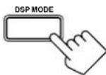
2. Select and play a sound source.
• To enjoy 3D-PHONIC and JVC Theater Surround, play back a software encoded with Dolby Surround and labeled with the DOLBY SURROUND mark.
To cancel the DSP mode
Press DSP MODE repeatedly until "DSP OFF" appears on the display.

From the remote control:
1. Press SURROUND MODE repeatedly until the DSP mode you want appears on the display.
• Each time you press the button, the DSP modes change. (See page 20 for more details.)

2. Select and play a sound source.
- To enjoy 3D-PHONIC and JVC Theater Surround, play back a software encoded with Dolby Surround and labeled with the DOLBY SURROUND mark.
To cancel the DSP mode
Press SURROUND MODE repeatedly until "DSP OFF" appears on the display.
COMPU LINK Remote Control System
The COMPU LINK remote control system allows you to operate JVC audio components through the remote sensor on the receiver.
To use this remote control system, you need to connect JVC audio components through the COMPU LINK-3 (SYNCHRO) jacks (see below) in addition to the connections using cables with RCA pin plugs (see page 5).
- Make sure that the AC power cords of these components are unplugged before connection. Plug the AC power cords only after all connections are complete.
![graph TD A["CD player"] --> B["Cassette deck or MD recorder"] B --> C["COMPU LINK-3 (SYNCHRO)"] C --> D["Turntable"]](/content/2026/06/1313398/images/fbfbbbe4492145b51d1f67b183fd6a0927e2092a3530266c938e5ab4e7aba08d.jpg)
Notes:
- If your audio component has two COMPU LINK-3 (SYNCHRO) jacks, you can use either one. If it has only one COMPU LINK-3 (SYNCHRO) jack, connect it so that it is the last item in the series of components. (For example, the turntable or CD player in the diagram above.)
- To operate the cassette deck or MD recorder using the COMPU LINK remote control system, set the source name correctly. (See page 11.)
- Refer also to the manuals supplied with your audio components.
This remote control system allows you to use four functions listed below.
Remote Control through the Remote Sensor on the Receiver
You can control the connected audio components through the remote sensor on the receiver using this remote control. Aim the remote control directly at the remote sensor on the receiver. For details, see pages 29 and 30.
Automatic Source Selection
When you press the play (▶) button on a connected component or on its own remote control, the receiver automatically turns on and changes the source to the component. On the other hand, if you select a new source on the receiver or on the remote control, the selected component begins playing immediately.
In both cases, the previously selected source continues playing without sound for a few seconds.
Automatic Power On/ Off (Standby): only possible with the COMPU LINK-3 connection
Both the CD player and cassette deck (or MD recorder) turn on and off (standby) along with the receiver.
When you turn on the receiver, the CD player or cassette deck (or MD recorder) will turn on automatically, depending on which component has been previously selected.
When you turn off the receiver, both the CD player and cassette deck (or MD recorder) will turn off (standby).
Synchronized Recording
Synchronized recording means the cassette deck (or MD recorder) starts recording as soon as a CD or a record begins playing.
To use synchronized recording, follow these steps:
- Put a tape in the cassette deck (or an MD in the MD recorder), and a disc in the CD player (or a record on the turntable).
- Press the record (●) button and the pause (II) button on the cassette deck (or MD recorder) at the same time.
This puts the cassette deck (or MD recorder) into recording pause.
If you do not press the record (●) button and pause (■) button at the same time, the synchronized recording feature will not operate.
- Press the play (▶) button on the CD player or on the turntable.
The source changes on the receiver, and as soon as play starts, the cassette deck (or MD recorder) starts recording. When the play ends, the cassette deck (or MD recorder) enters recording pause, and stops about 4 seconds later.
Notes:
- During synchronized recording, the selected source cannot be changed.
- If the power of any component is shut off during synchronized recording, the COMPU LINK remote control system may not operate properly. In this case, you must start again from the beginning.
AV COMPU LINK Remote Control System
The AV COMPU LINK remote control system allows you to operate JVC video components (TV, VCR, and DVD player) through the receiver.
To use this remote control system, you need to connect the video components you want to operate, follow the diagrams below and the procedure on the next page.
CONNECTIONS 1:![graph TD A["VCR"] --> B["COMPULINK"] C["DVD player"] --> D["COMPULINK"] D --> E["AV COMPU LINK"] E --> F["TV"] G["TV"] --> H["RECEIVER/AMP"] H --> I["EX"] J["TV"] --> K["FEDVER/AMP"] K --> L["EX"] M["TV"] --> N["COMPUT LINK"] N --> O["EX"] P["TV"] --> Q["COMPUT LINK"] Q --> R["EX"] S["TV"] --> T["CO…](/content/2026/06/1313398/images/4408d2cc0f34cb07b177007352c5bd71115fe8a36055244ec1ce3d2028334492.jpg)
CAUTION
The AV COMPU LINK remote control system cannot control the DBS tuner connected to the TV SOUND/DBS jacks.
Notes:
- When connecting only the VCR or DVD player to this receiver, connect it directly to the receiver using cables with monaural mini-plugs. • Refer also to the manuals supplied with your video components.
CONNECTIONS 2:
CASE1: If the DVD player is equipped with the S-video terminals
CASE2: If the DVD player is not equipped with the S-video terminals

- If you have already plugged your VCR, DVD player, TV, and this receiver into the AC outlets, unplug their AC power cords first.
- Connect your VCR, DVD player, TV, and this receiver, using the cables with the monaural mini-plugs (not supplied).
- See "CONNECTIONS 1" on the previous page.
- Connect the audio input/output jacks on VCR, DVD player, TV, and this receiver using the cables with RCA pin plug
• See pages 5 and 6.
- Connect the video input/output jacks on VCR, DVD player, TV, and this receiver, using the cables with RCA pin plug or with S-video plug.
- See “CONNECTIONS 2” on the previous page.
- Plug the AC power cords of the components into the AC outlets.
- When turning on the TV for the first time after the AV COMPU LINK connection, turn the TV volume to the minimum using the TV volume control on the TV.
- Turn on the other connected components first, then turn on this receiver.
- When turning on the VCR, use the remote control supplied with this receiver (press VCR POWER).
The AV COMPU LINK remote control system allows you to use the five basic functions listed below.
Remote Control of the TV, DVD player, and VCR Using This Remote Control
See page 30 for details.
For the DVD player and the VCR:
- Aim the remote control directly at the remote sensor on each component.
For the TV having AV COMPU LINK terminal "RECEIVER/AMP":
- Aim the remote control directly at the remote sensor on the receiver.
For the TV having AV COMPU LINK terminal "AV COMPU LINK EX":
- Aim the remote control directly at the remote sensor on the TV.
One-Touch Video Play
Simply by inserting a video cassette without its safety tab into the VCR, you can enjoy the video playback without setting other switches manually. The receiver automatically turns on and changes the source to "VCR."
The TV automatically turns on and changes the input mode to the position so that you can view the playback picture.
When you insert a video cassette with its safety tab, press the play
(▶) button on the VCR or on the remote control. So, you can get the same result.
One-Touch DVD Play
Simply by starting playback on the DVD player, you can enjoy the DVD playback without setting other switches manually.
- When the DVD player is connected through the analog input jacks on this receiver (and analog input is selected), the receiver automatically turns on and changes the source to "DVD."
- When the DVD player is connected through the digital input terminal on this receiver (and digital input is selected), the receiver automatically turns on and changes the source to "DVD DIGITAL."
The TV automatically turns on and changes the input mode to the position so that you can view the playback picture.
Automatic Selection of TV's Input Mode
- When you select "TV SOUND" as the source to play on the receiver, the TV automatically changes the input mode to the TV tuner so that you can watch TV.
- When you select "DVD" (or "DVD DIGITAL"), "VCR," or "DBS" (or "DBS DIGITAL") as the source to play on the receiver, the TV automatically changes the input mode to the appropriate position (either Video Input 1 or Video Input 2) so that you can view the playback picture.
Automatic Power On/Off
The TV, VCR, and DVD player turn on and off along with the receiver.
When you turn on the receiver:
- If the previously selected source is “VCR,” the TV and VCR will turn on automatically.
- If the previously selected source is “TV SOUND” or “DBS” (or “DBS DIGITAL”), only the TV will turn on automatically.
- If the previously selected source is “DVD” (or “DVD DIGITAL”), the TV and DVD player will turn on automatically.
When you turn off the receiver, the TV, VCR, and DVD player will turn off.
Note:
If you turn off the receiver while recording on the VCR, the VCR will not turn off, but will continue recording.
Operating JVC's Audio/Video Components
You can operate JVC's audio and video components with this receiver's remote control, since control signals for JVC components are preset in the remote control.
IMPORTANT:
To operate JVC's audio components using this remote control:
- You need to connect JVC audio components through the COMPU LINK-3 (SYNCHRO) jacks (see page 26) in addition to the connections using cables with RCA pin plugs (see page 5).
- Aim the remote control directly at the remote sensor on the receiver.
- If you use the buttons on the front panel to choose a source, the remote control will not operate that source. To operate a source with the remote control, the source must be selected using source selecting buttons on the remote control.
- To operate the cassette deck or MD recorder using the COMPU LINK remote control system, set the source name correctly. (See page 11.) • Refer also to the manuals supplied with your components.

Tuner
After pressing FM/AM, you can perform the following operations:
FM/AM:
Alternates between FM and AM.
1 - 10, +10:
Selects a preset channel number directly.
For channel number 5, press 5.
For channel number 15, press +10, then 5.
For channel number 20, press +10, then 10.
Sound control section (Amplifier)
You can always perform the following operations:
SURROUND: Turns on or off the Surround modes —
Dolby Pro Logic, Dolby Digital, and DTS
Digital Surround.
SURROUND MODE: Selects the DSP modes.
After pressing SOUND, you can perform the following operations:
SUBWOOFER - / +: Adjusts the subwoofer output level.
CENTER - / +: Adjusts the center speaker output level.
REAR•L - / +: Adjusts the left rear speaker output level.
REAR·R - / +: Adjusts the right rear speaker output level.
EFFECT: Selects the effect level.
TEST: Turns on or off the test tone output.
Note:
After adjusting sounds, press the corresponding source selecting button or CD-DISC to operate your target source by using the 10 keys; otherwise, the 10 keys cannot be used for operating your target source.
Turntable
After pressing PHONO, you can perform the following operations on a turntable:
▶: Starts playing.
■: Stops operations.
CD player
After pressing CD, you can perform the following operations on the CD player:
▶: Starts playing.
Returns to the beginning of the current (or previous) track.
▶▶: Skips to the beginning of the next track.
■: Stops playing.
■: Pauses playing. To release it, press ▶.
1 - 10, +10: Selects a track number directly.
For track number 5, press 5.
For track number 15, press +10, then 5.
For track number 20, press +10, then 10.
For track number 30, press +10, +10, then 10.
CD player-changer
After pressing CD-DISC, you can perform the following operations on a CD player-changer:
▶: Starts playing. ◀◀: Returns to the beginning of the current (or previous) track. ▶▶: Skips to the beginning of the next track. ■: Stops playing. ■: Pauses playing. To release it, press ▶.
1 - 6, 7/P: Selects the number of a disc installed in a CD player-changer.
If your CD changer is of 200-disc loading capability (except for XL-MC100 and XL-MC301),
you can do the following operations using the number buttons after pressing CD.
- 10 button can function as 0.
- Select a disc number.
- Then select a track number (always enter two digits).
- Start playback.
Ex.
Selecting disc number 3, track number 2, and start playback.
Press 3, then, 10, 2, then ▶.
Selecting disc number 10, track number 5, and start playback.
Press 1, 10, then, 10, 5, then ▶.
Selecting disc number 105, track number 12, and start playback.
Press 1, 10, 5, then 1, 2 then ▶.
Cassette deck
After pressing TAPE/MD, you can perform the following operations on a cassette deck:
▶: Starts playing. ◀: Fast winds the tape from right to left. ▶▶: Fast winds the tape from left to right. ■: Stops operations. ■: Pauses playing. To release it, press ▶.
MD recorder
After pressing TAPE/MD, you can perform the following operations on the MD recorder:
▶: Starts playing. ◀◀: Returns to the beginning of the current (or previous) track. ▶▶: Skips to the beginning of the next track. ■: Stops playing. II: Pauses playing. To release it, press ▶.
Note:
Before starting the above operations, make sure that you have changed the source name correctly. See page 11.
IMPORTANT:
To operate JVC's video components using this remote control:
- You need to connect JVC video components through the AV COMPU LINK terminals (see page 27) in addition to the connections using cables with RCA pin plugs (see page 6).
- Some JVC VCRs can accept two types of the control signals — remote code “A” and “B.” Before using this remote control, make sure that the remote control code of the VCR connected to the VCR jacks is set to code “A.”
- When using the remote control:
- For the DVD player and VCR operations, aim the remote control directly at the remote sensor on each component, not on the receiver.
- For the TV operations:
If the TV has the AV COMPU LINK terminal "RECEIVER/AMP," aim the remote control directly at the remote sensor on the receiver. ■ If the TV has the AV COMPU LINK terminal "AV COMPU LINK EX," aim the remote control directly at the remote sensor on the TV.
VCR
You can always perform the following operations:
VCR POWER: Turns on or off the VCR.
After pressing VCR, you can perform the following operations on the VCR:
1 - 9, 0: Selects the TV channels on VCR. ▶: Starts playing. ◀◀: Rewinds a tape. ▶▶: Fast winds a tape. ■: Stops operations. II: Pauses playing. To release it, press ▶. VCR CH +/-: Changes the TV channels on the VCR.
DVD player
After pressing DVD, you can perform the following operations on a DVD player:
▶: Starts playing. Returns to the beginning of the current (or previous) track. ▶▶: Skips to the beginning of the next track. ■: Stops playing. ■: Stops playing temporarily. To release it, press ▶.
After pressing DVD, these buttons can be used for the DVD menu operations.

Note:
For detailed menu operations, refer to the instructions supplied with the discs or the DVD player.

TV
You can always perform the following operations:
TV POWER: Turns on or off the TV. TV/VIDEO: Sets the input mode (either TV or VIDEO). TV VOL +/-: Adjusts the volume. TV CH +/-: Changes the channels. 1 - 9, 0, +10: Selects the channels.
Troubleshooting
Use this chart to help you solve daily operational problems. If there is any problem you cannot solve, contact your JVC service center.
| PROBLEM | POSSIBLE CAUSE | SOLUTION |
| The display does not light up. | The power cord is not plugged in. | Plug the power cord into an AC outlet. |
| No sound from speakers. | Speaker signal cables are not connected. | Check speaker wiring and reconnect if necessary. |
| The SPEAKERS 1 and 2 buttons are not set correctly. | Press SPEAKERS 1 and 2 correctly. | |
| An incorrect source is selected. | Select the correct source. | |
| Muting is activated. | Press MUTING to cancel the mute. | |
| Sound from one speaker only. | Speaker signal cables are not connected properly. | Check speaker wiring and reconnect if necessary. |
| The balance is set to one extreme. | Adjust the balance properly (see page 11). | |
| Continuous hiss or buzzing during FM reception. | Incoming signal is too weak. | Connect an outdoor FM antenna or contact your dealer. |
| The station is too far away. | Select a new station. | |
| An incorrect antenna is used. | Check with your dealer to be sure you have the correct antenna. | |
| Antennas are not connected properly. | Check connections. | |
| Occasional cracking noise during FM reception. | Ignition noise from automobiles. | Move the antenna farther from automobile traffic. |
| Howling during record playing. | Your turntable is too close to speakers. | Move speakers away from the turntable. |
| “OVERLOAD” starts flashing on the display. | Speakers are overloaded because of high volume. | 1. Press POWER on the front panel to turn off the receiver.2. Stop the playback source.3. Turn on the receiver again, and adjust the volume. |
| Speakers are overloaded because of short circuit of speaker terminals. | Press POWER on the front panel to turn off the receiver, check the speaker wiring, then press it again to turn on the receiver again. If “OVERLOAD” does not disappear though speaker wiring is not short-circuited, consult your dealer. | |
| Remote control does not work. | There is an obstruction in front of the remote sensor on the receiver. | Remove the obstruction. |
| Batteries are weak. | Replace batteries. |
Amplifier
Output Power
At Stereo operation:
Front channels: 100 W per channel, min. RMS, driven into 8 Ω 40 Hz to 20 kHz with no more than 0.8% total harmonic distortion.
At Surround operation:
Front channels: 100 W per channel, min. RMS, driven into 8 Ω at 1 kHz with no more than 0.8% total harmonic distortion.
Center channel: 100 W, min. RMS, driven into 8 Ω at 1 kHz, with no more than 0.8% total harmonic distortion.
Rear channels: 100 W per channel, min. RMS, driven into 8 Ω at 1 kHz, with no more than 0.8% total harmonic distortion.
Audio
Audio Input Sensitivity/Impedance (1 kHz): PHONO (MM): 2.7 mV/47 k Ω
CD, TAPE/MD, TV SOUND/DBS, VCR, DVD:
220 mV/47 k Ω
Audio Input (DIGITAL IN)* : Coaxial: DIGITAL 1 (DVD): 0.5 V (p-p)/75 Ω
Optical: DIGITAL 2 (CD): -21 dBm to -15 dBm (660 nm ±30 nm)
* Corresponding to Linear PCM, Dolby Digital, and DTS Digital Surround (with sampling frequency — 32 kHz, 44.1 kHz, 48 kHz).
Audio Output Level: TAPE/MD, VCR: 220 mV
Signal-to-Noise Ratio ('66 IHF/'78 IHF): PHONO: 70 dB/78 dB (at REC OUT)
CD, TAPE/MD, TV SOUND/DBS, VCR, DVD:
87 dB/80 dB
Frequency Response (8 ohms): PHONO: 20 Hz to 20 kHz (±1 dB)
CD, TAPE/MD, TV SOUND/DBS, VCR, DVD:
20 Hz to 20 kHz (±1 dB)
RIAA Phono Equalization: ±1 dB (20 Hz to 20 kHz)
Bass Boost: +3 dB ±1
dB at 100 Hz
Tone Control: Bass (100 Hz): ±10 dB ±2 dB
Treble (10 kHz): ±10 dB ±2 dB
Video
Video Input Sensitivity/Impedance:
Composite video: DBS, VCR, DVD: 1 V (p-p)/75 Ω
S-video: DVD: (Y: luminance): 1 V (p-p)/75 Ω
(C: chrominance, burst): 0.286 V (p-p)/75 Ω
Video Output Level:
Composite video: VCR, MONITOR OUT: 1 V (p-p)/75 Ω
S-video: MONITOR OUT: (Y: luminance): 1 V (p-p)/75 Ω
(C: chrominance, burst): 0.286 V (p-p)/75 Ω
Synchronization: Negative
Signal-to-Noise Ratio: 45 dB
FM tuner (IHF)
Tuning Range: 87.5 MHz to 108.0 MHz
Usable Sensitivity: Monaural: 12.8 dBf (1.2 μV/75 Ω)
50 dB Quieting Sensitivity: Monaural: 21.3 dBf (3.2 μV/75 Ω)
Stereo: 41.3 dBf (31.5 μV/75 Ω)
Signal-to-Noise Ratio (IHF-A weighted): Monaural: 78 dB at 85 dBf
Stereo: 73 dB at 85 dBf
Total Harmonic Distortion: Monaural: 0.4% at 1 kHz
Stereo: 0.6% at 1 kHz
Stereo Separation at REC OUT: 35 dB at 1 kHz
Alternate Channel Selectivity: 45 dB: (±400 kHz)
Frequency Response: 30 Hz to 15 kHz: (+0.5 dB, -3 dB)
AM tuner
Tuning Range: 530 kHz to 1,710 kHz
Usable Sensitivity: Loop antenna 400 μV/m
Signal-to-Noise Ratio: 50 dB (100 mV/m)
General
Power Requirements: AC 120V, 60Hz
Power Consumption: 290 W/390 VA (at operation)
2 W (in standby mode)
Dimensions (W x H x D): 435 mm x 146 mm x 403.5 mm
(17 3/16 in. x 5 3/4 in. x 15 15/16 in.)
Mass: 10.2 kg (22.5 lbs)
Designs & specifications are subject to change without notice.
HOW TO LOCATE YOUR JVC SERVICE CENTER
TOLL FREE : 1-800-537-5722
http://www.jvcservice.com
Dear customer:
In order to receive the most satisfaction from your purchase, read the instruction booklet before operating the unit. In the event that repair is necessary, or for the address nearest your location, please refer to the factory service center list below or within the Continental United States, Call 1-800-537-5722 for your authorized servicer. Remember to retain your Bill of Sale for Warranty Service.
—JVC
JVC SERVICE & ENGINEERING
COMPANY OF AMERICA
DIVISION OF JVC AMERICAS CORP.
FACTORY SERVICE CENTER LOCATIONS
10 New Maple Avenue
Pine Brook, NJ 07058-9641
(973) 396-1000
5665 Corporate Avenue
Cypress, CA 90630-0024
(714) 229-8011
13 Cummings Park
Woburn, MA 01801
(781) 376-9100
1500 Lakes Parkway
Lawrenceville, GA 30243-5857
(770) 339-2582
2969 Mapunapuna Place
Honolulu, HI 96819-2040
(808) 833-5828
8192 State Road 84
Davie, FL 33324
(954) 472-1960
705 Enterprise Street
Aurora, IL 60504-8149
(630) 851-7855
10700 Hammerly, Suite 110
Houston, TX 77043
(713) 935-9331
890 Dubuque Avenue
South San Francisco, CA 94080-1804
(650) 871-2666
Sophisticated electronic products may require occasional service. Just as quality is a keyword in the engineering and production of the wide array of JVC products, service is the key to maintaining the high level of performance for which JVC is world famous. The JVC service and engineering organization stands behind our products.
NATIONAL HEADQUARTERS
JVC SERVICE & ENGINEERING COMPANY OF AMERICA
DIVISION OF JVC AMERICAS CORP.
1700 Valley Road
Wayne, NJ 07470
If you ship the product...
Pack your JVC unit in the original carton or one of equivalent size and strength. Enclose, with the unit, a letter stating the problem or symptom that exists and also a copy of the receipt or bill of sale you received when you purchased your JVC unit. Print your home return address on the outside and the inside of the carton. Send to the appropriate JVC Factory Service Center as listed above.
Don't service it yourself.
CAUTION
To prevent electrical shock, do not open the cabinet. No user serviceable parts inside.
Refer servicing to qualified service personnel.
ACCESSORIES
To purchase accessories for your JVC product, you may contact your local JVC Dealer. Or from the 48 Continental United States call toll free: 800-882-2345
JVC
LIMITED WARRANTY AUDIO-2
JVC COMPANY OF AMERICA warrants this product and all parts thereof, except as set forth below ONLY TO THE ORIGINAL PURCHASER AT RETAIL to be FREE FROM DEFECTIVE MATERIAL AND WORKMANSHIP from the date of original retail purchase for the period as shown below. ("The Warranty Period.")
| PARTS LABOR2YR 2YR |
THIS LIMITED WARRANTY IS VALID ONLY IN THE FIFTY(50) UNITED STATES, THE DISTRICT OF COLUMBIA AND IN COMMONWEALTH OF PUERTO RICO.
WHAT WE WILL DO:
If this product is found to be defective, JVC will repair or replace defective parts at no charge to the original owner. Such repair and replacement services shall be rendered by JVC during normal business hours at JVC authorized service centers. Parts used for replacement are warranted only for the remainder of the Warranty Period. All products and parts thereof may be brought to a JVC authorized service center on a carry-in basis except for Television sets having a screen size 25 inches and above which are covered on an in-home basis.
WHAT YOU MUST DO FOR WARRANTY SERVICE:
Return your product to a JVC authorized service center with a copy of your bill of sale. For your nearest JVC authorized service center, please call toll free: (800)537-5722. If service is not available locally, box the product carefully, preferably in the original carton, and ship, insured, with a copy of your bill of sale plus a letter of explanation of the problem to the nearest JVC Factory Service Center, the name and location of which will be given to you by the toll-free number. If you have any questions concerning your JVC Product, please contact our Customer Relations Department.
WHAT IS NOT COVERED:
This limited warranty provided by JVC does not cover:
- Products which have been subject to abuse, accident, alteration, modification, tampering, negligence, misuse, faulty installation, lack of reasonable care, or if repaired or serviced by anyone other than a service facility authorized by JVC to render such service, or if affixed to any attachment not provided with the products, or if the model number or serial number has been altered, tampered with, defaced or removed;
- Initial installation and installation and removal for repair;
- Operational adjustments covered in the Owner's Manual, normal maintenance, video and audio head cleaning;
- Damage that occurs in shipment, due to act of God, and cosmetic damage;
- Signal reception problems and failures due to line power surge;
- Video Pick-up Tubes/CCD Image Sensor, Cartridge, Stylus(Needle) are covered for 90 days from the date of purchase;
- Accessories;
- Batteries (except the Rechargeable Batteries are covered for 90 days from the date of purchase);
There are no express warranties except as listed above.
THE DURATION OF ANY IMPLIED WARRANTIES, INCLUDING THE IMPLIED WARRANTY OF MERCHANTABILITY, IS LIMITED TO THE DURATION OF THE EXPRESS WARRANTY HEREIN.
JVC SHALL NOT BE LIABLE FOR THE LOSS OF USE OF THE PRODUCT, INCONVENIENCE, LOSS OR ANY OTHER DAMAGES, WHETHER DIRECT, INCIDENTAL OR CONSEQUENTIAL (INCLUDING, WITHOUT LIMITATION, DAMAGE TO TAPES, RECORDS OR DISCS) RESULTING FROM THE USE OF THIS PRODUCT, OR ARISING OUT OF ANY BREACH OF THIS WARRANTY. ALL EXPRESS AND IMPLIED WARRANTIES, INCLUDING THE WARRANTIES OF MERCHANTABILITY AND FITNESS FOR PARTICULAR PURPOSE, ARE LIMITED TO THE WARRANTY PERIOD SET FORTH ABOVE.
Some states do not allow the exclusion of incidental or consequential damages or limitations on how long an implied warranty last, so these limitations or exclusions may not apply to you. This warranty gives you specific legal rights and you may also have other rights which vary from state to state.
JVC COMPANY OF AMERICA 1700 Valley Road DIVISION OF JVC AMERICAS CORP. Wayne, NJ 07470
REFURBISHED PRODUCTS CARRY A SEPARATE WARRANTY, THIS WARRANTY DOES NOT APPLY. FOR DETAILS OF REFURBISHED PRODUCT WARRANTY, PLEASE REFER TO THE REFURBISHED PRODUCT WARRANTY INFORMATION PACKAGED WITH EACH REFURBISHED PRODUCT.
For customer use:
Enter below the Model No. and Serial No. which is located either on the rear, bottom or side of the cabinet. Retain this information for future reference.
Model No.: Serial No.:
Purchase date: Name of dealer:
JVC
VICTOR COMPANY OF JAPAN, LIMITED

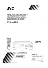
- ERRATA SHEET
- PAGE
- WARNING: TO REDUCE THE RISK OF FIRE OR ELECTRIC SHOCK, DO NOT EXPOSE THIS APPLIANCE TO RAIN OR MOISTURE
- CAUTION — POWER SWITCH
- FOR U.S.A
- CAUTION
- CAUTION: PROPER VENTILATION
- TABLE OF CONTENTS
- PARTS IDENTIFICATION
- GETTING STARTED
- BASIC OPERATIONS
- BASIC SETTINGS
- RECEIVING RADIO BROADCASTS
- USING THE DSP MODES
- COM PU LINK REMOTE CONTROL SYSTEM
- AV COMPU LINK REMOTE CONTROL SYSTEM
- OPERATING JVC'S AUDIO/VIDEO COMPONENTS
- TROUBLESHOOTING
- SPECIFICATIONS
- FRONT PANEL
- REMOTE CONTROL
- IMPORTANT
- BEFORE INSTALLATION
- GENERAL
- LOCATIONS
- HANDLING THE RECEIVER
- CHECKING THE SUPPLIED ACCESSORIES
- CONNECTING THE FM AND AM ANTENNAS
- NOTE
- NOTES
- CONNECTING THE SPEAKERS
- CONNECTING THE FRONT SPEAKERS
- CONNECTING THE REAR AND CENTER SPEAKERS
- CONNECTING THE SUBWOOFER SPEAKER
- CONNECTING AUDIO/VIDEO COMPONENTS
- ANALOG CONNECTIONS
- AUDIO COMPONENT CONNECTIONS
- IF YOUR AUDIO COMPONENTS HAVE A COMPU LINK-3 TERMINAL
- VIDEO COMPONENT CONNECTIONS
- TV AND/OR DBS TUNER
- DIGITAL CONNECTIONS
- CONNECTING THE POWER CORD
- PLUG THE POWER CORD INTO AN AC OUTLET
- CAUTIONS
- PUTTING BATTERIES IN THE REMOTE CONTROL
- TURNING THE POWER ON AND OFF (STANDBY)
- ON THE FRONT PANEL
- FROM THE REMOTE CONTROL
- SELECTING THE SOURCE TO PLAY
- SIGNAL AND SPEAKER INDICATORS ON THE DISPLAY
- SELECTING DIFFERENT SOURCES FOR PICTURE AND SOUND
- ADJUSTING THE VOLUME
- SELECTING THE FRONT SPEAKERS
- ON THE FRONT PANEL ONLY
- LISTENING ONLY WITH HEADPHONES
- MUTING THE SOUND
- FROM THE REMOTE CONTROL ONLY
- ADJUSTING THE SUBWOOFER OUTPUT LEVEL
- BEFORE YOU START, REMEMBER
- ATTENUATING THE INPUT SIGNAL
- REINFORCING THE BASS
- ADJUSTING THE TONE
- RECORDING A SOURCE
- ADJUSTING THE FRONT SPEAKER OUTPUT BALANCE
- SETTING THE SUBWOOFER INFORMATION
- CHANGING THE SOURCE NAME
- SETTING THE SPEAKERS FOR THE DSP MODES
- FRONT, CENTER, AND REAR SPEAKER SETTING
- REPEAT STEPS 1 AND 2 TO SELECT THE APPROPRIATE ITEMS FOR THE OTHER SPEAKERS
- CENTER DELAY TIME SETTING
- REAR DELAY TIME SETTING
- CROSSOVER FREQUENCY SETTING
- PRESS SETTING REPEATEDLY UNTIL "CROSSOVER FRQ" (CROSSOVER FREQUENCY) APPEARS ON THE DISPLAY
- PRESS MULTI CURSOR ◀/▶ TO SELECT THE CROSSOVER FREQUENCY LEVEL ACCORDING TO THE SIZE OF THE SMALL SPEAKER CONNECTED
- LOW FREQUENCY EFFECT ATTENUATOR SETTING
- PRESS SETTING REPEATEDLY UNTIL "LFE ATT" (LOW FREQUENCY EFFECT ATTENUATOR) APPEARS ON THE DISPLAY
- PRESS MULTI CURSOR ◀/▶ TO SELECT THE LOW FREQUENCY EFFECT ATTENUATOR LEVEL
- DYNAMIC RANGE COMPRESSION SETTING
- PRESS SETTING REPEATEDLY UNTIL "D. RANGE COMP." (DYNAMIC RANGE COMPRESSION) APPEARS ON THE DISPLAY
- PRESS MULTI CURSOR ◀/▶ TO SELECT THE APPROPRIATE ITEM ABOUT THE COMPRESSION LEVEL
- DIGITAL INPUT (DIGITAL IN) TERMINAL SETTING
- PRESS SETTING REPEATEDLY UNTIL "DIGITAL IN" APPEARS ON THE DISPLAY
- PRESS MULTI CURSOR ◀/▷ TO SELECT AN APPROPRIATE SETTING
- SELECTING THE ANALOG OR DIGITAL INPUT MODE
- PRESS ANALOG/DIGITAL REPEATEDLY UNTIL THE DIGITAL INPUT MODE YOU WANT APPEARS ON THE DISPLAY
- STORING THE BASIC SETTINGS AND ADJUSTMENTS — ONE TOUCH OPERATION
- TO STORE THE SOUND SETTINGS
- ADJUST THE SOUND USING THE FUNCTIONS LISTED ABOVE
- TO RECALL THE SOUND SETTINGS
- TO CANCEL THE ONE TOUCH OPERATION FUNCTION
- USING THE SLEEP TIMER
- PRESS SLEEP REPEATEDLY
- WHEN THE SHUT-OFF TIME COMES
- TO CHECK OR CHANGE THE TIME REMAINING UNTIL THE SHUT-OFF TIME PRESS SLEEP ONCE
- TO CANCEL THE SLEEP TIMER
- TUNING IN STATIONS MANUALLY
- PRESS FM/AM TO SELECT THE BAND
- PRESS MULTI CURSOR △ / ▽ REPEATEDLY UNTIL "- TUNING +" APPEARS ON THE DISPLAY
- PRESS MULTI CURSOR ◀/▶ UNTIL YOU FIND THE FREQUENCY YOU WANT
- USING PRESET TUNING
- TO STORE THE PRESET STATIONS
- TUNE IN THE STATION YOU WANT TO PRESET (SEE "TUNING IN STATIONS MANUALLY")
- PRESS MEMORY
- PRESS MULTI CURSOR ◀/▷ TO SELECT A CHANNEL NUMBER WHILE THE CHANNEL NUMBER POSITION IS FLASHING
- PRESS MEMORY AGAIN WHILE THE SELECTED CHANNEL NUMBER IS FLASHING ON THE DISPLAY
- REPEAT STEPS 1 TO 4 UNTIL YOU STORE ALL THE STATIONS YOU WANT
- TO ERASE A STORED PRESET STATION
- TO TUNE IN A PRESET STATION ON THE FRONT PANEL
- PRESS MULTI CURSOR ▲/▼ REPEATEDLY UNTIL “- PRESET +” APPEARS ON THE DISPLAY
- PRESS MULTI CURSOR ◀/▶ TO SELECT A PRESET CHANNEL STATION
- PRESS FM/AM
- PRESS 10 KEYS TO SELECT A PRESET CHANNEL NUMBER
- SELECTING THE FM RECEPTION MODE
- WHEN AN FM STEREO BROADCAST IS HARD TO RECEIVE OR NOISY
- D-PHONIC MODES
- DAP MODES
- HEADPHONES MODE
- SURROUND MODES
- DOLBY SURROUND (DOLBY DIGITAL AND DOLBY PRO LOGIC)
- DTS DIGITAL SURROUND
- JVC THEATER SURROUND
- AVAILABLE DSP MODES ACCORDING TO THE SPEAKER ARRANGEMENT
- ADJUSTING THE 3D-PHONIC MODES
- PRESS DSP MODE REPEATEDLY UNTIL "3D ACTION" OR "3D THEATER" APPEARS ON THE DISPLAY
- ADJUST THE EFFECT LEVEL
- PRESS SURROUND MODE REPEATEDLY UNTIL "3D ACTION" OR "3D THEATER" APPEARS ON THE DISPLAY
- PRESS SOUND
- PRESS EFFECT TO SELECT AN EFFECT LEVEL YOU WANT
- ADJUSTING THE DAP MODES AND HEADPHONES MODE
- PRESS DSP MODE REPEATEDLY UNTIL THE DAP MODE — LIVE CLUB, DANCE CLUB, HALL, PAVILION, OR HEAD PHONE — APPEARS ON THE DISPLAY
- ADJUST THE SPEAKER OUTPUT LEVELS
- ADJUSTING THE SURROUND MODES
- DOLBY AND DTS SURROUND ADJUSTMENTS
- PRESS TEST AGAIN TO STOP THE TEST TONE
- PRESS SURROUND TO ACTIVATE AN APPROPRIATE SURROUND MODE — PRO LOGIC, DOLBY DIGITAL OR DTS SURROUND
- JVC THEATER SURROUND ADJUSTMENTS
- PRESS SURROUND MODE REPEATEDLY UNTIL "THEATER" APPEARS ON THE DISPLAY
- PRESS TEST TO CHECK THE SPEAKER OUTPUT BALANCE
- PRESS DSP MODE REPEATEDLY UNTIL "THEATER" APPEARS ON THE DISPLAY
- ACTIVATING THE DSP MODES
- FOR DOLBY PRO LOGIC, DOLBY DIGITAL, AND DTS DIGITAL SURROUND
- PRESS SURROUND SO THAT THE LAMP NEXT TO THE BUTTON LIGHTS UP
- SELECT AND PLAY A SOUND SOURCE
- TO CANCEL THE DOLBY/ DTS SURROUND MODE
- PRESS SURROUND SO THAT THE LAMP ON THE FRONT PANEL LIGHTS UP
- TO CANCEL THE DOLBY/DTS SURROUND MODE
- FOR THE OTHER DSP MODES
- PRESS DSP MODE REPEATEDLY UNTIL THE MODE YOU WANT APPEARS ON THE DISPLAY
- TO CANCEL THE DSP MODE
- PRESS SURROUND MODE REPEATEDLY UNTIL THE DSP MODE YOU WANT APPEARS ON THE DISPLAY
- COMPU LINK REMOTE CONTROL SYSTEM
- REMOTE CONTROL THROUGH THE REMOTE SENSOR ON THE RECEIVER
- AUTOMATIC SOURCE SELECTION
- AUTOMATIC POWER ON/ OFF (STANDBY): ONLY POSSIBLE WITH THE COMPU LINK-3 CONNECTION
- SYNCHRONIZED RECORDING
- CONNECTIONS
- REMOTE CONTROL OF THE TV, DVD PLAYER, AND VCR USING THIS REMOTE CONTROL
- ONE-TOUCH VIDEO PLAY
- ONE-TOUCH DVD PLAY
- AUTOMATIC SELECTION OF TV'S INPUT MODE
- AUTOMATIC POWER ON/OFF
- TUNER
- SOUND CONTROL SECTION (AMPLIFIER)
- TURNTABLE
- CD PLAYER
- CD PLAYER-CHANGER
- CASSETTE DECK
- MD RECORDER
- VCR
- DVD PLAYER
- TV
- AMPLIFIER
- AUDIO
- VIDEO
- FM TUNER (IHF)
- AM TUNER
- HOW TO LOCATE YOUR JVC SERVICE CENTER
- JVC SERVICE & ENGINEERING
- COMPANY OF AMERICA
- IF YOU SHIP THE PRODUCT
- DON'T SERVICE IT YOURSELF
- ACCESSORIES
- JVC
- LIMITED WARRANTY AUDIO
- WHAT WE WILL DO
- WHAT YOU MUST DO FOR WARRANTY SERVICE
- WHAT IS NOT COVERED
Brand : JVC
Model : RX-6000VBK
Category : Receiver