
GT (2011) - Car OPEL - Free user manual and instructions
Find the device manual for free GT (2011) OPEL in PDF.


| Product Type | Sports Convertible Car |
| Brand | Opel |
| Model | GT (2011) |
| Category | Car |
| Body Style | 2-door Convertible |
| Seating Capacity | 2 |
| Length | 4100 mm (approx.) |
| Width | 1800 mm (approx.) |
| Height | 1300 mm (approx.) |
| Weight | 1300 kg (approx.) |
| Engine Options | 1.4L Turbo Petrol / 1.6L Turbo Petrol |
| Power Output | 140–200 hp |
| Transmission | 6-speed Manual or 5-speed Automatic |
| Fuel Type | Petrol (Gasoline) |
| Drive Type | Rear-Wheel Drive |
| Top Speed | 215–230 km/h (approx.) |
| Fuel Consumption (Combined) | 8.0–9.0 L/100 km |
| Brakes | Disc Brakes (Front and Rear) |
| Safety Systems | ABS, ESP, Airbags (Front and Side) |
| Maintenance Interval | Every 12 months or 15,000 km |
Frequently Asked Questions - GT (2011) OPEL
User questions about GT (2011) OPEL
0 question about this device. Answer the ones you know or ask your own.
Ask a new question about this device
Download the instructions for your Car in PDF format for free! Find your manual GT (2011) - OPEL and take your electronic device back in hand. On this page are published all the documents necessary for the use of your device. GT (2011) by OPEL.
USER MANUAL GT (2011) OPEL
Operation, Safety, Maintenance
2
Data specific to your vehicle
Please enter your vehicle's data here to keep it easily accessible.
This information is available under the section "Technical data" as well as on the identification plate.
Fuel
Designation
Engine oil
Grade Viscosity
Tyre pressure
Ty re si ze with full load Summer tyres Front Rear Winter tyres Front Rear
Weights
Permissible Gross Vehicle Weight - E C k e r b w e i g h t = Loading
Your Opel GT
is an intelligent combination of forward-looking technology, impressive safety, environmental friendliness and economy.
It now lies with you to drive your vehicle safely and ensure that it performs perfectly. This Owner's Manual provides you with all the necessary information to that end.
Make sure your passengers are aware of the possible risk of accident and injury which may result from improper use of the vehicle.
You must a lways comply with the specific laws of the country that you are tra velling through. These la ws may d iffer from the information in this Owner's Manual.
When instructed to consult a workshop, we recommend that you consult an Opel Service Partner.
All Opel Service Partners offer first-class service at reasonable ble prices.
You will receive quick, reliable and individual service.
Experienced mecha nics, trained by Opel, work according to specific Opel instructions.
The Owner's Manual should always be kept in the vehicle: Ready to hand in the glove compartment.
Make use of the Owner's Manual:
■ Its "In brief" section will give you an initial overview.
The table of contents at the beginning of the Owner's Manual and within the individual chapters will show you where everything is.
■ Its index will help you find what you want.
■ It will familiarise you with the sophisticated technology.
■ It will increase your pleasure in your vehicle.
■ It will help you to hand le your vehicle expertly.
The Owner's Manual is designed to be clearly laid-out and easily understood.
This symbol signifies:
▶ Continue reading on next page.
* The asterisk signifies equipment not fitted to all vehicles (model variants, engine options, models specific to one country, optional equipment, O pel genuine parts and accessories).
⚠ Warning
Text marked △ Warning provides information on risk of accident or injury. Disregard of the instructions may lead to injuries or endanger life. Inform your passengers acc ordingly.
Yellow arrows in the illustrations serve as points of reference or indicate some action to be p erformed.
Black arrows in the illustrations indicate a reaction or a second action to be performed.
Directional data, e.g. left or right, or front or back, in the descriptions always relates to the direction of travel.
We wish you many hours of pleasurable driving
Your O pe | Tea m
Contents
In b rief .... 6
C lim ate c ontrol .... 102
Driving and operation .... 110
Self-help, vehicle care .... 130
Service, mainte na nce.... 165
To unlock and open the doors: Press button ⏻ on remote control to unlock driver's door, pull door handle
Press button Ⓤ ag ain within 5 seconds to unlock passenger's door.
The lug gage comp artment remains closed.
▶ Door locks - see page 21,
Keys - see page 21,
Electronic imm obiliser - see page 21, Remote control - see page 22,
Central locking system - see page 24.

S 13936
To open luggage compartment: Press a nd hold button 📄 on remote control, lift luggage compartment lid towards rear of vehicle
▶ Remote control - see page 22,
Central locking system - see page 24,
Luggage compartment - see page 26,
Luggage compartment release button - see page 27,
Emergency luggage e comp artment release handle - see page 27,
Soft top - see page 31.

S 13937
To ad just sea ts: Pull handle, slide seat, release handle
▶ Seats - see page 37, Seat position - see page 38.
S 13938
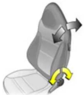
Adjusting seat backrests: Turn handwheel
Move seat backrest to suit seating position Do not lean on seat when adjusting the se at back rest.
▶ Seats - see page 37, Seat t position - see page 38.
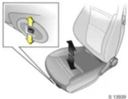
A adjusting d riv er's seat height: Press and hold switch up or down until desired position is reached
▶ Seats - see page 37, Seat position - see page 38.
8 l n b r i e f

Fitting seat belt: Draw seat belt smoothly from inertia reel, guide over shoulder, engage in buc kle
The belt must not be twisted at any point. The lap belt must lie snugly against the body.
The b ackrests must not be tilted back too far (recommended maximum tilting angle approx. 25°).
To release belt, press red button on belt buckle.
▶ Seat position - see page 38, Three-point seat belts - see page 40, Opel Full Size airbag system - see page 45.

Adjusting electrical exterior mirrors:
Four way switch in driver's door
Move switch below four way switch to left or right from centre position: four wo switch operates corresponding mirror.
▶ Further information - see page 29.

Adjusting interior mirror: Swivel mirror housing
Swivel lever on underside of mirror housing to reduce dazzle at night.
y Take care when driving with interior mirror adjusted for night vision. Rear view may be slightly distorted in this position.
▶ Further information - see page 29.
S 13842
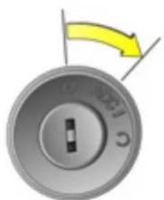
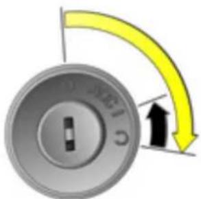
Steering column lock and ignition: Rotate steering wheel slightly, turn key to position ACC
Positions:
O = Ignition off
ACC = Steering unlocked, ignition off
I = Ignition on
C = Start
To lock the steering wheel, switch ignition off, remove key and turn steering wheel slightly until lock is engaged.
▶ Starting - see page 17,
Parking the vehicle - see page 17,
Electronic immobiliser - see page 21.

Steering wheel adjustment: Swiv el lev er down, ad just heig ht, swivel lever up, engage
Do not adjust steering wheel unless vehicle is stationary and steering column lock has been released.
Push the lever firmly upwards to ensure that the steering wheel is locked in position.
▶ Opel Full Size airbag system - see p age 45.
10 In brief
Page
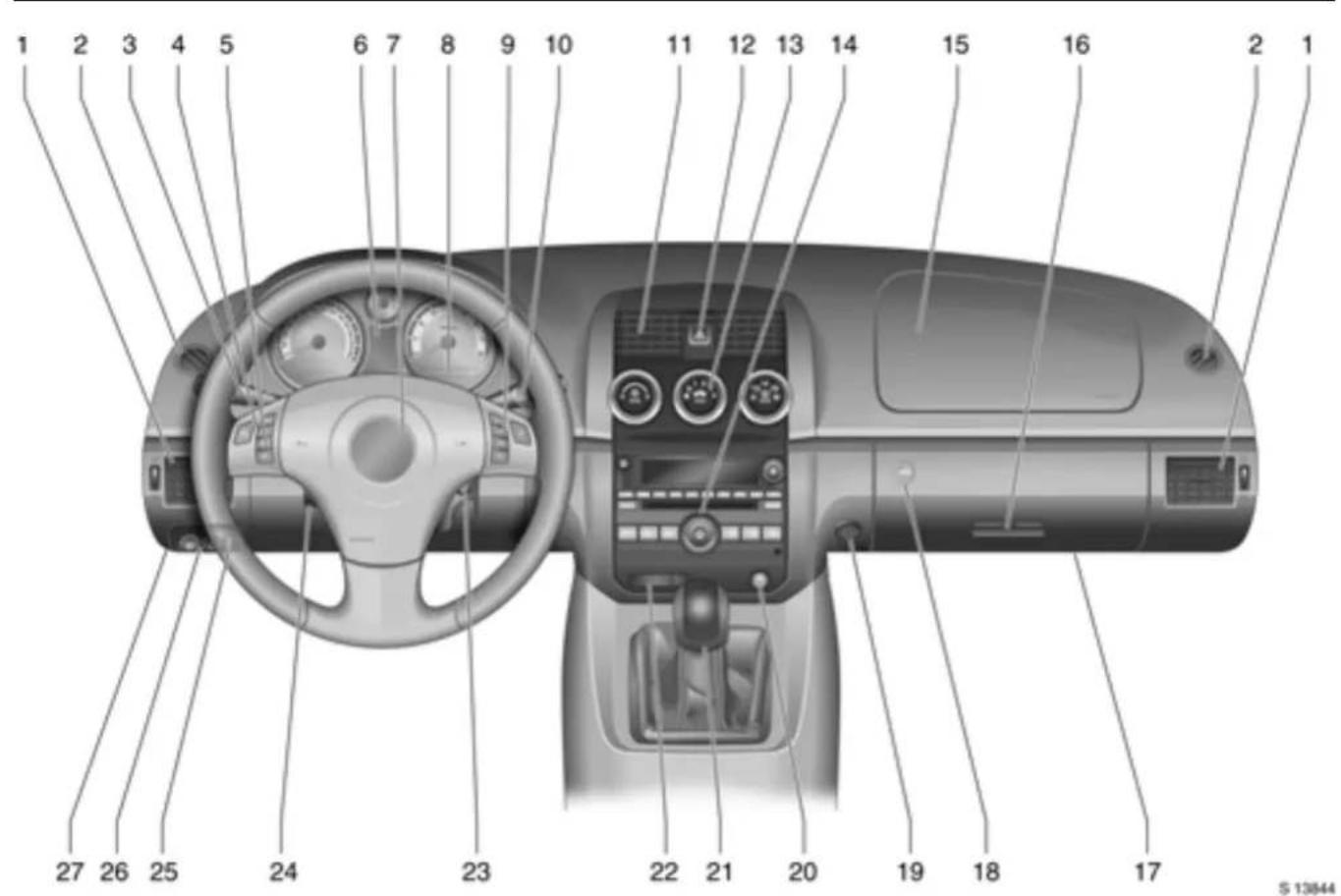
1 Side air vents 103
2 Door window defroster vents ..... 103
3 Turn signals ..... 14, 74
high or low beam ..... 13, 74
head lamp flash ..... 13, 74
parking la mps ..... 13, 73
auto light control ..... 73
4 Cruise control
rem ote control on steering wheel.. 121
5 Driver information centre
rem ote control on steering wheel....60
6 Instruments....55
7 Drive r's airb ag. .... 45
Horn .... 14
8 Drive r information ce ntre .. .... .... .... ..59
Page
9 In fotainme nt sy ste m *
remote control on steering wheel.... 79
10 Windscreen wipers,
windscreen washer system...15, 71, 72
11 Centre air vents 102
12 Hazard warning .... 14, 75
13 Climate control .... 102
14 Infotainment system*....78
15 Pa ssenge r's airbag ..... 45
16 Glove com partment.....51
17 Fuse box
(under instrument panel) ..... 143
18 Luggage e comp artment release (in g lov e com partment) .... .... .... .. 27
19 Ac cessory socke t..... 54
Page
20 ESP/Traction Control 118
21 Gear shift lever .... 16
22 Passenger's seat belt warning device .... .... .... .... .... .... .... .... 43
Seat occupancy recognition .... .... 48
23 Ignition switc h. .....9
24 S teering w heel a djustment ..... 9
25 Instrum ent panel, information display illumination ..... 76
26 Front fog lamps,
fog tail lam p ..... 13, 75
27 Bonnet release
(under instrum ent panel) ..... 130
12 In brief
Control indicators

Anti-lock Brake System (ABS): see pages 55, 124.

Lugg age comp artment open: see pages 28, 55.

Fog t ail la mp: see pages 55, 75.

Turn signals: see pages 14, 56, 74.

Hea diam p high beam : see pages 13, 56, 74.

Exhaust emissions: see pages 56, 116.

Brake system, clutch system: see pages 56, 70, 124, 156.

Engine oil pressur e: see page 57.

Cool ant temp era ture: see page 57.

Airbag systems, belt tensioners: see pages 41, 45, 57.

Driver's seat belt: see pages 39, 43, 57.

Alternator: see page 58.

Electronic Stability Program (ESP), Electronic Stability Control (ESC): see pages 58, 118.

Front fog lam ps: see pages 58, 75.

Electr oni c imm obiliser: see pages 21, 58.

Seat occupancy recognition: passenger's airbag deactivated - see page 48.

Seat occupancy recognition: passenger's airbag activated - see page 49.

Passenger's seat belt: see pages 39, 43.

S 13845
| Exterior lamps: Turn light switch
D = H i g h o r
e = Parking lamps
AUTO = Auto light control
= Auto light control off/on
▶ Headla mp warning device - see page 71, Lighting - see page 73,
Headlamps when driving abroad - see page 77.
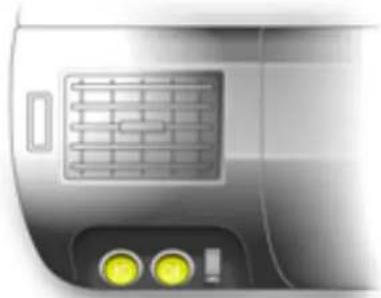
514030
Front fog lamps, fog tail lamp:
Press button b e am
知 = Front fog lamps
0‡ = Fog tail lamp
▶ Front fog la mps - see page 75, Fog tail lamp - see page 75.

S 13846
Headlamp flash, h igh and low beam:
Headlamp = Pulllevertowards flash steering wheel and release
High beam = Push lever forwards
Low beam = Pulllevertowards steering wheel
▶ High beam, headlamp flash - see page 74.
14 In brief

\$ 13847
Activate turn signals: Righ t = Move lever up Left = Move lever down
▶ Turn signals - see page 74.

Hazard warning lamps: On = Press △ Off = Press △ again
▶ Haz ard warning lamps - see page 75.

Activate horn: Press ▶ on steering wheel
▶ Opel Full Size airbag system - see page 45, Remote control on steering wheel - see page 79.
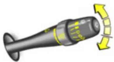
\$13850
Windscreen wipers:
Move lever from rest position
■ = F a s t
- = SI ow
= Timed interval wipe
O = Off
= Misting function
▶ Windscreen wipers - see page 71,
Adjustable wiper interval - see page 71,
Further information - see pages 163, 157.

S13851
Windscreen washer system: Press button on end of lever
Washer fluid is sprayed onto the wind screen and at the same time the wipers are operated for four cycles.
▶ W in dscre en wa sher sys te m - see p age 72,
Further information - see pages 163, 158.
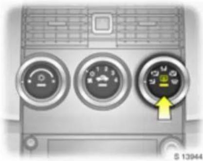
Heated rear window:
Press = On
Press again = Off
The control indicator in the button
illuminates when rear window heating is
on.
Do not turn on rear window heating when
the soft top has be en stowed in the
luggage compartment.
▶ Climate control - see page 102,
Heated rear window - see page 103.
16 In brief

Drying misted-up windows: Air distribution to 📋, rotary switches for temperature and fan to the right; press button and 🏠
Open side air vents and direct them towards the door windows.
▶ Climate control - see page 102.
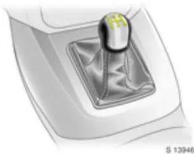
Manual transmission:
Reverse: with the vehicle stationary, engage the gear.
If the gear does not engage, set the lever in neutra I, release the clutch pedal and depress again; then repeat gear selection.
Before starting-off, check:
■ Tyre pressures and tyre condition - see pages 125, 180.
■ Engine oil level and fluid levels in engine compartment - see pages 152 to 157.
■ All windows, mirrors, exterior lighting and license plates are free from dirt, snow and ice and are operational.
■ Objects are securely located and will not be thrown forward in the event of sudden braking.
■ No objects are placed on the ins trument panel or in the area in which the airbags inflate.
■ Seats, seat belts and mirrors are correctly a djusted.
■ Brake operation.
S 13852
Starting the engine:
Transmission in neutral, depress clutch pedal fully, do not accelerate, turn key to ∅ and release
The engine cranking is computer controlled and will continue until the engine starts or up to a maximum of 15 seconds. To stop the engine cranking, turn the ignition key back to the ACC or O position.
When the fuel level is low, the controlled cranking feature is disabled to prevent engine damage. Hold the key in the position to start the engine.
Start a ttempts should not last longer than 15 seconds. If engine does not start, wait 10 seconds before repeating procedure.
To switch on ignition, only turn the key to I.
▶ Electronic immobiliser - see page 21, Further information - see pages 110 to 114.

S 13934
Releasing the hand brake: Raise lever slightly, press release button, lower lever fully
▶ Hand brake - see page 124.

S.13947
Parking the vehicle:
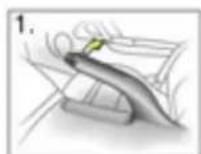
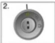
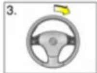
Apply hand brake firmly, switch ignition off, engage steering column lock, lock the vehicle
To lock vehicle, press button 📄.
▶ Further information - see page 21, Remote control - see page 22,
Central locking system - see page 24, Vehicle decom missioning - see page 160.
18 In brief
Advice when parking:
■ Do not the park vehicle on easily ignitable surfaces. The high temperature of the exhaust system could ignite the surface.
■ Alwa ys apply the hand brake firmly. Ap ply the hand brake as firmly as possible on uphill or downhill slopes. To reduce operating forces, depress brake pedal at the same time.
■ Close windows.
■ Before switching off ignition, engage first or reverse gear.
If the vehicle is parked on a level surface or an up hill incline, engage first gear before switching off ignition. On an uphill incline, also turn the front wheels away from the ker b.
If the vehicle is on a dow nhill incline, engage reverse gear before switching off the ignition. Also turn the front wheels towards the kerb.
■ Turn steering wheel until lock is felt to eng age (anti-theft protection), removing ignition key be for e ha nd.
■ Switch off exterior lamps, otherwise the hea clamp warning device will sound when the driver's door is opened.
■ The engine cooling fans may run after the engine has been switched off - see page 152.
▶ Further information - see pages 159 to 160.
That was the most important information for your first drive in your vehicle in brief.
The other pages of this chapter contain a summary of the interesting functions in your vehicle.
The rema in ing ch apters of the Owner's Manual contain important information on operation, safety and maintenance as well as a complete index.
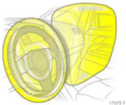
Opel Full Size airbag system
The airbag system is triggered in the event of a serious accident involving a frontal impact and forms safety cushions for the driver and passenger. The forward movement of the driver and passenger is checked and the risk of injuries to the up per body and head are thereby substantially reduced.
▶ Opel Full Size airbag system - see page 45.
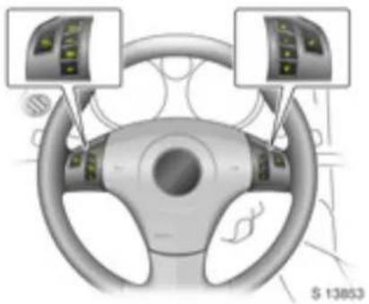
Remote control on steering wheel
The functions of the Infotainment system and the driver information centre can be operated with the buttons on the steering wheel.
▶ Driver information centre - see page 59, Remote control on steering wheel - see page 79,
In fotain me nt sy ste m * - see page 78.
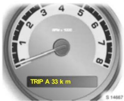
Driver information centre
Information d isplay
The information display provides information on driving data, which is continually recorded and evaluated electronically.
Functions:
■ Outside air temperature and odometer,
■ Trip odometer A,
■ Trip odometer B,
■ Fue I range,
■ Average fuel consumption,
■ Average speed,
■ Engine oil life monitor,
■ Coolant temperature,
■ Turbo boost.
▶ Information display - see page 60.
20 In brief

Check control
The check control software monitors:
■ Flu id le vels
■ Engine
■ Fuel filler cap
■ Remote control battery
Airbag sy ste ms
■ Vehicle features including cruise control, traction control and Electronic Stability Program (ESP).
▶ Check control - see page 68.
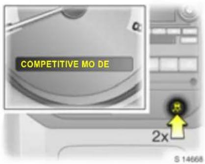
Competitive mode
To activ ate:
Press button twice within 5 seconds; "COMPETITIVE MODE" appears in the driver information centre and control indica for illuminates in the instrument panel.
Competitive mode allows the driver full control of the rear wheels. The traction control aspect of the Electronic Stability Program (ESP) is deactivated for high performance driving, while ESP continues to assist in maintaining driving stability.
▶ Driver information centre - see page 59, Check control w arning messa ge - see page 69, Electronic Stability Programme (ESP) - see page 118, Competitive mode - see page 120.
Locks, doors, windows
Replacement key 21
Car Pass * 21
Remote control .... 22
Vehicle loca tor and panic alarm .. ..... 28
Exterior mirrors..... 29
Interior mirror ..... 29
Electric windows.... 30
Soft top .... 31
Sun visors.... 36
Replacement keys
The key number is specified in the vehicle documents and in the Car Pass *.
The key is a constituent of the electronic immobiliser. Ordering keys from an Opel
Servic e Partner gua rantees problem-free op eration of the electronic immobiliser.
Ke ep the sp are k ey acces s ible in a safe place. 21
Locks - see page 164.
Car Pass *
The Car26Pass contains all of the vehicle's data and should therefore not be kept in the vehicle.
Have your Car Pass ready to hand when consulting your Opel Service Partner.

S 13854
E lectroni c imm obi lis er
The system checks whether the vehicle is allowed to be started using the key that has been inserted. If the key is re-cognise d as "authorised", the vehicle can be started. The checking takes place via a transponder in the key.
The electronic im mobiliser activates itself automatically after the key has been removed from the ignition switch.
The code number of the electronic imm ob iliser is shown in the Car Pass *.
22 Locks, doors, windows

Cont rol indica tor for im mobiliser
Illuminates briefly when the ignition is switched on.
If the control indicator stays illuminated after the ignition is switched on, there is a fault in the system; the engine cannot be started. Switch off the ignition, remove the key and repeat the start attempt pt.
If the control indicator fails to extinguish, try to start the engine using the spare key and consult a workshop.
Note
The immobiliser does not lock the doors. Therefore, after leaving the vehicle always lock it. See page 24.

Remote control
Used to operate:
■ Central locking system,
■ Luggage compartment release,
■ Vehicle locator and panic alarm.
The remote control has a range of approx. 3 m etres. This range can be affected by outside influence s.
Handle the remote control with care, protect it from moisture and high temperatures and avoid unnecessary operation.
When enabled through driver information centre personalisation mode, illumination of hazard warning lam ps indicates remote control operation.
Driver information centre - see page 59.
C entra I locking system, see page 24.
Delayed locking, see page 24.
Autom atic locking, see page 25.
Automatic unlocking, see page 25.
Luggage e compart ment release, see page 26.
Vehicle locator and pa ni c alarm, see page 28.
Welcome lig ht function, see page 67.
Fault
If the remote control does not operate correctly, it may be due to the following:
■ The range of the remote control has been exceeded.
■ Remote control battery voltage is too low. See "Remote control battery replacement".
■ Frequent, repeated operation of the remote control outside the reception range of the vehicle (e.g. too far from the vehicle, remote control is then no longer recognised). See "Radio remote control synchronisation".
■ Overloa ding the central locking system by operating at frequent intervals. The power supply may be interrupted for a short time. The system is protected by a fuse in the fuse box – see page 141.
■ Interference from higher-power r radio waves from other sources.
To eliminate the cause of the fault, cons a w orkshop.
Open driver's door with key - see page 26.

S 13956
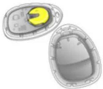
Remote control battery replacement Replace the battery in a ccordance with the cha pter "Service, Maintenance" on page 165 or when the range of the remote control begins to decrease.
Open remote control by inserting a suitable screwdriver into the notch below button ⚡ and prise apart the two halves of the remote control.
S 13955
Remove used battery, taking care to avoid touching any of the circuitry.
Replace battery - battery type, see page 181 - ensuring the new battery is installed correctly with positive (+) side facing up.
Close remote control.
Make sure that you dispose of old batteries in accordance with environmental protection regulations.
Radio remote control synchronisation
After changing the battery, unlock the door with the key in the lock. Inserting the key in the ignition switch synchronises the remote control.
24 Locks, doors, windows

Central locking system
For doors only.
To unlock:
Press button ☐ on remote control.
■ Driver's door is unlocked.
Press button ☐ on remote control twice with in 5 se cond s:
■ Passenger's door is unlocked.
When enabled through the driver information centre personalisation mode:
■ Hazard warning lam ps flash twice.
■ Horn activates twice.
If button is pressed again after the doors are unlocked, the hazard warning lamps may flash twice to indicate the doors are already unlocked.

To lock:
Close doors and windows before locking.
Press button ⏻ on remote control.
■ Both doors are locked.
When enabled through the driver information centre personalisation mode:
■ Hazard warning lamps flash once.
■ Horn activates once.
If button is pressed again after the doors are locked, the horn activates once and the hazard warning lamps may flash once to indicate the doors are already locked.
Delay ed locking :
When e na bled through the d riv er information centre personalisation mode, locking of the doors is delayed until 5 seconds after the last door is c losed, when button 🔒 is pressed on the remote control.
If a door is open when button is pressed, the hazard warning lamp will flash when the doors are locked after the delay.
To override the delay, press button ① again. Doors lock immediately.
⚠ Warning
For safety reasons, remove the key from the ignition switch before locking the vehicle.
Driver information centre - see page 59.

S 13960
Central locking switch for locking and unlocking the doors from inside the vehicle
Move switch in driver's door or passenger's door to position Ⓤ: doors are locked.
Move switch in driver's door or passenger's door to position ☐: doors are unlocked.
Note
■ If the central locking system is locked, the doors cannot be unlocked by pulling the interior handle.
■ Locked doors unlock them se lives automatically when an acc id ent of a certain severity occurs (for outside assistance), and the haz ard warning lamp s com e on. The key must also be in the ignition.
Automatic locking
The central locking system automatically locks the doors as soon as a speed of app rox. 8 km/h (5 mph) is reached.
Fault
In the event of a fault, e.g. automatic locking doesn't take place, ensure all the doors have been properly closed.
If the automatic locking function still fails to operate, we recommend that you consult a workshop.
Automatic unlocking
When e na bled through the driver information centre personalisation mode, the central locking system automatically unlocks either the driver's door or both doors when the key is turned to ignition switch position O.
This feature can also be disabled via the driver information c entre personalisation mode.
Driver information centre - see pag e 59.
26 Locks, doors, windows

Manual locking or unlocking
To unlock:
Turn key in driver's door lock towards front of vehicle as far as it will go. Turn key back to a vertical position and remove.
Both doors will be unlocked.
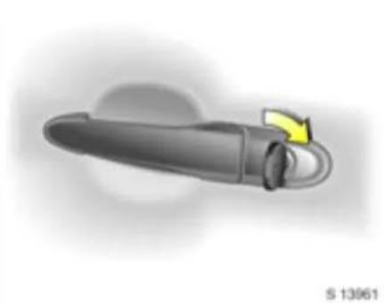
To lock:
Turn key in a river's door lock toward s rear of vehicle as far as it will go. Turn key back to a vertical position and remove.
Both doors will be locked.

Luggag e com partment
To open with remote control:
Press and hold button 📄 on the remote control.

To open with release button in glove com partment:
Key in ignition switch position O or ACC, or with hand brake app lied:
Press the luggage compa rtm ent release button located in the glove compartment.

With soft top in raised position, the buttresses are unlatched a automatically before the luggage compartment is opened. Soft top - see page 31.
Lift lug gage comp artment lid towar rds rear of vehicle to open fully.
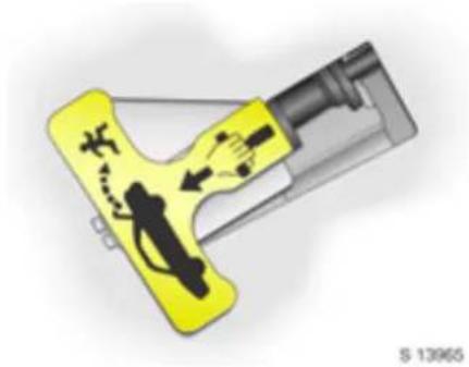
To open from within lug gage com partment:
Pull em ergenc y luggage compartm ent release handle. Push lugga ge compartm ent lid from the inside to open.
The emergency luggage compartment release handle glows in the dark for greater visibility in the event of people becoming trapped in the lug gage compartment.
Warning
Do not use the emergency luggage e compartment release handle to secure items in the lugga ge com partment, to avoid causing dama ge to the vehicle.
28 Locks, doors, windows
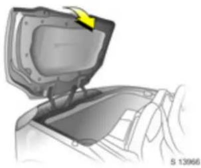
To close
⚠ Warning
Ensure the soft top is properly stowed (see page 31) and ensure no objects are placed in the area within the luggage compartment in which the soft top is stored.
To close the lug gage compartment lid, stand behind the vehicle and, with two hands laid flat on the surface of the lid, close the lid with a swift, firm motion.
If the luggage comp artm ent lid is open or is not closed properly, "TRUNK AJAR" will appear in the driver inform ation centre when the ig nition is on. Control indicator also illuminates in the instrument panel. Close luggage compartm ent lid. Driver information centre - see page 59.
⚠ Warning
Do not drive with the luggage e compartment open or ajar, e.g. when transporting bulky objects, to a void causing damage to the vehicle.
S 14031
Vehicle locator and panic alarm
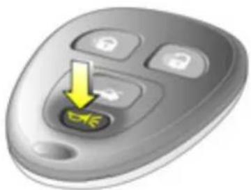
The remote control has both a vehicle locator and a panic alarm feature, activated via button ↗.
To aid location of the vehicle, e.g. when the vehicle is park ed in a car park, press and release button; the horn will sound three times and the hazard warning lamps and courtesy lamps will flash three times.
To activa te the panic alarm, press and hold the button for 3 seconds; the horn will sound and the hazard warning lam ps and courtesy lamps will flash for 30 seconds.
Press button 📋 again to switch off the panic alarm, or turn key in ignition switch to position ACC or I.
The vehicle locator and panic a la rm features are operational only with the ignition off.

Exterior mirrors
Adjust using the switches in the driver's door. Select relevant exterior mirror and adjust.

For the safety of pedestrians, the exterior mirrors will swing out of their normal mounting position if they are bumped with sufficient force. Reposition the mirror by applying slight pressure to the mirror housing.
Interior mirror
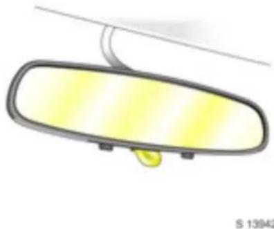
To adjust, swivel the mirror housing.
Swivel lever on underside of m irror housing to reduce d azzle at night.
Take care when driving with interior mirror adjusted for night vision. Rear view may be slightly distorted in this position.
Electric windows
⚠ Warning
Take care when operating the electric wind ows. Risk of injury, especially for children.
Vehicle passengers should be informed according ly.
Keep a close watch on the windows when closing them. Ensure that nothing becomes trapped in them as they move.
The e lect ric wind ow s can be us ed :
■ with the key in ignition switch positions ACC, I or O.
■ within approx. 5 minutes of switching key to position O
The function standby after switching off the ignition is cancelled when the driver's door is opened.

The driver's and passenger's window are operated via the switches located in the driver's door handle.
For incremental operation, briefly pull or press the switch. To open or close fully, pull or press the switch for longer.
For automatic opening, press the switch down fully. Pull the switch to stop the movement.
In the event of difficulty due to frost or the like, press the relevant wind ow sw itch h several times until the window is closed.
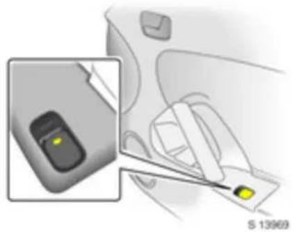
The passenger's window is operated via a switch in the door handle.
For incremental operation, briefly pull or press the switch. To open or close fully, pull or press the switch for longer.
⚠ Warning
Before leaving the vehicle, remove the ignition key in order to prevent unauthorized operation of the windows risk of injury.
Overload
If the windows are repeatedly operated at short intervals, the power supply is briefly cut off.
The system is protected by a fuse in the fuse box - see page 141.
Soft top
⚠ Warning
Take care when lowering or raising the soft top. Risk of injury. Vehicle passengers should be informed accordingly.
Keep a close watch on the moving parts when lowering or raising the soft top. Ensure that nothing becomes trapped as the soft top is moved.
Lowering soft top
Only with vehicle stationary.
With vehicle parked on a level surface, engage first or reverse gear, switch off ignition and apply hand brake.
Place no objects in the area within the lugg age compartment in which the soft top is to be stored.
Ensure that soft top canopy is dry before low ering soft top.
Open the luggage compartment - see page 26.
32 Locks, doors, windows

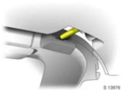
Release the locking lever located in the centre of the header rail by pulling it down and rotating it anti-clockwise. The retaining hook will unhook.

To avoid dam aging the soft top or the roof mechanism, the lever must remain in the open position during the lowering procedure.

From the side of the vehicle, pull the soft top away from the windscreen frame and fold it down into the luggage compa rtm ent.

To allow the lug gage compartment lid to close correctly, ensure the soft top is properly stowed by applying a firm, even push in the centre of the soft top.
To close the lug gage compartment lid, stand behind the vehicle and, with two hands laid flat on the surface of the lid, close the lid with a swift, firm motion.
⚠ Warning
Do not turn on rear window heating when the soft top has been stowed in the lugga ge compartment.

Raising soft top
Only with vehicle stationary.
With ve hicle p arked on a lev el s urfa ce, engage first or reverse gear, switch off ignition, apply hand brake and open the windows.
Open the luggage comp artment - see p age 26.
From the side of the vehicle, pull the soft top upwards and forwards, towards the windscreen frame.
Fully raise the soft top ensuring the alignment pins locate correctly in both sides of the windscreen frame and on each side of the body adjacent to the seat bac krests.
34 Locks, doors, windows

Ensure the retaining hook is correctly aligned within its aperture before attempting to engage the locking lever.
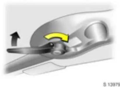
Engage the locking lever by rotating it cloc kwise and pushing it up. The retaining hook will hook into position.
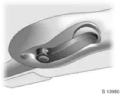
The lever must remain in the closed position when the soft top is raised.

Close the luggage compartment lid by standing behind the vehicle and, with two hands laid flat on the surface of the lid, close the lid with a swift, firm motion.
Push the two buttresses, located at the rear of the soft top, downwards.
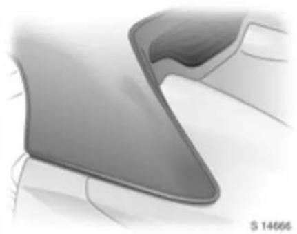
Press the buttresses into the corresponding apertures on either side of the vehicle with a swift, firm motion, ensuring they are latched correctly into the top of the lugg age compartment lid.
Warning
A clear protective film has been installed on the upper surface of the luggage compartment lid, under the buttresses. To prevent damage to the paintwork, do not remove the protective film.
Soft top care - see page 162.
36 Locks, doors, windows
§ 13996
Sun visors
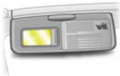
The sun visors can be folded down to protect against g la re.
The driver's sun visor includes a mirror. Slide cover to the right to use the mirror.
The m mirror cover should be c los ed while driving.
'Seats, interior
Three-point se at belts ..... 40
Child restraint systems ✦ 44
Opel Full Size airbag syste m .... ..... 45
Notes on loading the vehicle ..... 50
First-aid kit ⊕ *, warning triangle ▲ *.... 53
Power outlets ..... 53

S 13937
Seats
| Warning53 |
| Ne ver adjust se ats w hile drivin g, sincethey could move uncontrollably. |
Adjust seat in longitudinal direction
To adjust, pull handle under seat, slide seat and release handle.
Ensure seat is engaged in position before starting-of f.

S 13938
Adjust seat back rest
To adjust, turn handwheel on outboard side of seat without leaning on seat bac krest.
Move se at backrest to suit se ating position.
38 Seats, interior

Adjust driver seat height
Press and hold switch up or down until desired position is rea ched.

Seat position
Adjust driver's seat such that, with the driver sitting upright, the steer ring wheel is held in the area of its upper spokes with the driver's arm s slightly bent.
Push passenger's seat as far back as possible.
⚠ Warning
Failure to observe these descriptions could lead to injuries which could be fatal. Vehicle passengers should be informed according by before starting-off.
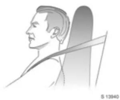
Head restraints
The head restraints are an integral part of the seat backrest and are designed to provide protection in the event of a rear impact, thereby reducing the risk of neck and shoulder injuries.

S 14034
Folding seat backrests
Lift release lever on outboard side of backrest and fold seat backrest forwards
To move upright, lift release lever, move seat backrest bac kwards and audibly engage.
Three-stage restraint system
Comprising:
■ Three-point seat belts,
■ Belt tensioners,
■ Airbag systems for driver and passenger.
The three stages are activated in sequence depending on the seriousness of the accident:
■ The automatic seat belt locking devices prevent the belt strap from being pulled out and thus ensure that the vehicle occupants are retained in their seats.
■ The seat belts are pulled down at the belt buckles. This makes the belts fit snugly, the occupants are decelerated together with the vehicle, and the body is su bje cted to les s stre ss .
■ The airbag systems are also triggered in the event of serious accidents and form a safety cushion for the occupants. Depending on the severity of the accident, the airbags inflate in two stages.
Warning
The airbag systems are supplementary to the three-point seat belts and belt tensioners, and the seat belts must therefore always be worn. Disregarding these instructions may lead to injuries or endanger life. Vehicle passengers should be informed accordingly.

Three-point seat belts
The vehicle is equipped with three-point seat belts with automatic retractors and locking devices, allowing freed on of body movement although the spring tensioned belts are always a snug fit.
For information on correct seating position – see pages 38, 42, 46.
The belts are locked during rapid vehicle acceleration or deceleration.
⚠ Warning
Always wear your seat belt, and that means also in urban traffic. It can save your life!
Also, pregnant women must always wear a seat belt – see page 43.
In the event of an accident, persons not wearing seat belts ending their fellow occupants and themselves.
Control indicator 1/2 for passenger's seat belt – see page 43.
Control indicator 4 for driver's seat belt – see pages 43, 57.
Sea t belts are only designed for use by one person at a time. They are not suitable for persons younger than 12 years of age or smaller than 150 cm.
Belt forc e li miters
Belt force limiters on the seats reduce the stress on the body due to controlled release of the belt during a collision. This means that the oc cup ants move forward under control.
Inspection of belts
Plea se check all parts of the belt system occasionally for dama ge a nd correct operation. Have da maged parts replaced . After an accid ent, have belts and dep loyed belt tensioners replaced by a workshop.
Do not perform any alterations on the belts, their anchorages, the automatic retrac tors or the belt buckles.
Make sure that belts are not da maged or trapped by sharp-edged objects.

Belt tension ers
The seat belts are fitted with belt tensioners. The seat belts are pulled down at the buckles in the event of frontal impacts above a certain severity. This tightens the belts.
Actuation of belt tensioners
Indicated by continuous illumination of control indicator ♦ in the instrument panel.
The belt tensioners must be replaced after activation. Consult a workshop.
Further information – see page 43.

Control indicator for belt tensioners
The operation of the belt tensioners is monitored electronically together with seat oc cup anc y recog nition and the airbag sy ste ms and is ind icated by co n trol indica tor ♦.
When the ignition is switched on, the control indicator flashes for approx. 5 seconds. If it does not flash, does not go out after 5 seconds or illuminates while driving, there is a fault in the belt tensioners, seat oc cup anc y recognition or the airbag systems - see a lso pag es 45, 48. The systems may fail to deploy in the event of an accident.
Deployment of the belt tensioners is indicated by continuous illumination of .
Warning
Have the cause of the fault remedied by a workshop.
The system's integrated self-diagnostics allows faults to be quickly remedied. Consult a workshop.
42 Seats, interior
Im portant
■ Accessories and other objects not specifically app roved for y our v vehicle type must not be a ffixed or placed within the action zone of the belt tensioners (near the retractor) as this could result in injury if the belt tensioners are triggered.
■ Do not make any modifications to the components of the belt tensioners, as this will render the vehicle unroadworthy
⚠ Warning
Incorrect handling (e.g. removal or fitting of b elts or belt buckles) can deploy the belt tensioners with risk of injury.
■ The belt tensioner and airbag system control electronics can be found in the centre console area. In order to avoid malfunctions, do not store magnetic objects in this area.
■ We recommend that you have the seats removed by a workshop in the event of actuation of the belt tensioners.
■ The belt tensioners are for single use only, which is indicated by continuous illumination of control indicator. Have deployed belt tensioners replaced by a workshop.
■ Applicable safety directives must alwa ys be observed when disposing of the vehicle. For this reason, disposal should be done by an a authorised recycling compa ny.

Using the belts
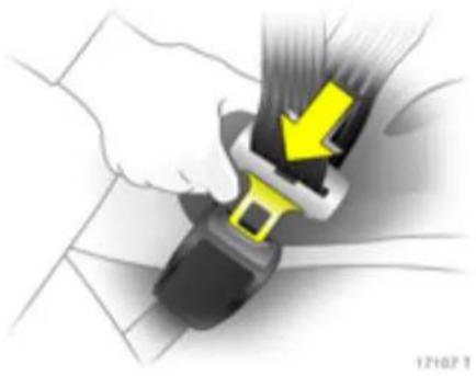
Fitting the belt
Pull the belt out from the retractor and guide it across the body, making certain that it is not twisted.
Insert the latch plate into the buckle. The seat backrest must not be tilted back too far (the recommended maximum tilting angle is approx. 25° ).
Make sure that the lap belt is not twisted and that it fits snugly across the body. Tension the belt frequently while driving by tugging the diagonal part of the belt.
⚠ Warning
On pregnant women in particular, the lap belt must be positioned as low as possible a cross the pelvis so as not to put too much pressure on the abdomen.
Thick layers of clothing prevent the belt from fitting snugly. The belt must not rest against hard or fragile objects in the pockets of your clothing (e.g. ballpoint pen, keys, spectacles), since this could cause injury. No objects such as handbags, mobile phones etc. must be present between the belt and your body.

Driver's seat belt warning device
Control indica for ≈ illuminates in the instrument panel for approx. 20 seconds when the ig nition is sw itched on, or until driver's seat belt is fastened. Flashes for a further 60 seconds if seat belt remains unfastened.
When the vehicle is being driven, if the driver's seat belt remains unfastened, the control indicator will illuminate for a pprox. 20 seconds and flash for a further 60 seconds or until the belt is fastened.
Apply seat belt - see page 42.
Control indicator goes out immediately.
Control indica for 4 for driver's seat belt see page 57.
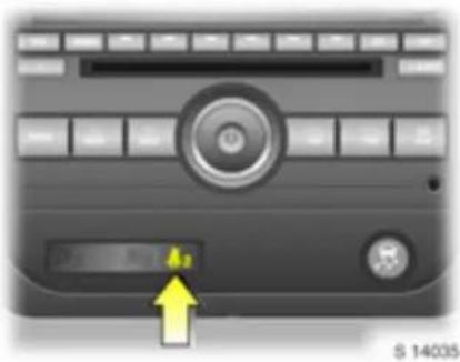
Passenger's seat belt warning device 42
Control indicator #2 illuminates in the centre console after a pprox. 20 seconds when the ignition is switched on, if passenger's seat belt is unfastened and the seat occupancy recognition system detects that the passenger's seat is occupied. Stays illuminated for a further 20 seconds then flashes for approx. 60 seconds if seat belt remains unfastened.
When the vehicle is being d riven, if the passenger's seat is occupied and the belt remains unfastened, the control indicator will illuminate for approx. 20 seconds and then flash for a further 60 second s or until the belt is fastened.
Apply seat belt – see page 42.
Control indicator goes out imm ediately.
Seat occupancy recognition - see page 48.
44 Seats, interior
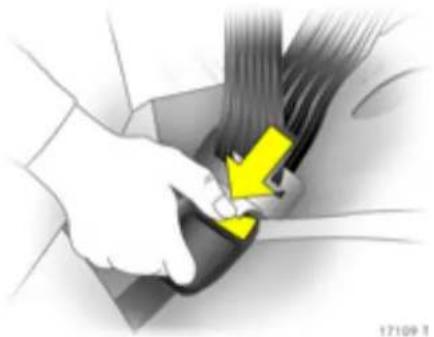
Removing the belt
To remove the belt, depress the red pushbutton on the buckle; the belt will retract automatically.
S 13967
Child restraint systems *
⚠ Warning
Vehicle with front passenger airbag: Rear-facing child seats must not be fitted, danger of fatal injury.
Specifically a proved forward-facing child restraints can be fitted on the front passenger's seat, provided that the latter is moved as far back as it will go.
Opel has approved child restraint systems from the 'DUO' and 'KID' ranges
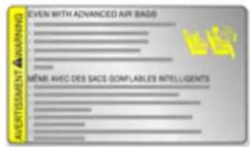
A warning sticker on the sun visors reminds that the use of rearward facing child restraint systems poses a risk of fatal inj
When using a child restraint system, always observe the instructions on installation and use.
The country in which you are travelling may not permit the use of child restraint systems on certain seats. Always comply with the local or national regulations.
⚠ Warning
Never carry c hild restraint system s on your lap, risk of fatal injury.
Not e
■ Children under 12 years or under 150 cm tall should only travel in an ap prop ria te child sa fety sea t.
■ When transporting children, use a child restraint system that is suitable for the child's weight.
■ The covers of the child restraint system can be wiped clean.
■ Do not stick anything on the child restraint systems and do not cover them with any other materials.
■ Only allow children to enter a nd exit the vehicle at the side facing away from the traffic.
■ A child restraint system which has been subjected to stress in an accident must be replaced.
Permissible options for fitting a child safety seat
| Weight and age class | On front passenger seat1) |
| Group 0: up to 10 kg or approx. 10 months | X |
| Group 0+: up to 13 kg or approx. 2 years | |
| Group I: 9 to 18 kg or approx. 8 months to 2 years | L |
| Group II: 15 to 25 kg or approx. 3 to 7 years | L |
| Group I II: 22 to 36 kg or approx. 6 to 12 years |
1) En sure seat is in its rea rmost position.
X = No child restraint of any class allowed in this seating position
L = Suitable only for specifically approved child restraints. Opel has approved child restraint systems from the 'DUO' and 'K ID' ranges.

Opel Full Size airbag system
The airbag system is identified by the wa AIRBAG on the steering wheel and above the glove compartment.
The airbag system comprises:
■ an airbag with inflator in the steering wheel and a second one in the instrument panel,
■ control electronics with impact sensors,
■ controlindicator for airbag systems ⚡ in instrument panel,
■ seat occ upa ncy recog nition.

The airbag system is triggered:
■ depending on the severity of the accident,
■ depending on the type of impact, within the range shown in the illustration.
Exception: The seat oc cup anc y recognition system deactivates the airbag on the pass en ger's side if the passen ger's se at is unoccupied – see page 48.
Examples of events triggering the airbag system:
■ Impact against a non-yielding obstacle: the a irb ags are triggered at a low vehicle speed.
■ Impact against a yielding obstacle (such as another vehicle): the airbags are only trigered at a higher vehicle speed.

When triggered, the airbags inflate in milliseconds to form a safety cushion for the d river and passenger. The forward movement of the seat occupants is checked, thereby sub stantially reducing the risk of injury to the upper body and head.
No im pairment of view will occur, because the airbags inflate and deflate so quickly that it is often not even noticed in an accident.
⚠ Warning
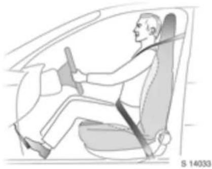
The airbag system provides optimum protection when the seat and backrest are correctly adjusted.
Adjust the driver's seat according to occupant's height such that, with the driver sitting upright, the steering wheel is held in the area of its up per spokes with the driver's arms slightly bent.
The passenger's seat should be a far back as possible, with the backrest upright – see pages 7, 37, 38.
Do not place the head, body, hands or feet on the cover of the airbag systems.
Do not place any objects in the area in which the airb ags inflate. Important information – see page 49.

⚠ Warning
The three-point seat belt must be correctly fitted (see page 42).
the The airbag system will not be triggered in the event of:
■ the ignition being switched off,
■ minor frontal collisions,
■ accidents in which the vehicle overturns,
■ collisions involving a side or rear impact where it would not be of benefit to the occupants.
⚠ Warning
Seat belts must always be worn. The airbag system serves to supplement the three-point seat belts.
If you do not wear your seat belt, you risk being seriously injured, or even thrown from the vehicle, in the event of an accident.
If an accident occurs, the belt helps to maintain the correct seat position that is required for the airbag system to provide you with effective protection.
In addition, the airbag system will not be triggered for the passenger in versions with seat occupancy recognition if:
■ the passenger's seat is unoccupied. Seat occupancy recognition – see page 48.

Control indicator for airbag systems
The operation of the airbag systems is monitored electronically together with seat occupancy recognition and the belt tensioners and is indicated by control indica tor ♦.
When the ignition is switched on, the control indicator flashes for approx. 5 seconds. If it does not flash, does not go out after 5 seconds or illuminates while driving, there is a fault in the airbag systems, the seat occupancy recognition or the belt tensioners – see also pages 41, 48. The systems may fail to deploy in the event of an accident.
Deployment of the airbags is indicated by continuous illumination of ♂.
Warning
Have the cause of the fault remedied by a workshop.
The sy stem's integrated self-diagnostics allows faults to be quickly remedied. Consult a workshop.
48 Seats, interior
Seat oc cupancy recognition
The seat occupancy recognition system deactivates the passenger's airbag if the passenger's seat is not occupied.
Control indicators H2 and H2 for seat occupancy recognition are located on the centre console. Both control indicators illuminate for approx. 5 seconds after the ignition is switched on, then either H2 or H2 illuminates continuously.
If both control indicators illuminate continuously, or neither illuminates after the ignition is switc hed on, there is a fault in the seat occupancy recognition system. The airbag and b elt tensioner systems may fail to de ploy in the event of an accident or may deploy unnecessarily. Have cause a fault remedied immediately by a workshop.
Belt tensioners - see page 41, Airbag system s - see page 45.

Control indica for ♂, illuminates continuously as soon as the system has detected that the passenger's seat is not occupied. The airbag for the passenger's seat is dea ctivated.
Pay attention to the control indicators for seat occupancy recognition.
Warning
If the passenger's seat is not occupied, control indicator 2 must illuminate continuously in the centre console after the ignition is switched on.
If control indicator 2 does not illum inate while driving, the airbag systems have not been dea ctivated on the passenger's side and may deploy unnec essarily in the event of an accident.
In this case, check that the seat backrest is not pushing down onto the seat cushion. Recline backrest if necessary. If control indicator does not illuminate after adjusting backrest, have cause of fault remedied by a workshop.
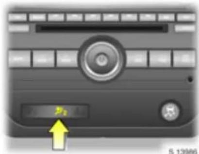
Control indicator ⚠; illuminates continuously as soon as the system has detected that the passenger's seat is occupied and the passenger is correctly seated. When a passenger occupies the passenger's seat, the airbag for the passenger's seat is activated and may inflate in the event of an accident.
Pay attention to the control indicators seat occupancy recognition.
⚠ Warning
If the passenger's seat is occupied, control ind ic ator ⚡ must illuminate continuously in the centre console after the ig nition is sw itched on.
If control indicator 2 does not illuminate while driving, the airbag systems have not been activated on the passenger's side; risk of fat to injury.
In this case, turn off the ignition, ensure the passenger's seat backrest is in an upright position and the passenger is sitting upright in the seat. Resta rt the vehicle. If the control indicator does not illuminate while driving, have cause of fault remedied by a workshop.
If control indicator for airbag systems and belt tensioners illum inates in the instrument panel and is illuminated in the centre c onsole while the pa ssenger's seat is occupied, consult a workshop immediately.
Important
■ Accessories and other objects must not be affixed or stored in the area in which the airbags inflate, since they could cause injury if the airbags are deployed.
■ Do not place any objects between the airbag systems and the vehicle occupants; risk of injury.
Warning
Never carry child restraint systems or other objects on your lap; risk of fatal injury.
■ The airbag systems and belt tensioner control electronics can be found in the centre console area. In order to avoid malfunctions, do not store magnetic objects in this a rea.
■ Do not stick anything on the steering wheel or instrument panel, or cover either of the se area s with other materials.
■ Use only a dry cloth or Interior/Upholstery Cleaner to clean the steering wheel and instrument panel. Do not use any aggressive cleaning agents.
50 Seats, interior
■ The airbag system s are triggered depending on the severity of the accident and the type of impact.
■ Each airbag can be triggered only once, which is indicated by continuous illumination of control indicator 27. Once triggered, an airbag must be replaced without delay. Consult a workshop.
■ The speeds, directions of movement and deformation properties of the vehicles, and the properties of the obstacle concerned, determine the severity of the accident and triggering of the airbags. The degree of damage to your vehicle and the resulting repair costs alone are not indicative that the criteria for triggering of the airbags were met.
■ Do not modify airbag system components, since this would render the vehicle unroadworthy.
⚠ Warning
If hand led im properly, the airbag system can be triggered in a n explosive manner; risk of injury!
■ Applicable safety directives must always be observed when disposing of the vehicle. For this reason, disposal should be done by an authorised recycling company.
■ Persons weighing less than 35 kg should only travel in a vehicle suitable for fitting a child restraint system. The use of child restraint systems in your vehicle is not rec om mended.
Do not place any heavy objects on the pass enger's se at when the se at is unoccupied, otherwise the airbag for the passenger's seat may be trig ered unnecessarily in the event of an accident.
■ To prevent malfunctions in the seat occupancy recognition system, do not use protective covers or seat cushions on the passenger's seat.
Notes on lo ad ing the vehicle
■ Secure heavy objects in the luggage compartment. If objects are to be stacked, the hea vier objects should be placed at the bottom. Unsecured objects in the luggage compa rtm ent would be thrown forward with great force in the event of heavy braking, for exam ple.
■ If heavy loads slip when the vehicle is braked heavily or driven a round a bend, the handling of the vehicle may change.
■ The warning triangle * and first-aid kit (cushion) * should alwa ys be freely accessible.
■ No objects should be placed on the instrument panel. They are reflected in the glass, obstruct the driver's view and will be thrown through the vehicle in the event of heavy braking, for example.
■ Obje cts must not be stored in the airbag inflation area, because they could cause injury if the airbag system is deployed.
■ Loads must not obstruct the operation of the pedals, hand brake and gear shift lever, or hinder the freedom of movement of the driver. Do not place any unsecured objects in the interior.
■ Do not drive with luggage compartment open when trans porting bulky objects, for example, to avoid causing damage to the vehicle.
⚠ Warning
Failure to observe these descriptions lead to injuries which may be fatal. Vehicle passengers should be informed accordingly.
\$ 13991
Stowage compartments
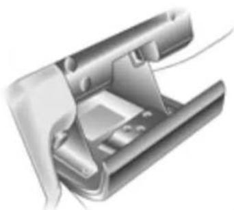
Glove compartment
To open, pull handle.
The glove compartment can be locked using the ignition key.
§ 13992
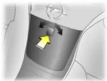
Console box between seats
To open, press button in centre of console box, rotate it left or right and pull cover down.
To close, push cover up until it latches in position and press the button.
52 Seats, interior

Net pockets
Located on the panel behind both seats.
Lift backrest release lever and fold seat forward to access the net pockets.

Backrest pockets
Located on the rear side of the backrests on both seats.
Lift backrest release lever and fold seat forward to access the backrest pockets.
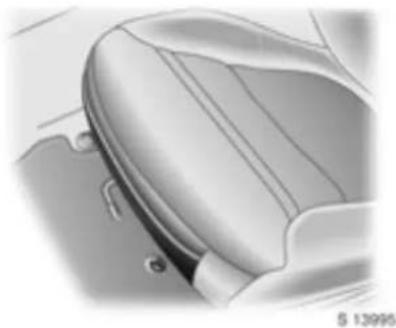
Seat cushion pockets
Located on the front of the seat cushion on both seats.

Ashtrays
To be used only for ash and not for combustible rubbish.
⚠ Warning
Failure to observe these descriptions c le ad to injuries which may be fatal. Vehicle passengers should be informed according ly.
To open: pull lid upwards.
To empy: pull ashtray out of the recess by gripping the lid and pulling upwards.
To install: seat the bottom edges of the ashtray in the recess and push the ashtray fully in.
First-a id kit ⊕ * , warning triangle Ⓐ *
Your first-aid kit and warning triangle can be accommodated in the luggage compartment.

Power outlets
Cigarette lighter
Press in cigarette lighter.
Pops up automatically once the element is heated. Pull out lighter.
The cigarette lighter socket can also be used as an accessory socket.
54 Seats, interior

S 13989
Accessory socket
Accessory sockets can be used to connect electrical accessories. The battery is discharged if the engine is not running.
Do not damage the sockets by using unsuitable plugs. The maximum power consumption of electrical accessories must not exceed 120 watts.
Do not connect any current-delivering accessories, e.g. electrical charging devices or batteries.
Electrical accessories connected to the soc ket must comply with the elec tro-mag netic compatibility requirements laid down in DIN VDE 40 839, otherwise vehicle malfunctions may occur.
If the tyre repair kit is being used, consumers must not be connected to the auxiliary socket at the same time.
*Instruments, controls
Control indicators .... 55
Instrume nt display .... 58
Drive r information centre ..... 59
Check control warning message s..... 68
Warning buzzers....71
Wind scre en wipers.... 71
Wind scre en washer system .... 72
S 13858
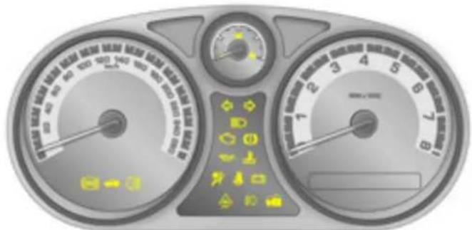
Control indicators
The control indica tors described here are not present in all vehicles. The description however, apply to all instrument versions.
The control indica tor colours mean:
■ Red Danger, important reminder,
■ Yellow Warning, information, fault,
■ Green Engagement confirmation,
■ Blue Engagement confirmation.
(ABS)
Anti-lock Brake System (ABS)
Control indicator illuminates in yellow. See page 124.

Luggag e c ompart ment open
Control indicator illuminates in yellow. See page 28.
0‡
Fog tail lamp
Control indicator illuminates in yellow. Illuminates when the fog tail lam p is on see page 75.
56 Instruments, controls
←→
Turn signals
Control indicator flashes in green.
The relevant control indicator flashes when the turn signal is on. Both control indicators flash with the hazard warning lamps on.
Rapid flashing: Failure of a turn signal lamp or associated fuse.
Turn signals - see pag es 14, 74, Change bulbs - see pag e 146, Fuses - see page 141.
ED
Headla mp high beam
Control indicator illum inates in blue.
Illuminates when high b eam is on a nd during headla mp flash – see pages 13, 74.
[NO TEXT]
Exhaust emissions
Control indica tor illuminates or flashes in yellow.
Illum inates when the ignition is switched on and goes out shortly after the engine has started.
If it illum ina tes when the engine is running:
Fault in emission control system. The permitted emission limits may be e xce ed ed. Consult a work shop.
If it flashes when the engine is running:
Fault that can lead to d estruction of the catalytic converter – see page 116. Consult a workshop immediately.
(①)
Brake system, clutch system
Control indicator illuminates or flashes in red.
Illuminates when the ignition is switched on if the hand b ra ke is applied or if the b ra ke/clutch fluid level is too low.
Flashes at speeds over 8 km/h (5 mph) if hand brake is applied.
Release hand brake before continuing journey, to avoid overheating and damaging the brake system.
Further information - see pages 68, 124, 156.
⚠ Warning g
If it illuminates when the hand brake is not applied: Stop the vehicle; interrupt your journey immediately. Consult a workshop.
S 13858

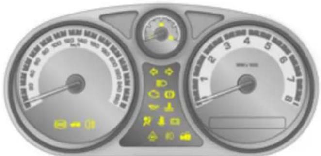
Engine oil pressure
Control indicator illum inates in red.
Illuminates when the ignition is switched on and goes out shortly after the engine has started.
If it illuminates when the engine is running: Engine lubrication may be interrupted.
This may result in damage to the engine and/or locking of the drive wheels:
- Move out of the flow of traffic as quickly as possible without impeding other vehicles.
- Depress clutch.
- Shift into neutral.
- Switch off ignition.
⚠ Warning
When the engine is off, con sid erably more force is needed to brake and steer r. Do not remove key until hicle has come to a standstill, otherwise the steering column lock could eng age unex pectedly.
Check engine oil level before consulting a workshop.

Cool ant temp era ture
Control indicator illuminates in red.
If it illuminates when the engine is running: Stop and switch off engine. Coolant temperature too high: Danger of engine damage. Check coolant level – see page 154.

Airb og s y ste m s, bel t ten ioners
Control indicator illuminates in red.
If it illuminates when the engine is running: Fault in airbag system or belt tensioners – see pages 41, 45.

Driver's seat belt
Control indicator illuminates or flashes in red.
Illumin ates for app ro x . 20 se co nd s w he n the ignition is switched on, or until driver's seat belt is fastened. Flashes for a further 60 seconds if seat belt remains unfa stened.
If seat belt remains unfastened when the vehicle is being driven, control indicator illuminates for approx. 20 seconds and flashes for a further 60 seconds.
Apply seat belt – see page 42.
Control indicator goes out immediately.
Seat belts - see page 39,
Further information - see page 43.
58 Instruments, controls
- +
Alternator
Control indicator illum inates in red.
Illuminates for a few seconds when the ignition is switched on.
If it illuminates when the engine is running: Stop and switch off engine. Battery is no being charged: Engine cooling may not be operating. Consult a workshop.
△
Electronic St abili ty Progra m (ES P), Electronic St abili ty Control (ESC)
Control indicator illum inates or flashes in yellow.
Flashing during driving:
System actively engaged - see page 118.
If it illuminates while driving:
System switched off or fault in Electronic Stability Program (ES P) – see page 118.
#0
Front fog lamp s
Control indicator illuminates in green.
Illum inates when the front fog lamps are on – see page 75.
The image is too blurry to recognize any text content.
Electronic imm obiliser
Control indicator illuminates or flashes in yellow.
If it illum ina tes when the ignition is on: Fault in the immobiliser system; the engine cannot be started - see page 21.

Instrument display
Tachom et er
Making use of the tachometer helps to save fuel; it indicates the engine speed.
Warning zone on right: maximum permissible engine speed exceeded, danger to engine.
If possible, drive in each gear in the low engine speed range (between a pprox. 2000 and 3000 rpm) and maintain an even vehicle speed.

Speedometer
Indicates the vehicle speed.

Fuel gaug e
Pointer in left zone = Fill up - see page 114.
Never run the ta nk dry!
Because of the fuel remaining in the tank, the amount of fuel required to fill the tank may be less than the specified tank capacity.

Driver information centre
Displays vehic le information and also check control warning messages when the ignition is on.
The type of information and how it is displayed depends on the settings made in personalisation mod e. Some information and warning messages appear on the display in abbreviated form.
Information display - see page 60, Personalisation mode - see page 64, Check control warning messages - see page 68.
60 Instruments, controls

Selecting functions
Functions and settings can be accessed via the d river information centre.
This is done using buttons ▶ and ◀ located on the left side of the steering wheel. The re le vant me nu options are then shown on the display one after the other.
If check control warning messages are displayed, the disp la y is blocked for other functions. Acknowledge the message by pressing button □ or ←. If there are several warning messages, acknowledge them one at a time.
Information display - see next column, Check control warning messages - see page 68.
In formation d is play
The information d isplay provides information on driving data, which is continually recorded and evalua ted electronically.
With the ignition on, press button ☐ to reach the next menu item.
Press and hold button ← to reset relevant menu items.
Some information app ears on the display in abbreviated form.
The menu items are displayed in the following order:
■ Outside air temperature and odometer,
■ TRIP A (Trip odometer),
■ TRIP B (Trip odometer),
■ FUEL RANGE (distance to empty),
■ ECON (Avera ge fuel consumption),
■ AV SPEED (Average speed),
■ O IL LIF E,
COOLANT,
■ BOOST.
When the ignition is switched off and back on a gain, the previously displayed menu item is show n.

Outside temperature and odometer
Displays outside temperature and record of total kilometres/miles driven (odometer) when the ignition is on.
With the ignition off, the odometer is presented for app rox. 10 seconds when a door is opened.

A fall in temperature is indicated immediately and a rise in temperature after a time delay.
The outside temperature is displayed in either degrees Celsius or degrees Fahrenheit (F), depending on the units of measurement chosen in personalisation mode - see page 64.
If outside tempera ture is low, "ICE POSSIBLE" appears in the disp lay as a warning for icy road surfaces.
⚠ Warning
Caution: the road surface may already be icy even before the message appears in the display.

Trip odometer
Displays d istance travelled in kilometres (k m) or miles (mi) since the last reset.
Select menu item TRIP A or TRIP B in the information display.
Both odometers can be used at the same time.
Each trip odometer can be reset to zero separately at any time.

Fuel range
Displays the remaining distance the vehicle can travel in kilometres (km) or miles (mi), based on current fuel tank contents and average fuel consumption. The display shows a verage values.
The vehicle updates the range automatically after a brief delay when the vehicle has been refuelled.
Select menu item FUEL RANGE in the information display.
The fuel range cannot be re set.
62 Instruments, controls

If the fuel level is low, a warning message "FUEL RAN GE LOW" appears in the display.
Check control warning messages - see page 68.

Average fuel consumption
Displays the average amount of fuel us in litres per 100 kilometres (L/100km) or miles per gallon (MPG), based on the distance travelled and the amount of fuel used since the last re set.
Select menu item ECON in the information display.
The measurement can be reset at any time.
Average speed
dDisplays the a verage vehicle speed in kilometres per hour (km/h) or miles per hour (mph) since the last reset.
Select menu item AV SPEED in the information display.
The measurement can be reset at any time.
Stopp ages in the journey with the ignition off are not included in the calculations.
Interrup tion of power suppl y
If the power supply has been interrupted or the battery volta ge d rops too low, the values stored in the information display will be lost.

Engine oil life monitor
Displays an estimate of the engine oil's remaining useful life as a percentage, since the last reset.
When the system has been reset after an engine oil change, the display will show 100%.
Select menu item OIL LIFE in the information display.
Engine oil life monitor - see pages 69, 151.
Cool ant temp era ture
Displays engine coolant temperature in degrees Celsius (°C) or degrees Fahrenheit (°F).
Select menu item CO OLANT in the information display.
64 Instruments, controls
![0 kPa [] OIL LIFERRESET S 14667](/content/2026/06/1312191/images/9777672fee8f5140009a156a7c714d3c628a9ada9d5f3ffe011c6ff168b04f16.jpg)
Turbo boost
Displays amount of boost the engine is currently receiving in kilopasca ls (kPa) or pounds per square inch (psi).
Select menu item BOOST in the information display.
With the ignition on and the vehicle stationary, press and hold buttons □ and ← at the same time to enter the personalisation mode.
Menu item OI L LIFE RESET will appear.
Engine oil life monitor - see pages 63, 69, 151.
Press button ☐ to reach the next menu item.
Press and hold button ← for approx. 1 second to scroll through the available settings for each menu item.
Press button ☐ to select the currently displayed setting and prog ress to the next menu item.
If no selection is made within a pprox.
10 seconds, the personalisation mode ends and the display goes back to the previously displayed information display mode.
The personalisation mode will also end immediately if the ignition is switched off.
If v vehicle spe ed ex cee ds 3 km/ h (2 m ph), only the UNITS menu will be a vailable.
Some information appears on the display in abb reviated form.
The menu items are displayed in the following order:
■ OIL LIFE RESET,
■ UNITS,
■ LOCK HO RN,
■ UNLOCK HORN,
■ LIGHT FL ASH,
■ DELAY LOCK.
■ AUTO UN LK (Un lock),
■ EXT LIGHTS (Exterior lamps),
LANGUAGE.
The default settings for these menu items were set during vehicle production.
Scroll through the available settings and select the desired setting to progress to the next menu item.
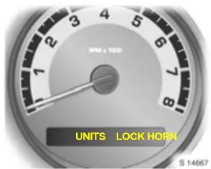
Setting units of measurement
You can select which units of measurement are to be used.
Select menu item UNITS in the personalisation mode.
Settings include "ENGLISH" and "METRIC".
When "EN GLISH" is selected, all information will be displayed in English units, e.g. d distance will be shown in miles (m i) and fuel consumption in m iles per gallon (M PG).
When "METRIC" (default) is selected, all information will be displayed in metric units, e.g. d distance will be shown in kilometres (km) and fuel consumption in litres per 100 kilometres (L/100km).
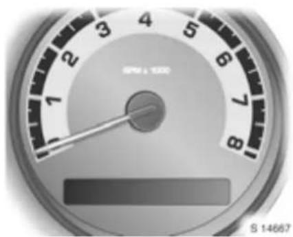
Lock horn
This feature causes the horn to sound every time button is pressed on the remote control and can be enabled or disabled.
Select menu item LOCK HORN in the personalisation mod e.
Settings include "O FF" and "ON".
When "OFF" (default) is selected, the horn will not sound on the first press of button. The horn will still sound on the second press, to confirm locking has already taken place.
When "ON" is selected, the horn will sound every time button ⓘ is p pressed.
66 Instruments, controls

Unlock horn
This fe ature causes the horn to s ound on the first press of button ☑ on the remote control and can be enab led or d isabled.
Select menu item UNLOCK HORN in the personalisation mode.
Setting s include "OFF" and "ON".
When "O FF" (de fault) is selected, the horn will not sound when button is pressed.
When "ON" is selected, the horn will sound on the first press of button 🔒.

Lig ht flash
This feature causes the hazard warning lamps to flash every time button ☐, ☑ or 📄 is presse d on the re mote control and can be enabled or disabled.
Select menu item LIGHT FLASH in the personalisation mode.
Settings include "OFF" and "ON".
When "OFF" is selected, the hazard warning lamps will not flash when button ③ or 📄 is pressed.
When "ON" (default) is pressed, the hazard warning la mps will flash every time button or is pressed.

Delayed locking
This feature delays the actual locking of the doors and can be enabled or disabled.
Select menu item DELAY LOCK in the personalisation mod e.
Settings include "O FF" and "ON".
When "O F F" is selected, the doors will lock immediately when button is pressed on the remote control.
When "O N" (d e fault) is selected, the doors will not lock until approx. 5 seconds after the last door is closed when button is pressed on the remote control.
To bypass the delay, press button 📋 again. The doors will lock immediately.
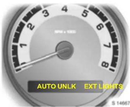
Automatic unlocking
This feature enables certa in doors to unlock automatically when the key is turned to ignition switch position O and can be enabled or disabled.
Select menu item AUTO U NLK in the personalisation mode.
Setting s include "ALL", "DRIVER" and "N ONE".
When "ALL" (default) is selected, both doors will unlock automatically.
When "DRIVER" is selected, only the driver's door will unlock automatically.
When "NONE" is selected, neither door will unlock automatically.
Central locking system - see page 24.

Welcome light functi on
This feature actuates the exterior lamps when button ☑ is pressed on the remote control. This feature can be enabled or disabled.
Select menu item EXT LIGHTS in the personalisation mode.
Settings include "OFF" and "ON".
When "ON" (default) is selected, the exterior lamps will illuminate for app rox. 20 seconds or until a door is opened when button is pressed on the remote control.
When "OFF" is selected, exterior lamps will not illuminate when button 🔒 is pressed on the remote control.
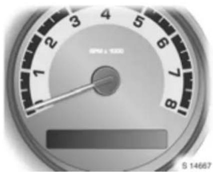
Language selection
You can select the display language for some functions.
Select menu item LANGUAGE in the personalisation mode.
Settings include "ENGLISH", "F RENCH", "S PAN ISH" and "GE RMAN".
68 Instruments, controls
The personalisation mode ends after making your language selection and the display goes back to the previously displayed menu item in the information display - see page 60.
Alternatively, press and hold buttons ▶ and ◀ at the same time to exit the personalisation mode.
Remote control - see page 22, Central locking - see page 24, Delayed locking - see page 24, Autom atic locking - see page 25, Autom atic unlocking - see page 25.
Check co ntro l warning messag es
Check control monitors several fluid levels, the remote control battery, the engine, the fuel filler cap and the status of several vehicle features including cruise control, traction control, the Electronic Stability Program (ESP) and the airbag systems.
"ESC" ap pears in some warning messages. Electronic Stability Control (ES C) is a component part of the Electronic Stability Program (ESP), im proving driving stability.
Warning messages appear in the driver information centre and a chime may sound when the message is displayed. If the re are several warning messages, they are displayed one after the other.
Some of the warning messages appear on the display in abbreviated form.
Examples of warning messages are shown on the following pages.
Ac know ledge warning messages as described on page 60. The messages will clear from the display when the condition no longer exists.
Una acknowledged warning messages will be redisplayed later if the condition still exists.

Warning messages:
AUTO LIGHTS OFF
Auto light control is disabled via the switch on the lighting lever.
AUTO LIGHTS ON
Auto light control is re-enabled via the switch on the lighting lever.
The message will only appear when a uto light control has been switched off and back on again.
It will not a ppear when the ignition is switched on.
BRAKE FLUID
Brake/clutch fluid level is low. Control indicator (①) also illuminates in the instrument panel. Top up brake/clutch fluid.
After correcting brake/clutch fluid level, have the ca us e of fluid loss reme died by a workshop.
Brake and clutch fluid level - see page 156.
CHANGE OIL SOON
Engine oil life has expired. Change engine oil.
Make an appointment with a workshop for Service work as soon as possible.
Engine oil change, eng ine oil filter change - see page 154.
Acknowledging the message by pressing button or does not reset the engine oil life monitor. See engine oil life monitor on pages 63, 151 for further information.
CO MPETI TIVE MO DE
Competitive d riv ing mode ha s b een se lecte d via button on the centre console.
Control indica tor ⚙ illuminates in the instrument panel.
Ad just your driving a cording ly.
Competitive mode - see page 120.
CRUISE ENGAGED
Cruise control has been a ctivated via the buttons located on the left side of the steering wheel.
Cruise control - see page 121.
DOOR AJAR
One or more of the doors are not closed properly. Close driver's door and passenger's door.
ENGINE DISABLED
Starting of the engine has been disabled. Consult a workshop immediately.
ESC ACTIVE
ESP has come into action, to assist driving stability in slippery road conditions. Control indicator also flashes in the instrument panel. Adjust your driving accordingly.
The message may remain for a short while after ESP assistance has ended.
Electronic Stability Program (ESP) - see page 118.
ESC OF F
E SP has been switched off via button 📄 on the centre console, or a fault is present.
Control indicator ⬆ also illuminates in the instrument panel. Adjust your driving acc ordingly.
Electronic Stability Program (ESP) - see page 118.
FUEL RANGE LOW
Fuel level is low. Fill up fuel tank.
Refuelling - see page 114.
ICE POSSIBLE
Icy road conditions are possible due to low outside air temperature. Adjust your driving according ly.
Extrem e driving conditions - see page 113.
70 Instruments, controls
KEY FOB BA TT LOW
Battery voltage of remote control is too low. Replace battery - see page 23.
LO W COO L ANT
Engine coolant level is low. Top up coolant level and have cause of loss remedied by a workshop.
Coolant level - see page 155.
LO W TR ACT IO N
Traction control has come into action, to limit wheel spin in slippery road conditions. Control indicator also flashes in the instrument panel.
Adjust your driving accordingly.
The message may rema in for a short while after trac tion control has ended.
Electronic Stability Program (ESP) - see page 118.
PAR KIN G BRAK E
The hand brake is a pplied at sp ee ds ov er 8 km/h (5 mph). Control indicator Ⓔ also flashes in the instrument panel.
Release hand brake before continuing journey, to avoid overheating and damaging the brake system.
Hand brake - see page 124.
SERVICE AIR BAG
Fault in airbag system. Control indicator also illuminates in the instrument panel. The airbags may fail to trigger in the event of an accident. Consult a workshop immediately.
SERVICE ESC
Fault in ESP. Control indicator also illuminates in the instrument panel. In slippery road conditions, the system will not assist driving stability. Adjust your driving accordingly.
If the message appears while driving, stop the vehicle and switch the ignition off and back on again. If the message still appears, consult a workshop as soon as possible.
Electronic Stability Program (ESP) - see p age 118.
SERVICE TRACTION
Fault in traction control. Control indicator also illuminates in the instrument panel. In slippery road conditions, the system will not limit wheel spin. Ad just your driving accordingly.
Consult a workshop as soon as possible.
Electronic Stability Program (ESP) - see p age 118.
TRACTION OFF
Traction control has been d eactivated via button ☑ on the centre console. Control indicator ⚙ also illum inates in the instrument panel. Adjust your driving acc ordingly.
Electronic Stability Program (ESP) - see page 118.
TRUNK AJAR
The lugga ge comp arment lid is open or is not closed p properly. Control indicator also illumina tes in the instrument panel. Close luggage compartment lid.
Do not drive with the luggage compa rtm ent open.
Luggage compartment - see pages 26, 55.
Warning buzzers
When starting the engine or while d riving:
■ if driver's seat belt is not fastened,
■ if passenger's seat belt is not fastened when the seat occupancy recognition system detects that the passenger's seat is occupied,
■ if the doors or the luggage comp arment have not be properly closed when starting-off,
■ if the hand brake is applied at speeds over 8 km/h (5 mph),
■ while operating the indicators.
When the vehicle is parked and the drive door is opened:
■ if the head lamps or parking lamps are switched on,
■ when the key is in the ignition switch,
■ if any door remains open when the doors are locked with the remote control *.
Driving hints - see page 110, Saving fuel, protecting the environment see page 112.

S13850

S14006
Windscreen wipers
To switch on, push lever upwards.
| ■ = | F | a | s | t |
| — | = | S | l | ow |
| = | Timed interval wipe | |||
| ○ | = | O | f | f |
| = | Misting function | |||
Switch to next setting up or down: gently push lever.
In case of light rain or mist, move lever downwards from position 0 to position and release: Single swipe. Hold for addition I wiping cycles. Lever returns automatically to position 0 when released.
Return the lever to its original position to switch off.
Further information - see pages 163, 157.
Adjust able wi per interval
To set the wiper interval to a value between 3 and 10 seconds:
Switch h on ignition. Move lever upwards from position O to timed interval wipe ☑.
Swivel adjustment band to the desired setting: The bars to the left of the adjustment band represent wiping frequency.
Larger bars near the top represent more frequent wiping, and the smaller bars near the bottom represent less frequent wiping.
72 Instruments, controls
With lever in position ⚪, wiping frequency is also dependent upon vehicle speed. As vehic le speed increases, wiping will become more frequent.
The wiping frequency selected via the adjustment band remains stored until it is changed again.
Further information - see pages 163, 157.
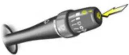
S13851
Windscreen washer system
To operate, press button ☑ on end of lever.
Washer fluid is sprayed onto the wind screen and at the same time the wipers are operated for four cycles.
Further information - see pages 163, 158.
Lighting
Exterior lamps....73
High b e am, headlam p flash. ..... 74
Turn signals.... 74
Front fog lamps #D 75
Fog tail lamp 0‡ 75
Reversing lamp .... 75
Haza rd warning lamps .... 75
Instrument illumination, information displa y illumination .... 76
Courtesy la mps .... 76
Reading lamps 76
Battery discharge protection.... 77
Lamp covers.... 77
Headlamps when driving abroad ..... 77
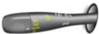
S 13845
Exterior lamps
Turn light switch:
D = High or low beam
⇒ = Parking lamps
AUTO = Auto light control
① = Auto light control off/on
Light switch to AUTO: Exterior lamps come on a automatically lly when the engine is running and if outside light conditions warrant it.
For reasons of safety, the light switch should always remain in the AUTO position.
If necessary, auto light control can be switched off; turn the light switch to position ⏻ and release. Light switch returns to AUTO position and the driver in form atio n cen tre shows "A UTO LIGH TS OFF" briefly.
Turn light switch to position ① again and release to switch auto light control back on. Light switch returns to AUTO position and the driver information centre shows "AUTO LIGHTS ON" briefly.
Auto light control will switch on automatically when the ignition is switched off and back on again.
Depending on outside light conditions, the head clamps illuminate for app rox.
20 se con ds when the key is re moved from the ignition switch.
Driver information centre - see page 59, Check control warning messages - see page 68.
Welcome lig ht function
Exterior lamp s illuminate for approx.
20 seconds or until a door is opened when the vehicle is unlocked with the remote control. See page 67.
74 Lighting
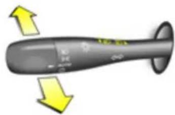
S 13846
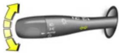
S 13847
High beam, headlamp flash
To switch from low to high beam, push lever forwards.
To switch to low beam, pull lever back towards steering wheel.
To activate the headlamp flash, pull lever towards steering wheel. The high beam switched on while activated.
The b lue control indicator 📄D illum ina tes when the high bea m or headlamp flash is on.
Turn signals
To switch on, push lever up or down.
Lever up = Right turn signal Lever down = Left turn signal
After operation, the turn signal lever returns to its starting position.
If lever is moved past resistance point, turn signal lam p remains on. When steering wheel moves back towards the straight-ahead position, turn signal lam p is automatically deactivated.
- Tap signal: Move lever to resistance point and release, to activate the turn signals when changing lanes or the like. Move lever to resistance point and hold for the turn signals to flash for long er.
Switch the turn signal off ma nually by moving the lever slightly.
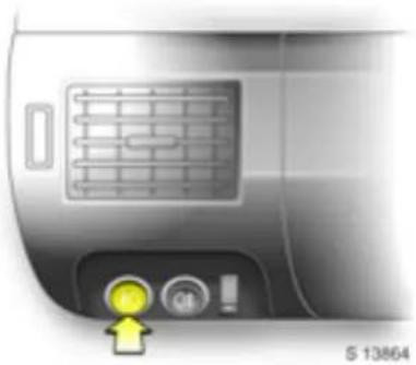
Front fog lamps 钉
On
=
Press #D, #D in
instrument panel illuminates
Off = Press 和 again or
switch ignition or parking lamps off
The fog la mps can only be switched on when both the ignition and parking lamps are on.
Follow the regulations of the country in which you are driving when using front fog lamps.
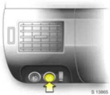
Fog tail lamp Ⓞ
On
=
Press 0‡, 0‡ in instrument panel illuminates
Off
=
Press 0 again or switch ignition or headlamps off
The fog tail lam p can only be switched on when both the ignition and headlamps are on.
Reversing lamp
Comes on when reverse gear is engaged and ignition is switched on.
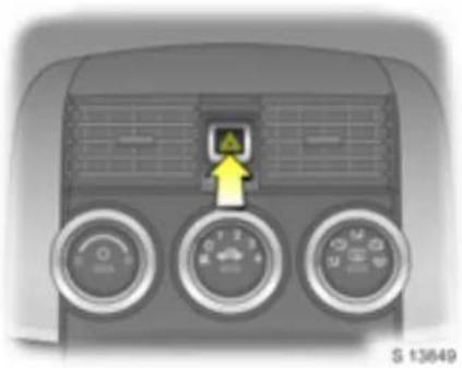
Hazard warning lamps
To switch on, push button ▲; to switch off, push button ▲ again.
To aid location of the button, the red surface is illuminated with the ignition switched on. When the button is pressed, its control indicator flashes in time with the hazard warning lamps.
76 Lighting

Instrument illumination, information display illumination
In high ambient light conditions, the auto lighting turns on the illumination with fixed intensity to indicate that the exterior lamps are on.
In most other lighting conditions, brightness can be adjusted when the ignition is on by turning adjuster wheel up or down.
When the light switch is turned to position 0 , instrument panel backlighting goes out and the driver information centre is illum inated at its maximum brightness.
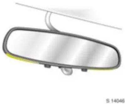
Courtesy lamps
Automatically switch on when the doors are unlocked with the remote control, when a door is opened or when the key is removed from the ignition switch.
Courtesy lamps switch off approx. 20 seconds after closing the doors and immediately when the ignition is switched on or after locking the doors with the remote control.
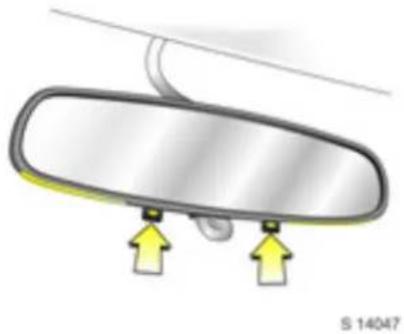
Reading lamps
Reading lamps on the left and right are individually operable.
Press button on underside of interior mirror on relevant side to switch on reading lamp. Button extends.
Press button again to switch off reading lamp. Button retracts.
Cigarette lig ht er illumina tion
Com es on when the ignition is sw itc hed on.
Luggage com part ment lighting
Comes on when the lug gage compartment is opened.
* Battery discharge protection
To prevent the battery from b ecoming discharged, the courtesy lamps, reading lamps and luggage compa rtm ent lighting switch off automatically 20 minutes after the ignition is switched off.
La mp covers
The inside of the lamp covers may mist up briefly in poor, wet and cold weather conditions, in heavy rain or after washing. The mist disappears quickly by itself; to help, switch on the la mps.
Headlamps when driving abroad
The asymmetrical dipped beam extends visibility at the edge of the road at the passenger's side. This causes glare for oncoming traffic if the vehicle is driven in countries where traffic drives on the opposite side of the road. Consult a workshop.
* Infotainment sy stem
Brief ov ervie w.... 78
Ge neural information .... .... .... .... 80
CD/MP3 player ..... 90
Ge neural advic e ..... 98
Mobile telephones and radio equipment (CB) * 101

\$ 17717
Brief overview 97
Operating elements
①. LOAD Loading discs with six-disc CD player *: Press
- or -
Setting tim e/date: Press
② FAV View and save favourite stations: Press
③ i Display additional text information for RDS stations or MP3 files: Press
④MENU Display menus
5 Display panel
6 1...6 Preset buttons 1 to 6
Select options in corresponding display panel labels
Radio: View and save favourite stations
7 EQ Select preset equalisation settings: Press
8 Adjust sound settings: Press and turn
CD: Select track; turn
Radio: Select station; turn
⑨ CAT Change category CD: Toggle between CD audio and MP3 files
⑩EJECT Eject CD: Press
⑪CD/AUX Sw itc h to CD mode/auxiliary inp ut device:Press
⑫Auxiliary input jack
⑬ FWD Fast forward during CD playback: Press and hold
14 REV Reverse during CD playback: Press and hold
15 Switch hing on and off:
Press
Volume adjustm
Turn
16 SEEK ▷ Search button
Radio: Search forwa rd s
CD: Skip forwards
⑰ SEEK◀ Search button
Radio:
Search backwards
CD: Skip backwards
18 BAND Switch on radio mode, sele ct wave band (FM, AM)
19 - CD slot

S 17718
Steering wheel remote control
Audio controls are located on the right-hand side of the steering wheel.
20— — Decrease volume
21+ + Increase volum e
22 Mute button
23 ∇ Search button
Radio:
Search backwards
CD:
Skip backwards
24 △ Search button
Radio:
Search forwards
CD:
Skip forwards
80 Infotainment system
General information
The audio system offers you state-of-the-art vehicle infotainment. The illustrations on the previous pages show the Infotainment system and the steering wheel mounted remote control buttons.
The radio has a total of 36 station memories for a combination of both wavebands (FM, AM).
The RDS (Radio Data System) functionality makes it much easier to find an FM channel and guarantees interference e-free reception. It also provides additional useful functions.
You can enjoy both audio and MP3-CDs on the integrated CD player. A six-disc CD player * is also available as an option.
The l nfotainme nt s ystem featu res Speed Compensated Volume (SCV) reg ulation. The volume regulation setting can be changed.
The sound processor offers you a range of preset equalization settings, to optimise the sound.
An enhanced, hig h-power audio am plifier and subwoofer * for the Infotainment system are available as an option.
The well-thought out design of the operating e leme nts, clearly structure d menus on the large display and a large on/volume knob enable you to operate the sy ste m e asily.
General notes on these operating inst ructions
For an overview of the different functions of the Infotainment system, see the section "Brief overview" on page 78, together with the relevant illustration, which shows all of the display and operating elements.
You can find a description of the basic steps for o pe rating the Info tainment system in these section "O per ation" on page 81.
You can find detailed functional descriptions for your Infotainment system in the sections "Radio" on page 86 and "CD/M P3 pla yer" on page 90.
Should your Infotainment system not function the way you expect it to, please read the sections "Troubleshooting" on page 97 and "General ad vice" on page 98. In many cases, this will allow you to fix a suspected fault quickly.
The section "Glossary" on page 100 explains technical terms.
The following symbols will help you to read these operating instructions easily:
A hand in front of the text asks you to perform an action.
√ A tick in front of the text identifies the Infotain me nt sy ste m's respon se.
- A bullet point in front of the text identifies additional information on the subject.
- A hyphen in front of the text marks items of a list.
A safety or warning note contains important information on how to use your Infotainment system safely. Failure to observe this information may result in a risk of damage or injury. The refore, plea se observe this information with particular care.
Im portant information on operation and road safety
Use your Infotainment system in such a way that you can always drive safely. If you have any doubts, stop the vehicle and operate the Infotainment system which the vehicle is not moving.
Theft protection
The Infotainment system is equipped with an electronic theft-deterrent feature which works by learning part of the Vehicle Identification Number (VIN).
The Infotainment system only works in your vehicle and is therefore of no value to thieves.
Retained Accessory Power (RAP)
This feature allows the Infotainment system to be played even after the ignition is turned off.
Display
The following information can be shown on the central display panel:
- Radio information,
- T i m e ,
- D a t e ,
- Sound setting s,
- C D / M P 3 i n f o
Operation
Swit ching on/off
Press the ① knob.
√ Th e Infotain me nt sy ste m s witch es on/off.
Informat ion displa yed
The illumina ted display shows information for the radio, the CD/MP3 player, time and the sound settings.
When the Infotainment system is switched on, the display illuminates and the most recently selected aud io sourc e plays at the previous volume setting.
Volume
Turn the ⏻ 15 knob; clockwise to increase the volume or anticlockwise to decrease the volum e.
- When it is switched on, the Infotainment system plays at the most recently set volume.
- The radio volume can be adjusted automatically to compensate for road and wind noise, depending on vehicle speed. See “Speed Compensated Volume (SCV)” on page 86 for further information.
m a t i o n .
Steering wheel rem ote control
The following steering wheel controls are supplied for your convenience and to improve road safety:
Buttons - 20 and + 21
Volume control
Press the plus or minus button to increase or decrease the volume of the audio source currently selected.
Button 22
Mute/unmute sound
Press the button to mute the sound.
Press again to turn the sound back on.
Buttons ▽ 23 and △ 24
Search buttons
Radio:
Press to search for next/previous station memory.
Press a nd hold for approx. 1 second to advance to next/previous station with a strong signal in the selected waveband.
CD:
Press to skip to next/previous track.
Press a nd hold for approx. 1 second to continue skipping forwards or backwards to other tracks on the disc.
Main menu
The main menu is the display that appears after the Infotainment system is switched on. The following information may be displayed:
- Waveband,
– Radio station frequency or name,
- T i m e ,
- C D / M P 3 i n f o
- Display, playback, sound or station memory labels etc..
Audio Information
The following information is shown in the display:
- Current waveband or CD.
- Current station frequency, CD track numb er or elapsed track time.
- If the RDS function is active, the station name or station call letters appear on the display. See "RDS (Radio Data System)" on page 87.
- If there is a CD in the CD slot, the "CD" symbol illuminates on the display. See "CD/MP3 Player" on page 90.
- If the CD is in random mode, the "RDM" symbol illuminates on the display. See "Random Mode" on page 94.
Ti me and da te
Display of the current time and date.
Single-disc CD player
In vehicles with a single-disc CD player, set the time and date as follows:
Turn ignition key to ACC or RUN.
Press the 15 knob.
√ The Infotainment system switches on.
Press the 1 clock button.
√ The HR, MIN, MM, DD, YYYY (hour, minute, month, day and year) labels appear on the display.
Press the appropriate button 6 located below the label that you wish to change.
Press the same button ⑥ again to increase the time/d ate.
√ The value selected increases by one (hour/minute/month/day/year) every time the same button ⑥ is pressed again.
- The value selected can also be changed using the SEEK ▷16, SEEK◀17, FWD 13 and REV 14 buttons and the ♪8 tune knob, as follows:
Press the SEEK ▷ 16 button or the FWD 13 button.
√ The value selected increases (hour/m inute /mon th/day /y ear). - or -
Press the SEEK △ button or the REV 14 button.
√ The value selected decreases (hour/m inute /mon th/day /y ear). - or -
Turn the ⑧ tune knob clockwise or anticlockwise.
√ The value selected increases or decreases (hour/minute/month/day/year).
The date does not disp la y automatically. To display the date, proceed as follows:
Press the ① clock button with the Infotainment system on.
√ The date appears.
- After a few seconds, the display reverts back to the normal radio and time disp lay.
Six-disc CD play er *
In vehicles with a six-disc CD player, set the time and date as follows:
Turn ignition key to ACC or RUN.
Press the ⏻ 15 knob.
√ The Infotainment system switches on.
Press the MENU 4 button until the set-up menu is displayed.
√ The clock option label appears on the display.
Press the appropriate button 6 located below the clock option label.
√ The HR, MIN, MM, DD, YYYY (hour, minute, month, day and year) labels appear on the display.
Press the appropriate button 6 loca ted b elow the label that you wish to change.
Press the same button ⑥ again to increase the time/date.
√ The value selected increases by one (hour/minute/month/day/year) every time the same button ⑥ is pressed again.
- The value selected can also be changed using the SEEK ▷ 16, SEEK △ 17, FWD 13 and REV 14 buttons and the ♪ 8 tune knob, as follows:
Press the SEEK ▷ 16 button or the FWD 13 button.
√ The value selected increases (hour/minute/month/day/year). - or -
Press the SEEK<17 button or the REV 14 button.
√ The value selected de cre ases (hour/minute/month/day/year). - or -
Turn the 8 tune knob clockwise or anticlockwise.
√ The value selected increases or decreases (hour/minute/month/day/year).
The date does not display automatically. To display the date, proceed as follows:
Press the MENU 4 button followed by the button 6 located below the clock option label, with the Infotainment system on.
√ The date appea rs. - After a few seconds, the display reverts back to the normal radio and time display.
C ha nging default time and date settings
The default time and date settings can be changed from a 12 hour c lock to a 24 hour clock and from the date format MM/DD/YYYY (month/day/year) to DD/MM/YYYY (day/month/year).
Change the default time or date setting s as follows:
Press the ① clock button (single-disc CD player) - or - Press the MENU ④ button (six-disc CD player *).
Press the appropriate button 6 located below the forward arrow label on the display.
√ The 12H, 24H, MM/DD/YYYY and DD/MM/YYYY labels a ppear on the disp lay.
Press the appropriate button 6 located below the label that you wish to select.
Press the ② clock button or the MENU ④ button to apply the selection.
√ The selection is applied.
- Alternatively, allow the screen to time out and the selection made will become the default time/da te setting.
Sound settings
Use the ⑧ tune knob to adjust the following sound settings:
- Bass: Low-frequency sounds,
- Midrange: Middle-frequency sounds,
- Treble: High-frequency sounds,
- Balance: Volume distribution left - right,
- Fade: Volume distribution front speakers – rear speakers.
Setting the tone
(bass/mi drange/treble)
The bass, midrange and treble tones can be a djusted to suit personal requirements. To adjust the settings, proceed as follows:
Press the ⑧ tune knob until the tone control labels appear on the display.
√ The BASS, MID and TRE Blabels appear on the display.
Press the ⑧ tune knob continuously to highlight the desired label.
- or -
Press the appropriate button 6 located below the label that you wish to select.
Turn the 8 tune knob;
clockwise to increase the level or
anticlockwise to decrease the level.
√ The highlighted setting is adjusted.
- The highlighted setting can also be adjusted using the SEEK ▷ 16, SEEK ◀ 17, FWD 13 and REV 14 buttons, as follows:
Press the SEEK ▷ 16 button or the FWD 13 button.
√ The level is increased. -
or -
Press the SEEK △ button or the REV ⑭ button.
√ The level is decreased. -
To quick kly adjust bass, midrange, or treble to the middle position, proceed as follows:
Press and hold the appropriate button ⑥ located below the BASS, MID, or TRE B label I for more than two second s.
√ A beep sounds and the level is adjusted to the middle position. - To quick kly adjust all tone and speaker controls to the mid dle position, proc eed as follows:
Press the 8 tune knob for more than two seconds.
√ A beep sounds and all tone and speaker controls are adjusted to the middle position. - If a radio station's signal is weak, or if there is static, de crea se the tre ble.
Equalizer (EQ)
A range of preset equalization settings can be selected (instead of manually adjusting the bass, midrange and treble tones), as follows:
Press the EQ ⑦ button.
√ The equalizer labels appear on the display.
Press the appropriate button 6 located below the label you wish to select.
√ The pres et e qualization setting s a re app lied.
Press the EQ 7 button again to return to the manual mode ('Manual' app ears on the dis play).
- or -
Manually adjust the bass, midrange and treble with the ♪ ⑧ tune knob to return to the manual mode.
Adjusting the speakers (balance/fade)
The volume for the driver and passenger sides, and the front and rear speaker volume can be adjusted to suit personal requirements. To adjust the settings, proceed as follows:
Press the ♪ 8 tune knob and the speaker control labels appear on the disp lay.
√ The BAL and FADE labels appear on the display.
Press the 8 tune knob continuously to highlight the desired label.
- or -
Press the appropriate button 6 located below the label that you wish to select.
Turn the ⑧ tune knob clockwise or anticlockwise to a djust the highlighted setting.
√ The highlighted setting is adjusted.
86 Infotainment system
- The highlighted setting can also be adjusted using the SEEK ▷ 16, SEEK ◀ 17, FWD 13 and REV 14 buttons, as follows:
Press the SEEK ▷ 16 button or the FWD 13 button until the desired level is obtained. - or -
Press the SEEK ◀ 17 button or the REV 14 button until the desired level is obtained.
√ The highlighted setting is adjusted. - To quickly adjust balance or fade to the middle position, proceed as follows:
Press and hold the appropriate button 6 located below the BAL or FADE label for more than two seconds.
√ A beep sounds and the level is adjusted to the middle position. - To quick kly adjust all speaker and tone controls to the mid dle p osition, proc eed as follows:
Press the ⑧ tune knob for more than two seconds.
√ A beep sounds and all speaker and tone controls are adjusted to the middle position.
Speed Compensated Volume (SCV)
To compensate for a ambient and rolling noise, the Infotainment system volume adjusts to the speed of the vehicle.
Activate/deactivate the SCV function or change the level of radio volume compensation as follows:
Set the volume to the desired level. See "Volume" on page 81.
Press the MENU 4 button until the radio set-up menu appears.
√ The 'AUTO VOLUM' option label app ears on the display.
Press the appropriate button 6 located below the 'AUTO VOLUM' option label on the display.
√ The OFF, Low, Med and High la bels app ear on the display.
Press the appropriate button 6 located below the label that you wish to select.
√ The new setting is applied.
● The display times out after approx. 10 seconds.
● Each higher setting allows for more radio volume compensation at higher vehicle speeds.
Radio
Switch on the Infotainment system Press the 15 knob.
√ The Infotainment system switches on.
√ The most recent audio source plays.
Radio mode
If you wish to listen to the radio while a CD is playing, proceed as follows:
Press the BAND 18 button.
√ The station most recently selected is disp layed.
√ The station recently selected plays.
● The CD remains in the CD slot, ready for future listening.
Select w aveba nd
√ The radio is on.
Press the BAND 18 button.
√ The radio s witches between the AM and FM wa veba nds.
√ The current waveband and the station to which the radio was tuned most recently are displayed.
√ The station recently selected plays.
● Wa veba nd selection:
- AM = Amplitude Modulation (MW),
- FM = Frequency Modulation.
Station search
Different types of search are available:
Manual station search
Stations for which the frequencies are known can be set as follows;
Turn the ⑧ tune knob; cloc kwise to search forwards or anticlock wise to search backwards, until the frequency of the required station is reached.
√ The station selected is displayed.
√ The selected station plays.
Automatic station search
Press the SEEK ▷ 16 or SEEK ◀ 17 button.
√ Radio goes to next or previous station.
Seek and scan
Press and hold the SEEK ▷ 16 or SEEK ◀ 17 button for a few seconds.
√ A beep sounds and the radio goes to the next or previous station, plays for a few seconds, then goes to the following station in the respective direction.
Press the SEEK ▷ 16 or SEEK △ 17 button again to stop the seek and scan.
√ The current station is displayed.
√ The current station play s.
- The radio only seeks and scans stations with a strong signal within the selected waveband.
Radio Data System (RDS)
RDS is a service provided by the radio broadcasters which makes it much easier to find an FM station and helps to ensure reception is free from interference.
● RDS is only possible on the FM waveband with FM stations that broadcast RDS information.
- When the radio is tuned to an FM-RDS station, the station name or call letters appear on the display.
● RDS relies upon receiving specific information from FM-RDS stations and only works when the information is available.
- In extremely rare cases, a radio station may broadcast incorrect information that causes radio features to work incorrectly. Contact the radio station in question for assistance.
Display ing a dditi ona I RDS text information
A choice of additional text information related to the current FM -RDS station can be displayed, e.g. channel, song and artist.
To display a additional text information, proceed as follows;

Press the 3 information button.
√ Additional text information labels appear on the display.
Press the 3 information button contin u o us ly to high ligh t th e desired label.
- or -
Press the appropriate button 6 located b elow the label that you wish to select.
√ The text information related to the selected label appears on the display.
- If additional text information is not available, "No Info" a ppears on the display.
Station memory
The radio has a total of 36 station memory locations for any combination of radio stations on both wavebands (FM, AM)
- The station memory locations are selected via the appropriate buttons ⑥ located below the radio station frequency labels that appear on the display.
Storing favourite ra dio stati ons
Six favourite stations are available on each of six separate pages of favourites. Each page can contain any combination of FM or AM radio stations.
By pressing the FAV ② (favourites) button continuously, each of the six separate pages of favourites can be viewed and new stations stored on any of the 36 memory locations.
To store a favourite radio station, proceed as follows;

Select wa veba nd and station.

Press the FAV 2 (favourites) button until the page where you wish to store the selected station is disp layed.

Six radio station frequency labels appear on the display.

Press a nd hold the app ropriate button ⑥ located below the label on which the selected station is to be stored.

A beep sounds and the selected station appears on the display.

The selected station plays.

Repeat the above steps for as many favourite stations as you wish to store, up to a maximum of 36 memory locations.
Changing number of favourites pages
The number of favourites pages can be set up using the MENU 4 button, up to a maximum of six separa te pag es of favourites.
To change the number of favourites pages, proceed as follows;
Press the MENU 4 button until the radio set-up menu appears.
√ The FAV 1, FAV 2, FAV 3, FAV 4, FAV 5 and FAV 6 labels appear on the display.
Press the appropriate button 6 loca ted below the label that you wish to select.
√ The selection is applied.
- Choosing the FAV 6 label will a llow up to a maximum of 36 station memory loca tions to be stored.
Press the FAV ② (favourites) button to return to the original main radio display, showing the radio station frequency labels.
√ Six radio station frequency labels appear on the display.
- Alternatively, allow the screen to time out and the selection made will be applied.
- The process for storing favourite stations for the c hos en number of favourites pages can be begun. See "Storing favourite radio stations".
Tuning into a stored radio station
To select a stored favourite radio station, proc eed as follows;
Press the FAV ② (favourites) button until the page where the favourite radio station frequency label you wish to select appears on the display.
√ Six radio station frequency labels appear on the display.
Press the appropriate button 6 located below the label you wish to select.
√ The station selected is displayed.
√ The selected station plays.
Ra dio messages
The following messages may appear on the display if a problem occurs and the radio does not operate correctly:
- Calibration Error,
- Locked.
Calibration error
The In fotainme nt sy ste m h as bee n calibrated during vehicle production. If this message appears on the display, the system has not be en ca lib ra ted corre ctly and must be returned to your retailer for service. We recommend that you consult an Opel Service Partner.
Locked
If this message appears on the display, the electronic theft-deterrent feature has locked up the radio. Take the vehicle to your retailer for service. We recommend that you consult an Opel Service Partner.
90 Infotainment system
CD/MP3 player
This device plays standard com mercial CDs with a diameter of 12 cm. You can a Iso play CDs with a dia meter of 8 cm with an adap ter.
△Contoured CDs (Shape CDs) are not suitable for playing.
Do not insert DVDs into the CD drive.
Do not add labels to a disc, as it could get stuck in the player. If a CD is recorded on a personal computer (PC), only label the disc on the top side using a marker pen.
Do not a ttempt to play scratched or damaged CDs. Only use CDs in good condition, without a label, loading them one CD at a time.
△No liability is accepted for damage to the CD drive caused by the use of unsuitable CDs or from attempting to insert more than one CD into the slot at a time.
- Audio CDs are being manufactured with mecha nisms to protec t them from unauthorised reproduction. However, these measures do not comply with the audio CD specification (Red Book) according to which a ll appliances for playing audio CDs have been and are being developed. Your Infotainment system can play back CDs with the types of copy protection known at the time the player is sold. However, this is not a g guarantee that it will be able to play b ack CDs with new variants of the copy protection mechanisms in the future.
You can also play CD-Rs and CD-RWs with MP3 music files and uncompressed CD audio files (with ".CDA" file extension) on the Infotainment system.
- While playing a CD-R or CD-RW, the sound quality may be reduced due to disc quality, the method of recording, the quality of the music that has been recorded, and the way the disc has been handled. There may be an increase in skipping, difficulty in finding tracks, and/or difficulty in loading and ejecting. If these problems occur, check the bottom surface of the disc. If the surface of the disc is damaged, e.g. cracked, broken, or scratched, the disc will not play properly.
Switch on the Infotainment system Press the ⏻ 15 knob.
√ The Infotainment system switches on.
√ The most recent audio source plays.
Playing a CD (sing le-CD player)
Insert the CD (lab el sid e up) part of the way into the CD slot 19.
√ The device pulls the CD in automatically.
● The movement of the CD must not be hindered or aided.
√ The "CD" symbol appears on the disp lay.
√ As soon as the first track starts to play, the track number appears on the disp lay.
Playing a CD (six-disc CD player *) Inserting one C D
To insert one CD into the six-disc CD player, proceed as follows;
Press and release the LOAD ① button.
√ A message appears after a few
se co nd s a sking y ou to insert the dis c.
Insert the CD (label side up) part of the way into the CD slot 19.
√ The device pulls the CD in automatically.
● The movement of the CD must not be hindered or aided.
√ The "CD" symbol appears on the display.
√ As soon as the first track starts to play, the track number appears on the display.
- If a CD is in the player when the ignition or the Infotainment system is turned off, it remains in the pla yer. When the ignition or the Infotainment system is turned on again, the CD begins playing from where it last stopped, if it was the last selected audio source.
Inserting multiple CDs
To insert multiple CDs into the six-disc CD player, proceed as follows;
Press and hold the LOAD ① button for approx. two seconds.
√ A beep sounds and "Load All Discs" app ears on the display.
Follow the on-screen instructions for inserting multiple discs, inserting the CDs label side up part of the way into the CD slot 19.
√ The device pulls the CDs in automatically.
● The movement of the CD must not be hindered or aided.
Press the LOAD 1 button a gain to cancel loading of more CDs.
√ The "CD" symbol appears on the display.
√ As soon as the first track starts to play, the track number appears on the display.
- If a CD is in the player when the ignition or the Infotainment system is turned off, it remains in the player. When the ignition or the Infotainment system is turned on ag ain, the CD begins playing from where it last stopped, if it was the last selected audio source.
CD mode
If the Infotainment system is in radio mode and you wish to play a CD, proceed as follows;
√ The Infotainment system is in radio mode.
√ A CD is already inserted in the single-CD or six-disc CD player *.
Press the CD/AUX 1 button.
√ The "CD" symbol appears on the disp lay.
√ As soon as the first track starts to play, the track number appears on the display.
- By pressing the CD/AUX 11 button again, the Infotainment system searches for an auxiliary input device, such as a portable audio player. See "Using the Auxiliary Input Jack" on page 96.
To switch back to radio mode while a CD is playing, press the BAND button.
- The CD remains in the CD slot, ready for future listening.
92 Infotainment system
Track selection
For audio CDs, the track is selected within the CD.
For MP3-CDs, the track is selected within the album selected.
If you wish to select a track while a CD/MP3-CD is playing, proceed as follows:
Turn the 8 tune knob; cloc kwise to search forwards or anticlockwise to search backwards, until the required track is selected.
√ The track starts to play and the track numb er appears on the e dis play.
Tracks can also be selected using the SEEK ▷⑯ and SEEK ◀⑰ buttons, as follows:
Press the SEEK ▷ 16 button.
√ The next track begins to play. - or -
Press the SEEK △ button.
√ The current track begins from the start, if more than 10 seconds have elapsed.
- If the SEEK ▷ 16 or SEEK ◀ 17 button is pressed continuously or pressed multiple times, the p layer continues moving forwards or backwards through the tracks on the disc.
Fast forward/backward search
To find a specific section of a track, proceed as follows:
√ You are listening to a track.
Press and hold the FWD 13 or REV 14 button.
√ Playback is advanced/reversed quickly within the track.
√ The sound is reduced during fast forwa rd/backwards searching.
Release the FWD 13 or REV 14 button when the desired section has been reached.
√ The track starts to play again at the normal volume when either button has been released.
√ The elapsed track time appears on the disp lay.
MP3-CD pla yba ck
selecting next/pr evious folder with MP3-CDs
If your MP3-CD contains several albums, you can select the album you want as follows:
√ You are listening to an MP3-CD.
√ The folder labels with < and > next to a folder icon ap pear on the disp lay.
Press the appropriate button 6 loca ted below the folder label you wish to select.
√ By selecting the < folder label, the Infotainment system goes back to the first track in the previous folder.
√ By selecting the > folder label, the Infotainment system goes to the first track in the next folder.
√ When the first track in the previous/next folder starts to play, and the relevant track information (a lbum na me, track name or artist name) appears on the display.
- All the folders which do not contain MP3 files are automatically skipped.
Switching between compressed and uncompressed audio files with MP3-CDs. The Infotainment system can play discs containing both uncompressed CD audio files (with ".CDA" file extension) and compressed audio files (MP3 files).
By default, the system reads and plays only the uncompressed audio files and ignores the MP3 files.
To switch between uncompressed and compressed files, proceed as follows;
Press the CAT ⑨ category button.
√ The Infotainment system will only read and p lay the previously ignored files.
MP3-CD music navigator Use the music navigator feature to play MP3 files on the disc in order by artist or b y album, as follows;
√ You are listening to an MP3-CD.
Press the appropriate button ⑥ located below the music navigator label ♪ on the display.
√ The Info tainment sy ste m s can s th e disc to sort the files by artist and album ID3 tag information.
- It can take several minutes to scan the disc depending on the number of MP3 files recorded on the disc. The radio may begin to play while the Infotainment system is scanning the disc in the background.
√ When the s can is finis hed, the disc begins playing again and the system defaults to playing M P3 files in order by artist.
√ The current artist playing is shown on the second line of the display between the arrows.
√ Once all songs by that artist are played, the Infotainment system moves to the next artist in alphabetical order on the disc and begins playing MP3 files by that artist.
94 Infotainment system
If you wish to listen to MP3 files by another artist, proceed as follows;
Press the appropriate button 6 located below either arrow label on the display.
√ The disc goes to the next/previous artist in alphabetical order.
Press the appropriate button 6 loca ted below either arrow button until the desired artist appears on the display.
√ Files by the selected artist are played.
To change from playback by artist to playback by album, proceed as follows;
Press the appropriate button 6 located below the 'Sort By' label on the display.
From the sort screen, press the app appropriate button 6 located below the album label on the display.
Press the appropriate button 6 located below the 'Back' label to return to the main music navigator screen.
√ The album name appears on the display - on the second line between the arrows - and tracks from the current album begin to play.
- Once all tracks from that t album are played, the Infotainment system moves to the next album in alphabetical order on the disc and begins playing MP3 files from that album.
To exit music navigation mode, press the appropriate button ⑥ located below the 'Back' label to return to normal MP3 playback.
Random mode
If you use this function, the CD/MP3 player will play back the tracks of the current disc in ra nd om order.
Single CD
To play the tracks from a single CD in random order, proceed as follows;
Press the CD/AUX 11 button to enter CD mode.
- or -
Insert the C D (lab el sid e up) p art of the way into the CD slot 19.
√ The device pulls the CDs in automatically.
● The movement of the CD must not be hindered or aided.
√ An 'RDM' label appears on the d isplay.
Press the appropriate button 6 located below the RDM label until "Random Current Disc" appears on the disp lay.
√ The tracks of the current disc are played in random, rather than sequential order.
- Switch off random play by pressing the appropriate button ⑥ loca ted b elow the RDM label a gain.
Multi ple CDs *
To play the tracks from all discs loaded in the six-disc CD player in random order, proceed as follows;
Press the CD/AUX ⑪ button to enter CD mode - or - press and hold the LOAD ① button for approx. two second s.
√ A beep sounds and "Load All Discs" appears on the display.
Follow the on-screen instructions for inserting multiple discs, inserting the CDs label side up part of the way into the CD slot 19.
√ The device pulls the CDs in automatically.
● The movement of the CD must not be hindered or aided.
Press the LOAD 1 button again to cancel loading of more CDs.
√ An 'RDM' label app ears on the display.
Press the appropriate button 6 loca ted below the RDM label until "Randomize All Discs" appears on the display.
√ The tracks of all discs loaded in the six-d isc CD player are played in ra nd om, rather than sequential order.
- Switch off random play by pressing the appropriate button 6 located below the RDM label again.
Changing the display type displaying ad ditiona I MP3-CD text infor mation
Depend ing on the kind of disc (MP3-CD with or without ID3 tags), a choice of additional text information related to the current MP3-CD can be displayed, e.g. Song, Artist and CAT (category).
To display additional text information, proceed as follows;
Press the ③ information button.
√ Additional text information labels appear on the display.
Press the 3 information button continuously to highlight the desired label.
- or -
Press the appropriate button 6 located below the label that you wish to select.
√ The text information related to the selected label appears on the display.
- If a additional text information is not available, "No Info" appears on the display.
See “Switching between compressed and uncompressed audio files” on page 93 for further information on categories.
Ejecting CDs
To eject the CD that is currently playing, proceed as follows;
Press the EJECT 10 button.
√ A beep sounds and "Ejecting Disc" appears on the display.
√ Once the disc is ejected, "Remove Disc" appears on the display.
Remove the disc from the p la yer.
- If the disc is not removed, after several seconds it is automatically retracted and begins to play.
- or -
With the six-disc CD player *, press and hold the EJECT 10 button for two seconds.
√ All disc s a re e jected.
Remove the discs from the six-disc CD player. - If the discs are not removed, after several seconds they are automatically retracted.
CD m messages
The message 'CHEC K DISC' a pears on the display if a problem occurs and the CD player does not operate correctly.
If this message appears or if the CD is ejected automatically, it could be for one of the following reasons:
- The CD is dirty, scratched, wet, or up side down.
– The air is very humid. If so, wait app rox. one hour and try again.
– There may have been a problem while burning the CD.
– The label may be caught in the CD player. - It is very h o When the temperature returns to normal, the CD should play.
- You are driving on a very rough road. When the road surface becomes smoother, the CD should play.
If the CD is not playing correctly, for any other reason, try a known good CD.
If any error occurs repeated ly or if an error cannot be corrected, we recommend that you consult an Opel Service Partner.
If the radio displays an error message, write it down and provide it to your retailer when reporting the problem.
Using the auxiliary input jack
Your Infotainment system has an auxiliary input jack 12 located on the lower right side of the Entertainment Head Unit (EHU).
This is not an audio output; Do not plug headphones into the auxiliary input jack 12.
You can however, connect an external audio device such as a laptop computer *, MP3 player *, CD changer *, or cassette player *, to the auxiliary input jack 12 for use as another audio source.
To use a portable audio player, connect a 3.5 mm phone plug to the auxiliary input jack 12 .
t .
When a device is connected, to begin playing audio from the device through the vehicle's speakers, proceed as follows;
√ You are listening to a CD/MP3.
Press the CD/AUX 1 button.
√ Audio from the external audio device connected starts to play.
- If a portable audio player is not connected, "No Input Device Found" appears on the display.
- If the volume of the connected portable aud io player does not go as loud or soft as you wish using the ⏻ 15 knob (see page 81), you may need to make additional volume adjustments on the portable aud io player itself.
To switch back to the CD/MP3 you were playing, press the CD/AUX button again.
To switch to radio mode while a portable audio device is playing, press the BAND 18 button.
- The portable audio device continues to play, so you may wish to stop it or turn it off.
Troubleshooting
If your Infotainment system does not function as you would expect, plea se read these Operating Instructions ca refully and go through the following checklist be fore contacting Customer Services.
If you cannot find a solution to the problem, we recommend that you co an Opel Service Partner.
| Error message / symptom Possible cause / remedy | |
| General | |
| Display is dark. Vehicle's battery is weak (if operated without the engine running);See page 159. | |
| Display is difficult to read. Instrument illumina tion is set incor rect ly; See page 76. | |
| Infotainment system cannot be switched on either with the Infotainment system fuse or vehicle fusebox is defective. | |
| ○ 15 knob or with the ignition key. | |
| # and correct time on the disp lay Set time as specified on page 82. | |
| Audio | |
| Audio playback volume constantly decreases and cannot be adjusted Infotainment system is overheating. Internal temperature regulator is ac ti ng to protect the Infotainment sy ste m.Recommendation: sw itch the Infotainment system off. | |
| Stored sta tion cannot be selected with the appropriate but h. | No re cept ion for st ati on curr ent ly. |
| Stored station not stored with station name. | Broa dcast ing or ganisa tion oc casionally sends add ilional inf ormation.Try t o store it a gain when the station name appears on the disp lay.Poor reception when storing (frequency is displayed).Broadcasting organisation is not transmitting RDS information(frequenc y is disp layed). |
| “CHECK DIS C” appears on the display. | After loading a CD:CD incorrectly inserted. CD label may be caught in the player.Incompatible audio CD inserted (DVD etc.).CD sc ratched or at herwise da maged.Insert an unda maged, compatible CD with t he pr inted side upwa rds. |
| During CD playback:Temperature of Infotainment system too high.Wait until the temperature of the unit has returned to normal.Air is too humid. Wait for conditions to improve.Road sur fac e is uneven. When r oad sur face becomes smoother, CD should play again. | |
| “Ca libration Error” ap pear s on t he display Infotai nme nt syste m has not been cal i brote d cor rect ly. Ret um vehic le to your retailer for service. | |
| “Locked” appears on the display. | Electronic theft-deterrent feature has locked up the Infotainment syst em. Re tum v ehi cl e to y our retailer for serv ice. |
| An ejected CD that has not been accepted is r etrac ted again by the unit when the ignition/unit is switched off. | No error.Remove the CD before switching off the ignition/ Infotainment system. |
98 Infotainment system
General advice
During normal radio reception, you may experience frequency interference and static if items such as mobile phone chargers, vehicle convenience a accessories, and external electronic devices are plugged into the accessory power socket.
If there is interference or static, unplug the item from the accessory power outlet.
FM reception
Despite a high degree of technical perfection, reception in vehicle radio sets is different from that in home radio sets and some interference may occur, even with FM-RDS stations.
Tall buildings or hills can interfere with FM signa ls, causing sound to fade in and out.
FM stereo will give the best sound, but FM signals will reach only approx. 16 to 65 km (10 to 40 miles).
AM reception
The range for most AM stations is greater than for FM, especially at night. The longer range can cause station frequencies to interfere with each other. For better radio reception, most AM radio stations will boost the power levels during the day, and then reduce these levels during the night.
Static can a Iso occur when events such as storms interfere with radio reception. When this happens, try reducing the treble on your Infotainment system.
Hand ling C Ds
Handle CDs carefully. Avoid leaving fingerprints on the CDs when changing them. Re place CDs in their cases immediately after removing them, to stop them from getting damaged, dusty and dirty.
Dirt and liquids on CDs may make the Infotainment system's CD play er lens dirty and result in m a functions.
Do not expose C Ds to he at or dire ct sunlight.
The CD player scans the bottom surface of the disc. If the surface of a CD is damaged, e.g. cracked, broken or scratched, the CD will not play properly or not at all.
If the surface of a CD is soiled, take a soft, lint-free cloth or dampen a clean, soft cloth in a mild, neutral detergent solution mixed with water, and clean it. Make sure the wiping process starts from the centre, going out towards the edge of the disc.
Do not touch the bottom side of a CD while handling it; this could damage the surface. Pick up CDs by grasping the outer edges or the edge of the hole and the outer edge.
Ca re and ma intena nce
Your Infotainment system has been developed and manufactured with great care and it should also be treated with care.
Observing the recommendations listed below will prevent your warranty from expiring prematurely and ensure that you will be able to enjoy your product for many years.
Note the following when using your Infotainment system:
- Never try to open the Infotainment system. Incorrect handling can damage the Infotainment system.
- Do not use aggressive chemicals, cleaning liquids or agents to clean the In fotain me nt sy ste m. Us e a soft cloth moistened with a mild soap solution to clean your Infotainment system.
- Do not attempt to clean the CD player using CD lens cleaners. The lens of the CD optics may become contaminated with lubricants from the CD lens cleaner.
- Do not paint or colour the Infotainment system. Paint can make moving parts sticky and stop them functioning correctly.
- Do not store combust tib le liquids, gas es or explosives in the same room as the Infotainment system, its parts or accessories.
- The Infotainment system should only be serviced by experts. Incorrect installation or servicing of the Infotainment system can have dangerous consequences and result in the warranty becoming void.
Fixed mast antenna
Check o cca sion ally to make sure the mast is still fixed tightly to the vehicle. If tightening is required, tighten by hand.
Glossary
Automatic station search
Station search v ia the seek buttons.
Balance
Volume distribution between the left and right speakers.
Bass
Low-frequency sounds.
Equalizer (E Q)
Preset equalization settings for bass, midrange and treble tones.
Fade
Volume distribution between the front and rear speakers.
ID3 tag
Code in an MP3 file which can include the following data:
- Track title,
- A r t i s t n a m e
- Track number and playing time,
- A l b u m n a m e
This information can be stored in the MP3 file with a PC.
Manual station search
Station search via the tune knob.
MP3
CD audio da ta compression method developed by the Fra unhofer Institute.
Compression allows reduction of the data to a small percentage of the original volume with without audible losses in sound quality.
If low bit rates are used to convert the audio data into MP3, smaller files are possible but sound quality is reduced.
Musi c navigator
To play MP3 files on a disc in order by artist or by album.
Random mode
CD/M P3 tracks on a single CD or from multiple CDs in the six-disc CD player * are played in a random order.
RDS (Radio Data System)
RDS is a service provided by the radio broadcasters which makes it much easier to find an FM station and helps to ensure reception is free of interference.
RDS stations are identified by the name of the station on the display instead of the frequency.
RDS stations transmit information which is automatically evaluated by the RDS radio if RDS is activated.
Speed C compensated Volume (SCV)
To compensate for ambient and rolling noise, the Infotainment system volume adjusts to the speed of the vehicle.
Seek and scan
Search and brief playback of stations with a strong signa I via the seek buttons.
Treble
High-frequency sounds.
Radio reception
Ca r radio reception differs from domestic radio reception:
As the vehicle antenna is relatively near the ground, the broadcasting companies cannot guarantee the same quality of reception as obtained with a domestic radio using an overhead antenna.
■ Changes in distance from the transmitter,
■ Multi-path reception due to reflection and
■ Shadowing
may cause static, noise, distortion or loss of reception altogether.
Mo bile teleph ones and radio eq ui pment (CB) *
The Opel installation instructions and the opera ting guid elines provided by the telep phone ma nufacturer must be ob served when fitting and opera ting a mobile telephone. Failure to do so could invalidate the vehicle's operating permit (EU Directive 95/54/EG).
Prerequisites for fault-free operation:
■ Professionally installed exterior antenna to obtain the maximum range possib le,
■ Maximum transmission power 10 Watts,
■ Installation of the telephone in a suitable spot (see information on page 49).
Obtain advice on predetermined installation locations for the external antenna and equipment holder and ways of using devices with transmission power of more than 10 Watts.
Operation of a handsfree attachment with no outside antenna, using the mobile telephone standards GSM 900/1800/1900 and U MTS, may take place only if the maximum transmission power of the mobile telephone does not exceed 2 W, in the case of GSM 900, and otherwise 1 W. The operating instructions of the manufacturer of the telephone and handsfree attachment must be noted in all cases.
For reasons of safety, we recommend that you do not use the phone while driving. Even use of a hands-free set can be a distraction while driving. Be sure to observe any country-specific regulations.
Warning
When used in the vehicle interior, mobile telephones and radio equipment (CB) with integrated antenna may cause malfunctions in the vehicle electronics.
Mobile telephones and radio equipment (CB) should only be used with an antenna fitted on the vehicle exterior.
Climate control
Heating, ventilation and
air conditioning system .... 102
Air ve nts .... 102
Heating, ventilation and 40P conditioning system
Ventilation, heating and cooling are combined into one unit that is designed to provide comfort for the season, weather or outside temperature.
When cooling is activated, the air is cooled and dried.
The heating unit heat is the air as required in all operating modes depending on the position of the temperature rotary switch. The air supply can be adjusted to suit requirements by means of the fan.
Air conditioning system – see page 107.
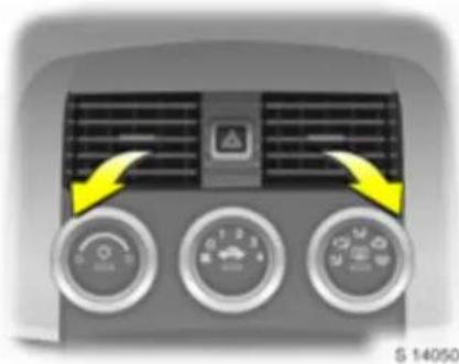
Air vents
Pleasant ventilation of the interior is controlled by the position of the temperature rotary switch.
To increase the air supply, switch the fan to a higher setting and set the air distribution rotary switch to or.
Centre air vents
Direct the flow of air by tilting and swivelling the slats.
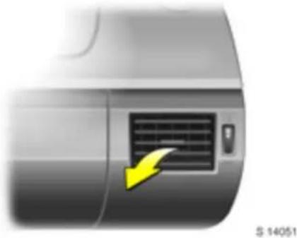
Sid e a ir vents
Open vent: rotate vertical adjuster wheel upwards.
Direct the flow of air by tilting and swivelling the slats.
Close vent: rotate vertical adjuster wheel downwards.
Additional air vents
Below the windscreen and door windows and in the foot well.

Heated rear window
With the ignition on, the rear window heating is sw itched on by pressing button ☐:
Control indica tor in button illuminates: rear window heating.
Control indica tor does not illuminate: rear window heating is switched off.
Heating works with the engine running and is switched off automatically after a pprox. 15 minutes.
If button ☐ is pressed again after switching off automatically, rear window heating will continue for app rox. 8 minutes and switch off again.
Turn rear window heating off as soon as rear vision is clear.
Warning
Do not turn on rear window heating when the soft top has been stowed in the lug gage compartment.
104 Climate control

Heating and ventilation system Left-hand rotary switch: Temperature
Turn right = Warm
Turn left = Cold
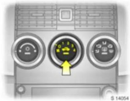
Centre rotary switch: air flow Four fan speeds:
0 = Off
4 = Maximum air flow
The rate of air flow is determined by the fan. The fan should therefore also be switched on during a journey.

Rig ht-hand rotary switch: Air distribution
To head area via adjustable centre and side air vents
To head area via adjustable centre and side air vents and to foot well
To foot well
To the windscreen,
door windows and to foot well
To the windscre en and door windows
Intermediate settings are possible.
Open the side air vents when the rotary switch is set to → or → .

Ventilation
For maximum ventilation in the head area: move air distribution rotary switch to ↗, open side air vents and move slats of centre air vents to a n upright position – see page 102.
■ Set the tem perature to the desired setting.
■ Set the fan to the desired setting.
■ For ventilation to foot well: set air distribution rotary sw itc h to ♦.
■ For simultaneous ventilation to the head area and the foot well: set air distribution rotary switch to ⚫.
Hea ting
The amount of heat is dependent on the coolant temperature and is thus not fully attained until the engine is warm.
For rapid warming of the passenger compartment:
■ Set air distribution rotary switch to the desired position, preferably position - see page 104.
■ Turn the temperature rotary switch clockwise as far as it will go.
■ Select fan setting 3.
■ Open side air vents.
The c om fort and general well-being of the vehicle occupants are to a large extent dependent on a suitable ventilation and heating setting.
On order to achieve temperature stratification with the pleasant effect of "cool head and warm feet", turn the air distribution rotary switch to ☐ or ☑ and move the temperature rotary switch to any position (in the mid-range with temperature stratification).
106 Climate control

Heating the foot well
■ Set air distribution rotary switch to ⬆.
■ Temperature rotary switch in right zone.
■ Switch on fan.

Dem isting and defrosting window s
⚠ Warning
Failure to follow the instructions can lead to window fogg ing or icing and therefore accidents due to lack of visibility.
To clear window fogging or icing, e.g. in damp weather, because of wet clothing or due to low outside temperatures:
■ Cooling ⚙ on - see page 107.
■ Move air distribution rotary switch to 📋 or 🌐.
■ Turn the temperature rota ry switch clockwise as far as it will go (warm).
■ Set fan to 3 or 4.
■ Switch on heated rear window ☐.
■ Open side air vents as required and direct them towards door windows.
For simultaneous warming of the foot well, set a ir distribution rotary switch to ↗.
Air conditioning system
As well as the effect of the heating and cooling system, the air conditioning system also cools and dries the inflowing air.
If no cooling or drying is required, switch the cooling system off to save fuel.
At low outside temperatures, the cooling unit switches off automatically.

Cooling
Operate only with the engine running and the fan on:
On = Pre ss
Off = Pre ss ⚙ ag ain
Control indicator in button.
If the fan is off, the control indicator will flash three times then go out. Air conditioning is not available with the fan off.
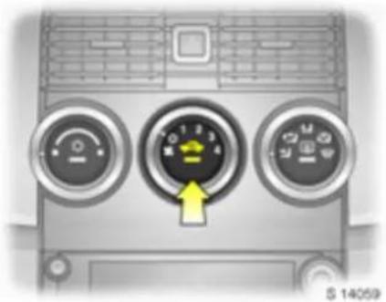
Air re-c irculat ion system
The air re-circulation button is used to set the ventilation system to re-circulation mode (control indicator illuminates in button).
If f u me s or un ple as a nt od ou rs pe ne tr at e the passenger compartment from outside, temporarily switch on air re-circulation system.
To increase the cooling power at high outside temperatures, temporarily switch on air re-circulation system.
108 Climate control
The air re-circulation system minimises the entry of outside air. The humidity increases, and the windows can mist up. The quality of the pass enge r compa rtm ent air deteriorates which may cause the vehicle occupants to feel drowsy.
Air distribution to 📂, 🌐 or 🌒: air re-circulation system is a automatically switched off, to speed up window demisting and avoid fogging. The control indicator in the button goes out.
If air distribution rotary switch is turned back to positions 2 or 3, the air recirculation system is switched back on and the control indicator illuminates in the button.

Convenience settings
■ Set cooling ⚙ as desired.
■ Air re-circulation system 📄 off.
■ Set air distribution rotary switch to ☑ or ☑.
■ Set temp erature rotary switch to desired position.
■ Switch on fan a t desired speed.
■ Open or align air vents as required.
Temperature rotary switch in centre of adjustment range: warmer air will flow into the foot well and cooler air into the upper zone, with warmer air coming from the side air vents and cooler air from the centre air vents.

Ma xim um cooling
Briefly open the window so that the heated air can dissipate quickly.
■ Cooling ⚙ on.
■ Activate air re-circulation system 📄
■ Set air distribution rotary switch to ↗.
■ Turn the temperature rotary switch anticlockwise as far as it will go (cold).
■ Set fan to 4.
■ Open side air vents.

Air intake
The air intakes in front of the windscreen in the engine compartment must be kept clear to allow air intake. Remove any lea ves, dirt or snow.
Note
If the windscreen mists up during damp weather, tem porarily set the system as described under "Demisting and defrosting the windows" - see page 106.
Cooling functions most efficiently when the wind ow s a re closed. If the p assenge r compartment has heated up considera bly after a long period in direct sunlight, briefly op en the wind ow s so that the hot air can escape quickly.
When cooling (air conditioning compressor) is switched on condensation forms, which is expelled from the underside of the vehicle.
At least one air vent must be open while cooling (air conditioning comp ressor) is on, in order to prevent the evaporator from icing up due to lack of air movement.
At low outside temperatures the cooling unit switches off automatically.
Maintenance
In order to ensure continuously efficient performance, the air conditioning compressor must be operated for a few minutes once a month, irrespective of the weather and time of year. Air conditioning compressor operation is not possible when outside temperatures are low.
In the event of a fault, consult a workshop.
Driving and operation
Driving hints 110
Saving fuel, protecting the environment . .... .... ....
Fuels, refuelling 114
Catalytic converter, exhaust gases... 116
Drive control system s .... 118
Brake system .... 122
ABS (AB) 124
Whee Is, tyres .... 125
Driv in g hints
The first 1000 km (600 miles)
Drive your vehicle at various speed s. Do not use full throttle. Never allow the engine to labour at low revs.
Make good use of all gears. Depress the accelerator pedal a ma ximum of around three quarters of the available p edal travel in 112 gears.
Do not drive faster than three quarters of maximum speed.
Do not b rake un n ec es sarily hard for the first 200 km (120 miles).
Never coast with engine not running Many units will not function in this situation (e.g. brake servo unit, power steering). Driving in this manner is a danger to your use if and others.
Brake servo unit
When the engine is not running, the brake servo unit is no longer effective once the brake peda I has been depressed once or twice. Braking effect is not reduced, but significantly greater force is required for braking.
Power steering
If the power steering fails or when being towed with the engine switched off, the vehicle can still be steered, but consid erably more force is required.
Driving in m ount ainous terrain
The cooling fan is electrically operated. Its cooling power is therefore independent of the engine speed.
Since a considerable amount of heat is generated at high engine speeds and less at lower speeds, do not shift down when climbing hills while the vehicle is still coping with the gradient in the higher gear.
Driving with a roof load
Not permitted.
Sw itching off the engine
When you switch off the engine, fans in the engine compartment may continue running for a while, to cool the engine.
If the engine temperature is very high, e.g. after driving in mountainous terrain, allow the engine to idle for ap prox. 2 minutes, in order to prevent heat accumulation.
V ehicles with turbocharged engine:
After running at high engine speeds or high engine loads, operate the engine briefly at a low load or run in neutral for approx. 30 seconds before switch in g off, in order to protect the turbocharger.
Save energy – more kilometres/miles
Please observe the running-in hints on the previous page and the tips for saving energy on the following pages.
Good, technically correct and economical driving ensures maximum durability and performance for your vehicle.
Overrun
The fuel supply is automatedally shut off during overrun, e.g. when the vehicle is being driven down long gradients or when braking. To enable the overrun cut-off to take effect, do not accelerate during overrun and do not declutch. To prevent damage to the catalytic converter, overrun cut-off is temporarily deactivated when the catalytic converter temperature is high.
V ehicles with turbocharged engine:
Flow -g enerate d noise s may be aud ible if the a celerator is released quickly, on account of air flow in the turbocharger.
Engine speed
Drive in a low engine speed range for each gear as much as possible.
Warming up
Run engine warm, do not warm up in idle. Do not a pply full throttle until the operating temperature has been reached.
Correct gear selection
Tra nsmission in neutral and without revving in the lower gears. Stop-and -g o traffic and driving at a speed too high for the selected gear increases wear and fuel consumption.
Change down!
When decreasing speed, shift down into the next lowest gear. Do not slip the clutch with a high-revving engine. This is especially important when hill climbing.
Clutch operation
Always depress the clutch pedal hard to the floor to prevent shifting difficulties and transmission damage.
When driving, do not use the pedal as a foot rest; this will ca use substantial clutch wear.
Cooling fan
The cooling fan is controlled via a therm oswitch and therefore only runs if necessary.
Pedals
Do not place any objects in the foot well which could slip under the pedals and inhibit the pedal travel.
To ensure the pedal travel is uninhibited, there must be no unrestrained mats in the area of the pedals.
Battery care
When driving slowly or when the vehicle is stationary, e.g. in slow urban traffic, stop-and-go traffic or traffic jams, turn off all unnecessary electrical loads where possible (e.g. heated rear window).
Saving fuel, protecting the environment
Trend-setting technology
When developing and manufacturing your vehicle, Opel used environment-friendly and prima rily recyclable materials. The production methods used to make your vehicle are likewise environmentally-compatible.
Recycling of production wastes keeps the circulation of material closed. Reduction of energy and water requirements also helps to conserve natural resources.
The a advanced design makes it easier to dismantle the vehicle at the end of its service life and separate materials for recycling.
Materia Is such as asbestos and cadmium are not used. The refrigerant in the air conditioning system is CFC-free.
New painting techniques employ water as a solvent.
End-of-li fe vehi cle rec overy
Information on end-of-life vehicle recovery centres and the recycling of end-of-life vehicles is available at www.opel.com.
Drive in an energy and environment-conscious way
■ High fuel consumption, noise levels and exhaust emissions are often caused by a driving style that is not energy and environment-conscious.
■ You should therefore drive with energy mind: "more kilometres/miles with less fuel".
Reduce the noise level and exhaust emissions by adopting an environment-conscious driving style. This is extremely worthwhile and im proves the quality of life.
Fuel consumption depends to a great extent on your own personal driving style. The following hints are intended to help you consume fuel at a rate that is as close as possible to the specified levels – see page 177.
Check your vehicle's fuel consumption every time you refuel. This facilitates early detection of any irregularities causing increased fuel consumption.
Warming up
■ Full throttle and warming up at idle speed increase wear, fuel consumption, exhaust emissions, the amount of pollutant in the exhaust and the amount of noise.
■ Driv e off as soon as possible after starting.
Uniform speed
■Hectic driving significantly increases fuel consumption, the exhaust emissions, the proportion of pollutant in the exhaust gases and the noise level.
■ Do not accelerate and brake unnecessarily. Drive at uniform speed.
Avoid frequent starting-off and stopping, e.g. at traffic lights, in short distance traffic and in queues of traffic, by means of clever planning. S elect roads with good traffic flow.
Idling
■ The engine also consumes fuel when idling.
If you have to wait for more than 1 minute, it is worthwhile switching off the engine. Five minutes of idling corresponds to ap prox. 1 kilometre (0.6 m iles) of driving.
Overrun
The fuel supply is automatically shut off during overrun, e.g. when the vehicle is being driven down long gradients or when braking – see page 111.
■ To enable the overrun cut-off to take effect and save fuel, during overrun do not ac celera te and do not declutch.
Correct gear selection
■ High revs increase engine wear and fuel consumption.
■ Do not race your engine. Avoid driving at high engine speeds.
Driving with an eye on the tachom ete r saves fuel. If possible, drive at low revs in each gear and a t a consta nt speed. Drive in top g ear as m uch a s possible, shift up as soon as possib le and do not shift down until the engine is no longer running truly.
High speed
■ The faster the speed, the higher the fuel consumption and the noise level. Driving at full throttle uses up a great deal of fuel and generates excessive noise and high emission levels.
■ Slightly relea sing the accelerator pedal results in distinct fuel savings with no major loss of speed.
Drive at no more than around three quarters of maximum speed and you will use up to 50% less fuel, without losing a great deal of time.
Tyre pressure
■ Inadequate tyre pressure, leading to higher road resistance, costs money in two ways: more fuel and increase sed tyre wear.
■ Regular checks (every 14 days) pay off.
Ele ctri cal loa ds
■ The power consumption of electrical equipment increases fuel consumption.
■ Sw itch off additional consumers (e.g. air conditioning, heated rear window) when they are no longer required.
Repair and maintenance
■ Improper repairs or adjustment and maintenance work can increase fuel consumption. Do not carry out work on the engine yourself.
You may infringe environmental laws out of ignorance by not disposing of materials properly.
Appropriate parts might not be recycled.
Contact with some of the materials involved may pose a health hazard.
■ We recommend that repair and maintenance be entrusted to your Opel Service Partner.
Extreme driving conditions
■ Driving up steep gradients, cornering, driving on poor roads and winter driving all increase fuel consumption.
Fuel consumption increa ses dramatically in urban traffic and at winter temperatures, especially on short trips when the engine operating temperature is not reached.
■ Follow the hints given above to keep consumption to a minimum under such conditions.
114 Driv in g and op era tio n
Fuels, refuelling
Fuel consumption
Fuel consumption is determined under specific driving conditions – see page 177.
Special equipment increases the weight the vehicle. As a result, they can increase fuel consumption and reduce the specified maximum speed.
For the first few thousand kilometres/miles, friction between the engine and transmission components is higher. This increases fuel consumption.
Fuel for petrol engines
Normal commercial high h-q quality fuels with a maximum ethanol content of 5% in accordance with DIN EN 228 are suitable (Catalytic converter - see page 116. Octane numbers - see page 175). The quality thereof has considerable effect performance, running and service life of the engine. The additives mixed with the fuel are extremely important. For this reason you must only refuse with high-quality fuels containing additives.
Fuels with ethanol content of greater than 5% do not comply with DIN EN 228 and must not be used unless the vehicle has been specifically developed and approved for these fuels.
Fuel with too low an octane number can cause pinking. Opel cannot be held liable for resulting damage.
Petrol with a higher octane number can always be used.
The ignition timing adjusts automatically to the grade of fuel used (octane number) – see page 175.
Use of petrol with an octane rating of 95 or higher will ensure economical driving.
Fuel filler cap
If replacing the fuel filler cap, be sure to use the original fuel filler cap for your model, to ensure full functionality.

Refuelling
⚠ Warning g
Care must be taken when handling fuel Before refuelling, switch off the engine and where applicab le any auxiliary heating with combustion chambers. Switch off mobile phones.
⚠ Warning
Fuel is flamm able and ex plosive. Avoid nak ed flam es or sparks when handling fuel or just in its vicinity. Do not smoke. This a Iso applies where fuel is perceptible only from its c harac teristic odour. If fuel od ours occur in the vehicle itself, ha ve the cause eliminated imm ediately by a workshop.

Fuel filler neck at left rear side of vehicle. Open the tank flap.
The fuel filler cap is locked and unlocked using the key provided. Turn key in lock cylinder clockwise to unlock k cap.
Unscrew the fuel filler cap by turning it anti-clock wise, and remove.
The fuel tank has a limiting system which prevents overfilling of the tank.
Correct filling depends to a large extent on proper operation of the fuel dispensing pump:
-
Fully insert the pump nozzle and switch it on.
-
At automatic switch off, the specified tank capacity is reached. Leave the filler nozzle in place until the flow stops.
Place fuel filler cap in position and turn it clockwise until tight and turn key in lock cylinder anti-clockwise to lock cap.
Close tank flap.
Wipe off any overflowing fuel immediately.
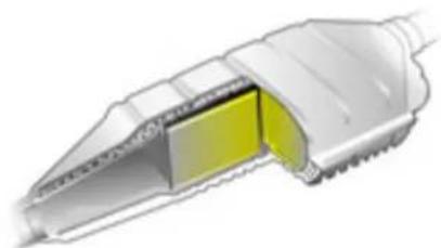
17199T
Catalytic converter, exhaust gases
Ca taly tic converter for petrol engines Leaded fuel will damage the catalytic converter and parts of the electronic system, thereby rendering them inoperative.
High quality fuels other than those listed on pages 114 and 175 (e.g. LRP 1) ) could damage the catalytic converter.
Damage to the catalytic converter or the vehicle may result if the following points are not observed:
■Consult a workshop as quickly as possible in the event of misfiring, irregular engine running following a cold start, a significant loss of engine power or other unusual malfunctions which may indicate a fault in the ignition system. If necessary, driving may be continued for a short time at a low speed and with a low engine speed.
Irregular engine running and lack of power when the Electronic Stability Program (ESP) kicks in are for operational reasons and can be ignored – see page 119.
■ If unburned fuel enters the catalytic converter, this may result in overheating and irreparable damage to the catalytic converter.
You should therefore avoid unnecessarily long use of the starter when starting-off, running the tank dry (an irregular fuel supply will lead to overhea ting) and starting the engine by pushing or towing.
If the emission control indicator flashes, slow down until the flashing stops and the control indicator is steady. Consult a workshop immediately. Emission control indicator – see page 117.

Controlling exhaust emissions
The combination of design measures mainly in the area of the fuel injection system and ignition systems, and the catalytic converter – has minimised the proportion of harmful substances in the e xhaust ga se s, such as carbo n monoxid e (CO), hydrocarbons (CH) and nitrous oxides (NQ).
Control indicator ☐ for exhaust
Illum inates when the ignition is switched on and during the start attempt. Goes out shortly after the engine starts running.
If it illuminates while the engine is running, there is a fault in the emission control system. The permitted emission values may be exceed d. Consult a work shop immediately.
Flashing with the engine running indicates a fault that may damage the catalytic converter. You can continue to drive without causing damage by slowing down until the flashing stops and the control indicator is steady. Consult a workshop immediately.
Exhaust gases
⚠ Warning
Engine exhaust gases contain poisonous carbon monoxide, which is colourless and odourless and could be fatal if inhaled. If exhaust gases penetrate the vehicle interior, open the windows and consult a workshop immediately.
During the first drive, smoke may develop because of wax and oil evaporating on the exhaust system. Park the vehicle in the open for a while a fter the first drive and avoid inhaling the fumes.
Maintenance
Have all maintenance work carried out
at the intervals specified by Opel. We recommend that you entrust this work to your Opel Service Partner, who has proper equipment and trained personnel availab le. Elec tronic testing systems permit rapid dia gnosis and remedy of faults. This way you can be certain that all components of the vehicle's electrical, injection and ignition systems operate correctly, that your vehicle has a low level of pollutant emission and that the catalytic converter system will have a long service life.
You are thereby making an important contribution towards keeping the air clean and compliance with emissions legislation.
The Service work includes testing and adjusting the fuel injection system and ignition system. For this reason, have all Service work carried out at the intervals specified by Ope I (see chapter "Serv ic e, Maintenance" on page 165).
Drive control systems
Electronic Stability Program (ESP), Electronic Stability Control (E SC)
Electronic Stability Control (ESC) is a component part of the Electronic Stability Program (ESP).
ESP im proves driving stability when necessary in any driving situation, regardless of the type of road surface or tyre grip. It also prevents the drive wheels from spinning.
The system monitors vehicle movements. As soon as the vehicle starts to swerve (understeers/oversteers) engine output is reduced (the sound of the engine changes) and individual wheels are specifically braked. This considerably improves the driving stability of the vehicle on snow and ice and on wet or slippery road surfaces.
ESP is ready for operation as soon as the ignition is switched on and control indicator goes out.
The ESP control process is disp la yed by the flashing of ⚙.
The vehicle is now in a critical situation; ESP allows you to keep control of the vehicle and reminds you to match your speed to the road conditions.
Warning
Do not let this special safety feature tempt you into taking risk when driving
Traffic safety can only be achieved by adopting a responsible driving style.

Control indica tor
Illuminates for a few seconds when the ignition is switched on. The system is ready for operation when the control indicator goes out.
Flashing during driving:
This shows the system has come into action. The engine output may be reduced (the sound of the engine changes) and the vehicle may be braked automatically to a small degree.
The d riv er information centre also shows "ESC ACTIVE" and/or "LO W TR AC TION" when the system has come into action. See page 69.
"ESC" appears in some warning messages. ESC is a component part of the Electronic Stability Program (ESP), improving driving stability.
Illum inates while driving:
The system is switched off or a fault is present. Continued driving is possible. The driving stability can however deteriorate depending on road surface conditions.
The driver information centre shows "ES C OFF", "SE RVICE ES C" or "SERVICE TR AC TION" if a sy stem fault occurs. See pages 69, 70.
The driver information centre shows "TRACTION O FF" and/or "ESC OFF" if the system has been switched off. See pages 69, 70.
Reactivate ESP or have the cause of the fault remedied by a workshop. The system's integrated self-diagnostics allow faults to be quickly remedied.
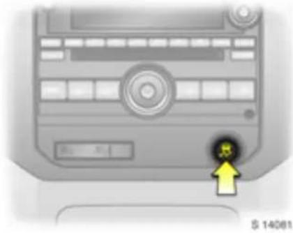
Switching off:
The traction control aspect of ESP can be switched off by pressing button ☒ once.
ESP can also be switched off altogether by pressing and holding the button for more than 10 seconds.
When traction control and/or ESP have been deactivated, control indicator illuminates in the instrument panel.
The driver information centre shows
"TRACTION OFF" if the button is pressed once, and also "ESC OFF" if the system has been switched off a ltogether. See pages 69, 70.
Traction control and ESP are switched on aga in by pressing button 2 again (control indicator goes out immediately) or the next time the ignition is switched on.
⚠ Warning
When the traction control aspect of ESP is switched off, it is possible to lose traction.
Do not attempt to shift gears while the rear wheels are spinning, to prevent damage to the transmission. Failure to follow these instructions can cause injuries or put lives at risk.

Competitive mode allows the driver to have full control of the rear wheels while ESP continues to assist in maintaining the driving stability of the vehicle by braking the front wheels as necessary.
To activ ate:
Press button twice within 5 seconds.
Control indica tor ⚙ illuminates in the instrument panel. The traction control aspect of ESP is deactivated for high performance driving.
The driver informa tion centre shows "C OMPETI TI VE MODE". Se e pa ge 69.
Ad just your driving a cording ly.
To deactivate:
Briefly press button 📋 again or switch off the ignition.
Warning
When competitive mode is engaged, it is possible to lose traction.
Do not attempt to shift while the rear wheels are spinning, to prevent damage to the transmission. Failure to follow these instructions can cause injuries put lives at risk.
pr
Cruise control
The cruise control can store and maintain speeds above approx. 30 km/h (20 mph). Deviations from the stored speed may occur when driving uphill or down hill.
For safe ty re ason s, cruise con trol cannot be activated until the brak e pedal has been ope rated once.
Cruise control is operated with buttons ☑, + RES, and - SET on the left side of the steering wheel.
Do not use cruise control if it is not advisable to maintain a constant speed (e.g. in situations presenting a danger to yourself and other road users, in heavy traffic or on winding, slippery or greasy roads).
When cruise control is a active, reaction times may be increased due to the different position of the feet.
⚠ Warning
The driver is always responsible for maintaining an appropriate speed if cruise control is on. Failure to follow instructions can cause injuries or p at risk.
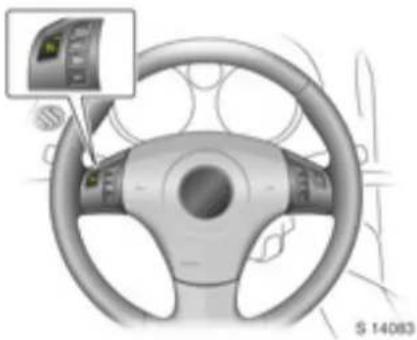
To activate:
Press button Ⓧ to turn cruise control on. The control indica tor in the button will illuminate.
lives
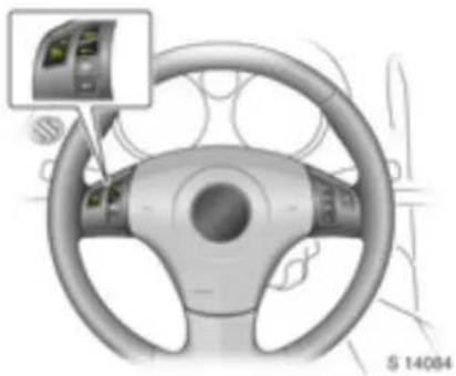
Accelerate to the desired speed, press the - SET button and release it: the current speed is stored and maintained.
The accelerator pedal can be released after setting cruise control speed.
Vehicle speed can be increased temporarily for overtaking purposes, by depressing the accelerator pedal. When the accelerator pedal is released, the previously stored speed is resumed.
"CRUISE ENGAGED" appears in the driver information centre with cruise control active.
Check control warning messages - see page 68.
Increase speed:
With cruise control activ e, hold do wn button + RES or briefly press it repeatedly: speed is increased continuously or in steps of 1.6 km/h (1 m ph) without using the accelerator pedal.
When button + RES is released, the current speed is stored and maintained.
Alternatively, use the accelerator pedal to increase vehicle speed, press button - SET and release it, then release the accelerator pedal.
When button - SET and the accelerator pedal are released, the current speed is stored and maintained.
Decrease speed:
With cruise control act iv e, ho ld down button - SET or briefly press it repeatedly: speed is reduced continuously or in steps of 1.6 km/h (1 mph).
When button - SET is released, the current speed is stored and maintained.
To dea ctiv ate:
Switch off cruise control when not needed, to avoid accidental activation.
Press button ☑: cruise control is switched off, the control indicator in the button goes out and the vehicle slowly decelerates. To continue driving, depress the accelerator pedal in the usual manner.
For reasons of safety, cruise control deactivates under certain driving conditions. For example:
■ if the vehicle's speed drops below approx. 30 km/h (20 mph) or
■ if the brake peda I is depressed or
■ if the clutch p edal is depressed or
■ if the Electronic Stability Program (ESP) comes into a ction, to improve driving stability and limit wheel spin.
Deactivating cruise control does not switch off the system.
Resuming the stored speed:
Briefly press button + RES at a speed above 30 km/h (20 mph): speed selected before cruise control was deactivated is resumed.
The value of the stored speed is deleted when cruise control has been switched off by pressing button ☑, and when the ignition is turned off.
Brake system
The effectiveness of the brakes is an important factor for traffic safety.
To improve effectiveness, do not brake unnecessarily hard for the first 200 km (120 miles) after new brake pads have been fitted.
Brake pad wear must not exceed a specified limit. Regular ma intena nce as detailed in the chapter "Service, Maintenance" on page 165 is therefore of the utm ost importance for traffic safety.
Have worn b ra ke pads replaced by a workshop. Pads which have been tested and a approved ensure optimum b ra ke performa nc e.
Brake pads that have worn to their minimum thickness generate a grinding noise. Continued driving is possible. Have the brake pads replaced as soon as possible by a workshop.
⚠ Warning
Disregard of these instructions may lead to injuries or endanger lives.
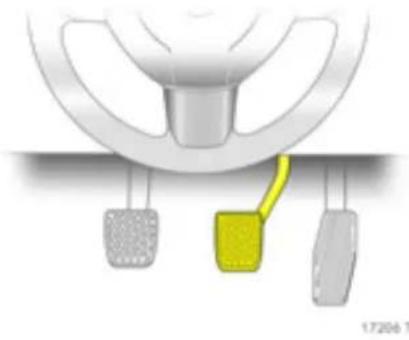
Brak e assist
Powerful application of the brake peda I automatically applies max imum braking force a amplification to a chieve the shortest possible braking distance under full braking (brake a ssist).
Maintain s teady press ure on the brake pedal for as long as full-on braking is to continue. When the brake pedal is released, the maximum brake force amp lification is taken away.
Foot brake
The foot brake comprises two independent brake circuits.
If a brake circuit fails, the vehicle can still be braked using the other brake circuit. If this occurs, however, the brake pedal must be depressed quite far using considerable force before braking effect occurs. The distance required for braking will be greater. Consult a workshop before continuing your journey.
To ensure the full pedal travel can be utilized, especially in case of a fault in one of the brake circuits, there must be no unrestrained mats in the vicinity of the pedals – see page 111.
When the engine is not running, the assistance of the brake servo unit ends once the brake peda I has b een depressed once or twice. Braking effect is not reduced, but braking requires significantly greater force.
Check the brake lamps before starting out on a journey.
Just before starting any journey, check effectiveness of brake system at low speeds and without obstructing moving traffic, particularly if brakes are wet, e.g. after washing the vehicle.
The brake/clutch fluid level should be checked regularly. If the brake/clutch fluid level is too low and the hand brake is not applied, control indicator ① illuminates in the instrument panel – see page 56.
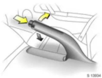
Hand brake
Always apply hand brake firmly. On slopes, apply the hand brake as firmly as possible.
The mechanical hand b ra ke a ffects the rear wheel brakes. They automatically engage when the lever is pulled.
To release the hand brake, lift handle slightly, press release button and lower handle all the way down.
To reduce the operating forces of the hand brake, depress the foot brake at the same time.

Control indicator Ⓐ for brake system Illum inates when the ignition is switched on if the hand brake is applied or if the br clutch fluid level is too low.
Flashes at speeds over 8 km/h (5 m ph) if hand brake is applied. Release hand brake before continuing journey, to avoid overheating and damaging the brake system. See also page 70.
Brake and clutch fluid – see page 156.
⚠ Warning
If the control indicator illuminates when the hand brake is not ap plied: Stop. Interrupt your journey immediately. Consult a workshop.
ABS (ABS)
The AB S (Anti-lock Brake System) continuously monitors the brake system and p reveals the whee is from locking, independently of the type of road surface and the tyre grip.
It starts to regulate the braking pressure as soon as a wheel shows a tendency to lock. The vehicle remains stee rable, even in the event of very heavy braking, for instance on bends or when swerving to avoid an obstacle. Even in the case of full-on braking, the ABS makes it possible to drive round an obstacle without releasing the brakes.
ABS control is made apparent through a pulse in the brake pedal and the noise of the regulation process.
Warning
For optimum braking, keep the brake peda I fully depressed throughout the braking process, despite the fact that the pedal is pulsa ting. Do not reduce the pressure on the pedal.
Do not let this special safety feature tempt you into taking risk when driving
Traffic safety can only be achieved by adopting a responsible driving style.

Control indica tor (ns) for ABS
Illuminates for a few seconds after the ignition is switched on. The system is ready for operation when the control indicator goes out.
If the control indicator does not go out after a few seconds, or if it illuminates while driving, there is a fault in the ABS. The brake system remains operational without ABS regulation.
Self-check
Each time the ignition is switched on and the engine is started, after setting off at a speed of about 3 km/h (2 mph), the system performs a self-check which may be audible.
Fault
Warning
If there is a fault in ABS, the wheels may be subject to locking due to braking that is heavier than normal. This may cause the vehicle to sw erve. The adva ntag es of ABS are no longer op erational.
You can continue driving, provided you drive with care and anticipation.
Have the cause of the fault remedied by a workshop. The system's integrated self-d ia gnostics allows faults to be quickly remedied.
Wheels, tyres
See page 179 for suitable tyres and restrictions.
Factory-fitted tyres are matched to the chassis and offer optimum driving comfort and safety.
Changing tyre/wheel type
Before changing to tyres or wheels of a different size, seek advice as regards technical possibilities. Seek the assistance of a workshop.
If tyres of a different size than those fitted at the factory are used, the electronic speedometer may require reprogramming to ensure that the correct speed is displayed.
⚠ Warning
Use of unsuitable tyres or wheels may lead to accidents and render the vehicle unroadworthy.
Fitting new tyres
Please fit tyres in pairs. Sets would be even better. Replace tyres with:
■ the same size,
■ the same design,
■ the same make,
■ the same tread pattern on one axle.
Fit directional tyres such that they roll in the direction of travel. The rolling direction is indicated by a symbol (e.g. an arrow) on the sidewall.
Tyres fitted opposing the rolling direction (e.g. when a tyre is changed) should be refitted as soon as possible. This is the only way to obtain full benefit from the design properties of the tyre.
Observe legal requirements w hen disposing of tyres.
Some brands of tyres have a b eaded edge for alloy wheels to protect against damage. If a wheel trim is used on steel wheels with beaded-edge tyres, the following procedure must be followed:
■ Wheel trims and tyres that are a proved for the respective vehicle and c om ply with all of the relevant wheel and tyre combination requirements must b e used.
■ If the wheel trims and tyres used are not approved, the tyres must not have a beaded edge.
⚠ Warning
Use of unsuitable tyres or wheel trim s could lead to sudden pressure loss and thereby accidents.
Tyre pressure
Check tyre pressu re s w hen cold, a t least every 14 days and prior to any long journey.

§ 14735
Tyre pressures – see page 180 and the tyre and loading information label on the B-pillar, visible with the driver's door open. Have tyre and loading information label replaced after changing to a different tyre size.
Do not reduce tyre pressure when the tyres are warm. Otherwise the pressure may drop below the permissible minimum when the tyres cool down.

After having checked the tyre pressures, tighten the valve caps.
Incorrect tyre pressures will impair safety, vehicle handling, comfort and fuel economy and will increase tyre wear.
If the pressure is too low, this can result in considerable tyre warm-up and internal damage, leading to tread separation and even to tyre blow-out at high speeds.
Hidden tyre damage is not eliminated by adjusting ty re p reassure.
⚠ Warning
Incorrect tyre pressure can lead to tyre rupture.

Tyre condition, wheel condition
Drive over edges slowly and at right angles if possible. Driving over sharp edges can cause concealed da mage to tyres and wheels that only becomes noticeable later.
Do not trap tyres when parking.
Check tyres regularly for damage (foreign bodies, punctures, cuts, crack s, bulg es in sidewalls). Check wheels for damage. In the event of damage or abnormal wear, consult a workshop.
⚠ Warning
Dama ge may lead to tyre blow-out.
![graph TD A["Node 1"] --> B["Node 2"] B --> C["Node 3"] C --> D["Node 4"] D --> A style A fill:#f9f,stroke:#333 style B fill:#f9f,stroke:#333 style C fill:#f9f,stroke:#333 style D fill:#f9f,stroke:#333](/content/2026/06/1312191/images/2feb641a9f1dc0fbf7a4cb46495f540f3df4f8c8c22cd4f811a7656d738757c2.jpg)
Tread depth
Check tread depth at regular intervals.
If there is more wear at the front than the rear, swap round front wheels and rear wheels.
Correct the tyre pressure.
Tyres should be replaced for safety reasons if tread depth drops b elow 2-3 mm (4 mm for winter tyres).
128 Driv in g and op era tio n

The legally permissible minimum tread depth (1.6 m m) has been reached when the tread has worn down as far as one of the wear indicators (TWI 1 ). A number of wear indicators a re spaced at equal intervals around the tyre within the tread. Their position is indicated by markings on the tyre sidewall.
General information
■ The danger of aq uap laning is greater if the tyres are worn.
■ Tyres age, even if they are used only very little or not at all.
■ Never fit used tyres the previous history and use of which you do not know.
■ So as not to im pair brake cooling, use only wheel trims app roved for use on your vehicle.
Tyre designations
Meaning s:
e.g. 24 5/45 R 18 1 00 W
245 = T y r e w i d t h i
45 = Aspect ratio
(tyre height to tyre width) in %
R = Belt type: Radial
18 = Rim diameter in inches
100 = Load index
e.g.: 100 corresponds to 800 kg
Q Up to 160 km/h (100 mph)
S Up to 180 km/h (112 mph)
T Up to 190 km/h (118 mph)
H Up to 210 km/h (130 mph)
V Up to 240 km/h (150 mph)
W Up to 270 km/h (168 mph)
Winter tyres *
For notes on fitting new tyres – see page 126.
See page 179 for restrictions.
W inter r tyre s im prove saf e ty at tem peratures be low 7 °C and should therefore be fitted on all the wheels.
The design of summer tyres means they have limited qualities for winter driving.
If the maximum permissible speed for the winter tyres is less than that of the vehicle, a notice indicating the maximum permissible speed for the tyres must be affixed within the driver's field of vision 1) .
Wheel trims
If the wheel trims and tyres used are not approved, make sure that the tyres do not have a beaded edge – see page 126.
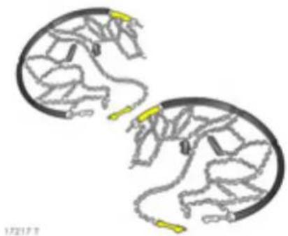
Tyre chains *
Restrictions and further information - see page 179.
Tyre c hains are only perm itted on the driven wheels (rear axle). They must be fitted to the tyres symmetrically in order to achieve a concentric fit.
Always use fine-linked chains that add no more than 11 mm to the tyre tread and the inboard sides (including chain lock).
Wheel trim on steel wheels could come into contact with parts of the chain and be damaged. Remove the wheel trim.
Tyre cha ins may only be used at speeds up to 50 km/h (30 mph) or up to the tyre chain ma nufacturer's recommended maximum speed, whichever is lower.
When travelling on roads that are free of snow, they may be used for brief periods only since they are subject to rapid wear on a hard road and may snap.
Avoid sharp turns, bumps and holes and do not lock the wheels when braking, to avoid damaging the tyre chains.
Re-tighten the chains after d riving for app rox. 1 km (0.6 miles). If, at any time you hear or suspect that the chains are contacting the vehicle, stop and re-tighten the chains.
Always read the instructions supplied with the tyre chains.
Correct the tyre pressure b before starting-off. See page 180.
Self-help, vehicle care
Bonnet release .... 130
Starting the engine with 132 jump leads * ....
First-aid kit ⊕ *, warning triangle △ *.... 135
Electrical system ..... 141
Inspection system .... 151
Opel genuine parts and accessories. 152
A note on safety ..... 152
Checking and topping up fluids ..... 152
Wind screen wipe rs.... 157
Wind screen washer system .... 158
Protection of electronic components 159
Vehicle decomm issioning. ..... 160
Vehicle re commissioning.....160
Vehicle care....161
⚠ Warning
Disregard of these instructions may lead to injuries or endanger life. Vehicle passing should be informed accordingly.
131
134
135
159
\$1

Bonnet release
To open the bonnet, pull the release lever located on the driver's side below the instrument panel.
The bonnet will then be unlatched and will open partially. R return release lever to its original position.
Do not pull release lever while the vehicle is moving.

To open completely, lift bonnet upwards from the edge nearest the windscreen. Air pressurised support rods will hold the bonnet open.
When the bonnet is opened, leaves, dirt or snow can obstruct the air intake. Remove any leaves, dirt or snow. Air intake – see page 109.
Never drive with bonnet open.
To close bonnet, lower it gradually before pushing it firmly into its catch.
Check that the bonnet is latched in position before driving, by pulling a t its rear edge. If it is not engaged, repeat closing procedure.
⚠ Warning
To avoid causing da mage to the doors and the bonnet, ensure the driver's door and the passenger's door are both closed correctly before closing the bonnet.
Starting
Do not start with h quick charger
This prevents damage to electronic components.
Warning
If the vehicle battery requires charging while still in the vehicle, ensure there is adequate ventilation in and around the battery compartment to prevent risk of explosion.
Do not start by pushing or towing
Because your vehicle is fitted with a catalytic converter, it must not be started by pushing or towing – see page 116.
The vehicle can only be started using jump leads – see following page.
132 Self-help, vehicle care
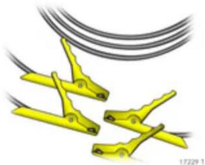
Starting the engine with jump leads *
A vehicle with a discharged battery can be started using jum p leads, the ba ttery of another vehicle and your vehicle's jum p start terminals - see page 133. Attempts to start the vehicle should be made at intervals of 1 minute and should not last longer than 15 seconds.
⚠ Warning
This must be done with extreme care. Any deviation from the following instructions could lead to personal injury or damage resulting from battery explosion, as well as to damage to the electrical systems in both vehicles.
■ Never expose the battery to naked flames or spark s.
■ A discharged battery can freeze at temperatures of 0 °C. Defrost the frozen battery in a warm room before connecting jump leads.
■ Do not allow battery fluid to come into contact with eyes, skin, fabrics or painted surfaces. The fluid contains pulp huric acid which can cause injuries and damage in the event of direct contact.
■ Wear eye protection and protective clothing when handling a battery.
■ Use auxiliary battery with same voltage (12 volts). Its capacity (Ah) must not be considerably less than that of the discharged battery. Voltage and capacity information can be found on the batteries.
■ Use jump leads with insulated terminals and a cross section of at least 16 mm 2 .
■ Do not disconnect the discharged battery from the vehicle.
■ Switch off all unnecessary electrical consumers.
■ Do not lean over the battery during jump starting.
■ Do not allow the terminals of one lead to touch those of the other lead.
■ The vehicle should not touch while jumping starting g.
■ Apply hand b ra ke. Transmission in neutral.
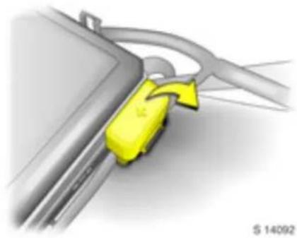
Jum p start terminals
In the event of a discharged battery, the jump start terminals located in the engine compartment enable the vehicle to be started without the need to access the battery.
The p positive jum p start terminal is identified by a “+” sign on the red insulating cover, located next to the engine compartment fuse box.
Open the red insulating cover to access the positive "+" terminal connector. Ensure the red insulating cover is latched back into position when not in use.

The nega five jump start terminal is identified by a "GND (-)" sign on a ground bracket, located below the engine beauty cover.

Connect the leads in the order shown in the illustration:
- Connect one end of the first jump lead to the positive terminal 1 of the battery providing the jump start (identified by "+" sign on batte ry case or terminal).
- Connect the other end of this lead to the positive jump start terminal 2 of the vehicle with the discharged battery ("+" sign).
- Connect the first end of the other jump lead to the negative terminal 3 of the battery providing the jump start ("-" sign).
- Connect the other end of the second jum p lea d 4 to the negative jum p start terminal ground bracket, identified by "GND (-)".
134 Self-help, vehicle care
■ Do not connect leads to negative terminal of discharged battery!
■ Route the leads so that they cannot catch on rotating parts in the engine compartment.
■ Start the engine of the vehicle providing the jump start.
■ After 5 minutes, start the other engine. Start attem pts should be made for no longer than 15 seconds at an interval of 1 minute.
■ After the start, allow both engines to idle for 3 minutes with the leads connected.
In order to avoid excess voltage in the electrical system, be fore moving a lead, switch on an electrical consumer (e.g. lamps, heater window) in the vehicle receiving the jump start.
■ Reverse above sequence exactly when removing leads.
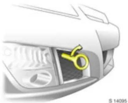
Towing
Towing the vehicle
Screw the front towing eye (stowed in a bag in the lugga ge compartment) fully into the front towing point.
Attach a tow rope * - or better still, a tow rod * - to the towing eye, never to the bumper or front suspension units.
⚠ Warning
Never lift the vehicle using the towing eye!
Place the gear shift lever in neutral. Switch on the ignition to release the steering column lock and to permit operation of the brake lamps, horn and windscreen wipers.
Drive off slowly and avoid jerky movements. Imperm issible trac tive forces could da mage the vehicles.
⚠ Warning
More brake pedal pressure is necessary when b ra king since the brake servo unit is operative only when the engine is running.
Considerably greater steering force is necessary since the power steering unit is operative only when the engine is running.
To prevent the entry of exhaust gases from the towing vehicle, switch on the air recirculation system and close the windows.
Seek the assistance of a workshop.
Towing service
Entrust your vehicle only to the towing service of your choice and obtain an estimate on towing costs before employing any towing service. In this way you avoid unnecessary costs and possible insurance problems during claim processing.
First-aid kit ⊕ * , warning triangle △ *
Your first-aid kit and warning triangle can be accommodated in the luggage compartment.
Vehicle tools
The front towing eye should be kept in the bag provided when not in use and stowed in the luggage compartment.
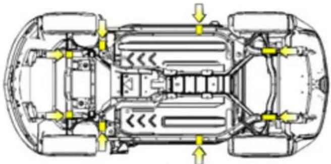
S 14173
Puncture
In order to minimise vehicle weight, your vehicle is not fitted with a jack or a spare wheel.
It is recommended that wheel changing and jacking of the vehicle are only carried out by a workshop.
However, if the vehicle needs to be lifted in an emergency, suitable jacking points are located on the vehicle underbody.
Warning
When raising the vehicle on a workshop hoist, proper lift pads must be used to avoid causing damage to the vehicle. Contact a work shop.
136 Self-help, vehicle care
Tyre repair kit
Minor damage to the tyre tread, e.g. from foreign bodies, can be tem porarily repaired using the tyre repair kit.
Do not remove foreign bodies from the tyres. Damaged areas bigger than 4 m m and da mage at the tyre rim cannot be repaired using the tyre repair kit.
⚠ Warning
Driving with tyre pressure that is too low can cause invisible damage to the tyres. This dama ge c cannot be remedied using the tyre repair kit. Park vehicle and contact a workshop.
The tyre repair kit can be used to seal small punctures with a liquid sealant. Use of the sealant does not constitute a permanent rep air but is designed as an emergency measure, to allow the vehicle to be drive while awaiting tyre replacement.
The tyre repair kit can also be used to infla te the tyres to the c orrect tyre pressure (see page 180) without using the sea lant.

For important information – see page 140. If you have a flat tyre:
■ Park on a level, firm and non-slippery surface.
■ Sw itch on hazard warning lamps, apply hand brake, engage reverse gear and switch off engine.
- Correctly set up the warning triangle . Warning triangle - see page 135.
Never use the liquid sealant on more than one tyre at a time.
The tyre repair kit is located in a stowage compartment on the driver's side at the rear of the lugg age compartment.
Remove the strap from the tyre repair kit by pressing the tabs on either side of the buckle and remove the tyre repair kit from its foam container.

- Place the tyre repair k it on level ground and unwrap the sealant filling hose from the compressor unit.
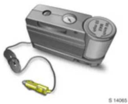
- Remove ac cessory plug from the unit by pulling out the top part of the wrapped cord first, followed by the bottom part. Disconnect the ac cessory plug.
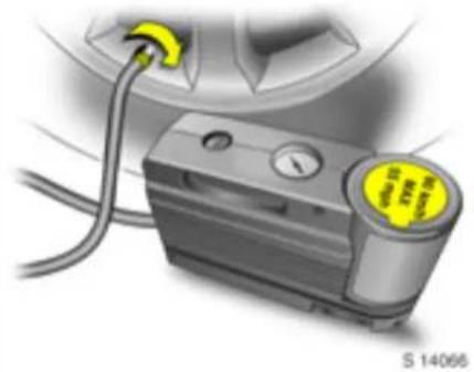
-
Unscrew dust cap from defective tyre and screw sealant filling hose to valve.
-
Ensure the compressor on/off switch h is in position O (off).

-
Open cover of accessory socket and insert accessory plug of tyre repair kit.
-
Start the engine (see page 17). The engine must be running while using the air compressor.
138 Self-help, vehicle care

-
Switch compressor on/off switch to position I (on).
-
All of the sealant is pumped into the tyre and the tyre is inflated.
Sea lant may leak from the puncture hole until the vehicle has been driven and the hole sealed.
Do not run the compressor for more than 10 minutes, see "Important information" on page 140.

-
Check the compressor pressure gauge. If there is no reading, the sealant filling hose to valve connection may be faulty. Re-check the connection.
-
Inflate the tyre to the correct pressure - see page 180.
As the pressure gauge reading is slightly high while the compressor is on, switch compressor off to gain an accurate pressure reading.
If the p rescribed tyre pressure is not obta ined within 10 minutes, the tyre is too badly damaged. Switch off engine and compressor, remove accessory plug and unscrew seala nt filling hose before contac ting a workshop.
-
When the correct tyre pressure has been reached, switch compressor on/off switch to position O (off).
-
Switch engine off and unplug the accessory plug from the accessory socket.
-
Disconnect sealant filling hose from tyre valve and replace the dust ca p.
Exercise caution when removing tyre repair kit components, as they may still be hot after use.
Wrap sea lant filling hose around compressor unit in its original location. Stow accessory plug in compressor unit by wrapping the cord, reconnecting the ac cessory plug, then pushing in the bottom part of the wrapped cord followed by the top part into the compressor unit.
Pe el off the sticke r containing the maximum permitted speed that is affixed to the sealant bottle, and attach it within the driver's field of view. For sticker – see page 137, Fig. S14066.
- Place the tyre repair kit in its foam container and wrap the strap a round it. Snap the buckle into place and tighten the strap as necessary.
- Remove any excess sealant using a cloth. S tow tyre repair kit in lugga ge compartment in its original location.
- Collap se warning triangle * and stow in luggage compartment – see page 135.

§ 14075
- Continue driving imm ediately so that sealant is evenly distributed throughout the tyre.
After driving ap prox. 10 km (6 miles) (but no more than 10 min ut e s), stop and check tyre pressure, using the compressor:
Unlock air compressor hose from underside of compressor unit by pulling the lever up (see illustration). Detach the hose from the sealant bottle and pull out the hose.
Push a ir compressor hose directly on to tyre valve and push lever down to secure in place.
- Check the compressor pressure gauge. As long as the tyre pressure has not dropped more than 0.7 bar below the correct tyre pressure, it may be adjusted to the prescribed value. Repeat the procedure until there is no more loss of pressure.
If the tyre pressure has dropped more than 0.7 b ar below the correct tyre pressure, the vehicle must not be driven. Contact a work shop.
- Stow tyre repair kit in luggage compartment.
Important The driving characteristics of the repaired
⚠ Warning
Do not drive faster than 90 km/h (55 mph).
Have the repaired tyre replaced as soon as possible.
Do not d rive with more than one temporarily repaired tyre.
Steering and handling may be affected. Take bends slowly.
Only stow the tyre repair kit in the lugga ge c om partment.
tyre is severely affected, therefore have this tyre rep laced without delay by a w orkshop.
If unusual noise is heard or the compressor becomes hot, turn c ompressor off for at least 30 m inutes.
The built-in safety valve opens at a pressure of 7 bar.
Protect compressor from moisture and rain.
Pay attention to storage information and best before date on sea lant bottle. It is sealing capability is not guaranteed after this time.
The sealant bottle can only be used once. Replace used sealant bottle.
The compressor and sealant can be used from app rox. -30 °C.
Dispose of used tyre repair kits in accordance with the applicable laws.
Consumers must not be connected to the accessory socket at the same time when the tyre repair kit is being used.
Electrical system
⚠ Warning
Electronic ignition systems use a very high voltage. Do not touch the ignition system; danger to life.
Fuses The vehicle has two fuse boxes: one behind a cover on the right-hand side of the passenger com partment and another in the engine com partment.
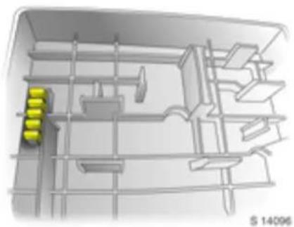
It is advisable to carry a complete set of fuses in the vehicle.
Store spare fuse s on the underside of the engine c om partment fuse box cover. Opening the cover - see page 144.
Before replacing a fuse, turn off the respective switch and the ignition.

A blown fuse can be recognised by its melted wire. Do not install a new fuse until the cause of the fault has been remedied.
Different types of fuse are used.
| Fuse Fuse colour rating | |
| Grey 2 ABrownish yellow 5 ARed 10 ABlue 15 AYellow 20 ATransparent Orange | 25 A40 A |
142 Self-help, vehicle care

172601
| Fuse Fuse colour rating | |
| Blue 20 APink 30 AGreen 40 ARed 50 AYellow 60 A |


18669 T
Place the fuse extractor on the various types of fuse from the top or side, and withdraw fuse.
Only install fuses of the specified rating. Each fuse has its rating written on it, in addition the fuses are colour coded.
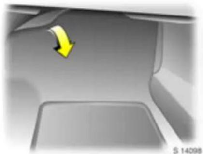
Fuses and the most important circuits they protect
Fuse box in passenger compartment The fuse box is located at the end of the passenger's foot well, below the instrument panel.
Pull floor carpet from the top to access fuse box cover.
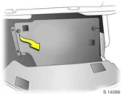
To open, pull cover from the left-hand side to detach from Velcro pads and remove cover.
Do not store any objects behind the cover.
Spare fuses, fuse extractor - see pages 141, 142.
Some functions are protected by several fuse s.
No. Circui t Rating
1 -
2 -
3 -
4 -
5 Amplifier 20 A
6 Instrument panel cluster 10 A
7 Ignition switch, 2 A electronic im mobiliser
8 Brake lamp 10 A
9 Climate control, 10 A electronic im mobiliser
10 -
11 Spare 20 A
12 Airb ags 10 A
13 Spare 10 A
14 Winds cree n wipe rs 10 A
144 Self-help, vehicle care

\$ 14122
No. Circuit Rating
15 Climate control, 10 A
seat occupancy recognition,
clutch switch,
crank relay,
instrument panel cluster
16 Elec tric wind ow s 30 A
17 -
18 -
19 Stee ring whee I controls 2 A
20 Spare 15 A
21 Spare 20 A
No. Circuit Rating
22 -
23 Radio 15 A
24 Sensing and Diagnostic Module 10 A
25 Engine Control Module, 10 A Transm ission Control Module
26 Door locks 15 A
27 Interior lam ps 10 A
28 Steering wheel control 2A illumination

Fuse box in engine comp artm ent
⚠ Warning
Turn off engine before opening engine compartment fuse box; risk of injury – see page 152.
To open the cover, press locking tabs at each end of the fuse box inwards. Lift the cover upwards to remove.
Do not store any objects behind the cover.
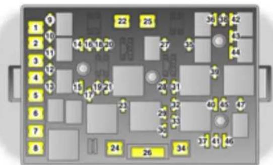
S.14126
Some functions are protected by several fuses.
No. Circuit Rating
1 -
2 Bod y Control Module 50 A
3 Bod y Control Module 240 A
4 Crank 30 A
5 Bod y Control Module 3 30 A
6 -
7 Heated rear window 20 A
8 Cooling fan 60 A
No. Circuit Rating
9 Fuel pump 15 A
10 -
11 Luggage compartment 5 A
12 Luggage compartment 25 A
13 -
14 Electric exterior mirrors 5 A
15 Sp are 10 A
16 -
No. Circuit Rating
| 17 | Air conditioning | 10 A |
| 18 | Data link connector | 15 A |
| 19 | Spare 20 A | |
| 20 | - | |
| 21 | Outlet | 20 A |
| 22 | - | |
| 23 | Emissions | 10 A |
| 24 | Vacuum pump | 20 A |
| 25 | - | |
| 26 | Electric seat | 20 A |
| 27 | - | |
| 28 | Engine Control Module, tra nsmission | 15 A |
| 29 | Engine Control Module | 20 A |
| 30 | Turbo, Cam phaser | 10 A |
| 31 | - | |
| 32 | Reversing la mp | 10 A |
| 33 | Ignition coils | 15 A |
| 34 | ABS | 10 A |
| 35 | Fog lamps | 15 A |
No. Circuit Rating
| 36 | Horn 15 A | |
| 37 | Remote central locking 10 A | |
| 38 | Driver's side high beam 10 A | |
| 39 | Windscreen wipers | 25 A |
| 40 | ABS | 10 A |
| 41 | ABS | 20 A |
| 42 | Passenger's side high beam | 10 A |
| 43 | Passenger's side low beam | 10 A |
| 44 | Driver's side low beam | 10 A |
| 45 | Instrument panel ignition | 20 A |
| 46 | Canister vent | 10 A |
| 47 | Park in g lamps | 15 A |
Bulb replacement
| Warning |
| To avoid causing da mage to the doors and the bonnet, ensure the driver's o and the passenger's door are both closed correctly before closing the bonnet. |
Halogen bulbs contain pressurised gas. Take special care when d isposing of halogen bulbs. Never touch the glass with bare fingers; risk of injury.
Before replacing a bulb, switch ignition off and turn off relevant light switch.
Only hold new bulb at base! Do not touch the bulb glass with bare hands, otherwise fingerprints on the glass evaporate. Residue builds up on the reflector, eventually resulting in a dull reflector. Inadvertently stained bulbs may be cleaned with a clean non-fluffy cloth, using alcohol or white spirits.
Replacement bulb must be in accordance with information on base of d effective bulb. Do not exceed wattage specified on base of bulb.
Replace cracked or damaged bulb s as dirt can get inside, coating the inside of the bulb and reducing light output.
If the headlam ps are damaged, the light may not be sufficiently diffused and can blind oncoming drivers. Vehicle vibration can also cause incorrect headlamp a im ing .
Headl amp a iming
We recommend that headlamp aiming be carried out by a workshop, who will have special equipment.

Headlamp system
Headlamps with separate systems for low beam 1 (outer bulbs) and high beam 2 (inner bulbs).
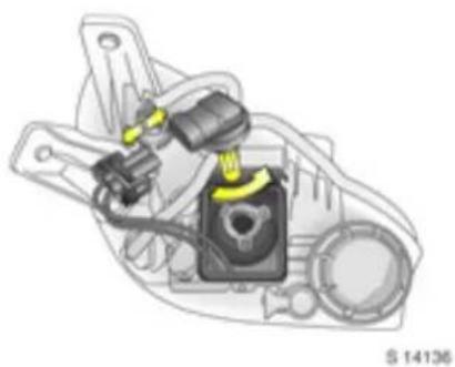
Low be am
- Open bonnet and remove 3 screws from headlamp protective cover.
- Rotate bulb soc ket a nti-clockwise and pull it out of head la mp assembly.
- Deta ch p lug connector from bulb socket.
- Remove bulb from bulb socket and insert new bulb, without touching the glass.
- Attach plug connector to bulb socket, push bulb socket into headlamp assembly and rotate bulb socket clockwise.
- Replace headlam p protective cover, replace 3 screws to hold cover in place and close bonnet.
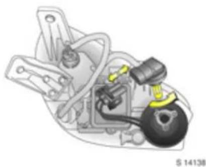
High beam
- Open bonnet and remove headlamp protective cover.
- Rotate bulb socket anti-clockwise and pull it out of headlamp assembly.
- Detach plug connector from b ulb socket.
- Remove bulb from bulb socket and insert new bulb, without touching the g la ss.
- Atta ch plug connector to bulb socket, push bulb socket into headlamp assembly and rotate bulb socket clockwise.
- Replace head lamp protective cover and close bonnet.
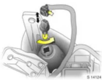
Parking lamps
- Open bonnet.
- Rotate bulb socket anti-clockwise and pull it out of headlamp assembly.
- Detach plug connector from bulb socket.
- Remove bulb from bulb socket and insert new bulb, without touching the glass.
- Attach p lug connector to bulb soc ket, push bulb socket into headlamp assembly and rotate bulb socket cloc kwise.
- Close bonnet.
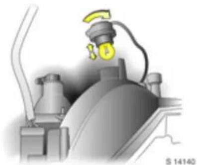
Front turn signals, front fog lamps
- Open bonnet.
- Reach through aperture between front panelling and bonnet and locate bulb assembly.
- Rotate bulb socket a nti-clockwise and pull out bulb assembly.
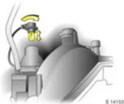
- Detach plug connector from b ulb socket.
- Remove bulb from bulb socket and insert new bulb, without touching the glass.
- Atta ch plug connector to bulb socket, push bulb assembly into original position and rotate bulb socket clockwise.
- Close bonnet.

Rear brake, tail, turn signal lam
- Open lug gage compartment
- Remove 2 bolts holding the bulb assembly to the vehicle body.
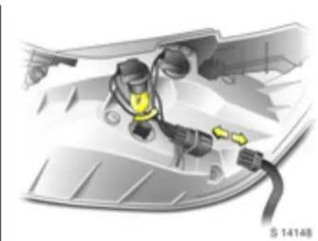
ps3. Pull bulb assembly away from vehicle body and detach plug connector from bulb assembly.
- Rotate bulb socket a nti-clockwise and remove from bulb assembly.
- Remove bulb from bulb socket and insert new bulb, without touching the glass.
- Replace bulb soc ket in bulb assembly and rotate bulb socket cloc kwise.
- Replace bulb assembly into original position and replace 2 bolts to hold bulb assembly to the vehicle body.
- C lose lug gage compartment.

Reversing lamp, fog tail lamp
- Reach behind, up and under rear panelling and locate bulb socket.
- Rotate bulb socket anti-clockwise and remove from lam p assembly.
- Remove bulb from bulb socket and insert new bulb, without touching the glass.
- Install bulb socket by lining up the tabs in the lamp assembly and rota te bulb socket clockwise.

License plate lamps
- Remove 2 screws holding license plate lampto fasda.
- Rotate and pull license plate lamp forwards through fascia op ening.
- Rotate bulb socket anti-clockwise.
- Remove bulb from bulb socket and insert new bulb, without touching the glass.
- Rotate bulb socket clockwise and replace license plate lamp into original position.
- Replace 2 screws to hold license plate lamp to fascia.
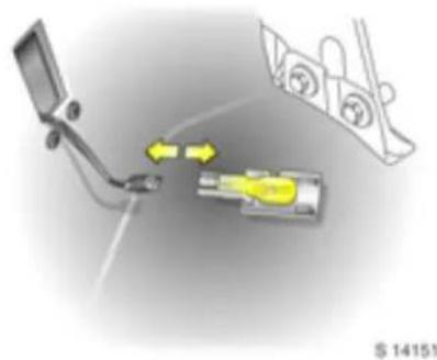
Luggage compartment lamp
- Open luggage e comp arment and prise out bulb housing.
- Deta ch plug connector from bulb housing.
- Remove bulb from bulb socket and insert new bulb, without touching the glass.
- Attach plug connector to bulb housing, push bulb housing into original position and close lugg age compartment.
Centre high-mounted stop lamp, side repeater lamps, courtesy lamps, instrument illumination
We re commend having bu lb replace men ts carried out by a workshop.
Inspection system
In order to guarantee economical and so fe vehic le operation and to maintain the value of your vehicle, it is of vital importance that all maintenance work is carried out at the proper intervals as speci fed by Ope I (see chapter "Serv ic e, Maintenance" on page 165). Tim e or mileage/kilometre intervals - w hichever is reached first - determine when your vehicle is due for its next Service.
Have the Service work that is due carried out within one week or 500 km (300 miles). Have this work carried out by a repairer in accordance with Opel's recommendations, using Opel genuine parts and accessories.

The engine oil life monitor lets you know when to change the engine oil. Based on driving conditions, the time or kilometer mileage interval at which an engine oil change will be indicated can vary considerably.
For the system to work properly, it must be reset every time the engine oil is changed. Seek the assistance of a workshop.
When the system has calculated that engine oil life has been diminished, "CHAN GE OIL SO ON" ap pears in the driver information centre - see page 69. Engine power may be decreased. Change engine oil immediately.
Further information on Service and the Service Plan can be found in the chapter "Service, M ainte nance" on page 165.
Have maintenance work, as well as repairs to the bodywork and equipment, carried out by a professional. We recommend your Opel Service Partner, who is familiar with Opel vehicle s and in possess sion of the necessary special tools and the latest service instructions from Opel. It is particularly advisable to use an Opel Service Partner during the warranty period, to avoid invalidation of warranty claims. See the chapter "Service, Maintenance" on page 165 for further information.
Sepa rate anti-c orrosion service
Have the work performed at the intervals specified in the chapter "Service, Maintenance" on page 165.
152 Self-help, vehicle care
Opel genuine parts and accessories
We recommend that you use "Opel genuine parts and accessories" and conversion parts released expressly for your vehicle type. These parts have undergone special tests to establish their reliability, safety and specific suitability for Opel vehicles. Despite continuous market monitoring, we cannot assess or guarantee these attributes for other products, even if they have been granted approval by the relevant authorities or in some other form.
"Opel genuine parts and a accessories" and approved conversion parts can be obtained from your Op el Service Partner, who can provide comprehensive advice about permitted technic al changes and ensure that the part is installed correctly.
17304 T
A note on safety
To avoid injury from moving parts and cables conducting ignition voltage, only carry out engine compartment checks (e.g. checking brake/clutch fluid or engine oil level) when the ignition is switched off.
⚠ Warning
The cooling fan is controlled by a thermos witch and can the refore start unexpectedly, even if the ignition is switched off. Risk of injury.
Electronic ignition system s use a very high voltage. Do not touch the ignition system; danger to life.

Never carry out any repairs or adjustment and maintenance work on the vehicle yourself. This especially applies to the engine, chassis and safety parts. You may, out of ignorance, infringe the provisions of the law and, by not performing the work properly, you may endanger yourself and other road users.
Checking and topping up fluids
The engine oil d lipstick handle and the information on the caps for topping up coolant and brak e/clutch fluid are yellow, for ease of identification.
Engine oil
Information on engine oils is available in the chapter "Service, Ma intenance" on page 165.
Engine oil level and consumption
Every engine consumes e ngine oil for tec hnical re asons . The engine oil consumption cannot be assessed until a fairly long distance has been driven, and may be a bove the spe cified value when the vehic le is first b eing driven (run-in period ) . Frequent driving at high revs increases engine oil consumption.
⚠ Warning
Do not allow the engine oil level to drop below the minimum level!
Before em barking on a long journey, it is advisable to check the engine oil level.

Engine oil lev el chec k, top ping up engi ne oil
The engine oil level must be checked with the vehicle on a level surface and with the engine (which must be at operating temperature) switched off. Wait at least 5 minutes before checking the level to allow the normal engine oil accumulation in the engine to flow into the oil pan.
To check the engine oil level, insert wiped oil gauge (dipstick) into dipstick tube as far as it will go. Top engine oil up if the level has dropped into the range of the top-up mark MIN.
The engine oil level must not exceed the upper mark MAX on the dipstick. Excess engine oil must be drained off or extracted. If the engine oil level is above the MAX mark there is a risk of damage to the engine or the catalytic converter.
Capacity between MIN and MAX marks – see page 182.

Top up with the same brand of engine oil that was used during the previous engine oil change, following the instructions in the chapter "Serv ice, Maintenance" on page 165.
To close, position the cap and screw it into place.
Ca pacities – see page 182.
Engine oil change, engine oil filter change Perform change in accordance with the chapter "Service, Maintenance" on page 165.
Engine oil changes are to be carried out depending on time or kilometre/mileage intervals, or when the engine oil life monitor indicates that engine oil life has been diminished, since engine oil loses its lubrication properties not only through engine operation but also through ageing.
We recommend using an original Opel engine oil filter.
⚠ Warning
Empty engine oil cans must not be placed in the domestic refuse. We recommend that you entrust engine oil and engine oil filter changes to a workshop who is familiar with the legal requirements concerning the disposal of used engine oil and filters, and can thus help protect the environment and your health.
Remember to reset the engine oil life monitor whenever the engine oil is changed. Seek the assistance of a work shop.
Coolant
During operation the sy ste m is pres su rize d. The tem perature may the re fore rise to over 100 °C.
The glycol-based coolant p rovid es excellent corrosion protection for the hea ting and cooling sy stems as well a s antifreeze protection down to -28°C . It remains in the cooling system throughout the year and need not be changed.
Use of certain antifreezes can lead to engine damage. We therefore recommend the use of antifreezes that have been approved.
⚠ Warning
Antifreeze is a danger to health; it must therefore be kept in the original container and out of the reach of children.

Antifreeze and corrosion protection Before the start of the cold weather season, have the coolant checked for correct concentration.
The a mount of antifreeze must provide protection up to ap prox. - 28 °C. If the antifreeze concentration is too low, this reduces protection from freezing and corrosion. Top up antifreeze if necessary.
If coolant loss is topped up with water, have concentration checked and add anti-fre ez e if ne cessa ry.
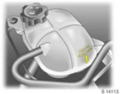
Coolant level
Hardly any losses occur since the cooling system is sealed and it is thus rarely necessary to top up the coolant.
The coolant should be just above the arrow marked COLD FILL in the expansion tank with a cold cooling system. The coolant level can be read from the outside of the expansion tank.
⚠ Warning
Allow engine to cool down before rem oving cool a nt filler cap. Rem ove filler cap carefully so that p ressure can escape slow ly, otherwise there is a risk of scalding.
When the engine is at operating temperature the coolant level rises. It falls again when the system cools. If it falls below the COLD FILL mark when the system is cold, top up to the mark.
Top up antifreeze. If no antifreeze is available, top up with clean tap water. If tap water is unavailable, distilled water can be used.
After topping up with drinking water or distilled water, c check the antifreeze level and a dd antifreeze if required. Have the cause of the coolant loss rectified by a workshop.
Too low a coolant level can cause engine damage.
To close, position the cap and screw it into place.
156 Self-help, vehicle care
Coola nt temperat ure
During operation the system is pressurized. The temperature may therefore rise to over 100 °C.
Control indicator 📁 illuminates in the instrument panel when coolant tem peratu re is too high. Check coolant level im mediately:
■ Coolant level low:
Top up coolant. Pay a tention to the instructions given under "Antifreeze and corrosion protection" and "Coolant level". Have the cause of coolant loss remedied by a workshop.
■ Coolant level OK:
Have the cause of increased coolant temperature remedied. Contact a work shop.

Brake and clutch fluid Brake and clutch fluid level
⚠ Warning
Brake/clutch fluid is poisonous and corrosive. Do not allow it to contact eyes, skin, fabrics or painted surfaces. Direct contact may cause injuries and da mage.
The fluid level in the container must be neither higher than the MAX mark nor lower than the MIN mark.
Use of certain brake/clutch fluids can lead to damage or reduced braking effect. We therefore recommend that you use only high perform and brake/clutch fluid app roved.
When topping up, ensure max imum cleanliness, as contamination of the b ra ke/clutch fluid can lead to function problems in the braking system.
After correcting the brake/clutch fluid level, have the cause of brake/clutch fluid loss remedied by a workshop.
Brake/clut ch fluid change
Brake/clutch fluid is hygroscopic, i.e. it absorbs water. If the brakes become hot, such as when driving on long downhill stretches, vapour bubbles can occur in the water, which can have an extremely adverse effect on braking power (dep ending on the proportion of water r).
The fluid change intervals specified in the chapter "Service, Maintenance" on page 165 m ust therefore be observed.
⚠ Warning
We recommend that you have brake/clutch fluid changed by a workshop who is familiar with the requirements of the law as regards disposal of brake/clutch fluid and can thus help to protect the environment and your health.

\$ 14116
Power steering fluid
The power steering fluid does not require any additional ma intenance than that detailed in the chap ter "Service, Maintenance" on page 165.
If the fluid in the reservoir falls below the HOT mark on the dipstick, consult a workshop.
Windscreen wipers
Clear vision is essential for safe driving.
Perform regular checks on the windscreen wipers to ensure they are operating correctly. We recommend wiper blade replacement at least once a year.
If the windsc re en is dirty, operate the windscreen washer system before switching on the windscreen wipers. This will avoid wiper blade wear.
Do not switch on the windscreen wipers if the wind screen is iced up, as this could damage the wiper blades or the wiper system.
If the wipers become frozen on to the glass, we recommend that they be released with the aid of O pel De -icer Spray.
Smearing wiper blades can be cleaned with a soft cloth and Opel Cleaning Solvent and Antifreeze.
Wiper blades whose lips have become hardened, crack ed or covered with silicone must be replaced. This may be necessary as a result of the effects of ic e, thawing salt or heat, or the incorrect use of cleaning agents.
Switch h off the windscreen w ip ers in car washes – see pages 15, 161.
Windscreen w ip er care – see p age 163.
158 Self-help, vehicle care
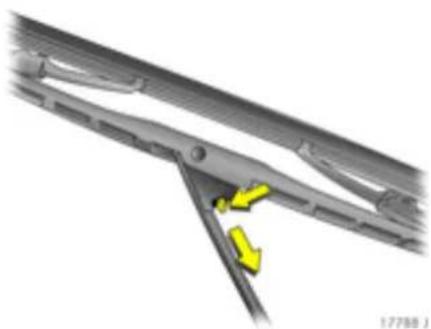
To replace wiper blade, lift wiper arm away from windscreen. Move release lever and detach wiper blade.

Windscreen washer system
The fluid reservoir filler neck for the wind scre en was he r sy ste m is lo cate d in the engine com partment.
Capacities – see page 182.
Fill only with clean water to prevent the nozzles from clogging. To improve cleaning efficiency, we recommend that you add a little Opel Cleaning Solvent and Antifreeze.
The wind screen washer system will not free ze in winter.
| Freeze protection down to | Mixture - Op el Cleaning Solvent And Antifreeze : Water |
| - 5 °C 1 : 3 | |
| - 10 °C 1 : 2 | |
| - 20 °C 1 : 1 | |
| - 30 °C 2 : 1 |
When closing the container, press the lid firmly over the bea ded edge all the way round.

173201
Battery
The b attery is m ainte nanc e-free .
⚠ Warning
Have battery changes carried out by a workshop who knows the laws concerning the disposal of used batteries and therefore protects the environment and your health.
Retrofitted electric or electronic accessories can place an additional load on the battery or even discharge the battery. Consult a workshop regarding technical possibilities, such as fitting a more powerful battery.
Laying up the vehicle for more than 4 weeks can lead to battery discharge, which may reduce the service life of the battery. Disconnect battery from on-board power supply by detaching negative terminal.
Ensure that the ignition is switched off before connecting battery. Then perform the following actions:
■ Set date and time in the radio display – see section "Infotainment system ✦" on page 78.
In order to prevent the battery from disch argin g, some con su mer s such as the courtesy lamps automatically switch off after approx. 20 minutes.
Protection of electronic components
In order to prevent faults in electronic components in the electrical system, never connect or disconnect battery with the engine running or the ignition switched on. Never start engine with battery disconnected, e.g. when starting using jump leads.
To avoid damaging the vehicle, do not make any modifications to the electrical system, e.g. connecting ad ditional consumers or tampering with electronic control units (chip tuning).
Warning
Electronic ignition systems use a very high voltage. Do not touch the ignition system; doing to life.
Disconnecting/connecting the battery from /t o the electrical system
Disconnect the battery from the vehicle electrical system before charging: First detach the negative and then the positive lead. Do not reverse the polarity of the battery, i.e. do not confuse the term in a is for the positive and negative leads. When connecting, start with the positive lead and then connect the negative lead.
Vehicle decomm issioning
Observe na tional regulations.
If the vehicle is decommissioned for seven months, the following work must be carried out by a workshop in order to prevent dam age.
■ Wash and preserve the vehicle – see page 161.
■ Check preservation in engine compartment and on underbody and make good where necessary.
■ Clean and preserve rubber seals on bonnet and doors.
■ Change engine oil – see page 154.
- Check antifreeze and corrosion protection – see page 155.
- Check the coolant level, top up with antifreeze if necessary – see page 155.
■ Empty wind dsc re en w ash e r sy ste m.
■ Increase tyre pressures to value specified for full load – see page 180.
Vehicle storage
■ Park vehicle in a dry, well ventilated place. Engage first or reverse gear. Use chocks or the like to prevent the vehicle from rolling.
■ Do not apply hand brake.
■ Disconnect battery by disengaging negative terminal from vehicle electrical system – see page 159.
Vehicle recommissioning
Observe national regulations.
Perform the following work before recommissioning the vehicle:
■ Connect battery – see page 159.
- Check tyre pressures and correct if necessary – see page 180.
■ Fill up w indscreen washer system – see page 72.
■ Check engine oil level – see page 153.
- Check the coolant level; top up with antifreeze if necessary – see page 155.
Fit the license plate if necessary.
Vehicle care
When caring for your vehicle, observe all national environmental regulations, particularly when washing it.
Regula r, thorough care helps to improve the appearance of your vehicle and maintain its value over the years. It is also a prerequisite for warranty claims for any paint or corrosion damage. The following pages contain tips for vehicle care which, if used properly, will help combat the unavoidable damaging effects of the environment.
Vehicle care aids *
Vehicle wash:
■ Wash brush,
Car Shampoo,
■ Sponge s,
■ Wheel Cleaners,
■ Engine Cleaners,
■ Glass Clea ners,
■ Insect Removal Sponge,
■Chamois Leather.
Vehicle care:
■ Paintwork Cleaner,
■ Paintwork Polish,
■ Cream Polish,
■ Metallic Paintwork Wax,
■ Hard Wa x,
■ Touch-U p Applicator,
■ Aerosol and Touch-Up Paint,
■ Lock Cylinder Grease,
■ Wheel Pre serve r,
■ Alloy Whee I Pres erve r
■ Tar Removal Spray,
■ Insect Remover,
■ Window Cleaner,
■Cleaning Solvent and Antifreeze,
■ Silicone Oil for Rubber Seals.
Interior care:
■ Interior/Upholstery Cleaner.
Washing
The paintwork of your vehicle is exposed to environmental influences, e.g. continuous changes in weather conditions, industrial waste gases and dust or thawing salts, so wash and wax your vehicle regularly.
Bird droppings, dead insects, resin, pollen and the like should be cleaned off immediately, as they contain aggressive constituents which can cause paint damage.
If using a car wash, comply with the pertinent instructions of the car wash ma nufacturer. The win dscre en wipers must be switched off – see pages 15, 71. Remove antenna by unscrewing anti-clockwise.
If you wash your vehicle by hand, make sure that the inside of the wings are also thoroughly rinsed out.
Clean edges and folds on opened doors and flaps as well as the a reas they cover.
Thoroughly rinse off a nd leather-off the vehicle. Rinse leather frequently. Use sepa ra te leathers for paint and window surfaces: remnants of wax on the windows will im pair vision.
Observe national regulations.
Soft top car e
Particular care should be taken when washing the fabric soft top. Carefully vacuum the soft top before washing, to remove excess dust and dirt articles. Wash in shade with a sponge (a chamois lea ther will leave lint, while a brush may abrade the threads) and use an Opel Car Shampoo and lukewarm water solution.
Wash the entire top uniformly to avoid rings or spots. Rinse with plenty of clean water.
Remove surface water with a sponge and allow to air dry. Be sure to allow the soft top to dry completely before stowing, as prolonged stowage of a wet or damp soft top will cause rotting of the fabric.
■ Remove bird droppings from the soft top immediately.
■ Do not use aggressive cleaning agents or stain removers.
■ Do not direct water jets on to the edges of the soft top.
■ Do not use sharp-edged objects to remove snow and ice from the soft top.
Whilst the soft top is weatherp roof, it cannot be guaranteed to be fully waterproof if the vehicle is washed in an automatic car wash. It is therefore recommended that the vehicle is hand-washed and that automatic car washes are avoided.
Exterior stor age
Due to the soft top design being weatherproof and not water tight in all conditions, extended periods of rainfa ll ma y result in some e w ater collection in the passenger r compartment. Therefore, it is recommended that the vehicle is not stored outside without a suitab le protective covering such as a shower cover (available from your Opel Service Partner).
Waxing
Wax your vehicle regularly, in particular after it has been washed using shamp oo and a t the latest w hen water no longer forms beads on the paintwork, otherwise the paintwork will dry out.
Never let things deteriorate this far. Waxing prevents harmful chemical action.
Also wax edges and folds on opened doors and flaps as well as the a reas they cover.
Polishing
Polishing is necessary only if the paint has become dull or if solid deposits have become attached to it.
Paintwork polish with silicone forms a protective film, making waxing unnecessary.
Plastic body parts must not be treated with preservation and polishing a gents.
Use Metallic Paintwork Wax on vehicles with a metallic-effect paint finish.
Wheels
Use a pH-neutral wheel cleaning agent to clean the wheels.
Wheels are painted and can be treated with the same agents as the body. For alloy wheels, we recommend the use of Alloy Wheel Pre serve r.
Paintwork da mage
Repair small areas of paint damage such as stone impacts, scratches etc. immediately using a Touch-Up Applicator or Aerosol and Touch-Up Paint before rust can form. If rust has already formed, have the cause rectified by a workshop. Please also pay attention to surfaces and edges be neath the vehicle where rust may have formed unnoticed for some time.
Tar spots
Do not use hard objects to remove spots of tar – use Tar Removal Spray. Do not use Tar Removal Spray on the covers of headla mps or other exterior lamps.
Exterior lamps
Headlamp and other protective lamp covers are made of plastic. If they re additional cleaning after the vehicle has been was hed, clean them with Car Shamp oo. Do not use any abra sive or caustic agents, do not use an ice scraper, and do not clean them dry.
Plastic and rubber parts
For additional cleaning of plastic and rubber parts, use Interior/Upholstery Cleaner. Do not use any other agent, and in particular do not use solvents or petrol.
Do not use high -pre ssure je t clea ne rs.
Wheels and tyres
Do not use high -pre assure jet cleaners on wheels and tyres.
Interior and upholstery
Clean the vehicle interior, including the instrument panel fascia, using Interior/Upholstery Cleaner.
The instrument panel should only be cleaned using a soft damp cloth.
Clean fabric upholstery with a vacuum cleaner and brush. To remove stains, use Interior/Upholstery Cleaner t hat is suitable for both fabrics and vinyl.
Do not use cleaning agents such as acetone, carbon tetrachloride, paint thinner, paint remover, nail varnish remover, washing powder or bleach to clean fabrics, carpets, the instrument pad or feather trim * in the vehicle interior. Petrol is also unsuitable.
Open Velcro fasteners on clothing could damage seat upholstery. Make sure that Velcro fasteners are closed.
Seat belts
Always keep seat belts clean and dry.
Clean only with lukewarm water or Interior/Upholstery Cleaner.
Windows
When cleaning the heated rear window, make sure that the heating element on the inside of the window is not damaged.
Use a soft lint-free cloth or chamois leather in conjunction with Window Cleaner and Insect Remover.
O pel Clea ning Solv ent an d Antifree ze is suitable for de-icing windows.
For mecha nical removal of ice, use a comm ercially available sharp-edged ice scraper. Press the scraper firmly against the glass so that no dirt can get under it and scratch the glass.
Windscreen wiper blades
W ax such as the wax us ed in car washes can cause sm earing on the wind scre en when the windscreen wipers are switched on.
Smearing wiper blades can be cleaned with a soft cloth and Opel Cleaning Solvent and
Antifreeze, and replaced if necessary – see page 157.
Locks
The locks are lubricated with a high-grade lock cylinder grease at the factory. Opel Lock Cylinder Grease prevents the locks from free zing up. Only use de-icing agents in emergencies, as they have a degreasing effect and will impair the function of the locks. After using a de-icing agent, have the locks re-greased by a workshop.
Eng ine compar tment
Areas of the engine compartment that are painted in the same colour as the vehicle must be looked after like any other painted surface.
It is adv isable to was h the e nginecompartment before and after winter and preserve it with wax. Cover alternator and brake/clutch fluid reserv oir with plastic sheets before washing the engine.
When washing the engine with a steam-jet cleaner, do not direct the steam-jet a t components of the Anti-lock Brake System (ABS), a ir conditioning system, climate control system or the b elt drive and its components.
Protective wax that has been applied is also removed during the engine wash. For this reason, have the engine, brake system components in the engine compartment axle components with steering, body parts and cavities thoroughly preserved by a workshop using protective wax.
An engine wash can be performed in the spring in order to remove dirt that has adhered to the engine compartment, which may also have a high salt content. Check protective ax layer and make good if necessary.
Do not use high-pressure je t clea ne rs.
Underbody
Your vehicle has a durable protective coating in the wheel arches (including the longitudinal members), which provides permanent protection and needs no special maintenance.
On ve hicle s which are washed frequently in automatic car washes with underbody washing facility, the protective coating may be impaired by dirt-dissolving add itiv es, so check the underb od y after washing and have it waxed if necessary. Before the start of the cold weather season, check the coa ting and, if necessary, have it restored to perfect condition.
Caution – commercially available bitumen/rubber materials can damage the coating. We recommend that you have underbody work carried out by a workshop, who knows the prescribed materials and has experience in the use thereof.
The underbody should be washed following the end of the cold weather season to remove any dirt adhering to the underbody since this may also contain salt. Check protective wax coating and, if necessary, have it restored to perfect condition.
Service, maintenance
European service schedule ..... 16 6
International service schedule..... 168
Additional servicing..... 170
Recommended fluids, and lubricants 170
European service intervals
Main Serv ice
Due e very 30,000 km (20,000 miles) or
1 year, whichever occurs first.
International service intervals
Interim Service
Due e very 15,000 km (10,000 miles).
Main Serv ice
Due e very 30,000 km (20,000 miles) or
1 year, whichever occurs first.
Engine oil life monitor - see pages 63, 69, 151.
Confirmations
Confirmation of Service is recorded in the spaces p rovided in the Service and Warranty Booklet. The date and kilometre/ mileage reading is completed with the stamp and signature of the Servicing Workshop.
Make sure that the Service and Warranty Booklet is completed correctly as continuous proof of service is essential if any warranty or goodwill claims are to be met, and is also a benefit when you come to sell the vehicle.
Service plan
The European serv ice sched ule is valid for the following countries:
Andorra, Austria, Belgium, Cyprus, Czech Republic, Denmark, Estonia, Finland, France, Germany, Greece, Greenland, Hungary, Iceland, Ireland, Italy, Latvia, Lithuania, Luxembourg, Malta, The Netherlands, Norway, Poland, Portugal, Slovakia, Slovenia, Spain, Sweden, Switzerland, United Kingdom.
For all remaining countries the International service schedule applies.
European service schedule
(Opel GT - Z 20 NHH)
| Service operations | by year1)km ( x 1000)miles ( x 1000) | 13020 | 26040 | 39060 | 412080 | 5150100 | 6180120 |
| Controls, lighting , signa lling equipment and airbags: visual check steering lock and ignition lock: check | x | x | x | x | x | x | |
| Remote control batteries: replace Every 2 years | |||||||
| Windscreen wipers, windscreen washer system: check, correct x x x x x x | |||||||
| Coolant level and antifreeze: check, correct Hoses: check for tightness and secure seating | x | x | x | x | x | x | |
| Brake fluid level: check, correct x x x | |||||||
| Battery terminals: check for secure connections and battery eye | x | x | x | x | x | x | |
| Pollen filter: replace | x | x | x | ||||
| ● More often for when dust, sand or pollen is in the air | Agreement with customer | ||||||
| Air cleaner element: replace | Every 4 years/60 000 km/40 000 miles | ||||||
| ⊕ Spark plugs: replace | Every 4 years/60 000 km/40 000 miles | ||||||
| Ribbed V-belt: visual check | x | x | x | ||||
| ⊕ Replace | Every 10 years/150 000 km/100 000 miles | ||||||
| Power steering system: check for leaks. Fluid level: check, correct | x | x | x | x | x | x | |
| Engine oil and oil filter: replac e2) | x | x | x | x | x | x | |
| Parking bra ke: check and adjust Wheel mounting and suspension front and rear, brake lines, brake pressure hoses, fuel lines and exhaust system: visual check | x | x | x | ||||
1) Whichever o cc urs fi rs t.
2) Engine oil life monitor may indicate an earlier engine oil and oil filter change is necessary. See pages 63, 69, 15 1.
⊕Additional o perations.
● Under extreme operating conditions and if required by country-specific conditions, the intervals are reduced.
| Service operations | by year 1) km ( x 1000)miles ( x 1000) | 13020 | 26040 | 39060 | 412080 | 5150100 | 6180120 |
| Corrosion protection: check and record in Servic e and Warranty Booklet Annually | |||||||
| Front and rear wheel b ra kes: check visually x x x | |||||||
| ●⊕ Annual service check if annual mileage exceeds 20 000 km | Annually | ||||||
| Engine, transmission, A/C compressor: check for leaks | x | x | x | x | x | x | |
| Steering system boots, track rods, final drive: visual check | x | x | x | x | x | x | |
| Track rod end and supporting ball joint: check | x | x | x | x | x | x | |
| ⊕ Brake and clutch fluid: change | Every 2 years | ||||||
| ⊕ Wheel fastening: loosen and tighten to torqueTyre condition a nd pressures: check, correct | x | x | x | x | x | x | |
| ⊕ Annual service check if annual m ileage exceeds 20 000 km Annually | |||||||
| First aid kit, tyre rep air kit and lashing eyes: visual check | Every 2 years | ||||||
| Headlamp aiming: check, adjust | x x x | ||||||
| ●⊕ Door hing es, door stop , lock c ylind er, lock striker, bonnet catch, tailgate hinges and check links: lubricate | x | x | x | ||||
| Folding roof: lubricate (in dusty conditions) | x | x | x | x | x | x | |
| Test drive, final checkService interval display and oil life m onitor: reset - if applicable | x | x | x | x | x | x | |
1) Wh iche ver o cc ur s firs t.
⊕Additiona | operations.
● Under extreme operating conditions and if required by country-specific conditions, the intervals are reduced.
International service schedule
(Opel GT - Z 20 NHH)
| Service operations by year1)km ( x 1000)1)miles ( x 1000)1) | 13020 | 4530 | 26040 | 7550 | 39060 | |
| Controls, lighting , signa lling equipment and airbags: v isual check steering lock and ignition lock: check | x | x | x | x | ||
| Remote control batteries: replace Every 2 years | ||||||
| Windscreen wipers, windscreen washer system: check, correct x x x x x x | ||||||
| Coolant level and antifreeze: check, correct Hoses: check for tightness and secure seating | Annually | |||||
| Brake fluid level: check, correct x x | ||||||
| Battery terminals: check for secure connections and battery eye | Annually | |||||
| Pollen filter: replaceMore often for when dust, sand or pollen is in the air | Every 2 years/60 000 km/40 000 milesAnnually/15 000 km/10 000 miles | |||||
| Air cleaner element: replaceMore often for when dust or sand is in the air | Every 4 years/60 000 km/40 000 milesAnnually/15 000 km/10 000 miles | |||||
| ⊕ Spark plugs: replace | Every 4 years/60 000 km/40 000 miles | |||||
| Ribbed V-belt: visual checkReplace | Every 2 years/60 000 km/40 000 milesEvery 10 years/150 000 km/100 000 miles | |||||
| Power steering system: check for leaks. Fluid level: check, correct | Annually | |||||
| Engine oil and oil filter: replac e2) | x | x | x | x | ||
| Parking bra ke: check and adjustWheel mounting and suspension front and rear, b rake lines, brake pressure hoses, fuel lines and exhaust system: visual check | Every 2 years/60 000 km/40 000 miles | |||||
1) Whichever o ccur s firs t.
2) Engine oil life monitor may indicate an earlier engine oil and oil filter change is necessary. See pages 63, 69, 15 1.
⊕Additional o perations.
● Under extreme operating conditions and if required by country-specific conditions, the intervals are reduced.
| Service operations | by year 1) km ( x 1000)miles ( x 1000) | 1301510 | 4530 | 26040 | 7550 | 39060 |
| Corrosion protection: check and record in Service and Warranty Booklet Annually | ||||||
| Front and rear wheel brakes: check visually | Every 2 years/60 000 km/40 000 miles | |||||
| ●⊕ Annual service check if annual mileage exceeds 20 000 km | Annually | |||||
| Engine, transm ission, A/C compressor: check for leak s Annually | ||||||
| Steering system boots, track rods, final drive: visual check Annually | ||||||
| Track rod end and supporting ball joint: check | Annually | |||||
| ⊕ Brake and clutch fluid: change | Every 2 years | |||||
| ⊕ Wheel fastening: loosen and tighten to torqueTyre condition and pressures: check, correct | Every 2 years/60 000 km/40 000 miles | |||||
| ⊕ Annual service check if annual m ileage exceeds 20 000 km Annually | ||||||
| First aid kit, tyre rep air kit and lashing eyes: visual check | Every 2 years | |||||
| Headlamp aiming: check, adjust | Every 2 years/60 000 km/40 000 miles | |||||
| ●⊕ Door hing es, door stop , lock cylind er, lock striker, bonnet catch, tailgate hinges and check links: lubricate | Every 2 years/60 000 km/40 000 miles | |||||
| Folding roof: lubricate (in dusty conditions) | Annually | |||||
| Test drive, final checkService interval display and oil life monitor: reset - if applicable | x | x | x | x | x | |
1) Wh iche ver o cc ur s firs t.
⊕Additiona | operations.
● Under extreme operating conditions and if required by country-specific conditions, the intervals are reduced.
Additional servicing
Additional operations ⊕
Additional work is work that t is not required every service but can be performed in conjunction with a regular service.
Time allowances for such work are not included in the scope of regular services and will be charged for add itionally. It is more economic if these operations are performed as part of a scheduled service than having them performed separately.
Severe operating conditions ●
Operating conditions are classified as severe when one or more of the following occurs frequently:
■ cold starts,
■ stop and go,
■ trailer/caravan towing,
■ gradients and/or high altitudes,
■ poor road surfaces,
■ sand and dust,
■ extreme temperature fluctuations.
Police vehicles, ta xis and driving school vehic les are also cla ssified as operating under severe conditions.
Under severe operating conditions, it may be necessary to have certain scheduled service work done more frequently than the scheduled intervals.
For example, if fuel is used that does not comply with required standard rd s, the fuel filter may need more frequent draining or rep la cement and it may also be necessary to change other components more often (e.g. spark plugs).
It is recommended to seek technical advice on the servicing requirements dependent on the specific operating conditions of your vehicle.
Recommended fluids, and lub rica nts
Only use products that have been tested and approved. Damage resulting from the use of non-approved materials will not be covered by the warranty.
Warning
Operating materials are hazardous and must be hand led with the appropriate level of ca re. If consumed, seek medical attention immediately. Do not inhale fumes and avoid skin contact. Keep out of reach of children. Do not allow opera ting materials to contaminate the sewage system, surface water, ground water or soil. Dispose of empty containers properly. Always bear in mind that opera ting materials are hazardous to your health.
Checking and topping up fluids see page 152.
Eng ine oil
Engine oil is identified by its quality and also its viscosity. Quality is more important than viscosity when selecting which engine oil to use.
Engine oil quality
European specificat ions
GM-LL-A-025: Petrol engines
| GM General Motors Europe |
| LL Longlife |
| A Engine oil quality specification |
| 025 Validity index |
O pel e ng ine oil me ets classification GM -LL-A-025 and is therefore suitable for petrol engines.
Int erna tional specific ations
ACEA-A3: Petrol engines
The above specification is valid only if the service interval is reduced to that shown for the international service schedule - see page 165.
Topp ing up engine oil
Oils of different manufacturers and brands can be mixed as long as you comply with the specified engine oil criteria (quality and viscosity).
N ot eve ry e ngin e oil ava ila ble on the mark et mee ts the quality requirements, always check the req uired specification and ra ting is marked on the container.
If engine oil of the required quality is not available, a maximum of 1 litre of ACEA A3/B4 or A3/B3 grade may be used (only once between each oil change). The viscosity should be of the correct rating.
Use of ACEA A1/B1 and A5/B5 engine oil is expressly forbidden, since they can cause long-term engine damage und er certain operating conditions.
Engine oil additives
The use of engine oil additives could cause damage and invalidate the warranty.
Eng ine oi I viscosity
SAE 0W-30, 0W-40, 5W-30 or 5W-40
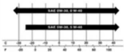
S 17639
The SAE viscosity rating defines the ability of an oil to flow. When cold, oil is more viscous than when hot.
Multigrade oil is indicated by two figures. The first figure, followed by a W, indicates low temperature viscosity and the second figure the high temperature viscosity.
Coolant and antifreeze
Use antifreeze of recommended specification: silicate-free LLC (Long Life Coolant).
The system is factory-filled with coolant designed for frost protection down to approx. -28 °C. This concentration should be maintained all year-round.
Coolant additives intend ed to give additional corrosion protection or seal against minor leaks can cause function problems. Liability for consequences resulting from the use of coolant a dditives will be rejected.
Brake and clutch fluid
Only use DOT3 or DOT4 brake fluid.
Warning
Brake fluid is poisonous!
Over time, brake fluid absorbs moisture which will reduce braking effectiveness. The brake fluid should therefore be replaced at the specified interval.
Brake fluid should be stored in a sealed container to avoid water absorption.
Ensure it does not become contaminated with fluids containing mineral oil (oil, petrol, cleaner) as this can damage the seals and sleeves of the brake system.
Warning
Due to its corrosive nature, it must not come in contact with the paintwork. Flush any escaped b rake fluid with p lenty of water.
172 Technical data
Technical data
Vehicle documents, 172 Identification plate
The technical data is determined in accordance with European Community standards. We reserve the right to make modifications. Specifications in the vehic le documents always have priority over those given in this manual.
The vehicle identification number (VIN) stamped on a plate and is affixed to the instrument panel on the driver's side, visible through the windscreen.
183
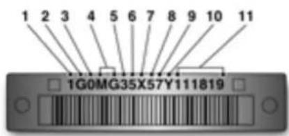
\$ 14711
Information on visib le VIN plate: Vehicle docum ents
- Country of origin
- Manufacturer
- Make
- Carline/Series
- Body style
- Restraint system
- Engine type
- Check digit
- Model year
- Plant location
- Plant sequence number
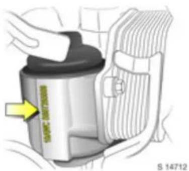
Engine identification: etc hed into the engine oil filter housing on the cylinder block.

The VIN and axle loading information label is located on the B-pilla r, visible with the driver's door open.
Information on label:
- Manufacturer
- Type approval number
- Vehicle identification number
- Gross vehicle weight rating
- Permis sible gros s train we ight
- Maximum permissible front axle load
- Maximum permissible rear axle load

Vehicle identification data
The tyre and loading information label is located on the B-pillar, visib le with the driver's door open. See page 126.
Information on label:
■ Specified occupant sea ting positions
■ Maximum vehicle capacity weigh ht
■ Vehicle identification number (VIN)
■ Tyre pressure, front and rear
■ Original equipment tyre size
174 Technical data
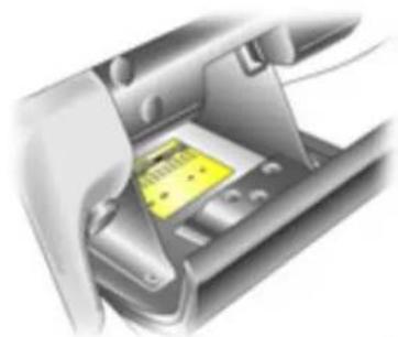
§ 14171
The service parts identification label is located in the glove compartment.
Information on la bel:
■ Vehicle option code
■ Vehicle identification number (VIN)
■ Engineering model number (v vehicle division, line and body style)
■ Interior trim level and decor
■ Exterior (paint colour) WA number
■ Paint technology
■ Spec ia l ord er paint colours a nd numb ers
Coo lant, oils, b rake/clu tc h fluid
Use approved fluids only.
Use of unsuitable fluids could cause serious damage to the vehicle.
Engine oils
Information on engine oils is available on page 170.
| Engine data | |
| Sales designation | 2.0 Turbo |
| Engine stamp | LNF |
| Engine identifier code | Z 20 NHH |
| Numb er of cylinders 4 | |
| Bore dia. (mm) 86 | |
| Stroke (mm) 86 | |
| Piston displacement (cm3) 1998 | |
| Engine power (kW) | 194 |
| at rpm | 5300 |
| Torque (Nm) | 353 |
| at rpm | 2500-5000 |
| Com pression ratio 9.2 : 1 | |
| Fuel type 1) | Petrol |
| Octane requirement (RON) | |
| un leaded | 95 (S) |
| or un le aded | 98 (SP) |
| Max . pe rmissible engine spe ed, continuous (rpm) ap prox. 6300 | |
| Oil consumption (l/1000 km) | 0.6 |
1) Standard high-quality fuels, unleaded DIN EN 2 28.
2) Standard high-quality fuels: S = Super (Premium). SP = Super Plus (Premium Plus): value printed in bold: recommended fuel.
3) Knock control system automatically adjusts ignition timing according to type of fuel used (octane number).
176 Technical data
Performance
(approx. km/h / mph)
| Engine1) | Z 20 NHH |
| Maximum speed2) | |
| Manual transmission | 229/142 |
1) Sa les desig nat ion – see page 17 5.
2) The maximum speed indicated is achievable at kerb weight. Optional equipment could reduce the specified maximum speed of the vehicle.
Fuel consumption, CO₂ emissions
Directive 80/1268/EEC (last changed by 2004/3/EG) has applied for the measurement of fuel consumption since 1996.
The directive is oriented to a actual driving practices: Urban driving is rated at ap prox.
1/3 and off-road driving with approx. 2/3 (urban and extra-urban consumption). Cold starts and acceleration phases are also taken into consideration.
The specification of CO2 emission is also a constituent of the directive.
The figures given must not be taken as a guarantee for the actual fuel consumption of a particular vehicle.
All values are based on the EU base model with stand ard equipment.
The calculation of fuel consumption as specified by directive 2004/3/EG takes account of the vehicle's kerb weight, ascertained in accordance with these regulations. Optional extras may result in slightly higher fuel consumption and CO 2 emission levels than those quoted.
To convert l/100 km into mpg, divide 282 by num ber of litres /100 km.
Saving fuel, protecting the environment see page 112.
Fuel consumption (approx. l/100 km), CO 2 emission (approx. g/km)
| Engine1) | Z 20 NHH |
| Manual transmission | |
| urban | 13.0 |
| extra-urban | 6.9 |
| total | 9.2 |
| CO2 | 218 |
178 Technical data
Weights, payload and roof load
The p ayload is the diffe rence betwe en the permitted gross vehicle w eight (see vehicle identification data, p age 173) and the EC kerb weig ht.
To calculate the kerb weight, enter the data for y our vehicle below:
■ Kerb weight from Table 1 +.... . kg
■ We ight of heavy accessorie s
The total =..... . kg
is the EC k erb w eight.
Optional equipment and accessories increase the kerb weight, which means that the p ayload will also change slightly.
Note the weights given in the vehicle documents.
The c om bined total of front and rear axle loads m ust not ex ceed the permissible gross v ehi cle weight. For example, if the front axle is b earing its maxim um permissible loa d, the rear axle can only bear a load that is equal to the gross vehicle weight minus the front axle load.
For permitted axle loads, see vehicle identification data and vehicle documents.
Roof load
Roof loads are not permissible.
Weights (kg), Table 1, Kerb weight
| Engine1) | Manual transmission2) |
| Z 20 NHH | 1406 - 1446 |
.... .... .... . kg
1) Sales designation – s ee page 175.
2) According to EC Directive, including assumed weights for driver (68 kg), luggage (7 kg) and all fluid s (tan k 90 % full).
Tyres
Restrictions
Tyres of size 245/45 R 18 may only be used
Goodyear Eagle F1 GS-2 P 245/45
R 18 96 W and Bridgestone Potenza
RE050A 245/45 R 18 100 W are
recom mende d for this v ehicle. These ty res have und ergone special tests to establish their reliability, safety and specific
suitability for Opel vehic les.
Not all tyres available on the market currently me et the s tructural requirements.
Seek the assistance of a workshop concerning suitable tyre makes.
Des pit e contin u o us mark et mo n ito ring, we are unable to assess these attributes for other tyres, ev en if they have been granted approval by the relevant authorities or in
some other form.
Further information – see page 125.
Wint er tyre s *
Tyres of size 245/45 R 18 are permitted for us e as win te r tyre s.
Use only specified winter tyres released for
your vehicle. Seek the assistance of a workshop.
Further information – see page 129.
Tyre chains ✿
Restrictions
Tyre chains may be used on the rear wheels only.
We recommend the use of Ope I-tes ted fine-mesh tyre chains that add no more than 11 mm to the tyre tread and the inboard sides (including chain lock).
Further information – see page 129.
Wheels
Wheel bolt tightening torque: 140 Nm.
180 Technical data
Tyre pressure in kPa/bar
The specified tyre pressures are valid for cold tyres. The increased tyre pressure resulting from extensive driving must not be reduced. The tyre pressures specified in the following table apply to both summer and winter tyres.
Further information – see pages 125 to 129.
| Tyre pressure with full load | ||
| Engine1) | Tyres | Front |
Z 20 NHH 245/45 R 18 200/2.0 200/2.0
1) Sales designation – s ee page 175.
Electrical system
Battery Voltage 12 Volt
Amp hours 60 Ah
Battery for remote control CR 20 32
182 Technical data
Capacities
(approx. litres)
| Engine1) | Z 20 NHH |
Engine coolant 9.0
Fuel tank (nominal content) 52.0
| Engine oil with filter change | 4.7 |
| between MIN and M AX on dipstick | 1.0 |
Washer fluid reservoir for windscreen washer system 4.5
Dimensions
| Overall length (mm) 4100 | |
| Overall width (mm) 1813 | |
| Overall width including exterior mirrors (mm) 1846 | |
| Overall height with soft top raised (mm) 1276 | |
| Wheelb ase (mm) 2415 | |
| Track width (mm): | |
| Front | 1543 |
| Rear | 1561 |
| Turning circle diameter, kerb to kerb (m) 10.5 | |
Index A
AB S (Anti-lock Brake System) ..... 124
Air conditioning system ..... 107
Anti-knock quality of fuel .... 114
Octane number .... 175
Anti-theft protection ..... 9, 17
Interruption of power supply ..... 23
54Batte ry discharge protection ..... 77
Before starting-off ..... 16
Belt force limiters .... 40
Central locking system 6,24
Centre high-mounted stop lamp ..... 150 Bulb replacement ..... 150
Changing the battery Remote control .... .... .... .... 23, 181
Child restraint systems .... 44
Ciga rette lig hter ..... 53, 77
Clim ate control .... 102
Clutch fluid ..... 156
Clutch operation ..... 111
CO₂ emissions ..... 17
ABS (Anti-lock Brake System) ..... 55, 1
Airbag system s .... 47,57
Engine oil pressure ..... 57
ESC (Electronic
Stability Control) .... 58, 1 19
ESP (Electronic
Fog tail lamp ..... 55, 75
Front fog la mps ..... 58, 75
High be am .... 56
Immobiliser ..... 2 2, 58
Luggage compartment open ..... 55
Passenger's seat belt .... 43
Seat occupancy recognition .... .... .. 48
Bulb replacement 150
Cruise control ..... 1 21
D
Dashboard - see Instrum ent panel ..... 10
Decommissioning ..... 160
Demisting a nd defrosting ..... .... 16, 106
Dimensions .... 183
Door locks .... 6, 26, 164
Driver information centre ..... 19, 59
Driver's se at belt warning dev ice .... 43, 57
Driving ab road ..... 114
Economical driving ..... 112
Electric windows .... 30
Electrical system .....141, 159, 160, 181
Electronic Stability Control (ESC) ..... 118
Em emergency luggage compa rtm ent
Engine oil .... 153, 170
Ad ditiv es .... 171
Topp ing up .... .... .... .... .... ....
Viscosity .... 1
Engine oil change .... 154
Engine oil level and consumption .... 153
Engine oil life monitor ..... 63, 151
Engine oil pressure .....57
Engine speed ..... 111
Engine wash .... 164
First-a id kit 53,135
Flat ty re ..... 135, 136
Fog tail lamp ..... 13, 75
Bulb replacement .... 149
Folding bac krests .... 39
Foot brake .... 123
Front fog lamps .....13,75
Bulb replacement .... 148
Fuel consumption .... .....112, 114, 177
Fuel filler cap .... 114
Fuel gauge .... 59
Headlamp flash ..... 13, 74
Headlamp switch ..... 13, 73
Headlamp s .... 13
Bulb replacement ..... 146
Driving abroad 77
Reversing la mp ..... 75
Heated rear window .... 15, 103
Heating .... 102, 105
Height adjustment
Seat 7,38
Steering wheel .....9
High b eam .... 13, 73, 74
Bulb replacement ..... 147
Identification plate 172
Ignition switch 9
Ignition sy ste m 152, 159
Imm ob iliser ..... 2
Indicators .... 14,74
Instrument illumination .....76
Instrument panel ....10
Instruments 55
Interior and upholstery .... 163
Interior mirror ..... 8,29
J
Jac king the v ehicle 135
Jump leads .... 132
Jump start terminals .... 133
K
Starting the engine ..... 9, 17
L
Language selection .... 67
Leather trim .... 163
License plate 160
License plate lamps .... 150
Bulb replacement ..... 150
Driving abroad .... 77
Loading .... 50,
Locking doors .... 6,24
Locks 164
Low beam 13,73
Bulb replacement ..... 147
Lubricants .....1 52, 153, 174
Luggag e comp artm ent ..... 6, 26
Opening ..... 26, 27
Luggag e comp artm ent lamp
Bulb replacement ..... 150
... .. 21
17
M
Maintenance ..... 99
3 Cataly tic conv erter ..... 118
Clutch fluid .... 156
Fuel consumption ..... 113
Tyre pressure ..... 126
Tyres ..... 127, 128
Windscree n wipers ..... 157
Manual transmission - see Transmission 16
Oil level and consumption 153
Opel ge nuine parts and acc essories .... 152
Opel Service 165
Operating temperature .... 111
Petrol .....114, 175, 1 77
Pinking 1
Power outlets ..... 53
Power steering .... 110
Fluid 157
Protection of electronic components ... 159
Pushing, towing 131
R
Rad io .... 86, 101
Rad io equipme nt (CB) ... 101
Rear lamp cluster ..... 73
7 Bulb replacement ..... 149
R52r window heating .... 15, 103
Recommissioning .... 160
Refuelling ..... 114
Fuel filler cap .... 114, 115
Remote control ..... 22
Battery chang ing .... .... .... .... .... 23
Central lock ing sy stem ..... 6, 24
Luggag e compartment ...... 6, 26
Panic alarm .... 28
Steering wheel 19
Vehic le locator .... 28
Replacement keys .... 21
Reversing lamp ..... 75
Bulb replacement ..... 149
Safeguard against unauthorised use 9, 18
Safe ty ..... 152
Saving energy 112
Seat adjustment ..... 7,37
Seat belts 8, 40, 42, 163
Driv er's seat b elt warning device .....43
Passenger's seat belt warning device 43
Seat occupancy recognition ..... 48
Seat position ..... 38
Seats .....
Self-diagnosis ..... 41, 47, 119, 125
Self-he lp .... 130
Remote control .... 23
Additional operations ..... 170
Interim service ..... 165
Silencer, see Exhaust system .... 116
Soft top .... 3
Spa re fuses ..... 14'
Fuel consumption ..... 112
Starting the engine ..... ..... ..9, 17, 21, 13
Self-he lp ..... 131
Steam jet c leaners ..... 163, 164
Stee ring column lock ..... 9,17
Stee ring wheel adjustment ..... 9
Stee ring wheel rem ote control .... 19, 79, 81
Stowage compartments ..... 51
5 Temperature regulation .... 104
The first 1000 km .... ..... 110
3 Tightening torque .... 179
Towing service .... 134
Towing the vehicle .... 134
Traction control ..... 119
Turn signals ..... 14, 74
Bulb replace ment ..... 45, 148, 149
Tyre chains .... 12 9, 179
Tyre condition .... 127
Tyre pre ssure .... 126, 180
Tyre rep air kit .... 136
U
Unlead ed fuel ..... 114, 116, 175
Used oil .... 154
v
Vehicle re commissioning ..... 160
Vehicle storage .... 160
Washer bottle, windscreen
washe r syste m .... 158
Weights .... 178
De misting and defrosting .... 16, 1 06
Windscreen washe r sys tem . .....15, 72, 158
Antifreeze protection ..... 1 58
Capacities .... 182
Washer bottle 158
Windscreen wipers ..... 15, 71, 157
Winter op eration
Fuel consumption .... 113
Heating ..... 102, 105
Locks 164
Tyre chains .....129, 179
Window demisting and
defrosting ... 16, 106
W in dscre en wa sh er sys te m,
antifreeze p rote ction .... 158
Winter tyres ..... 129, 179


- DATA SPECIFIC TO YOUR VEHICLE
- YOUR OPEL GT
- MAKE USE OF THE OWNER'S MANUAL
- THIS SYMBOL SIGNIFIES
- ⚠ WARNING
- CONTENTS
- 8 L N B R I E F
- FITTING SEAT BELT: DRAW SEAT BELT SMOOTHLY FROM INERTIA REEL, GUIDE OVER SHOULDER, ENGAGE IN BUC KLE
- ADJUSTING ELECTRICAL EXTERIOR MIRRORS
- ADJUSTING INTERIOR MIRROR: SWIVEL MIRROR HOUSING
- STEERING COLUMN LOCK AND IGNITION: ROTATE STEERING WHEEL SLIGHTLY, TURN KEY TO POSITION ACC
- STEERING WHEEL ADJUSTMENT: SWIV EL LEV ER DOWN, AD JUST HEIG HT, SWIVEL LEVER UP, ENGAGE
- PAGE
- 12 IN BRIEF
- CONTROL INDICATORS
- 14 IN BRIEF
- WINDSCREEN WIPERS
- MOVE LEVER FROM REST POSITION
- WINDSCREEN WASHER SYSTEM: PRESS BUTTON ON END OF LEVER
- HEATED REAR WINDOW
- 16 IN BRIEF
- BEFORE STARTING-OFF, CHECK
- STARTING THE ENGINE
- PARKING THE VEHICLE
- 18 IN BRIEF
- ADVICE WHEN PARKING
- OPEL FULL SIZE AIRBAG SYSTEM
- REMOTE CONTROL ON STEERING WHEEL
- DRIVER INFORMATION CENTRE
- INFORMATION D ISPLAY
- FUNCTIONS
- 20 IN BRIEF
- CHECK CONTROL
- COMPETITIVE MODE
- TO ACTIV ATE
- LOCKS, DOORS, WINDOWS
- REPLACEMENT KEYS
- CAR PASS
- E LECTRONI C IMM OBI LIS ER
- 22 LOCKS, DOORS, WINDOWS
- CONT ROL INDICA TOR FOR IM MOBILISER
- NOTE
- REMOTE CONTROL
- FAULT
- RADIO REMOTE CONTROL SYNCHRONISATION
- 24 LOCKS, DOORS, WINDOWS
- CENTRAL LOCKING SYSTEM
- TO UNLOCK
- TO LOCK
- DELAY ED LOCKING
- CENTRAL LOCKING SWITCH FOR LOCKING AND UNLOCKING THE DOORS FROM INSIDE THE VEHICLE
- AUTOMATIC LOCKING
- AUTOMATIC UNLOCKING
- 26 LOCKS, DOORS, WINDOWS
- MANUAL LOCKING OR UNLOCKING
- LUGGAG E COM PARTMENT
- WARNING
- 28 LOCKS, DOORS, WINDOWS
- TO CLOSE
- VEHICLE LOCATOR AND PANIC ALARM
- EXTERIOR MIRRORS
- INTERIOR MIRROR
- ELECTRIC WINDOWS
- OVERLOAD
- SOFT TOP
- LOWERING SOFT TOP
- 32 LOCKS, DOORS, WINDOWS
- RAISING SOFT TOP
- 34 LOCKS, DOORS, WINDOWS
- 36 LOCKS, DOORS, WINDOWS
- SUN VISORS
- SEATS, INTERIOR
- SEATS
- 38 SEATS, INTERIOR
- FOLDING SEAT BACKRESTS
- THREE-STAGE RESTRAINT SYSTEM
- THREE-POINT SEAT BELTS
- BELT FORC E LI MITERS
- INSPECTION OF BELTS
- BELT TENSION ERS
- ACTUATION OF BELT TENSIONERS
- CONTROL INDICATOR FOR BELT TENSIONERS
- 42 SEATS, INTERIOR
- IM PORTANT
- USING THE BELTS
- FITTING THE BELT
- DRIVER'S SEAT BELT WARNING DEVICE
- PASSENGER'S SEAT BELT WARNING DEVICE 42
- 44 SEATS, INTERIOR
- REMOVING THE BELT
- CHILD RESTRAINT SYSTEMS
- NOT E
- CONTROL INDICATOR FOR AIRBAG SYSTEMS
- 48 SEATS, INTERIOR
- SEAT OC CUPANCY RECOGNITION
- IMPORTANT
- 50 SEATS, INTERIOR
- NOTES ON LO AD ING THE VEHICLE
- STOWAGE COMPARTMENTS
- GLOVE COMPARTMENT
- CONSOLE BOX BETWEEN SEATS
- 52 SEATS, INTERIOR
- NET POCKETS
- BACKREST POCKETS
- SEAT CUSHION POCKETS
- ASHTRAYS
- FIRST-A ID KIT ⊕ * , WARNING TRIANGLE Ⓐ
- POWER OUTLETS
- CIGARETTE LIGHTER
- 54 SEATS, INTERIOR
- ACCESSORY SOCKET
- INSTRUMENTS, CONTROLS
- ANTI-LOCK BRAKE SYSTEM (ABS)
- LUGGAG E C OMPART MENT OPEN
- FOG TAIL LAMP
- 56 INSTRUMENTS, CONTROLS
- ←→
- TURN SIGNALS
- ED
- [NO TEXT]
- EXHAUST EMISSIONS
- (①)
- BRAKE SYSTEM, CLUTCH SYSTEM
- ⚠ WARNING G
- ENGINE OIL PRESSURE
- COOL ANT TEMP ERA TURE
- AIRB OG S Y STE M S, BEL T TEN IONERS
- DRIVER'S SEAT BELT
- 58 INSTRUMENTS, CONTROLS
- ALTERNATOR
- △
- ELECTRONIC ST ABILI TY PROGRA M (ES P), ELECTRONIC ST ABILI TY CONTROL (ESC)
- 0
- FRONT FOG LAMP S
- THE IMAGE IS TOO BLURRY TO RECOGNIZE ANY TEXT CONTENT
- ELECTRONIC IMM OBILISER
- INSTRUMENT DISPLAY
- TACHOM ET ER
- 60 INSTRUMENTS, CONTROLS
- SELECTING FUNCTIONS
- IN FORMATION D IS PLAY
- OUTSIDE TEMPERATURE AND ODOMETER
- TRIP ODOMETER
- FUEL RANGE
- 62 INSTRUMENTS, CONTROLS
- AVERAGE FUEL CONSUMPTION
- AVERAGE SPEED
- INTERRUP TION OF POWER SUPPL Y
- ENGINE OIL LIFE MONITOR
- 64 INSTRUMENTS, CONTROLS
- TURBO BOOST
- SETTING UNITS OF MEASUREMENT
- LOCK HORN
- 66 INSTRUMENTS, CONTROLS
- UNLOCK HORN
- LIG HT FLASH
- DELAYED LOCKING
- WELCOME LIGHT FUNCTI ON
- LANGUAGE SELECTION
- 68 INSTRUMENTS, CONTROLS
- CHECK CO NTRO L WARNING MESSAG ES
- AUTO LIGHTS OFF
- AUTO LIGHTS ON
- BRAKE FLUID
- CHANGE OIL SOON
- CO MPETI TIVE MO DE
- CRUISE ENGAGED
- DOOR AJAR
- ENGINE DISABLED
- ESC ACTIVE
- ESC OF F
- FUEL RANGE LOW
- ICE POSSIBLE
- 70 INSTRUMENTS, CONTROLS
- KEY FOB BA TT LOW
- LO W COO L ANT
- LO W TR ACT IO N
- PAR KIN G BRAK E
- SERVICE AIR BAG
- SERVICE ESC
- SERVICE TRACTION
- TRACTION OFF
- TRUNK AJAR
- WARNING BUZZERS
- ADJUST ABLE WI PER INTERVAL
- 72 INSTRUMENTS, CONTROLS
- WINDSCREEN WASHER SYSTEM
- LIGHTING
- EXTERIOR LAMPS
- WELCOME LIG HT FUNCTION
- 74 LIGHTING
- HIGH BEAM, HEADLAMP FLASH
- FRONT FOG LAMPS 钉
- FOG TAIL LAMP Ⓞ
- REVERSING LAMP
- HAZARD WARNING LAMPS
- 76 LIGHTING
- INSTRUMENT ILLUMINATION, INFORMATION DISPLAY ILLUMINATION
- COURTESY LAMPS
- READING LAMPS
- CIGARETTE LIG HT ER ILLUMINA TION
- LUGGAGE COM PART MENT LIGHTING
- BATTERY DISCHARGE PROTECTION
- LA MP COVERS
- HEADLAMPS WHEN DRIVING ABROAD
- INFOTAINMENT SY STEM
- BRIEF OVERVIEW 97
- OPERATING ELEMENTS
- 80 INFOTAINMENT SYSTEM
- GENERAL INFORMATION
- GENERAL NOTES ON THESE OPERATING INST RUCTIONS
- IM PORTANT INFORMATION ON OPERATION AND ROAD SAFETY
- THEFT PROTECTION
- RETAINED ACCESSORY POWER (RAP)
- DISPLAY
- OPERATION
- SWIT CHING ON/OFF
- INFORMAT ION DISPLA YED
- VOLUME
- STEERING WHEEL REM OTE CONTROL
- BUTTONS - 20 AND + 21
- BUTTON 22
- BUTTONS ▽ 23 AND △ 24
- MAIN MENU
- AUDIO INFORMATION
- TI ME AND DA TE
- SINGLE-DISC CD PLAYER
- SIX-DISC CD PLAY ER
- C HA NGING DEFAULT TIME AND DATE SETTINGS
- SOUND SETTINGS
- SETTING THE TONE
- (BASS/MI DRANGE/TREBLE)
- EQUALIZER (EQ)
- ADJUSTING THE SPEAKERS (BALANCE/FADE)
- 86 INFOTAINMENT SYSTEM
- SPEED COMPENSATED VOLUME (SCV)
- RADIO
- RADIO MODE
- SELECT W AVEBA ND
- STATION SEARCH
- MANUAL STATION SEARCH
- SEEK AND SCAN
- RADIO DATA SYSTEM (RDS)
- DISPLAY ING A DDITI ONA I RDS TEXT INFORMATION
- STATION MEMORY
- STORING FAVOURITE RA DIO STATI ONS
- CHANGING NUMBER OF FAVOURITES PAGES
- TUNING INTO A STORED RADIO STATION
- RA DIO MESSAGES
- CALIBRATION ERROR
- LOCKED
- 90 INFOTAINMENT SYSTEM
- CD/MP3 PLAYER
- SWITCH ON THE INFOTAINMENT SYSTEM PRESS THE ⏻ 15 KNOB
- PLAYING A CD (SING LE-CD PLAYER)
- PLAYING A CD (SIX-DISC CD PLAYER *) INSERTING ONE C D
- INSERTING MULTIPLE CDS
- CD MODE
- 92 INFOTAINMENT SYSTEM
- TRACK SELECTION
- FAST FORWARD/BACKWARD SEARCH
- 94 INFOTAINMENT SYSTEM
- RANDOM MODE
- SINGLE CD
- MULTI PLE CDS
- CHANGING THE DISPLAY TYPE DISPLAYING AD DITIONA I MP3-CD TEXT INFOR MATION
- EJECTING CDS
- CD M MESSAGES
- USING THE AUXILIARY INPUT JACK
- PRESS THE CD/AUX 1 BUTTON
- TROUBLESHOOTING
- 98 INFOTAINMENT SYSTEM
- GENERAL ADVICE
- FM RECEPTION
- AM RECEPTION
- HAND LING C DS
- CA RE AND MA INTENA NCE
- FIXED MAST ANTENNA
- GLOSSARY
- BALANCE
- BASS
- EQUALIZER (E Q)
- FADE
- ID3 TAG
- MP3
- MUSI C NAVIGATOR
- RDS (RADIO DATA SYSTEM)
- SPEED C COMPENSATED VOLUME (SCV)
- TREBLE
- RADIO RECEPTION
- MO BILE TELEPH ONES AND RADIO EQ UI PMENT (CB)
- CLIMATE CONTROL
- HEATING, VENTILATION AND 40P CONDITIONING SYSTEM
- AIR VENTS
- CENTRE AIR VENTS
- SID E A IR VENTS
- ADDITIONAL AIR VENTS
- 104 CLIMATE CONTROL
- VENTILATION
- HEA TING
- 106 CLIMATE CONTROL
- HEATING THE FOOT WELL
- DEM ISTING AND DEFROSTING WINDOW S
- AIR CONDITIONING SYSTEM
- COOLING
- AIR RE-C IRCULAT ION SYSTEM
- 108 CLIMATE CONTROL
- CONVENIENCE SETTINGS
- MA XIM UM COOLING
- AIR INTAKE
- MAINTENANCE
- DRIVING AND OPERATION
- DRIV IN G HINTS
- BRAKE SERVO UNIT
- POWER STEERING
- DRIVING IN M OUNT AINOUS TERRAIN
- DRIVING WITH A ROOF LOAD
- SW ITCHING OFF THE ENGINE
- V EHICLES WITH TURBOCHARGED ENGINE
- SAVE ENERGY – MORE KILOMETRES/MILES
- OVERRUN
- ENGINE SPEED
- WARMING UP
- CORRECT GEAR SELECTION
- CHANGE DOWN
- CLUTCH OPERATION
- COOLING FAN
- PEDALS
- BATTERY CARE
- SAVING FUEL, PROTECTING THE ENVIRONMENT
- TREND-SETTING TECHNOLOGY
- END-OF-LI FE VEHI CLE REC OVERY
- DRIVE IN AN ENERGY AND ENVIRONMENT-CONSCIOUS WAY
- UNIFORM SPEED
- IDLING
- HIGH SPEED
- TYRE PRESSURE
- ELE CTRI CAL LOA DS
- REPAIR AND MAINTENANCE
- EXTREME DRIVING CONDITIONS
- 114 DRIV IN G AND OP ERA TIO N
- FUELS, REFUELLING
- FUEL CONSUMPTION
- FUEL FOR PETROL ENGINES
- FUEL FILLER CAP
- REFUELLING
- CATALYTIC CONVERTER, EXHAUST GASES
- CONTROLLING EXHAUST EMISSIONS
- CONTROL INDICATOR ☐ FOR EXHAUST
- EXHAUST GASES
- DRIVE CONTROL SYSTEMS
- CONTROL INDICA TOR
- SWITCHING OFF
- TO DEACTIVATE
- CRUISE CONTROL
- TO ACTIVATE
- INCREASE SPEED
- DECREASE SPEED
- TO DEA CTIV ATE
- RESUMING THE STORED SPEED
- BRAKE SYSTEM
- BRAK E ASSIST
- FOOT BRAKE
- HAND BRAKE
- ABS (ABS)
- CONTROL INDICA TOR (NS) FOR ABS
- SELF-CHECK
- WHEELS, TYRES
- CHANGING TYRE/WHEEL TYPE
- FITTING NEW TYRES
- TYRE CONDITION, WHEEL CONDITION
- TREAD DEPTH
- 128 DRIV IN G AND OP ERA TIO N
- TYRE DESIGNATIONS
- WINTER TYRES
- WHEEL TRIMS
- TYRE CHAINS
- SELF-HELP, VEHICLE CARE
- BONNET RELEASE
- STARTING
- 132 SELF-HELP, VEHICLE CARE
- STARTING THE ENGINE WITH JUMP LEADS
- JUM P START TERMINALS
- 134 SELF-HELP, VEHICLE CARE
- TOWING
- TOWING THE VEHICLE
- TOWING SERVICE
- FIRST-AID KIT ⊕ * , WARNING TRIANGLE △
- VEHICLE TOOLS
- PUNCTURE
- 136 SELF-HELP, VEHICLE CARE
- TYRE REPAIR KIT
- 138 SELF-HELP, VEHICLE CARE
- ELECTRICAL SYSTEM
- 142 SELF-HELP, VEHICLE CARE
- NO. CIRCUI T RATING
- 144 SELF-HELP, VEHICLE CARE
- NO. CIRCUIT RATING
- FUSE BOX IN ENGINE COMP ARTM ENT
- HEADL AMP A IMING
- HEADLAMP SYSTEM
- LOW BE AM
- HIGH BEAM
- PARKING LAMPS
- FRONT TURN SIGNALS, FRONT FOG LAMPS
- REAR BRAKE, TAIL, TURN SIGNAL LAM
- REVERSING LAMP, FOG TAIL LAMP
- LICENSE PLATE LAMPS
- LUGGAGE COMPARTMENT LAMP
- INSPECTION SYSTEM
- SEPA RATE ANTI-C ORROSION SERVICE
- 152 SELF-HELP, VEHICLE CARE
- OPEL GENUINE PARTS AND ACCESSORIES
- A NOTE ON SAFETY
- CHECKING AND TOPPING UP FLUIDS
- ENGINE OIL
- ENGINE OIL LEVEL AND CONSUMPTION
- COOLANT
- 156 SELF-HELP, VEHICLE CARE
- COOLA NT TEMPERAT URE
- BRAKE AND CLUTCH FLUID BRAKE AND CLUTCH FLUID LEVEL
- BRAKE/CLUT CH FLUID CHANGE
- POWER STEERING FLUID
- 158 SELF-HELP, VEHICLE CARE
- BATTERY
- PROTECTION OF ELECTRONIC COMPONENTS
- DISCONNECTING/CONNECTING THE BATTERY FROM /T O THE ELECTRICAL SYSTEM
- VEHICLE DECOMM ISSIONING
- VEHICLE STORAGE
- VEHICLE RECOMMISSIONING
- VEHICLE CARE
- VEHICLE CARE AIDS
- WASHING
- SOFT TOP CAR E
- EXTERIOR STOR AGE
- WAXING
- POLISHING
- WHEELS
- PAINTWORK DA MAGE
- TAR SPOTS
- PLASTIC AND RUBBER PARTS
- WHEELS AND TYRES
- INTERIOR AND UPHOLSTERY
- SEAT BELTS
- WINDOWS
- WINDSCREEN WIPER BLADES
- LOCKS
- ENG INE COMPAR TMENT
- UNDERBODY
- SERVICE, MAINTENANCE
- EUROPEAN SERVICE INTERVALS
- MAIN SERV ICE
- INTERNATIONAL SERVICE INTERVALS
- INTERIM SERVICE
- CONFIRMATIONS
- SERVICE PLAN
- EUROPEAN SERVICE SCHEDULE
- INTERNATIONAL SERVICE SCHEDULE
- ADDITIONAL SERVICING
- ADDITIONAL OPERATIONS ⊕
- SEVERE OPERATING CONDITIONS ●
- RECOMMENDED FLUIDS, AND LUB RICA NTS
- CHECKING AND TOPPING UP FLUIDS SEE PAGE 152
- ENG INE OIL
- ENGINE OIL QUALITY
- EUROPEAN SPECIFICAT IONS
- INT ERNA TIONAL SPECIFIC ATIONS
- TOPP ING UP ENGINE OIL
- ENGINE OIL ADDITIVES
- ENG INE OI I VISCOSITY
- COOLANT AND ANTIFREEZE
- BRAKE AND CLUTCH FLUID
- 172 TECHNICAL DATA
- TECHNICAL DATA
- VEHICLE DOCUMENTS, 172 IDENTIFICATION PLATE
- VEHICLE IDENTIFICATION DATA
- 174 TECHNICAL DATA
- COO LANT, OILS, B RAKE/CLU TC H FLUID
- ENGINE OILS
- 176 TECHNICAL DATA
- FUEL CONSUMPTION, CO₂ EMISSIONS
- 178 TECHNICAL DATA
- WEIGHTS, PAYLOAD AND ROOF LOAD
- ROOF LOAD
- TYRES
- RESTRICTIONS
- WINT ER TYRE S
- TYRE CHAINS ✿
- 180 TECHNICAL DATA
- TYRE PRESSURE IN KPA/BAR
- 182 TECHNICAL DATA
- INDEX A
- D
- J
- K
- L
- M
- R
- U
- V
Brand : OPEL
Model : GT (2011)
Category : Car