
Rocks (2023) - Car OPEL - Free user manual and instructions
Find the device manual for free Rocks (2023) OPEL in PDF.


| Product Type | Electric Quadricycle (Light Car) |
| Brand | Opel |
| Model | Rocks (2023) |
| Category | Car |
| Dimensions (L x W x H) | Approx. 2410 mm x 1390 mm x 1520 mm |
| Weight (unladen) | Approx. 450 kg |
| Seating Capacity | 2 |
| Doors | 2 |
| Motor Power | 6 kW (8 hp) |
| Battery Capacity | 5.5 kWh |
| Range (WLTP) | Approx. 75 km |
| Top Speed | 45 km/h (electronically limited) |
| Charging Time (standard wall outlet) | Approx. 3.5 hours |
| Power Supply | Electric, 230 V AC |
| Driving License Required | AM (or equivalent, age 16+ in EU) |
| Maintenance | Minimal – check tire pressure, brakes, and fluids periodically |
| Cleaning | Hand wash with mild soap; avoid high-pressure jets on electronic components |
| Safety Features | Seat belts, regenerative braking, ABS |
| Spare Parts & Repairability | Official Opel dealer network; modular design for easy replacement of battery and motor |
Frequently Asked Questions - Rocks (2023) OPEL
User questions about Rocks (2023) OPEL
0 question about this device. Answer the ones you know or ask your own.
Ask a new question about this device
Download the instructions for your Car in PDF format for free! Find your manual Rocks (2023) - OPEL and take your electronic device back in hand. On this page are published all the documents necessary for the use of your device. Rocks (2023) by OPEL.
USER MANUAL Rocks (2023) OPEL

OPEL
Introduction
This Owner's Manual provides you with all the necessary information to enable you to drive your vehicle safely and efficiently.
Some functions are only operational when the ignition is switched on or when the electric motor is ready.
Make sure your passenger is aware of the possible risk of accident and injury which may result from improper use of the vehicle.
You must always comply with the specific laws and regulations of the country that you are in. These laws may differ from the information in this Owner's Manual.
Disregarding the description given in this manual may affect your warranty.
When this Owner's Manual refers to a workshop visit, we recommend your Opel Service Partner.
All Opel Service Partners provide first-class service at reasonable prices. Experienced mechanics trained by Opel work according to specific Opel instructions.
This manual describes all options and features available for this model. Certain descriptions may not apply to your vehicle due to model variant, country specifications, special equipment or accessories.
Danger, Warnings and Cautions
⚠️D Danger
Text marked △D Danger provides information on risk of fatal injury. Disregarding this information may endanger life.
⚠ Warning
Text marked △ Waining provides information on risk of accident or injury. Disregarding this information may lead to injury.
Caution
Text marked Caution provides information on possible damage to the vehicle. Disregarding this information may lead to vehicle damage.
Symbols
Page references are indicated with ➔. ➔ means "see page".
We wish you many hours of pleasurable driving.
Your Opel Team
Keys

1 : Key to lock / unlock doors
2: Key to switch motor on / off
Front doors
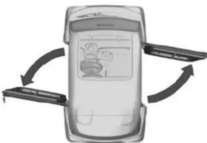
Caution
Do not open the door when moving.
Unlock / lock
To unlock / lock the vehicle, insert the key into the lock and turn it clockwise / anticlockwise.

Note
The vehicle can only be unlocked or locked from the outside.
Opening
After unlocking, press the door lock to open the door.

To open the door from the inside, pull the opening strap.
Closing

To close the doors from the inside, pull the closing strap of the respective door.
Mirrors
The exterior mirrors are adjusted and folded manually.
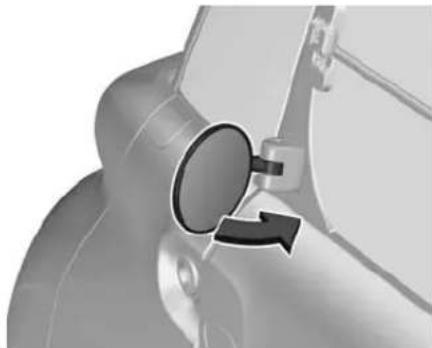
Move the exterior mirrors in several directions in order to obtain the best visibility.

Windows
The windows consist of a fixed upper part and a moveable lower part.
Opening
| Caution |
| When opening the window, ensure that it is properly locked before driving off, as it may unlock or lower while driving. |
At first, press the locking handle to release the window (1).

Then, lift the window as far as possible to keep it fully open (2).
Closing
⚠ Waining
Take care when closing the windows. Risk of injury.
To unlock the window, pull the window from the outside, then lower it until it locks in place.
Press against the window to check if it is locked.
Seat adjustment

Note
Only the driver's seat is adjustable.
Pull handle, slide seat, release handle. Try to move the seat back and forth to ensure that the seat is locked in place.
Seat belts
The seat belts are locked during heavy acceleration or deceleration of the vehicle, holding the occupants in the seat position. Therefore the risk of injury is considerably reduced.
⚠ Warning
Fasten seat belt before each trip. In the event of an accident, people not wearing seat belts endanger their fellow occupants and themselves.
Seat belts are designed to be used by only one person at a time.
Periodically check all parts of the seat belt system for damage, soiling and proper functionality.
Have damaged components replaced. After an accident, have the seat belts replaced by a workshop.
Fasten

Withdraw the seat belt from the retractor, guide it untwisted across the body and insert the latch plate into the buckle. Make sure the seat belt lies across the shoulder and fits tightly to the body while driving.

Loose or bulky clothing prevents the seat belt from fitting snugly. Do not place objects such as handbags or mobile phones between the seat belt and your body.
⚠ Warning
The seat belt must not rest against hard or fragile objects in the pockets of your clothing.
Unfasten

To release seat belt, press red button on seat belt buckle and guide the seat belt back.
Using seat belts while pregnant

⚠ Warning
The lap belt must be positioned as low as possible across the pelvis to prevent pressure on the abdomen.
Child restraint systems
⚠️ Danger
Make sure that children below sufficient size and weight are protected using a suitable child restraint system. Never place a child on the lap.
When a child restraint system is being used, pay attention to the following usage and installation instructions and also those supplied with the child restraint system. The given restrictions in the table refer to a test body, which is the maximum envelope of all existing child restraint systems.
Always comply with local or national regulations. In some countries, the use of child restraint systems is forbidden on certain seats.
Selecting the right system
Children should travel facing rearwards in the vehicle as long as possible. This makes sure that the child's backbone, which is still very weak, is under less strain in the event of an accident. Do not use forward facing child restraint system at all seats when child's weight is below 13 kg.
Suitable are child restraint systems that comply with valid UN ECE regulations. Check local laws and regulations for mandatory use of child restraint systems.
Ensure that the child restraint system to be installed is compatible with the vehicle type.
Follow the child restraint system manufacturer's instructions to install the corresponding child restraint system in the vehicle.
When the child restraint system is not in use, secure the seat with a seat belt or remove it from the vehicle.
Note
Do not affix anything on the child restraint systems and do not cover them with any other materials.
A child restraint system which has been subjected to stress in an accident must be replaced.
Child restraint installation locations
In accordance with European regulations, this table indicates the options for installing child restraint systems secured using the seat belt and universally approved in relation to the weight of the child.
| Child restraint system categories | Weight of the child / indicative age | |||
| Under 13 kg (groups 0 1 ) and 0+): Up to about 1 year old | From 9 to 18 kg (group 1): From about 1 to 3 years old | From 15 to 25 kg (group 2): From about 3 to 6 years old | From 22 to 36 kg (group 3): From about 6 to 10 years old | |
Universal belted child restraint U UF UF UF system 2)
1) Group 0: birth to 10 kg. Carrycots and infant carriers cannot be installed on the front passenger seat.
2) Universal child seat: child seat that can be installed in all vehicles using the seat belt.
U : Seat position suitable for installing a child restraint system secured using the seat belt and universally approved for rearward facing and / or forward facing use.
UF : Seat position suitable for installing a child restraint system secured using the seat belt and universally approved for forward facing use.
Instrument panel overview

1 Window locking handle ..... 3
2 Closing strap 2
3 Turn lights 16
Windscreen wiper and washer .... 11
Horn .... 11
4 Opening strap 2
5 Driver Information Centre ..... 13
6 Ignition switch 17
7 USB port 12
8 Electric drive unit 18
9 Heating and ventilation system .... 16
Hazard warning flashers .... 16
10 Parking brake 19
Storage compartments
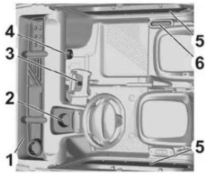
1 : Front storage compartment
2 : Driver's storage compartment / housing for Bluetooth speaker
3: Mobile device holder
4 : Hook for handbags
5 : Door panel storage compartments
6 : Passenger storage compartment
Modular load space
The modular load space is a multifunctional load compartment next to the driver's seat with a movable shelf at the top and a foldable shelf in the middle.
Additionally, it includes a closed storage compartment for small objects and a document holder.
Movable shelf
⚠ Warning
Do not drive with bulky objects on the movable shelf. Risk of falling objects and poor visibility.
The movable shelf is limited to a maximum of 40 kg.
The movable shelf can be folded up at both long sides.
⚠ Warning
Do not drive with the movable shelf folded up. Risk of dropping the movable shelf and poor visibility.

To remove the movable shelf, pull it upwards.

After removing, the movable shelf can be stored vertically next to the driver's seat.
Foldable shelf
Flat objects with a length of up to 1.2 m can be stored on the foldable shelf.
Secure the load in the middle of the foldable shelf with appropriate fasteners.

To increase the size of the load space, the foldable shelf can be folded up.
Closed storage compartment

To open the cover, press the button.
Document holder

Documents can be stored in the document holder on the movable shelf.
Horn

Press the button.
Windscreen wiper and washer
Windscreen wiper
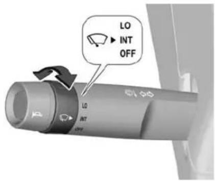
LO : continuous wiping
INT : interval wiping
OFF: off
Do not use if the windscreen is frozen.
Windscreen washer

Pull lever. Washer fluid is sprayed onto the windscreen and the wiper wipes a few times.
Washer fluid ➔ 23.
Power outlets

The USB port can be used to charge a portable device.
Driver Information Centre
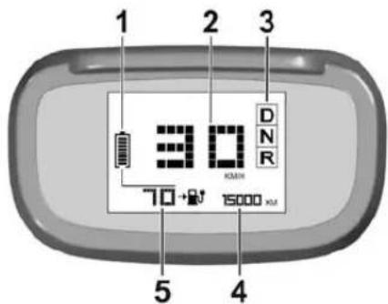
1 charge level of the traction battery
2 speedometer
3 selected drive mode
4 odometer
5 driving range or remaining charging time
The connectivity box attached to the on-board diagnostic connector (OBD-II) underneath the steering wheel sends vehicle data via Bluetooth. This data can then be displayed and analysed e.g. on a smartphone.

The overview table indicates what to do, when a control indicator illuminates or flashes.
Some control indicators will be accompanied by a warning chime.
Warning lights, gauges and indicators
| ⚠️ | STOP The vehicle must be stopped. A serious fault has been detected. Switch the ignition off and seek the assistance of a workshop. |
| (P) | Parking brake The parking brake is applied or not properly released. |
| (P)←→ | Parking brake The charging cable is connected and the parking brake is released. Charging or starting the vehicle is not possible. Apply the parking brake or disconnect the charging cable. |
| (!) | Braking The vehicle must be stopped. The brake fluid level has dropped significantly. Switch the ignition off, check for the presence of a leak and seek the assistance of a workshop. |
| Service One or more major faults have been detected. Seek the assistance of a workshop. | |
| Traction battery The traction battery has reached the first alert threshold. Charge the vehicle as soon as possible. | |
| Traction battery The traction battery has reached the second alert threshold. The vehicle's power decreases rapidly. The vehicle must be charged. | |
| Limited power A drop in performance in the drive train due to a low temperature of the traction battery. | |
| Traction battery The traction battery's temperature is too high. Seek the assistance of a workshop. | |
| ◀/→Turn lights The left or right turn lights are activated. | |
| ◀→ | Hazard warning flashers The hazard warning flashers are activated. |
Brake pedal Insufficient pressure or no pressure detected on the brake pedal for changing the direction of travel. Depress the brake pedal to select or change the direction of travel.
READY Vehicle switched on The light remains on and will extinguish when the vehicle is switched off and the passengers have left the vehicle.
- Charging cable connected The charging cable is connected to an electrical outlet.
Automatic light control
When the ignition is switched on, all the lights come on (sidelights, low beam and number plate light).
When the ignition is switched off, all the lights go out.
Hazard warning flashers

Operated by pressing △.
Turn lights

up : right turn lights down : left turn lights
A resistance point can be felt when moving the indicator lever.
Constant flashing is activated when the indicator lever is being moved beyond the resistance point. It is deactivated when the indicator lever is manually moved back to its neutral position.
To activate three flashes, tap the indicator lever briefly without passing the resistance point.
Heating and ventilation system

To activate or deactivate heating / demisting, press 🎩.
The demisting system reduces misting on the windscreen. If the side windows are misted up, wipe them with a clean, soft cloth.
The demisting of the windscreen can take up to 15 minutes or more.

To activate or deactivate ventilation, press ⌘.
Driving on wet roads
Caution
Do not drive on flooded roads as this could seriously damage your vehicle's motor and electrical system.
If driving on a flooded road is not avoidable:
- Check that the depth of water does not exceed 10 cm, taking account of waves that might be generated by other vehicles.
- Drive as slowly as possible without stalling. In all cases, do not exceed 10 km/h.
- Do not stop and do not switch off the motor.
When leaving the flooded road, as soon as safety conditions allow, make several light brake applications to dry the brake discs and pads. If in any doubt about the conditions of the vehicle, consult a dealer or qualified workshop.
Starting the engine

- Insert the key and turn the key to position 2 to switch on the ignition. When the ignition is switched on, the Driver Information Centre illuminates, all lights come on and the steering column is unlocked.
- Depress the brake pedal. Do not depress the accelerator pedal.
- Turn the key to position 3. N is engaged and READY illuminates in the Driver Information Centre.

If a drive position is selected without any pressure on the pedals for five seconds, a warning chime will sound.
Press D or R on the drive selector, then accelerate or brake.
Note
In order to protect the drive chain, a slight decrease in performance may be observed at low temperatures or during prolonged use of maximum power.
Switching off
- Depress the brake pedal.
-
Apply the parking brake.
-
Turn the key to position 1.
-
Release the brake pedal.
A few seconds after the ignition is switched off, the Driver Information Centre goes off, all the lights go out and the steering column is locked automatically.
Electric drive unit
The vehicle uses an electric drive unit with a 1-gear transmission.
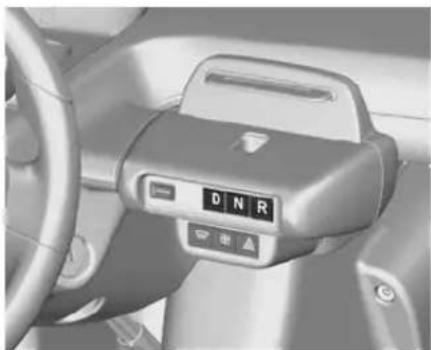
D: drive mode
N : neutral
R : reverse gear, engage only when the vehicle is stationary
Drive mode D
To shift into D, the vehicle must be at standstill and the brake pedal has to be depressed.
Caution
If the vehicle seems to accelerate slowly or not respond when you try to go faster, do not continue your journey. The electric drive unit could be damaged. Consult a workshop as soon as possible.
Neutral N
In this mode, the propulsion system does not transfer torque to the wheels.
Reverse gear R
To shift into and out of R, the vehicle must be at standstill and the brake pedal has to be depressed.
Caution
Shifting into R while the vehicle is moving forward could damage the electric drive unit. Only shift into R after the vehicle has been stopped.
Parking brake
⚠ Warning
Before leaving the vehicle, check the parking brake status. The control indicator (P) must illuminate constantly.

⚠ Warning
Always apply the parking brake firmly without operating the release button, and apply as firmly as possible on a downhill or uphill slope.
When parking on a slope, turn the front wheels towards the kerb.
To release the parking brake, pull the lever up slightly, press the release button and fully lower the lever.
To reduce the operating forces of the parking brake, depress the foot brake at the same time.
Charging
The traction battery stores the energy needed to operate the electric motor and the vehicle's electrical cabin components. It will be discharged during use and must therefore be regularly charged. There is no need to wait for the traction battery to fall to its reserve level before recharging.
The driving range can vary depending on the use of the electrical cabin components, the driving style, the route, and the age of its components.
Under standard conditions, full charging takes four hours and 20 minutes.
The charging time can deviate depending on the temperature and the age of the traction battery, the number of charging cycles carried out, and the version of the traction battery.
When the temperature of the traction battery is below 5 °C, the charging process could take up to six hours.
Caution
Charging is not possible if the temperature of the traction battery is below -5 °C.
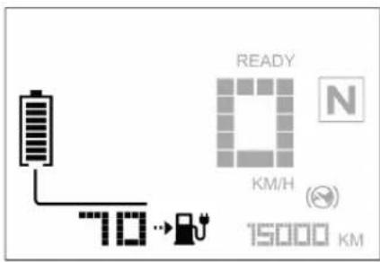
The charge level of the traction battery and the remaining driving range will be displayed in the Driver Information Centre.

Before charging, park the vehicle as close as possible to a domestic electrical outlet, apply the parking brake and switch off the engine.
Caution
Do not use an extension cable, a multi-plug connector, a conversion adaptor or a damaged power outlet.

The charging cable is permanently attached to the vehicle. It is stored inside the door frame of the right door.
Note
Depending on country version the electric plug differs.
To charge the traction battery, unfurl the charging cable fully.

Close the right door and ensure that the charging cable passes through the guide hole in the door frame into the handle recess.
Caution
The electric plug is water-protected until IPX6. Do not use the electric plug after a submersion in water and contact a workshop.
Connect the charging cable to a domestic electrical outlet.
Version with leakage protection plug
- To start charging, press RESET The LED will illuminate red to indicate the charging process.
• To interrupt the charging process, press TEST. The LED will extinguish.
Start and interrupt the charging process two or three times to check whether the leakage protection plug is working correctly.
The charging procedure stops automatically when the traction battery is fully charged.
The charging process can be interrupted at any time.

The remaining charging time is displayed in the Driver Information Centre. When the charging process is completed, 0:00 will be displayed in the Driver Information Centre or the Driver Information Centre will be switched off.
After charging, disconnect the charging cable, open the right door and store the cable in its housing.
Vehicle storage
Caution
To immobilise the vehicle for more than a month, park the vehicle at a weatherproof location where the temperature is between 0 °C and 40 °C.
The charging level of the traction battery must be around 50%.
Disconnect the connectivity box. Remove the F7 fuse in fuse box 1.
Disconnect the vehicle battery.
Vehicle battery ➔ 24.
Fuses 28.
Performing work
△WWaining
Before doing any works, switch off the ignition, apply the parking brake, check that the Driver Information Centre is off and that the charging cable is not connected.
Removing the front or rear bumper
Before the rear bumper can be removed, the number plate light needs to be removed as described below.
- Pass the number plate light's suspended wiring loom behind the bumper.

- Remove the two lower fixing screws from the frame.
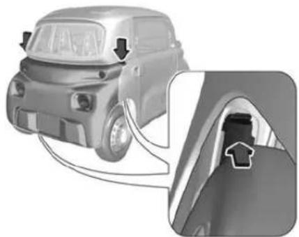
- Remove the two upper access flaps from the wings.
Pass an arm under a wing and lift it up.

- Remove the two upper side fixing screws from the flaps.

- Remove the two lower side fixing screws from the wheel arches.
- Pull the bumper horizontally for about 10 cm until the attachment points come away.

- Disconnect the turn light wiring looms.
Refitting the front or rear bumper
- Bring the bumper close to the frame.
-
Connect the turn light wiring looms.
-
Place the bumper in position and push the bumper horizontally until the attachment points clip into place.
- Screw the two upper side fixing screws into the flaps.
- Screw the two lower side fixing screws into the wheel arches.
- Screw the two lower fixing screws into the frame.
- Clip the two upper access flaps to the wings.
When the rear bumper is refitted, replace the number plate light.
Removing and refitting the number plate light
- Lie down behind the vehicle in the middle of the rear bumper.
- Pass an arm behind the bumper to reach the light above the foam shock absorber.
- Pinch the fixing clip holding the light.
-
Push the light down while holding the fixing clip.
-
Disconnect the light from its wiring loom.
- Leave the wiring loom dangling through the bumper.
To refit the number plate light, reconnect the light to the suspended wiring loom and replace the light into its housing by pressing it until it clips into place.
Washer fluid
The washer fluid tank is located behind the seats.

Turn both fixing screws a quarter turn and remove the access cover.

Remove the cap from the tank to top up.
Fill with clean water mixed with a suitable quantity of approved windscreen washer fluid which contains antifreeze.
Caution
Only washer fluid with a sufficient antifreeze concentration provides protection at low temperatures or a sudden drop in temperature.
Washer fluid ➔ 31.
Brake fluid
△Waining
Brake fluid is poisonous and corrosive. Avoid contact with eyes, skin, fabrics and painted surfaces.
To get access to the brake fluid tank, the front bumper needs to be removed ⇒ 22.
Caution
Before topping up, it is necessary to protect the electric motor in order to avoid any risks of brake fluid splashing onto it.

The brake fluid level must be between the MIN and MAX marks.
If fluid level is below MIN seek the assistance of a workshop.
Brake fluid ➔ 31.
Vehicle battery
The vehicle battery is maintenance-free provided that the driving profile allows sufficient charging of the battery. Avoid the use of unnecessary electrical consumers.

Batteries do not belong in household waste. They must be disposed of at an appropriate recycling collection point.
Laying up the vehicle for more than four weeks can lead to battery discharge. Disconnect the clamp from the negative terminal of the vehicle battery.
Ensure the ignition is switched off before connecting or disconnecting the vehicle battery.
Removing the vehicle battery
⚠ Warning
Before doing any works, switch off the ignition, apply the parking brake, check that the Driver
Information Centre is off and that the charging cable is not connected.
To get access to the vehicle battery, the rear bumper needs to be removed 22.

First, disconnect the negative terminal.
When the negative terminal is disconnected, disconnect the positive terminal.
Disconnect a terminal as follows:
- Unscrew and remove the screw (1) from the clamp (2).
- Remove the clamp (2) from the terminal.
⚠ Warning
Make sure that the disconnected clamps do not come into contact with the vehicle battery terminals.
When both terminals are disconnected, proceed as follows:
- Unscrew the fixing screws (3) on the vehicle battery's retainer brace (4).
- Remove the retainer brace (4) and the vehicle battery.
Refitting the vehicle battery
- Place the vehicle battery into its compartment.
- Replace the retainer brace (4) and its fixing screws (3).
Next, the terminals need to be reconnected. Reconnect the positive terminal first.
When the positive terminal is reconnected, reconnect the negative terminal.
Reconnect a terminal as follows:
- Insert the nut horizontally into the terminal's square housing.
- Place the clamp (2) on top of the terminal.
- Insert the screw (1) into the terminal and nut and screw tight.
Starting using another battery
If the vehicle battery is flat, the electric motor can be started using a backup battery (either external or from another vehicle) and jump leads or using a battery booster.
⚠ Waining
- Never start the electric motor by connecting a battery charger.
-
Never use a 24 V or higher battery booster.
-
Check beforehand that the backup battery has a nominal voltage of 12 V and a capacity at least equal to that of the discharged battery.
- The two vehicles must not be in contact with each other.
- Disconnect or turn off all electrical devices in both vehicles (portable devices, wipers, lights, etc.).
- Do not disconnect the positive terminal while the electric motor is switched on.

- Connect the red lead to the positive terminal of the booster battery (1).
- Connect the other end of the red lead to the positive terminal of the discharged battery (2).
- Connect the black lead to the negative terminal of the booster battery (3).
- Connect the other end of the black lead to the negative terminal of the discharged battery (4).
- When connected to an assisting vehicle, start the engine on the assisting vehicle and leave it running for a few minutes.
- Turn the ignition key to start the disabled vehicle. The traction battery takes over the supply to the 12 V circuit.
- Wait for the assisting vehicle to return to idle.
- Disconnect the jump leads in reverse order.
- Leave the vehicle switched on for at least 30 minutes to allow the
traction battery to recharge the vehicle battery.
If the battery charge level in the traction battery is too low, connect the vehicle's charging cable.
Charging the vehicle battery using a battery charger
For optimum service life of the vehicle battery, it is essential to maintain an adequate level of charge.
In some circumstances, it may be necessary to charge the vehicle battery:
- When using the vehicle mainly for short journeys.
- If the vehicle is to be taken off the road for several weeks.
Warning
- Only use a charger compatible with lead-acid batteries and with a nominal voltage of 12 V.
- Follow the instructions provided by the manufacturer of the charger.
- Never reverse polarities.
- Disconnect the vehicle battery from the vehicle.
• Make sure the vehicle's charging cable is not connected at the same time.
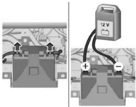
Before charging the vehicle battery using a battery charger, the vehicle battery needs to be disconnected from the vehicle.
To charge the vehicle battery using a battery charger, proceed as follows:
- Switch the charger off before connecting the cables to the vehicle battery to avoid any dangerous sparks.
- Ensure that the charger cables are in good condition.
- Connect the red cable to the positive terminal on the vehicle battery.
- Connect the black cable to the negative terminal on the vehicle battery.
At the end of the charging operation, switch the charger off before disconnecting the cables from the vehicle battery.
Wiper blade replacement
Caution
• Take care not to hold the arms at the jet locations.
- Do not release them while moving them. Risk of damaging the windscreen.

- Grasp the wiper blade by its rigid part and pull it towards you as far as it will go.
-
While keeping the wiper arm raised, unclip the worn blade (1) and remove it (2).
-
While keeping the wiper arm raised, install the new blade and clip it into place.
- Lower the arm carefully and support it until it reaches the windscreen.
Bulb replacement
All lights are designed as LEDs and cannot be changed.
Have lights repaired by a workshop in case of failure.
Fuses
Data on the replacement fuse must match the data on the defective fuse.
Before replacing a fuse, turn off the respective switch and the ignition.
A blown fuse can be recognised by its melted wire.
Caution
Do not replace the fuse until the cause of the fault has been remedied.
The fuse boxes are located behind the seats.

Turn both fixing screws a quarter turn and remove the access cover.
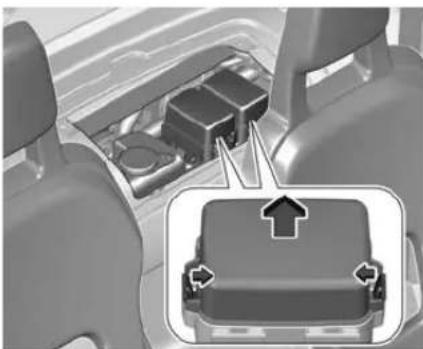
Unclip the access covers of the fuse boxes.
Pull out the blown fuse and replace it.
Fuse box 1

No. Circuit
1 Brake switch
2 Main computer
3 Fan
4 Instrument panel
5 Battery computer
No. Circuit
6 Horn
7 Battery drive train / DC/DC converter
Fuse box 2

No. Circuit
1 Steering mounted control
2 Main computer
3 Screenwash pump
4 -
No. Circuit
5 Instrument panel control indicators
6 -
7 Motor computer
8 Brake switch
9 USB power outlet / lighting for ventilation / heating / demisting buttons / drive selector
10 -
11 Diagnostic socket
12 Wiper motor
13 Rear left wheel speed sensor
14 Sidelights front left and rear right / number plate light
15 Sidelights rear left and front right
16 Right-hand dipped beam head-light
No. Circuit
17 Left-hand dipped beam head-light
18 Wiper motor
Tyre pressure
The tyre inflation pressures are indicated on a label located on the base of the driver's seat.
Incorrect tyre pressures will impair safety, vehicle handling, comfort and will increase tyre wear.
For the tyres approved for your vehicle, refer to the Certificate of Conformity provided with your vehicle or other national registration documents.
The driver is responsible for correct adjustment of tyre pressure.
Temperature dependency
The tyre pressure depends on the temperature of the tyre. During driving, tyre temperature and pressure increase. Tyre pressure
values provided on the tyre information label are valid for cold tyres, which means at 20 °C.
The pressure increases by nearly 10 kPa for a 10 °C temperature increase. This must be considered when warm tyres are checked.
Wheel changing
The vehicle is not equipped with on-board tools, such as a jack or wheel brace.
In the event of a flat tyre, seek the assistance of a workshop.
To have winter tyres fitted or the wheels changed, consult a dealer or qualified workshop.
Caution
Do not use tyre chains.
Towing the vehicle
Transport the broken-down vehicle only on a platform.

Use the towing eye only for recovering the vehicle or to secure it for transportation.
Exterior care
Caution
Do not use an automatic car wash or high-pressure cleaning devices.
Lock the doors and windows before cleaning the vehicle.
Do not wash the vehicle in full sunhsine or in extremely cold conditions.
Use a garden hose or a sponge and soapy water to clean the vehicle. Only use pH-neutral soap.
Service information
In order to ensure economical and safe vehicle operation and to maintain the value of your vehicle, it is of vital importance that all maintenance work is carried out at the proper intervals as specified.
The detailed, up-to-date service schedule for your vehicle is available at the workshop.
The service interval is two years or 20 000 km, whichever comes first.
Recommended fluids and lubricants
Only use products that meet the recommended specifications.
⚠ Warning
Operating materials are hazardous and could be poisonous. Handle with care. Pay attention to information given on the containers.
Washer fluid
Use only washer fluid approved for the vehicle to prevent damage of wiper blades, paintwork, plastic and rubber parts. Consult a workshop.
Brake fluid
Over time, brake fluid absorbs moisture which will reduce braking effectiveness. The brake fluid should therefore be replaced at the specified interval.
Use only DOT4 brake fluid from a sealed container. Consult a workshop.
Vehicle identification number

The Vehicle Identification Number is embossed in the roof inside the vehicle.
Identification plate
The identification label is located on the base of the right side.

1 manufacturer / type approval number
2 vehicle identification number
3 noise level / rated speed
4 maximum power / maximum speed / gross vehicle weight
Declaration of conformity
For the declaration of conformity and other customer information, see online.
Vehicle data
| Unladen vehicle weight without driver [kg] 483 / 487 |
| Gross vehicle weight [kg] 700 |
| Nominal power [kW] 6 |
| Traction battery capacity [kWh] 5.4 |
| AC charging 230 V (single-phase) / 8 A |
| Charging cable length [m] 3 |
| Driving range [km] 75 |
| Vehicle length [mm] 2410 |
| Vehicle width with two exterior mirrors folded [mm] 1388 |
| Vehicle width with two exterior mirrors [mm] 1541 |
| Vehicle height [mm] 1525 |
| Maximum speed [km/h] 45 |

www.opel.com
Copyright by Opel Automobile GmbH, Rüsselsheim, Germany.
The information contained in this publication is effective as of the date indicated below. Opel Automobile GmbH reserves the right to make changes to the technical specifications, features and design of the vehicles relative to the information in this publication as well as changes to the publication itself.
Edition: October 2023, Opel Automobile GmbH, Rüsselsheim.
Printed on chlorine-free bleached paper.
OROCKAQ2310en




- INTRODUCTION
- DANGER, WARNINGS AND CAUTIONS
- ⚠️D DANGER
- ⚠ WARNING
- CAUTION
- SYMBOLS
- KEYS
- FRONT DOORS
- UNLOCK / LOCK
- NOTE
- OPENING
- MIRRORS
- WINDOWS
- CLOSING
- ⚠ WAINING
- SEAT ADJUSTMENT
- SEAT BELTS
- USING SEAT BELTS WHILE PREGNANT
- CHILD RESTRAINT SYSTEMS
- ⚠️ DANGER
- SELECTING THE RIGHT SYSTEM
- CHILD RESTRAINT INSTALLATION LOCATIONS
- STORAGE COMPARTMENTS
- MODULAR LOAD SPACE
- MOVABLE SHELF
- FOLDABLE SHELF
- WINDSCREEN WIPER AND WASHER
- POWER OUTLETS
- DRIVER INFORMATION CENTRE
- AUTOMATIC LIGHT CONTROL
- DRIVING ON WET ROADS
- STARTING THE ENGINE
- SWITCHING OFF
- ELECTRIC DRIVE UNIT
- DRIVE MODE D
- NEUTRAL N
- REVERSE GEAR R
- PARKING BRAKE
- CHARGING
- VERSION WITH LEAKAGE PROTECTION PLUG
- VEHICLE STORAGE
- PERFORMING WORK
- △WWAINING
- REMOVING THE FRONT OR REAR BUMPER
- REFITTING THE FRONT OR REAR BUMPER
- REMOVING AND REFITTING THE NUMBER PLATE LIGHT
- WASHER FLUID
- BRAKE FLUID
- △WAINING
- VEHICLE BATTERY
- REMOVING THE VEHICLE BATTERY
- REFITTING THE VEHICLE BATTERY
- STARTING USING ANOTHER BATTERY
- CHARGING THE VEHICLE BATTERY USING A BATTERY CHARGER
- WARNING
- WIPER BLADE REPLACEMENT
- BULB REPLACEMENT
- FUSES
- NO. CIRCUIT
- TYRE PRESSURE
- TEMPERATURE DEPENDENCY
- WHEEL CHANGING
- TOWING THE VEHICLE
- EXTERIOR CARE
- SERVICE INFORMATION
- RECOMMENDED FLUIDS AND LUBRICANTS
- VEHICLE IDENTIFICATION NUMBER
- IDENTIFICATION PLATE
- DECLARATION OF CONFORMITY
Brand : OPEL
Model : Rocks (2023)
Category : Car