
Viva (2016) - Car OPEL - Free user manual and instructions
Find the device manual for free Viva (2016) OPEL in PDF.


| Product Type | Car |
| Brand | Opel |
| Model | Viva (2016) |
| Category | Subcompact City Car |
| Dimensions (L x W x H) | 3675 mm x 1660 mm x 1490 mm |
| Wheelbase | 2385 mm |
| Curb Weight | 939 kg (approx.) |
| Fuel Type | Petrol (Gasoline) |
| Engine Displacement | 1.0 L (999 cc) 3-cylinder |
| Transmission | 5-speed manual |
| Seating Capacity | 5 |
| Fuel Tank Capacity | 32 L |
| Fuel Consumption (combined) | 4.3 L/100 km (approx.) |
| CO2 Emissions | 99 g/km (approx.) |
| Safety Systems | ABS, ESC, Front Airbags |
| Maintenance Interval | Oil change every 15,000 km or 1 year |
| Cleaning Instructions | Use mild soap for exterior; vacuum interior regularly |
| Spare Parts Availability | Through Opel dealerships and authorized service centers |
| Repairability | Modular design; many components replaceable individually |
| User Manual Language | English |
| Number of Pages | 197 |
Frequently Asked Questions - Viva (2016) OPEL
User questions about Viva (2016) OPEL
0 question about this device. Answer the ones you know or ask your own.
Ask a new question about this device
Download the instructions for your Car in PDF format for free! Find your manual Viva (2016) - OPEL and take your electronic device back in hand. On this page are published all the documents necessary for the use of your device. Viva (2016) by OPEL.
USER MANUAL Viva (2016) OPEL
Contents
Introduction 2
In brief 6
Keys, doors and windows ..... 19
Seats, restraints 31
Storage 49
Instruments and controls ..... 56
Lighting 88
Climate control 94
Driving and operating 103
Vehicle care 131
Service and maintenance ..... 169
Technical data 172
Customer information 183
Index 190
2 Introduction
Introduction
| Fuel | Designation | |
| Engine oil | Grade | |
| Viscosity |
| Tyre pressure | Tyre size |
| Summer tyres | |
| Winter tyres |
| Weights |
| Gross vehicle weight rating |
| - Kerb weight, basic model |
| = Loading |
| Front | Rear |
Introduction 3
Vehicle specific data
Please enter your vehicle's data on the previous page to keep it easily accessible. This information is available in the sections "Service and maintenance" and "Technical data" as well as on the identification plate.
Introduction
Your vehicle is a designed combination of advanced technology, safety, environmental friendliness and economy.
This Owner's Manual provides you with all the necessary information to enable you to drive your vehicle safely and efficiently.
Make sure your passengers are aware of the possible risk of accident and injury which may result from improper use of the vehicle.
You must always comply with the specific laws and regulations of the country that you are in. These laws may differ from the information in this Owner's Manual.
Disregarding the description given in this manual may affect your warranty.
When this Owner's Manual refers to a workshop visit, we recommend your Vauxhall Authorised Repairer.
For gas vehicles, we recommend a Vauxhall Authorised Repairer licensed to service gas vehicles.
All Vauxhall Authorised Repairers provide first-class service at reasonable prices. Experienced mechanics trained by Vauxhall work according to specific Vauxhall instructions.
The customer literature pack should always be kept ready to hand in the vehicle.
Using this manual
- This manual describes all options and features available for this model. Certain descriptions, including those for display and menu functions, may not apply to your vehicle due to model variant, country specifications, special equipment or accessories.
- The "In brief" section will give you an initial overview.
- The table of contents at the beginning of this manual and within each section shows where the information is located.
- The index will enable you to search for specific information.
- This Owner's Manual depicts left-hand drive vehicles. Operation is similar for right-hand drive vehicles.
- The Owner's Manual uses the engine identifier code. The corresponding sales designation can be found in the section "Technical data".
- Directional data, e.g. left or right, or front or back, always relate to the direction of travel.
- Displays may not support your specific language.
- Display messages and interior labelling are written in bold letters.
4 Introduction
Danger, Warnings and Cautions

Danger
Text marked △Danger provides information on risk of fatal injury. Disregarding this information may endanger life.

Warning
Text marked △Warning provides information on risk of accident or injury. Disregarding this information may lead to injury.
Caution
Text marked Caution provides information on possible damage to the vehicle. Disregarding this information may lead to vehicle damage.
Symbols
Page references are indicated with ➔. ➔ means "see page".
Page references and index entries refer to the indented headings given in the section table of content.
Chronological order to select menu entries in the vehicle personalisation is indicated with ♦.
Thank you for choosing a Vauxhall.
We wish you many hours of pleasurable driving.
Your Vauxhall Team
6 In brief
In brief
Initial drive information
Vehicle unlocking
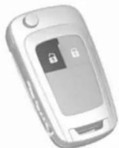
Press 🔒 to unlock the doors and load compartment. Open the doors by pulling the handles.

To open the tailgate, push the switch on the underside of the brand emblem.
Radio remote control ⇒ 20, Central locking system ⇒ 21, Load compartment ⇒ 24.
Seat adjustment
Longitudinal adjustment

Pull handle, slide seat, release handle. Try to move the seat back and forth to ensure that the seat is locked in place.
Seat position 32, Seat adjustment 33.
Backrest inclination
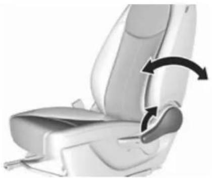
Pull lever, adjust inclination and release lever. Allow the seat to engage audibly.
Seat position ⇒ 32, Seat adjustment ⇒ 33.
Seat height

Lever pumping motion
up : seat higher
down : seat lower
Seat position ⇒ 32, Seat adjustment ⇒ 33.
8 In brief
Head restraint adjustment

Press release button, adjust height and engage.
Head restraints ➔ 31.
Seat belt

Pull out the seat belt and engage in belt buckle. The seat belt must not be twisted and must fit close against the body. The backrest must not be tilted back too far (maximum approx. 25°).
To release belt, press red button on belt buckle.
Seat position ⇒ 32, Seat belts
35, Airbag system 37.
Mirror adjustment
Interior mirror
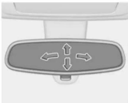
To adjust the mirror, move the mirror housing in the desired direction.
Manual anti-dazzle interior mirror 27.
Exterior mirrors

Select the relevant exterior mirror and adjust it.
Exterior mirrors ⇒ 26, Electric adjustment ⇒ 26, Folding exterior mirrors ⇒ 26.
Heated exterior mirrors 26.
Steering wheel adjustment

Unlock the lever, adjust the steering wheel, then engage the lever and ensure it is fully locked.
Do not adjust the steering wheel unless the vehicle is stationary and the steering wheel lock has been released.
Airbag system 37, Ignition positions 104.
10 In brief
Instrument panel overview
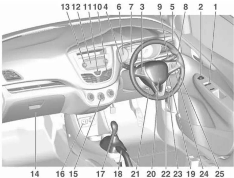
1 Power windows 28
Central locking system ..... 21
2 Exterior mirrors 26
3 Cruise control .... 119 Speed limiter .... 121 Heated steering wheel .... 57
4 Turn and lane-change signals, headlight flash, low beam and high beam ..... 90 Exit lighting ..... 93 Parking lights ..... 91
5 Side air vents 100
6 Instruments 61
7 Driver Information Centre ..... 73
8 Steering wheel controls ..... 57
9 Windscreen wiper, windscreen washer system, rear window wiper, rear window washer system .... 58
10 Centre air vents 100
11 Hazard warning flashers ..... 89
12 Info-Display 78
13 Anti-theft alarm system status LED 25
14 Infotainment system 15 Glovebox .... 49 16 Climate control system .... 94
17 AUX input, USB input 18 Selector lever, manual transmission .... 110 Selector lever, manual transmission automated ..... 111
19 Seat heating .... 34 20 Parking brake .... 115
21 Ignition switch with steering wheel lock .... 104
22 Horn 58 Driver airbag 40
23 Bonnet release lever ..... 133
24 Steering wheel adjustment .. 5 7
25 Fuse box 147
26 Traction Control system .... 116 City mode .... 118 Stop-start system .... 106 Fuel selector .... 63 Lane departure warning .... 123
Electronic Stability Control . 117
27 Light switch 88
Headlight range adjustment .... 89 Front fog light .... 90 Rear fog light .... 90
Brightness of instrument panel illumination 91
12 In brief
Exterior lighting
Light switch

Turn light switch:
0 : lights off
: sidelights
ID : headlights
Fog lights
Press button in light switch:
D : front fog lights
0‡ : rear fog light
Headlight flash, high beam and low beam

headlight flash : pull lever
high beam : push lever
low beam : push or pull lever
High beam 88, Headlight flash 88.
Turn and lane-change signals

lever up : right turn signal
lever down : left turn signal
Turn and lane-change signals
90, Parking lights 91.
Hazard warning flashers
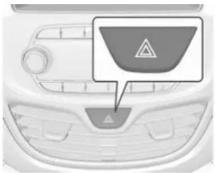
Operated by pressing ⚠. Hazard warning flashers ➡ 89.
Horn

Press ▶.
Washer and wiper systems
Windscreen wiper

HI : fast
LO : slow
: interval wiping
OFF : off
For single wipe when the wiper is off, press lever down to position 🔒.
Windscreen wiper 58.
14 In brief
Windscreen washer

Pull lever.
Windscreen washer system 58, Washer fluid 135, Wiper blade replacement 138.
Rear window wiper

Press the rocker switch to activate the rear window wiper:
upper switch : continuous operation
lower switch : intermittent operation
middle position : off
Rear window washer
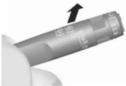
Push lever.
Washer fluid is sprayed on the rear window and the wiper wipes a few times.
Rear window wiper/washer ➔ 59.
Climate control
Heated rear window

The heating is operated by pressing ☐.
Heated rear window ➔ 29.
Heated exterior mirrors
Pressing ☐ also activates the heated exterior mirrors.
Heated exterior mirrors ⇒ 26.
Demisting and defrosting the windows

- Press
- Set temperature control to warmest level.
- Set fan speed to highest level.
- Switch on heated rear window 📄.
- Open side air vents as required and direct them towards the door windows.
Climate control system ↩ 94.
Transmission
Manual transmission

Reverse: with the vehicle stationary, depress clutch pedal and press the release button on the selector lever and engage the gear.
If the gear does not engage, set the lever to neutral, release the clutch pedal and depress again; then repeat gear selection.
Manual transmission 110.
16 In brief
Manual transmission automated

R : reverse, engage only when vehicle is stationary
N : neutral
D : automatic mode
M : manual mode
+ : upshift in manual mode
— :downshift in manual mode
Manual transmission automated 111.
Starting off
Check before starting off
- Tyre pressure and condition ↗ 150, ↗ 182.
- Engine oil level and fluid levels ↗ 134.
- All windows, mirrors, exterior lighting and number plates are free from dirt, snow and ice and are operational.
- Proper position of mirrors, seats, and seat belts 26, 32, 36.
- Brake function at low speed, particularly if the brakes are wet.
Starting the engine

- Turn key to position 1.
- Move the steering wheel slightly to release the steering wheel lock.
- Manual transmission: operate clutch and brake pedal.
Manual transmission automated: operate brake pedal.
Automatic transmission: operate brake pedal and move selector lever to P or N. - Do not operate accelerator pedal.
- Turn key to position 3 and release.
Starting the engine 105.
Stop-start system

If the vehicle is at a low speed or at a standstill and certain conditions are fulfilled, activate an Autostop as follows:
Vehicles with manual transmission:
- Depress the clutch pedal.
- Set the lever to neutral.
- Release the clutch pedal.
An Autostop is indicated by the needle at the AUTOSTOP position in the tachometer.
To restart the engine, depress the clutch pedal again.
Vehicles with manual transmission automated:
If the vehicle is at a standstill with the brake pedal depressed, Autostop is activated automatically, indicated by the needle at the AUTOSTOP position in the tachometer.
Release the brake pedal or move selector lever out of D to restart the engine.
Stop-start system ↩ 106.
18 In brief
Parking

Warning
- Do not park the vehicle on an easily ignitable surface. The high temperature of the exhaust system could ignite the surface.
- Always apply the parking brake. Activate the manual parking brake without pressing the release button. Apply as firmly as possible on a downhill slope or uphill slope. Depress brake pedal at the same time to reduce operating force.
- Switch off the engine.
- If the vehicle is on a level surface or uphill slope, engage first gear before removing the ignition key. On an uphill slope, turn the front wheels away from the kerb.
If the vehicle is on a downhill slope, engage reverse gear before removing the ignition
key. Turn the front wheels towards the kerb.
- Close the windows and the sunroof.
- Remove the ignition key from the ignition switch. Turn the steering wheel until the steering wheel lock is felt to engage.
For vehicles with manual transmission automated, the key can only be removed from the ignition switch when the parking brake is applied.
- Lock the vehicle by pressing ⏻ on the radio remote control.
Activate the anti-theft alarm system ⇒ 25. - The engine cooling fans may run after the engine has been switched off 133.
Caution
After running at high engine speeds or with high engine loads, operate the engine briefly at a low load or run in neutral for approx. 30 seconds before switching off, in order to protect the turbocharger.
Keys, locks 19, Laying-up the vehicle for a long period of time 132.
Keys, doors and windows
Keys, locks 19
Keys 19
Radio remote control 20
Memorised settings 21
Central locking system 21
Child locks 23
Doors 24
Load compartment 24
Vehicle security 25
Anti-theft alarm system 25
Immobiliser 25
Exterior mirrors 26
Mirrors 26
Electric adjustment 26
Folding mirrors 26
Heated mirrors 26
Interior mirrors 27
Manual anti-dazzle 27
Windows 27
Windscreen 27
Manual windows 27
Power windows 28
Heated rear window 29
Sun visors 29
Roof 29
Sunroof 29
Keys, locks
Keys
Caution
Do not attach heavy or bulky items to the ignition key.
Replacement keys
The key number is specified in the Car Pass or on a detachable tag.
The key number must be quoted when ordering replacement keys, as it is a component of the immobiliser system.
Locks ↩ 166.
The code number of the adapter for the locking wheel bolts is specified on a card. It must be quoted when ordering a replacement adapter.
Wheel changing 159.
20 Keys, doors and windows
Lock cylinders
Designed to free-wheel if they are forcefully rotated without the correct key or if the correct key is not fully inserted. To reset, turn cylinder with the correct key until its slot is vertical, remove key and then re-insert it. If the cylinder still free-wheels, turn the key through 180° and repeat operation.
Key with foldaway key section

Press button to extend. To fold the key, first press the button.
Radio remote control

Used to operate:
• central locking system
• anti-theft alarm system
The radio remote control has a range of approx. 20 metres. It can be restricted by external influences. The hazard warning flashers confirm operation.
Handle with care, protect from moisture and high temperatures and avoid unnecessary operation.
Fault
If the central locking system cannot be operated with the radio remote control, it may be due to the following:
• The range is exceeded.
• The battery voltage is too low.
- Frequent, repeated operation of the radio remote control while not in range, which will require re-synchronisation.
• Overload of the central locking system by operating at frequent intervals, the power supply is interrupted for a short time.
• Interference from higher-power radio waves from other sources.
Unlocking ➔ 21.
Radio remote control battery replacement
Replace the battery as soon as the range reduces.

Batteries do not belong in household waste. They must be disposed of at an appropriate recycling collection point.
Key with foldaway key section
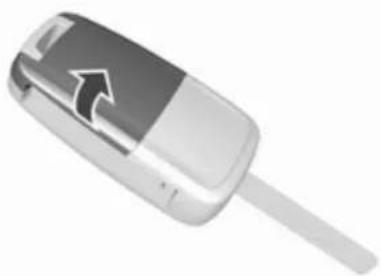
Extend the key and open the unit sideways. Replace the battery (battery type CR 2032), paying attention to the installation position. Close the unit and synchronise.
Radio remote control synchronisation
After replacing the battery, unlock the door with the key in the driver's door lock. The radio remote control will be synchronised when the ignition is switched on.
Memorised settings
Whenever the key is removed from the ignition switch, the following settings are automatically memorised by the key:
- lighting
- presets for Infotainment system
• central locking system - comfort settings
The saved settings are automatically used the next time the memorised key is inserted into the ignition switch and turned to position 1 ⇔ 104.
A precondition is that Personalization By Driver is activated in the personal settings of the Info-Display.
This must be set for each key used. Vehicle personalisation ➔ 82.
Central locking system
Unlocks and locks doors and load compartment.
Notice
In the event of an accident in which airbags or belt pretensioners are deployed, the vehicle is automatically unlocked.
Unlocking

Press 🔒.
22 Keys, doors and windows
Two settings are selectable in the Info-Display:
- To unlock only the driver's door, press 📋 once. To unlock all doors and load compartment, press 📋 twice.
- Press ☑ once to unlock all doors and load compartment.
The setting can be changed in the menu Settings in the Info-Display. Vehicle personalisation 82.
The setting can be saved for the key being used.
Memorised settings ➔ 21.
Locking
Close doors, load compartment and fuel filler flap.

Press 🔒.
If the driver's door is not closed properly, the central locking system will not work.
Central locking buttons
Locks or unlocks doors and the load compartment from inside the passenger compartment.

Press 🔒 to lock.
Press 🔒 to unlock.
Fault in radio remote control system
Unlocking
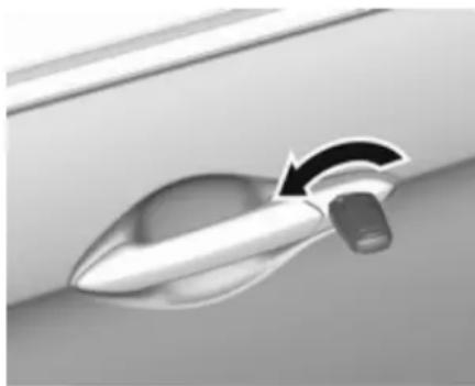
Manually unlock the driver's door by turning the key in the lock. Switch on the ignition and press the central locking button 🔒 to unlock the other doors and load compartment.
By switching on the ignition, the anti-theft alarm system is deactivated.
Locking
Close all doors. Open the driver's door and press the central locking button. The vehicle is locked.
Close the driver's door. Manually lock the driver's door by turning the key.
Fault in central locking system
Unlocking
Manually unlock the driver's door by turning the key in the lock. From the inside of the vehicle the doors can be unlocked by pulling up the lock button on the respective door. The load compartment cannot be unlocked.
Automatic door locking
If no door is opened or the position of ignition key is not located in position 1 or position 2 within three minutes after unlocking with the radio remote control, all the doors are locked and the anti-theft alarm system is activated automatically.
Child locks
⚠ Warning
Use the child locks whenever children are occupying the rear seats.
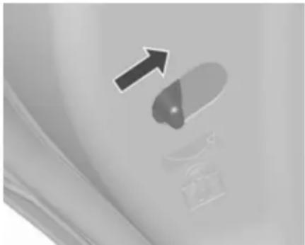
Move the pin in the rear door to the front. The door cannot be opened from inside.
24 Keys, doors and windows
Doors
Load compartment
Tailgate
Opening

To open the tailgate, push the switch on the underside of the brand emblem.
Closing

Use interior handle.
Do not press the touchpad switch whilst closing as this will unlock the tailgate again.
Central locking system ↩ 21.
General hints for operating tailgate
Danger
Do not drive with the tailgate open or ajar, e.g. when transporting bulky objects, since toxic exhaust
gases, which cannot be seen or smelled, could enter the vehicle. This can cause unconsciousness and even death.
Caution
Before opening the tailgate, check overhead obstructions, e.g. a garage door, to avoid damage to the tailgate. Always check the moving area above and behind the tailgate.
Notice
The installation of certain heavy accessories onto the tailgate may affect its ability to remain open.
Vehicle security
Anti-theft alarm system
The anti-theft alarm system is combined with the central locking system.
It monitors:
- doors, tailgate, bonnet
- ignition
Status LED

Status LED is integrated in the sensor on top of the instrument panel.
Status during the first 30 seconds of anti-theft alarm system activation:
LED illuminates : test, arming delay LED flashes : doors, tailgate or quickly bonnet not completely closed, or system fault
Seek the assistance of a workshop in the event of faults.
Deactivation
Unlocking the vehicle by pressing ⏻ deactivates anti-theft alarm system.
Alarm
When triggered, the alarm horn sounds and the hazard warning lights flash simultaneously. The number and duration of alarm signals are stipulated by legislation.
The alarm can be silenced by pressing any button on the radio remote control or by switching on the ignition.
The anti-theft alarm system can only be deactivated by pressing 📋 on the radio remote control or by switching on the ignition.
Vehicle messages ➔ 79.
Immobiliser
The system is part of the ignition switch and checks whether the vehicle is allowed to be started with the key being used.
The immobiliser is activated automatically after the key has been removed from the ignition switch.
If the control indicator ☑ flashes when the ignition is on, there is a fault in the system; the engine cannot be started. Switch off the ignition and repeat the start attempt.
If the control indicator continues flashing, attempt to start the engine using the spare key and seek the assistance of a workshop.
Notice
The immobiliser does not lock the doors. You should always lock the vehicle after leaving it.
Switch on the anti-theft alarm system ⇒ 21, ⇒ 25.
Control indicator 📄 → 72.
26 Keys, doors and windows
Exterior mirrors
Mirrors
The shape of the mirrors makes objects appear smaller, which will affect the ability to estimate distances.
Electric adjustment

Select the relevant exterior mirror by turning the control to left (L) or right (R). Then swivel the control to adjust the mirror.
In position 0 no mirror is selected.
Folding mirrors
For pedestrian safety, the exterior mirrors will swing out of their normal mounting position if they are struck with sufficient force. Reposition the mirror by applying slight pressure to the mirror housing.

Heated mirrors

Operated by pressing ☐.
Mirror heating works with the engine running.
It is switched off automatically after a short time.
Interior mirrors
Manual anti-dazzle

To reduce dazzle, adjust the lever on the underside of the mirror housing.
Windows
Windscreen
Windscreen stickers
Do not attach stickers, e.g. toll road stickers or similar, on the windscreen in the area of the interior mirror. Otherwise the detection zone of the sensor in the mirror housing could be restricted.
Windscreen replacement
Caution
If the vehicle has a front-looking camera sensor for the driver assistance systems, it is very important that any windscreen replacement is performed accurately according to Vauxhall specifications. Otherwise, these systems may not work properly and there is a risk of unexpected behaviour and/or messages from these systems.
Manual windows
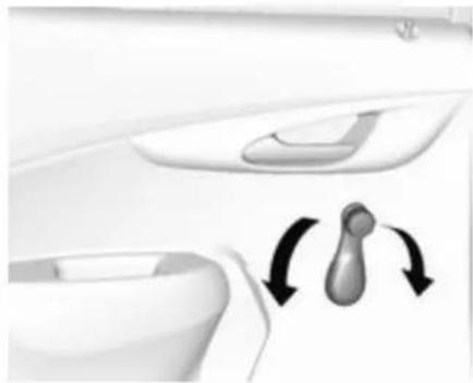
The windows can be opened or closed manually with the window cranks.
28 Keys, doors and windows
Power windows
⚠ Warning
Take care when operating the power windows. Risk of injury, particularly to children.
Be careful when closing the windows. Ensure that nothing becomes trapped in them as they move.
Operable with ignition on (position 2) 104.
Retained power off 105.

Operate the switch in the door trim for the respective window by pushing to open or pulling to close.
Open
Short push: window opens in stages.
Long push: window opens automatically up to end position. To stop movement, move switch in opposite direction.
Close
Short pull: window closes in stages. Longer pull: window closes automatically up to end position. To stop movement, move switch in opposite direction.
Safety function
If the window glass encounters resistance above the middle of the window during automatic closing, it is immediately stopped and opened again.
Override safety function
In the event of closing difficulties due to frost or the like, switch on the ignition, then pull the switch several times to close the windows in stages.
Child safety system for rear windows

Press ☑ to deactivate rear door power windows; the LED illuminates. To activate, press ☑ again.
Overload
If the windows are repeatedly operated at short intervals, the window operation is disabled for some time.
Initialising the power windows
If the windows cannot be opened or closed automatically (e.g. after disconnecting the vehicle battery), activate the window electronics as follows:
- Close the doors.
- Switch on ignition.
- Close the window completely and operate the button for an additional two seconds.
- Repeat this procedure for each window.
Heated rear window
Operated by pressing ☐.
Rear window heating works with the engine running.
It is switched off automatically after a short time.
Sun visors
The sun visors can be folded down or swivelled to the side to prevent dazzling.
The integral mirrors should be closed when driving.
Roof
Sunroof
Warning
Take care when operating the sunroof. Risk of injury, particularly to children.
Keep a close watch on the movable parts when operating them. Ensure that nothing becomes trapped in them as they move.
Operable via a rocker switch with ignition on (position 2) ↩ 104.
Retained power off ➔ 105.
30 Keys, doors and windows

Raise
Hold switch 🙏 depressed until the sunroof is raised at the rear.
Open
From raised position press and release switch 📄: the sunroof is opened automatically up to end position. To stop movement before end position, operate switch once more.
Close
Hold switch 🔒 depressed from any position until sunroof is closed completely. Releasing the switch stops movement in any position.
Notice
If the top of the roof is wet, tilt sunroof, allow water to run off and then open sunroof.
Do not affix any stickers to sunroof.
Sunblind
The sunblind is manually operated. Close or open the sunblind by sliding. When the sunroof is open, the sunblind is always open.
Seats, restraints
Head restraints 31
Front seats 32
Seat position 32
Seat adjustment 33
Heating 34
Seat belts 35
Three-point seat belt 36
Airbag system 37
Front airbag system 40
Side airbag system 41
Curtain airbag system 41
Airbag deactivation 42
Child restraints 43
Child restraint systems .... 43
Child restraint installation locations 45
ISOFIX child restraint systems .. 48
Top-tether fastening eyes ..... 48
Head restraints
Position
⚠ Warning
Only drive with the head restraint set to the proper position.

The upper edge of the head restraint should be at upper head level. If this is not possible for extremely tall people, set to highest position, and set to lowest position for small people.
Adjustment
Front head restraints, height adjustment

Press release button, adjust height, engage.
32 Seats, restraints
Rear head restraints, height adjustment

Pull the head restraint upwards and let engage. To move downwards, press the catch to release and push the head restraint downwards.
Removal of rear head restraint E.g. when using a child restraint system 43.

Press both catches, pull the head restraint upwards and remove.
Front seats
Seat position
Warning
Only drive with the seat correctly adjusted.
Danger
Do not sit nearer than 25 cm from the steering wheel, to permit safe airbag deployment.
Warning
Never adjust seats while driving as they could move uncontrollably.
Warning
Never store any objects under the seats.

- Sit with buttocks as far back against the backrest as possible. Adjust the distance between the seat and the pedals so that legs are slightly angled when fully pressing the pedals. Slide the front passenger seat as far back as possible.
-
Set seat height high enough to have a clear field of vision on all sides and of all display instruments. There should be at least one hand of clearance between head and the roof frame. Your thighs should rest lightly on the seat without pressing into it.
-
Sit with shoulders as far back against the backrest as possible. Set the backrest rake so that it is possible to easily reach the steering wheel with arms slightly bent. Maintain contact between shoulders and the backrest when turning the steering wheel. Do not angle the backrest too far back. We recommend a maximum rake of approx. 25°.
- Adjust seat and steering wheel in a way that the wrist rests on top of the steering wheel while the arm is fully extended and shoulders on the backrest.
- Adjust the steering wheel ⇒ 57.
- Adjust the head restraint ➕ 31.
- Adjust the seat belt ⇒ 36.
Seat adjustment
Drive only with engaged seats and backrests.
Longitudinal adjustment

Pull handle, slide seat, release handle. Try to move the seat back and forth to ensure that the seat is locked in place.
34 Seats, restraints
Backrest inclination
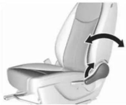
Pull lever, adjust inclination and release lever. Allow the backrest to engage audibly.
Seat height

Lever pumping motion up : seat higher down : seat lower
Heating

Activate seat heating by pressing 🌐 for the respective front seat.
The LED in the button illuminates to indicate activation.
Pressing ⏻ once more deactivates seat heating.
Seat heating is operational when engine is running.
During an Autostop, seat heating is also operational.
Stop-start system ↩ 106.
Seat belts
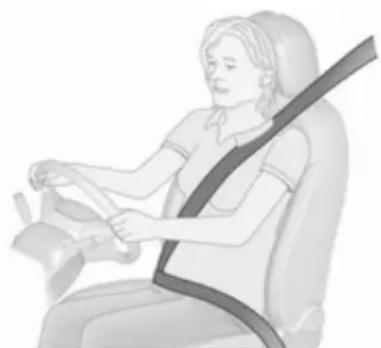
The seat belts are locked during heavy acceleration or deceleration of the vehicle holding the occupants in the sitting position. Therefore the risk of injury is considerably reduced.
⚠ Warning
Fasten seat belt before each trip. In the event of an accident, people not wearing seat belts endanger their fellow occupants and themselves.
Seat belts are designed to be used by only one person at a time. Child restraint system 43.
Periodically check all parts of the belt system for damage, pollution and proper functionality.
Have damaged components replaced. After an accident, have the belts and triggered belt pretensioners replaced by a workshop.
Notice
Make sure that the belts are not damaged by shoes or sharp-edged objects or are trapped. Prevent dirt from getting into the belt retractors.
Seat belt reminder
Front seats are equipped with a seat belt reminder, indicated for driver seat as control indicator in the tachometer 68, and for front passenger seat as control indicator in the Driver Information Centre 65.
Belt force limiters
Stress on the body is reduced by the gradual release of the belt during a collision.
Belt pretensioners
In the event of a head-on or rear-end collision of a certain severity, the front seat belts are tightened.
Warning
Incorrect handling (e.g. removal or fitting of belts) can trigger the belt pretensioners.
Deployment of the belt pretensioners is indicated by continuous illumination of control indicator ➡ 68.
Triggered belt pretensioners must be replaced by a workshop. Belt pretensioners can only be triggered once.
Notice
Do not affix or install accessories or other objects that may interfere with the operation of the belt pretensioners. Do not make any
36 Seats, restraints
modifications to belt pretensioner components as this will invalidate the vehicle type approval.
Three-point seat belt
Fasten

Withdraw the belt from the retractor, guide it untwisted across the body and insert the latch plate into the buckle. Tighten the lap belt regularly while driving by pulling the shoulder belt.

Loose or bulky clothing prevents the belt from fitting snugly. Do not place objects such as handbags or mobile phones between the belt and your body.
Warning
The belt must not rest against hard or fragile objects in the pockets of your clothing.
Seat belt reminder 68.
Unfasten
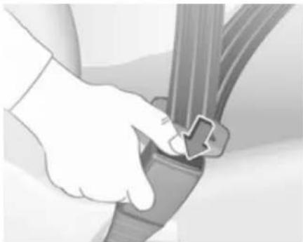
To release belt, press red button on belt buckle.
Using the seat belt while pregnant
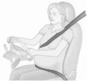
Warning
The lap belt must be positioned as low as possible across the pelvis to prevent pressure on the abdomen.
Airbag system
The airbag system consists of a number of individual systems depending on the scope of equipment.
When triggered, the airbags inflate within milliseconds. They also deflate so quickly that it is often unnoticeable during the collision.
Warning
If handled improperly the airbag systems can be triggered in an explosive manner.
Notice
The airbag systems and belt pretensioner control electronics are located in the centre console area. Do not put any magnetic objects in this area.
Do not affix any objects onto the airbag covers and do not cover them with other materials.
Each airbag is triggered only once. Have deployed airbags replaced by a workshop. Furthermore, it may be
necessary to have the steering wheel, the instrument panel, parts of the panelling, the door seals, handles and the seats replaced.
Do not make any modifications to the airbag system as this will invalidate the vehicle type approval.
When the airbags inflate escaping hot gases may cause burns.
Fault
If there is a fault in the airbag system, the control indicator 🚗 illuminates and a message or a warning code appears in the Driver Information Centre. The system is not operational.
Have the cause of the fault remedied by a workshop.
Control indicator for airbag systems 68.
Child restraint systems on front passenger seat with airbag systems

EN: NEVER use a rearward-facing child restraint on a seat protected by an ACTIVE AIRBAG in front of it; DEATH or SERIOUS INJURY to the CHILD can occur.
Beyond the warning required by ECE R94.02, for safety reasons a forward-facing child restraint system must only be used subject to the instructions and restrictions in the tables 45.
The airbag label is located on both sides of the front passenger sun visor. Airbag deactivation ⇒ 42.
Front airbag system
The front airbag system consists of one airbag in the steering wheel and one in the instrument panel on the front passenger side. The location is identified by the word AIRBAG.
The front airbag system is triggered in the event of a front-end impact of a certain severity. The ignition must be switched on.

The inflated airbags cushion the impact, thereby reducing the risk of injury to the upper body and head of the front seat occupants considerably.

Warning
Optimum protection is only provided when the seat is in the proper position.
Seat position ↩ 32.
Keep the area in which the airbag inflates clear of obstructions.
Fit the seat belt correctly and engage securely. Only then is the airbag able to protect.
Side airbag system

The side airbag system consists of an airbag in each front seat backrest. The location is identified by the word AIRBAG.
The side airbag system is triggered in the event of a side impact of a certain severity. The ignition must be switched on.

The inflated airbags cushion the impact, thereby reducing the risk of injury to the upper body and pelvis in the event of a side-on collision considerably.
Warning
Keep the area in which the airbag inflates clear of obstructions.
Notice
Only use protective seat covers that have been approved for the vehicle. Be careful not to cover the airbags.
Curtain airbag system
The curtain airbag system consists of an airbag in the roof frame on each side. The location is identified by the word AIRBAG on the roof pillars.
The curtain airbag system is triggered in the event of a side-on impact of a certain severity. The ignition must be switched on.

The inflated airbags cushion the impact, thereby reducing the risk of injury to the head in the event of a side-on impact considerably.
42 Seats, restraints

Warning
Keep the area in which the airbag inflates clear of obstructions.
The hooks on the handles in the roof frame are only suitable for hanging up light articles of clothing, without coat hangers. Do not keep any items in these clothes.
Airbag deactivation
The front passenger airbag system must be deactivated for a child restraint system on the passenger seat according to the instructions in the tables 45.
The other airbag systems, the belt pretensioners and all driver airbag systems will remain active.

Use the ignition key to choose the switch position:
2 OFF : front passenger airbag is deactivated and will not inflate in the event of a collision. Control indicator 2 OFF illuminates continuously
ON : front passenger airbag is active

Danger
Deactivate passenger airbag only in combination with the use of a child restraint system, subject to the instructions and restrictions in the tables 45.
Otherwise, there is a risk of fatal injury for a person occupying a seat with a deactivated front passenger airbag.
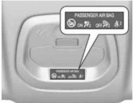
If control indicator on % illuminates for approx. 60 seconds after the ignition is switched on, the front passenger airbag system will inflate in the event of a collision.
If both control indicators are illuminated at the same time, there is a system failure. The status of the system is not discernible, therefore no person is allowed to occupy the front passenger seat. Contact a workshop immediately.
Change status only when the vehicle is stopped with the ignition off.
Status remains until the next change.
Control indicator for airbag deactivation ⇒ 68.
Child restraints
Child restraint systems
We recommend Vauxhall child restraint systems which are tailored specifically to the vehicle.
The following child restraints are recommended for the following weight classes:
- Group 0, Group 0+ Maxi Cosi Cabriofix with ISOFIX base, for children up to 13 kg
- Group I Duo Plus with ISOFIX and Top tether, for children from 9 kg to 18 kg in this group
- Group II, Group III Kidfix with or without ISOFIX for children from 15 kg to 36 kg
When a child restraint system is being used, pay attention to the following usage and installation instructions and also those supplied with the child restraint system.
Always comply with local or national regulations. In some countries, the use of child restraint systems is forbidden on certain seats.
Danger
If using a rear-facing child restraint system on the front passenger seat, the airbag system for the front passenger seat must be deactivated. This also applies to certain forward-facing child restraint systems as indicated in the tables ⇒ 45.
Airbag deactivation 42.
Airbag label ➔ 37.
Selecting the right system
The rear seats are the most convenient location to fasten a child restraint system.
Children should travel facing rearwards in the vehicle as long as possible. This ensures that the child's backbone, which is still very weak, is under less strain in the event of an accident.
44 Seats, restraints
Only use suitable restraint systems, e.g. those that comply with valid UN ECE regulations.
Ensure that the child restraint system to be installed is compatible with the vehicle type. Refer to the tables on the following pages, the instructions supplied with the child restraint system and the vehicle type list of non-universal child restraint systems.
Ensure that the mounting location of the child restraint system within the vehicle is correct, see following tables.
Remove rear head restraint before mounting a child restraint system if required.
Allow children to enter and exit the vehicle only on the side facing away from the traffic.
When the child restraint system is not in use, secure the seat with a seat belt or remove it from the vehicle.
Child restraint systems could be fastened with ISOFIX mounting brackets, Top-tether if available, and/or a three-point seat belt. Refer to the following tables.
Notice
Do not affix anything on the child restraint systems and do not cover them with any other materials.
A child restraint system which has been subjected to stress in an accident must be replaced.
Child restraint installation locations
Permissible options for fastening a child restraint system with a three-point seat belt
On front passenger seat
| Weight and age class | On rear outboard seats | On rear centre seatactivated | ||
| Group 0: up to 10 kg or approx. 10 months | X | U1 | U2 | X |
| Group 0+: up to 13 kg or approx. 2 years | X | U1 | U2 | X |
| Group I: 9 to 18 kg or approx. 8 months to 4 years | X | U1 | U2 | X |
| Group II: 15 to 25 kg or approx. 3 to 7 years | X | X | U2 | X |
| Group III: 22 to 36 kg or approx. 6 to 12 years | X | X | U2 | X |
U : universal suitability in conjunction with three-point seat belt
X : no child restraint system permitted in this weight class
1 : adjust seat backrest inclination as far as necessary to a vertical position to ensure that the belt runs forwards from the upper anchorage point
2 : move the driver and/or passenger seat forwards and adjust seat backrest inclination as far as necessary to a vertical position to ensure that the child restraint system does not have any interference from the front seat backrest.
46 Seats, restraints
| Permissible options for fitting an ISOFIX child restraint system | ||||
| Weight class Size class Fixture | On front passenger seat | On rear outboard seats On rear centre seat | ||
| Group 0: up to 10 kg or approx. 10 months | F ISO/L1 X X X | |||
| G ISO/L2 X X X | ||||
| E ISO/R1 X IL X | ||||
| Group 0+: up to 13 kg or approx. 2 years | E ISO/R1 X IL X | |||
| D ISO/R2 X IL X | ||||
| C ISO/R3 X | IL1 | X | ||
| Group I: 9 to 18 kg or approx. 8 months to 4 years | D ISO/R2 X IL X | |||
| C ISO/R3 X | IL1 | X | ||
| B ISO/F2 X | IL, IUF | X | ||
| B1 ISO/F2X | X | IL, IUF | X | |
| A ISO/F3 X | IL, IUF | X | ||
| Group II: 15 to 25 kg or approx. 3 to 7 years | X IL X | |||
| Group III: 22 to 36 kg or approx. 6 to 12 years | X IL X | |||
IL : suitable for particular ISOFIX restraint systems of the "specific-vehicle", "restricted" or "semi-universal" categories. The ISOFIX restraint system must be approved for the specific vehicle type (refer to the vehicle type list of the child restraint system)
IUF : suitable for ISOFIX forward-facing child restraint systems of universal category approved for use in this weight class
X : no ISOFIX child restraint system approved for this weight class
1 : only applicable for rear outer seat on passenger side with foremost seating position and backrest upright.
Notice
Move the driver and/or passenger seat forwards and adjust seat backrest inclination as far as necessary to a vertical position to ensure that the child restraint system does not have any interference from the front seat backrest.
ISOFIX size class and seat device
A - ISO/F3 : forward-facing child restraint system for children of maximum size in the weight class 9 to 18 kg
B - ISO/F2 : forward-facing child restraint system for smaller children in the weight class 9 to 18 kg
B1 - ISO/F2X : forward-facing child restraint system for smaller children in the weight class 9 to 18 kg
C – ISO/R3 : rear-facing child restraint system for children of maximum size in the weight class up to 18 kg
D - ISO/R2 : rear-facing child restraint system for smaller children in the weight class up to 18 kg
E - ISO/R1 : rear-facing child restraint system for young children in the weight class up to 13 kg
F - ISO/L1 : left lateral facing position CRS (carry cot) for smaller children in the weight class up to 10 kg
G - ISO/L2 : right lateral facing position CRS (carry cot) for smaller children in the weight class up to 10 kg.
ISOFIX child restraint systems
Fasten vehicle-approved ISOFIX child restraint systems to the ISOFIX mounting brackets. Specific vehicle ISOFIX child restraint system positions are marked in the table by IL.
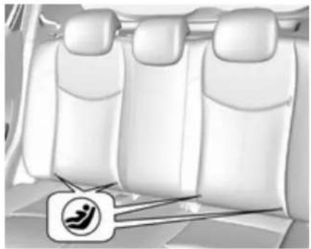
ISOFIX mounting brackets on the rear seats are indicated by the ISOFIX logo on the backrest.
ISOFIX child restraint systems of universal category positions are marked in the table by IUF.
Remove rear head restraint before mounting a child restraint system, if required ⇒ 31.
Route, attach, and tighten the top tether according to your child restraint instructions.
Top-tether fastening eyes
The vehicle has two fastening eyes on the back of the rear seats.
Top-tether fastening eyes are marked with the symbol ⚡ for a child seat.
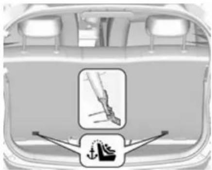
In addition to the ISOFIX mounting, fasten the Top-tether strap to the Top-tether fastening eyes.
Route, attach, and tighten the top tether according to your child restraint instructions.
ISOFIX child restraint systems of universal category positions are marked in the table by IUF.
Remove rear head restraint before mounting a child restraint system, if required ⇒ 31.
Storage
Storage compartments ..... 49
Glovebox 49
Cupholders 49
Centre console storage 50
Load compartment 50
Load compartment cover ..... 52
Rear floor storage cover 53
Warning triangle 53
First aid kit 54
Loading information 54
Storage compartments
Warning
Do not store heavy or sharp objects in the storage compartments. Otherwise, the storage compartment lid could open and vehicle occupants could be injured by objects being thrown around in the event of hard braking, a sudden change in direction or an accident.
Glovebox

Pull lever to open the glovebox cover.
The glovebox features an adapter for the locking wheel bolts.
The glovebox should be closed whilst driving.
Cupholders

Cupholders are located in the centre console.
Centre console storage
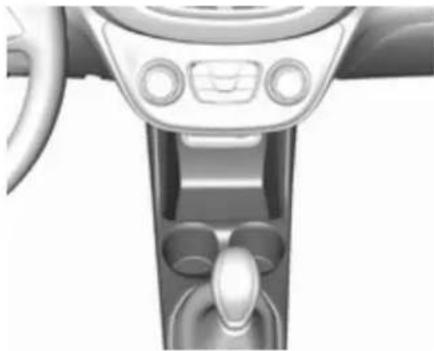
The storage is used for small articles.
Load compartment
Load compartment extension
Caution
First fold up the rear seat cushion before folding the rear seat backrest.
Disregard may lead to damage to the rear seat.
Notice
To ensure sufficient room for rear seat cushion operation, slide the front seats forward and move the front seat backrest upright.

- Pull up the front of the rear seat cushion to release it.
- Guide the rear of the rear seat cushion to an upright position.
- Remove the rear seat head restraints ➔ 31.

- Pull the release knob on top of the rear backrest.

- Fold down the backrest and insert the rear seat head restraints into the pockets.

- Put the seat belts for the outboard seats into the belt guides.
- Adjust the front seats to the desired position.
To return the backrest to the original position:
- Lift the backrest up and pull out the seat belt from the belt guides. Push backrest firmly into place.
⚠ Warning
When folding up, ensure that backrests are securely engaged in position before driving. Failure to do so may result in personal injury
or damage to the load or vehicle in the event of hard braking or a collision.
Ensure the seat belts are not pinched by the latch.
- Reinstall the rear head restraints.
- Place the rear part of the seat cushion in its original position.
Notice
Make sure the seat belts are not twisted or caught under the seat cushion.
4. Push the front part of the seat cushion down firmly until it latches.
The centre rear seat belt may lock when you raise the backrest. If this happens, allow the belt to go back all the way and repeat operation.
If the seat belt is still locked, fold down the seat cushion and try again.
To return the rear seat cushion, put the rear part of the seat cushion in its original position ensuring that the seat belt buckle straps are not twisted
52 Storage
or caught under the seat cushion, then push the front part of the seat cushion firmly down until it latches.
Caution
When returning rear seat backrest to the upright position, place the rear seat belt and buckles between the rear seat backrest and one cushion. Make sure the rear seat belt and buckles do not get pinched under the rear seat cushion.
Ensure the seat belts are not twisted or caught in the seat backrest and are arranged in their proper position.

To remove the rear seat cushion, push the hinges in direction of arrow.
Load compartment cover
Do not place heavy objects on the cover.

Removing
Unhook retaining straps from tailgate.
Lift cover at the rear and push it upwards at the front.
Remove the cover.
Stowing
When the load compartment is fully loaded, stow the load compartment cover on the rear seats or remove from vehicle.
Fitting
Engage cover in side guides and fold downwards. Attach retaining straps to tailgate.
Rear floor storage cover
Rear floor cover
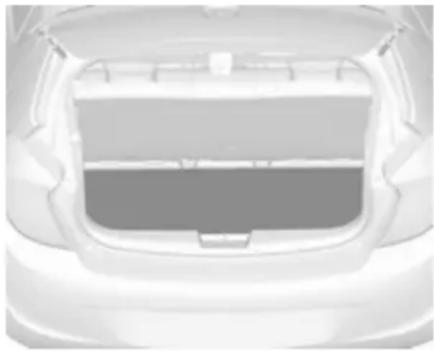
Lift up rear floor cover to gain access to the tyre repair kit, vehicle tools and warning triangle.
On versions with spare wheel, the spare wheel is located under the rear floor cover together with the vehicle tools.
Tools ↩ 149.
General hint
Warning
For safety reasons, stow all parts in the load compartment in its position, always drive with a closed rear floor cover and, if possible, with folded up rear backrests.
Otherwise, vehicle occupants could be injured by objects being thrown around in the event of sharp braking, a sudden change in direction or an accident.
Warning triangle
Vehicles with spare wheel

Stow the warning triangle in the load compartment.
54 Storage
Vehicles with tyre repair kit

Stow the warning triangle in the vehicle tool box below the floor over in the load compartment.
First aid kit

Stow the first-aid kit in the well in the load compartment.
Loading information
- Heavy objects in the load compartment should be placed against the seat backrests. Ensure that the backrests are securely engaged. If objects can be stacked, heavier objects should be placed at the bottom.
- Secure loose objects in the load compartment to prevent them from sliding.
- When transporting objects in the load compartment, the backrests of the rear seats must not be angled forward.
- Do not allow the load to protrude above the upper edge of the backrests.
- Do not place any objects on the load compartment cover or the instrument panel, and do not cover the sensor on top of the instrument panel.
- The load must not obstruct the operation of the pedals, parking brake and gear selector lever, or
hinder the freedom of movement of the driver. Do not place any unsecured objects in the interior.
- Do not drive with an open load compartment.
⚠ Warning
Always make sure that the load in the vehicle is securely stowed. Otherwise objects can be thrown around inside the vehicle and cause personal injury or damage to the load or vehicle.
- The payload is the difference between the permitted gross vehicle weight (see identification plate 173) and the EC kerb weight.
To calculate the payload, enter the data for your vehicle in the weights table at the front of this manual.
The EC kerb weight includes weights for the driver (68 kg), luggage (7 kg) and all fluids (fuel tank 90% full).
Optional equipment and accessories increase the kerb weight.
- Driving with a roof load increases the sensitivity of the vehicle to cross-winds and has a detrimental effect on vehicle handling due to the vehicle's higher centre of gravity. Distribute the load evenly and secure it properly with retaining straps. Adjust the tyre pressure and vehicle speed according to the load conditions. Check and retighten the straps frequently.
56 Instruments and controls
Instruments and controls
Controls 57
Steering wheel adjustment ..... 57
Steering wheel controls 57
Heated steering wheel 57
Horn 58
Windscreen wiper/washer ..... 58
Rear window wiper/washer ..... 59
Outside temperature 59
Clock 59
Power outlets 61
Cigarette lighter 61
Ashtrays 61
Warning lights, gauges and indicators 61
Instrument cluster 61
Speedometer 61
Odometer 62
Trip odometer 62
Tachometer 62
Fuel gauge 62
Fuel selector 63
Engine coolant temperature gauge 64
Service display 64
Control indicators 65
Turn signal 67
Seat belt reminder 68
Airbag and belt tensioners ..... 68
Airbag deactivation 68
Charging system 69
Malfunction indicator light ...... 69
Service vehicle soon 69
Brake and clutch system ...... 69
Operate pedal 69
Antilock brake system (ABS) ..... 70
Gear shifting 70
Power steering 70
Lane departure warning 70
Ultrasonic parking assist ..... 70
Electronic Stability Control off ...70
Electronic Stability Control and Traction Control system .... 70
Traction Control system off ..... 71
Engine coolant temperature ..... 71
Tyre pressure monitoring system 71
Engine oil pressure 71
Low fuel 72
Immobiliser 72
Reduced engine power 72
Exterior light 72
High beam 72
Fog light 72
Rear fog light 72
Cruise control 72
Speed limiter 72
Bonnet open 72
Door open 73
Information displays 73
Driver Information Centre 73
Info display 78
Vehicle messages 79
Warning chimes 81
Battery voltage 81
Vehicle personalisation 82
OnStar 84
Controls
Steering wheel adjustment

Unlock lever, adjust steering wheel, then engage lever and ensure it is fully locked.
Do not adjust steering wheel unless vehicle is stationary and steering wheel lock has been released.
Steering wheel controls

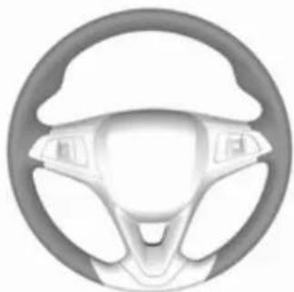
Driver Information Centre, some driver assistance systems, Infotainment system and a connected mobile phone can be operated via the controls on the steering wheel.
Driver assistance systems ➔ 119. Further information is available in the Infotainment manual.
Heated steering wheel

Activate heating by pressing ⚙. Activation is indicated by the LED in the button.
58 Instruments and controls
The grip areas of the steering wheel are heated quicker and to a higher temperature than the other areas.
Heating is operational when the engine is running and during an Autostop.
Stop-start system ↩ 106.
Horn

Press ▶.
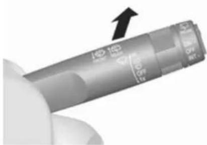
Windscreen wiper/washer
Windscreen wiper

HI : fast
LO : slow
: interval wiping
OFF : off
For a single wipe when the windscreen wiper is off, press the lever down to position 🔒.
Do not use if the windscreen is frozen.
Switch off in car washes.
Windscreen washer

Pull lever. Washer fluid is sprayed onto the windscreen and the wiper wipes a few times.
Washer fluid ➔ 135
Rear window wiper/washer

Press the rocker switch to activate the rear window wiper:
upper position : continuous
operation
lower position : intermittent
operation
middle position : off
Push lever. Washer fluid is sprayed onto the rear window and the wiper wipes a few times.
Do not use if the rear window is frozen.
Switch off in car washes.
The rear window wiper comes on automatically when the windscreen wiper is switched on and reverse gear is engaged.
Activation or deactivation of this function can be changed in the menu Settings in the Info-Display.
Washer fluid ➔ 135
Vehicle personalisation ➔ 82.
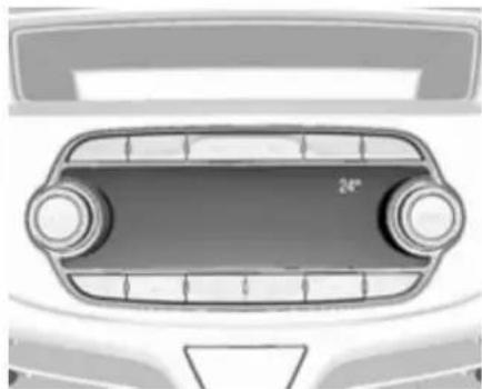
Outside temperature
A drop in temperature is indicated immediately and a rise in temperature after a time delay.
Warning
The road surface may already be icy even though the display indicates a few degrees above 0 °C.
Clock
Date and time are shown in the Info-Display.
Info-Display ↩ 78
Graphic-Info-Display
Press MENU to open the respective audio menu.

Select Time and Date.
Set Time
Select Set Time to enter the respective submenu.
Select Auto Set at the bottom of the screen. Activate either On - RDS or Off (Manual).
If Off (Manual) is selected, adjust hours and minutes.
Repeatedly select 12-24 HR at the bottom of the screen to choose a time mode.
If the 12-hour mode is selected, a third column for AM and PM selection is displayed. Select the desired option.
Set Date
Select Set Date to enter the respective submenu.
Select Auto Set at the bottom of the screen. Activate either On - RDS or Off (Manual).
If Off (Manual) is selected, adjust the date settings.
7" Colour-Info-Display
Press 🔊 and then select Settings.
Select Time and Date to display the respective submenu.

Set Time Format
To select the desired time format, touch the screen buttons 12 h or 24 h.
Set Date Format
To select the desired date format, select Set Date Format and choose between the available options in the submenu.
Auto Set
To choose whether time and date are to be set automatically or manually, select Auto Set.
For time and date to be set automatically, select On - RDS.
For time and date to be set manually, select Off - Manual. If Auto Set is set to Off - Manual, the submenu items Set Time and Set Date become available.
Set time and date
To adjust the time and date settings, select Set Time or Set Date.
Touch + and - to adjust the settings.
Power outlets

A 12 Volt power outlet is located in the centre console.
Do not exceed the maximum power consumption of 120 watts.
With ignition off, the power outlet is deactivated. Additionally, the power outlet is deactivated in the event of low vehicle battery voltage.
Electrical accessories that are connected must comply with the electromagnetic compatibility requirements laid down in DIN VDE 40 839.
Do not connect any current-delivering accessories, e.g. electrical charging devices or batteries.
Do not damage the outlet by using unsuitable plugs.
Stop-start system ↩ 106.
Cigarette lighter
The cigarette lighter may be located in the centre console.
Press in cigarette lighter. It switches off automatically once the element is glowing. Pull out lighter.
Ashtrays
Caution
To be used only for ash and not for combustible rubbish.
The portable ashtray can be placed in the cupholders.
Warning lights, gauges and indicators
Instrument cluster
The needles of the instruments briefly rotate to the end position when the ignition is switched on.
Speedometer

Indicates vehicle speed.
62 Instruments and controls
Odometer
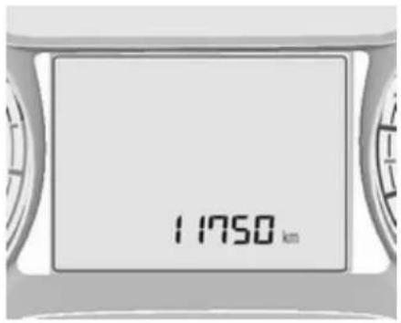
The bottom line displays the recorded distance in miles.
Trip odometer
The recorded distance is displayed since the last reset.
Trip odometer counts up to 9999.9 miles and then restarts at 0.
To reset, press SET/CLR on the turn signal lever for a few seconds ◇ 73.
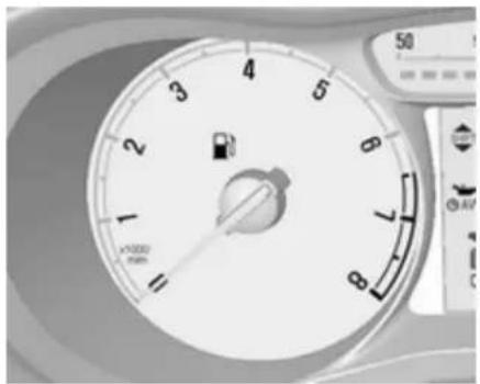
Tachometer

Displays the engine speed.
Drive in a low engine speed range for each gear as much as possible.
| Caution |
| If the needle is in the red warning zone, the maximum permitted engine speed is exceeded. Engine at risk. |
Fuel gauge

Number of LEDs displays the level in the fuel tank.
The arrow indicates the vehicle side where the fuel filler flap is located.
During liquid gas operation, the level in the gas tank is displayed.
Control indicator ▶ illuminates if the level in the tank is low. Refuel immediately if it flashes.
During liquid gas operation, the system automatically switches over to petrol operation when gas tanks are empty ⇔ 63.
Never run the fuel tank dry.
Because of the fuel remaining in the tank, the top-up quantity may be less than the specified tank capacity.
Fuel selector

Press LPG to switch between petrol and liquid gas operation. The LED in the button shows the current operating mode.
LED off : petrol operation
LED : checking conditions for flashes fuel transition to liquid gas operation.
Illuminates if conditions are fulfilled.
LED illu- : liquid gas operation minates
LED : liquid gas tank is empty flashes or failure in liquid gas five system. A message is times displayed in the Driver and Information Centre. extinguishes
As soon as the liquid gas tank is empty, petrol operation is automatically engaged until the ignition is switched off.
Fuel for liquid gas operation ⇒ 125.
64 Instruments and controls
Engine coolant temperature gauge
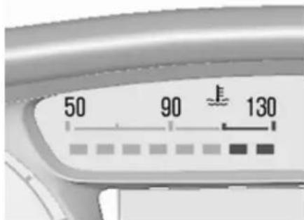
Number of LEDs displays the coolant temperature.
up to 2 LEDs : engine operating temperature not yet reached
3 to 6 LEDs : normal operating temperature
more than 6 LEDs : temperature too high
Caution
If engine coolant temperature is too high, stop vehicle, switch off engine. Danger to engine. Check coolant level.
Service display
The engine oil life system lets you know when to change the engine oil and filter. Based on driving conditions, the interval at which an engine oil and filter change will be indicated can vary considerably.

The remaining engine oil life duration is displayed in percent in the Driver Information Centre.
To display the remaining engine oil life duration use turn signal lever buttons:
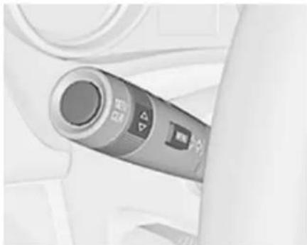
Press MENU to select the Vehicle Information Menu.
Turn the adjuster wheel to select Remaining Oil Life.
Reset
Press SET/CLR on turn signal lever for several seconds to reset. The remaining engine oil life duration menu must be active. Switch on ignition, but not the engine.
The system must be reset every time the engine oil is changed to ensure proper functionality. Seek the assistance of a workshop.
Next service
When the system has calculated that engine oil life has diminished, a warning message appears in the Driver Information Centre. Have engine oil and filter changed by a workshop within one week or 300 miles (whichever occurs first).
Driver Information Centre ↩ 73.
Service information ↩ 169.
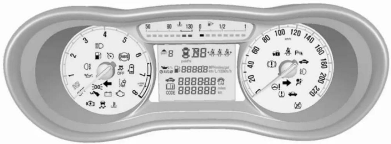
Control indicators
The control indicators described are not present in all vehicles. The description applies to all instrument versions.
Depending on the equipment, the position of the control indicators may vary. When the ignition is switched on, most control indicators will illuminate briefly as a functionality test.
The control indicator colours mean: red : danger, important reminder yellow : warning, information, fault green : confirmation of activation blue : confirmation of activation white : confirmation of activation
Control indicators in the instrument cluster
Control indicators in the overhead console

Overview
Turn signal 67
Seat belt reminder ➔ 68
Airbag and belt tensioners 68
Airbag deactivation 68
Charging system ➔ 69
Malfunction indicator light 69
Service vehicle soon ↩ 69
(1) Brake and clutch system → 69
Operate pedal 69
(ABS) Antilock brake system (ABS) 70
▲ Upshift ➔ 70
! Power steering ⇒ 70
Lane departure warning 70
P▲ Ultrasonic parking assist 70
Electronic Stability Control off 70
Electronic Stability Control and Traction Control system 70
Traction Control system off 71
Engine coolant temperature 71
(1) Tyre pressure monitoring system ➔ 71
Engine oil pressure 71
Low fuel 72
Immobiliser 72
Reduced engine power ➔ 72
Exterior light 72
ED High beam 72
D Fog light ➔ 72
0‡ Rear fog light ➔ 72
Cruise control 72
Speed limiter 72
Bonnet open 72
Door open ➔ 73
Turn signal
◇◇ illuminates or flashes green.
Illuminates briefly
The parking lights are switched on.
Flashes
A turn signal or the hazard warning flashers are activated.
68 Instruments and controls
Rapid flashing: failure of a turn signal light or associated fuse.
Bulb replacement 138, Fuses 144.
Turn signals ⇒ 90.
Seat belt reminder
Seat belt reminder on front seats
4 for driver's seat illuminates or flashes red in the speedometer.

42 for front passenger seat illuminates or flashes red in the overhead console when the seat is occupied.
Illuminates
After the ignition has been switched on, until the seat belt has been fastened.
Flashes
After having started the engine, for a maximum of 100 seconds, until the seat belt has been fastened.
Fastening the seat belt ➔ 36.
Seat belt status on rear seats
in the Driver Information Centre flashes or illuminates.
Illuminates
After having started the engine for a minimum of 35 seconds, until the seat belt has been fastened.
Flashes
After starting-off, when the seat belt is unfastened.
Fastening the seat belt ➔ 36.
Airbag and belt tensioners
illuminates red.
When the ignition is switched on, the control indicator illuminates for approx. four seconds. If it does not illuminate, does not go out after four seconds or illuminates whilst driving, there is a fault in the airbag system. Seek the assistance of a workshop. The airbags and belt pretensioners may fail to trigger in the event of an accident.
Deployment of the belt pretensioners or airbags is indicated by continuous illumination of ⚠.
Warning
Have the cause of the fault remedied immediately by a workshop.
Belt pretensioners, airbag system ⇒ 35, ⇒ 37.
Airbag deactivation
ON illuminates yellow.
The front passenger airbag is activated.
OFF illuminates yellow.
The front passenger airbag is deactivated ⇒ 42.

Danger
Risk of fatal injury for a child using a child restraint system together with activated front passenger airbag.
Risk of fatal injury for an adult person with deactivated front passenger airbag.
Charging system
-+ illuminates red.
Illuminates when the ignition is switched on and extinguishes shortly after the engine starts.
Illuminates when the engine is running
Stop, switch off engine. Vehicle battery is not charging. Engine cooling may be interrupted. The brake servo unit may cease to be effective. Seek the assistance of a workshop.
Malfunction indicator light
illuminates or flashes yellow.
Illuminates when the ignition is switched on and extinguishes shortly after the engine starts.
Illuminates when the engine is running
Fault in the emission control system. The permitted emission limits may be exceeded. Seek the assistance of a workshop immediately.
Flashes when the engine is running
Fault that could lead to catalytic converter damage. Ease up on the accelerator until the flashing stops. Seek the assistance of a workshop immediately.
Service vehicle soon
illuminates yellow.
Additionally, a warning code is displayed in the Driver Information Centre.
The vehicle requires a service.
Seek the assistance of a workshop. Vehicle messages ➔ 79.
Brake and clutch system
(1) illuminates red.
The brake and clutch fluid level is too low, when manual parking brake is not applied ⇒ 136.

Warning
Stop. Do not continue your journey. Consult a workshop.
Illuminates when the manual parking brake is applied and ignition is switched on 115.
Operate pedal
- illuminates or flashes yellow.
Illuminates
Clutch pedal must be depressed to start the engine in Autostop mode. Stop-start system ➔ 106.
70 Instruments and controls
Flashes
Pedal must be depressed for a main start of the engine ⇒ 16, ⇒ 105.
Antilock brake system (ABS)
(ABS) illuminates yellow.
Illuminates for a few seconds after the ignition is switched on. The system is ready for operation when the control indicator extinguishes.
If the control indicator does not go out after a few seconds, or if it illuminates while driving, there is a fault in the ABS. The brake system remains operational but without ABS regulation.
Antilock brake system ↩ 114.
Gear shifting
with the number of the recommended gear is indicated, when upshifting is recommended for fuel saving reasons.
Power steering
☉! illuminates yellow.
Illuminates with power steering disabled
Failure in the power steering system. Consult a workshop.
Illumination of ⬤! and ≈ simultaneously
Power steering system must be calibrated, system calibration ⇒ 118.
Lane departure warning
illuminates green or flashes yellow.
Illuminates green
System is switched on and ready to operate.
Flashes yellow
System recognises an unintended lane change.
Lane departure warning ➔ 123.
Ultrasonic parking assist
P illuminates yellow.
Fault in system
or
Fault due to sensors that are dirty or covered by ice or snow
or
Interference due to external sources of ultrasound. Once the source of interference is removed, the system will operate normally.
Have the cause of the fault in the system remedied by a workshop.
Ultrasonic parking assist ➔ 122.
Electronic Stability Control off
illuminates yellow.
The system is deactivated.
Electronic Stability Control and Traction Control system
flashes or illuminates yellow.
Flashes
The system is actively engaged. Engine output may be reduced and the vehicle may be braked automatically to a small degree.
Illuminates
A fault in the system is present. A warning code appears in the Driver Information Centre. Continued driving is possible. The system is not operational. Driving stability, however, may deteriorate depending on road surface conditions.
Have the cause of the fault remedied by a workshop.
Electronic Stability Control 117, Traction Control system 116.
Traction Control system off
② illuminates yellow.
The system is deactivated.
Engine coolant temperature
illuminates red.
Illuminates when the engine is running
Stop, switch off engine.
Caution
Coolant temperature too high.
Check coolant level 135.
If there is sufficient coolant, consult a workshop.
Tyre pressure monitoring system
(1) illuminates or flashes yellow.
Illuminates
Tyre pressure loss. Stop immediately and check tyre pressure.
Flashes
Fault in system or tyre without pressure sensor mounted (e.g. spare wheel). After 60-90 seconds the control indicator illuminates continuously. Consult a workshop.
Tyre pressure monitoring system 151.
Engine oil pressure
illuminates red.
Illuminates when the ignition is switched on and extinguishes shortly after the engine starts.
Illuminates when the engine is running
Caution
Engine lubrication may be interrupted. This may result in damage to the engine and/or locking of the drive wheels.
- Depress the clutch.
- Set selector lever to neutral.
- Move out of the flow of traffic as quickly as possible without impeding other vehicles.
- Switch off the ignition.
72 Instruments and controls

Warning
When the engine is off, considerably more force is needed to brake and steer.
During an Autostop, the brake servo unit will still be operational.
Do not remove key until vehicle is stationary, otherwise the steering wheel lock could engage unexpectedly.
Check oil level before seeking the assistance of a workshop 134.
Low fuel
illuminates or flashes yellow.
Illuminates
Level in fuel tank is too low.
Flashes
Fuel used up. Refuel immediately.
Never run the fuel tank dry.
Refuelling ➔ 127.
Catalytic converter 110.
Immobiliser
flashes yellow.
Fault in the immobiliser system. The engine cannot be started.
Reduced engine power
illuminates yellow.
The engine power is limited. Consult a workshop.
Exterior light
⇒ illuminates green.
The exterior lights are on ⇒ 88.
High beam
ID illuminates blue.
Illuminated when high beam is on or during headlight flash ⇒ 88.
Fog light
≠D illuminates green.
The front fog lights are on ⇒ 90.
Rear fog light
illuminates yellow.
The rear fog light is on ⇒ 90.
Cruise control
illuminates white or green.
Illuminates white
The system is on.
Illuminates green
Cruise control is active.
Cruise control 119.
Speed limiter
illuminates in the Driver
Information Centre when Speed
limiter is active. Set speed is indicated alongside ⚙ symbol.
Speed limiter 121.
Bonnet open
→ illuminates yellow.
Illuminates when the bonnet is open.
Stop-start system ↩ 106.
Door open
② illuminates.
A door or the tailgate is open.
Information displays
Driver Information Centre
The Driver Information Centre is located in the instrument cluster.

Some of the displayed functions differ when the vehicle is being driven or at a standstill. Some functions are only available when the vehicle is being driven.
Main menus are:
- trip/fuel information, see description below
- vehicle information, see description below
The following indications appear when appropriate:
- warning codes ➔ 79
• gear shift indication ➔ 70 - tyre pressure warning ➕ 151
- seat belt reminder indication
68
• service information ➔ 69
Selecting menus and functions
The menus and functions can be selected via the buttons on the turn signal lever.

74 Instruments and controls
Press MENU to switch between the main menus or to return from a submenu to the next higher menu level.
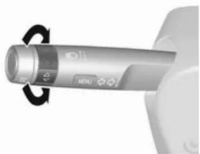
Turn the adjuster wheel to select a submenu of the main menu or to set a numeric value.

Press SET/CLR to select a function or to confirm a message.
Vehicle and service messages are popped-up in the Driver Information Centre if required. Confirm messages by pressing SET/CLR. Vehicle messages 79.
Trip/Fuel information
Possible pages are:
Trip odometer
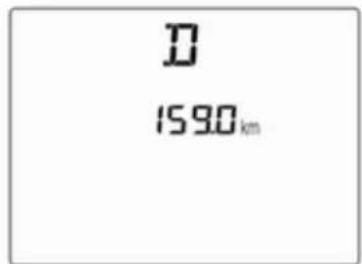
Trip odometer displays the current distance since a certain reset.
Trip odometer counts up to 9999 miles and then restarts at 0.
To reset, press SET/CLR for a few seconds.
Fuel range

Range is calculated from current fuel tank level and current consumption. The display shows average values.
After refuelling, the range is updated automatically after a brief delay.
When the fuel level in the tank is low, a message appears on the display and control indicator ☐ in the fuel gauge illuminates.
When the tank must be refuelled immediately, a warning code appears and remains on the display.
Additionally, control indicator ■ flashes in the fuel gauge → 72.
Fuel range, LPG version Display of the approximate total fuel range for each fuel tank (LPG and petrol).
Average vehicle speed

Display of average speed. The measurement can be reset at any time.
To reset, press SET/CLR for a few seconds while viewing this page.
Instantaneous fuel economy
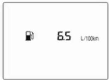
Display of the instantaneous consumption.
On vehicles with LPG engines: Instantaneous consumption is indicated for the currently selected mode, LPG or petrol.
76 Instruments and controls
Average fuel economy

Display of average consumption. The measurement can be reset at any time and starts with a default value.
To reset, press SET/CLR for a few seconds while viewing this page.
On vehicles with LPG engines: Average consumption is indicated for the currently selected mode, LPG or petrol.
Timer

Indicates driving time since last reset.
To stop or start timer press SET/CLR.
To reset press and hold SET/CLR for a few seconds.
Vehicle information
Possible pages are:
- unit
• remaining engine oil life indication - tyre pressure
- tyre loading
Unit

Press SET/CLR while page is displayed. Select metric (unit 1) or imperial (unit 2) by turning the adjuster wheel. Press SET/CLR to set the unit of measurement.
Remaining oil life

Indicates an estimate of the oil's useful life. The number in percentage means the current remaining oil life and indicates when to change the engine oil and filter ⇒ 64.
Tyre pressure

Tyre pressures of all wheels are displayed on this page during driving 151.
Tyre learn

This display allows for matching new tire and wheel by the tyre pressure monitoring system sensors 151.
78 Instruments and controls
Tyre load

The tyre pressure category according to the actual tyre inflation pressure can be selected 151.
Outside temperature
Display of current outside temperature.
Language
Select preferred country language as display language.
Time
Display of current time.
Info display
The Info-Display is located in the instrument panel near the instrument cluster.
Depending on the vehicle configuration the vehicle has a
- Graphic-Info-Display or
- 7" Colour-Info-Display with touch-screen functionality
The vehicle has a 7" Colour-Info-Display with touch-screen functionality.
The Info displays can indicate:
- time ⇒ 59
- outside temperature ⇒ 59
- date ⇒ 59
- Infotainment system, see description in the Infotainment manual
- indication of parking assist instructions ↩ 122
- system messages
- settings for vehicle personalisation ➔ 82
Graphic-Info-Display
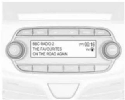
Press ⏻ to switch on the display.
Press MENU to select main menu page.
Turn MENU to select a menu page.
Press MENU to confirm a selection.
Press BACK to exit a menu without changing a setting.
7" Colour-Info-Display
Selecting menus and settings
Menus and settings are accessed via the display.

Press ⏻ to switch on the display.
Press 🔒 to display the homepage.
Tap required menu display icon with the finger.
Tap a respective icon to confirm a selection.
Tap ↩ to return to the next higher menu level.
Press ↗ to return to the homepage.
For further information, see Infotainment manual.
Vehicle personalisation ➔ 82.
Valet mode
Some functions of the Driver Information Centre and the Info-Display can be limited for some drivers.
Activation or deactivation of valet mode can be set in the menu Settings in the vehicle personalisation menu.
Vehicle personalisation ➔ 82.
For more information see Infotainment manual.
Vehicle messages
Messages are indicated mainly in the Driver Information Centre, in some cases together with a warning and signal buzzer.

Press SET/CLR, MENU or turn the adjuster wheel to confirm a message.
Vehicle messages in Driver Information Centre

The vehicle messages are displayed as code numbers.
No. Vehicle message
3 Engine coolant level low
4 Air conditioning off
11 Brakes worn
12 Vehicle overloaded
13 Compressor overheated
No. Vehicle message
15 Centre high-mounted brake light failure
16 Brake light failure
17 Headlight levelling malfunction
18 Left low beam failure
19 Rear fog light failure
20 Right low beam failure
21 Left sidelight failure
22 Right sidelight failure
23 Reversing light failure
24 Number plate light failure
25 Left front turn signal failure
26 Left rear turn signal failure
27 Right front turn signal failure
28 Right rear turn signal failure
35 Replace battery in radio remote control
36 ESC Initialising
No. Vehicle message
49 Lane departure warning unavailable
52 Change timing belt
56 Tyre pressure imbalance on front axle
57 Tyre pressure imbalance on rear axle
59 Open, then close driver window
60 Open, then close front passenger window
61 Open, then close left rear window
62 Open, then close right rear window
65 Theft attempted
66 Service anti-theft alarm system
67 Service steering wheel lock
68 Service power steering
75 Service air conditioning
No. Vehicle message
77 Service lane departure warning
79 Top up engine oil
81 Service transmission
82 Change engine oil soon
84 Engine power reduced
89 Service vehicle soon
95 Service airbag
145 Check washer fluid level
151 Press clutch to start
174 Low vehicle battery
258 Parking assist off
Vehicle messages on Colour-Info-Display
Some important messages appear additionally in the Colour-Info-Display. Some messages only pop-up for a few seconds.
Warning chimes
When starting the engine or whilst driving
Only one warning chime will sound at a time.
The warning chime regarding unfastened seat belts has priority over any other warning chime.
- If seat belt is not fastened.
- If a door or the tailgate is not fully closed when starting off.
- If a certain speed is exceeded with parking brake applied.
- If a programmed speed is exceeded.
- If a warning message appears in the Driver Information Centre or Info-Display.
- If the parking assist detects an object.
- If unintended lane change occurs.
- If a fault in the automatic locking system is detected.
When the vehicle is parked and/or the driver's door is opened
- With exterior lights on.
During an Autostop
- If the driver's door is opened.
Battery voltage
When the vehicle battery voltage is running low, the warning code 174 will appear in the Driver Information Centre.
- Switch off immediately any electrical consumers which are not required for a safe drive, e.g. seat heating, heated windscreen and heated rear window or other main consumers.
- Charge the vehicle battery by driving continuously for a while or by using a charging device.
The warning code will disappear after the engine has been started twice consecutively without a voltage drop. If the vehicle battery cannot be recharged, have the cause of the fault remedied by a workshop.
Vehicle personalisation
The vehicle's behaviour can be personalised by changing the settings in the Info-Display.
Some of the personal settings for different drivers can be memorised individually for each vehicle key. Memorised settings ⇒ 21.
Depending on vehicle equipment and country-specific regulations some of the functions described below may not be available.
Some functions are only displayed or active when the engine is running.
Personal settings
Graphic-Info-Display
Press MENU, when ignition is on and infotainment system is activated.
Turn the MENU button to scroll through the menu list. Press MENU to select the respective menu. To close a menu or to go back to previous page, press BACK.
Select Settings, scroll through the list and select Vehicle Settings

In the corresponding submenus the following settings can be changed:
Vehicle Settings
- Park Assist / Collision Detection
Park Assist: Activates or deactivates the ultrasonic parking assist.
- Comfort Settings
Chime Volume: Changes the volume of warning chimes.
Personalisation by Driver: Activates or deactivates the personalisation function.
Rear Auto Wipe in Reverse: Activates or deactivates
automatic switching on of the rear window wiper when reverse gear is engaged.
• Languages: Scroll through the list and select the desired language.
- Lighting
Exterior lighting by unlocking: Activates or deactivates the entry lighting.
Exit Lighting: Activates or deactivates exit lighting and changes lighting duration.
- Power Door Locks
Stop door lock if door open: Activates or deactivates the door locking function while a door is open.
Delayed Door Lock: Activates or deactivates the delayed door locking function. This feature delays the actual locking of the doors until all doors are closed.
- Remote Lock, Unlock, and Start
Remote Unlock Feedback: Activates or deactivates the hazard warning flasher feedback whilst unlocking.
Remote Lock Feedback:
Changes what kind of feedback is given when locking the vehicle.
Remote Door Unlock: Changes the configuration to unlock only the driver's door or the whole vehicle whilst unlocking.
Auto Relock Doors: Activates or deactivates the automatic relock function after unlocking without opening the vehicle.
- Restore Factory Settings:
Resets all settings to the default settings.
- Valet Mode:
Activated, all vehicle displays are locked and no changes may be performed within the system. See Infotainment manual.
Personal settings
7" Colour-Info-Display
Press 🔒, select Settings and thenVehicle on the touch-screen.

In the corresponding submenus the following settings can be changed:
Settings
• Climate & Air Quality
Auto Fan Max Speed: Modifies the level of the cabin airflow of the climate control in automatic mode.
Air Conditioning Mode: Controls the state of the cooling compressor when the vehicle is started. Last setting (recommended) or at vehicle start is either always on or always off.
Auto Defog: Supports windscreen dehumidification by automatically selecting the necessary settings and automatic air conditioning mode.
Auto Rear Defog: Automatically activates heated rear window.
- Collision / Detection Systems
Park Assist: Activates or deactivates the ultrasonic parking assist.
• Comfort and Convenience
Chime Volume: Changes the volume of warning chimes.
Personalization By Driver: Activates or deactivates the personalisation function.
Auto Wipe in Reverse Gear: Activates or deactivates automatic switching on of the rear window wiper when reverse gear is engaged.
- Lighting
Exit Lighting: Activates or deactivates and changes the duration of exit lighting.
84 Instruments and controls
- Power Door Locks
Unlocked Door Anti Lock Out: Activates or deactivates the door locking function while a door is open.
Delayed Door Lock: Activates or deactivates the delayed door locking function. This feature delays the actual locking of the doors until all doors are closed.
- Remote Lock, Unlock, Start
Remote Unlock Light Feedback: Activates or deactivates the hazard warning flasher feedback whilst unlocking.
Remote Door Unlock: Changes the configuration to unlock only the driver's door or the whole vehicle whilst unlocking.
Relock Remotely Unlocked Doors: Activates or deactivates the automatic relock function after unlocking without opening the vehicle.
OnStar
OnStar is a personal connectivity and service assistant with integrated Wi-Fi hotspot. The OnStar service is available 24 hours a day, seven days a week.
Notice
OnStar is not available for all markets. For further information, contact your workshop.
Notice
In order to be available and operational, OnStar needs a valid OnStar subscription, functioning vehicle electrics, mobile service and GPS satellite link.
To activate the OnStar services and set up an account, press Ⓞ and speak with an advisor.
Depending on the equipment of the vehicle, the following services are available:
• Emergency services and support in the case of a vehicle breakdown
- Wi-Fi hotspot
- Smartphone application
- Remote control, e.g. location of the vehicle, activation of horn and lights, control of central locking system
- Stolen vehicle assistance
- Vehicle diagnostics
- Destination download
Notice
The OnStar module of the vehicle is deactivated after ten days without an ignition cycle. Functions requiring a data connection will be available again after switching on the ignition.
OnStar buttons
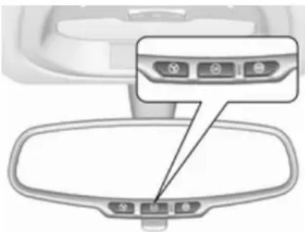
Privacy button
Press and hold Ⓧ until a message is heard to activate or deactivate the transmission of the vehicle location.
Press Ⓧ to answer a call or to end a call to an advisor.
Press Ⓧ to access the Wi-Fi settings.
Service button
Press Ⓞ to establish a connection to an advisor.
SOS button
Press ☺ to establish a priority emergency connection to a specially trained emergency advisor.
Status LED
Green: The system is ready.
Green flashing: The system is on a call.
Red: A problem arose.
Off: System is in standby mode.
Red / green flashing for a short period of time: Transmission of the vehicle location has been deactivated.
OnStar services
General services
If you need any information concerning e.g. opening hours, points of interest and destinations or if you need any support e.g. in the case of a vehicle breakdown, a flat tyre and empty fuel tank, press Ⓞ to establish a connection to an advisor.
Emergency services
In the case of an emergency situation, press 📋 and talk to an advisor. The advisor then contacts emergency or assistance service providers and directs them to your vehicle.
In the case of an accident with activation of airbags or belt tensioners, an automatic emergency call is established. The advisor is immediately connected to your vehicle to see whether help is needed.
Wi-Fi hotspot
The Wi-Fi hotspot of the vehicle provides internet connectivity with a maximum speed of 4G/LTE.
Notice
The Wi-Fi hotspot functionality is not available for all markets.
Up to seven devices may be connected.
To connect a mobile device with the Wi-Fi hotspot:
- Press Ⓞ and then select Wi-Fi settings on the Info-Display. The settings displayed include the Wi-Fi hotspot name (SSID), password and connection type.
- Start a Wi-Fi network search on your mobile device.
- Select your vehicle hotspot (SSID) when listed.
- When prompted, enter the password on your mobile device.
Notice
To change the SSID or password, press Ⓞ and talk to an advisor or log in to your account.
To switch off the Wi-Fi hotspot functionality, press Ⓞ to call an advisor.
86 Instruments and controls
Smartphone app
With the My Vauxhall smartphone app, some vehicle functions can be operated remotely.
The following functions are available:
- Lock or unlock vehicle.
- Honk horn or flash lights.
- Check fuel level, engine oil life and tyre pressure (only with tyre pressure monitoring system).
- Send navigation destination to the vehicle, if equipped with a built-in navigation system.
- Locate vehicle on a map.
- Manage Wi-Fi settings.
To operate these functions, download the app from Apple's App Store or Google Play Store.
Remote control
If desired, use any phone to call an advisor, who can remotely operate specific vehicle functions. Find the respective OnStar phone number on our country-specific website.
The following functions are available:
- Lock or unlock vehicle.
- Provide information on the vehicle location.
• Honk horn or flash lights.
Stolen vehicle assistance
If the vehicle is stolen, report the theft to the authorities and request OnStar stolen vehicle assistance. Use any phone to call an advisor. Find the respective OnStar phone number on our country-specific website.
OnStar can provide support in locating and recovering the vehicle.
Theft alert
When the anti-theft alarm system is triggered, a notification is sent to OnStar. You are then informed about this event by text message or email.
Restart prevention
By sending remote signals, OnStar can prevent the vehicle from restarting once it has been turned off.
On-demand diagnostics
At any time e.g. if the vehicle displays a vehicle message, press Ⓞ to contact an advisor and ask to complete a real-time diagnostic check to directly determine the issue.
Depending on the results, the advisor will provide further support.
Diagnostic report
The vehicle automatically transmits diagnostic data to OnStar which sends a monthly email report to you and your preferred workshop.
Notice
The workshop notification function can be disabled in your account.
The report contains the status of key operating systems of the vehicle like engine, transmission, airbags, ABS, and other major systems. It also provides information on possible maintenance items and tyre pressure (only with tyre pressure monitoring system).
To look at the information in greater detail, select the link within the email and log in to your account.
Destination download
A desired destination can be directly downloaded to the navigation system.
Press ☑ to call an advisor and describe the destination or point of interest.
The advisor can look up any address or point of interest and directly send the destination to the built-in navigation system.
OnStar settings
OnStar PIN
To have full access to all OnStar services, a four-digit PIN is required. The PIN has to be personalised when first talking to an advisor.
To change the PIN, press Ⓞ to call an advisor.
Account data
An OnStar subscriber has an account where all the data is stored. To request a change of the account information, press ® and talk to an advisor or log in to your account.
If the OnStar service is used on another vehicle, press Ⓞ and request that the account be transferred to the new vehicle.
Notice
In any case, if the vehicle is disposed of, sold or otherwise transferred, immediately inform OnStar about the changes and terminate the OnStar service on this vehicle.
Vehicle location
The vehicle location is transmitted to OnStar when service is requested or triggered. A message on the Info-Display informs about this transmission.
To activate or deactivate the transmission of the vehicle location, press and hold Ⓞ until an audio message is heard.
The deactivation is indicated by the status light flashing red and green for a short period of time and each time the vehicle is started.
Notice
If the transmission of the vehicle location is deactivated, some services are no longer available.
Notice
The vehicle location always remains accessible to OnStar in the case of an emergency.
Find the privacy policy in your account.
Software updates
OnStar may remotely carry out software updates without further notice or consent. These updates are to enhance or maintain safety and security or the operation of the vehicle.
These updates may concern privacy issues. Find the privacy policy in your account.
88 Lighting
Lighting
Exterior lighting 88
Light switch 88
High beam 88
Headlight flash 88
Headlight range adjustment ..... 89
Headlights when driving abroad 89
Daytime running lights 89
Cornering lights 89
Hazard warning flashers 89
Turn and lane-change signals ... 90
Front fog lights 90
Rear fog light 90
Parking lights 91
Reversing lights 91
Misted light covers 91
Interior lighting 91
Instrument panel illumination control 91
Interior lights 92
Reading lights 92
Lighting features 93
Exit lighting 93
Battery discharge protection ..... 93
Exterior lighting
Light switch

Turn light switch:
0 : lights off
: sidelights
≡D : headlights
Control indicator 72.
Tail lights
Tail lights are illuminated together with headlights and sidelights.
High beam
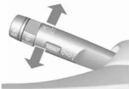
To switch from low to high beam, push lever.
To switch to low beam, push lever again or pull.
Headlight flash
To activate the headlight flash, pull lever.
Headlight range adjustment
Manual headlight range adjustment

To adapt headlight range to the vehicle load to prevent dazzling: turn thumb wheel ⚠️ to required position.
0 : front seats occupied
1 : all seats occupied
2 : all seats occupied and load compartment laden
3 : driver's seat occupied and load compartment laden
Headlights when driving abroad
Headlight aim has been preset and should need no further adjustment. When driving in countries with opposite hand traffic, it is not necessary to adjust the headlights.
Daytime running lights
Daytime running light increases visibility of the vehicle during daylight.
They are switched on automatically when ignition is on.
Cornering lights

On tight bends or when turning off, depending on the steering angle or the indicator light signal, an additional left or right reflector is switched on
which illuminates the road in the direction of travel. It is activated up to a speed of 25 mph.
Hazard warning flashers

Operated by pressing △.
In the event of an accident with airbag deployment, the hazard warning flashers are activated automatically.
90 Lighting
Turn and lane-change signals
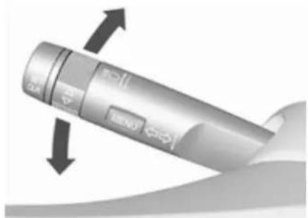
lever up : right turn signal lever down : left turn signal
If the lever is moved past the resistance point, the turn signal is switched on constantly. When the steering wheel moves back, the turn signal is automatically deactivated.
For three flashes, e.g., when changing lanes, press the lever until resistance is felt and then release.
Move the lever to the resistance point and hold for longer indication.
Switch the turn signal off manually by moving the lever to its original position.
Front fog lights
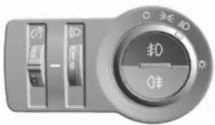
Operated by pressing #D.
Rear fog light

Operated by pressing Ⓓ.
Light switch in position ≈: Rear fog light can only be switched on with front fog lights.
Parking lights

When the vehicle is parked, the parking lights on one side can be activated:
- Switch off the ignition.
- Move the turn signal lever all the way up (right parking lights) or down (left parking lights).
Confirmed by an acoustic signal and the corresponding turn signal control indicator.
Reversing lights
The reversing light comes on when the ignition is on and reverse gear is selected.
Misted light covers
The inside of the light housing may mist up briefly in poor, wet and cold weather conditions, in heavy rain or after washing. The mist disappears quickly by itself; to help switch on the headlights.
Interior lighting
Instrument panel illumination control
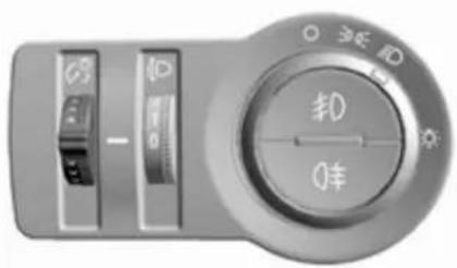
Brightness of the following lights can be adjusted when the exterior lights are on:
• instrument panel illumination
- Info-Display
- illuminated switches and operation elements
Turn thumb wheel ⚙️ and hold until the desired brightness is obtained.
92 Lighting
Interior lights
When opening a door, the courtesy light automatically switches on and then off after a delay.
When exterior lighting has been on, courtesy light will turn on when ignition is switched off.
Notice
In the event of an accident with airbag deployment, the courtesy lights are turned on automatically.
Courtesy light

Operate rocker switch:
centre : automatic switching on position ☐ when opening a door. Turns off after a delay.
press : permanently on press : permanently off
Reading lights
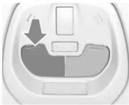

Operated by pressing the buttons in front.
Dome light
Spotlight incorporated in the interior lighting comes on when headlights are switched on.
Dome light illuminates gear shifting console indirectly.
Lighting features
Exit lighting
Path lighting
Headlights, tail lights and number plate lights illuminate the surrounding area for an adjustable time after leaving the vehicle.
Activating

- Switch off the ignition.
- Remove the ignition key.
-
Open driver's door.
-
Pull the turn signal lever.
- Close the driver's door.
If the driver's door is not closed the lights switch off after two minutes.
Exit lighting is switched off immediately if the turn signal lever is pulled while the driver's door is open.
Activation, deactivation and duration of this function can be changed in the Info-Display. Vehicle personalisation ⇒ 82.
The settings can be saved for the key being used ➔ 21.
Battery discharge protection
Switching off electric lights
To prevent discharge of the vehicle battery when the ignition is switched off, some interior lights are switched off automatically after some time.
Climate control
Climate control systems ..... 94
Heating and ventilation system . 94
Air conditioning system 95
Electronic climate control system 97
Air vents 100
Adjustable air vents 100
Fixed air vents 101
Maintenance 101
Air intake 101
Pollen filter 101
Air conditioning regular operation 101
Service 102
Climate control systems Heating and ventilation system

Controls for:
- temperature
- fan speed
- air distribution
• demisting and defrosting - air recirculation
Heated rear window ➕ 29.
Heated seats ↗ 34.
Heated steering wheel ⚙ 57.
Temperature
Adjust the temperature by turning the temperature control.
red : warm
blue : cold
Heating will not be fully effective until the engine has reached normal operating temperature.
Fan speed
Adjust the air flow by switching the fan to the desired speed.
Air distribution
: to head area via adjustable air vents
: to head area and foot well
: to foot well, with a small amount of air being directed to windscreen and front door windows
: to windscreen and foot well, with a small amount of air being directed to front door windows
: to windscreen and front door windows
Intermediate settings are possible.
Demisting and defrosting the windows
- Set air distribution control to 📂.
- Set temperature control to warmest level.
- Set fan speed to highest speed.
- Switch on heated rear window 📄.
- Open side air vents as required and direct them towards door windows.
- For simultaneous warming of the foot well, set air distribution control to ↓.
Air conditioning system

Controls for:
- temperature
- fan speed
- air distribution
A/C : cooling
: air recirculation
: heated rear window
Heated rear window ➔ 29.
Heated seats ↗ 34.
Heated steering wheel ⚙ ➔ 57.
Temperature
Adjust the temperature by turning the temperature control.
red : warm
blue : cold
Heating will not be fully effective until the engine has reached normal operating temperature.
Fan speed
Adjust the air flow by switching the fan to the desired speed.
Air distribution
: to head area via adjustable air vents
: to head area and foot well
: to foot well, with a small amount of air being directed to windscreen and front door windows
: to windscreen and foot well, with a small amount of air being directed to front door windows
: to windscreen and front door windows (air conditioning is activated in the background to help preventing windows from fogging)
Intermediate settings are possible.
Cooling A/C
Press A/C to switch on cooling. The LED in the button illuminates to indicate activation. Cooling is only functional when the engine is running and climate control fan is switched on.
Press A/C again to switch off cooling.
The air conditioning system cools and dehumidifies (dries) as soon as the outside temperature is slightly above the freezing point. Therefore condensation may form and drip from under the vehicle.
If no cooling or drying is required, switch off the cooling system for fuel saving reasons.
Activated cooling may inhibit Autostops.
Stop-start system ↩ 106.
Air recirculation system
Press 📊 to activate air recirculation mode. The LED in the button illuminates to indicate activation.
Press 📄 again to deactivate air recirculation mode.

Warning
Driving with recirculation mode for a prolonged period of time can make you sleepy. Periodically turn to the outside air mode for fresh air.
The exchange of fresh air is reduced in air recirculation mode. In operation without cooling the air humidity increases, so the windows may mist up. The quality of the passenger compartment air deteriorates, which may cause the vehicle occupants to feel drowsy.
In warm and very humid ambient air conditions, the windscreen may mist up from outside, when cold air is directed towards it. If windscreen mists up from outside, activate windscreen wiper and deactivate 📌.
Maximum cooling
Briefly open the windows so that hot air can disperse quickly.
- Switch on cooling A/C.
- Switch on Air recirculation system 📄.
- Set temperature control to coldest level.
- Set fan speed to highest level.
- Set air distribution control to ↗.
- Open all vents.
Demisting and defrosting the windows 🌐
- Set air distribution control to 📌.
- Set temperature control to warmest level.
- Set fan speed to highest level.
- Switch on heated rear window 📄.
- Open side air vents as required and direct them towards the door windows.
When is switched on, A/C operates and air recirculation mode will be fixed to outside air mode regardless of indicator status.
Notice
If 📌 is pressed while the engine is running, an Autostop will be inhibited until 📌 is pressed again.
If 📌 is pressed while the engine is in an Autostop, the engine will restart automatically.
Stop-start system ↩ 106.
Electronic climate control system

Controls for:
- temperature
- air distribution
- fan speed
A/C : cooling
: demisting and defrosting

: heated rear window
Heated rear window ➔ 29.
Heated seats ↗ 34.
Heated steering wheel ⚙ 57.
Climate control settings are shown on the Info-Display. Setting modifications are briefly popped-up, superimposed over the currently displayed menu.
The electronic climate control system is only fully operational when the engine is running.
Heating will not be fully effective until the engine has reached normal operating temperature.
Automatic mode AUTO
The system automatically controls the fan speed, air delivery, air conditioning, and recirculation in order to heat or cool the vehicle to the desired temperature.
When the AUTO indicator light is on, the system is in full automatic operation.
If the air delivery mode, fan speed, recirculation, or air conditioning setting is adjusted, the AUTO indicator turns off.
To improve fuel efficiency and to cool the vehicle faster, recirculation may be automatically selected in warm
weather. The recirculation light will not come on. Press 📄 to select recirculation; press it again to select outside air.
To turn off the system, press power ⏻.
Basic setting for maximum comfort:
- Press AUTO. The LED in the button illuminates to indicate activation.
- Open all air vents to allow optimised air distribution in Automatic mode.
- Set the preselected temperature. Recommended temperature is 22 °C.
Temperature preselection
Set temperature to the desired value. It is indicated on the display in the temperature control.
For reasons of comfort, change temperature only in small increments.
If the minimum temperature Lo is set, the climate control system runs at maximum cooling, if cooling A/C is active.
If the maximum temperature Hi is set, the climate control system runs at maximum heating.
Recommended temperature is 22 °C.
Notice
If A/C is switched on, reducing the set cabin temperature can cause the engine to restart from an Autostop or inhibit an Autostop.
Stop-start system ↩ 106.
Demisting and defrosting the windows 🌐
- Press 📋. The LED in the button illuminates to indicate activation.
- Temperature and air distribution are set automatically and the fan runs at high speed.
- Switch on heated rear window 📄.
- To return to previous mode: press 📋. To return to Automatic mode: press AUTO.
Notice
If is pressed while the engine is running, an Autostop will be inhibited until is pressed again.
If 📌 is pressed while the engine is in an Autostop, the engine will restart automatically.
Stop-start system ↩ 106.
Air recirculation system
Press 📄 to activate air recirculation mode. The LED in the button illuminates to indicate activation.
Press 📄 again to deactivate air recirculation mode.
⚠ Warning
Driving with recirculation mode for a prolonged period of time can make you sleepy. Periodically turn to the outside air mode for fresh air.
The exchange of fresh air is reduced in air recirculation mode. In operation without cooling the air humidity increases, so the
windows may mist up. The quality of the passenger compartment air deteriorates, which may cause the vehicle occupants to feel drowsy.
In warm and very humid ambient air conditions, the windscreen may mist up from outside, when cold air is directed towards it. If windscreen mists up from outside, activate windscreen wiper and deactivate 📌.
Manual settings
Climate control system settings can be changed by activating the buttons and rotary knobs as follows. Changing a setting will deactivate Automatic mode.
Climate control 99
Fan speed
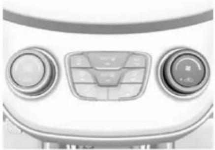
Adjust the air flow by switching the fan to the desired speed. The selected fan speed is indicated by the number of segments in the display. If the fan is switched off the air conditioning is also deactivated.
To return to Automatic mode: Press AUTO.
Air distribution

Press appropriate button for desired adjustment. Activation is indicated by the LED in the button.
: to head area
→: to head area and foot well
: to foot well, with a small amount of air being directed to windscreen and front door windows
: to windscreen and foot well, with a small amount of air being directed to front door windows
: to windscreen and front door windows (air conditioning is activated in the background to help preventing windows from fogging)
To return to Automatic mode: Press AUTO.
Cooling A/C

Press A/C to switch on cooling. The LED in the button illuminates to indicate activation. Cooling is only functional when the engine is running and climate control fan is switched on.
100 Climate control
Press A/C again to switch off cooling.
The air conditioning system cools and dehumidifies (dries) as soon as the outside temperature is slightly above the freezing point. Therefore condensation may form and drip from under the vehicle.
If no cooling or drying is required, switch off the cooling system for fuel saving reasons.
Activated cooling might inhibit Autostops.
Stop-start system ↩ 106.
Air recirculation mode
Press 📄 to activate air recirculation mode. The LED in the button illuminates to indicate activation.
Press 📄 again to deactivate air recirculation mode.

Warning
The exchange of fresh air is reduced in air recirculation mode. In operation without cooling, the air humidity increases, so the
windows may mist up from inside. The quality of the passenger compartment air deteriorates, which may cause the vehicle occupants to feel drowsy.
In warm and very humid ambient air conditions, the windscreen may mist up from outside when cold air is directed towards it. If windscreen mists up from outside, activate windscreen wiper.
Maximum cooling
Briefly open the windows so that hot air can disperse quickly.
- Switch on cooling A/C.
- Switch on Air recirculation system 📄.
- Set temperature control to coldest level.
- Set fan speed to highest level.
- Set air distribution control to ↗.
- Open all vents.
Air vents
Adjustable air vents
At least one air vent must be open while the cooling is on.

Direct the flow of air by tilting and swivelling the slats.

Warning
Do not attach any objects to the slats of the air vents. Risk of damage and injury in case of an accident.
Fixed air vents
Additional air vents are located beneath the windscreen and door windows and in the foot wells.
Maintenance
Air intake

The air intake in front of the windscreen in the engine compartment must be kept clear to allow air intake. Remove any leaves, dirt or snow.
Pollen filter
The pollen filter cleans dust, soot, pollen and spores from the air entering the vehicle through the air intake.
The filter should be replaced as part of routine scheduled maintenance.
Caution
More frequent maintenance of the passenger compartment air filter is required if the driving circumstances are dusty roads, air pollution areas, and frequent unpaved roads.
The filter efficiency is decreased and the bronchus is badly affected.
Air conditioning regular operation
In order to ensure continuously efficient performance, cooling must be operated for a few minutes once a month, irrespective of the weather and time of year. Operation with cooling is not possible when the outside temperature is too low.
102 Climate control
Service
For optimal cooling performance, it is recommended to annually check the climate control system, starting three years after initial vehicle registration, including:
• functionality and pressure test
- heating functionality
- leakage check
- check of drive belts
• cleaning of condenser and evaporator drainage
• performance check
Driving and operating
Driving hints 103
Control of the vehicle 103
Steering 104
Starting and operating 104
New vehicle running-in 104
Ignition switch positions ..... 104
Retained power off 105
Starting the engine 105
Overrun cut-off 106
Stop-start system 106
Parking 109
Engine exhaust 110
Catalytic converter 110
Manual transmission 110
Manual transmission automated 111
Transmission display 111
Starting the engine 111
Selector lever 112
Manual mode 113
Electronic driving programmes 113
Fault 113
Brakes 114
Antilock brake system 114
Parking brake 115
Brake assist 115
Hill start assist 115
Ride control systems 116
Traction Control system 116
Electronic Stability Control ..... 117
City mode 118
Driver assistance systems ..... 119
Cruise control 119
Speed limiter 121
Parking assist 122
Lane departure warning ..... 123
Fuel 124
Fuel for petrol engines 124
Fuel for liquid gas operation .... 125
Refuelling 127
Fuel consumption - CO 2 - Emissions 130
Driving hints
Control of the vehicle
Never coast with engine not running
Many systems will not function in this situation (e.g. brake servo unit, power steering). Driving in this manner is a danger to yourself and others.
All systems function during an Autostop.
Stop-start system ↩ 106.
Idle boost
If charging of the vehicle battery is required due to battery condition, the power output of the generator must be increased. This will be achieved by an idle boost which may be audible.
A message appears in the Driver Information Centre.
Pedals
To ensure the pedal travel is uninhibited, there must be no mats in the area of the pedals.
104 Driving and operating
Use only floor mats, which fit properly and are fixed by the retainers on the driver side.
Driving downhill
Engage a gear when driving downhill to ensure that sufficient brake pressure is available.
Steering
If power steering assist is lost because the engine stops or due to a system malfunction, the vehicle can be steered but may require increased effort.
Control indicator ⬤! ➔ 70.
Caution
Vehicle equipped with electric power steering:
If the steering wheel is turned until it reaches the end of its travel and is held against that position for an extended period of time, power steering assistance may be reduced.
If the steering assistance is used for an extended period of time, power assistance may be reduced.
Power steering assistance should return back to normal when the system has cooled down.
Starting and operating
New vehicle running-in
Do not brake unnecessarily hard for the first few journeys.
During the first drive, smoke may occur because of wax and oil evaporating off the exhaust system.
Park the vehicle in the open for a while after the first drive and avoid inhaling the fumes.
During the running-in period, fuel and engine oil consumption may be higher.
Autostop may be inhibited to allow for charging of the vehicle battery.
Ignition switch positions
Turn key:
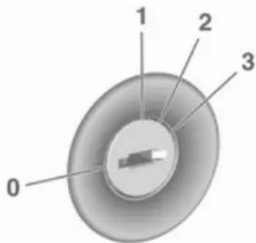
0 : ignition off: Some functions remain active until key is removed or driver's door is opened, provided the ignition was on previously
1: accessory power mode: Steering wheel lock released, some electrical functions are operable, ignition is off
2: ignition on power mode: Ignition is on. Control indicators illuminate and most electrical functions are operable
3 : engine start: Release key after starting procedure begins
Steering wheel lock
Remove key from ignition switch and turn steering wheel until it engages.
Retained power off
The following electronic systems are operable until the driver's door is opened or at the latest for ten minutes after the ignition is switched off:
- power windows
- power outlets
- power sunroof
Power to the Infotainment system will continue to operate for 30 minutes or until the key is removed from the ignition switch, regardless of whether any door is opened.
Starting the engine

Turn key to position 1 to release the steering wheel lock.
Manual transmission: operate clutch and brake pedal.
Manual transmission automated: operate brake pedal.
Do not operate the accelerator pedal.
Turn key briefly to position 3 and release: an automatic procedure operates the starter after a brief delay, until the engine is running. See "Automatic Starter Control".
106 Driving and operating
Before restarting or to switch off the engine, turn the key back to position 0.
During an Autostop, the engine can be started by depressing the clutch pedal.
Starting the vehicle at low temperatures
The start of the engine without additional heaters is possible down to -30 °C.
Required is an engine oil with the correct viscosity, the correct fuel, performed services and a sufficiently charged vehicle battery.
Automatic starter control
This function controls the engine starting procedure. The driver does not need to hold the key in position 3. Once applied, the system will go on starting automatically until the engine is running. Because of the checking procedure, the engine starts running after a short delay.
Possible reasons for a non-starting engine:
- clutch pedal not operated (manual transmission)
- brake pedal not operated (manual transmission automated)
- timeout occurred
Turbo engine warm-up
Upon start-up, engine available torque may be limited for a short time, especially when the engine temperature is cold. The limitation is to allow the lubrication system to fully protect the engine.
Overrun cut-off
The fuel supply is automatically cut-off during overrun, i.e. when the vehicle is driven with a gear engaged but accelerator is released.
Stop-start system
The stop-start system helps to save fuel and to reduce the exhaust emissions. When conditions allow, it
switches off the engine as soon as the vehicle is at a low speed or at a standstill, e.g. at a traffic light or in a traffic jam.
On vehicles with manual transmission, the engine is started automatically as soon as the clutch is depressed.
On vehicles with manual transmission automated, the engine is started automatically as soon as the brake pedal is released.
A vehicle battery sensor ensures that an Autostop is only performed if the vehicle battery is sufficiently charged for a restart.
Activation
The stop-start system is available as soon as the engine is started, the vehicle starts-off and the conditions as stated below in this section are fulfilled.
Deactivation
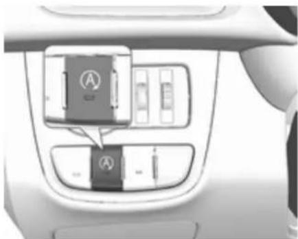
Deactivate the stop-start system manually by pressing Ⓐ. The deactivation is indicated when the LED in the button extinguishes.
Autostop
Vehicles with manual transmission If the vehicle is at a low speed or at a standstill, activate an Autostop as follows:
- Depress the clutch pedal.
- Set the lever in neutral.
- Release the clutch pedal.
The engine will be switched off while the ignition stays on.
Vehicles with manual transmission automated
If the vehicle is at a standstill with the brake pedal depressed, Autostop is activated automatically.
The engine will be switched off while the ignition stays on.
The stop-start system will be disabled on inclines of 15% or more.
Indication
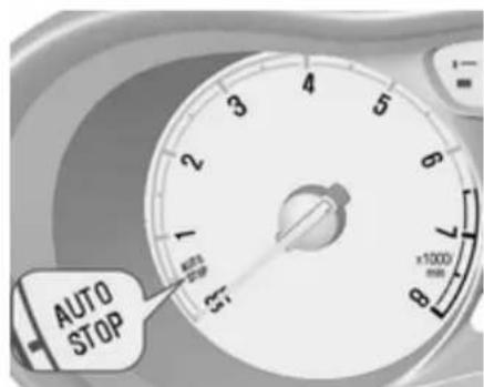
An Autostop is indicated by the needle at the AUTOSTOP position in the tachometer.
During an Autostop, the heating and brake performance will be maintained.
Conditions for an Autostop
The stop-start system checks if each of the following conditions is fulfilled:
- The stop-start system is not manually deactivated.
• The bonnet is fully closed. - The driver's door is closed or the driver's seat belt is fastened.
- The vehicle battery is sufficiently charged and in good condition.
• The engine is warmed-up. - The engine coolant temperature is not too high.
- The engine exhaust temperature is not too high, e.g. after driving with high engine load.
- The ambient temperature is above -5°C .
• The climate control system allows an Autostop.
108 Driving and operating
- The brake vacuum is sufficient.
- The vehicle was driven at least at walking speed since the last Autostop.
Otherwise an Autostop will be inhibited.
Certain settings of the climate control system may inhibit an Autostop. See "Climate control" chapter for further information 97.
Immediately after motorway driving an Autostop may be inhibited.
New vehicle running-in ➔ 104.
Vehicle battery discharge protection To ensure reliable engine restarts, several vehicle battery discharge protection features are implemented as part of the stop-start system.
Power saving measures
During an Autostop, several electrical features, e.g., the rear window heating, are disabled or switched into a power saving mode. The fan speed of the climate control system is reduced to save power.
Restart of the engine by the driver
Vehicles with manual transmission Depress the clutch pedal to restart the engine.
If the selector lever is shifted out of neutral before depressing the clutch pedal first, control indicator ↗ illuminates or is shown as a symbol in the Driver Information Centre.
Control indicator ↘ 69.
Vehicles with manual transmission automated
Release the brake pedal or move selector lever out of D to restart the engine.
Restart of the engine by the stop-start system
The selector lever must be in neutral to enable an automatic restart.
If one of the following conditions occurs during an Autostop, the engine will be restarted automatically by the stop-start system:
- The stop-start system is manually deactivated.
-
The bonnet is opened.
-
The driver's seat belt is unfastened and the driver's door is opened.
- The engine temperature is too low.
- The charging level of the vehicle battery is below a defined level.
- The brake vacuum is not sufficient.
- The vehicle is driven at least at walking speed.
- The climate control system requests an engine start.
- The air conditioning is manually switched on.
If the bonnet is not fully closed, a warning message is displayed in the Driver Information Centre.
If an electrical accessory, e.g. a portable CD player, is connected to the power outlet, a brief power drop during restart might be noticeable.
Parking
⚠ Warning
- Do not park the vehicle on an easily ignitable surface. The high temperature of the exhaust system could ignite the surface.
- Always apply the parking brake. Activate the manual parking brake without pressing the release button. Apply as firmly as possible on a downhill slope or uphill slope. Depress brake pedal at the same time to reduce operating force.
- Switch off the engine.
- If the vehicle is on a level surface or uphill slope, engage first gear before removing the ignition key. On an uphill slope, turn the front wheels away from the kerb.
If the vehicle is on a downhill slope, engage reverse gear before removing the ignition
key. Turn the front wheels towards the kerb.
- Close the windows and the sunroof.
- Remove the ignition key from the ignition switch. Turn the steering wheel until the steering wheel lock is felt to engage.
For vehicles with manual transmission automated, the key can only be removed from the ignition switch when the parking brake is applied.
- Lock the vehicle.
- Activate the anti-theft alarm system.
- The engine cooling fans may run after the engine has been switched off 133.
Caution
After running at high engine speeds or with high engine loads, operate the engine briefly at a low
load or run in neutral for approx. 30 seconds before switching off, in order to protect the turbocharger.
Notice
In the event of an accident with airbag deployment, the engine is switched off automatically if the vehicle comes to a standstill within a certain time.
Engine exhaust

Danger
Engine exhaust gases contain poisonous carbon monoxide, which is colourless and odourless and could be fatal if inhaled.
If exhaust gases enter the interior of the vehicle, open the windows. Have the cause of the fault rectified by a workshop.
Avoid driving with an open load compartment, otherwise exhaust gases could enter the vehicle.
Catalytic converter
The catalytic converter reduces the amount of harmful substances in the exhaust gases.
Caution
Fuel grades other than those listed on pages ⇔ 124, ⇔ 177 could damage the catalytic converter or electronic components.
Unburnt petrol will overheat and damage the catalytic converter. Therefore avoid excessive use of the starter, running the fuel tank dry and starting the engine by pushing or towing.
In the event of misfiring, uneven engine running, a reduction in engine performance or other unusual problems, have the cause of the fault rectified by a workshop as soon as possible. In an emergency, driving can be continued for a short period, keeping vehicle speed and engine speed low.
Manual transmission

To engage reverse, depress the clutch pedal and engage the reverse gear.
If the gear does not engage, set the lever to neutral, release the clutch pedal and depress again; then repeat gear selection.
Do not slip the clutch unnecessarily.
When operating, depress the clutch pedal completely. Do not use the pedal as a foot rest.
Caution
It is not advisable to drive with the hand resting on the selector lever.
Upshift indication ⇒ 70.
Stop-start system ↩ 106.
Manual transmission automated
The automated manual transmission permits manual gearshifting (manual mode) or automatic gearshifting (automatic mode), both with automatic clutch control.
Manual shifting is possible by tapping the selector lever in manual mode.
Notice
When unlocking or opening a vehicle door, a sound may be audible caused by the hydraulic system.
Transmission display

In automatic mode, the driving programme is indicated by D in the Driver Information Centre.
In manual mode, M and the number of the selected gear is indicated.
R indicates reverse gear.
N indicates neutral.
Starting the engine
To start the engine, depress the brake pedal, if transmission is not in position N.
112 Driving and operating
Transmission automatically shifts to N upon starting. There may be a slight delay.
Starting is not possible if all brake lights fail.
Selector lever

Always move the selector lever in the appropriate direction as far as it will go. Upon release, it automatically returns to the centre position.
N : neutral position
D/M : switch between automatic (D) and manual (M) shift mode. The transmission display shows either D or M with the selected gear
+ : upshifting in manual mode
— : downshifting in manual mode
R : reverse gear. Engage only when vehicle is stationary
If selector lever is moved from R to the left, D is directly engaged.
If selector lever is moved from D to
+ or -, manual mode M is selected and the transmission shifts.
Starting off
Depress the brake pedal and move the selector lever to D/M or R. If D is selected, transmission is in automatic mode and first gear is engaged. If R is selected, reverse gear is engaged. The vehicle starts to move when the brake pedal is released.
To start off immediately without depressing the brake pedal, move the selector lever to D or R. D or R will flash for a short time in the Driver
Information Centre. Accelerate as long as D or R flashes. The selected gear is engaged and the vehicle starts moving.
If the accelerator pedal is not depressed as long as D or R are flashing in the Driver Information Centre, no gear is engaged.
Stopping the vehicle
In D, first gear is engaged and the clutch is released when the vehicle is stopped. In R, reverse gear remains engaged.
Engine braking
Automatic mode
When driving downhill, the manual transmission automated does not shift into higher gears until a fairly high engine speed has been reached. It shifts down in good time when braking.
Manual mode
To utilise the engine braking effect, select a lower gear in good time when driving downhill. Changing into manual mode is only possible while the engine is running.
Rocking the vehicle
Rocking the vehicle is only permissible if the vehicle is stuck in sand, mud or snow. Move the selector lever between R and D in a repeat pattern. Do not race the engine and avoid sudden acceleration.
Parking
The most recently engaged gear (see transmission display) remains engaged when switching off ignition. With N, no gear is engaged.
Therefore always apply the parking brake when switching off ignition. If parking brake is not applied, P flashes in the transmission display and the key cannot be removed from the ignition switch. P stops flashing in the transmission display as soon as the parking brake is slightly applied.
When the ignition is switched off, the transmission no longer responds to movement of the selector lever.
Tyre pressure monitoring system
To start the sensor matching process of the tyre pressure monitoring system, the selector lever must be moved and held in position N for five seconds. P illuminates in the transmission display to indicate that the sensor matching process can be started.
Tyre pressure monitoring system 151.
Manual mode
If a higher gear is selected when the engine speed is too low, or a lower gear when the speed is too high, the shift is not executed. This prevents the engine from running at too low or too high an engine speed. M and the number of the selected gear will be flashed, then the current gear is displayed again..
If engine speed is too low, the transmission automatically shifts to a lower gear.
When + or - is selected in automatic mode, the transmission switches to manual mode and shifts accordingly.
Gear shift indication
The symbol ▲ with a number alongside it, is indicated when gearshifting is recommended for fuel saving reasons.
Shift indication appears only in manual mode.
Electronic driving programmes
The adaptive programme tailors gearshifting to the driving conditions, e.g. greater load or gradients.
Fault
To prevent damage to the manual transmission automated, the clutch is engaged automatically at high clutch temperatures.
114 Driving and operating
In the event of a fault, control indicator
illuminates. Additionally, a warning message is displayed in the Driver Information Centre. Vehicle messages 79.
Continued driving is restricted or not possible, depending on the fault.
Have the cause of the fault remedied by a workshop.
Brakes
The brake system comprises two independent brake circuits.
If a brake circuit fails, the vehicle can still be braked using the other brake circuit. However, braking effect is achieved only when the brake pedal is depressed firmly. Considerably more force is needed for this. The braking distance is extended. Seek the assistance of a workshop before continuing the journey.
When the engine is not running, the support of the brake servo unit disappears once the brake pedal has been depressed once or twice.
Braking effect is not reduced, but braking requires significantly greater force. It is especially important to bear this in mind when being towed.
Control indicator Ⓔ 69.
Antilock brake system
Antilock brake system (ABS) prevents the wheels from locking.
ABS starts to regulate brake pressure as soon as a wheel shows a tendency to lock. The vehicle remains steerable, even during hard braking.
ABS control is made apparent through a pulse in the brake pedal and the noise of the regulation process.
For optimum braking, keep the brake pedal fully depressed throughout the braking process, despite the fact that the pedal is pulsating. Do not reduce the pressure on the pedal.
After starting-off the system performs a self-test which may be audible.
Control indicator (ABS) 70.
Adaptive brake light
During full braking, all three brake lights flash for the duration of ABS control.
Fault
Warning
If there is a fault in the ABS, the wheels may be liable to lock due to braking that is heavier than normal. The advantages of ABS are no longer available. During hard braking, the vehicle can no longer be steered and may swerve.
Have the cause of the fault remedied by a workshop.
Parking brake
Manual parking brake
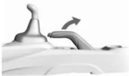
Warning
Always apply parking brake firmly without operating the release button, and apply as firmly as possible on a downhill or uphill slope.
To release the parking brake, pull the lever up slightly, press the release button and fully lower the lever.
To reduce the operating forces of the parking brake, depress the brake pedal at the same time.
Control indicator Ⓙ 69.
Brake assist
If the brake pedal is depressed quickly and forcefully, maximum brake force is automatically applied (full braking).
Maintain steady pressure on the brake pedal for as long as full braking is required. Maximum brake force is automatically reduced when the brake pedal is released.
Hill start assist
The system helps prevent unintended movement when driving away on inclines.
When releasing the brake pedal after stopping on an incline, the brakes remain on for a further two seconds. The brakes release automatically as
116 Driving and operating
soon as the vehicle begins to accelerate or the two seconds holding time is over.
The hill start assist is not active during an Autostop.
Ride control systems
Traction Control system
The Traction Control system (TC) is a component of the Electronic Stability Control (ESC).
TC improves driving stability when necessary, regardless of the type of road surface or tyre grip, by preventing the drive wheels from spinning.
As soon as the drive wheels start to spin, engine output is reduced and the wheel spinning the most is braked individually. This considerably improves the driving stability of the vehicle on slippery road surfaces.
TC is operational after each engine start as soon as the control indicator extinguishes.
When TC operates ✉ flashes.
⚠ Warning
Do not let this special safety feature tempt you into taking risks when driving.
Adapt speed to the road conditions.
Deactivation

TC can be switched off when spinning of drive wheels is required: press briefly.

Control indicator Ⓤ illuminates.
When TC is deactivated, ESC remains active.
TC is reactivated by pressing 1/2 again. TC is also reactivated the next time the ignition is switched on.
Fault
If there is a fault in the system the control indicator ♂ illuminates continuously and a warning code appears in the Driver Information Centre. The system is not operational.
Have the cause of the fault remedied by a workshop.
Electronic Stability Control
Electronic Stability Control (ESC) improves driving stability when necessary, regardless of the type of road surface or tyre grip.
As soon as the vehicle starts to swerve (understeer/oversteer), engine output is reduced and the wheels are braked individually.
ESC operates in combination with the Traction Control system (TC). It prevents the drive wheels from spinning.
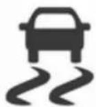
ESC is operational after each engine start as soon as the control indicator extinguishes.
When ESC operates flashes .
Warning
Do not let this special safety feature tempt you into taking risks when driving.
Adapt speed to the road conditions.
Control indicator ➡ 70.
Deactivation

For very high-performance driving ESC can be deactivated:
Press and hold 📄 for a minimum of five seconds. Control indicator 📄 illuminates.
118 Driving and operating
ESC is reactivated by pressing again. If the TC system was previously disabled, both TC and ESC are reactivated. ① and ② extinguish when TC and ESC are reactivated.
ESC is also reactivated the next time the ignition is switched on.
Fault
If there is a fault in the system, the control indicator ⚪ illuminates continuously and a warning code appears in the Driver Information Centre. The system is not operational.
Have the cause of the fault remedied by a workshop.
City mode
City mode is a feature which enables increased steering assistance during lower speed conditions, e.g. city traffic or parking. Steering assistance is increased for greater convenience.
Activation

Press ⚙ when engine is running. The system works from standstill up to 37 mph, and also in reverse gear. Above this speed, the system changes to normal mode. When activated, City mode engages automatically below 37 mph.
An illuminated LED in the City mode button indicates that the system is active and a message pops-up in the Driver Information Centre.
City mode remains active during an Autostop, but is only operational when the engine is running. Stop-start system 106.
Deactivation
Press 🔒. The LED in the button extinguishes.
Each time the engine is started, City mode is deactivated.
Overload
If the steering in City mode is heavily loaded, e.g. in long parking manoeuvres or heavy city traffic, the system is deactivated for overheat protection. Steering operates in normal mode until City mode activates automatically
Fault
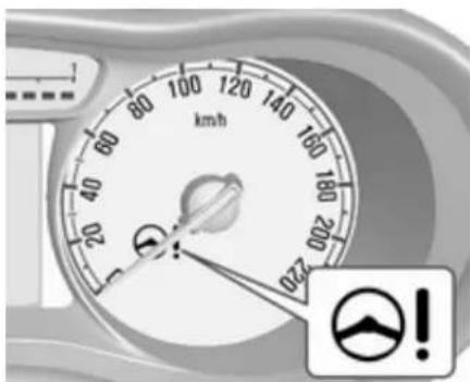
In the event of a fault in the system, control indicator ⬤! illuminates. Vehicle messages ➔ 79.
Driver assistance systems
Warning
Driver assistance systems are developed to support the driver and not to replace the driver's attention.
The driver accepts full responsibility when driving the vehicle.
When using driver assistance systems, always take care regarding the current traffic situation.
Cruise control
The cruise control can store and maintain speeds of approx. 15 mph to 105 mph. Deviations from the stored speeds may occur when driving uphill or downhill.
For safety reasons, the cruise control cannot be activated until the brake pedal has been operated once.
Activating in first gear is not possible.
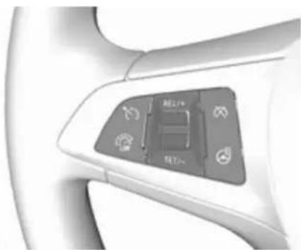
Do not use the cruise control if it is not advisable to maintain a constant speed.
On vehicles with manual transmission automated, cruise control can be activated in automatic mode and manual mode.
Control indicator ➕ 72.
Switching on

120 Driving and operating
Press ☑; control indicator ⚙ in instrument cluster illuminates white.
Activation
Accelerate to the desired speed and turn thumb wheel to SET/-, the current speed is stored and maintained. Control indicator ⚙ in instrument cluster illuminates green. Set speed is indicated on the display. Accelerator pedal can be released.
Vehicle speed can be increased by depressing the accelerator pedal. When the accelerator pedal is released, the previously stored speed is resumed.
Cruise control remains activated while gearshifting.
Increase speed
With cruise control active, hold thumb wheel turned to RES/+ or briefly turn to RES/+ repeatedly: speed increases continuously or in small increments.
Alternatively accelerate to the desired speed and store by turning to SET/-.

Reduce speed
With cruise control active, hold thumb wheel turned to SET/- or briefly turn to SET/- repeatedly: speed decreases continuously or in small increments.
Deactivation
Press ☒; control indicator ☑ in instrument cluster illuminates white. Cruise control is deactivated. Last stored speed remains in memory for later speed resume.
Automatic deactivation:
- Vehicle speed is below approx. 15 mph.
• The brake pedal is depressed. - The clutch pedal is depressed for a few seconds.
• The selector lever is in N.
• Engine speed is in a very low range. - The Traction Control system or Electronic Stability Control is operating.
Resume stored speed
Turn thumb wheel to RES/+ at a speed above 15 mph. The stored speed will be obtained.
Switching off
Press Ⓧ, control indicator Ⓧ in instrument cluster extinguishes. The stored speed is deleted.
Pressing ⚙ to activate the speed limiter or switching off the ignition also switches off cruise control and deletes the stored speed.
Speed limiter
The speed limiter prevents exceeding a preset maximum speed.
The maximum speed can be set at speeds above 18 mph.
The driver can only accelerate up to the preset speed. Deviations from the limited speed may occur when driving downhill.
The preset speed limit is displayed in the Driver Information Centre when the system is active.
Activation

Press ☐. If cruise control has been activated before, it is switched off when speed limiter is activated and control indicator ☑ extinguishes.
Set speed limit
With speed limiter active, hold thumb wheel turned to RES/+ or briefly turn to RES/+ repeatedly until the desired maximum speed is displayed in the Driver Information Centre.
Alternatively, accelerate to the desired speed and briefly turn thumb wheel to SET/:- the current speed is stored as maximum speed. Speed limit is displayed in the Driver Information Centre.


Change speed limit
With speed limiter active, turn thumb wheel to RES/+ to increase or SET/- to decrease the desired maximum speed.
Exceeding the speed limit
When exceeding the limited speed without driver input, the speed will flash in the Driver Information Centre and a chime sounds during this period.
In the event of an emergency, it is possible to exceed the speed limit by depressing the accelerator pedal firmly nearly to the final point.
Release the accelerator pedal and the speed limiter function is reactivated once a speed lower than the limit speed is obtained.
Deactivation
Press ✗: speed limiter is deactivated and the vehicle can be driven without speed limit.
122 Driving and operating
The limited speed will be stored and is indicated in brackets in the Driver Information Centre. Additionally, a corresponding message appears.
Resume speed limit
Turn thumb wheel to RES/+. The stored speed limit will be obtained.
Switching off
Press ⚙, the speed limit indication extinguishes in the Driver Information Centre. The stored speed is deleted.
By pressing Ⓧ to activate cruise control, speed limiter is also deactivated and the stored speed is deleted.
By switching off the ignition, speed limiter is also deactivated, but the speed limit will be stored for next speed limiter activation.
Parking assist
Rear parking assist
Warning
It is the driver who bears full responsibility for the parking manoeuvre.
Always check the surrounding area while reversing and using the rear parking assist system.

The rear parking assist makes parking easier by measuring the distance between the vehicle and
rear obstacles. It informs and warns the driver by giving acoustic signals and display indication.
The system has three ultrasonic parking sensors in the rear bumper.
Activation
When reverse gear is engaged, the system is ready to operate automatically.
Indication
The system warns the driver with acoustic signals against potentially hazardous obstacles behind the vehicle. The interval between the sounds becomes shorter as the vehicle gets closer to that obstacle. When the distance is less than approx. 40 cm, the sound is continuous.
Deactivation
The system automatically switches off when reverse gear is disengaged.
The system might not detect the obstacle when the vehicle is driven above a 10 km/h.
Fault
In the event of a fault in the system, control indicator P▲ illuminates in the instrument cluster 70.
Additionally if the system does not work due to temporary conditions like snow covered sensors, P '' illuminates.
Basic notes on parking assist systems

Warning
Under certain circumstances, various reflective surfaces on objects or clothing as well as external noise sources may cause the system to fail to detect obstacles.
Special attention must be paid to low obstacles which can damage the lower part of the bumper.
Caution
Performance of the system can be reduced when sensors are covered, e.g. by ice or snow.
Performance of the parking assist system can be reduced due to heavy loading.
Special conditions apply if there are taller vehicles in the vicinity (e.g. off-road vehicles, mini vans, vans). Object identification and correct distance indication in the upper part of these vehicles cannot be guaranteed.
Objects with a very small reflection cross-section, e.g. objects of narrow size or soft materials, may not be detected by the system.
Parking assist systems do not detect objects outside the detection range.
Lane departure warning
The lane departure warning system observes the lane markings between which the vehicle is driving via a front camera. The system detects lane
changes and warns the driver in the event of an unintended lane change via visual and acoustic signals.
Criteria for the detection of an unintended lane change are:
- No operation of turn signals.
- No brake pedal operation.
- No active accelerator operation or speeding-up.
- No active steering.
If the driver is performing these actions, no warning will be issued.
Activation

124 Driving and operating
The lane departure warning system is activated by pressing ⚠. The illuminated LED in the button indicates that the system is switched on. When control indicator ⚠ in the instrument cluster illuminates green, the system is ready to operate.
The system is only operable at vehicle speeds above 35 mph and if lane markings are available.
When the system recognises an unintended lane change, control indicator λ changes to yellow and flashes. Simultaneously a chime sound is activated.

Deactivation
The system is deactivated by pressing ♂, the LED in the button extinguishes.
At speeds below 35 mph the system is inoperable.
Fault
The lane departure warning system may not operate properly when:
- The windscreen is not clean.
- There are adverse environmental conditions e.g. heavy rain, snow, direct sunlight or shadows.
The system can not operate when no lane marking is detected.
Fuel
Fuel for petrol engines
Only use unleaded fuel that complies with European standard EN 228 or E DIN 51626-1 or equivalent.
The engine is capable of running with fuel that contains up to 10% ethanol (e.g., named E10).
Use fuel with the recommended octane rating. The engine-specific requirements are given in the engine data overview ➔ 177. A country-specific label at the fuel filler flap can supersede the requirement.
Caution
Do not use fuel or fuel additives that contain metallic compounds such as manganese-based additives. This may cause engine damage.
Caution
Use of fuel that does not comply to EN 228 or E DIN 51626-1 or equivalent can lead to deposits or engine damage.
Caution
Use of fuel with too low an octane rating could lead to uncontrolled combustion and engine damage.
Fuel for liquid gas operation
Liquid gas is known as LPG (Liquefied Petroleum Gas) or under its French name GPL (Gaz de Pétrole Liquéfié). LPG is also known as Autogas.
LPG consists mainly of propane and butane. The octane rating is between 105 and 115, depending on the butane proportion. LPG is stored liquid at around five to ten bar pressure.
The boiling point depends on the pressure and mixing ratio. At ambient pressure, it is between -42\ °C (pure propane) and -0.5\ °C (pure butane).
Caution
The system works at an ambient temperature of approx. -8 °C to 100 °C.
Full function of the LPG system can only be guaranteed with liquid gas which complies with the minimum requirements of DIN EN 589.
Fuel selector

Pressing LPG switches between petrol and liquid gas operation as soon as the required parameters (coolant temperature, gas temperature and minimum engine speed) have been reached. The requirements are usually fulfilled after approx. 60 seconds (depending on exterior temperature) and the first firm press on the accelerator. The LED status shows the current operating mode.
LED off : petrol operation
LED : checking conditions for flashes fuel transition to liquid gas operation. Illuminates if conditions are fulfilled.
LED illu- : liquid gas operation minates
LED : liquid gas tank is empty flashes or failure in liquid gas five system. A message is times displayed in the Driver and Information Centre. extinguishes
If the fuel tank is empty, the engine will not start.
126 Driving and operating
The selected fuel mode is stored and reactivated at the next ignition cycle if conditions allow.
As soon as the liquid gas tanks are empty, petrol operation is automatically engaged until the ignition is switched off.
When switching automatically between petrol or gas operation, a brief delay of engine tractive power may be noticeable.
Every six months, run the petrol tank down until control indicator 📁 illuminates, then refuel. This helps maintain fuel quality and system function for petrol operation.
Fill the tank completely at regular intervals to prevent corrosion in the tank.
Faults and remedies
If gas mode is not possible, check the following:
- Is there enough liquid gas present?
- Is there enough petrol present for starting?
Due to extreme temperatures in combination with the gas composition, it may take slightly longer before the system switches from petrol to gas mode.
In extreme situations, the system may also switch back to petrol mode if the minimum requirements are not fulfilled. If conditions allow, it might be possible to manually switch back to liquid gas operation.
Seek the assistance of a workshop in the event of all other faults.
Caution
Repairs and adjustments may only be made by trained specialists in order to maintain the safety and warranty on the LPG system.
Liquid gas is given a particular odour (odorised) so that any leaks can be detected easily.
Warning
If you smell gas in the vehicle or in the immediate vicinity, switch to petrol mode immediately. No smoking. No naked flames or ignition sources.
If the gas odour persists, do not start the engine. Have the cause of the fault remedied by a workshop.
When using underground car parks, follow the instructions of the operator and local laws.
Notice
In the event of an accident, switch off the ignition and lights.
Refuelling


Danger
Before refuelling, switch off ignition and any external heaters with combustion chambers.
Follow the operating and safety instructions of the filling station when refuelling.

Danger
Fuel is flammable and explosive. No smoking. No naked flames or sparks.
If you can smell fuel in your vehicle, have the cause of this remedied immediately by a workshop.
Caution
In case of misfuelling, do not switch on ignition.
- Stop the engine.

- Pull up the fuel filler flap release lever located on the floor, right front side of driver's seat. The fuel filler flap is located at right rear side of the vehicle.
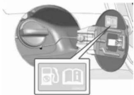
-
Turn the fuel filler cap counterclockwise slowly. If a hissing sound is heard, wait for it to stop before completely unscrewing the cap.
-
Remove the cap. The cap is tethered to the vehicle.
128 Driving and operating
- After refuelling, replace cap. Turn it clockwise until you hear several clicks.
- Push the fuel filler flap closed until it latches.
Notice
If, in cold weather, the fuel filler door does not open, tap the door lightly. Then try to open it again.
Caution
Wipe off any overflowing fuel immediately.
Liquid gas refuelling
Follow the operating and safety instructions of the filling station when refuelling.
The filling valve for the liquid gas is behind the fuel filler cap.

Unscrew protective cap from the filler neck.

Protective cap is magnetic. Place it on fuel filler door while refuelling.

Screw the required adapter hand-tight onto the filler neck.
ACME Adapter: Screw the nut of the filling nozzle onto the adapter. Press locking lever on filler nozzle down.
DISH filler neck: Place the filler nozzle into the adapter. Press locking lever on filler nozzle down.
Bayonet filler neck: Place filler nozzle on the adapter and turn clockwise or anticlockwise through one quarter turn. Pull locking lever of filler nozzle fully.
EURO filler neck: Press the filler nozzle onto the adapter until it engages.
Press the button at the liquid gas supply point. The filling system stops or begins to run slowly when 80% of the tank volume is reached (maximum fill level).
Release button on filling system and the filling process stops. Release the locking lever and remove the filler nozzle. A small quantity of liquid gas may escape.
Remove adapter and stow securely in vehicle.
Fit protective cap to prevent the penetration of foreign bodies into the filler opening and the system.
Warning
Due to the system design, an escape of liquid gas after releasing the locking lever is unavoidable. Avoid inhaling.
⚠ Warning
The liquid gas tank should only be filled to 80% capacity, for safety reasons.
The multivalve on the liquid gas tank automatically limits the fill quantity. If a larger quantity is added, we recommend not exposing the vehicle to the sun until the excess amount has been used up.
Filling adapter
As filling systems are not standardised, different adapters are required which are available from Vauxhall Distributors and from Vauxhall Authorised Repairers.

ACME adapter: Belgium, Germany, Ireland, Luxembourg, Switzerland

Bayonet adapter: Netherlands, Norway, Spain, United Kingdom

EURO adapter: Spain
130 Driving and operating

DISH adapter: Austria, Bosnia-Herzegovina, Bulgaria, Croatia, Czech Republic, Denmark, Estonia, France, Greece, Hungary, Italy, Latvia, Lithuania, Macedonia, Poland, Portugal, Romania, Serbia, Slovakia, Slovenia, Sweden, Switzerland, Turkey, Ukraine
Fuel filler cap
Only use genuine fuel filler caps.
Fuel consumption - CO 2 -Emissions
The fuel consumption (combined) of the model Vauxhall Viva is within a range of 61.4 to 68.9 mpg.
The CO2 emission (combined) is within a range of 106 to 94 g/km.
For the values specific for your vehicle, refer to the EEC Certificate of Conformity provided with your vehicle or other national registration documents.
General information
The official fuel consumption and specific CO2 emission figures quoted relate to the EU base model with standard equipment.
Fuel consumption data and CO2 emission data are determined according to regulation R (EC) No. 715/2007 (in the latest applicable version), taking into consideration the vehicle weight in running order, as specified by the regulation.
The figures are provided only for the purpose of comparison between different vehicle variants and must not be taken as a guarantee for the actual fuel consumption of a particular vehicle. Additional equipment may result in slightly higher results than the stated consumption and CO2 figures.
Furthermore, fuel consumption is dependent on personal driving style as well as road and traffic conditions.
Vehicle care
General Information ...... 131
Accessories and vehicle
modifications 131
Vehicle storage 132
End-of-life vehicle recovery ..... 132
Vehicle checks 133
Performing work 133
Bonnet 133
Engine oil 134
Engine coolant 135
Washer fluid 135
Brakes 136
Brake fluid 136
Vehicle battery 136
Wiper blade replacement ..... 138
Bulb replacement 138
Halogen headlights 139
Fog lights 140
Front turn signal lights 141
Tail lights 141
Side turn signal lights 142
Centre high-mounted brake
light 143
Number plate light 143
Interior lights 144
Instrument panel illumination ... 144
Electrical system 144
Fuses 144
Engine compartment fuse box . 146
Instrument panel fuse box ..... 147
Vehicle tools 149
Tools 149
Wheels and tyres 150
Winter tyres 150
Tyre designations 150
Tyre pressure 150
Tyre pressure monitoring system 151
Tread depth 155
Changing tyre and wheel size . 155
Wheel covers 155
Tyre chains 156
Tyre repair kit 156
Wheel changing 159
Spare wheel 161
Jump starting 163
Towing 165
Towing the vehicle 165
Appearance care 166
Exterior care 166
Interior care 168
General Information
Accessories and vehicle modifications
We recommend the use of genuine parts and accessories and factory approved parts specific for your vehicle type. We cannot assess or guarantee reliability of other products - even if they have a regulatory or otherwise granted approval.
Do not make any modifications to the electrical system, e.g. changes of electronic control units (chip tuning).
Caution
When transporting the vehicle on a train or on a recovery vehicle, the mud flaps might be damaged.
132 Vehicle care
Vehicle storage
Storage for a long period of time
If the vehicle is to be stored for several months:
- Wash and wax the vehicle.
- Have the wax in the engine compartment and underbody checked.
- Clean and preserve the rubber seals.
- Fill up fuel tank completely.
- Change the engine oil.
- Drain the washer fluid reservoir.
- Check the coolant antifreeze and corrosion protection.
- Adjust tyre pressure to the value specified for full load.
- Park the vehicle in a dry, well ventilated place. Engage first or reverse gear. Prevent the vehicle from rolling.
-
Do not apply the parking brake.
-
Open the bonnet, close all doors and lock the vehicle.
- Disconnect the clamp from the negative terminal of the vehicle battery. Beware that all systems are not functional, e.g. anti-theft alarm system.
Putting back into operation
When the vehicle is to be put back into operation:
- Connect the clamp to the negative terminal of the vehicle battery. Activate the electronics of the power windows.
- Check tyre pressure.
- Fill up the washer fluid reservoir.
- Check the engine oil level.
- Check the coolant level.
- Fit the number plate if necessary.
End-of-life vehicle recovery
Information on end-of-life vehicle recovery centres and the recycling of end-of-life vehicles is available on our website. Only entrust this work to an authorised recycling centre.
Gas vehicles must be recycled by a service centre authorised for gas vehicles.
Vehicle checks
Performing work
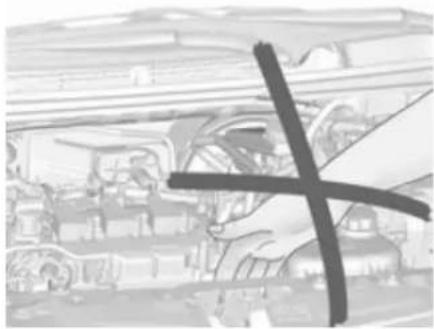
Warning
Only perform engine compartment checks when the ignition is off.
The cooling fan may start operating even if the ignition is off.
⚠️ Danger
The ignition system uses extremely high voltage. Do not touch.
Bonnet
Opening
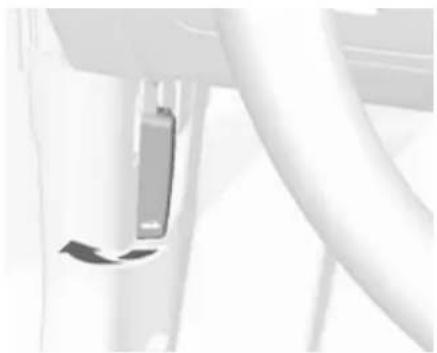
Pull the release lever and return it to its original position.
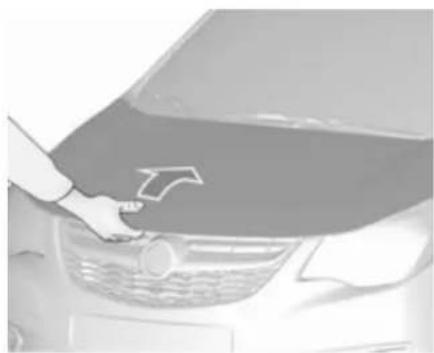
Push the safety catch upwards and open the bonnet.

Secure the bonnet support.
134 Vehicle care
If the bonnet is opened during an Autostop, the engine will be restarted automatically for safety reasons.
Closing
Before closing the bonnet, press the support into the holder.
Lower the bonnet and allow it to fall into the latch from a low height (20-25 cm). Check that the bonnet is engaged.
Caution
Do not press the bonnet into the latch, to avoid dents.
Engine oil
Check the engine oil level manually on a regular basis to prevent damage to the engine.
Ensure that the correct specification of oil is used. Recommended fluids and lubricants ⇒ 170.
The maximum engine oil consumption is 0.6 l per 1000 km.
Check with the vehicle on a level surface. The engine must be at operating temperature and switched off for at least five minutes.
Pull out the dipstick, wipe it clean, insert it to the stop on the handle, pull out and read the engine oil level.
Caution
It is the owner's responsibility to maintain the proper level of an appropriate quality oil in the engine.
Insert dipstick to the stop on the handle and make half a turn.
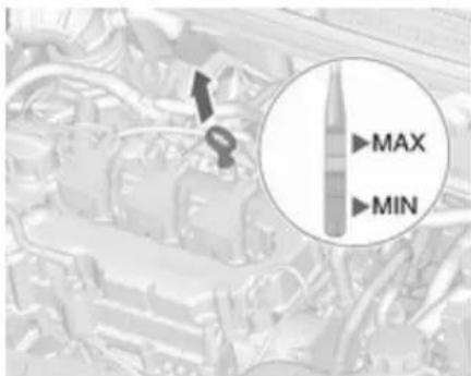
When the engine oil level has dropped to the MIN mark, top up engine oil.

We recommend the use of the same grade of engine oil that was used at last change.
The engine oil level must not exceed the MAX mark on the dipstick.
Caution
Overfilled engine oil must be drained or suctioned out.
Capacities ↩ 181.
Fit the cap on straight and tighten it.
Engine coolant
The coolant provides freeze protection down to approx. -28 °C. In northern countries with very low temperatures the factory filled coolant provides frost protection down to approx. -37 °C.
Caution
Only use approved antifreeze.
Coolant level
Caution
Too low a coolant level can cause engine damage.
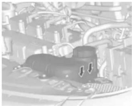
If the cooling system is cold, the coolant level should be above the filling line mark. Top up if the level is low.
Warning
Allow the engine to cool before opening the cap. Carefully open the cap, relieving the pressure slowly.
To top up use a 1:1 mixture of released coolant concentrate mixed with clean tap water. If no coolant concentrate is available, use clean tap water. Install the cap tightly. Have
the coolant concentration checked and have the cause of the coolant loss remedied by a workshop.
Washer fluid
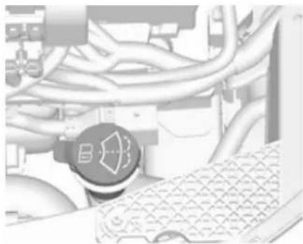
Fill with clean water mixed with a suitable quantity of approved windscreen washer fluid which contains antifreeze.
Caution
Only washer fluid with a sufficient antifreeze concentration provides protection at low temperatures or a sudden drop in temperature.
136 Vehicle care
Brakes
In the event of minimum thickness of the brake lining, a squealing noise sounds during braking.
Continued driving is possible but have the brake lining replaced as soon as possible.
Once new brake linings are installed, do not brake unnecessarily hard for the first few journeys.
Brake fluid

Warning
Brake fluid is poisonous and corrosive. Avoid contact with eyes, skin, fabrics and painted surfaces.
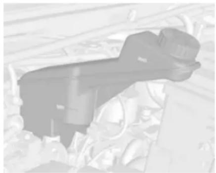
The brake fluid level must be between the MIN and MAX marks.
If fluid level is below MIN seek the assistance of a workshop.
Brake and clutch fluid ↩ 170.
Vehicle battery
The vehicle battery is maintenance-free provided that the driving profile allows sufficient charging of the battery. Short-distance-driving and frequent engine starts can discharge the vehicle battery. Avoid the use of unnecessary electrical consumers.

Batteries do not belong in household waste. They must be disposed of at an appropriate recycling collection point.
Laying up the vehicle for more than four weeks can lead to vehicle battery discharge. Disconnect the clamp from the negative terminal of the vehicle battery.
Ensure the ignition is switched off before connecting or disconnecting the vehicle battery.
The anti-theft alarm siren must be deactivated as follows: Switch the ignition on then off, disconnect the vehicle's battery within 15 seconds.
Battery discharge protection ↗ 93.
Replacing the vehicle battery
Notice
Any deviation from the instructions given in this section may lead to temporary deactivation of the stop-start system.
When the vehicle battery is being replaced, please ensure that there are no open ventilation holes in the vicinity of the positive terminal. If a ventilation hole is open in this area, it must be closed off with a dummy cap, and the ventilation in the vicinity of the negative terminal must be opened.
In vehicles with an AGM (Absorptive Glass Mat) battery, make sure to have the battery replaced with another AGM battery.
We recommend the use of an original Vauxhall battery.
Notice
Using an AGM vehicle battery different from the original Vauxhall vehicle battery may result in a lower performance.
We recommend that you have the vehicle battery replaced by a workshop.
Stop-start system ↩ 106.
Charging the vehicle battery
Warning
On vehicles with stop-start system, ensure that the charging potential does not exceed 14.6 volts when using a battery charger. Otherwise the battery might be damaged.
Jump starting 163.
Warning label

Meaning of symbols:
- No sparks, naked flames or smoking.
• Always shield eyes. Explosive gases can cause blindness or injury. - Keep the vehicle battery out of the reach of children.
- The vehicle battery contains sulfuric acid which could cause blindness or serious burn injuries.
138 Vehicle care
• See the Owner's manual for further information.
- Explosive gas may be present in the vicinity of the battery.
Wiper blade replacement

Lift the wiper arm. Press release lever and detach the wiper blade.
Attach the wiper blade slightly angled to the wiper arm and push until it engages.
Lower wiper arm carefully.
Wiper blade on the rear window

Lift wiper arm. Push the wiper blade, slightly angled to the wiper arm downwards until it disengages.
Attach the wiper blade slightly angled to the wiper arm and push until it engages.
Lower wiper arm carefully.
Bulb replacement
Switch off the ignition and switch off the relevant switch or close the doors.
Only hold a new bulb at the base! Do not touch the bulb glass with bare hands.
Use only the same bulb type for replacement.
Replace headlight bulbs from within the engine compartment.
Bulb check
After a bulb replacement switch on the ignition, operate and check the lights.
Halogen headlights
Low beam and high beam
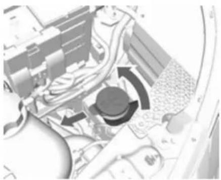
- On left vehicle side: rotate and pull out the filling pipe of the windscreen washer fluid container.

- Remove fuse box cover (left side of the vehicle only).

- Press both clips together and detach plug connector from bulb.
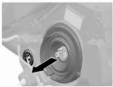
- Remove protective cover.

- Press spring clip and disengage.
140 Vehicle care

- Remove bulb from reflector housing.
- When fitting a new bulb, engage the lugs in the recesses on the reflector.
- Engage the spring clip.
- Place headlight protective cover in position and close.
- Ensure the protective cover is placed correctly to prevent water leak and heavy condensations.
Sidelight/Daytime running light
- Remove fuse box cover (left side of the vehicle only).

- Rotate the bulb holder anticlockwise and remove.
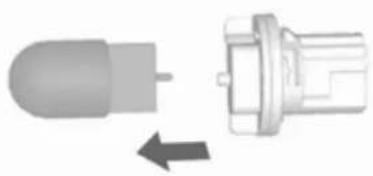
- Detach bulb from the bulb holder and replace it.
- Insert the bulb socket into the reflector and turn clockwise.
Sidelight/daytime running light with LEDs
Sidelights and daytime running lights are designed as LEDs and cannot be changed. Consult a workshop in case of a defective LED.
Fog lights
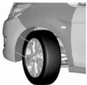
- Tilt the wheel and remove the two push nuts on the outside of the wheel liner.

- Disconnect the electrical connector from the bulb holder.
- Remove the bulb assembly anticlockwise and pull it straight out.
- Insert a new bulb assembly straight into the lamp and rotate clockwise.
- Reconnect the electrical connector.
Front turn signal lights
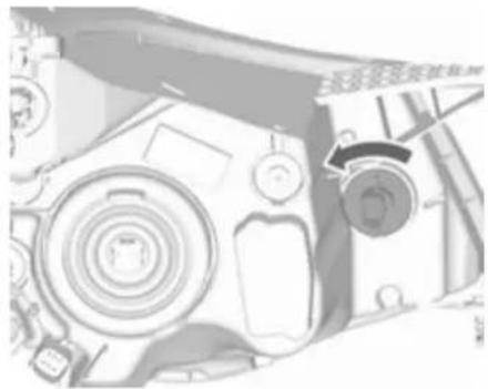
- Rotate the bulb holder anticlockwise and remove.

- Rotate bulb anticlockwise and remove from bulb holder.
- Replace bulb.
- Insert the bulb holder into the reflector and rotate clockwise.
Tail lights
Tail lights, turn signal lights, brake lights and reversing lights

- Unscrew both screws.
- Remove tail light assembly. Take care that the cable duct remains in position.
142 Vehicle care

- tail light / brake light 1 turn signal light 2 tail light 3 reversing light (passenger side) / rear fog light (driver's side) 4.

- Rotate bulb holder anticlockwise.

-
Remove bulb holder. Push bulb into socket slightly, rotate anti-clockwise, remove and renew bulb.
-
Insert bulb holder into the tail light assembly and screw into place. Connect wiring plug. Install tail light assembly in body and tighten screws. Close covers and engage.
- Switch on ignition, operate and check all lights.
Side turn signal lights
To replace bulb, remove lamp housing:
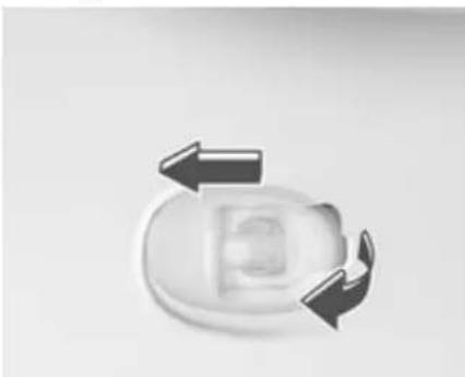
- Slide lamp to the front and remove it out of the front wing with the rear end.

- Turn bulb holder anticlockwise and remove from housing.

-
Pull bulb from bulb holder and replace it.
-
Insert bulb holder and turn clockwise.
- Insert front end into front wing, slide forward and insert rear end.
Centre high-mounted brake light

Have LEDs replaced by a workshop.
Number plate light

- Unscrew both screws.
- Remove bulb housing downwards, taking care not to pull on the cable.
Rotate bulb holder anticlockwise to disengage. - Remove bulb from bulb holder and replace it.
- Insert bulb holder into bulb housing and turn clockwise.
- Insert bulb housing and secure using a screwdriver.
144 Vehicle care
Interior lights
Courtesy light, reading lights
- To remove, prise the opposite side of the lamp switch using a flat-blade screwdriver. (Be careful not to make scratches.)
- Remove the bulb.
- Replace the bulb.
- Reinstall the lamp assembly.
Load compartment light

- Prise the lamp out with a screwdriver.

- Remove bulb.
- Insert new bulb.
- Install lamp.
Instrument panel illumination
Have bulbs replaced by a workshop.
Electrical system
Fuses
Data on the replacement fuse must match the data on the defective fuse.
There are two fuse boxes in the vehicle:
- In the front left of the engine compartment.
- On the driver's side behind a cover in the instrument panel.
Before replacing a fuse, turn off the respective switch and the ignition.
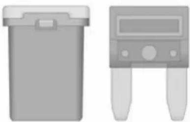
There are different kinds of fuses in the vehicle. Some types of fuses in the vehicle may differ from the ones illustrated.
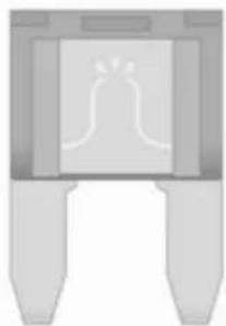
Depending on the type of fuse, a blown fuse can be recognized by its melted wire. Do not replace the fuse until the cause of the fault has been remedied.
Some functions are protected by several fuses.
Fuses may also be inserted without existence of a function.
Fuse extractor
A fuse extractor may be located in the fuse box in the engine compartment.

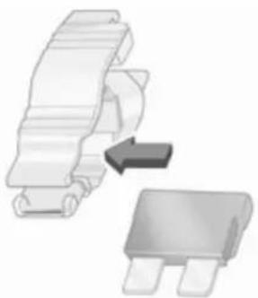

Place the fuse extractor on the various types of fuse from the top, and withdraw fuse.
146 Vehicle care
Engine compartment fuse box
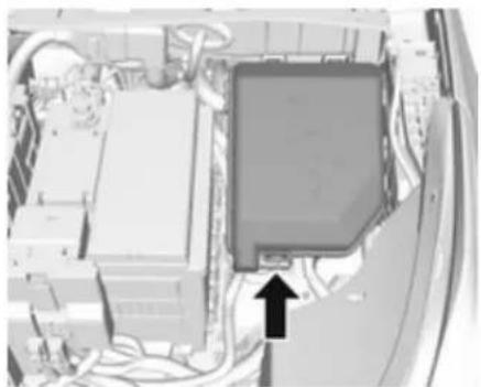
The fuse box is in the front left of the engine compartment.
Disengage the cover, lift it upwards and remove.

No. Circuit
1 Tailgate
2-
3 Heated rear window
4 Heated exterior mirror
5 Sunroof
6 Transmission control module
7 Engine control module
8 -
9 ABS
10 Body control module, voltage
11 Rear view camera
12-
13-
14 Engine control module/Transmission control module
15 Injection system/Starter
16 Fuel pump
17 Engine control module1
No. Circuit
18 Engine control module2
19 Injection system/Ignition
20 Air conditioning system
21 Battery sensor
22 Electric steering column lock
23 Cooling fan low
24 -
25 Exterior mirror switch
26 Engine control module/Manual transmission automated module
27 Fuel system
28 Brake switch
29 Seat occupancy recognition
30 Headlight range adjustment
31 Horn
32 Front fog light
33 High beam left
No. Circuit
34 High beam right
35 -
36 Rear wiper
37 Cornering light left
38 Washer system
39 Cornering light right
40 -
41 -
42 Starter 2
43 Instrument panel
44 Manual transmission auto- mated
45 Starter 1
46 ABS
47 Cooling fan high
48 Front wiper
49 Body control module/Retained power off
After having changed defective fuses close the fuse box cover and press until it engages.
If the fuse box cover is not closed correctly, malfunction may occur.
Instrument panel fuse box

The fuse box is located on the driver's side behind a cover in the instrument panel.
To open the compartment, compress the locking tabs, fold cover down and remove.

No. Circuit
1 Onstar
2 Air conditioning system
3 Instrument panel
4 Transmission control module
5 Infotainment
6 Body control module
7 Rear parking assist
8 Data link connection
9 Electric steering column lock
10 Sensing and Diagnostic module
11 DC transformer
12 -
13 Electronic toll collection system
14 Linear power module
15 Central locking system/Ignition system
16 Ignition system
No. Circuit
17 forward collision alert
18 Instrument panel
19 Forward collision alert indication
20 Headlight range adjustment
21 Power windows, front
22 Power windows, rear
23-
24 Manual transmission auto-
mated module
25 Auxiliary power outlet
26 Sunroof
27-
28 Body control module 8
29 Body control module 7
30 Body control module 6
31 Body control module 5
32 Body control module 4
No. Circuit
33 Body control module 3
34 Body control module 2
35 Body control module 1
36 Ignition system
37 Steering wheel control LED
38-
39 Logistic/DC transformer
40 Power window, driver
41 Blower
42 Seat heating, front
43 Air conditioning module
44 Heated steering wheel
45 Body control module 2
Vehicle tools
Tools
Vehicles with tyre repair kit

The vehicle tools are in the compartment under the floor cover in the load compartment, together with the tyre repair kit.
Vehicles with spare wheel

The jack and the vehicle tools are in the load compartment.
150 Vehicle care
Wheels and tyres
Tyre condition, wheel condition
Drive over edges slowly and at right angles if possible. Driving over sharp edges can cause tyre and wheel damage. Do not trap tyres on the kerb when parking.
Regularly check the wheels for damage. Seek the assistance of a workshop in the event of damage or unusual wear.
We recommend not swapping the front wheels with the rear wheels and vice versa, as this can affect vehicle stability. Always use less worn tyres on the rear axle.
Winter tyres
Winter tyres improve driving safety at temperatures below 7 °C and should therefore be fitted on all wheels.
In accordance with country-specific regulations, affix the speed sticker in the driver's field of view.
Tyre designations
E.g. 195/55 R 16 95 H
195 : tyre width, mm
55 : cross-section ratio (tyre height to tyre width), %
R : belt type: Radial
RF : type: RunFlat
16 : wheel diameter, inches
91 : load index e.g. 91 is equivalent to 615 kg
H : speed code letter
Speed code letter:
Q: up to 100 mph
S : up to 112 mph
T: up to 118 mph
H: up to 130 mph
V: up to 150 mph
W : up to 168 mph
Choose a tyre appropriate for the maximum speed of your vehicle.
The maximum speed is achievable at kerb weight with driver (75 kg) plus 125 kg payload. Optional equipment could reduce the maximum speed of the vehicle.
Performance 178.
Directional tyres
Directional tyres must be mounted so that they rotate in the correct direction. The proper rotation direction is indicated by a symbol (e.g. an arrow) on the sidewall.
Tyre pressure
Check the pressure of cold tyres at least every 14 days and before any long journey.
Do not forget the spare wheel.
This also applies to vehicles with tyre pressure monitoring system.
Unscrew the valve cap.

Tyre pressure ➔ 182.
The tyre pressure information label on the driver's door frame indicates the original equipment tyres and the correspondent tyre pressures.
The tyre pressure data refers to cold tyres. It applies to summer and winter tyres.
The ECO tyre pressure serves to achieve the smallest amount of fuel consumption possible.
Incorrect tyre pressures will impair safety, vehicle handling, comfort and fuel economy and will increase tyre wear.
Tyre pressures differ depending on various options.
For the correct tyre pressure value, follow the procedure below:
- Identify the engine identifier code. Engine data ⇒ 177.
- Identify the respective tyre.
For the tyres approved for your vehicle, refer to the EEC Certificate of Conformity provided with your vehicle or other national registration documents.
The driver is responsible for correct adjustment of tyre pressure.
⚠ Warning
If the pressure is too low, this can result in considerable tyre warm-up and internal damage, leading to tread separation and even to tyre blow-out at high speeds.
Warning
For specific tyres the recommended tyre pressure as shown in the tyre pressure table may exceed the maximum tyre pressure as indicated on the tyre. Never exceed the maximum tyre pressure as indicated on the tyre.
If the tyre pressure must be reduced or increased, switch off ignition. After adjusting tyre pressure switch on ignition and select the relevant setting on the page Tyre Load in the Driver Information Centre 73.
Temperature dependency
The tyre pressure depends on the temperature of the tyre. During driving, tyre temperature and pressure increase. Tyre pressure values provided on the tyre information label and tyre pressure chart are valid for cold tyres, which means at 20 °C.
The pressure increases by nearly 1.5 psi for a 10 °C temperature increase. This must be considered when warm tyres are checked.
The tyre pressure value displayed in the Driver Information Centre shows the real tyre pressure. A cooled down tyre will show a decreased value, which does not indicate an air leak.
Tyre pressure monitoring system
The tyre pressure monitoring system checks the pressure of all four tyres once a minute when vehicle speed exceeds a certain limit.
152 Vehicle care
Caution
Tyre pressure monitoring system warns only about low tyre pressure condition and does not replace regular tyre maintenance by the driver.
All wheels must be equipped with pressure sensors and the tyres must have the prescribed pressure.
Notice
In countries where the tyre pressure monitoring system is legally required, the use of wheels without pressure sensors will invalidate the vehicle type approval.
The current tyre pressures can be shown in the Vehicle Information Menu in the Driver Information Centre.
The menu can be selected by pressing the buttons on the turn signal lever.

Press MENU to select the Vehicle Information Menu.

Turn the adjuster wheel to select the tyre pressure monitoring system.
System status and pressure warnings are displayed by a message with the corresponding tyre flashing in the Driver Information Centre.
The system considers the tyre temperature for the warnings.
Temperature dependency 150.

A detected low tyre pressure condition is indicated by the control indicator ⏻ 71.
If ⏻ illuminates, stop as soon as possible and inflate the tyres as recommended ➔ 182.
If (!) flashes for 60-90 seconds then illuminates continuously, there is a fault in the system. Consult a workshop.
After inflating, some driving may be required to update the tyre pressure values in the Driver Information Centre. During this time (↓) may illuminate.
If (☐) illuminates at lower temperatures and extinguishes after some driving, this could be an indicator for approaching a low tyre pressure condition. Check tyre pressure.
Vehicle messages ↩ 79.
If the tyre pressure must be reduced or increased, switch off ignition.
Only mount wheels with pressure sensors, otherwise the tyre pressure will not be displayed and ⏻ illuminates continuously.
A temporary spare wheel is not equipped with pressure sensors. The tyre pressure monitoring system is not operational for these tyres.
Control indicator (!) illuminates. For the further three tyres, the system remains operational.
The use of commercially-available liquid tyre repair kits can impair the function of the system. Factory-approved repair kits can be used.
Operating electronic devices or being close to facilities using similar wave frequencies could disrupt the tyre pressure monitoring system.
Each time the tyres are replaced, tyre pressure monitoring system sensors must be dismounted and serviced. For the screwed sensor; replace valve core and sealing ring. For the clipped sensor; replace complete valve stem.
Vehicle loading status
Adjust tyre pressure to load condition according to the tyre information label or tyre pressure chart 182, and select the appropriate setting in the menu Tyre Load in the Driver Information Centre, Vehicle Information Menu 73. This setting is the reference for the tyre pressure warnings.
The Tyre Load menu only appears if the vehicle is in a standstill and the parking brake is applied. On vehicles with automatic transmission the selector lever has to be in P.

Select:
- Lo for comfort pressure up to 3 people.
- Eco for Eco pressure up to 3 people.
- Hi for full loading.
154 Vehicle care
Tyre pressure sensor matching process
Each tyre pressure sensor has a unique identification code. The identification code must be matched to a new tyre/wheel position after rotating the tyres or exchanging the complete wheel set and if one or more tyre pressure sensors were replaced. The tyre pressure sensor matching process should also be performed after replacing a spare tyre with a road tyre containing the tyre pressure sensor.
The malfunction light ( ) and the warning message or code should go off at the next ignition cycle. The sensors are matched to the wheel positions, using a relearn tool, in the following order: left side front wheel, right side front wheel, right side rear wheel and left side rear wheel. The turn signal light at the current active position is illuminated until sensor is matched.
Consult a workshop for service or purchase a relearn tool. There are two minutes to match the first wheel position, and five minutes overall to match all four wheel positions. If it takes longer, the matching process stops and must be restarted.
The tyre pressure sensor matching process is:
- Apply the parking brake.
- Turn the ignition on.
- On vehicles with manual transmission automated: Press and hold brake pedal. Move and hold the selector lever for five seconds in position N until P is displayed in the Driver Information Centre. P indicates that the sensor matching process can be started.
On vehicles with manual transmission: select neutral.
-
Use MENU on the turn signal lever to select the Vehicle Information Menu in the Driver Information Centre.
-
Turn the adjuster wheel to scroll to the tyre pressure menu.
-
Press SET/CLR to begin the sensor matching process. A message requesting acceptance of the process should be displayed.
-
Press SET/CLR again to confirm the selection. The horn sounds twice to indicate that the receiver is in relearn mode.
-
Start with the left side front wheel.
-
Place the relearn tool against the tyre sidewall, near the valve stem. Then press the button to activate the tyre pressure sensor. A horn chirp confirms that the sensor identification code has been matched to this wheel position.
-
Proceed to the right side front wheel, and repeat the procedure in Step 9.
-
Proceed to the right side rear wheel, and repeat the procedure in Step 9.
-
Proceed to the left side rear wheel, and repeat the procedure in Step 9. The horn sounds twice to indicate that the sensor identification code has been
matched to the left side rear wheel, and the tyre pressure sensor matching process is no longer active.
- Turn off the ignition.
- Set all four tyres to the recommended air pressure level as indicated on the tyre information label.
- Ensure the tyre loading status is set according to the selected pressure ⇒ 73.
Tread depth
Check tread depth at regular intervals.
Tyres should be replaced for safety reasons at a tread depth of 2-3 mm (4 mm for winter tyres).
For safety reasons it is recommended that the tread depth of the tyres on one axle should not vary by more than 2 mm.

The legally permissible minimum tread depth (1.6 mm) has been reached when the tread has worn down as far as one of the tread wear indicators (TWI). Their position is indicated by markings on the sidewall.
Tyres age, even if they are not used. We recommend tyre replacement every 6 years.
Changing tyre and wheel size
If tyres of a different size than those fitted at the factory are used, it may be necessary to reprogramme the
speedometer as well as the nominal tyre pressure and to make other vehicle modifications.
After converting to a different tyre size, have the label with tyre pressures replaced.
⚠ Warning
Use of unsuitable tyres or wheels may lead to accidents and will invalidate the vehicle type approval.
Wheel covers
Wheel covers and tyres that are factory approved for the respective vehicle and comply with all of the relevant wheel and tyre combination requirements must be used.
If the wheel covers and tyres used are not factory approved, the tyres must not have a rim protection ridge.
Wheel covers must not impair brake cooling.
156 Vehicle care

Warning
Use of unsuitable tyres or wheel covers could lead to sudden pressure loss and thereby accidents.
Tyre chains

Tyre chains are only permitted on the front wheels.
Always use fine mesh chains that add no more than 10 mm to the tyre tread and the inboard sides (including chain lock).
⚠ Warning
Damage may lead to tyre blowout.
Tyre chains are only permitted on tyres of size 165/65 R14.
Tyre chains are not permitted on tyres of size 185/55 R15 and 195/45 R16.
The use of tyre chains is not permitted on the temporary spare wheel.
Tyre repair kit
Minor damage to the tyre tread can be repaired with the tyre repair kit.
Do not remove foreign bodies from the tyres.
Tyre damage exceeding 4 mm or that is at the tyre's sidewall cannot be repaired with the tyre repair kit.
Warning
Do not drive faster than 50 mph.
Do not use for a lengthy period.
Steering and handling may be affected.
If you have a flat tyre:
Apply the parking brake and engage first gear or reverse gear.

The tyre repair kit is in the tool box under the floor cover in the load compartment.
- Open the floor cover.

- Remove the compressor and the sealant bottle.

- Remove the electrical connection cable and air hose from the storage compartments on the underside of the compressor.

-
Screw the compressor air hose to the connection on the sealant bottle.
-
Fit the sealant bottle into the retainer on the compressor. Set the compressor near the tyre in such a way that the sealant bottle is upright.

- Unscrew valve cap from defective tyre.
- Screw the filler hose to the tyre valve.
- The switch on the compressor must be set to O.
- Connect the compressor plug to the power outlet or cigarette lighter socket.
To avoid discharging the battery, we recommend running the engine.
158 Vehicle care
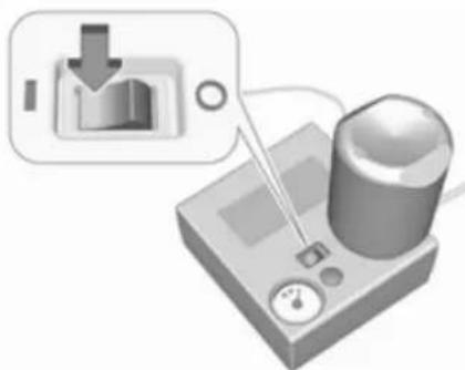
Set the rocker switch on the compressor to I. The tyre is filled with sealant.
-
The compressor pressure gauge briefly indicates up to six bar whilst the sealant bottle is emptying (approx. 30 seconds). Then the pressure starts to drop.
-
All of the sealant is pumped into the tyre. Then the tyre is inflated.
-
The prescribed tyre pressure should be obtained within ten minutes. Tyre pressure 182. When the correct pressure is obtained, switch off the compressor.
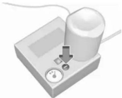
If the prescribed tyre pressure is not obtained within ten minutes, remove the tyre repair kit. Move the vehicle one tyre rotation.
Reattach the tyre repair kit and continue the filling procedure for ten minutes. If the prescribed tyre pressure is still not obtained, the tyre is too badly damaged. Seek the assistance of a workshop.
Drain excess tyre pressure with the button over the pressure indicator.
Do not run the compressor for longer than ten minutes.
-
Detach the tyre repair kit. Push catch on bracket to remove sealant bottle from bracket. Screw the tyre inflation hose to the free connection of the sealant bottle. This prevents sealant from escaping. Stow tyre repair kit in load compartment.
-
Remove any excess sealant using a cloth.
-
Take the label indicating maximum permitted speed from the sealant bottle and affix in the driver's field of view.
-
Continue driving immediately so that sealant is evenly distributed in the tyre. After driving approx. six miles (but no more than ten minutes), stop and check tyre pressure. Screw compressor air hose directly onto tyre valve and compressor when doing this.
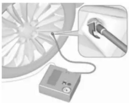
If tyre pressure is more than
1.3 bar, set it to the correct value.
Repeat the procedure until there is no more loss of pressure.
If the tyre pressure has fallen below 1.3 bar, the vehicle must not be used. Seek the assistance of a workshop.
- Stow away tyre repair kit in load compartment.
Reinstall floor cover. Rear floor storage cover ⇒ 53.
Notice
The driving characteristics of the repaired tyre are severely affected, therefore have this tyre replaced.
If unusual noise is heard or the compressor becomes hot, turn compressor off for at least 30 minutes.
The built-in safety valve opens at a pressure of seven bar (102 psi).
Note the expiry date of the kit. After this date its sealing capability is no longer guaranteed. Pay attention to storage information on sealant bottle.
Replace the used sealant bottle. Dispose of the bottle as prescribed by applicable laws.
The compressor and sealant can be used from approx. -30 °C.
The adapters supplied can be used to pump up other items e.g. footballs, air mattresses, inflatable dinghies etc. They are located on the underside of the compressor. To remove, screw on compressor air hose and withdraw adapter.
Wheel changing
Some vehicles are equipped with a tyre repair kit instead of a spare wheel.
Make the following preparations and observe the following information:
- Park the vehicle on a level, firm and non-skid surface. The front wheels must be in the straight-ahead position.
- Apply the parking brake and engage first gear or reverse gear.
- Never change more than one wheel at once.
- Use the jack only to change wheels in case of puncture, not for seasonal winter or summer tyre change.
- The jack is maintenance-free.
- If the ground on which the vehicle is standing is soft, a solid board (max. 1 cm thick) should be placed under the jack.
• Take heavy objects out of the vehicle before jacking up. - No people or animals may be in the vehicle when it is jacked-up.
- Never crawl under a jacked-up vehicle.
160 Vehicle care
- Do not start the vehicle when it is raised on the jack.
- Clean wheel nuts and thread with a clean cloth before mounting the wheel.
Warning
Do not grease wheel bolt, wheel nut and wheel nut cone.
1. Steel wheels:
Pull off the wheel cover.
Alloy wheels with bolt caps
Disengage wheel bolt caps with a screwdriver and remove. To protect the wheel, place a soft cloth between the screwdriver and the alloy wheel.
Alloy wheels with centre cap
Insert extractor in the open slot of the centre cap and remove the cap from the wheel. Vehicle tools 149.

- Install the wheel wrench ensuring that it locates securely and loosen each wheel bolt by half a turn.
The wheels might be protected by locking wheel bolts. To loosen these specific bolts, first attach the adapter for the locking wheel bolts onto the head of the bolt before installing the wheel wrench. The adapter is located in the glovebox.

- Ensure the jack is correctly positioned under the relevant vehicle jacking point.
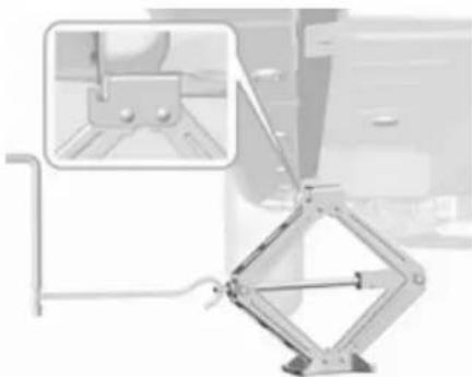
- Set the jack to the necessary height. Position it directly below
the jacking point in a manner that prevents it from slipping.
Attach jack handle and with the jack correctly aligned rotate handle until wheel is clear of the ground.
-
Unscrew the wheel bolts.
-
Change the wheel.
-
Screw on the wheel bolts.
-
Lower vehicle.
-
Install the wheel wrench ensuring that it locates securely and tighten each bolt in a crosswise sequence. Tightening torque is 140 Nm.
-
Align the valve hole in the wheel cover of the steel wheel with the tyre valve before installing. Install wheel bolt caps or centre cap on alloy wheel.
-
Stow and secure the replaced wheel, the vehicle tools ⇔ 149 and the adapter for the locking wheel bolts ⇔ 49.
-
Check the tyre pressure of the installed tyre and the wheel bolt torque as soon as possible.
Have the defective tyre renewed or repaired as soon as possible.
Jacking position for lifting platform
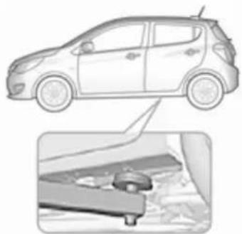
Rear arm position of the lifting platform, located centrally under the recess of the sill.
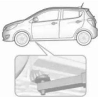
Front arm position of the lifting platform at the underbody.
Spare wheel
Some vehicles are equipped with a tyre repair kit instead of a spare wheel.
If mounting a spare wheel, which is different from the other wheels, this wheel might be classified as a temporary spare wheel and the corresponding speed limits apply, even though no label indicates this. Seek the assistance of a workshop to check the applicable speed limit.
The spare wheel has a steel rim.
162 Vehicle care
Caution
The use of a spare wheel that is smaller than the other wheels or in combination with winter tyres could affect driveability. Have the defective tyre replaced as soon as possible.

The spare wheel is located in the load compartment beneath the floor covering. It is secured in the recess with a wing bolt.
The spare wheel well is not designed for all permitted tyre sizes. If a wheel wider than the spare must be stowed
in the spare wheel well after changing wheels, the floor cover can be placed on the projecting wheel.
Temporary spare wheel
Caution
The use of the temporary spare wheel could affect driveability. Have the defective tyre renewed or repaired as soon as possible.
Only mount one temporary spare wheel. Do not drive faster than 50 mph. Take curves slowly. Do not use for a long period of time.
If your vehicle gets a flat tyre on the rear while towing another vehicle, mount the temporary spare wheel in the front and the full size tyre in the rear.
Tyre chains ↩ 156.
Storing a damaged wheel in the load compartment using a strap
Use the strap placed in the tool box. Vehicle tools ➔ 149.
-
Remove load compartment cover and lift up load compartment floor. Position the tool box and the damaged wheel to stand upright into the tool box spare.
-
Pull up the release knob on top of the rear seat and move backrest forwards.

-
Place the loop end of the strap from the tool box through the backrest latch.
-
Place the hook end of the strap through the loop and pull it until the strap is fastened securely to the backrest latch.
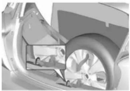
- Pull back the backrests.
- Mount the hook to the tailgate latch.
- Tighten the strap and secure it using the buckle.
Warning
Storing a jack, a wheel or other equipment in the load compartment could cause injury if they are not fixed properly. During a sudden stop or a collision, loose equipment could strike someone.
Store jack and tools always in the respective storage compartments and secure them by fixing.
Damaged wheel placed in the load compartment must always be secured by the strap.
Jump starting
Do not start with a quick charger. A vehicle with a discharged vehicle battery can be started using jump leads and the vehicle battery of another vehicle.
Warning
Be extremely careful when starting with jump leads. Any deviation from the following instructions can lead to injuries or damage caused by battery explosion or damage to the electrical systems of both vehicles.
⚠ Warning
Avoid contact of the battery with eyes, skin, fabrics and painted surfaces. The fluid contains sulphuric acid which can cause injuries and damage in the event of direct contact.
- Never expose the battery to naked flames or sparks.
164 Vehicle care
- A discharged vehicle battery can already freeze at a temperature of 0 °C. Defrost the frozen battery before connecting jump leads.
- Wear eye protection and protective clothing when handling a battery.
- Use a booster battery with the same voltage (12 Volts). Its capacity (Ah) must not be much less than that of the discharged battery.
- Use jump leads with insulated terminals and a cross section of at least 16 mm2 .
- Do not disconnect the discharged vehicle battery from the vehicle.
- Switch off all unnecessary electrical consumers.
- Do not lean over the battery during jump starting.
- Do not allow the terminals of one lead to touch those of the other lead.
-
The vehicles must not come into contact with each other during the jump starting process.
-
Apply the parking brake, transmission in neutral.
- Open the positive terminal protection caps of both vehicle batteries.

Lead connection order:
- Connect the red lead to the positive terminal of the booster battery.
-
Connect the other end of the red lead to the positive terminal of the discharged battery.
-
Connect the black lead to the negative terminal of the booster battery.
- Connect the other end of the black lead to a vehicle grounding point, such as the engine block or an engine mounting bolt. Connect as far away from the discharged vehicle battery as possible, however at least 60 cm.
Route the leads so that they cannot catch on rotating parts in the engine compartment.
To start the engine:
- Start the engine of the vehicle providing the jump.
- After five minutes, start the other engine. Start attempts should be made for no longer than 15 seconds at an interval of one minute.
-
Allow both engines to idle for approx. three minutes with the leads connected.
-
Switch on electrical consumers (e.g. headlights, heated rear window) of the vehicle receiving the jump start.
- Reverse above sequence exactly when removing leads.
Towing
Towing the vehicle
The towing eye is stowed with the vehicle tools 149.

- Disengage cap by using the screwdriver and remove the cap.

- Screw in the towing eye as far as it will go until it stops in a horizontal position.
- Attach a tow rope – or better still a tow rod – to the towing eye.
General
The towing eye must only be used for towing and not for recovering the vehicle.
Switch on ignition to release steering wheel lock and to permit operation of brake lights, horn and windscreen wiper.
Transmission in neutral.
Caution
Drive slowly. Do not drive jerkily. Excessive tractive force can damage the vehicle.
When the engine is not running, considerably more force is needed to brake and steer.
To prevent the entry of exhaust gases from the towing vehicle, switch on the air recirculation and close the windows.
The vehicle must be towed facing forward, not faster than 88 km/h. In all other cases and when the transmission is defective, the front axle must be raised off the ground.
Seek the assistance of a workshop.
After towing, unscrew the towing eye.
Insert cap and engage in the front bumper.
Appearance care
Exterior care
Locks
The locks are lubricated at the factory using a high quality lock cylinder grease. Use a de-icing agent only when absolutely necessary, as this has a degreasing effect and impairs lock function. After using a de-icing agent, have the locks regreased by a workshop.
Washing
The paintwork of your vehicle is exposed to environmental influences. Wash and wax your vehicle regularly. When using automatic vehicle washes, select a programme that includes waxing.
Bird droppings, dead insects, resin, pollen and the like should be cleaned off immediately, as they contain aggressive constituents which can cause paint damage.
If using a car wash, comply with the car wash manufacturer's instructions.
The windscreen wiper and rear window wiper must be switched off.
Remove antenna and external accessories such as roof racks etc.
If you wash your vehicle by hand, make sure that the insides of the wheel housings are also thoroughly rinsed out.
Clean edges and folds on opened doors and the bonnet as well as the areas they cover.
Clean bright metal mouldings with a cleaning solution approved for aluminium to avoid damages.
Caution
Always use a cleaning agent with a pH value of four to nine.
Do not use cleaning agents on hot surfaces.
Have the door hinges of all doors greased by a workshop.
Do not clean the engine compartment with a steam-jet or high-pressure jet cleaner.
Thoroughly rinse and leather-off the vehicle. Rinse leather frequently. Use separate leathers for painted and glass surfaces: remnants of wax on the windows will impair vision.
Exterior lights
Headlight and other light covers are made of plastic. Do not use any abrasive or caustic agents, do not use an ice scraper, and do not clean them dry.
Polishing and waxing
Wax painted parts of the vehicle regularly (at the latest when water no longer beads). Otherwise, the paintwork will dry out.
Polishing is necessary only if the paint has become dull or if solid deposits have become attached to it.
Paintwork polish with silicone forms a protective film, making waxing unnecessary.
Unpainted plastic body parts must not be treated with wax or polishing agents.
Windows and windscreen wiper blades
Use a soft lint-free cloth or chamois leather together with window cleaner and insect remover.
When cleaning the rear window from inside, always wipe in parallel to the heating element to prevent damage.
For mechanical removal of ice, use a sharp-edged ice scraper. Press the scraper firmly against the glass so that no dirt can get under it and scratch the glass.
Clean smearing wiper blades with a soft cloth and window cleaner.
Sunroof
Never clean with solvents or abrasive agents, fuels, aggressive media (e.g. paint cleaner, acetone-containing solutions etc.), acidic or highly alkaline media or abrasive pads. Do not apply wax or polishing agents to the sunroof.
Wheels and tyres
Do not use high-pressure jet cleaners.
Clean rims with a pH-neutral wheel cleaner.
Rims are painted and can be treated with the same agents as the body.
Paintwork damage
Rectify minor paintwork damage with a touch-up pen before rust forms. Have more extensive damage or rust areas repaired by a workshop.
Underbody
Some areas of the vehicle underbody have a PVC undercoating while other critical areas have a durable protective wax coating.
After the underbody is washed, check the underbody and have it waxed if necessary.
Bitumen/rubber materials could damage the PVC coating. Have underbody work carried out by a workshop.
Before and after winter, wash the underbody and have the protective wax coating checked.
168 Vehicle care
Liquid gas system

Danger
Liquid gas is heavier than air and can collect in sink points.
Take care when performing work at the underbody in a pit.
For painting work and when using a drying booth at a temperature above 60 °C, the liquid gas tank must be removed.
Do not make any modifications to the liquid gas system.
Interior care
Interior and upholstery
Only clean the vehicle interior, including the instrument panel fascia and panelling, with a dry cloth or interior cleaner.
Clean the leather upholstery with clear water and a soft cloth. In case of heavy soiling, use leather care.
The instrument cluster and the displays should only be cleaned using a soft damp cloth. If necessary use a weak soap solution.
Clean fabric upholstery with a vacuum cleaner and brush. Remove stains with an upholstery cleaner.
Clothing fabrics may not be colourfast. This could cause visible discolourations, especially on light-coloured upholstery. Removable stains and discolourations should be cleaned as soon as possible.
Clean seat belts with lukewarm water or interior cleaner.
Caution
Close Velcro fasteners as open Velcro fasteners on clothing could damage seat upholstery.
The same applies to clothing with sharp-edged objects, like zips or belts or studded jeans.
Plastic and rubber parts
Plastic and rubber parts can be cleaned with the same cleaner as used to clean the body. Use interior cleaner if necessary. Do not use any other agent. Avoid solvents and petrol in particular. Do not use high-pressure jet cleaners.
Service and maintenance
General information 169
Service information 169
Recommended fluids, lubricants and parts 170
Recommended fluids and lubricants 170
General information
Service information
In order to ensure economical and safe vehicle operation and to maintain the value of your vehicle, it is of vital importance that all maintenance work is carried out at the proper intervals as specified.
The detailed, up-to-date service schedule for your vehicle is available at the workshop.
Service display ↩ 64.
European service intervals
Maintenance of your vehicle is required every 20,000 miles or after one year, whichever occurs first, unless otherwise indicated in the service display.
A shorter service interval can be valid for severe driving behaviour, e.g. for taxis and police vehicles.
The European service intervals are valid for the following countries:
Andorra, Austria, Belgium, Bosnia-Herzegovina, Bulgaria, Croatia, Cyprus, Czech Republic, Denmark, Estonia, Finland, France, Germany, Greece, Greenland, Hungary, Iceland, Ireland, Italy, Latvia, Liechtenstein, Lithuania, Luxembourg, Macedonia, Malta, Monaco, Montenegro, Netherlands, Norway, Poland, Portugal, Romania, San Marino, Serbia, Slovakia, Slovenia, Spain, Sweden, Switzerland, United Kingdom.
Service display ➔ 64.
International service intervals
Maintenance of your vehicle is required every 10,000 miles or after one year, whichever occurs first, unless otherwise indicated in the service display.
The international service intervals are valid for the countries which are not listed in the European service intervals.
Service display ➔ 64.
Confirmations
Confirmation of service is recorded in the Service and Warranty Booklet. The date and mileage is completed with the stamp and signature of the servicing workshop.
Make sure that the Service and Warranty Booklet is completed correctly as continuous proof of service is essential if any warranty or goodwill claims are to be met, and is also a benefit when selling the vehicle.
Service interval with remaining engine oil life duration
The service interval is based on several parameters depending on usage.
The service display lets you know when to change the engine oil.
Service display ➔ 64.
Recommended fluids, lubricants and parts
Recommended fluids and lubricants
Only use products that meet the recommended specifications.
Warning
Operating materials are hazardous and could be poisonous. Handle with care. Pay attention to information given on the containers.
Engine oil
Engine oil is identified by its quality and its viscosity. Quality is more important than viscosity when selecting which engine oil to use. The oil quality ensures e.g. engine cleanliness, wear protection and oil aging control, whereas viscosity grade gives information on the oil's thickness over a temperature range.
Dexos is the newest engine oil quality that provides optimum protection for petrol engines. If it is unavailable, engine oils of other listed qualities have to be used. Recommendations for petrol engines are also valid for Liquified Petroleum Gas (LPG) and Ethanol (E85) fuelled engines.
Select the appropriate engine oil based on its quality and on the minimum ambient temperature 174.
Topping up engine oil
Engine oils of different manufacturers and brands can be mixed as long as they comply with the required engine oil quality and viscosity.
Use of engine oil with only ACEA A1/B1 or only A5/B5 quality is prohibited, since it can cause long-term engine damage under certain operating conditions.
Select the appropriate engine oil based on its quality and on the minimum ambient temperature 174.
Additional engine oil additives
The use of additional engine oil additives could cause damage and invalidate the warranty.
Engine oil viscosity grades
The SAE viscosity grade gives information of the thickness of the oil.
Multigrade oil is indicated by two figures, e.g. SAE 5W-30. The first figure, followed by a W, indicates the low temperature viscosity and the second figure the high temperature viscosity.
Select the appropriate viscosity grade depending on the minimum ambient temperature ⇒ 174.
All of the recommended viscosity grades are suitable for high ambient temperatures.
Coolant and antifreeze
Use only silicate-free long life coolant (LLC) antifreeze approved for the vehicle. Consult a workshop.
The system is factory filled with coolant designed for excellent corrosion protection and frost protection down to approx. -36 °C. In
northern countries with very low temperatures the factory filled coolant provides frost protection down to approx. -50 °C. This concentration should be maintained all year round. The use of additional coolant additives that intend to give additional corrosion protection or seal against minor leaks can cause function problems. Liability for consequences resulting from the use of additional coolant additives will be rejected.
Brake and clutch fluid
Over time, brake fluid absorbs moisture which will reduce braking effectiveness. The brake fluid should therefore be replaced at the specified interval.
172 Technical data
Technical data
Vehicle identification ..... 172
Vehicle Identification Number .. 172
Identification plate 173
Engine identification 173
Vehicle data 174
Recommended fluids and lubricants 174
Engine data 177
Performance 178
Vehicle weight 179
Vehicle dimensions 180
Capacities 181
Tyre pressures 182
Vehicle identification Vehicle Identification Number

The Vehicle Identification Number is located in the engine compartment.

The Vehicle Identification Number may be embossed on the instrument panel, visible through the windscreen.
Identification plate

The identification plate is located on the left door frame.

Information on identification label:
1 : manufacturer
2 : type approval number
3 : vehicle identification number
4 : permissible gross vehicle weight rating in kg
5 : permissible gross train weight in kg
6 : maximum permissible front axle load in kg
7 : maximum permissible rear axle load in kg
The combined total of front and rear axle loads must not exceed the permissible gross vehicle weight. For example, if the front axle is bearing its maximum permissible load, the rear axle can only bear a load that is equal to the gross vehicle weight minus the front axle load.
The technical data is determined in accordance with European Community standards. We reserve the right to make modifications. Specifications in the vehicle documents always have priority over those given in this manual.
Engine identification
The technical data tables use the engine identifier code. Engine data 177.
To identify the respective engine, refer to the EEC Certificate of Conformity provided with your vehicle or other national registration documents.
The Certificate of Conformity shows the engine identifier code, other national publications may show the engineering code. Check piston displacement and engine power to identify the respective engine.
174 Technical data
Vehicle data
Recommended fluids and lubricants
European service schedule
Required engine oil quality
All European countries with European service interval 169
Engine oil quality Petrol engines
(including LPG, E85)
dexos 1 –
dexos 2 √
In case dexos quality is unavailable, you may use max. 1 litre engine oil quality ACEA C3 once between each oil change.
Engine oil viscosity grades
All European countries with European service interval 169
Ambient temperature Petrol engines
down to -25 °C SAE 5W-30 or SAE 5W-40
below -25 °C SAE 0W-30 or SAE 0W-40
Technical data 175
| International service schedule | |
| Required engine oil quality | All countries with international service interval ➔ 169 |
| Engine oil quality Petrol engines | (including LPG, E85) |
| dexos 1 (if available) √ | |
| dexos 2 √ | |
| In case dexos quality is unavailable, you may use the oil qualities listed below: | |
| All countries with international service interval ➔ 169 | |
| Engine oil quality Petrol engines | (including LPG, E85) |
| GM-LL-A-025 √ | |
| GM-LL-B-025 - | |
| All countries with international service interval ➔ 169 | |
| Engine oil quality Petrol engines | (including LPG, E85) |
| ACEA A3/B3 √ | |
| ACEA A3/B4 √ | |
176 Technical data
| All countries with international service interval ➔ 169 | |
| ACEA C3 √ | |
| API SM √ | |
| API SN resource conserving √ | |
| Engine oil viscosity grades | All countries with international service interval ➔ 169 |
| Ambient temperature Petrol engines | |
| down to -25 °C SAE 5W-30 or SAE 5W-40 | |
| below -25 °C SAE 0W-30 or SAE 0W-40 | |
| down to -20 °C | SAE 10W-30 1) or SAE 10W-40 |
1) Permitted, but usage of SAE 5W-30 or SAE 5W-40 with dexos quality is recommended.
Engine data
Engine identifier code B10XE B10XL LPG
Sales designation 1.0 1.0 LPG
| Piston displacement [cm3] | 999 999 |
| Engine power [kW] 55 54at rpm 6500 6500 | |
| Torque [Nm] 95 92at rpm 4500 4500 | |
| Fuel type Petrol Liquid gas/Petrol | |
| Octane rating RON2)recommended 95 95possible 91 91possible 98 98 | |
| Additional fuel type – | Liquid gas (LPG) |
2) A country-specific label at the fuel filler flap can supersede the engine specific requirement.
178 Technical data
Performance
Engine B10XE B10XL LPG
Maximum speed [mph]
Manual transmission 105 105
Manual transmission automated 105 –
Automatic transmission --
Vehicle weight
Kerb weight
Engine Manual transmission Manual transmission automated Automatic transmission
minimum / maximum B10XE 939 / 1034 939/1034 - [kg]
B10XL LPG 1025/1091 --
Optional accessories increase the kerb weight.
Loading information ➔ 54.
180 Technical data
Vehicle dimensions
| Length [mm] 3675 | |
| Width without exterior mirrors [mm] 1595 | |
| Width with two exterior mirrors [mm] 1876 | |
| Height (without antenna) [mm] without roof rack 1485 | |
| Length of load compartment floor [mm] 486 | |
| Length of load compartment with folded rear seats [mm] 1109 | |
| Load compartment width [mm] 968 | |
| Load compartment height with cover [mm] 499 | |
| Height of load compartment opening [mm] 608 | |
| Wheelbase [mm] 2385 | |
| Turning circle diameter [m] 3) | 9.6 - 10.4 |
3) Depending on body- and equipment variants.
Technical data 181
Capacities
Engine oil
Engine B10XE
B10XL LPG
including Filter [l] 4.0
between MIN and MAX [I] 1.0
Fuel tank
Engine B10XE B10XL LPG
Petrol, refilling quantity [I] 32 32
LPG, refilling quantity [I] - 25
182 Technical data
Tyre pressures
| Comfort with up to 3people ECO with up to 3 people | With full load | ||||||
| Engine Tyres front rear front rear front rear | |||||||
| [kPa/bar]([psi]) | [kPa/bar]([psi]) | [kPa/bar]([psi]) | [kPa/bar]([psi]) | [kPa/bar]([psi]) | [kPa/bar]([psi]) | ||
| B10XE, B10XL LPG | 165/65 R14, | 220/2.2 (32) | 210/2.1 (30) | 270/2.7 (39) | 250/2.5 (36) | 260/2.6 (38) | 300/3.0 (44) |
| 185/55 R15, | |||||||
| 195/45 R16 | |||||||
| Temporary spare wheel T105/70D14 | 420/4.2 (60) | ||||||
Customer information
Customer information 183
Declaration of conformity ..... 183
Collision damage repair 185
Software acknowledgement .... 185
Vehicle data recording and privacy 187
Event data recorders ...... 187
Radio Frequency Identification (RFID) 188
Customer information Declaration of conformity
Transmission systems
This vehicle has systems that transmit and/or receive radio waves subject to Directive 1999/5/EC. These systems are in compliance with the essential requirements and other relevant provisions of Directive 1999/5/EC. Copies of the original Declarations of Conformity can be obtained on our website.
Jack
GM
(1) 2014. Changzhou-ang Kangyang culture, 4th "24" Gram
GM Korea
Declaration of Conformity
pursuant to Directive 2006/42/EC
We hereby declare that the product:
Product description: Car jack
Type/Part No. : 13584087
is in conformity with Directive 2006/42/EC.
Technical standards applied:
Standard Equipment Jack - Hardware Tests Standard Equipment Jack and Spare Tire, Vehicle Test
GMW14337 GMW15005
The person authorized to compile the technical file is:
Hans-Peter Metzger
65423 Rüsselsheim / Germany
Incheon, Republic of Korea, 2 February 2015
LWM
Daehyéok An Engineering Group Manager Tire Wheel Systems GM Korea
Translation of the original declaration of conformity
Declaration of conformity according to EC Directive 2006/42/EC
We declare that the product:
Product designation: Jack
Type/GM part number: 13584087
is in compliance with the provisions of Directive 2006/42/EC.
Applied technical standards:
GM 14337 : standard equipment jack – hardware tests
GMW15005 : standard equipment jack and spare tyre, vehicle test
The person authorised to compile the technical documentation is Hans-Peter Metzger
Engineering Group Manager Chassis & Structure
Adam Opel AG
D-65423 Rüsselsheim
Signed by
Daehyeok An
Engineering Group Manager Tyre Wheel Systems
GM Korea
Bupyung, Incheon, 403-714, Korea Incheon, Republic of Korea, 4th April 2014
Collision damage repair
Paint thickness
Due to production techniques, the thickness of the paint can vary between 50 and 400 µ m.
Therefore, different paint thickness is no indicator for a collision damage repair.
Software acknowledgement
Certain OnStar components include libcurl and unzip software and other third party software. Below are the notices and licenses associated with libcurl and unzip and for other third party software please see http://www.lg.com/global/support/opensource/index.
libcurl
Copyright and permission notice
Copyright (c) 1996 - 2010, Daniel Stenberg, daniel@haxx.se.
All rights reserved.
Permission to use, copy, modify, and distribute this software for any purpose with or without fee is hereby granted, provided that the above copyright notice and this permission notice appear in all copies.
The software is provided "as is", without warranty of any kind, express or implied, including but not limited to the warranties of merchantability, fitness for a particular purpose and noninfringement of third party rights. In no event shall the authors or
186 Customer information
copyright holders be liable for any claim, damages or other liability, whether in an action of contract, tort or otherwise, arising from, out of or in connection with the software or the use or other dealings in the software.
Except as contained in this notice, the name of a copyright holder shall not be used in advertising or otherwise to promote the sale, use or other dealings in this Software without prior written authorization of the copyright holder.
unzip
This is version 2005-Feb-10 of the Info-ZIP copyright and license. The definitive version of this document should be available at ftp://ftp.info-zip.org/pub/infozip/license.html indefinitely.
Copyright (c) 1990-2005 Info-ZIP. All rights reserved.
For the purposes of this copyright and license, "Info-ZIP" is defined as the following set of individuals:
Mark Adler, John Bush, Karl Davis, Harald Denker, Jean-Michel Dubois, Jean-loup Gailly, Hunter Goatley, Ed
Gordon, Ian Gorman, Chris Herborth, Dirk Haase, Greg Hartwig, Robert Heath, Jonathan Hudson, Paul Kienitz, David Kirschbaum, Johnny Lee, Onno van der Linden, Igor Mandrichenko, Steve P. Miller, Sergio Monesi, Keith Owens, George Petrov, Greg Roelofs, Kai Uwe Rommel, Steve Salisbury, Dave Smith, Steven M. Schweda, Christian Spieler, Cosmin Truta, Antoine Verheijen, Paul von Behren, Rich Wales, Mike White.
This software is provided “as is,” without warranty of any kind, express or implied. In no event shall Info-ZIP or its contributors be held liable for any direct, indirect, incidental, special or consequential damages arising out of the use of or inability to use this software.
Permission is granted to anyone to use this software for any purpose, including commercial applications, and to alter it and redistribute it freely, subject to the following restrictions:
-
Redistributions of source code must retain the above copyright notice, definition, disclaimer, and this list of conditions.
-
Redistributions in binary form (compiled executables) must reproduce the above copyright notice, definition, disclaimer, and this list of conditions in documentation and/or other materials provided with the distribution. The sole exception to this condition is redistribution of a standard UnZipSFX binary (including SFXWiz) as part of a self-extracting archive; that is permitted without inclusion of this license, as long as the normal SFX banner has not been removed from the binary or disabled.
-
Altered versions--including, but not limited to, ports to new operating systems, existing ports with new graphical interfaces, and dynamic, shared, or static library versions--must be plainly marked as such and must not be misrepresented as being the
original source. Such altered versions also must not be misrepresented as being Info-ZIP releases--including, but not limited to, labeling of the altered versions with the names "Info-ZIP" (or any variation thereof, including, but not limited to, different capitalizations), "Pocket UnZip," "WiZ" or "MacZip" without the explicit permission of Info-ZIP. Such altered versions are further prohibited from misrepresentative use of the Zip-Bugs or Info-ZIP e-mail addresses or of the Info-ZIP URL(s).
- Info-ZIP retains the right to use the names "Info-ZIP," "Zip," "UnZip," "UnZipSFX," "WiZ," "Pocket UnZip," "Pocket Zip," and "MacZip" for its own source and binary releases.
Vehicle data recording and privacy
Event data recorders
Data storage modules in the vehicle
A large number of electronic components of your vehicle contain data storage modules temporarily or permanently storing technical data about the condition of the vehicle, events and errors. In general, this technical information documents the condition of parts, modules, systems or the environment:
- Operating conditions of system components (e.g. filling levels).
- Status messages of the vehicle and its single components (e.g. number of wheel revolutions / rotational speed, deceleration, lateral acceleration).
-
Dysfunctions and defects in important system components.
-
Vehicle reactions in particular driving situations (e.g. inflation of an airbag, activation of the stability regulation system).
- Environmental conditions (e.g. temperature).
These data are exclusively technical and help identifying and correcting errors as well as optimizing vehicle functions.
Motion profiles indicating travelled routes cannot be created with these data.
If services are used (e.g. repair works, service processes, warranty cases, quality assurance), employees of the service network (manufacturer included) are able to read out this technical information from the event and error data storage modules applying special diagnostic devices. If required, you will receive further information at these workshops. After an error has been corrected, the data are deleted from the error storage module or they are constantly overwritten.
188 Customer information
When using the vehicle, situations may occur in which these technical data related to other information (accident report, damages on the vehicle, witness statements etc.) may be associated with a specific person - possibly, with the assistance of an expert.
Additional functions contractually agreed upon with the client (e.g. vehicle location in emergency cases) allow the transmission of particular vehicle data from the vehicle.
Radio Frequency Identification (RFID)
RFID technology is used in some vehicles for functions such as tyre pressure monitoring and ignition system security. It is also used in connection with conveniences such as radio remote controls for door locking/unlocking and starting, and in-vehicle transmitters for garage door openers. RFID technology in Vauxhall vehicles does not use or record personal information or link with any other Vauxhall system containing personal information.
Customer information 189
Index
A
Accessories and vehicle modifications .... 131
Adjustable air vents 100
Airbag and belt tensioners ..... 68
Airbag deactivation 42,68
Airbag label.... 37
Airbag system 37
Air conditioning regular operation 101
Air conditioning system 95
Air intake 101
Air vents.... 100
Antilock brake system 114
Antilock brake system (ABS) ..... 70
Anti-theft alarm system 25
Appearance care.... 166
Ashtrays 61
Autostop.... 106
B
Battery discharge protection ..... 93
Battery voltage 81
Belts.... 35
Bonnet 133
Bonnet open.... 72
Brake and clutch fluid.... 170
Brake and clutch system 69
Brake assist 115
Brake fluid 136
Brakes 114, 136
Breakdown.... 165
Bulb replacement 138
C
Capacities 181
Catalytic converter 110
Central locking system 21
Centre console storage 50
Centre high-mounted brake light 143
Changing tyre and wheel size ... 155
Charging system 69
Child locks 23
Child restraint installation locations 45
Child restraints.... 43
Child restraint systems 43
Cigarette lighter 61
City mode.... 118
Climate control 15
Climate control systems.... 94
Clock 59
Code....79
Collision damage repair...... 185
Control indicators.... 65
Control of the vehicle 103
Controls.... 57
Coolant and antifreeze.... 170
Cornering lights.... 89
Cruise control 72, 119
Cupholders 49
Curtain airbag system 41
D
Danger, Warnings and Cautions ...4
Daytime running lights 89
Declaration of conformity...... 183
Door open 73
Doors.... 24
Driver assistance systems...... 119
Driver Information Centre...... 73
Driving hints.... 103
E
Electric adjustment 26
Electrical system.... 144
Electronic climate control system 97
Electronic driving programmes ..113
Electronic Stability Control...... 117
Electronic Stability Control and Traction Control system.... 70
Electronic Stability Control off..... 70
End-of-life vehicle recovery ..... 132
Engine compartment fuse box ... 146
Engine coolant 135
Engine coolant temperature ..... 71
Engine coolant temperature gauge 64
Engine data 177
Engine exhaust 110
Engine identification.... 173
Engine oil 134, 170, 174
Engine oil pressure 71
Event data recorders.... 187
Exit lighting 93
Exterior care 166
Exterior light 72
Exterior lighting 12,88
Exterior mirrors.... 26
F
Fault 113
First aid.... 54
First aid kit 54
Fixed air vents 101
Fog light 72
Fog lights 140
Folding mirrors 26
Front airbag system 40
Front fog lights 90
Front seats.... 32
Front turn signal lights 141
Fuel....124
Fuel consumption - CO 2 - Emissions 130
Fuel for liquid gas operation..... 125
Fuel for petrol engines 124
Fuel gauge 62
Fuel selector 63
Fuses 144
G
Gauges.... 61
Gear shifting.... 70
Glovebox 49
H
Halogen headlights 139
Hand brake.... 114, 115
Hazard warning flashers 89
Headlight flash 88
Headlight range adjustment ..... 89
Headlights.... 88
Headlights when driving abroad ..89
Head restraint adjustment 8
Head restraints 31
Heated mirrors 26
Heated rear window 29
Heated steering wheel 57
Heating 34
Heating and ventilation system ...94
High beam 72,88
Hill start assist 115
Horn 13,58
|
Identification plate 173
Ignition switch positions ..... 104
Immobiliser 25,72
Indicators...... 61
Info display.... 78
Information displays.... 73
Instrument cluster 61
Instrument panel fuse box ..... 147
Instrument panel illumination ..... 144
Instrument panel illumination control 91
Instrument panel overview ..... 10
Interior care 168
Interior lighting.... 91
Interior lights 92, 144
Interior mirrors.... 27
Introduction 3
ISOFIX child restraint systems .... 48
J
Jump starting 163
K
Key, memorised settings...... 21
Keys 19
Keys, locks.... 19
L
Lane departure warning..... 70, 123
Light switch 88
Load compartment 24,50
Load compartment cover 52
Loading information 54
Low fuel 72
M
Malfunction indicator light 69
Manual anti-dazzle 27
Manual mode 113
Manual transmission 110
Manual transmission automated 111
Manual windows 27
Memorised settings.... 21
Mirror adjustment 8
Mirrors 26
Misted light covers 91
N
New vehicle running-in 104
Number plate light 143
O
Object detection systems...... 122
Odometer 62
Oil, engine.... 170, 174
OnStar.... 84
Operate pedal.... 69
Outside temperature 59
Overrun cut-off 106
P
Parking 18, 109
Parking assist 122
Parking brake 115
Parking lights 91
Performance 178
Performing work 133
Pollen filter 101
Power outlets 61
Power steering.... 70
Power windows 28
Puncture.... 159
R
Radio Frequency Identification (RFID).... 188
Radio remote control 20
Reading lights 92
Rear floor storage cover 53
Rear fog light 72, 90
Rear window wiper/washer ..... 59
Recommended fluids and lubricants 170, 174
Reduced engine power.... 72
Refuelling 127
Retained power off.... 105
Reversing lights 91
Ride control systems.... 116
Roof.... 29
Roof load.... 54
S
Safety belts.... 35
Seat adjustment 7,33
Seat belt 8
Seat belt reminder 68
Seat belts 35
Seat heating.... 34
Seat position 32
Selector lever 112
Service 102
Service display 64
Service information 169
Service vehicle soon 69
Side airbag system 41
Sidelights.... 88
Side turn signal lights 142
Software acknowledgement..... 185
Spare wheel 161
Speed limiter.... 72, 121
Speedometer 61
Starting and operating...... 104
Starting off 16
Starting the engine 105, 111
Steering.... 104
Steering wheel adjustment ..... 9, 57
Steering wheel controls 57
Stop-start system.... 106
Storage.... 49
Storage compartments...... 49
Sunroof 29
Sunvisors 29
Symbols 4
T
Tachometer 62
Tail lights 141
Three-point seat belt 36
Tools 149
Top-tether fastening eyes 48
Towing.... 165
Towing the vehicle 165
Traction Control system 116
Traction Control system off...... 71
Transmission 15
Transmission display 111
Tread depth 155
Trip odometer 62
Turn and lane-change signals ..... 90
Turn signal 67
Tyre chains 156
Tyre designations 150
Tyre pressure 150
Tyre pressure monitoring system.... 71, 151
Tyre pressures 182
Tyre repair kit 156
U
Ultrasonic parking assist ..... 70, 122
Upholstery.... 168
Using this manual 3
V
Valet mode.... 78
Vehicle battery 136
Vehicle checks.... 133
Vehicle data.... 174
Vehicle data recording and privacy.... 187
Vehicle dimensions 180
Vehicle Identification Number .... 172
Vehicle jack.... 149
Vehicle messages 79
Vehicle personalisation 82
Vehicle specific data 3
Vehicle storage.... 132
Vehicle tools.... 149
Vehicle unlocking 6
Vehicle weight 179
Ventilation.... 94
W
Warning chimes 81
Warning lights.... 61
Warning triangle 53
Washer and wiper systems ..... 13
Washer fluid 135
Wheel changing 159
Wheel covers 155
Wheels and tyres 150
Windows.... 27
Windscreen.... 27
Windscreen wiper/washer 58
Winter tyres 150
Wiper blade replacement ..... 138
Copyright by General Motors UK Ltd.
The information contained in this publication is effective as of the date indicated below. General Motors UK Ltd. reserves the right to make changes to the technical specifications, features and design of the vehicles relative to the information contained in this publication, as well as changes to the publication itself.
Edition: January 2016, General Motors UK Ltd.
Printed on chlorine-free bleached paper.
KTA-2779/3-VX-en 01/2016




- CONTENTS
- 2 INTRODUCTION
- INTRODUCTION
- INTRODUCTION 3
- VEHICLE SPECIFIC DATA
- USING THIS MANUAL
- 4 INTRODUCTION
- DANGER, WARNINGS AND CAUTIONS
- CAUTION
- SYMBOLS
- 6 IN BRIEF
- IN BRIEF
- INITIAL DRIVE INFORMATION
- VEHICLE UNLOCKING
- SEAT ADJUSTMENT
- LONGITUDINAL ADJUSTMENT
- BACKREST INCLINATION
- SEAT HEIGHT
- 8 IN BRIEF
- EXTERIOR MIRRORS
- STEERING WHEEL ADJUSTMENT
- 10 IN BRIEF
- 12 IN BRIEF
- EXTERIOR LIGHTING
- FOG LIGHTS
- D : FRONT FOG LIGHTS
- 14 IN BRIEF
- CLIMATE CONTROL
- HEATED REAR WINDOW
- HEATED EXTERIOR MIRRORS
- DEMISTING AND DEFROSTING THE WINDOWS
- TRANSMISSION
- MANUAL TRANSMISSION
- 16 IN BRIEF
- MANUAL TRANSMISSION AUTOMATED
- STARTING OFF
- CHECK BEFORE STARTING OFF
- STARTING THE ENGINE
- STOP-START SYSTEM
- 18 IN BRIEF
- PARKING
- WARNING
- KEYS, DOORS AND WINDOWS
- KEYS, LOCKS
- KEYS
- REPLACEMENT KEYS
- 20 KEYS, DOORS AND WINDOWS
- LOCK CYLINDERS
- FAULT
- RADIO REMOTE CONTROL BATTERY REPLACEMENT
- RADIO REMOTE CONTROL SYNCHRONISATION
- MEMORISED SETTINGS
- CENTRAL LOCKING SYSTEM
- NOTICE
- 22 KEYS, DOORS AND WINDOWS
- LOCKING
- CENTRAL LOCKING BUTTONS
- FAULT IN CENTRAL LOCKING SYSTEM
- UNLOCKING
- AUTOMATIC DOOR LOCKING
- CHILD LOCKS
- ⚠ WARNING
- 24 KEYS, DOORS AND WINDOWS
- DOORS
- LOAD COMPARTMENT
- GENERAL HINTS FOR OPERATING TAILGATE
- DANGER
- VEHICLE SECURITY
- ANTI-THEFT ALARM SYSTEM
- DEACTIVATION
- ALARM
- IMMOBILISER
- 26 KEYS, DOORS AND WINDOWS
- MIRRORS
- FOLDING MIRRORS
- INTERIOR MIRRORS
- MANUAL ANTI-DAZZLE
- WINDOWS
- WINDSCREEN
- WINDSCREEN STICKERS
- WINDSCREEN REPLACEMENT
- MANUAL WINDOWS
- 28 KEYS, DOORS AND WINDOWS
- POWER WINDOWS
- OPEN
- CLOSE
- SAFETY FUNCTION
- OVERRIDE SAFETY FUNCTION
- CHILD SAFETY SYSTEM FOR REAR WINDOWS
- OVERLOAD
- INITIALISING THE POWER WINDOWS
- SUN VISORS
- ROOF
- SUNROOF
- 30 KEYS, DOORS AND WINDOWS
- RAISE
- SUNBLIND
- SEATS, RESTRAINTS
- HEAD RESTRAINTS
- ADJUSTMENT
- 32 SEATS, RESTRAINTS
- FRONT SEATS
- SEAT POSITION
- 34 SEATS, RESTRAINTS
- SEAT BELTS
- SEAT BELT REMINDER
- BELT FORCE LIMITERS
- BELT PRETENSIONERS
- 36 SEATS, RESTRAINTS
- THREE-POINT SEAT BELT
- AIRBAG SYSTEM
- FRONT AIRBAG SYSTEM
- CURTAIN AIRBAG SYSTEM
- 42 SEATS, RESTRAINTS
- AIRBAG DEACTIVATION
- CHILD RESTRAINTS
- CHILD RESTRAINT SYSTEMS
- SELECTING THE RIGHT SYSTEM
- 44 SEATS, RESTRAINTS
- CHILD RESTRAINT INSTALLATION LOCATIONS
- ISOFIX SIZE CLASS AND SEAT DEVICE
- ISOFIX CHILD RESTRAINT SYSTEMS
- TOP-TETHER FASTENING EYES
- STORAGE
- STORAGE COMPARTMENTS
- CENTRE CONSOLE STORAGE
- 52 STORAGE
- LOAD COMPARTMENT COVER
- REMOVING
- STOWING
- FITTING
- REAR FLOOR STORAGE COVER
- GENERAL HINT
- WARNING TRIANGLE
- 54 STORAGE
- LOADING INFORMATION
- 56 INSTRUMENTS AND CONTROLS
- INSTRUMENTS AND CONTROLS
- CONTROLS
- STEERING WHEEL CONTROLS
- HEATED STEERING WHEEL
- 58 INSTRUMENTS AND CONTROLS
- WINDSCREEN WIPER/WASHER
- REAR WINDOW WIPER/WASHER
- OUTSIDE TEMPERATURE
- CLOCK
- GRAPHIC-INFO-DISPLAY
- SET TIME
- SET DATE
- 7" COLOUR-INFO-DISPLAY
- SET TIME FORMAT
- SET DATE FORMAT
- AUTO SET
- SET TIME AND DATE
- CIGARETTE LIGHTER
- ASHTRAYS
- WARNING LIGHTS, GAUGES AND INDICATORS
- INSTRUMENT CLUSTER
- 62 INSTRUMENTS AND CONTROLS
- TRIP ODOMETER
- 64 INSTRUMENTS AND CONTROLS
- ENGINE COOLANT TEMPERATURE GAUGE
- SERVICE DISPLAY
- RESET
- NEXT SERVICE
- CONTROL INDICATORS
- OVERVIEW
- D FOG LIGHT ➔ 72
- TURN SIGNAL
- ILLUMINATES BRIEFLY
- FLASHES
- 68 INSTRUMENTS AND CONTROLS
- ILLUMINATES
- SEAT BELT STATUS ON REAR SEATS
- AIRBAG AND BELT TENSIONERS
- CHARGING SYSTEM
- ILLUMINATES WHEN THE ENGINE IS RUNNING
- MALFUNCTION INDICATOR LIGHT
- FLASHES WHEN THE ENGINE IS RUNNING
- SERVICE VEHICLE SOON
- BRAKE AND CLUTCH SYSTEM
- OPERATE PEDAL
- 70 INSTRUMENTS AND CONTROLS
- ANTILOCK BRAKE SYSTEM (ABS)
- GEAR SHIFTING
- POWER STEERING
- ILLUMINATES WITH POWER STEERING DISABLED
- ILLUMINATION OF ⬤! AND ≈ SIMULTANEOUSLY
- LANE DEPARTURE WARNING
- ILLUMINATES GREEN
- FLASHES YELLOW
- ULTRASONIC PARKING ASSIST
- ELECTRONIC STABILITY CONTROL OFF
- ELECTRONIC STABILITY CONTROL AND TRACTION CONTROL SYSTEM
- TRACTION CONTROL SYSTEM OFF
- ENGINE COOLANT TEMPERATURE
- TYRE PRESSURE MONITORING SYSTEM
- ENGINE OIL PRESSURE
- 72 INSTRUMENTS AND CONTROLS
- LOW FUEL
- REDUCED ENGINE POWER
- EXTERIOR LIGHT
- HIGH BEAM
- FOG LIGHT
- REAR FOG LIGHT
- CRUISE CONTROL
- ILLUMINATES WHITE
- SPEED LIMITER
- BONNET OPEN
- DOOR OPEN
- INFORMATION DISPLAYS
- DRIVER INFORMATION CENTRE
- SELECTING MENUS AND FUNCTIONS
- 74 INSTRUMENTS AND CONTROLS
- FUEL RANGE
- INSTANTANEOUS FUEL ECONOMY
- 76 INSTRUMENTS AND CONTROLS
- VEHICLE INFORMATION
- 78 INSTRUMENTS AND CONTROLS
- INFO DISPLAY
- VALET MODE
- VEHICLE MESSAGES
- VEHICLE MESSAGES IN DRIVER INFORMATION CENTRE
- NO. VEHICLE MESSAGE
- VEHICLE MESSAGES ON COLOUR-INFO-DISPLAY
- WARNING CHIMES
- WHEN STARTING THE ENGINE OR WHILST DRIVING
- WHEN THE VEHICLE IS PARKED AND/OR THE DRIVER'S DOOR IS OPENED
- DURING AN AUTOSTOP
- BATTERY VOLTAGE
- VEHICLE PERSONALISATION
- PERSONAL SETTINGS
- VEHICLE SETTINGS
- SETTINGS
- 84 INSTRUMENTS AND CONTROLS
- POWER DOOR LOCKS
- REMOTE LOCK, UNLOCK, START
- ONSTAR
- PRIVACY BUTTON
- SERVICE BUTTON
- SOS BUTTON
- STATUS LED
- ONSTAR SERVICES
- GENERAL SERVICES
- EMERGENCY SERVICES
- WI-FI HOTSPOT
- 86 INSTRUMENTS AND CONTROLS
- SMARTPHONE APP
- REMOTE CONTROL
- STOLEN VEHICLE ASSISTANCE
- THEFT ALERT
- RESTART PREVENTION
- ON-DEMAND DIAGNOSTICS
- DIAGNOSTIC REPORT
- DESTINATION DOWNLOAD
- ONSTAR SETTINGS
- ONSTAR PIN
- ACCOUNT DATA
- VEHICLE LOCATION
- SOFTWARE UPDATES
- 88 LIGHTING
- LIGHTING
- LIGHT SWITCH
- TAIL LIGHTS
- HEADLIGHT FLASH
- HEADLIGHT RANGE ADJUSTMENT
- HEADLIGHTS WHEN DRIVING ABROAD
- DAYTIME RUNNING LIGHTS
- 90 LIGHTING
- PARKING LIGHTS
- REVERSING LIGHTS
- MISTED LIGHT COVERS
- INTERIOR LIGHTING
- INSTRUMENT PANEL ILLUMINATION CONTROL
- 92 LIGHTING
- INTERIOR LIGHTS
- DOME LIGHT
- LIGHTING FEATURES
- EXIT LIGHTING
- PATH LIGHTING
- BATTERY DISCHARGE PROTECTION
- SWITCHING OFF ELECTRIC LIGHTS
- CLIMATE CONTROL SYSTEMS HEATING AND VENTILATION SYSTEM
- TEMPERATURE
- FAN SPEED
- AIR DISTRIBUTION
- CONTROLS FOR
- COOLING A/C
- AIR RECIRCULATION SYSTEM
- MAXIMUM COOLING
- DEMISTING AND DEFROSTING THE WINDOWS 🌐
- ELECTRONIC CLIMATE CONTROL SYSTEM
- AUTOMATIC MODE AUTO
- TEMPERATURE PRESELECTION
- MANUAL SETTINGS
- CLIMATE CONTROL 99
- 100 CLIMATE CONTROL
- AIR RECIRCULATION MODE
- AIR VENTS
- ADJUSTABLE AIR VENTS
- FIXED AIR VENTS
- MAINTENANCE
- AIR INTAKE
- POLLEN FILTER
- AIR CONDITIONING REGULAR OPERATION
- 102 CLIMATE CONTROL
- SERVICE
- DRIVING AND OPERATING
- DRIVING HINTS
- CONTROL OF THE VEHICLE
- NEVER COAST WITH ENGINE NOT RUNNING
- IDLE BOOST
- PEDALS
- 104 DRIVING AND OPERATING
- DRIVING DOWNHILL
- STEERING
- STARTING AND OPERATING
- NEW VEHICLE RUNNING-IN
- IGNITION SWITCH POSITIONS
- STEERING WHEEL LOCK
- RETAINED POWER OFF
- 106 DRIVING AND OPERATING
- STARTING THE VEHICLE AT LOW TEMPERATURES
- AUTOMATIC STARTER CONTROL
- TURBO ENGINE WARM-UP
- OVERRUN CUT-OFF
- ACTIVATION
- AUTOSTOP
- INDICATION
- CONDITIONS FOR AN AUTOSTOP
- 108 DRIVING AND OPERATING
- POWER SAVING MEASURES
- RESTART OF THE ENGINE BY THE DRIVER
- RESTART OF THE ENGINE BY THE STOP-START SYSTEM
- ENGINE EXHAUST
- CATALYTIC CONVERTER
- 112 DRIVING AND OPERATING
- STOPPING THE VEHICLE
- ENGINE BRAKING
- AUTOMATIC MODE
- MANUAL MODE
- ROCKING THE VEHICLE
- GEAR SHIFT INDICATION
- ELECTRONIC DRIVING PROGRAMMES
- 114 DRIVING AND OPERATING
- BRAKES
- ANTILOCK BRAKE SYSTEM
- ADAPTIVE BRAKE LIGHT
- PARKING BRAKE
- BRAKE ASSIST
- HILL START ASSIST
- 116 DRIVING AND OPERATING
- RIDE CONTROL SYSTEMS
- TRACTION CONTROL SYSTEM
- ELECTRONIC STABILITY CONTROL
- 118 DRIVING AND OPERATING
- CITY MODE
- DRIVER ASSISTANCE SYSTEMS
- 120 DRIVING AND OPERATING
- INCREASE SPEED
- REDUCE SPEED
- AUTOMATIC DEACTIVATION
- RESUME STORED SPEED
- SWITCHING OFF
- SET SPEED LIMIT
- CHANGE SPEED LIMIT
- EXCEEDING THE SPEED LIMIT
- 122 DRIVING AND OPERATING
- RESUME SPEED LIMIT
- PARKING ASSIST
- REAR PARKING ASSIST
- BASIC NOTES ON PARKING ASSIST SYSTEMS
- 124 DRIVING AND OPERATING
- FUEL
- FUEL FOR PETROL ENGINES
- FUEL FOR LIQUID GAS OPERATION
- 126 DRIVING AND OPERATING
- FAULTS AND REMEDIES
- REFUELLING
- 128 DRIVING AND OPERATING
- LIQUID GAS REFUELLING
- FILLING ADAPTER
- 130 DRIVING AND OPERATING
- FUEL FILLER CAP
- FUEL CONSUMPTION - CO 2 -EMISSIONS
- GENERAL INFORMATION
- VEHICLE CARE
- ACCESSORIES AND VEHICLE MODIFICATIONS
- 132 VEHICLE CARE
- VEHICLE STORAGE
- STORAGE FOR A LONG PERIOD OF TIME
- PUTTING BACK INTO OPERATION
- END-OF-LIFE VEHICLE RECOVERY
- VEHICLE CHECKS
- PERFORMING WORK
- ⚠️ DANGER
- BONNET
- OPENING
- 134 VEHICLE CARE
- CLOSING
- ENGINE OIL
- ENGINE COOLANT
- COOLANT LEVEL
- WASHER FLUID
- 136 VEHICLE CARE
- BRAKE FLUID
- VEHICLE BATTERY
- REPLACING THE VEHICLE BATTERY
- CHARGING THE VEHICLE BATTERY
- WARNING LABEL
- MEANING OF SYMBOLS
- 138 VEHICLE CARE
- BULB REPLACEMENT
- BULB CHECK
- HALOGEN HEADLIGHTS
- LOW BEAM AND HIGH BEAM
- 140 VEHICLE CARE
- SIDELIGHT/DAYTIME RUNNING LIGHT
- SIDELIGHT/DAYTIME RUNNING LIGHT WITH LEDS
- 142 VEHICLE CARE
- SIDE TURN SIGNAL LIGHTS
- CENTRE HIGH-MOUNTED BRAKE LIGHT
- NUMBER PLATE LIGHT
- 144 VEHICLE CARE
- COURTESY LIGHT, READING LIGHTS
- INSTRUMENT PANEL ILLUMINATION
- ELECTRICAL SYSTEM
- FUSES
- FUSE EXTRACTOR
- 146 VEHICLE CARE
- NO. CIRCUIT
- 35 BODY CONTROL MODULE 1
- VEHICLE TOOLS
- TOOLS
- VEHICLES WITH SPARE WHEEL
- 150 VEHICLE CARE
- WHEELS AND TYRES
- TYRE CONDITION, WHEEL CONDITION
- WINTER TYRES
- TYRE DESIGNATIONS
- DIRECTIONAL TYRES
- TYRE PRESSURE
- TEMPERATURE DEPENDENCY
- 152 VEHICLE CARE
- VEHICLE LOADING STATUS
- SELECT
- 154 VEHICLE CARE
- TYRE PRESSURE SENSOR MATCHING PROCESS
- TREAD DEPTH
- CHANGING TYRE AND WHEEL SIZE
- WHEEL COVERS
- 156 VEHICLE CARE
- TYRE REPAIR KIT
- 158 VEHICLE CARE
- WHEEL CHANGING
- 160 VEHICLE CARE
- STEEL WHEELS
- SPARE WHEEL
- 162 VEHICLE CARE
- TEMPORARY SPARE WHEEL
- STORING A DAMAGED WHEEL IN THE LOAD COMPARTMENT USING A STRAP
- JUMP STARTING
- 164 VEHICLE CARE
- LEAD CONNECTION ORDER
- TO START THE ENGINE
- TOWING
- TOWING THE VEHICLE
- GENERAL
- APPEARANCE CARE
- EXTERIOR CARE
- LOCKS
- WASHING
- EXTERIOR LIGHTS
- POLISHING AND WAXING
- WINDOWS AND WINDSCREEN WIPER BLADES
- PAINTWORK DAMAGE
- UNDERBODY
- 168 VEHICLE CARE
- LIQUID GAS SYSTEM
- INTERIOR CARE
- INTERIOR AND UPHOLSTERY
- PLASTIC AND RUBBER PARTS
- SERVICE AND MAINTENANCE
- SERVICE INFORMATION
- EUROPEAN SERVICE INTERVALS
- INTERNATIONAL SERVICE INTERVALS
- CONFIRMATIONS
- SERVICE INTERVAL WITH REMAINING ENGINE OIL LIFE DURATION
- RECOMMENDED FLUIDS, LUBRICANTS AND PARTS
- RECOMMENDED FLUIDS AND LUBRICANTS
- TOPPING UP ENGINE OIL
- COOLANT AND ANTIFREEZE
- BRAKE AND CLUTCH FLUID
- 172 TECHNICAL DATA
- TECHNICAL DATA
- VEHICLE IDENTIFICATION VEHICLE IDENTIFICATION NUMBER
- ENGINE IDENTIFICATION
- 174 TECHNICAL DATA
- VEHICLE DATA
- 178 TECHNICAL DATA
- PERFORMANCE
- VEHICLE WEIGHT
- 180 TECHNICAL DATA
- TECHNICAL DATA 181
- CAPACITIES
- 182 TECHNICAL DATA
- CUSTOMER INFORMATION
- CUSTOMER INFORMATION DECLARATION OF CONFORMITY
- TRANSMISSION SYSTEMS
- GM
- DECLARATION OF CONFORMITY
- COLLISION DAMAGE REPAIR
- PAINT THICKNESS
- SOFTWARE ACKNOWLEDGEMENT
- LIBCURL
- 186 CUSTOMER INFORMATION
- UNZIP
- VEHICLE DATA RECORDING AND PRIVACY
- EVENT DATA RECORDERS
- DATA STORAGE MODULES IN THE VEHICLE
- 188 CUSTOMER INFORMATION
- RADIO FREQUENCY IDENTIFICATION (RFID)
- INDEX
- A
- B
- C
- D
- E
- F
- G
- H
Brand : OPEL
Model : Viva (2016)
Category : Car