
GM-552D - Monitor JVC - Free user manual and instructions
Find the device manual for free GM-552D JVC in PDF.


| Product Type | LED Monitor |
| Brand | JVC |
| Model | GM-552D |
| Screen Size | 55 inches |
| Resolution | 1920 x 1080 (Full HD) |
| Brightness | 350 cd/m² |
| Contrast Ratio | 4000:1 (Static) |
| Response Time | 8 ms (GTG) |
| Viewing Angle | 178° / 178° |
| Input Ports | HDMI x2, VGA x1, DisplayPort x1 |
| Audio Output | 3.5mm headphone jack, built-in speakers (5W x2) |
| Power Consumption (Typical) | 70 W |
| Standby Power | < 0.5 W |
| VESA Mount Compatible | Yes (200 x 200 mm) |
| Dimensions (with Stand) | 1240 x 770 x 250 mm |
| Weight (with Stand) | 18.5 kg |
| Operating Temperature | 0°C to 40°C |
| Safety Features | Kensington lock slot, overvoltage protection |
| Cleaning Instructions | Wipe with soft, dry cloth. Do not use harsh chemicals. |
| Spare Parts Availability | Power supply, stand, remote control available from authorized service centers. |
| Repairability Index | 6.0 / 10 (Estimated) |
Frequently Asked Questions - GM-552D JVC
User questions about GM-552D JVC
0 question about this device. Answer the ones you know or ask your own.
Ask a new question about this device
Download the instructions for your Monitor in PDF format for free! Find your manual GM-552D - JVC and take your electronic device back in hand. On this page are published all the documents necessary for the use of your device. GM-552D by JVC.
USER MANUAL GM-552D JVC
© 2013 JVC KENWOOD Corporation
1-3121-1501G03

INSTRUCTIONS
BEDIENUNGSANLEITUNG
MANUEL D'INSTRUCTIONS
ISTRUZIONI
Enter below the Serial No. which is located on the rear of the cabinet. Retain this information for future reference.
Model No : GM-552/GM-552D
Serial No. :
1-3121-1501G03
LCD DISPLAY MONITOR
GM-552/GM-552D INSTRUCTIONS


HDMI TM
HIGH-DEFINITION MULTIMEDIA INTERFACE
Safety Precautions
CAUTION
RISK OF ELECTRICAL SHOCK DO NOT OPEN

CAUTION: To reduce the risk of electric shock, do not remove the cover (or back). No user-serviceable parts inside. Refer servicing to qualified service personnel.

The lightning flash with arrowhead symbol within an equilateral triangle is intended to alert the user to the presence of uninsulated "dangerous voltage" within the product's enclosure that may be of sufficient magnitude to constitute a risk of electric shock to persons.

The exclamation point within an equilateral triangle is intended to alert the user to the presence of important operating and maintenance (servicing) instructions in the literature accompanying the appliance.
WARNING: TO REDUCE THE RISK OF FIRE OR ELECTRIC SHOCK, DO NOT EXPOSE THIS APPARATUS TO RAIN OR MOISTURE. NO OBJECTS FILLED WITH LIQUIDS, SUCH AS VASES, SHALL BE PLACED ON THE APPARATUS.
IMPORTANT SAFEGUARDS
Electrical energy can perform many useful functions. This unit has been engineered and manufactured to assure your personal safety. But IMPROPER USE CAN RESULT IN POTENTIAL ELECTRIC SHOCK OR FIRE. In order not to defeat the safeguards incorporated into this product, observe the following basic rules for its installation, use, and service. Please read these "IMPORTANT SAFEGUARDS" carefully before use.
- All the safety and operating instructions should be read before the product is operated.
- The safety and operating instructions should be retained for future reference.
- All warnings on the product and in the operating instructions should be adhered to.
- All operating instructions should be followed.
POWER CONNECTION
The power supply voltage rating of this product is AC 100 V - 240 V.
The power cord attached conforms to the following power supply voltage and countries. Use only the power cord designated to ensure safety and EMC regulations of each country.
For U.S.A. and Canada: AC 120 V

For European and Asian countries: AC 220 - 240 V

For United Kingdom: AC 220 - 240 V

This plug will fit only into a grounded power outlet. If you are unable to insert the plug into the outlet, contact your electrician to install the proper outlet. Do not defeat the safety purpose of the grounded plug.
This product should be operated only with the type of power source indicated on the label. If you are not sure of the type of power supply of your home, consult your product dealer or local electric power company.
Warning:
Do not use the same power cord for AC 120 V as for AC 220 - 240 V. Doing so may cause malfunction, electric shock or fire.
Note for United Kingdom power cord only
The plug of United Kingdom power cord has a built-in fuse. When replacing the fuse, be sure to use only a correctly rated approved type, re-fit the fuse cover. (Consult your dealer or qualified personnel.)
How to replace the fuse
Open the fuse compartment with the blade screwdriver, and replace the fuse.

Fuse
Safety Precautions (cont.)
- Before connecting other products such as VCR's and personal computers, you should turn off the power of this product for protection against electric shock.
- Do not use attachments not recommended by the manufacturer as they may be hazardous.
- When replacement parts are required, be sure the service technician has used replacement parts specified by the manufacturer or equivalents. Unauthorized substitutions may result in fire, electric shock, or other hazards.
- Upon completion of any service or repairs to this product, ask the service technician to perform safety checks to determine that the product is in proper operating condition.
Under the following conditions,
- Turn off the power.
- Unplug this product from the wall outlet.
- Refer service to qualified service personnel. a) When the product emits smoke or unusual smell. b) When the product exhibits a distinct change in performance—for example, no picture or no sound. c) If liquid has been spilled, or objects have fallen on the product. d) If the product has been exposed to rain or water. e) If the product has been dropped or damaged in any way. f) When the power supply cord or plug is damaged.
- Do not install this product in the following places:
- in a damp or dusty room
- where the product is exposed to soot or steam, such as near the cooking counter or a humidifier
- near heat sources
- where condensation easily occurs, such as near the window
- Do not place this product on an unstable cart, stand, or table. The product may fall, causing serious injury to a child or adult, and serious damage to the product. The product should be mounted according to the manufacturer's instructions, and should use a mount recommended by the manufacturer.
- Do not use this product near water.
- Be sure to install the product in a place where proper temperature and humidity are maintained (see "Operating conditions" on page 26). This product becomes hot during use. Handle it with care.
Do not use the product for a long time if the sound is distorted.
Do not attempt to service this product yourself, as opening or removing covers may expose you to dangerous voltages and other hazards. Refer all servicing to qualified service personnel.
- Make enough room for inserting or removing the power plug. Place the product as close to an AC outlet as possible. The main power supply for the product is controlled by inserting or removing the power plug.
- When you install the product in a place where you cannot easily insert or remove the power plug from an AC outlet, insert or remove the power cord from the AC inlet on the product.
- When the product is left unattended and unused for a long period of time, unplug it from the wall outlet and disconnect the cable system.
- Do not overload wall outlets, extension cords, or convenience receptacles on other equipment, as this can result in a risk of fire or electric shock.
- Use only the accessory cord designed for this product to prevent shock.
- Slots and openings in the cabinet are provided for ventilation. These ensure reliable operation of the product and protect it from overheating. These openings must not be blocked or covered.
- Never push objects of any kind into this product through openings, as they may touch dangerous voltage points or short-circuit parts, which could result in a fire or electric shock.
- Never spill liquid of any kind on the product.
- Never place anything on the product. (Placing liquids, naked flames, cloths, paper, etc. on the product may cause a fire.)
- Do not apply any strong shock to the LCD panel. (Do not hit any object against it or push it with a sharp-pointed tool.)
- Do not put heavy objects on the product.
- Do not step on or hang on the product.
When using stands for this monitor, use the supplied stands and attach them properly.
Improper use of stands may lead to damages on the floor or on the monitor, or may cause the monitor to topple over.
European Union only
Dear Customer,
This apparatus is in conformance with the valid European directives and standards regarding electromagnetic compatibility and electrical safety.
European representative of JVC KENWOOD Corporation is: JVC Technical Services Europe GmbH Postfach 10 05 04
61145 Friedberg Germany
Information for Users on Disposal of Old Equipment and Batteries


Products
Battery
[European Union]
These symbols indicate that the electrical and electronic equipment and the battery with this symbol should not be disposed of as general household waste at its end-of-life. Instead, the products should be handed over to the applicable collection points for the recycling of electrical and electronic equipment as well as batteries for proper treatment, recovery and recycling in accordance with your national legislation and the Directive 2002/96/EC and 2006/66/EC.
By disposing of these products correctly, you will help to conserve natural resources and will help to prevent potential negative effects on the environment and human health which could otherwise be caused by inappropriate waste handling of these products.
For more information about collection points and recycling of these products, please contact your local municipal office, your household waste disposal service or the shop where you purchased the product.
Penalties may be applicable for incorrect disposal of this waste, in accordance with national legislation.
[Business users]
If you wish to dispose of this product, please visit our web page http://www.jvc.eu/ to obtain information about the take-back of the product.
[Other Countries outside the European Union]
Notice:
The sign Pb below the symbol for batteries indicates that this battery contains lead.
These symbols are only valid in the European Union.
If you wish to dispose of these items, please do so in accordance with applicable national legislation or other rules in your country for the treatment of old electrical and electronic equipment and batteries.
Information for users on disposal of old equipment
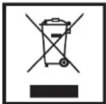
Product

Battery
Note:
The chemical symbol Pb below the battery symbol indicates whether the battery contains lead.
[applicable in countries that have adopted the directive on waste sorting and separation systems]
The AC power supply is controlled by turning on/off the POWER switch on the rear panel. If the product is installed in a place where you cannot easily turn on/off the POWER switch, control the AC power supply by plugging/unplugging the power cord into/from the AC outlet. In this case, install the product as close to the AC outlet as possible, and leave enough space for plugging/unplugging the power cord. If the product is installed in a place where you cannot easily plug/unplug the power cord, equip an easily accessible device to the wiring of the building for turning on/off the power.
- When the product is left unattended and unused for a long period of time, unplug it from the wall outlet and disconnect the cable system.
- Do not overload wall outlets, extension cords, or convenience receptacles on other equipment as this can result in a risk of fire or electric shock.
- Use only the accessory cord designed for this product to prevent shock.
FCC NOTICE (U.S.A. only)
CAUTION: Changes or modifications not approved by JVC could void the user's authority to operate the equipment.
NOTE: This equipment has been tested and found to comply with the limits for a Class B digital device, pursuant to Part 15 of the FCC Rules. These limits are designed to provide reasonable protection against harmful interference in a residential installation. This equipment generates, uses and can radiate radio frequency energy and, if not installed and used in accordance with the instructions, may cause harmful interference to radio communications. However, there is no guarantee that interference will not occur in a particular installation. If this equipment does cause harmful interference to radio or television reception, which can be determined by turning the equipment off and on, the user is encouraged to try to correct the interference by one or more of the following measures:
- Reorient or relocate the receiving antenna.
- Increase the separation between the equipment and receiver.
- Connect the equipment into an outlet on a circuit different from that to which the receiver is connected.
- Consult the dealer or an experienced radio/TV technician for help.
IMPORTANT RECYCLING INFORMATION
This product has a fluorescent lamp that contains mercury. Disposal of these materials may be regulated in your community due to environmental considerations. For disposal or recycling information, please contact your local authorities or for USA, the Electronic Industries Alliance: http://www.eiae.org
Safety Precautions (cont.)
IMPORTANT SAFETY INSTRUCTIONS
- Read all of these instructions.
- Save these instructions for later use.
- Follow all warnings and instructions marked on the product.
- Unplug this product from the wall outlet before cleaning.
Do not use liquid cleaners or aerosol cleaners.
Use a damp cloth for cleaning.
- Do not use this product near water.
- Do not place this product on an unstable cart, stand or table. The product may fall, causing serious damage to the product and persons nearby.
- Slots and openings in the cabinet and the back are provided for ventilation: to ensure reliable operation of the product, these openings must not be blocked by placing the product on a bed, sofa, rug or other similar surface.
This product should never be placed near or over a heat register. This product should not be placed in a built-in installation unless proper ventilation is provided.
- This product should be operated from the type of power source indicated on the marking label.
If you are not sure of the type of power available, consult your dealer or local power company.
- This product is equipped with a 3-wire grounding type plug having a third (grounding) pin.
This is a safety feature.
If you are unable to insert the plug into the outlet, contact your electrician to replace your obsolete outlet.
Do not defeat the purpose of the grounding-type plug.
- Do not allow anything to rest on the power cord. Do not locate this product where persons will walk on the cord.
- If an extension cord is used with this product, make sure that the total of the ampere ratings on the products plugged into the extension cord do not exceed the extension cord ampere rating. Also, make sure that the total of all products plugged into the wall outlet does not exceed 10 amperes.
- Never push objects of any kind into this product through cabinet slots as they may touch dangerous voltage points or short out parts that could result in a risk of fire or electric shock.
Never spill any kind of liquid on the product.
- Do not attempt to service this product yourself, as opening or removing covers may expose you to dangerous voltage points or other risks. Refer all servicing to service personnel.
- Unplug this product from the wall outlet and refer servicing to qualified service personnel under the following conditions.
A. When the power cord or plug is damaged or frayed.
B. If liquid has been spilled into the product.
C. If the product has been exposed to rain or water.
D. If the Product does not operate normally when the operating instructions are followed.
A. When the power cord or plug is damaged or frayed. B. If liquid has been spilled into the product. C. If the product has been exposed to rain or water. D. If the Product does not operate normally when the operating instructions are followed.
Adjust only those controls that are covered by the operating instructions since improper adjustment of other controls may result in damage and will often require extensive work by a qualified technician to restore normal operation.
E. If the product has been dropped or the cabinet has been damaged.
F. If the product exhibits a distinct change in performance, indicating a need for service.
E. If the product has been dropped or the cabinet has been damaged. F. If the product exhibits a distinct change in performance, indicating a need for service.
- The Main Plug is used as the disconnect device. Make enough room for inserting and removing the power plug.
Place the apparatus as close to the outlet as possible.
- Be sure to install the monitor securely to prevent the monitor from falling over, which may cause damage to the monitor or injury.
- Do not step on or hang on the product.

Operating Precautions
The LCD panel and backlight have a limited lifespan. Due to the basic characteristics of the LCD panel, an afterimage or uneven display may occur. It is recommended that you change images occasionally, activate the power saving function, or often turn off the power to reduce the load on the LCD panel. Continuous operation of the LCD panel may accelerate deterioration.
Maintenance
Screen
To avoid irreversible changes in the appearance of the screen, such as uneven color, discoloration, or scratches, be careful about the following:
- Do not paste or stick anything using any glues or adhesive tapes.
- Do not write anything on the screen.
- Do not strike the screen with a hard object.
- Avoid condensation on the screen.
- Do not wipe the screen with any liquid such as water. In addition, wiping the screen with water-diluted neutral detergent or solvents such as alcohol, thinner, or benzine may affect the anti-reflection treatment of the screen.
- Do not wipe the screen forcefully. Wipe stains off the screen with a soft cloth.
Ventilation openings
Use a vacuum cleaner to remove dust around the intakes (all openings). If a vacuum cleaner is not available, use a cloth and wipe it off. Leaving dust around the intakes may prevent proper temperature control and cause damage to the product.
Cabinet
To avoid deterioration or damage to the cabinet, such as peeling paint, be careful about the following:
- Do not wipe the cabinet using solvent such as alcohol, thinner, or benzine.
- Do not expose the cabinet to any volatile substance such as insecticides.
- Do not allow any rubber or plastic in contact for a long time.
- Do not wipe the cabinet forcefully.
Wipe stains off the cabinet with a soft cloth. If the cabinet gets heavily stained, wipe it with a soft cloth soaked in water-diluted neutral detergent and wrung well, then wipe with a soft dry cloth.
Inserting the batteries
Use two AAA dry cell batteries.
Insert the batteries from the end, making sure the and polarities are correct.
- Follow the warnings printed on the batteries.
- Battery life is about six months to one year, depending on how much you use the remote control.
- The batteries we supply are only for setting up and testing your monitor, please replace them as soon as you need to.
- If the remote control does not work properly, replace the batteries.
- Batteries shall not be exposed to excessive heat such, as direct sunshine, fire or the like.

Contents
Safety Precautions....2
Installation....9
Connectors....11
Available Signals....12
Controls 14
Remote Control....15
Indicators....16
OSD Menu....16
How to use External Control (RS-232C) 24
Specifications 26
Trouble Shooting....30
Installation
Precautions
- When installing the monitor on the wall, consult your dealer.
- Route the power cord and connection cables along the floor corners to avoid walking on them.
- For good heat dissipation, try to leave the following distance of space (minimum) around the monitor (see diagram below).
- When installing the monitor near the ceiling or similar location, the remote control may not work correctly because of possible effects, such as reflections, from the surroundings. If this happens, move the monitor where it is free from these effects.
- The ambient temperature of the installation place should be within the range of 0°C to 40°C (32°F to 104°F) (slightly variable depending on the ambient conditions of the installation place).
- Do not install the monitor in such a way that the monitor and other AV equipment affect each other adversely. (For example, if a disturbed image or noise due to electromagnetic interference occurs, or if the infrared remote control malfunctions, change the installation place.)
When installing the monitor on the supplied stand
Unit: mm (inch)
When installing the monitor vertically
- Make sure to install the monitor in the direction illustrated below.
- You can change the position of the JVC logo plate. Remove the sealing sticker on the place for the logo plate and fix the plate with the screws.

Place for the logo plate
Installation (cont.)
How to attach the stand
Fix the stands as illustrated using the supplied screws. Take care not to fix the stands to the wrong side (the foot must face inside).
- Improper use of stands may lead to damages on the floor or on the monitor, or may cause the monitor to topple over.

How to attach the power cord clamp
Fix the power cord clamp as illustrated using the supplied screws at the pointed hole.
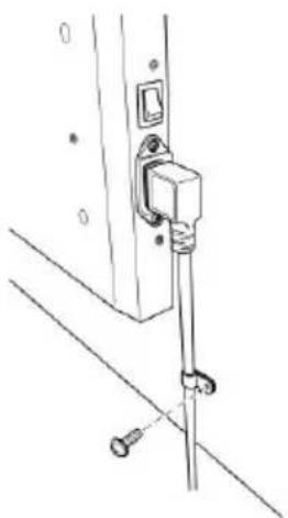
To prevent an accidental fall
Fix the monitor to a wall by using strings.
Fixing the monitor
Attach the hook (not provided) to the rear panel using M8 x 15 mm screws (not provided). Bind the hooks on the rear panel of the monitor to a wall or a pillar using durable string. The holes on the base of the stand are also available to fix the monitor on the platform such as a table using screws (M8).


Available Signals
| Signals | Status Display | VIDEO/ S-VIDEO | RGB | HDMI | SDI | ||
| VIDEO | NTSC | NTSC | ✓ | ||||
| PAL | PAL | ✓ | |||||
| SECAM | SECAM | ✓ | |||||
| BW60 | BW60 | ✓ | |||||
| BW50 | BW50 | ✓ | |||||
| 480/60i | 720x480i | ✓(SD) | |||||
| 576/50i | 720x576i | ✓(SD) | |||||
| 480/60i (pixel repetition) | 720x480i | ✓ | |||||
| 576/50i (pixel repetition) | 720x576i | ✓ | |||||
| 480/60p | 720x480 | ✓ | |||||
| 576/50p | 720x576 | ✓ | ✓ | ||||
| 720/60p | 1280x720 | ✓ | ✓(HD) | ||||
| 720/50p | 1280x720 | ✓ | ✓(HD) | ||||
| 720/30p | 1280x720 | ✓(HD) | |||||
| 720/25p | 1280x720 | ✓(HD) | |||||
| 720/24p | 1280x720 | ✓(HD) | |||||
| 1080/60i | 1920x1080i | ✓ | ✓(HD) | ||||
| 1080/50i | 1920x1080i | ✓ | ✓(HD) | ||||
| 1080/60p | 1920x1080 | ✓ | ✓ | ✓(3G) | |||
| 1080/50p | 1920x1080 | ✓ | ✓ | ✓(3G) | |||
| 1080/30p | 1920x1080 | ✓(HD) | |||||
| 1080/25p | 1920x1080 | ✓(HD) | |||||
| 1080/24p | 1920x1080 | ✓(HD) | |||||
| 1080/30psF | 1920x1080 | ✓(HD) | |||||
| 1080/24psF | 1920x1080 | ✓(HD) | |||||
| 1080/25psF | 1920x1080 | ✓(HD) | |||||
| Signals | Status Display | Frequency | RGB | DVI-D | HDMI | ||
| Horizontal (kHz) | Vertical (Hz) | ||||||
| PC | 640*400@56Hz | 640x400 | 24.823 | 56.42 | √ | ||
| 640*400@70Hz | 640x400 | 31.475 | 70.10 | √ | |||
| 640*480@60Hz | 640x480 | 31.469 | 59.94 | √ | √ | √ | |
| 640*480@72Hz | 640x480 | 37.861 | 72.81 | √ | |||
| 800*600@60Hz | 800x600 | 37.879 | 60.32 | √ | √ | √ | |
| 1024*768@60Hz | 1024x768 | 48.363 | 60.00 | √ | √ | √ | |
| 1024*768@70Hz | 1024x768 | 56.476 | 70.07 | √ | |||
| 1024*768@75Hz | 1024x768 | 60.023 | 75.03 | √ | |||
| 1024*768@85Hz | 1024x768 | 68.667 | 85.00 | √ | |||
| 1280*720@60Hz | 1280x720 | 44.820 | 60.00 | √ | √ | √ | |
| 1280*768@60Hz | 1280x768 | 47.760 | 59.99 | √ | √ | √ | |
| 1360*768@60Hz | 1360x768 | 47.396 | 60.02 | √ | √ | √ | |
| 1152*864@75Hz | 1152x864 | 67.500 | 75.00 | √ | |||
| 1280*1024@60Hz | 1280x1024 | 63.981 | 60.02 | √ | √ | √ | |
| 1400*1050@60Hz | 1400x1050 | 64.744 | 59.95 | √ | √ | √ | |
| 1400*1050@60Hz | 1400x1050 | 65.317 | 59.98 | √ | √ | √ | |
| 1600*1200@60Hz | 1600x1200 | 75.000 | 60.00 | √ | √ | √ | |
* Some signals may not be displayed normally even if its frequency is within the acceptable range. * When the frequency of a non-registration signal is very near to a registration signal, displays the frequency of a registration signal on OSD.
Controls

1. Power Button
- Press the button to turn on or stand-by the monitor.
2. INPUT Button
- Press the button, displays "INPUT SELECT MENU". Select by INPUT button or UP / DOWN buttons, press MENU button.

GM-552

GM-552D
3. UP / DOWN Button
- Press UP button once time, displays "VOLUME MENU".

Adjusts the volume (00-100) by UP/DOWN button.
Press DOWN button once on VIDEO/S-VIDEO input, displays "(INFORMATION) FREEZE" and freezes the picture. Press any button to release freeze.

* Depending on the scene, the motion picture may not freeze completely.
- Press DOWN button once on RGB input, displays "(INFORMATION) AUTO ADJUST" and starts AUTO ADJUST.
- Press the buttons to scroll the cursor to the desired item in the OSD menu.

4. MENU / OK Button
- Press the button to pop up the OSD main menu. The enter key is used for the selected function. Continue to press for over 3 seconds, displays "(INFORMATION) KEY LOCK" and becomes KEY-LOCK.
- Press for over 3 seconds again, displays "(INFORMATION) KEY UN-LOCK" and releases KEY LOCK.


Remote Control
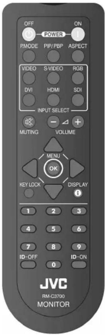
| KEY Comment | ||
| OFF (POWER) Stand-by | ||
| ON (POWER) Power on | ||
| P.MODE *1 | PICTURE mode changes.(USER→CCTV1→CCTV2→STUDIO→USER) | |
| PIP/PBP | PIP/PBP mode changes(OFF→PIP→PBP→OFF) refer to P.19 | |
| ASPECT | Picture size changes refer to P.18(FULL→REGULAR→REAL DOT→FULL) | |
| INPUT SELECT | VIDEO | VIDEO input signal displays. |
| S-VIDEO | S-VIDEO input signal displays. | |
| RGB RGB input signal displays. | ||
| DVI DVI input signal displays. | ||
| HDMI HDMI input signal displays. | ||
| SDI SDI input signal displays. | ||
| MUTING AUDIO Mute on/ off | ||
| +(VOLUME) Volume up | ||
| -(VOLUME) Volume down | ||
| UP | Cursor moves UPVOLUME up (Refer to P.14 No.3) | |
| LEFT Cursor moves Left | ||
| MENU(OK) MENU OSD display / OK | ||
| RIGHT Cursor moves Right | ||
| DOWN | Cursor moves downVOLUME down /AUTO ADJUST(Refer to P.14 No.3) | |
| KEY LOCK | Lock/Unlock Control key and Remote control. | |
| DISPLAY | STATUS display on/off.(INPUT mode and SIGNAL informations) | |
| ID-OFF | Release the specified ID remote control.Refer to P.22 "ID number". | |
| ID-ON | Enter the specified ID remote control.Refer to P.22 "ID number". | |
| Numbers (0-9) S | Select ID number directly. | |
*1: Cannot be selected on RGB, DVI, HDMI (DVI signal).
Indicators

LED identification
Unlit - Power off (AC POWER SW off or AC plug is not connected.)
Green - Power on
Orange - Power off (Standby)
Flash Orange: POWER SAVING mode refer to P.23
Flash Green: Freeze status refer to P.14
OSD Menu
MAIN MENU
Press + or - to select an item, and then press MENU to confirm the selection. When finished, close by EXIT menu. (To fix, must finish by EXIT menu.)
VIDEO/S-VIDEO/DVI/HDMI/SDI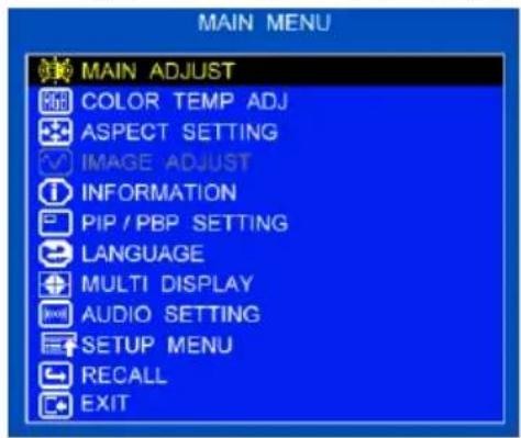
RGB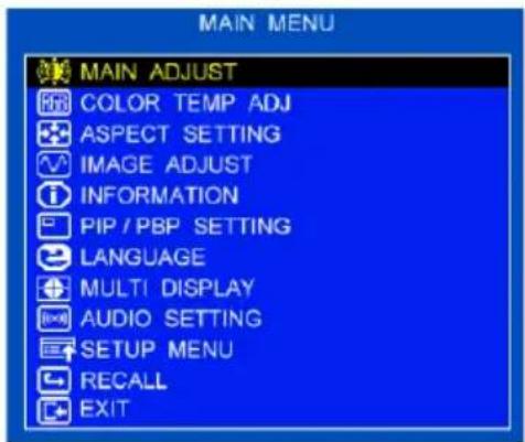
- Press Up / Down buttons to select an icon
- Press MENU button to enter
- Press Up / Down buttons to adjust value
- Press MENU button to return
- Return to MAIN MENU by EXIT
OSD Menu (cont.)

PICTURE MODE: Select the PICTURE MODE. (USER/CCTV1/CCTV2/STUDIO)
USER: Available to adjust the picture setting.
CCTV1/CCTV2/STUDIO: Fixed value.

BACK LIGHT: Adjust the backlight value. (00 - 100)

BRIGHTNESS: Adjust the brightness value. (00 - 100)

CONTRAST: Adjust the contrast value. (00 - 100)

SHARPNESS: Adjust the sharpness value. (00 - 100)

SATURATION: Adjust the saturation value. (00 - 100)

TINT: Adjust the tint value. (00 - 100)

3D COMB: Select the 3D Comb filter status. (ENABLE / DISABLE)

NR: Select the Noise reduction level. (OFF / LOW / HIGH)

EXIT: Press MENU button to return to the main menu.
(To fix, must finish by EXIT menu.)
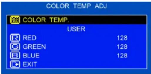
COLOR TEMP ADJ
Set the color temperature of the LCD.
- Press Up / Down buttons to select an icon
- Press MENU button to enter
- Press Up / Down buttons to adjust value
- Press MENU button to return
- Return to MAIN MENU by EXIT

COLOR TEMP. : Select the color temperature. (USER/6500/9300/11500)

RED : Adjust the "RED" value 00 - 255 for user mode.

GREEN : Adjust the "GREEN" value 00 - 255 for user mode.

BLUE : Adjust the "BLUE" value 00 - 255 for user mode.

EXIT : Press MENU button to return to the main menu.
(To fix, must finish by EXIT menu.)
OSD Menu (cont.)
ASPECT SETTING
Press MENU button to select the sub-menu.

- Press Up / Down buttons to select an icon
- Press MENU button to enter
- Press Up / Down buttons to adjust value
- Press MENU button to return
- Return to MAIN MENU by EXIT

ASPECT : Select aspect mode. (FULL / REGULAR / REAL DOT)
FULL : Displays in full area.
REGULAR : Displays the regular size.
REAL DOT : Displays by the original resolution.
*When the resolution of input signal is bigger than the panel pixell, don't display.

EXIT : Press MENU button to return to the main menu.
(To fix, must finish by EXIT menu.)
IMAGE ADJUST (RGB only)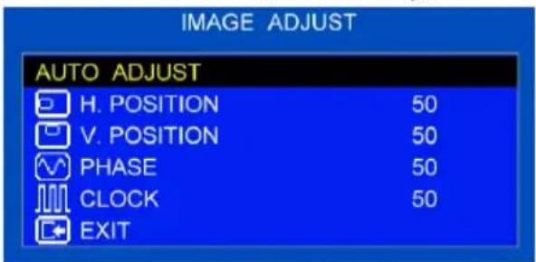
- Press Up/Down buttons to select an icon
- Press MENU button to enter
- Press Up/Down buttons to adjust value
- Press MENU button to return
- Return to MAIN MENU by EXIT
AUTO ADJUST: Press MENU buttons to adjust automatically
H-Position, V-Position, Phase, Clock.

H-POSITION: Adjust the "horizontal position" value 00-100.

V-POSITION: Adjust the "vertical position" value 00-100.

PHASE: Adjust the "PHASE" value 00-100.

CLOCK: Adjust the "CLOCK" value 00-100.

EXIT: Press MENU button to return to the main menu.
(To fix, must finish by EXIT menu.)
* May not be able to select value until 100 in a few kinds of signals.
INFORMATION
Press MENU button to get the timing information.

OSD Menu (cont.)
PIP / PBP SETTING
Displays the sub picture additionally on the main picture.

PIP (Picture in Picture)
| A | B |
PBP (Picture by Picture)

- Press Up/Down buttons to select an icon.
- Press MENU button to enter.
- Press Up/Down buttons to adjust value.
- Press MENU button to return.
- Return to MAIN MENU by EXIT.

PIP/PBP: Select the style of sub picture. (OFF/PIP/PBP)

SOURCE: Select the sub picture input source.
The combination of PIP and PBP is:
- Main screen is one of (RGB, DVI, HDMI, SDI) and PIP or PBP screen is one of (VIDEO, S-VIDEO).
- Main screen is one of (VIDEO, S-VIDEO) and PIP or PBP screen is one of (RGB, DVI, HDMI, SDI).

LOCATION: Select the "PIP LOCATION" value 0 - 3.


RATIO: Select the "PIP size" value 0 - 2.


EXIT: Press MENU button to return to the main menu.
(To fix, must finish by EXIT menu.)
OSD Menu (cont.)
LANGUAGE

- Press Up/Down buttons to select an icon
- Press MENU button to enter
- Return to MAIN MENU by EXIT
MULTI DISPLAY
Example of the Multi Display setting.
When "MULTI SIZE" is set to "2-2" and "MULTI POSITION" is set to "2".
When "MULTI SIZE" is set to "4-4" and "MULTI POSITION" is set to "10".


- Press Up/Down buttons to select an icon
- Press MENU button to enter
- Press Up/Down buttons to adjust value
- Press MENU button to return
- Return to MAIN MENU by EXIT

MULTI SIZE : Select size (OFF/2x1/2x2/3x3/4x4/5x5).

MULTI POSITION: Set the "MULTI POSITION" 01 - 25.
SEAMLESS: Look like seamless on Multi Display. (OFF/ON)

EXIT: Press MENU button to return to the main menu.
(To fix, must finish by EXIT menu.)
AUDIO SETTING

Select SDI input (GD-552D only)

Select the others
- Press Up / Down buttons to select an icon
- Press MENU button to enter
- Press Up / Down buttons to adjust value
- Press MENU button to return
- Return to MAIN MENU by EXIT

VOLUME: Adjust the "VOLUME" value 00 - 100.

MUTING: Select the audio muting function ON/OFF.
HDMI AUDIO: Select HDMI AUDIO (DIGITAL/AUDIO1)
DIGITAL: Output the digital audio signal on HDMI.
AUDIO1: Output the input signal of AUDIO1 (Stereo mini jack).

8CH SOURCE L / R: (GM-552D only)
Select each output in SDI embedded audio channel.
(CH1 - CH8)

EXIT: Press MENU button to return to the main menu.
(To fix, must finish by EXIT menu.)
OSD Menu (cont.)
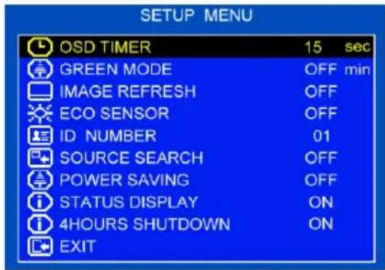
SETUP MENU
- Press Up/Down buttons to select an icon
- Press MENU button to enter
- Press Up/Down buttons to adjust value
- Press MENU button to return
- Return to MAIN MENU by EXIT

OSD TIMER: Adjust the "OSD TIMER" value 5 sec - 30 sec.

GREEN MODE: Select the "GREEN MODE" function OFF/5 min - 10 min.
The luminance of the backlight reduces to 80% after 5 min - 10 min. Press any button to release GREEN MODE.

IMAGE REFRESH: Select the "IMAGE REFRESH" function ON/OFF.
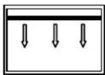
A horizontal black bar scrolls from the top to the bottom every hour. This function protects against image retention (ghosting).

ECO SENSOR: Select the "ECO SENSOR" function ON/OFF.
Automatically adjusts the screen brightness according to the room's brightness.
*When ECO SENSOR is selected, GREEN MODE becomes OFF.

ID NUMBER: Select "ID NUMBER" 01 - 99.
This number is used for specified adjustment with the IR remote control. You can control only the target monitor among many monitors.
*Example of using the specified adjustment with the IR remote control.
- Set ID number "05" in this menu.
- Press "ID-ON" on the IR remote control. ID number "ID: 05" displays on a blue background. You cannot operate the remote control except for the number buttons at this time.
- Press buttons "0" + "5" + "MENU" on the IR remote control.
The back color of the ID number changes to orange. At this time, the device can still be operated normally via remote control. Pressing another number will not work, and the back color will change to blue.
- If you press "ID-OFF", the specified adjustment is released.
OSD Menu (cont.)

SOURCE SEARCH: Select the "SOURCE SEARCH" function ON or OFF.
When no signal is coming in, the device searches for other input signals.

POWER SAVING: Select the "POWER SAVING" function ON or OFF.
- When no signal is coming in, the device enters "POWER SAVING mode" after about 10 seconds. The LED indicator flashes orange. When the signal is recovered, the "POWER SAVING" mode is released.
- If you wish to release "POWER SAVING" mode when there is no signal, press the POWER button, the INPUT SELECT button, or the REMOCON's POWER ON button.
SDI
- When no signal is coming in, the device enters "Stand-by mode" after about 10 seconds. The LED indicator is orange.

STATUS DISPLAY: Displays the status on the left-upper corner when turning on or changing the input signal.

4HOUR SHUTDOWN:
Set the monitor to turn into Stand-by mode when no operation continues for about 4 hours. If you intend to use it for more than 4 hours, change the setting to "OFF".

EXIT: Press the MENU button to return to the main menu.
(To fix, you must finish by using the EXIT menu.)
RECALL
Becomes default condition by the same input signal.
How to Use External Control (RS-232C)
How to Use Serial Communication
- You can control a monitor with external control equipment (a personal computer or a dedicated controller) via the RS-232C terminal.
- Consult your dealer for details of the external control specification.
| Input terminal | Cable | Terminal specification | Communication specifications |
| RS-232C | A straight cable with a RS-232C connector (male for the monitor, female for the external control equipment). | See P.29 | Baud Rate: 4800 bpsData Bits: 8 bitsParity: No parityStop Bits: 1 bitFlow Control: No controlCommunication Code: ASCII Code |
When the monitor is turned on, the external control is not ready.
To start communication, send the connection command from the external control equipment.
To terminate the communication, send the termination command from the external control equipment.
Example of communication procedures:![graph LR A["External control equipment"] --> B["① Starting the communication: connection command (!00BCN1Cr)"] A --> C["② Monitor's status (@00BOKCr)"] A --> D["③ Selecting the Input VIDEO (!00BINACr)"] A --> E["④ Monitor's status (@00BOKCr)"] A --> F["⑤ Terminating the communication: termination co…](/content/2026/06/1294116/images/0684bc3966271b78b5a7e010bf26aca60a69b1fb478a7c0a86286a4b30b32ced.jpg)
* Commands starting with "!" are operation commands from the external control equipment. For details, see on the right. * Commands starting with "@" are status returns from the monitor.
How to Use External Control (RS-232C) (cont.)
| No. | Commands | Functions | Data |
| 1* | !** B C N 1 Cr | Starts communication(connection) | No data |
| 2* | !** B C N 0 Cr | Terminates communication (termination) | No data |
| 3 | !00 B I D S E T x x Cr | Assigns the control ID | 01-99 |
| 4 | !** B I D R E T Cr | Initializes the control ID | No data |
| 5 | !** B I D D S P x x Cr | Displays/hides the ID | 00: Hide, 01: Display |
| 6 | !** B I D C H K x x Cr | Flashes/hides the selected ID No. of the monitor | 00: Hide, 01: Flash |
| 7 | !** B M E N U Cr | Displays the MAIN MENU/Quits the menu operation | No data |
| 8 | !** B U P Cr | Moves the cursor upward (▲) | No data |
| 9 | !** B D O W N Cr | Moves the cursor downward (▼) | No data |
| 10 | !** B A D J R Cr | Makes setting/adjustment (▶) | No data |
| 11 | !** B A D J L Cr | Makes setting/adjustment (◀) | No data |
| 12 | !** B S E T U P Cr | Displays the SET-UP MENU | No data |
| 13* | !** B P W 1 Cr | Turns on the monitor | No data |
| 14 | !** B P W 0 Cr | Turns off the monitor | No data |
| 15 | !** B I N A Cr | Selects Input VIDEO | No data |
| 16 | !** B I N B Cr | Selects Input RGB | No data |
| 17 | !** B I N C Cr | Selects Input DVI | No data |
| 18 | !** B I N D Cr | Selects Input S-VIDEO | No data |
| 19 | !** B I N E Cr | Selects Input HDMI | No data |
| 20 | !** B I N F Cr | Selects Input SDI | No data |
| 21 | !** B D I S P Cr | Displays the status | No data |
| 22 | !** B V P L S Cr | Turns the volume up | No data |
| 23 | !** B V M N S Cr | Turns the volume down | No data |
| 24 | !** B V O L x x x Cr | Adjusts the volume | 00-100 |
| 25 | !** B A M U T E x x Cr | Turns muting on/off | 00: Off, 01: On |
| 26 | !** B A S P T Cr | Changes the aspect ratio | No data |
| 27 | !** B P I C M O D x x Cr | Selects the picture mode | 00: ----01: ----02: USER03: CCTV104: CCTV205: STUDIO |
| 28 | !** B P I P P P B P x x Cr | Selects the sub picture display | 00: Off01: PIP02: PBP |
• These commands can be used while the monitor is on standby.
- "* *" substitutes the ID number of the monitor. The initial setting is "00". When 2 or more monitors are connected and controlled, the commands for the ID "00" control all the monitors.
- Enter the appropriate data to "x", "xx" or "xxx."
- “Cr” is 0Dh.
Specifications
| MODEL NAME | GM-552 / GM-552D |
| TYPE | LCD DISPLAY MONITOR |
| Screen Size | 54.6 (inch) |
| LCD Panel | TFT active matrix |
| Effective screen size | 1209.6 mm (47 5/8") (H) x 680.4 mm (25 3/4")(V) |
| Resolution | 1920x1080 |
| Pixel Pitch | 0.21 mm(H) x 0.63 mm(W) |
| Panel brightness(TYP.) | 450 cd/m2 |
| Contrast ratio(TYP.) | 4000:1 |
| Aspect ratio | 16:9 |
| Viewing angle(TYP.) | 178° (Horizontally) / 178° (Vertically) |
| Display color | 1073.7 million |
| Response time(G to G) | 6.5 msec |
| Audio output | 1.5 W+1.5 W (nominal) |
| Weight | 32.3 kg (71.1 lbs) (with the stand)31.4 kg (69.1 lbs) (without the stand) |
| External dimensions | (with the stand) (without the stand)Width: 1272.6 mm (50 1/8") 1266.6 mm (49 7/8")Height: 745.5 mm (29 3/8") 741.4 mm (29 1/4")Depth: 360.0 mm (14 1/4") 75.7 mm (3") |
| Power requirements | AC 100 V - 240 V, 50 Hz-60 Hz |
| Rated input current | 1.8 A |
| Operating conditions | Temperature: Operating: 0 °C to + 40 °CStorage: -20 °C to + 60 °CHumidity: Operating: 20 % to 85 %(non-condensing) Storage: 10 % to 95 % |
Accessories: Remote Control (RM-C3700) x 1
Batteries (AAA) x 2
Power Cord 1.8 m x 2 (continental & UK for Europe model)
1.8 m x 1 (for US model)
Power cord clamp x 1
with Screw (M3 x 10 mm) x 1
Stand Unit Stand x 2
with Screws (Flat head M4 x 12 mm) x 4
Screws (Truss head M4 x 12 mm) x 2
Covering sticker x 1
Specifications (cont.)
Signal Characteristics
| VIDEO | : 1.0 V(p-p), automatic switching from 75 Ω unbalanced termination to Hi-Z with loop-through operation. | |
| S-VIDEO | Y | : 1.0 V(p-p) 75 Ω unbalanced termination. |
| C | : Burst levelNTSC 0.286V(p-p) 75 Ω unbalanced termination.PAL/SECAM 0.3 V(p-p) 75 Ω unbalanced termination. | |
| RGB | R,G, B | : 0.7 V(p-p) 75 Ω unbalanced termination. |
| SYNC | : TTL (positive/negative) | |
| DVI-D | : DVI-D signal | |
| HDMI | : HDMI signal | |
| SDI(GM-552D Only) | : (3G-SDI) SMPTE424M / SMPTE425M LEVEL A-1(HD-SDI) BTA S004C / SMPTE292M(SD-SDI) ITU-R BT.656 / SMPTE259M(EMBEDDED AUDIO) SMPTE299M / SMPTE272M | |
| Analog AUDIO | : 500 mV(rms). | |
| RS232C | : "How to use the serial communication" on page 24. | |
| DC OUT | : DC +12 V output Max. 350 mA |
- For easy understanding, pictures and illustrations are shown by being emphasized, omitted or composed, and may be slightly different from actual products.
- Design and specifications are subject to change without notice.
- All company names and product names mentioned herein are used for identification purposes only, and may be the trademarks or registered trademarks of their respective companies.
- HDMI, the HDMI Logo, and High-Definition Multimedia Interface are trademarks or registered trademarks of HDMI Licensing LLC in the United States and other countries.
Specifications (cont.)
Dimensions: Screw size: 8-M8, depth: 15 mm (VESA standard) [Unit: mm (inch)]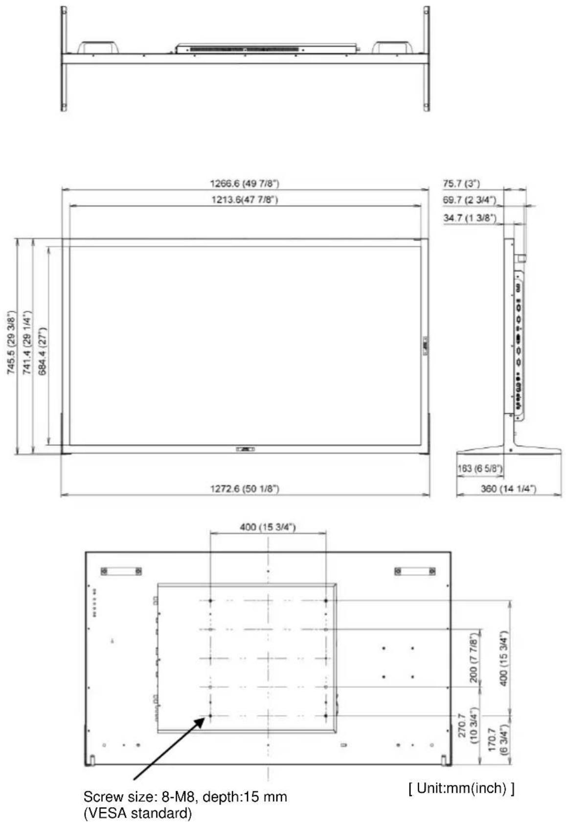
Specifications (cont.)
Specification of Terminals
Specifications of the DVI-D terminal

| Pin No. | Signal name | Pin No. | Signal name | Pin No. | Signal name |
| 1 | T.M.D.S Data 2- | 9 | T.M.D.S Data 1- | 17 | T.M.D.S Data 0- |
| 2 | T.M.D.S Data 2+ | 10 | T.M.D.S Data 1 + | 18 | T.M.D.S Data 0+ |
| 3 | T.M.D.S Data 2/4 shield | 11 | T.M.D.S Data 1/3 shield | 19 | T.M.D.S Data 0/5 shield |
| 4 | NC | 12 | NC | 20 | NC |
| 6 | NC | 13 | NC | 21 | NC |
| 6 | DDC Clock | 14 | +5 V Power | 22 | T.M.D.S Clock shield |
| 7 | DDC Data | IS | GND | 23 | T.M.D.S Clock+ |
| 8 | NC | 16 | Hot Plug Detect | 24 | T.M.D.S Clock- |
Specifications of the RGB IN terminal

| Pin No. | Signal name | Pin No. | Signal name |
| 1 | Red | 9 | +5 V |
| 2 | Green | 10 | GND |
| 3 | Blue | 11 | GND |
| A | — | 12 | DDC Data |
| 5 | GND | 13 | HD |
| 6 | GND | 14 | VD |
| 7 | GND | 15 | DDC Clock |
| 8 | GND | External | GND |
Specifications of the Y/C terminal
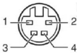
Connect it to the S-video output terminal.
| Pin No. | Input signal |
| 1 | GND (Y) |
| 2 | GND (C) |
| 3 | Y |
| 4 | C |
Specifications of the RS-232C terminal

This is a female terminal.
| Pin No. | Signal |
| 1 | — |
| 2 | RD (Receive Data) |
| 3 | TD (Transmit Data) |
| A | |
| 5 | GND (Ground) |
| 6 | — |
| 7 | RTS |
| 8 | CTS |
| 9 | — |
• The 7th terminal and the 8th terminal are connected.
Troubleshooting
Solutions to common problems related to the monitor are described here.
If none of the solutions presented here solves the problem, unplug the monitor and consult an authorized dealer or service center.
| Symptom | Probable cause and corrective action | Page |
| No power supply | · Firmly insert the AC power plug. | 11 |
| No picture with the power on | · Select the correct input with INPUT SELECT buttons.· Connect the signal cable firmly.· Turn on the power of the connected component and set the output correctly.· Check if the input signal format is acceptable on the monitor. | 11,1213,14 |
| No sound | · Adjust the volume level.· Select MUTING OFF by AUDIO SETTING menu or Press MUTING button on REMOCON.· Connect the signal cable firmly.· Turn on the power of the connected component and set the output correctly. | 15,21 |
| “NO SYNC” appears. | · Select the correct input with INPUT SELECT buttons.· Connect the signal cable firmly.· Turn on the power of the connected output video signals. Or, check if the video output of the component (video output setting of the VCR or graphic board of the computer) is set correctly. | 11 |
| Wrong color | · Adjust the items of “COLOR TEMP ADJ.”. | 17 |
| The picture becomes blurred. | · Adjust the picture contrast or brightness by using the adjustment buttons on the front panel. | 17 |
| Buttons on the monitor do not work. | · Set “KEY UN-LOCK” in OSD MENU or push KEY LOCK on REMOTE CONTROL. | 14,15 |
Note
- LCD DISPLAY MONITOR
- GM-552/GM-552D INSTRUCTIONS
- SAFETY PRECAUTIONS
- IMPORTANT SAFEGUARDS
- POWER CONNECTION
- WARNING
- NOTE FOR UNITED KINGDOM POWER CORD ONLY
- HOW TO REPLACE THE FUSE
- SAFETY PRECAUTIONS (CONT.)
- UNDER THE FOLLOWING CONDITIONS
- EUROPEAN UNION ONLY
- DEAR CUSTOMER
- INFORMATION FOR USERS ON DISPOSAL OF OLD EQUIPMENT AND BATTERIES
- [EUROPEAN UNION]
- [BUSINESS USERS]
- [OTHER COUNTRIES OUTSIDE THE EUROPEAN UNION]
- INFORMATION FOR USERS ON DISPOSAL OF OLD EQUIPMENT
- [APPLICABLE IN COUNTRIES THAT HAVE ADOPTED THE DIRECTIVE ON WASTE SORTING AND SEPARATION SYSTEMS]
- FCC NOTICE (U.S.A. ONLY)
- IMPORTANT RECYCLING INFORMATION
- IMPORTANT SAFETY INSTRUCTIONS
- OPERATING PRECAUTIONS
- MAINTENANCE
- SCREEN
- VENTILATION OPENINGS
- CABINET
- INSERTING THE BATTERIES
- CONTENTS
- INSTALLATION
- PRECAUTIONS
- WHEN INSTALLING THE MONITOR VERTICALLY
- INSTALLATION (CONT.)
- HOW TO ATTACH THE STAND
- HOW TO ATTACH THE POWER CORD CLAMP
- TO PREVENT AN ACCIDENTAL FALL
- FIXING THE MONITOR
- CONTROLS
- POWER BUTTON
- INPUT BUTTON
- UP / DOWN BUTTON
- MENU / OK BUTTON
- REMOTE CONTROL
- INDICATORS
- LED IDENTIFICATION
- OSD MENU
- MAIN MENU
- OSD MENU (CONT.)
- COLOR TEMP ADJ
- ASPECT SETTING
- INFORMATION
- PIP / PBP SETTING
- LANGUAGE
- MULTI DISPLAY
- AUDIO SETTING
- SELECT SDI INPUT (GD-552D ONLY)
- SELECT THE OTHERS
- SETUP MENU
- SDI
- HOUR SHUTDOWN
- RECALL
- HOW TO USE EXTERNAL CONTROL (RS-232C)
- HOW TO USE SERIAL COMMUNICATION
- HOW TO USE EXTERNAL CONTROL (RS-232C) (CONT.)
- SPECIFICATIONS (CONT.)
- SPECIFICATION OF TERMINALS
- SPECIFICATIONS OF THE RGB IN TERMINAL
- TROUBLESHOOTING
- NOTE
Brand : JVC
Model : GM-552D
Category : Monitor