
AC-S7 - Air conditioner AKIRA - Free user manual and instructions
Find the device manual for free AC-S7 AKIRA in PDF.


| Product Type | Portable Air Conditioner |
| Model | AC-S7 |
| Brand | Akira |
| Cooling Capacity (BTU/h) | 7000 |
| Heating Function | No (Cooling only) |
| Energy Efficiency Ratio (EER) | 2.6 |
| Power Supply | 220-240 V / 50 Hz |
| Power Consumption (Cooling) | 800 W |
| Air Flow (High) | 300 m³/h |
| Dehumidification Capacity | 1.0 L/h |
| Noise Level (High) | 52 dB(A) |
| Dimensions (W x H x D) | 450 x 700 x 380 mm |
| Weight (Net) | 28 kg |
| Refrigerant | R290 |
| Modes | Cool, Fan, Dehumidify, Sleep |
| Timer | 24-hour on/off |
| Remote Control | Yes (with LCD display) |
| Casters | Yes (4 swivel casters) |
| Filter Type | Washable mesh filter |
| Condensation Management | Auto evaporation (no bucket required) |
| Installation Kit Included | Window sealing plate and hose |
| Safety Features | Overheat protection, auto restart after power failure |
| Cleaning and Maintenance | Clean filter every 2 weeks; wipe exterior with damp cloth |
| Repairability | Spare parts available through authorized service centers |
Frequently Asked Questions - AC-S7 AKIRA
User questions about AC-S7 AKIRA
0 question about this device. Answer the ones you know or ask your own.
Ask a new question about this device
Download the instructions for your Air conditioner in PDF format for free! Find your manual AC-S7 - AKIRA and take your electronic device back in hand. On this page are published all the documents necessary for the use of your device. AC-S7 by AKIRA.
USER MANUAL AC-S7 AKIRA
Refrigeration cycle 10
Operation details 12
Installation 22
2-way, 3-way valve ....33
Trouble shooting 41
Exploded drawing 49
Part list 52
CHAPTER 1: FEATURES
| MODE | DESCRIPTION |
| COOLING | Cools, dehumidifies and filters the room air. Maintains desired room temperature. |
| HEATING | Heats and filters the room air. Maintains desired room temperature. |
| SMART | Operates the appliance at COOLING, HEATING or DRY mode, maintaining desired temperature dependent upon the room temperature. |
| DRY | Dehumidifies and softly cools the room air. This mode is advisable to be used when the room temperature is rather cool but the humidity is rather high. |
| FAN ONLY | Re-circulates and filters the room air. Maintains constant air movement in the room. |
| SLEEP | The SLEEP mode will be canceled after being set for 8 hours. The set temperature will be increased 0.5^ per hour during the first two hours in COOLING or DRY and decreased 1^ per hour in the first three hours in HEATING. |
| AUTO FAN | The appliance automatically selects the indoor fan speed in accordance to the room temperature. At the start, the appliance operates at high fan speed. As the room temperature gets closer to the set temperature, the fan switches to a lower speed for quieter operation. |
| FAN SPEED HIGH MEDIUM LOW | 1. The appliance can set at different indoor fan motor speed by pressing the FAN SPEED button on the remote controller.2. When this symbol is being displayed on the LCD of the remote controller, the signal is transmitting from the remote controller to the air conditioner. |
| TEMP. SET UP DOWN | Press DOWN button once, the set temperature is decreased by 1^ .Press UP button once, the set temperature is increased by 1^ . |
| TIMER | Automatically switches the appliance ON at preset time intervals, ensuring a comfortable environment before you return home, or switches OFF the appliance automatically when you sleep without wasting electricity. |
| Auto -restart | When the power supply restores after its failure, the machine will start to work automatically with the previous setting parameters. |
| SUPER | Strong cooling when you just come into your room and want to cool the room as soon as possible. |
CHAPTER 2: SPECIFICATIONS
(SEE APPENDIX A)
● The preset temperature of the appliance ranges from 16 to 32°C.
- The ambient temperature of the cooling only air conditioner ranges from 18°C to 43°C.
- The ambient temperature of the heat pump ranges from -7^ to 43^ .
● The rated cooling operation test condition is as following.
Indoor DB/WB temperature: 27°C /19°C
outdoor DB/WB temperature: 35°C /24°C
● The rated heating operation test condition is as following.
● indoor DB/WB temperature: 20 /Max.15°C
● outdoor DB/WB temperature: 7°C /6°C
2. TEMPERATURE RANGE FOR T3 CLIMATE AIR CONDITIONER
● The preset temperature of the appliance ranges from 18^ C to 32^ C.
- The ambient temperature of the cooling only air conditioner ranges from 21°C to 52°C.
● The rated cooling operation test condition is as following.
Indoor DB/WB temperature: 27°C /19°C
outdoor DB/WB temperature: 35°C /24°C
3. REFRIGERANT PIPING
- The maximum length of the connecting refrigerant piping between indoor unit and outdoor unit is 15m and the maximum elevation difference between indoor and outdoor units are 5m.
- If the refrigerant piping is longer than 7m, additional refrigerant charge 20g/m for below 1/2 inch gas pipe and 30g/m for below 5/8 or 3/4 inch gas pipe is advisable.
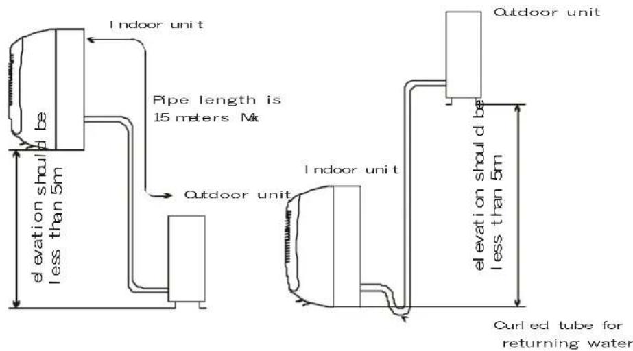
● Outside diameter of the refrigerant piping is as following.
| Models | OD of liquid pipe (small pipe) | OD of gas pipe (large pipe) |
| 7K, 9K (COOLING ONLY & HEAT PUMP) | 6mm or 1/4 inch | 10mm or 3/8 inch |
| 12K, 18K,24K ( COOLING ONLY & HEAT PUMP) | 6mm or 1/4 inch | 12mm or 1/2 inch |
CHAPTER 4: REMOTE CONTROLLER
The remote controller transmits signals to the system.
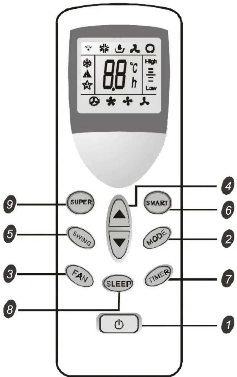
1. ON/OFF BUTTON
- The appliance will be started when it is energized or will be stopped when it is in operation, if you press this button.
2. MODE BUTTON
● Used to select the type of operation mode.
COOLING mode
DRY mode
FAN ONLY mode
HEATING mode
3. FAN SPEED BUTTON
● Used to select the indoor fan motor speed.
Automatic fan speed
High fan speed
Medium fan speed
Low fan speed
4.TEMPERATURE SETTING BUTTON
● Used to adjust the preset room temperature.
● Used to adjust time in TIMER mode.
5. SWING BUTTON
- Press to adjust airflow direction.
6. SMART BUTTON
● Used to enter fuzzy logic operation directly, regardless of the unit is on or off.
7. TIMER SET/CANCEL BUTTON
● Used to set or cancel the timer operation.
8. SLEEP BUTTON
- Used to set or cancel SLEEP mode operation during COOLING, HEATING, DRY or SMART mode operation.
9. SUPER BUTTON
● Used to start or stop the fast cooling.
(Fast cooling operates at high fan speed with 18^ setting temperature automatically)
The indication symbols on LCD:
Indication symbols on LCD:

Super indicator

Smart indicator

Sleep indicator

Signal transmit.

Cooling indicator

Dry indicator

Fan only indicator

Heating indicator

Auto fan speed

High fan speed

Medium fan speed

Low fan speed
1. Cooling only appliance

flowchart
graph TD
    A["evaporator"] --> B["3-way valve"]
    B --> C["liquid side"]
    C --> D["2-way valve"]
    D --> E["condenser"]
    E --> F["capillary"]
    F --> G["compressor"]
    G --> H["accumulator"]
    H --> I["Outdoor unit t"]
    style A fill:#f9f,stroke:#333
    style C fill:#f9f,stroke:#333
    style D fill:#f9f,stroke:#333
    style E fill:#f9f,stroke:#333
    style F fill:#f9f,stroke:#333
    style G fill:#f9f,stroke:#333
    style H fill:#f9f,stroke:#333
    style I fill:#f9f,stroke:#333
2. Heat pump
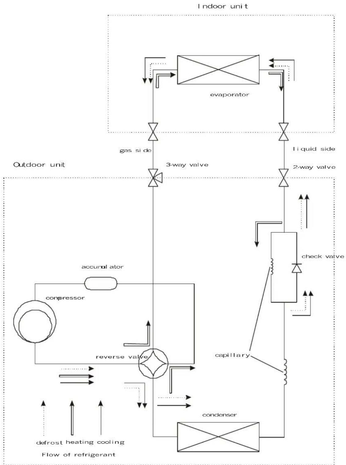
flowchart
graph TD
    A["evaporator"] --> B["liquid side"]
    B --> C["2-way valve"]
    C --> D["check valve"]
    D --> E["capillary"]
    E --> F["condenser"]
    F --> G["confidential"]
    G --> H["reverse valve"]
    H --> I["compressor"]
    I --> J["accural ator"]
    J --> K["gas side"]
    K --> L["3-way valve"]
    L --> M["defrost heating cooling"]
    M --> N["Flow of refrigerant"]
    style A fill:#f9f,stroke:#333
    style B fill:#ccf,stroke:#333
    style C fill:#cfc,stroke:#333
    style D fill:#fcc,stroke:#333
    style E fill:#cff,stroke:#333
    style F fill:#ffc,stroke:#333
    style G fill:#cfc,stroke:#333
    style H fill:#fcc,stroke:#333
    style I fill:#ffc,stroke:#333
    style J fill:#cfc,stroke:#333
    style K fill:#fcc,stroke:#333
    style L fill:#cfc,stroke:#333
    style M fill:#fcc,stroke:#333
    style N fill:#cfc,stroke:#333
CHAPTER 6: OPERATION DETAILS
1. SAFETY CONTROL
● 3 minutes delay for compressor
The compressor is ceased for 3 minutes to balance the pressure in the refrigeration cycle in order to protect the compressor.
● 59 seconds delay for reversing valve
The 4-way reversing valve delay for 59 seconds to prevent the refrigerant abnormal noise when the HEATING operation is OFF or switched to other operation modes.
• Over-current control
The compressor will be switched OFF when it is over-current for 5 seconds, and when the current is normal and the compressor has been stopped for 3 minutes, the compressor will be turned ON.
- Freeze preventive control
When the indoor pipe temperature falls below -1^ during COOLING or DRY operation for 3 minutes, the compressor and outdoor fan motor turn OFF with buzzer 3 beeps. When the indoor pipe temperature recovers to 5^ and the compressor has been stopped for 3 minutes, the compressor and outdoor fan motor will be turned ON.
● Overheating protection system
When overloading occurs during the heating operation, this system controls the outdoor fan motor and compressor according to the indoor pipe temperature to prevent the overloading of the compressor and restrain the rise in high pressure. When the indoor pipe temperature exceeds 53°C, the outdoor fan motor will be turned OFF, and when the indoor pipe temperature falls below 49°C, the outdoor fan motor recovers to ON. When the indoor pipe temperature exceeds 63°C, the appliance will be turned OFF with 4 beeps of buzzer and cannot recover automatically.
2. AIR FLOW DIRECTION CONTROL
- This function is to swing the louver up and down automatically and to set it at a desired position.
● The procedure is as following.
Press the ON/OFF button to operate the appliance. The louver will swing automatically to the default position.
Press the SWING button to swing the louver up and down automatically.
Repress the SWING button to stop the louver at a desired position. - The louver is controlled by a step motor. The different default position of different modes is as following:
The louver can swing from 0° to 110°.
The louver closes at 0°.
The louver swings from 25^ to 65^ with an automatic setting point of 45^ during COOLING operation.
The louver swings from 10^ to 30^ with an automatic setting point of 30^ during DRY operation.
The louver swings from 45^ to 98^ with an automatic setting point of 85^ during HEATING operation.
The louver swings from 45^ to 98^ with an automatic setting point of 85^ during FAN only operation.
- When the COOLING mode operation is selected without setting temperature, the appliance will set the preset temperature at 26 °C automatically with the AUTO FAN speed.
- When selecting the COOLING mode operation, the appliance will operate according to the setting by the remote controller and the operation diagram is as following:
| ROOM TEMP. SET TEMP. +1pe (COMP. ON) SET TEMP. - 1pe (COMP. OFF) | |||||
| More than 3 mins | More than 3 mins | ||||
| Indoor fan motor speed | set speed | set set speed | set speed | speed | set speed |
| Compressor | ON | OFF | ON | OFF ON | |
| Outdoor fan motor | ON | OFF | ON | OFF ON | |
4. DRY MODE OPERATION
- The appliance starts as COOLING operation. If 3 minutes elapses after starting, the appliance will sense the intake air temperature and minus 1.5^ C as the setting temperature.
- During DRY operation, the compressor ON when temperature is the setting temperature plus 1°C. The compressor OFF when temperature is the setting temperature minus 1°C. The setting temperature can only be adjusted by 2°C up and down.
- When the appliance operates at DRY mode, the indoor motor speed is LOW.
● The appliance will operate at the setting by the remote controller and the opera-
tion diagram is shown as following.

line
| Condition | Room Temp (°C) | Indoor fan motor speed | Indoor fan motor speed (%) | |---|---|---|---| | Room Temp (Comp Off) | More than 3 mins | * | set speed | | Room Temp (Comp On) | More than 3 mins | * | set speed | | Indoor fan motor speed | ON | * | set speed | | Indoor fan motor speed | OFF | ON | set speed | | Outdoor fan motor | ON | ON | set speed | | Outdoor fan motor | OFF | ON | set speed | | Room Temp (Comp Off) | A | A | A | | Room Temp (Comp On) | A | B | B | | Indoor fan motor speed | * | * | * | | Indoor fan motor speed | set speed | * | set speed | | Indoor fan motor speed | set speed | * | set speed | | Indoor fan motor speed | set speed | * | set speed | | Indoor fan motor speed | set speed | * | set speed | | Indoor fan motor speed | set speed | * | set speed | | Indoor fan motor speed | set speed | * | set speed | | Indoor fan motor speed | set speed | * | set speed | | Indoor fan motor speed | set speed | * | set speed | The chart displays a line graph with two distinct segments: 'More than 3 mins' at the top and 'Set Speed' at the bottom. The table below is a table for the same data series.* The indoor fan motor is controlled by Cold Air Preventive System
● The indoor fan motor is controlled by Cold Air Preventive System.
6. COLD AIR PREVENTIVE SYSTEM (ONLY AVAILABLE FOR HEAT PUMP)
- This system is intended to prevent cold air from being discharged during HEATING operation.
- The indoor fan motor speed will be controlled as following. (for7K, 9K, 12K, 18K and 22K heat pump)
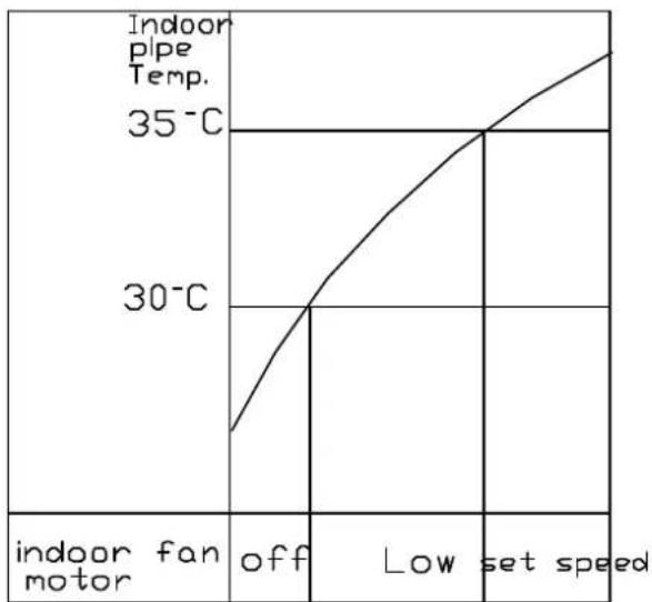
line
| Indoor fan motor | indoor pipe Temp. | | :--- | :--- | | off | 30°C | | Low | 35°C | | set speed | |Indoor pipe temp. rises

line
| Time | Temperature (°C) | | :--- | :--- | | 0 | 30 | | 1 | 28 | | 2 | 25 | | 3 | 22 | | 4 | 18 | | 5 | 14 | | 6 | 10 | | 7 | 8 | | 8 | 6 | | 9 | 4 | | 10 | 2 | | 11 | 1 | indoor fan motor set speed Low offIndoor pipe temp. falls
● The indoor fan motor speed will be controlled as following. (for 24K heat pump)

line
| Indoor fan motor | Indoor pipe Temp. | | :--- | :--- | | off | 25°C | | Low | 35°C | | set speed | 35°C |Indoor pipe temp. rises
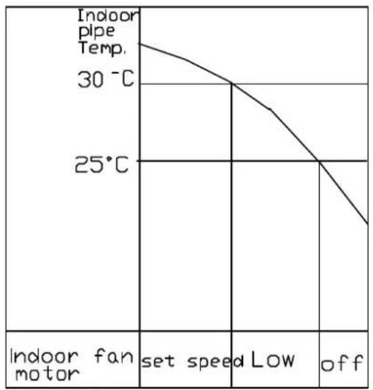
line
| Indoor fan motor | Indoor pipe Temp. | | :--- | :--- | | set speed | 30 °C | | Low | 25 °C | | off | 25 °C |Indoor pipe temp. falls
7. SMART MODE OPERATION
- When SMART air conditioning is selected, the operation mode and preset temperature are set automatically according to the room temperature at starting operation.
● The operation procedure of cooling only is as following.
| Intake air temperature at operation start | Over 26°C Below 26 °C | |
| Preset temperature | 26°C | Intake air temperature minus 1.5°C |
| Operation mode | COOLING | DRY |
*The initial mode will be continued and independent upon the room temperature changing.
● The operation procedure of heat pump is as following.
| Intake air temperature at operation start | Over 26°C | 21 °C ~ 26°C Below | 21 °C |
| Preset temperature | 26°C | Intake air temperature at operation start | 22°C |
| Operation mode | COOLING | DRY | HEATING |
The initial mode will be continued and independent upon the room temperature changing.
- If initial mode is selected, that mode is continued, independent upon the temperature changing.
- The indoor fan motor speed is automatically determined by Auto Fan Speed. If you are not satisfied with the auto fan speed, you can adjust the fan speed by pressing the FAN BUTTON.
8. AUTO FAN SPEED
- When the Auto Fan Speed is selected in COOLING or HEATING operation, the indoor fan motor speed is automatically controlled by the intake air temperature and the preset temperature.
● The operation procedure of COOLING is as following.

line
| Indoor fan motor speed | Low | Medium | High | |---|---|---|---| | Intake air temp | | | | | Set temp+1æ | | | | | Set temp+3æ | | | | | Set temp+3æ | | | |Indoor pipe temperature rises
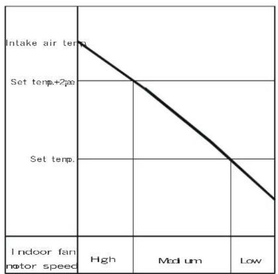
line
| Indoor fan motor speed | High | Medium | Low | |---|---|---|---| | Intake air temp. | | | | | Set temp.+2/ae | | | | | Set temp. | | | | | Indoor fan motor speed | | | |Indoor pipe temperature falls
● The operation procedure of HEATING is as following.

line
| Indoor fan motor speed | Hgh | Medium | Low | |---|---|---|---| | Set temp.2/ae | High | Medium | Low |Indoor pipe temperature rises

line
| Indoor fan motor speed | Low | Medium | High | |---|---|---|---| | Intake air temp. | | | | | Set temp.-1jæ | | | | | Set temp.-3jæ | | | | | Indoor fan motor speed | Low | Medium | High |Indoor pipe temperature falls
9. INDOOR FAN SPEED CONTROL
● Auto Fan Speed control
When set to Auto Fan Speed, the indoor fan motor speed is controlled by the difference between the intake air temperature and the preset temperature. The more the difference, the higher the indoor fan motor speed. Auto Fan Speed is only available for COOLING and HEATING modes.
● Manual fan speed control
Basic fan motor speed adjustment (3 setting, LOW, MEDIUM and HIGH) can be conducted by using the Fan Speed Selection button on the remote controller.
● The indoor fan speed in different modes is shown as following.
| Fan Speed | High(H) | Medium(M) | Low(L) | Stop | |
| COOLING | Manual | OK | OK | OK | N/A |
| Automatic | OK | OK | OK | N/A | |
| HEATING | Manual | OK | OK | OK | N/A |
| Automatic | OK | OK | OK | N/A | |
| Cold Air Preventive | OK | OK | OK | OK | |
| DRY | N/A | N/A | OK | N/A | |
| FAN ONLY | OK | OK | OK | N/A | |
10. EMERGENT START
- If you lose the remote controller or it is out of work, you can also operate the appliance by pressing the EMERGENT BUTTON on the indoor unit for an emergent start.
- The operation mode is SMART if an emergent start is presented when the appliance is connected to the power at first time. If the appliance is in stand by, the operation mode will restore the last time setting when you press the EMERGENT BUTTON.
11. AUTORESTART FUNCTION
When the unit is connected to power, pressing the EMERGENT BOTTON for over 5 seconds;
if the unit without auto restart function, it will be of the function of auto restart after the buzzer 1 beeps;
if the unit with auto restart function, it will discharge the auto restart function after the buzzer 1 beeps.
12. DEFROST
- The defrost timer (integrating the operation time of compressor) counts time by microprocessor during HEATING operation.
- 50 minutes later after starting HEATING operation or after defrost, when the outdoor pipe temperature falls to -8^ , the defrosting is started. When the outdoor pipe temperature exceeds 8^ or the defrosting time reaches 10 minutes, the defrosting is ended.
- During the defrosting operation, the red LED indicator on the indoor unit of the appliance flickers.
- In the defrost operation, firstly the compressor and the outdoor fan motor are turned OFF. 59 seconds later the reversing valve is turned OFF. 60 seconds later the compressor is turned ON.
● The maximum defrost time is 10 minutes. - In the end of defrosting, the compressor is turned OFF, 59 seconds later the reversing valve is turned ON. 60 seconds later the compressor and outdoor fan motor are turned ON and starting HEATING operation.
● During the defrost operation, the indoor fan motor is controlled by Cold Air
Preventive System.
● The HEATING and defrosting operation is alternated as following.

flowchart
graph LR
    A["Switch ON"] --> B["Heating"]
    B --> C["Min 50 nins"]
    C --> D["Heating"]
    D --> E["Min 50 nins"]
    E --> F["Defrosting"]
    F --> G["Max 10 nins"]
    G --> H["Heating"]
    H --> I["Min 50 nins"]
● The defrosting procedure is shown as following.

flowchart
graph TD
    A["Outdoor fan motor"] --> B["ON"]
    C["Reverse valve"] --> D["ON"]
    E["Compressor"] --> F["OFF"]
    B --> G["OFF"]
    D --> H["OFF"]
    F --> I["OFF"]
    G --> J["59S 1S"]
    H --> K["59S 1S"]
    I --> L["59S 1S"]
● The setting time ranges from 0.5 hour to 24 hours.
- OFF-TIMER can be set when the appliance is in operation, and it will be switched OFF when the preset time is achieved.
- ON-TIMER can be set when the appliance is in suspension, and it will be switched ON when the preset time is achieved.
- Pressing TIMER button once, the last setting time display on the LCD of remote controller. You can adjust the setting time by pressing the TEMPERATURE SETTING BUTTON. Pressing the TIMER button again, the timer mode is selected and the yellow LED indicator on the indoor unit lights up.
- The TIMER mode can be cancelled by pressing the TIMER button again on the remote controller.
14. SLEEP MODE OPERATION
- The SLEEP mode can only be set during COOLING,DRY,SMART or HEATING operation.
- An energy conservation operation will be achieved if selecting SLEEP mode combined with OFF-TIMER. The operation will be turned OFF after the preset time. The maximum preset time of SLEEP mode is 8 hours(default time).
- When selecting the COOLING or DRY operation with SLEEP mode, the operation diagram is as following. The setting temperature will be raised by 0.5^ C per hour in the first two hours after the starting. The operation will stop after 8 hours.

- When selecting HEATING operation with SLEEP mode, the setting temperature will be decreased by 3^ during successive 3 hours later. The operation will
stop in 8 hours. The operation diagram is as following.
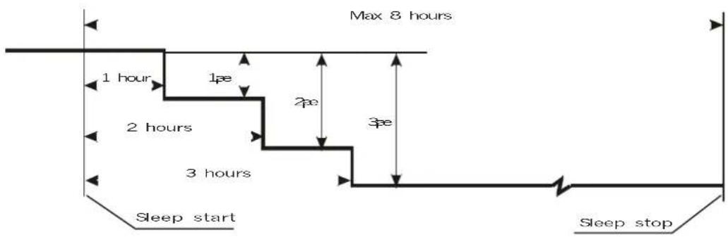
flowchart
graph TD
    A["Max 8 hours"] --> B["1 hour"]
    B --> C["1ae"]
    C --> D["2 hours"]
    D --> E["3 hours"]
    E --> F["3ae"]
    F --> G["Sleep start"]
    G --> H["Sleep stop"]
CHAPTER 7: INSTALLATION
Notice: There is detailed information about installation in the OPERATING AND INSTALLATION INSTRUCTIONS MANUAL. The same information is not repeated in this TECHNICIAN SERVICE MANUAL.
- Indoor unit
There should not be any heat source or steam near the unit.
There should not be any obstacles to prevent the air circulation.
A place where air circulated in the room will be good.
A place being drained can be easily obtained.
A place where noise prevention is taken into consideration.
Do not install the unit near the door way.
Ensure the spaces from the wall, ceiling, fence or other obstacles. -
Outdoor unit
If an awning is built over the unit to prevent direct sunlight or rain exposure, be careful that heat radiation from the condenser is not restricted.
There should not be any animals or plants which could be affected by air discharged.
Ensure the spaces from the wall, ceiling, fence or other obstacles.
A place where noise does not annoy your neighbors. -
DRILL THE PIPING HOLE WITH 70mm DIAMETER HOLE-CORE DRILL
-
Line according to the arrows marked on the lower left and right side of the installation plate.
● The meeting point of the extended line is the center of the hole. - Drill the piping hole at either the right or the left and the hole should be slightly slant to the outdoor side.
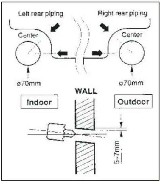
- PIPING AND DRAINAGE OF INDOOR UNIT
● Preparation of piping
1) Cut the pipes and the cable
Use the accessory piping kit or the pipes purchased locally.
Measure the distance between the indoor and the outdoor units.
Cut the pipes a little longer than measured distance.
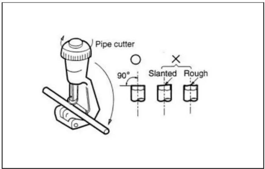
Cut the cable a 1.5m longer than the pipe length.

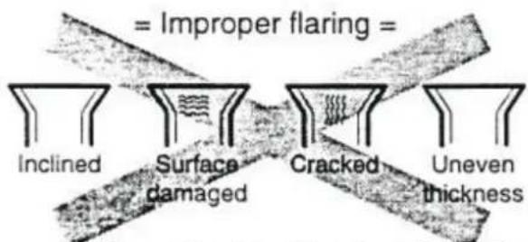
When properly flared, the internal surface flare will evenly shine and be of even thickness. Since the flare part comes into contact with the connectors, carefully check the flare finish.
2) Remove burrs
Remove burrs from cut edges of pipes.
Turn the pipe end down to avoid the metal powder entering the pipe.
Caution: If the burrs are not removed, they may cause a gas leakage.
3) Flaring the pipes
Insert the flare nuts, mounted on the connection ports of both indoor and outdoor units, onto the copper pipes. Some refrigerant gas may leak, when the flare nuts are removed from the indoor unit, as some gas is charged to prevent the inside of the pipe from rusting.
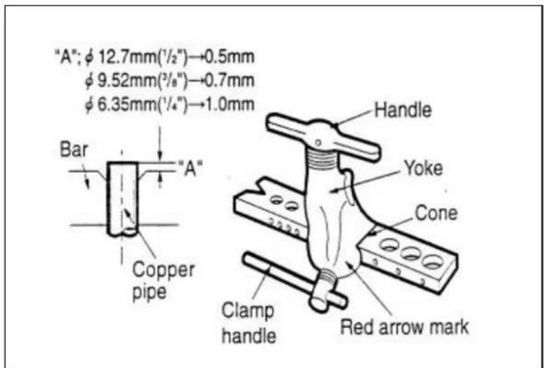
Fit the copper pipe end into the bar of flare tool about 0\~0.5mm higher.
Flare the pipe ends.
4) Tape the flaring portion to protect it from the dust or damages.
- Indoor unit installation
Hook the indoor unit onto the upper portion of installation plate.(Engage the two hooks of the rear top of the indoor unit with the upper edge of the installation plate.)
Ensure the hooks are properly seated on the installation plate by moving it in left and right.

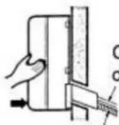
Connecting cable
Drain hose
Press the lower left and right side of the unit against the installation Plate until the hooks engages with their slots(sound click).
- Connecting the piping to the indoor unit
Align the center of the piping and sufficiently tighten flare nut with fingers.
Finally, tighten the flare nut with torque wrench until the wrench clicks.
Wrench tightening the flare nut torque wrench, ensure the direction for tightening follows the arrows on the wrench.
| Pipe Size Torque | |
| Liquid Side(φ6 or 1/4 inch) | 1.8 kg.m |
| Liquid Side (φ10 or 3/8 inch) | 3.5 kg.m |
| Liquid Side(φ12 or 1/2 inch) | 5.5 kg.m |
| Gas Side (φ10 or 3/8 inch) | 3.5 kg.m |
| Gas Side(φ12 or 1/2 inch) | 5.5 kg.m |
| Gas Side(φ16 or 5/8 inch) | 7.5 kg.m |
| Gas Side(φ19 or 3/4 inch) | 10.0 kg.m |
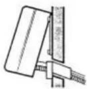
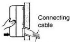
Drain hose
Press the lower left and right side of the unit against the installation Plate until the hooks engages with their slots(sound click).
● Wrap the insulation material around the connecting portion.
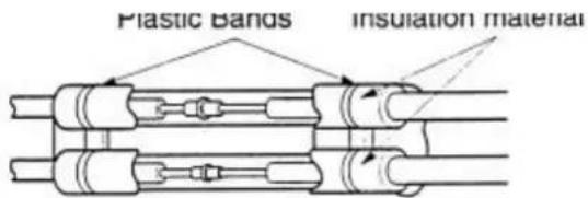
Wrap the insulation material around the connecting portion.
4. CONNECTING PIPINGS AND THE CABLE TO OUTDOOR UNIT
- Connecting the piping to outdoor unit
Align the center of the piping and sufficiently tighten the flare nut with fingers.
Finally, tighten the flare nut with torque wrench until the wrench clicks.
When tightening the flare nut with torque wrench, ensure the direction for tightening follows the arrows on the wrench.
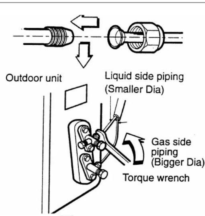
| Pipe Size Torque | |
| Liquid Side(φ6 or 1/4 inch) | 1.8 kg.m |
| Liquid Side (φ10 or 3/8 inch) | 3.5 kg.m |
| Liquid Side(φ12 or 1/2 inch) | 5.5 kg.m |
| Gas Side (φ10 or 3/8 inch) | 3.5 kg.m |
| Gas Side(φ12 or 1/2 inch) | 5.5 kg.m |
| Gas Side(φ16 or 5/8 inch) | 7.5 kg.m |
| Gas Side(φ19 or 3/4 inch) | 10.0 kg.m |
- Connecting the cable to the outdoor unit as shown in OPERATING AND INSTALLATION INSTRUCTIONS MANUAL.
5. CHECKING THE DRAINAGE AND CONNECTING THE CABLE TO INDOOR UNIT
- Checking the drainage
1) Remove the grille from the cabinet
Set the up-and-down air direction louver to open position (horizontally) by finger pressure.
Remove the screw caps and the securing screws.
To remove the grille, pull the lower left and right side of the grille toward you (slightly titled) and lift it straight upward(Two tabs on the top inside edge of the grille are clear of their slots).

2) Check the drainage
Pour glass of water on the evaporator.
Ensure if water flows from drainage hose of indoor unit.
- Form the piping
Wrap the connecting portion of indoor unit with the insulation material and secure it with two plastic bands (for the right piping).
If you may connect an additional drainage hose, the end of the drainage-outlet should keep distance from the ground.(Do not dip it into water, and fix it on the wall to avoid swinging in the wind.)
- In case of the outdoor unit is installed below position of the indoor unit.
Tape the piping, drainage hose and connecting cable from down to up.
Form the piping gathered by taping along the exterior wall and fix it onto the wall by saddle or equivalent.


- In case of the outdoor unit is installed upper position of the indoor unit.
Tape the piping and connecting cable from down to up.
Form the piping gathered by taping along the exterior wall and the trap is required to prevent water from entering into the room.
Fix the piping onto the wall by saddle or equivalent.
- Connecting the cable to the indoor unit as shown in the OPERATING AND INSTALLATION INSTRUCTIONS MANUAL.
6. AIR PURING OF THE PIPINGS AND INDOOR UNIT
● Air purging preparation
Remove the caps from the 2-way and 3-way valves.
Remove the service-port cap from the 3-way valve.
To open the valve, turn the valve spindle of 2-way valve counter-clockwise approximate 90° and hold it there for 5 seconds, then close it.
Caution: Do not leak the gas in the air during air purging.

- Leakage checking
Check a gas-leakage of the connection portion of the piping.
If there is no leakage found, open 2-way again, turn the valve spindle counter-clockwise until it stops.
If there is leakage found, re-tighten the connecting portion with wrench. If the leakage persists, locate a leakage and repair it until leakage ceases.

flowchart
graph TD
    A["No leakage found"] --> B["Open 2-way valve again, turn the valve spindle counter-clockwise until it stops"]
    C["Leakage found"] --> D["Re-tighten the connecting portion with wrench"]
    B --> E["Purge the air, push the pin on the service port of the 3-way valve for three seconds with a hexagonal wrench, wait for one minute. Repeat the operation for three times."]
    D --> F["Leakage ceases"]
    D --> G["Leakage persists"]
    F --> H["Locate a repair leak"]
    G --> H
Air purging
To purge the air, push the pin on the service port of 3-way valve for three seconds with a hexagonal wrench, wait for one minute.
Repeat the operation three times.
- Set the both 2-way and 3-way valves to open position with the hexagonal wrench for the unit operation.
- Checking a gas leakage for the left piping
connect the manifold gauge to the service port of 3-way valve. Measure the pressure.
Keep it for 5\~10 minutes. Ensure if the pressure indicated on the gauge is as same as that of measured at the first time.
● Follow the result of right side piping. - The additional gas for air purging has been charged in the outdoor unit. However, if the flare connections have not been done correctly and gas leaks a gas cylinder and the charge set will be needed.

flowchart
graph TD
    A["Indoor unit"] --> B["Liquid side"]
    B --> C["Open"]
    C --> D["Outdoor unit"]
    D --> E["Close"]
    E --> F["OPEN"]
    E --> G["CLOSE"]
    H["Gas side"] --> I["Open"]
    J["Open"] --> K["Close"]
    L["Open"] --> M["CLOSE"]
CHAPTER 8: 2-WAY, 3-WAY VALVE
| 2-way Valve(Liquid Side) | 3-way Valve(Gas Side) | ||
| Works | Spindle position | Spindle position | Service port |
| Shipping | Closed(with valve cap) | Closed(with valve cap) | Closed(with cap) |
| Air purging(Installation) | Open(counter-clockwise) | Closed(clockwise) | Open(push-pin) |
| Operation | Open(with valve cap) | Open(with valve cap) | Closed(with cap) |
| Pumping down(Transferring) | Closed(clockwise) | Open(counter-clockwise) | Open(connected manifold gauge) |
| Evacuation(Servicing) | Open Open | Open(with charging cylinder) | |
| Gas charging(Servicing) | Open Open | Open(with charging cylinder) | |
| Pressure check(Servicing) | Open Open | Open(with charging cylinder) | |
| Gas releasing(Servicing) | Open Open | Open(with charging cylinder) | |


1. AIR PURGING (INSTALLATION)
- Required tools: hexagonal wrench, adjustable wrench, torque wrenches, wrench to hold the joints, and gas leak detector.
- The additional gas for air purging has been charged in the outdoor unit. However, if the flare connections have not been done correctly and gas leaks, a gas cylinder and the charge set will be needed.
- The air in the indoor unit and in the piping must be purged. If air remains in the refrigerant pipes, it will affect the compressor, reduce the cooling and heating capacity, and could lead to a malfunction.

flowchart
graph TD
    A["Indoor unit"] --> B["Liquid side"]
    C["Gas side"] --> D["Open 2-way valve"]
    D --> E["Outdoor unit"]
    B --> F["3-way valve"]
    D --> G["Close"]
- Be sure to use a torque wrench to tighten the service port cap (after using the service port), so that it prevents the gas leakage from the refrigeration cycle.
● Caution: Do not leak the gas in the air during air purging.
● Air purging procedure
Recheck the piping connections.
Open the valve spindle of the 2-way valve counter-clockwise proximately 90°, wait 10 seconds, and then set it to closed position. Be sure to use a hexagonal wrench to operate the spindle.
Check the flare connections for refrigerant gas leakage.
Purge the air from the system. Set the 2-way valve to the open position and remove the cap from the 3-way valve's service port. Using the hexagonal wrench to press the valve core pin, discharge for three seconds and then wait for one minute. Repeat this three times.
Use torque wrench to tighten the service port cap to a torque of 1.8kg.cm.
Set the 3-way valve to the back seat.
Mount the valve caps to the 2-way and 3-way valves.
Check for gas leakage. At this time, especially check for gas leakage from the 2-way and 3-way valve's caps, and from the service port cap.
● Caution: If gas leakage is discovered, take the following measures.
If the gas leakage stops when the piping connections are tightened further, continue working.
If the gas leakage does not stop when the piping connections are tightened, repair the location of the leakage, discharge all of the gas through the service port, and then recharge with the specified amount of gas from a gas cylinder.
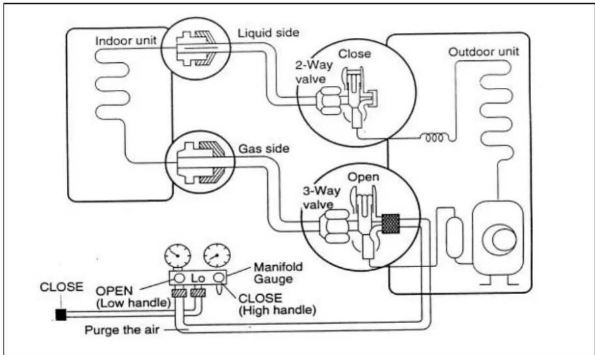
2. PUMPING DOWN (BEFORE RE-INSTALLATION)
flowchart
graph TD
    A["Indoor unit"] --> B["Liquid side"]
    B --> C["2-Way valve"]
    C --> D["Open"]
    D --> E["3-Way valve"]
    E --> F["Outdoor unit"]
    G["Gas side"] --> H["LO"]
    I["Purge the air"] --> J["Manifold Gauge"]
    K["CLOSE"] --> L["OPEN (Low handle)"]
    M["CLOSE"] --> N["CLOSE (High handle)"]
- Confirm that both the 2-way and 3-way valves are set to the open position.
Remove the valve caps and confirm that the valve spindles are in the open position.
Be sure to use a hexagonal wrench to operate the valve spindle. - Operate the unit for 10\~15 minutes.
- Stop operation and wait for 3 minutes, then connect the charge set to the service port of the3-way valve.
Connect the charge hose with the push pin to the service port.
● Air purging of the charge hose
Open the low-pressure valve on the charge set slightly to purge air from the charge hose. - Set the 2-way valve to the closed position.
- Operate the air conditioner at the cooling cycle and stop it when the gauge indicates 1kg/cm^2 .g.
- Immediately set the 3-way valve to the closed position.
Do this quickly so that the gauge ends up indicating 3 to 5kg/cm^2 .g. - Disconnect the charge set, and amount the 2-way and 3-way valve's caps and the service port cap.
Use torque wrench to tighten the service port cap to a torque of 1.8 kg.m.
Be sure to check for gas leakage.
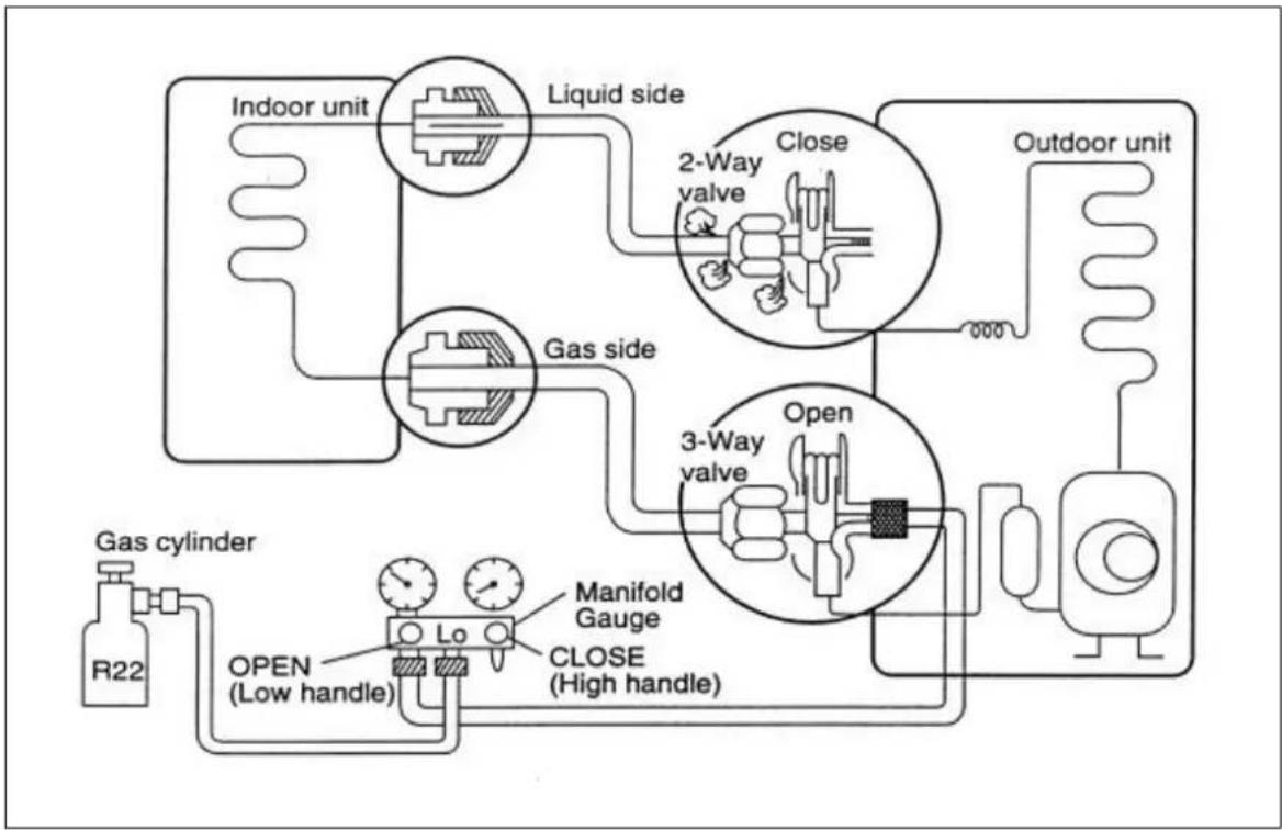
3. RE-AIR PURGING FOR RE-INSTALLATION
- Confirm that both the 2-way valve and the 3-way valve are set to the closed position.
- Connect the charge set and a gas cylinder to the service port of the 3-way valve.
Leave the valve on the gas cylinder closed.
Air purging
Open the valves on the gas cylinder and the charge set. Purge the air by loosening the flare nut on the 2-way valve approximately 45° for 3 seconds, then
closing it for 1 minute. Repeat 3 times.
After purging the air, use a torque wrench to tighten the flare nut on the 2-way valve.
flowchart
graph TD
    A["Indoor unit"] --> B["Liquid side"]
    B --> C["2-Way valve"]
    C --> D["Close"]
    D --> E["Outdoor unit"]
    F["Gas cylinder R22"] --> G["OPEN (Low handle)"]
    G --> H["Manifold Gauge"]
    H --> I["CLOSE (High handle)"]
    I --> J["Open 3-Way valve"]
    J --> K["Open"]
- Check the flare connections for gas leakage.
-
Disconnect the charge set and the gas cylinder, and set the 2-way and 3-way valves to the open position.
Be sure to use a hexagonal wrench to operate the valve spindles.
● Mount the valve caps and the service port cap.
Use torque wrench to tighten the service port cap to a torque of 1.8kg.m.
Be sure to check for gas leakage.
● Caution: Do not leak the gas in the air during air purging. -
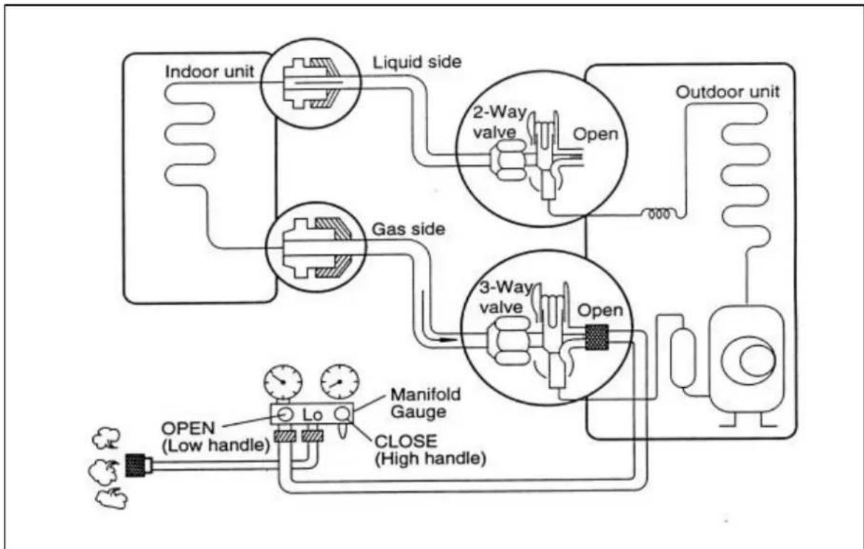
BALANCE REFRIGERANT OF THE 2-WAY, 3-WAY VALVES (GAS LEAKED)
- Confirm that both the 2-way and 3-way valves are set to the back seat.
- Connect the charge set to the 3-way valve's service port.
Leave the valve on the charge set closed.
Connect the charge hose with the push pin to the service port.
flowchart
graph TD
    A["Indoor unit"] --> B["Liquid side"]
    B --> C["2-Way valve Open"]
    C --> D["Outdoor unit"]
    E["Gas side"] --> F["3-Way valve Open"]
    F --> G["Open"]
    H["Manifold Gauge"] --> I["OPEN (Low handle)"]
    I --> J["LO"]
    J --> K["CLOSE (High handle)"]
    style A fill:#f9f,stroke:#333
    style B fill:#ccf,stroke:#333
    style C fill:#cfc,stroke:#333
    style D fill:#fcc,stroke:#333
    style E fill:#cff,stroke:#333
    style F fill:#ffc,stroke:#333
    style G fill:#fcc,stroke:#333
    style H fill:#ffc,stroke:#333
    style I fill:#cfc,stroke:#333
    style J fill:#fcc,stroke:#333
    style K fill:#cfc,stroke:#333
- Open the valve (Low side) on the charge set and discharged the refrigerant until the gauge indicates 0kg/cm^2 .
If there is no air in the refrigerant cycle (the pressure when the air conditioner is not running is higher than 1 kg/cm^2 · g ), discharge the refrigerant until the gauge indicates 0.5 to 1 kg/cm^2 · g . If this is the case, it will not be necessary to apply an evacuation.
Discharge the refrigerant gradually. If it is discharged too suddenly, the refrigeration oil will also be discharged.
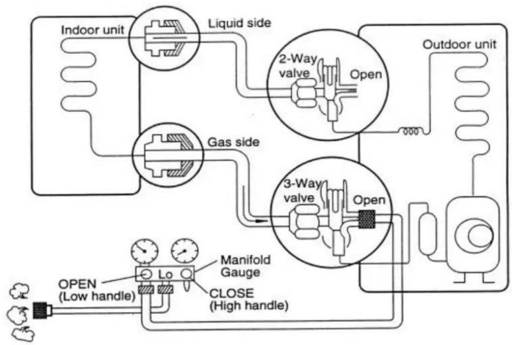
5. EVACUATION (ALL AMOUNT OF REFRIGERANT LEAKED)
-
Connect the vacuum pump to the charge set's center hose.
● Evacuating for approximately one hour.
Confirm that the gauge needle has moved toward -76cmHg (vacuum of 4 mmHg or less) -
Close the valve (Low side) on the charge set, turn off the vacuum pump, and confirm that the gauge needle does not move (approximately 5 minutes after turning off the vacuum pump).
- Disconnect the charge hose from the vacuum pump.
If the vacuum pump oil becomes dirty or depleted, replenish as needed.
flowchart
graph TD
    A["Indoor unit"] --> B["Liquid side"]
    B --> C["2-Way valve Open"]
    C --> D["Outdoor unit"]
    E["Gas side"] --> F["3-Way valve Open"]
    F --> G["Manifold Gauge Close (High handle)"]
    G --> H["OPEN (Low handle)"]
    style A fill:#f9f,stroke:#333
    style B fill:#ccf,stroke:#333
    style C fill:#cfc,stroke:#333
    style D fill:#fcc,stroke:#333
    style E fill:#cff,stroke:#333
    style F fill:#ffc,stroke:#333
    style G fill:#cfc,stroke:#333
    style H fill:#fcc,stroke:#333
6. GAS CHARGING (AFTER EVACUATION)
- Connect the charge hose to the charging cylinder.
Connect the charge hose which you disconnected from the vacuum pump to the valve at the bottom of the cylinder.
If you are using a gas cylinder, also use a scale and level the cylinder so that the system can be charged with liquid.
● Purge the air from the charge hose.
Open the valve at the bottom of the cylinder and press the check valve on the charge set to purge the air.(Be careful of the liquid refrigerant).The procedure is the same if using a gas cylinder. - Open the valve (Low side on the charge set) and charge the system with liquid
refrigerant.
If the system can not be charged with the specified amount of refrigerant, it can be charged with a little at a time (approximately 150g each time) while operating the air conditioner in the cooling cycle. However, one time is not sufficient, wait approximately 1 minute and then repeat the procedure (pumping down pin).
This is different from previous procedures. Because you are charging with liquid refrigerant from the gas side, absolutely do not attempt to charge with larger amounts of liquid refrigerant while operating the air conditioner.
- Immediately disconnect the charge hose from the 3-way valve's service port.
Stopping partway will allow the gas to be discharged.
If the system has been charged with liquid refrigerant while operating the air conditioner before disconnecting the hose.
● Mount the valve caps and service port cap.
Use torque wrench to tighten the service port cap to a torque of 1.8kg.m.
Be sure to check for gas leakage.

flowchart
graph TD
    A["Indoor unit"] --> B["Liquid side"]
    B --> C["2-Way valve Open"]
    C --> D["Outdoor unit"]
    E["Gas side"] --> F["3-Way valve Open"]
    F --> G["Vacuum pump"]
    G --> H["OPEN (Low handle)"]
    H --> I["Lo"]
    I --> J["Manifold Gauge CLOSE (High handle)"]
    J --> K["Open"]
CHAPTER 9: TROUBLESHOOTING
- In order to diagnose malfunctions, make sure that there is no electrical problems before inspecting the refrigeration cycle. Such problems include insufficient thermal insulation, problem with the power supply, malfunction of a compressor and indoor or outdoor fan motor.
- The normal indoor outlet air temperature and pressure of the refrigeration cycle depends upon various conditions. The standard values for them are shown in the following table.
Normal Pressure and Outlet Air Temperature
| Gas Pressure | MPa(kg/cm2.g) | Outlet Air Temperature |
| Cooling Mode | 0.4~0.6(4~6) | 12~16 |
*Condition: Indoor fan speed: High ; Outdoor DB temperature:35
- Checking procedure
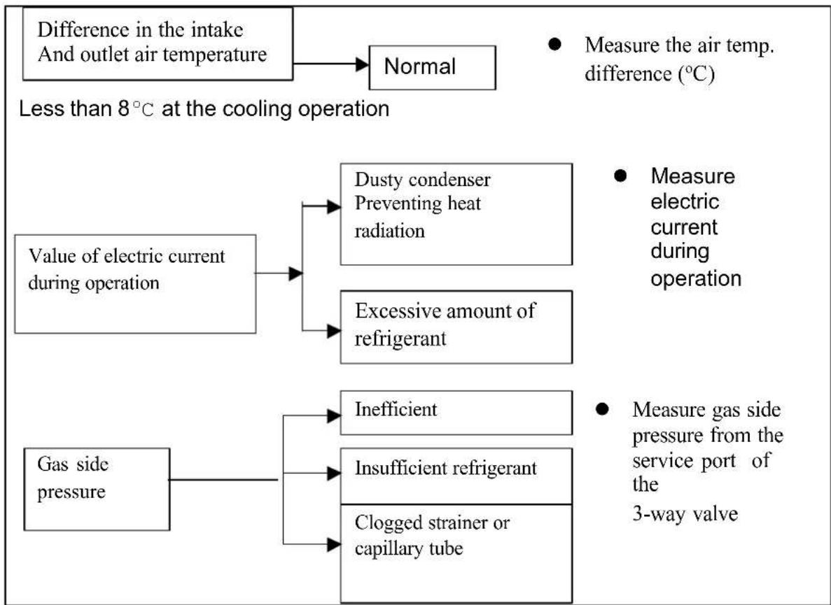
flowchart
graph TD
    A["Difference in the intake And outlet air temperature"] --> B["Normal"]
    C["Less than 8°C at the cooling operation"] --> D["Value of electric current during operation"]
    D --> E["Dusty condenser Preventing heat radiation"]
    D --> F["Excessive amount of refrigerant"]
    G["Gas side pressure"] --> H["Inefficient"]
    G --> I["Insufficient refrigerant"]
    G --> J["Clogged strainer or capillary tube"]
    K["Measure the air temp. difference (°C)"] --> L["Measure electric current during operation"]
    M["Measure gas side pressure from the service port of the 3-way valve"] --> N["●"]
2. RELATION BETWEEN THE CONDITION OF THE AIR CONDITIONER AND PRESSURE AND ELECTRIC CURRENT IN COOLING OPERATION
- Carry out the measurements of pressure, electric current and temperature fifteen minutes after an operation is started.
| Condition of the air conditioner | Lower pressure | High pressure | Electric current during operation |
| Insufficient refrigerant (gas leakage) | Decreased | Decreased | Decreased |
| Clogged capillary tube or strainer | Decreased | Decreased | Decreased |
| Short circuit in the indoor unit | Decreased | Decreased | Decreased |
| Heat radiation deficiency of the outdoor unit | Increased | Increased | Increased |
| Inefficient compression | Increased | Decreased | Decreased |
- DIAGNOSIS METHODS OF A MALFUNCTION OF A COMPRESSOR
| Nature of fault | Symptom |
| Inefficient compressing of a compressor | Electric current during operation becomes approximately 20% lower than the normal value. The discharge tube of the compressor becomes abnormally hot (normally 70 to 90) The difference between high pressure and low pressure becomes almost zero. |
| Locked compressor | Electric current reaches a high level abnormally, and the value exceeds the limit of an ammeter . In some cases, a breaker turns OFF. The compressor has a humming sound. |
- TROUBLE SUSPENSION TABLE
| SYMPTON | PROBABLE CAUSE | CORRECTIVE ACTION |
| The RUN indicator (green)does not light up | The power source voltage is lower than 198V | Repair the power supply |
| No voltage | Repair general wiring | |
| Correct voltage | Replace control P.C.B or display P.C.B | |
| The remote controller batteries are used up | Reload new batteries | |
| The indoor fan does not function correctly | No voltage between indoor fan motor terminals | Replace the control P.C.B |
| Indoor fan motor is broken Replace indoor fan motor | ||
| The outdoor fan does not function correctly | No voltage between outdoor fan motor terminals on the indoor power P.C.B | Replace the control P.C.B |
| No voltage between outdoor fan motor terminals on the outdoor unit | Check and repair electrical wiring between indoor and outdoor units | |
| Outdoor fan is blocked Remove obstructions | ||
| Outdoor fan motor is broken Replace outdoor fan motor | ||
| Outdoor fan motor capacitor is broken | Replace capacitor | |
| The compressor does not start up | No voltage between compressor terminals on the indoor unit | Repair control P.C.B |
| Low voltage between compressor terminals on the indoor unit | Repair control P.C.B | |
| No voltage between compressor terminals on the outdoor unit | Repair electrical wiring between indoor and outdoor units | |
| The running capacitor is broken | Replace running capacitor | |
| OLP of compressor trips | Wait for one hour or so | |
| Compressor winding shorted or broken | Replace compressor | |
| The refrigeration system does not function correctly | Check for leakage or restriction with ammeter, pressure gauge or surface thermometer | Repair refrigeration system and charge refrigerant if necessary |
| No cooling or heating, only indoor fan operates | something wrong with power P.C.B | Replace control P.C.B |
| Outdoor fan motor faulty or other fault caused compressor OLP trips | Remove obstruction or other fault | |
| No cooling or heating, indoor and outdoor fan operate | Compressor OLP trips because of low voltage, high temperature,R22 leakage, little outdoor air circulation and etc | Check the problems and try again one hour later |
| Running capacitor faulty Replace running capacitor | ||
| Compressor is broken Replace compressor | ||
| Water accumulates and overflows from indoor unit | Drainage hose or port of drainage pan clogged | Remove clogged dirt |
| The air conditioner does not function at all with remote controller or AUX switch button on the indoor unit | Power supply failure Repair power supply | |
| The secondary voltage of transformer is approximately 17VAC | Replace control P.C.B | |
| The secondary voltage of transformer is not approximately 17VAC | Replace transformer | |
5. Checking procedure of control circuit
Note: Do not check indoor and outdoor units at the same time. Be sure to check them one by one.

flowchart
graph TD
    A["The machine does not function at all with remote controller and EMERGENCY button on the indoor unit."] --> B{Correct power supply between "L" and "N" of terminal board?}
    B -->|Yes| C["Measure the secondary voltage of transformer"]
    B -->|No| D["None of the three LEDs is ON"]
    C --> E{Is the measured value approx. 17.0 V AC?}
    E -->|Yes| F["Replace the control P.C.B. with a new one"]
    E -->|No| G{Is the connected cord correctly connected?}
    G -->|Yes| H["Correct the connecting cord correctly"]
    G -->|No| I["Use a tester to measure the voltage between "L" and "N" of terminal board on the outdoor unit"]
    H --> J{Is the fuse down?}
    J -->|Yes| K["Replace the transformer with a new one"]
    J -->|No| L["Replace the fuse and varister with new ones"]
    K --> M["Check the electric circuit on the outdoor unit"]

flowchart
graph TD
    A["The machine does not function with the remote controller."] --> B["Push the ON/OFF button on the wireless remote controller."]
    B --> C{Is transmitting signal of the remote controller active?}
    C -->|YES| D{Does beep sound from the indoor unit?}
    C -->|NO| E{Are batteries of remote controller proper?}
    E -->|YES| F["Replace the wireless remote controller."]
    E -->|NO| G["Replace the batteries with new ones."]
    F --> H{Is indicator lamp of indoor unit proper?}
    H -->|YES| I["Indoor unit is normal. Inspect the outdoor Unit or refer to trouble Suspension Table."]
    H -->|NO| J{Is timer lamp of indoor unit flashing?}
    J -->|YES| K["Refer to Trouble Suspension Table."]
    J -->|NO| L["Replace the control P.C.B. assembly"]
    I --> M["Using a tester, measure the voltage of the receiver on display P.C.B.assembly."]
    L --> N["Push the ON/OFF button on the remote controller."]
    N --> O{When the signal is received, does the voltage change?}
    O -->|YES| P["Replace the control P.C.B. assembly with a new one"]
    O -->|NO| Q["Replace the display P.C.B. assembly with a new one."]

flowchart
graph TD
    A["The room is not cooled at all or not cooled enough in cooling operation.<br>The room is not heated at all or not heated enough in heating operation.<br>The compressor does not operate."] --> B["Push the buttons EMERGENCY on the indoor unit."]
    B --> C["Refer to Trouble Suspension Table"]
    C --> D["Measure the resistances of room temperature and indoor pipe temperature thermisters."]
    D --> E["Some of the three indicator LEDs are lit."]
    E --> F["Measure the secondary voltage of transformer."]
    F --> G{Is the measured value approximately 17.0 V AC?}
    G -->|NO| H{Is the fuse breakdown?}
    G -->|YES| I["Replace the control P.C.B. with a new one."]
    H -->|NO| J["Replace the transformer with a new one."]
    H -->|YES| K["Replace the fuse and varister with a new one."]
CHAPTER 10: EXPLODED DRAWINGS
- Exploded view of indoor unit for model: AC-S7CK, AC-7SHK

- Exploded view of outdoor unit for model: AC-S7CK

- Exploded view of outdoor unit for model: AC-S7HK

CHAPTER 11: PART LIST
- Part List of Indoor Unit for AC-S7CK
| No. | DESCRIPTION | Part No. | Q'ty |
| 1 | Installation Plate | 1101297 | 1 |
| 2 | Chassis | 1002110 | 1 |
| 3 | Indoor Fan | 1402283 | 1 |
| 4 | Bearing | 120268 | 1 |
| 5 | Evaporator Assembly | 8130118 | 1 |
| 6 | Cabinet | 2107261 | 1 |
| 7 | Air Filter | 1306145 | 2 |
| 8 | Front Cover | 8100636 | 1 |
| 9 | Safety Cover | 2109232 | 1 |
| 10 | Bearing Support | 100251 | 1 |
| 11 | Left Louver Link | 1201291 | 1 |
| 12 | Vertical Deflector A | 1201288 | 2 |
| 13 | Pipe Assembly (AC-S7/10CK) | 81303151 | 1 |
| 13a | Pipe Assembly (AC-S13CK) | 81303174 | 1 |
| 14 | Draining Pan | 210691 | 1 |
| 15 | Motor Fixing Ring | 1203179 | 1 |
| 16 | Display PCB | 8140921 | 1 |
| 17 | Power Supply Cord Clamp2 | 110963 | 1 |
| Power Supply Cord Clamp1 | 1109147 | 1 | |
| 18 | Terminal Board 3PS | 150265 | 1 |
| 19 | Terminal Fixer | 1109245 | 1 |
| 20 | Control PCB (AC-S7/10CK) | 8140943 | 1 |
| 20a | Control PCB (AC-S13CK) | 8140928 | |
| 21 | Indoor Fan Motor | 1402153 | 1 |
| 22 | Transformer | 814051 | 1 |
| 23 | Electric Box | 1005213 | 1 |
| 24 | Power Supply Cord | 1501185 | 1 |
| 25 | Power Supply Cord Clamp | 1203185 | 1 |
| 26 | Terminal Board 3PU | 150264 | 1 |
| 27 | Power Supply PCB (AC-S7/10CK) | 8140944 | 1 |
| 27a | Power Supply PCB (AC-S13CK) | 8140926 | 1 |
| 28 | Water Preventive Plate | 1203393 | 1 |
| 29 | Drain Hose | 210995 | 1 |
| 30 | Support | 1201292 | 1 |
| 31 | Upper Louver Link | 1201290 | 2 |
| 32 | Vertical Deflector B | 1201289 | 10 |
| 33 | Louver Motor | 1402136 | 1 |
| 34 | Right Louver Link | 1201293 | 1 |
| 35 | Horizontal Louver | 1201381 | 1 |
| 36 | Remote Controller | 1401394 | 1 |
| 37 | Thermistor | 1411366 | 1 |
- Part List of Outdoor Unit for AC-S7CK
| No. | DESCRIPTION | Part No. | Q'ty |
| 1 | Top Cover | 810136 | 1 |
| 2 | Condenser | 8130226 | 1 |
| 3 | Motor Stay Bracket | 811022 | 1 |
| 4 | Outdoor Fan Motor | 1402371 | 1 |
| 5 | Outdoor Fan | 1402181 | 1 |
| 6 | Cabinet | 810065 | 1 |
| 7 | Fan Guard | 821072 | 1 |
| 8 | Back Lattice Plate | ||
| 9 | Electrical Assembly | 8140117 | 1 |
| 10 | Electrical Assembly Plate | 821022 | 1 |
| 11 | Electrical Assembly Seal | 1 | |
| 12 | Power Supply Cord Clamp 1 | 110963 | 1 |
| 13 | Power Supply Cord Clamp 2 | 1109147 | 1 |
| 14 | Terminal Board 2U | 150217(A) | 2 |
| 15 | Terminal Board 3PU | 150264 | 1 |
| 16 | Fan motor Capacitor | 141111 | 1 |
| 17 | Compressor Capacitor | 14111418 | 1 |
| 18 | Power Supply Cord | 1501545 | 1 |
| 19 | Capacitor Fixing Ring | 812031 | 1 |
| 20 | Bulkhead | 811094 | 1 |
| 21 | Chassis | 810027 | 1 |
| 22 | Compressor | 1304297 | 1 |
| 23 | Right Side Plate | 810038 | 1 |
| 24 | Valve Fixing Plate | 811092 | 1 |
| 25 | Terminal Cover | 821021 | 1 |
| 26 | 3 Way Valve Assembly | 8130917 | 1 |
| 27 | 2 Way Valve Assembly | 8130916 | 1 |
| 28 | Suction Pipe | 81303149 | 1 |
| 29 | Discharging Pipe | 81303150 | 1 |
| 30 | Capillary Tube Assembly | 81303143 | 1 |
- Part List of Indoor Unit for AC-S7HK
| No. | DESCRIPTION | Part No. | Q'ty |
| 1 | Installation Plate | 1101297 | 1 |
| 2 | Chassis | 1002110 | 1 |
| 3 | Indoor Fan | 1402283 | 1 |
| 4 | Bearing | 120268 | 1 |
| 5 | Evaporator Assembly | 8130118 | 1 |
| 6 | Cabinet | 2107261 | 1 |
| 7 | Air Filter | 1306145 | 2 |
| 8 | Front Cover | 8100636 | 1 |
| 9 | Safety Cover | 2109232 | 1 |
| 10 | Bearing Support | 100251 | 1 |
| 11 | Left Louver Link | 1201291 | 1 |
| 12 | Vertical Deflector A | 1201288 | 2 |
| 13 | Pipe Assembly | 81303151 | 1 |
| 13a | Pipe Assembly | 81303174 | 1 |
| 14 | Draining Pan | 210691 | 1 |
| 15 | Motor Fixing Ring | 1203179 | 1 |
| 16 | Display PCB | 8140921 | 1 |
| 17 | Power Supply Cord Clamp2 | 110963 | 1 |
| Power Supply Cord Clamp1 | 1109147 | 1 | |
| 18 | Terminal Board 5PU | 150262 | 1 |
| 19 | Terminal Fixer | 1109245 | 1 |
| 20 | Control PCB (AC-S7/10HK) | 8140943 | 1 |
| 20a | Control PCB (AC-S13HK) | 8140976 | |
| 21 | Indoor Fan Motor | 1402153 | 1 |
| 22 | Transformer | 814051 | 1 |
| 23 | Electric Box | 1005213 | 1 |
| 24 | Power Supply Cord | 1501185 | 1 |
| 25 | Power Supply Cord Clamp | 1203185 | 1 |
| 26 | Terminal Board 3PS | 150265 | 1 |
| 27 | Power Supply PCB (AC-S7/10HK) | 8140942 | 1 |
| 27a | Power Supply PCB (AC-S13HK) | 8140975 | 1 |
| 28 | Water Preventive Plate | 1203393 | 1 |
| 29 | Drain Hose | 210995 | 1 |
| 30 | Support | 1201292 | 1 |
| 31 | Upper Louver Link | 1201290 | 2 |
| 32 | Vertical Deflector B | 1201289 | 10 |
| 33 | Louver Motor | 1402136 | 1 |
| 34 | Right Louver Link | 1201293 | 1 |
| 35 | Horizontal Louver | 1201381 | 1 |
| 36 | Remote Controller | 1401394 | 1 |
| 37 | Thermistor | 1411366 | 1 |
- Part List of Outdoor Unit for AC-S7HK
| No. | DESCRIPTION | Part No. | Q'ty |
| 1 | Top Cover | 810136 | 1 |
| 2 | Condenser | 8130226 | 1 |
| 3 | Motor Stay Bracket | 811022 | 1 |
| 4 | Outdoor Fan Motor | 1402371 | 1 |
| 5 | Outdoor Fan | 1402181 | 1 |
| 6 | Cabinet | 810065 | 1 |
| 7 | Fan Guard | 821072 | 1 |
| 8 | Back Lattice Plate | ||
| 9 | Electrical Assembly | 8140117 | 1 |
| 10 | Electrical Assembly Plate | 821022 | 1 |
| 11 | Electrical Assembly Seal | 1 | |
| 12 | Power Supply Cord Clamp 1 | 110963 | 1 |
| 13 | Power Supply Cord Clamp 2 | 1109147 | 1 |
| 14 | Terminal Board 2U | 150217(A) | 2 |
| 15 | Terminal Board 3PU | 150264 | 1 |
| 16 | Fan motor Capacitor | 141111 | 1 |
| 17 | Compressor Capacitor | 14111418 | 1 |
| 18 | Power Supply Cord | 1501545 | 1 |
| 19 | Capacitor Fixing Ring | 812031 | 1 |
| 20 | Bulkhead | 811094 | 1 |
| 21 | Chassis | 810027 | 1 |
| 22 | Compressor | 1304297 | 1 |
| 23 | Right Side Plate | 810038 | 1 |
| 24 | Valve Fixing Plate | 811092 | 1 |
| 25 | Terminal Cover | 821021 | 1 |
| 26 | 3 Way Valve Assembly | 8130917 | 1 |
| 27 | 2 Way Valve Assembly | 8130916 | 1 |
| 28 | 4 Way Valve | 141187 | 1 |
| 28a | 4 Way Valve Coil | 1411458 | 1 |
| 29 | Capillary Tube Assembly | 81303135 | 1 |
APPENDIX A
| Description | Singapore / AKIRA | |||||||||
| Akira Model No. | AC-S7CK | AC-S7IIK | AC-S10CK | AC-S10IIK | AC-S13CK | AC-S13IIK | AC-S19CK | AC-S19IIK | AC-S24CK | AC-S24IIK |
| Type (Cool only / Heat Pump) | C | C/II | C | C/II | C | C/II | C | C/II | C | C/II |
| Cooling Capacity (Btu) | 7000 | 10000 | 13000 | 19000 | 24000 | |||||
| Heating Capacity (Btu) | N/V | 7000 | N/V | 10000 | N/V | 13000 | N/V | 19000 | N/V | 24000 |
| Power Input (W) | 730 | 800 | 1425 | 1590 | 2700 | |||||
| Current (A) | 3.4 | 3.7 | 6.2 | 7.5 | 12.5 | |||||
| EER (Btu/Hw) | 9.1 | 9.0 | 8.6 | 10 | 8.89 | |||||
| Indoor Noise (H/L) | 35/30Db | 35/30Db | 38/33Db | 43/37Db | 40 | |||||
| Circulation Air Flow(m3/h) | 420 | 420 | 480 | 750 | 780 | |||||
| Indoor Unit (WxDxH)mm | 770x179x240 | 897x179x297 | 1025x203x3139 | |||||||
| Indoor Unit Carton (WxDxH)mm | 830x240x310 | 1010x300x410 | 1130x300x395 | |||||||
| Outdoor Unit (WxDxH)mm | 755x252x530 | 800x268x637 | 832x380x702 | |||||||
| Outdoor Unit Carton (WxDxH)mm | 890x350x580 | 975x400x755 | 970x765x410 | |||||||
| Indoor N/G Wt (kg) | 8.0/10 | 8.0/10 | 8.0/10 | 8.0/10 | 8.0/10 | 8.0/10 | 11.0/14 | 11.0/14 | 13.2/21 | 13.2/21 |
| Outdoor N/G Wt (kg) | 26.0/31 | 30.0/35 | 28.0/33 | 30.0/35 | 28.0/33 | 34.0/39 | 50.0/58 | 53.0/61 | 55.0/63 | 56.0/64 |
| Compressor Brand | Mitsubishi | Mitsubishi | Toshiba | LG | LG | Toshiba | Hitachi | |||
| Gas Pipe Diameter | 3/8" (or 10mm) | 1/2" (or 12mm) | 5/8" (or 16mm) | |||||||
| Liquid Pipe Diameter | 1/4" (or 6mm) | 1/4" (or 6mm) | 3/8" (or 10mm) | |||||||
| Piping (m) | 5 | |||||||||
| 40HQ CTN Loading | 245 sets | 152 sets | 123 sets | |||||||
| Indoor Unit Picture |  |  |  | |||||||




- CHAPTER 2: SPECIFICATIONS
- TEMPERATURE RANGE FOR T3 CLIMATE AIR CONDITIONER
- REFRIGERANT PIPING
- CHAPTER 4: REMOTE CONTROLLER
- ON/OFF BUTTON
- MODE BUTTON
- FAN SPEED BUTTON
- 4.TEMPERATURE SETTING BUTTON
- SWING BUTTON
- SMART BUTTON
- TIMER SET/CANCEL BUTTON
- SLEEP BUTTON
- SUPER BUTTON
- Indication symbols on LCD:
- Cooling only appliance
- Heat pump
- CHAPTER 6: OPERATION DETAILS
- SAFETY CONTROL
- ● 3 minutes delay for compressor
- ● 59 seconds delay for reversing valve
- • Over-current control
- - Freeze preventive control
- ● Overheating protection system
- AIR FLOW DIRECTION CONTROL
- DRY MODE OPERATION
- SMART MODE OPERATION
- AUTO FAN SPEED
- INDOOR FAN SPEED CONTROL
- EMERGENT START
- AUTORESTART FUNCTION
- DEFROST
- Preventive System.
- SLEEP MODE OPERATION
- CHAPTER 7: INSTALLATION
- 2) Remove burrs
- 3) Flaring the pipes
- CONNECTING PIPINGS AND THE CABLE TO OUTDOOR UNIT
- CHECKING THE DRAINAGE AND CONNECTING THE CABLE TO INDOOR UNIT
- AIR PURING OF THE PIPINGS AND INDOOR UNIT
- AIR PURGING (INSTALLATION)
- PUMPING DOWN (BEFORE RE-INSTALLATION)
- RE-AIR PURGING FOR RE-INSTALLATION
- EVACUATION (ALL AMOUNT OF REFRIGERANT LEAKED)
- GAS CHARGING (AFTER EVACUATION)
- CHAPTER 9: TROUBLESHOOTING
- RELATION BETWEEN THE CONDITION OF THE AIR CONDITIONER AND PRESSURE AND ELECTRIC CURRENT IN COOLING OPERATION
- Checking procedure of control circuit
- CHAPTER 10: EXPLODED DRAWINGS
- CHAPTER 11: PART LIST
Brand : AKIRA
Model : AC-S7
Category : Air conditioner