
WK227F - Range hood Atag - Free user manual and instructions
Find the device manual for free WK227F Atag in PDF.


| Product type | Wall-mounted extractor hood |
| Brand | Atag |
| Model | WK227F |
| Width | 60 cm |
| Depth | 50 cm |
| Height (min-max) | 65-110 cm |
| Net weight | 12 kg |
| Power supply | 220-240 V ~ 50 Hz |
| Motor power | 200 W |
| Maximum extraction | 620 m³/h |
| Noise level (max) | 65 dB(A) |
| Type of grease filter | Washable aluminium |
| Carbon filter (optional) | Yes, suitable model |
| Lighting | LED, 2 x 2 W |
| Controls | Mechanical sliders |
| Energy class | B |
| Air outlet diameter | 150 mm |
| Material | Stainless steel / glass |
| Cleaning | Grease filter dishwasher safe |
| Safety | Automatic shutdown in case of overheating |
| Spare parts available | Yes, via Atag after-sales service |
| Repairability | Repairability index not communicated |
Frequently Asked Questions - WK227F Atag
User questions about WK227F Atag
0 question about this device. Answer the ones you know or ask your own.
Ask a new question about this device
Download the instructions for your Range hood in PDF format for free! Find your manual WK227F - Atag and take your electronic device back in hand. On this page are published all the documents necessary for the use of your device. WK227F by Atag.
USER MANUAL WK227F Atag
instructions for use / installation instructions
natural_image
Simple line drawing of a rectangular electronic device with two ports and a central connector (no text or symbols)} WK627F/W6.0
} WK227F



natural_image
Pure technical line drawing of a mechanical part without any text, numbers, or symbols
natural_image
Technical line drawing of a mechanical assembly with no visible text or symbols|NL |NL
Toestelbeschrijving
Bedieningspaneel
Zie figuur 1.
A = lichtschakelaar
stand 0: licht uit
stand 1: licht aan
natural_image
Technical line drawing of a mechanical component with two hanging parts and a base, labeled Fig. 7 (no text or symbols on the diagram itself)
natural_image
Pure mechanical diagram showing a lever and shaft assembly without any text, numbers, or symbolsb 2
“1
Nederlands 2 - 7
English 8-13
Français 14 - 19
Deutsch 20 - 25
Italiano 26 - 31
Dansk 32 - 37
ελληνικα ....38 - 43
Introductie
Controls illustrated in fig. 1:
A = light switch
Position O: light off
Position 1: light on
B = motor switch
C = indicator light: indicates motor is in operation
Building-in dimensions
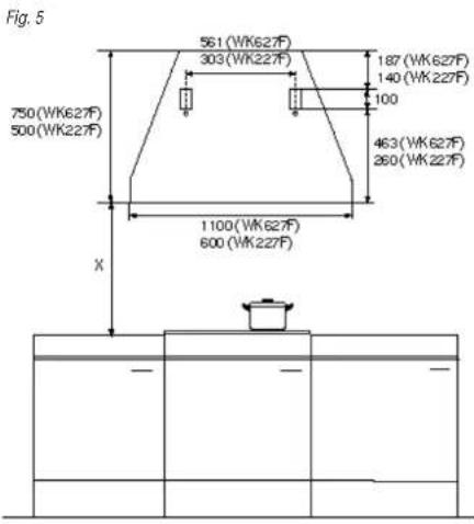
Check the distance between the cooker and the extractor hood (X, see fig. 5). When installed above an electric cooker this distance must be at least 65~cm . When installed above a gas cooker this distance must be at least 75~cm .
9
Introduction
When you have read these instructions for use, you will quickly be aware of all the facilities the appliance can offer you. You can read about safety and how you should look after the appliance. In addition you will find environmental tips and instructions that can help to save energy.
Keep the instructions for use and the installation instructions. Any later user of this appliance could benefit from them.
Enjoy your cooking!
Table of contents
Appliance description 8
Introduction 9
Safety instructions....10
Extraction system....11
Maintenance....11
Changing the light bulbs .....11
Installation 11
Atag's guarantee 12
Disposal of packaging and appliance .....13
Technical specifications....13
1 GE
10
Safety instructions
*The distance between the hob and the lower part of the extractor hood must be at least 65 cm.
*Under no circumstances should the outlet be connected to a duct which is also being used to discharge exhaust gas from appliances fuelled by an energy source other than electricity (central heating systems, thermosiphons, water heaters, etc.).
*When installing the discharge outlet always comply with the regulations in force as issued by the relevant authorities.
*Caution is needed if an extractor hood and another heat source (e.g. gas, oil, coal stoves, etc.) which also requires air are being used together in the same room, since it is possible that the extractor hood may deplete the necessary combustion air and thus create a depression in the room. In order to ensure that the exhaust gas from the heat source is not drawn into the room, the maximum depression permitted in the room is 0.04 mbar. There must also be an air source in the room which constantly feeds the room with a steady flow of fresh air.
*To avoid possible risk of fire always comply with the instructions for use when cleaning anti-grease filters and when removing grease deposits from the appliance.
The following warning applies only in the United Kingdom:
It is possible that the colours of the wires in the mains cable of this appliance may not correspond with the coloured markings identifying the terminals in your plug. If this is the case, proceed as follows:
*The blue wire must be connected to the terminal which is marked with the letter N or coloured black;
*The brown wire must be connected to the terminal which is marked with the letter L or coloured red;
*Neither wire is to be connected to the earth terminal of a three-pin plug.
*When making the electrical connections check that the voltage corresponds with that indicated on the rating plate inside the extractor hood.
*In the event that your appliance is not fitted with a non-separating flexible cable and has no plug, or has no other device to ensure omnipolar disconnection from the electrical main with a contact opening of at least 3 mm, such a separating device must be included in the fixed installation to ensure disconnection from the main.
*Always disconnect this appliance from the main before cleaning or servicing the appliance.
*Never flambée under an extractor hood.
*When frying take special care to prevent oils and fats from catching fire. Oil which has already been used is especially dangerous in this respect. Do not use exposed electric grills.
Extraction system
The cooker hood must be connected in the Discharge mode (fig. 2) cooking vapours and/or odours are immediately discharged outside (via the ceiling and/or a wall) by a discharge duct using the hole positioned on the top of the appliance.
Maintenance
The thorough cleaning and servicing of the appliance ensures correct and long-lasting operation:
*Use lukewarm water and a neutral liquid detergent to clean varnished appliances. Never use abrasive cleaning materials or products (Vim, steel wool, green scouring pads, liquid scouring agents).
*Never use corrosive or abrasive products when cleaning steel copper or brass appliances. It is recommended that specialized products be used in accordance with the instructions issued by the manufacturer.
Anti-grease filters
*Push the filters firmly to the rear (see fig. 3). Allow to fall at the front to remove them.
*The anti-grease filters can be cleaned by hand with neutral detergent. If the filters are cleaned in a dishwasher, some discolouration may occur. The discolouration of the filters is not covered by the guarantee.
Changing the light bulbs
Remove the cover ring by turning it a quarter of a turn (1, see fig. 4). Remove the halogen bulb by pulling it down carefully (2). Insert a new halogen bulb (20 W) and replace the cover ring.
Installation
Before assembling the appliance it is necessary to remove the anti-grease filters.
The following procedures must be carried out before installing the appliance:
* A proper wiring system must be installed.
*If your appliance is to be installed in Discharging mode, the ventilation hole must first be made and a proper pipe obtained to connect the vent to the flange of the extractor hood.
Atag's guarantee
Wall fitting
*Mark the position of the brackets on the wall (fig. 5). Attach the brackets supplied to the wall, so that the appliance can be hooked onto the brackets by the holes specially provided.
*Once the appliance is hooked in place it can be firmly secured to the wall using the safety screws (A, see fig. 6).
*Finally make the electrical connections.
Assembly of the knobs and the handle
*Press the knobs onto the stems (see figure 7).
*Attach the handle to the extractor hood using the enclosed nuts (see figure 8).
The guarantee conditions listed below are only valid in countries with an Atag establishment. In other countries, your supplier or Atag importer can provide you with information about the Atag guarantee-and service conditions.
Scope of the terms of guarantee:
ATAG warrants this appliance for the following guarantee periods:
- 5-year guarantee on parts
- 1-year service guarantee
The guarantee on ATAG kitchen appliances is valid only if the appliance has been installed for household use and is used only for the purposes for which it was designed.
The guarantee period is effective from the date of delivery of the appliance. Evidence of the date of delivery must be provided upon request, for example with a delivery slip or sales receipt.
Parts which malfunction as a result of material, construction or factory errors will be replaced free of charge for a period of five years effective from the date of delivery.
During the first year starting from the date of delivery, Atag also provides free service. This means that in case of repairs, there will be no charges for costs such as handling charges, travel expenses or labour costs. In addition, no shipping or handling costs will be charged for free parts sent to you during this year.
Excluded from the guarantee:
Transport damages:
Check your new appliance before using it. Contact your supplier if you discover any damages.
Installation errors:
Defects or damages resulting from installation errors, are excluded from the guarantee. Insufficient ventilation or faulty electrical connections, for example. Complaints resulting from changes to the appliance are also excluded from the guarantee.
Improper use and incorrect or insufficient maintenance:
Examples include broken glass or damages to the enamel finishing caused by bumps or by dropping objects on or against the appliance. Insufficient or improper maintenance may also result in discolouration of surfaces or rapid ageing of rubber and plastic parts. These complaints are also excluded from the guarantee.
Wear due to use or ageing:
Examples include broken light bulbs, discolouration of synthetic or enamelled parts, and scratches.
Whom to contact:
In countries with an ATAG establishment, please contact the ATAG Service Department. In all other countries, please contact your supplier or your Atag importer.
Disposal of packaging and appliance
The packaging of the appliance is recyclable. It is made up of:
- cardboard
- polyethylene film (PE)
- CFC free polystyrene (PS rigid foam)
Please dispose of these materials in a responsible way in accordance with the regulations of your local authority. Your local authority will also be able to give you information about disposing disused household appliances in a responsible way.
Technical specifications
Type W6.0
WK227F5U WK627F5U
Power 230 V - 50 Hz X X
Nominal capacity W 230 230
Motor W 190 190
Lighting W 2x20 2x20
-n


- Toestelbeschrijving
- Bedieningspaneel
- Introductie
- Building-in dimensions
- Introduction
- Table of contents
- Safety instructions
- The following warning applies only in the United Kingdom:
- Extraction system
- Maintenance
- Anti-grease filters
- Changing the light bulbs
- Installation
- Atag's guarantee
- Wall fitting
- Assembly of the knobs and the handle
- Scope of the terms of guarantee:
- Excluded from the guarantee:
- Transport damages:
- Installation errors:
- Improper use and incorrect or insufficient maintenance:
- Wear due to use or ageing:
- Whom to contact:
- Disposal of packaging and appliance
- Technical specifications
Brand : Atag
Model : WK227F
Category : Range hood