
FFGC3015LS - Cooker FRIGIDAIRE - Free user manual and instructions
Find the device manual for free FFGC3015LS FRIGIDAIRE in PDF.


| Product Type | Gas Range |
| Brand | Frigidaire |
| Model | FFGC3015LS |
| Dimensions (H x W x D) | 91.4 x 76.2 x 68.6 cm |
| Weight | 68 kg |
| Power Supply | Natural gas or propane (convertible) |
| Oven Capacity | 4.6 cu ft (130 L) |
| Number of Burners | 4 gas burners |
| Ignition | Electronic |
| Oven Functions | Conventional baking, broil |
| Color | White |
| Surface Material | Enameled steel |
| Oven Cleaning | Manual |
| Safety | Safety valve, door lock, flame indicator |
| Spare Parts | Available from the manufacturer |
| Warranty | 1 year parts and labor |
Frequently Asked Questions - FFGC3015LS FRIGIDAIRE
User questions about FFGC3015LS FRIGIDAIRE
0 question about this device. Answer the ones you know or ask your own.
Ask a new question about this device
Download the instructions for your Cooker in PDF format for free! Find your manual FFGC3015LS - FRIGIDAIRE and take your electronic device back in hand. On this page are published all the documents necessary for the use of your device. FFGC3015LS by FRIGIDAIRE.
USER MANUAL FFGC3015LS FRIGIDAIRE
WARNING If the information in this manual is not followed exactly, a fire or explosion may result causing property damage, personal injury or death.
FOR YOUR SAFETY:
— Do not store or use gasoline or other flammable vapors and liquids in the vicinity of this or any other appliance.
— WHAT TO DO IF YOU SMELL GAS:
• Do not try to light any appliance.
- Do not touch any electrical switch; do not use any phone in your building.
- Immediately call your gas supplier from a neighbor's phone. Follow the gas supplier's instructions.
• If you cannot reach your gas supplier, call the fire department.
— Installation and service must be performed by a qualified installer, service agency or the gas supplier.
Refer to your serial plate for applicable agency certification
Appliances Installed in the state of Massachusetts:
This Appliance can only be installed in the state of Massachusetts by a Massachusetts licensed plumber or gasfitter.
This appliance must be installed with a three (3) foot / 36 in. long flexible gas connector.
A "T" handle type manual gas valve must be installed in the gas supply line to this appliance.

Figure 1
| MODEL A. | B. WIDTH | C. DEPTH | CUTOUT DIMENSIONSD. LENGTH E. WIDTH | F. DEPTH BELOW COOKTOP* | G. (Min.) | H. (Min.) | ||||
| Min. Max. | Min. Max. | |||||||||
| 30" Models | 30 (76.2) | 21 1/2 (54.6) | 2 7/8 (7.3) | 27 1/4 (69.2) | 28 1/2 (72.4) | 19 (48.3) | 19 3/8 (49.2) | 6.5 (16.5) | 2 3/4 (7) | 2 1/4 (5.7) |
| 36" Models | 36 (91.4) | 18 (45.7) | 2 7/8 (7.3) | 34 1/4 (87) | 34 3/8 (87.3) | 16 5/8 (42.2) | 16 3/4 (42.5) | 6.5 (16.5) | 4 1/4 (10.8) | 3 (7.6) |
All dimensions are in inches (cm).
* Dimension F is for clearance under cooktop for gas connection.
NOTE: Wiring diagram for this appliances is enclosed in this booklet.
Only some models are available in Canada.
Printed in Canada
P/N 318201489 (1302) Rev. D
English – pages 1-8
Important Notes to the Installer
- Read all instructions contained in these installation instructions before installing the cooktop.
- Remove all packing material before connecting the electrical supply to the cooktop.
- Observe all governing codes and ordinances.
- Be sure to leave these instructions with the consumer.
- Note: For operation at 2000 ft. elevations above see level, appliance rating shall be reduced by 4 percent for each additional 1000 ft.
Important Note to the Consumer
Keep these instructions with your Use and Care Guide for future reference.
IMPORTANT SAFETY INSTRUCTIONS
Installation of this cooktop must conform with local codes or, in the absence of local codes, with the National Fuel Gas Code ANSI Z223.1—latest edition in the United States, or in Canada, with the Canadian Fuel Gas Code, CAN/CGA B149 and CAN/CGA B149.2.
This cooktop has been design certified by American Gas Association (A.G.A.). As with any appliance using gas and generating heat, there are certain safety precautions you should follow. You will find them in the Use and Care Guide, read it carefully.
- Air curtain or other overhead hoods, which operate by blowing a downward air flow on to a range, shall not be used in conjunction with gas ranges other than when the hood and range have been designed, tested and listen by an independent test laboratory for use in combination with each other.
- Be sure your cooktop is installed and grounded properly by a qualified installer or service technician.
- This cooktop must be electrically grounded in accordance with local codes or, in their absence, with the National Electrical Code ANSI/NFPA No. 70—latest edition in the United States, or in Canada, with the Canadian Electrical Code, CSA C22.1 Part 1.
- The burners can be lit manually during an electrical power outage. To light a burner, hold a lit match to the burner head, then slowly turn the Surface Control knob to LITE. Use caution when lighting burners manually.
- Do not store items of interest to children in the cabinets above the cooktop. Children could be seriously burned climbing on the cooktop to reach items.
- To eliminate the need to reach over the surface burners, cabinet storage space above the burners should be avoided.
- Adjust surface burner flame size so it does not extend beyond the edge of the cooking utensil. Excessive flame is hazardous.
- Never use your cooktop for warming or heating the room. Prolonged use of the cooktop without adequate ventilation can be hazardous.
- Do not store or use gasoline or other flammable vapors and liquids near this or any other appliance. Explosions or fires could result.
WARNING The electrical power to the cooktop must be shut off while line connections are being made. Failure to do so could result in serious injury or death.
GAS COOKTOP INSTALLATION INSTRUCTIONS

CAUTION To eliminate the risk of burns or fire by reaching over heated surfaces, cabinet storage space located above the cooktop should be avoided. If cabinet storage is provided, risk can be reduced by installing a range hood that projects horizontally a minimum of 5" (12.7 cm) beyond the bottom of the cabinets.
| MODEL J K | |||
| 30" Models 6" | (15.2 cm) 1 34 " | (3.8 cm) 4" | (10.2 cm) |
| 36" Models 3" | (7.6 cm) 3 34 " | (9.5 cm) 5" | (12.7 cm) |
Figure 2 - COUNTERTOP CUTOUT OPENING
Typical Under Counter Installation of an Electric Built-in Oven with a Cooktop Mounted Above
Only certain cooktop models may be installed over certain built-in electric oven models. Approved cooktops and built-in ovens are listed by the MFG ID number and product code (see the insert sheet included in the literature package and cooktop installation instructions for the dimensions).
Cabinet side filler panels are necessary to isolate the unit from adjoining cabinets. Cabinet side filler height should allow for installation of approved cooktop models
WARNING
To reduce the risk of personal injury and tipping of the wall oven, the wall oven must be secured to the cabinet (s) by mounting brackets.
208/240 Volt junction box for built-in oven.

Cut an opening in wood base minimum 9" x 9" (23 X 23 cm), 2" (5 cm) from left side filler panel, to route armoured cable to junction box.
* If no cooktop is installed directly over the oven unit, 5" (12.7 cm) maximum is allowed above the floor.
| CUTOUT DIMENSIONS (INCHES (CM)) | |||||
| OVEN SIZE F. | WIDTH G. DEPTH H. HEIGHT | ||||
| Min. Max. | Min. Min. Max. | ||||
| 27" (68.6) 24 | 718" (63.1) 25 14" (64.1) 23 12" | (59.7) 27 14" (69.2) 28 12" (72.4) | |||
| 30" (76.2) | 28 12" (72.4) | 29" (73.7) | 23 12" (59.7) | 27 14" (69.2) | 28 12" (72.4) |
GAS COOKTOP INSTALLATION INSTRUCTIONS
Typical Gas Cooktop Installation Over an Electric Built-in Oven Installed Under the Counter

1. Wall Outlet Location
NOTE: If an outlet is not available, have one installed by a qualified technician.
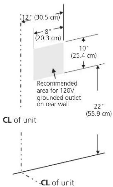
Figure 3
3. Clamp Down Information
Once the cooktop is installed in the counter opening, you must clamp the unit down as shown. To clamp down, insert the bracket with the offset side of the angle into the slots on each side of the unit. The thumb screw should then be run through the bracket, up against the bottom of the counter. Tighten until the unit draws down.
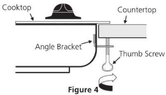
2. Installation
Insert the cooktop into the countertop opening. Note: After inserting the cooktop into the countertop opening, make sure the unit is sitting on the metal flange around the top of the burner box. Cooktop must not sit on the porcelain top. Avoid cutting an oversized hole in the countertop.
GAS COOKTOP INSTALLATION INSTRUCTIONS
4. Provide an Adequate Gas Supply
This cooktop is designed to operate on natural gas at 4" (10.2 cm) of manifold pressure only.
A pressure regulator is connected in series with the manifold on the cooktop and must remain in series with the supply line.
For proper operation, the maximum inlet pressure to the regulator must be no more than 14" (35.6 cm) of water column (W.C.) pressure.
For checking the regulator, the inlet pressure must be at least 1" (2.5 cm) (or 2.5 kPa) greater than the regulator manifold pressure setting. The regulator is set for 4" (10.2 cm) of manifold pressure, the inlet pressure must be at least 5" (12.7 cm).
The gas supply line to the cooktop should be 12 " (1.3 cm) or 34 " (7.9 cm) pipe.
5. LP/Propane Gas Conversion
This appliance can be used with Natural gas or LP/Propane gas. It is shipped from the factory for use with natural gas.
If you wish to convert your cooktop for use with LP/Propane gas, use the supplied fixed orifices in the package containing the installation Instructions Manual, in a bag marked "FOR LP/PROPANE GAS CONVERSION". Follow the installation instructions packaged with the orifices.
The conversion must be performed by a qualified service technician in accordance with the manufacturer's instructions and all local codes and requirements of the authority having jurisdiction. Failure to follow instructions could result in serious injury or property damage. The qualified agency performing this work assumes responsibility for the conversion.
WARNING Failure to make the appropriate conversion can result in personal injury and property damage.
Important: Remove all packing material and literature from cooktop before connecting gas and electrical supply to cooktop.
6. Install Pressure Regulator
Install the pressure regulator with the arrow on the regulator pointing up toward the unit in a position where you can reach the access cap.
WARNING FIRE HAZARD. Do not make the
connection too tight. The regulator is die cast.
Overtightening may crack the regulator resulting in a gas leak and possible fire or explosion.
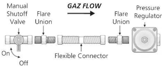
Assemble the flexible connector from the gas supply pipe to the pressure regulator in order: 1- manual shutoff valve, 2- 12 " nipple, 3- 12 " flare union adapter, 4- flexible connector, 5- 12 " flare union adapter, 6- 12 " nipple, pressure regulator.
flowchart
graph LR
    A["Manual Shutoff Valve"] --> B["Flare Union"]
    B --> C["Flexible Connector"]
    C --> D["Pressure Regulator"]
    D --> E["Flare Union"]
    E --> F["FLAME Connection"]
    style A fill:#f9f,stroke:#333
    style B fill:#ccf,stroke:#333
    style C fill:#cfc,stroke:#333
    style D fill:#fcc,stroke:#333
    style E fill:#cff,stroke:#333
    style F fill:#ffc,stroke:#333
All connections must be wrench-tightened
Figure 5
Use pipe-joint compound made for use with Natural and LP/Propane gas to seal all gas connections. If flexible connectors are used, be certain connectors are not kinked.
The supply line should be equipped with an approved shutoff valve. This valve should be located in the same room as the cooktop and should be in a location that allows ease of opening and closing. Do not block access to the shutoff valve. The valve is for turning on or shutting off gas to the appliance.
To Appliance
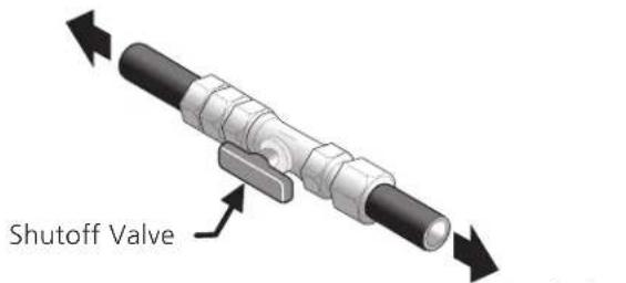
Figure 6
To gas supply line
Open the shutoff valve in the gas supply line. Wait a few minutes for gas to move through the gas line.
Check for leaks. Leak testing of the appliance shall be conducted according to the manufacturer's instructions. After connecting the cooktop to the gas supply, check the system for leaks with a manometer. If a manometer is not available, turn on the gas supply and use a liquid leak detector (or soap and water) at all joints and connections to check for leaks.
WARNING Do not use a flame to check for leaks from gas connections. Checking for leaks with a flame may result in a fire or explosion.
Tighten all connections if necessary to prevent gas leakage in the cooktop or supply line.
GAS COOKTOP INSTALLATION INSTRUCTIONS
Check alignment of valves after connecting the cooktop to the gas supply to be sure the cooktop manifold pipe has not been moved.
Disconnect this cooktop and its individual shutoff valve from the gas supply piping system during any pressure testing of that system at test pressures greater than 12 psig (3.5 kPa or 14" (35.6 cm) water column).
Isolate the cooktop from the gas supply piping system by closing its individual manual shutoff valve during any pressure testing of the gas supply piping system at test pressures equal to or less than 12 psig (3.5 kPa or 14" (35.6 cm) water column).
7. Connect Electricity to Gas Cooktop Electrical Requirements
120 volt, 60 Hertz, properly grounded branch circuit protected by a 15 amp circuit breaker or time delay fuse. Do not use an extension cord with this cooktop.
IMPORTANT Please read carefully.
For personal safety, this appliance must be properly grounded.
The power cord of this appliance is equipped with a 3-prong (grounding) plug which mates with a standard 3-prong grounding wall receptacle (see Figure 7) to minimize the possibility of electric shock hazard from the appliance.
The wall receptacle and circuit should be checked by a qualified electrician to make sure the receptacle is properly grounded.
Preferred Method
Grounding type wall receptacle
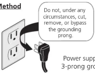
Power supply cord with 3-prong grounding plug
Figure 7
Where a standard 2-prong wall receptacle is installed, it is the personal responsibility and obligation of the consumer to have it replaced by a properly grounded 3-prong wall receptacle.
Do not, under any circumstances, cut or remove the third (ground) prong from the power cord.
CAUTION Disconnect electrical supply cord from wall receptacle before servicing cooktop.
8. Check Operation
Refer to the Use and Care Guide packaged with the cooktop for operating instructions and for care and cleaning of your cooktop.
- Remove foam caps.
- Turn on Electrical Power and Open Main Shutoff Gas Valve
- Check the Igniters
Operation of electric igniters should be checked after cooktop and supply line connectors have been carefully checked for leaks and the cooktop has been connected to electric power.
To operate the surface burner:
A. Push in and turn a surface burner knob to the LITE position. You will hear a small ticking noise; this is the sound of the electric ignitor which lights the burner.
B. After the burner lights, turn to the desired flame size. The controls do not have to be set at a particular mark. Use the marks as a guide and adjust the flame as needed.
GAS COOKTOP INSTALLATION INSTRUCTIONS
4. Adjust the "low" setting for regular surface burner valves (Figure 8)
a. Push in and turn control to LITE until burner ignites.
b. Quickly turn knob to LOWEST POSITION.
c. If burner goes out, reset control to OFF.
d. Remove the surface burner control knob.
e. Insert a thin-bladed screwdriver into the hollow valve stem and engage the slotted screw inside. Flame size can be increased or decreased with the turn of the screw. Turn counterclockwise to increase flame size. Turn clockwise to decrease flame size. Adjust flame until you can quickly turn knob from LITE to LOWEST POSITION without extinguishing the flame. Flame should be as small as possible without going out.

Note: Air mixture adjustment is not required on surface burners.
When All Hookups are Complete
Make sure all controls are left in the OFF position.
Make sure the flow of combustion and ventilation air to the cooktop is unobstructed.
Model and Serial Number Location
The serial plate is located on the underside of the cooktop.
When ordering parts for or making inquires about your range, always be sure to include the model and serial numbers and a lot number or letter from the serial plate of your cooktop.
Your serial plate also tells you the rating of the burners, the type of fuel and the pressure the cooktop was adjusted for when it left the factory.
Before You Call for Service
Read the Before You Call for Service Checklist and operating instructions in your Use and Care Guide. It may save you time and expense. The list includes common occurrences that are not the result of defective workmanship or materials in this appliance.
Refer to the warranty in your Use and Care Guide for our service phone number and address. Please call or write if you have inquiries about your product and/or need to order parts.
Figura 1
| MODELO A. | B.Archura | C.Profundidad | DIMENSIONES DEL HUECOD. Altura E. AnchuraMín. Máx. Mín. Máx. | F.Profundidad pordebajo de la plancha de cocinar | G.(Mín.) | H.(Mín.) | ||||
| 30" Modelos | 30 (76.2) | 112 (54.6) 2 | ^7/_8 (7.3) | 2714 (69.2) | 2812 (72.4) | 19 (48.3) | 19^3/_8 (49.2) 6 | 5 (16.5) 234 | (7) 214 (5.7) | |
| 36" Modelos | 36 (91.4) | 18 (45.7) | 2^7/_8 (7.3) 3414 | (87) 34 | ^3/_8 (87.3) | 16^5/_8 (42.2) | 1634 (42.5) | 6.5 (16.5) | 414 (10.8) | 3 (7.6) |
P/N 318201489 (1302) Rev. D
English – pages 1-8
Figure 1
P/N 318201489 (1302) Rev. D
English – pages 1-8
- FOR YOUR SAFETY:
- Appliances Installed in the state of Massachusetts:
- Important Notes to the Installer
- Important Note to the Consumer
- IMPORTANT SAFETY INSTRUCTIONS
- GAS COOKTOP INSTALLATION INSTRUCTIONS
- Typical Under Counter Installation of an Electric Built-in Oven with a Cooktop Mounted Above
- WARNING
- Wall Outlet Location
- Clamp Down Information
- Installation
- Provide an Adequate Gas Supply
- LP/Propane Gas Conversion
- Install Pressure Regulator
- Connect Electricity to Gas Cooktop Electrical Requirements
- For personal safety, this appliance must be properly grounded.
- Preferred Method
- Do not, under any circumstances, cut or remove the third (ground) prong from the power cord.
- Check Operation
- To operate the surface burner:
- Adjust the "low" setting for regular surface burner valves (Figure 8)
- When All Hookups are Complete
- Model and Serial Number Location
- Before You Call for Service
Brand : FRIGIDAIRE
Model : FFGC3015LS
Category : Cooker