
AKR 757 IX - Range hood WHIRLPOOL - Free user manual and instructions
Find the device manual for free AKR 757 IX WHIRLPOOL in PDF.


| Product type | Extractor hood |
| Brand | Whirlpool |
| Model | AKR 757 IX |
| Width | 90 cm |
| Depth | 50 cm |
| Height | 60 cm |
| Net weight | 15 kg |
| Power supply | 220-240 V / 50 Hz |
| Maximum motor power | 220 W |
| Number of speeds | 3 + intensive |
| Evacuation type | External ducting or recirculation |
| Evacuation diameter | 150 mm |
| Energy class | A+ |
| Max air flow | 650 m³/h |
| Max noise level | 65 dB(A) |
| Lighting | LED, 2 x 3 W |
| Filters | Metal grease filter (washable) + charcoal filter (optional) |
| Controls | Electronic touch controls |
| Filter maintenance | Wash grease filter every 2 months, replace charcoal filter every 4 months |
| Spare parts | Filters, bulbs, remote control available online |
| Warranty | 2 years |
Frequently Asked Questions - AKR 757 IX WHIRLPOOL
User questions about AKR 757 IX WHIRLPOOL
0 question about this device. Answer the ones you know or ask your own.
Ask a new question about this device
Download the instructions for your Range hood in PDF format for free! Find your manual AKR 757 IX - WHIRLPOOL and take your electronic device back in hand. On this page are published all the documents necessary for the use of your device. AKR 757 IX by WHIRLPOOL.
USER MANUAL AKR 757 IX WHIRLPOOL
natural_image
Line drawing of a kitchen air conditioner unit with ventilation duct and mounting bracket (no text or symbols)GB User and maintenance manual
IMPORTANT SAFETY INSTRUCTIONS
These instructions shall also be available on website: www.whirlpool.eu.
YOUR SAFETY AND THAT OF OTHERS IS HIGHLY IMPORTANT.
This manual and the appliance itself provide important safety warnings, to be read and observed at all times.

This is the attention symbol, pertaining to safety, which alerts users to potential risks to themselves and others.
All safety warnings are preceded by the attention symbol and the following terms:

DANGER:
indicates a hazardous situation which, if not avoided, will cause serious injury.

WARNING:
indicates a hazardous situation which, if not avoided, could cause serious injury.
All safety warnings specify the potential danger/warning to which they refer and indicate how to reduce the risk of injury, damage and electrical shock resulting from incorrect use of the appliance. Comply with the following instructions:
- Installation or maintenance must be carried out by a specialized technician, in compliance with the manufacturer's instructions and local safety regulations. Do not repair or replace any part of the appliance unless specifically requested in the user manual.
- The appliance must be disconnected from the power supply before carrying out any installation work.
• Earthing of the appliance is compulsory. (Not necessary for class II hoods identified by the □ symbol on the specifications label).
- The power supply cable must be long enough to permit connecting the appliance to the mains socket outlet.
- Do not pull the power supply cable in order to unplug the appliance.
- The electrical components must no longer be accessible to the user after installation.
- Do not touch the appliance with any wet part of the body and do not operate it when barefoot.
- This appliance may be used by children older than 8 years of age and by persons with reduced physical, sensory or mental capacities or with inadequate experience and knowledge only if they are supervised or if they have been taught how to use the appliance in conditions of safety and if they are aware of the dangers involved. Children must not play with the appliance. Cleaning and maintenance must not be carried out by children, unless they are supervised by adults.
- Do not repair or replace any part of the appliance unless specifically indicated in the manual. Defective parts must be replaced using genuine parts. All other maintenance services must be carried out by a specialized technician.
- Children must be supervised to ensure they do not play with the appliance.
- When drilling through a wall or the ceiling, pay attention not to damage electric connections and/or pipes.
- The ventilation ducts must always discharge to the outside.
- Exhaust air must not be vented through a flue used for removal of fumes produced by appliances burning gas or other fuels, but must have a separate outlet. All national regulations governing extraction of fumes must be observed.
- If the hood is used together with other appliances operating on gas or other fuels, the negative pressure in the room must not exceed 4 Pa (4 x 10⁻⁵ bar). For this reason, make sure the room is adequately ventilated.
- The Manufacturer declines any liability for improper use or incorrect setting of the controls.
- Regular cleaning and maintenance is essential to correct functioning and good performance of the appliance. Frequently clean all encrustations from dirty surfaces to prevent the accumulation of grease. Regularly clean or replace the filters.
- Never flame cook food (flambé) under the appliance. Using free flames might cause fire.
- Do not leave frying pans unattended when frying, as the frying oil may catch fire.
- Failure to observe the instructions for cleaning the hood and replacing the filters may result in a fire.
• The fume extractor hood must never be opened without the grease filters installed and it should be kept under constant supervision.
- Gas appliances must be used under the extractor hood only with pans resting.
- When using more than three gas cooking points, the hood should be operating at power level 2 or greater. This will eliminate heat congestion in the appliance.
- Before touching the bulbs, first ensure that they are cold.
- Do not use or leave the hood without its lamps correctly installed - risk of electric shock.
- Wear work gloves for all installation and maintenance operations.
- The product is not suitable for outdoor use.
- When the hob is in use, accessible parts of the hood may become hot.
KEEP THIS BOOKLET FOR FUTURE CONSULTATION.
Declaration of conformity C€
- This appliance has been designed, manufactured and marketed in compliance with:
- safety objectives of the "Low Voltage" Directive 2006/95/EC (which replaces 73/23/EEC and subsequent amendments);
- the ecodesign requirements of european regulations n. 65/2014, and n. 66/2014 in conformity to the european standard EN 61591
- the protection requirements of Directive "EMC" 2004/108/EC.
Electrical safety of the appliance can only be guaranteed if it is correctly connected to an approved earthing system.
Energy saving tips
- Switch ON the hood at minimum speed when you start cooking and kept it running for few minutes after cooking is finished.
- Increase the speed only in case of large amount of smoke and vapour and use boost speed(s) only in extreme situations.
- Replace the charcoal filter(s) when necessary to maintain a good odour reduction efficiency.
- Clean the grease filter(s) when necessary to maintain a good grease filter efficiency.
- Use the maximum diameter of the ducting system indicated in this manual to optimize efficiency and minimize noise.
INSTALLATION
After unpacking the appliance, check for any transport damage. In the event of problems, contact the dealer or your nearest After-sales Service. To prevent any damage, only remove the appliance from its polystyrene foam packaging at the time of installation.
PREPARING FOR INSTALLATION

WARNING:
this is a heavy product; the hood should only be lifted and installed by two or more people.
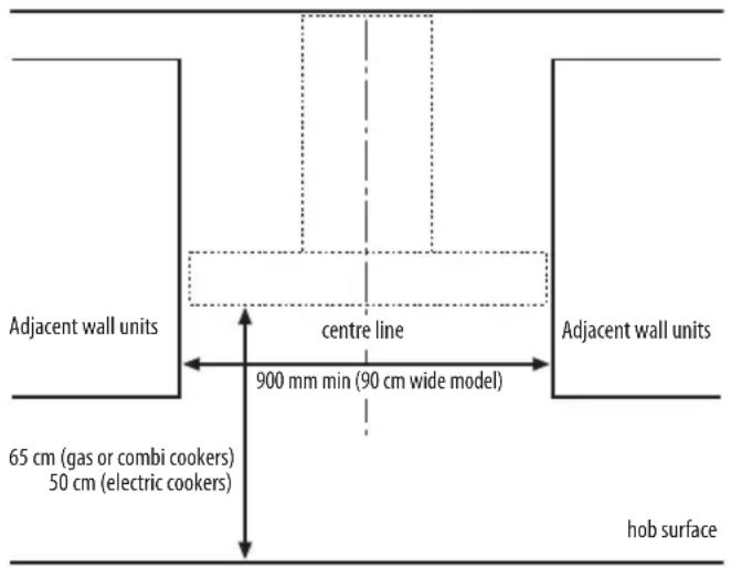
The minimum distance between the support of the cooking pans on top of the cooker and the bottom of the hood must not be less than 50 cm for electric cookers and 65 cm for gas or mixed cookers. Before installation also check the minimum distances stated in the manual of the cooker.
If the installation instructions for the cooker specify a greater distance between cooker and hood, this distance must be observed.
ELECTRICAL CONNECTION
Make sure the power voltage specified on the appliance rating plate is the same as the mains voltage.
This information may be found on the inside of the hood, under the grease filter.
Power cable replacement (type H05 VV-F 3 x 0,75 mm 2 ) must be carried out by a qualified electrician. Contact an authorized service centre.
If the hood is fitted with an electric plug, connect the plug to a socket complying with current regulations, located in an accessible place after installation. If no plug is fitted (direct wiring to the mains), or if the socket is not located in an accessible place, install a standardised double pole power switch that will enable complete isolation from the mains in case of category III overvoltage conditions, in accordance with installation rules.
GENERAL RECOMMENDATIONS
Before use
Remove cardboard protection pieces, protective film and adhesive labels from accessories. Check the appliance for any transport damage.
During use
To avoid any damage do not place any weights on the appliance. Do not expose the appliance to atmospheric agents.
SAFEGUARDING THE ENVIRONMENT
Disposal of packing
The packing material is 100% recyclable and is marked with the recycle symbol △. The various parts of the packing must therefore be disposed of responsibly and in full compliance with local authority regulations governing waste disposal.
Scrapping the product
- This appliance is marked in compliance with European Directive 2012/19/EU, Waste Electrical and Electronic Equipment (WEEE).
- By ensuring this product is disposed of correctly, you will help prevent potential negative consequences for the environment and human health, which could otherwise be caused by inappropriate waste handling of this product.
- The symbol 📋 on the product or on the accompanying documentation indicates that it should not be treated as domestic waste but must be taken to an appropriate collection centre for the recycling of electrical and electronic equipment.
Scrapping of household appliances
- This appliance is manufactured with recyclable or reusable materials. Dispose of it in accordance with local waste disposal regulations. Before scrapping, cut off the power supply cable.
- For further information on the treatment, recovery and recycling of household electrical appliances, contact your competent local authority, the collection service for household waste or the store where you purchased the appliance.
TROUBLESHOOTING GUIDE
The appliance does not work:
- Check for the presence of mains electrical power and if the appliance is connected to the electrical supply;
- Turn off the appliance and restart it to see if the fault persists.
The hood's suction level is not sufficient:
- Check the suction speed and adjust as necessary;
- Check that the filters are clean;
- Check the air vents for any obstructions.
The light does not work;
- Check the light bulb and replace if necessary;
- Check that the light bulb has been correctly fitted.
AFTER-SALES SERVICE
Before calling the After-Sales Service:
- See if you can solve the problem yourself with the help of the suggestions given in the "Troubleshooting guide".
- Switch the appliance off and back on again it to see if the fault persists.
If after the above checks the fault still occurs, get in touch with the nearest After-Sales Service.
Always specify:
• A brief description of the fault;
• The exact type and model of the appliance;
- The service number (number after the word "Service" on the rating plate), located on the inside of the appliance. The service number is also indicated on the guarantee booklet;
- Your full address;
- Your telephone number.

0000 000 00000

If any repairs are required, please contact an authorised After-sales Service (to guarantee that original spare parts will be used and repairs carried out correctly).
CLEANING

WARNING
- Never use steam cleaning equipment.
- Disconnect the appliance from the power supply.
IMPORTANT: do not use corrosive or abrasive detergents. If any of these products accidentally comes into contact with the appliance, clean immediately with a damp cloth.
• Clean the surfaces with a damp cloth. If it is very dirty, add a few drops of washing up detergent to the water. Finish off with a dry cloth.
IMPORTANT: do not use abrasive sponges or metallic scrapers or scourers. Over time, these can ruin the enamel surface.
- Use detergents specifically designed for cleaning the appliance and follow the manufacturer instructions.
IMPORTANT: clean the filters at least monthly to remove any oil or grease residuals.
MAINTENANCE

WARNING
- Use protective gloves.
- disconnect the appliance from the power supply.
GREASE FILTERS
The metal grease filter has an unlimited life and should be cleaned once a month by hand or in a dishwasher at low temperature and with a short cycle. Cleaning in a dishwasher may cause discolouring of the grease filter, but its filtering efficiency is unaffected.
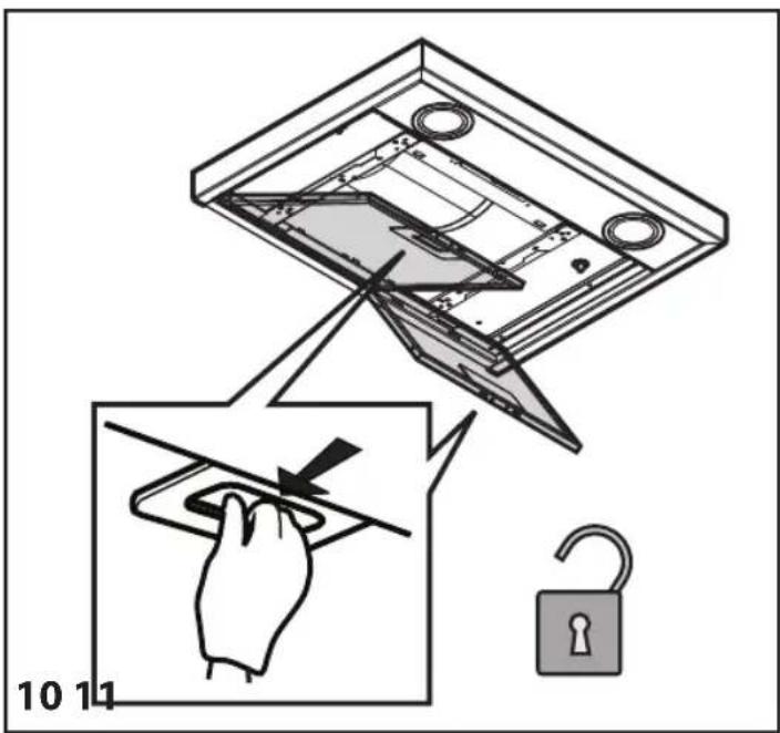
Pull out the handle to remove the filter.
Wash the filter and leave it to dry, proceeding in reverse order to refit it.
REPLACING HALOGEN LAMPS
IMPORTANT: Use 20W MAX - G4 halogen lamps only.
- Disconnect the hood from the household power supply.
- Use a small screwdriver to gently prise (near the three points indicated) the lamp cover off.
- Remove the burnt-out lamp and fit a new one.
- Refit (snap-on) the lamp cover.

natural_image
Pure diagram of a mechanical or electrical component with downward arrows indicating direction (no text or symbols)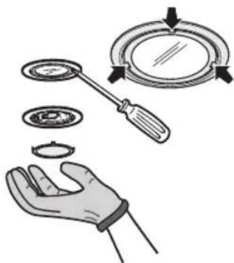
natural_image
Illustration of a hand holding a magnifying glass over a circular object, with arrows indicating motion (no text or symbols)ACTIVATED CARBON FILTER (filter hoods only):
The carbon filter must be cleaned once a month in a dishwasher at the highest temperature, using a normal dishwasher detergent. It is advisable to clean the filter separately.
After cleaning, reactivate the carbon filter by drying it in the oven at 100irc C for 10 minutes. Change the carbon filter every 3 years.
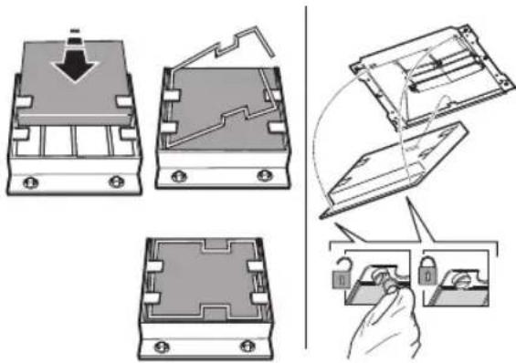
Fitting the carbon filter:
- Remove the grease filter.
- Hook the carbon filter firstly to the metal tab at the back on the hood and then fix it at the front with the two knobs.
- Refit the grease filter
MATERIAL SUPPLIED
Remove all the components from the packets. Check that all the components are included.
- Hood assembled with motor, lamps and grease filters installed.
- Instructions for assembly and use
- 1 electrical cable
• 1 Assembly template - 6 wall plugs ∅ 8mm
- 6 screws ∅ 5 x 45
- 1 cable clamp
- 1 screw ∅ 3.5 x 9.5
• 1 Flue support bracket - 2 screws ∅ 2.9 x 6.5
- 2 washers
• Filter Version only : 1 deflector + 2 screws ∅ 2.9 x 6.5
INSTALLATION - PRELIMINARY ASSEMBLY INSTRUCTIONS
The hood is designed for installation and use in "Extractor version" or in "Filter version".
Note: The model with electric shutter can only be used in "Extractor version" and the exhaust pipe must be connected to a peripheral extraction unit.
Extractor Version
Fumes are extracted and expelled to the outside through an exhaust pipe (not supplied) fixed to the hood exhaust pipe connector.
Depending on the exhaust pipe purchased, provide for suitable fixing to the exhaust pipe connector.
IMPORTANT: If already installed, remove the carbon filter/s.
Filter Version
Air is filtered through the carbon filter/s and recycled into the surrounding environment.
IMPORTANT: check that air recirculation is facilitated.
If the hood does not have a carbon filter/s, order one/them and fit it/them before use.
Install the hood away from very dirty locations, windows, doors and sources of heat.
The hood comes supplied with all the materials required for installation on most walls/ceilings. However, a qualified technician is needed to make sure that the plugs are suitable for your ceiling.
INSTALLATION DIMENSIONS
INSTALLATION - ASSEMBLY INSTRUCTIONS
The instructions below, to be carried out in the order in which they are numbered, refer to the figures (with the same step numbers) given on the last pages of this manual.
Note: Some instructions differ depending on the product width or hood box height, in which case installation differences are given in the text and in the figures.
- Mark a line on the wall, up to the ceiling, corresponding to the centre line.
- Place the drilling template against the wall (fix it with adhesive tape): the vertical centre line on the template must match the centre line drawn on the wall, and the bottom edge of the drilling template must match the bottom edge of the hood.
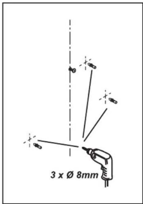
Drill a hole.
- Remove the drilling template and insert plugs and screws as indicated.
- Tighten a little
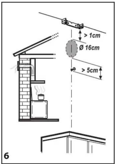
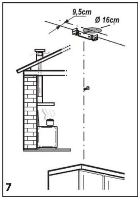
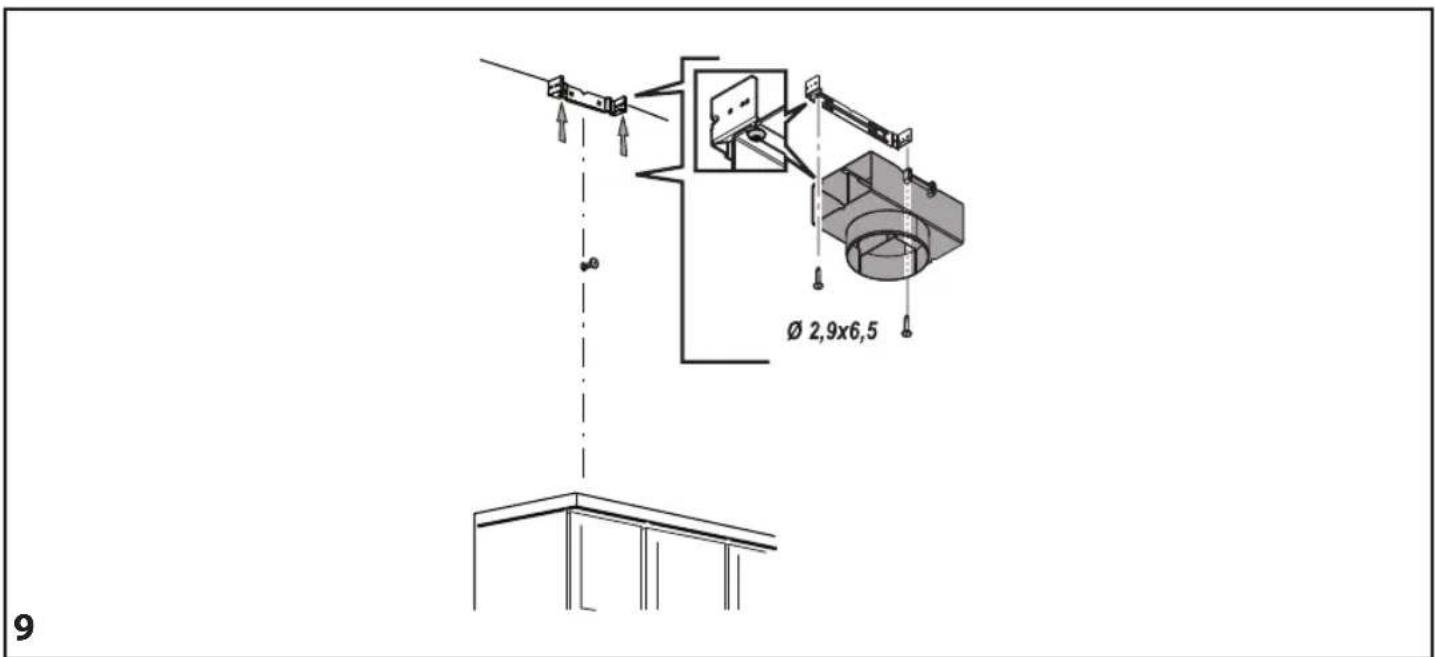
- Place the flue support bracket on the wall, against the ceiling. Drill and insert the wall plugs as indicated. Fix the bracket.
- Extractor Version only - rear exhaust: Make a hole in the rear wall for the flue pipe.
- Extractor Version only - exhaust towards the ceiling: Make a hole in the ceiling for the flue pipe.
- Prepare the connection to the household electrical system.
- Filter Version only: Fix the deflector to the flue support bracket.
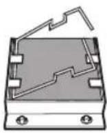
- Remove the grease filter/s.
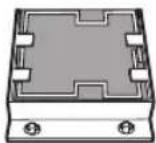
- Remove the tape fixing the control electronics box to the motor body.
Note: The drawing is only a guide, and the box may be temporarily fixed to other sides of the motor body.
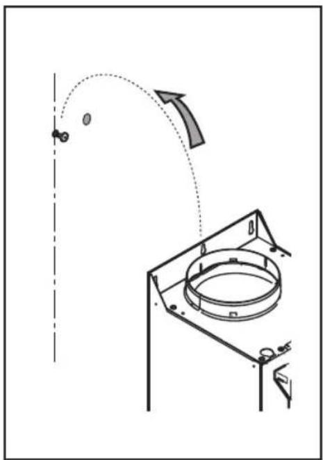
- Hook the hood to the wall.
- Adjust the hood horizontally.
- Adjust the distance between the hood and the wall.
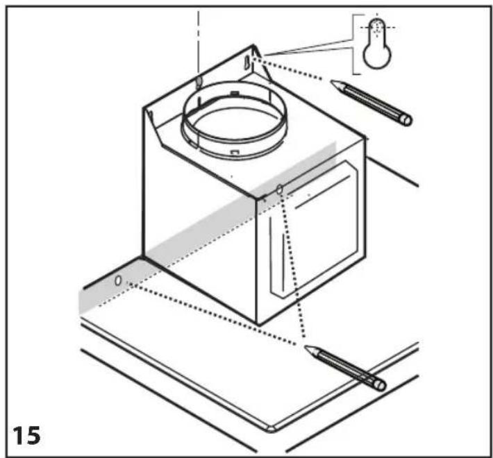
- Mark the hole/s for final fixing of the hood as indicated.
- Remove the hood from the wall.
- Drill and insert the wall plugs as indicated.
- Rehook the hood to the wall.
- Secure the hood to the wall with screws as indicated.
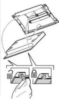
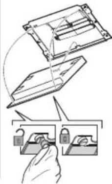
- Tighten down the already partially tightened screws fixing the box to the motor body.
Note: There are two types of boxes, with front or rear fixing. Follow the instructions in the figures (20a and 20b) according to your model.
- Insert the power cable in its special place.
- Secure the cable to the cable clamp.
IMPORTANT: This operation is compulsory. It will prevent accidental disconnection of the power cable.
Carry out the connection to the household electrical system.
- Connect the fume exhaust pipe to the collar; the pipe must be run towards the outside (extractor version) or towards the deflector (filter version).
- Fit the flues in place over the hood, completely covering the extractor unit.
- Remove the upper section and fix the flues with the screws as indicated.
- Fit the carbon filter (Filter Version only) and refit the grease filter/s.
Check hood operation, referring to the section giving a description of the hood and its use.
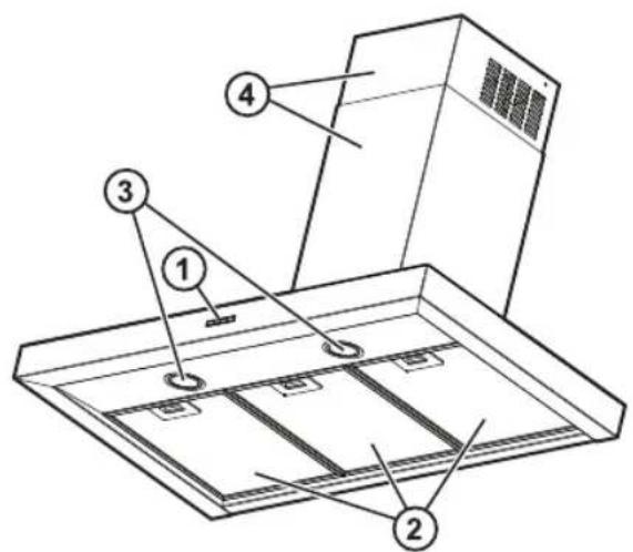
DESCRIPTION AND USE OF HOOD
- Control panel.
- Grease filters.
- Halogen lamps.
- Telescopic flue.
Control panel
- OFF / Extraction speed (power) decrease button
- ON / Extraction speed (power) increase button
Note: The intensive extraction speed (power) is timed and lasts for 5 minutes
(indicator c flashes); the hood then reverts to extraction speed (power) 2.


- Timer ON/OFF button: delays deactivation of the selected extraction speed (power) by 5 minutes.
Note: The button also has the "Reset filter saturation signaling" function
- Light ON/OFF button
- Display, shows:
a. Extraction speed (power): the indicator rotates according to the selected extraction speed (power).
Safety operation: the indicator flashes.
b. Grease filter saturation: comes on when filter maintenance is required.
c. Timer
d. Active carbon filter saturation: comes on when filter maintenance is required.
Note: This function is normally disabled and should only be activated if the hood is used as a filter version (with carbon filter fitted).
To do so, proceed as follows:
- switch off the hood
- keep the buttons 1 and 3 pressed at the same time until the indicator goes from flashing (indicator disabled) to fixed light (indicator enabled).
- release the buttons.
To deactivate it, repeat the procedure: the indicator will go from fixed light (indicator enabled) to flashing (indicator disabled).
e. Lighting
Safety operation
The hood has a sensor which, in case of a sudden increase in temperature, activates extraction until the temperature drops significantly.
Filter saturation signaling reset
After carrying out filter maintenance, keep the button 3 pressed until the indicator goes off.
CONSIGNES DE SÉCURITÉ IMPORTANTES
natural_image
Pure diagram of a mechanical or electrical component with downward arrows indicating direction (no text or symbols)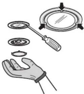
natural_image
Illustration of a hand holding a magnifying glass over a circular object, with arrows indicating motion (no text or symbols)MATÉRIEL DE SÉRIE
Bandeau de commande
natural_image
Pure diagram of a mechanical or electrical component with downward arrows indicating direction (no text or symbols)VERVANGEN VAN DE HALOGEENLAMPJES
natural_image
Illustration of a hand holding a circular object with a screwdriver, alongside a magnifying glass and a separate circular object (no text or symbols)natural_image
Technical illustration showing three views of a mechanical component with a hand holding a lock (no text or symbols present)BIJGELEVERD MATERIAAL
Bedieningspaneel
natural_image
Pure diagram of a mechanical or electrical component with downward arrows indicating direction (no text or symbols)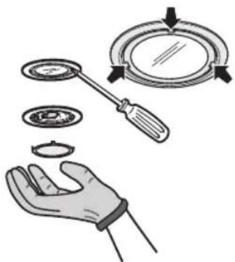
natural_image
Illustration of a hand holding a circular object with a screwdriver, alongside a magnifying glass and a separate view of the disc (no text or symbols)natural_image
Two technical diagrams showing a mechanical component with a downward arrow and a stepped section, no text or symbols present.

natural_image
Diagram showing a hand holding a padlock with two views of a device (no text or symbols present)MATERIAL SUMINISTRADO
Panel de mandos
GUIDA RICERCA GUASTI
natural_image
Pure diagram of a mechanical or electrical component with downward arrows indicating direction (no text or symbols)
natural_image
Illustration of a hand holding a magnifying glass over three circular objects, with arrows indicating motion (no text or symbols)
natural_image
Two views of a mechanical component with a downward arrow and internal structure (no text or symbols)
natural_image
Diagram showing a hand holding a padlock and a device with a curved arrow indicating motion (no text or symbols)MATERIALE A CORREDO
Pannello comandi
natural_image
Pure diagram of a mechanical or electrical component with downward arrows indicating direction (no text or symbols)
natural_image
Illustration of a hand holding a magnifying glass over a circular object, with arrows indicating direction (no text or symbols)natural_image
Two technical diagrams showing a mechanical component with a downward arrow and a stepped outline, no text or symbols present.

natural_image
Diagram showing a hand holding a padlock and a device with a lock, illustrating the process (no text or symbols present)MATERIAL WCHODZACY W SKŁAD ZESTAWU
Panel sterowania
natural_image
Pure diagram of a mechanical or electrical component with downward arrows indicating direction (no text or symbols)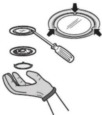
natural_image
Illustration of a hand holding a circular object with a magnifying glass above it, no text or symbols present.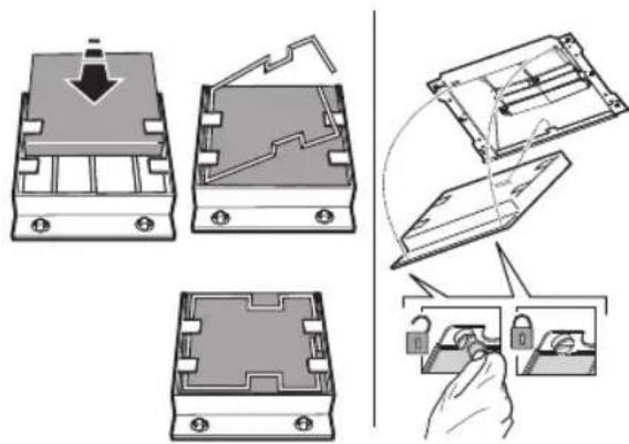
MATERIÁL V PŘÍSLUŠENSTVÍ
Ovládací panel
DÔLEŽITÉ BEZPEČNOSTNÉ POKYNY
natural_image
Pure diagram of a mechanical or electrical component with downward arrows indicating direction (no text or symbols)
natural_image
Illustration of a hand holding a magnifying glass over a circular object, with arrows indicating motion (no text or symbols)
natural_image
Two technical diagrams showing a mechanical component with a downward arrow and a stepped section, both without any text or symbols.
MATERIÁL VO VÝBAVE
Ovládací panel
natural_image
Pure diagram of a mechanical or electrical component with downward arrows indicating direction (no text or symbols)
natural_image
Illustration of a hand holding a circular object with a tool, alongside a magnifying glass and a separate view (no text or symbols)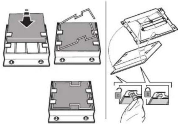
natural_image
Technical illustration showing three views of a mechanical component with a hand holding a lock (no text or symbols present)TARTOZÉKKÉNT ADOTT ANYAGOK
Kezelőlap
natural_image
Pure diagram of a mechanical or electrical component with downward arrows indicating direction (no text or symbols)
natural_image
Illustration of a hand holding a magnifying glass over a circular object, with arrows indicating motion (no text or symbols)
ПРИЛОЖЕНИ МАТЕРИАЛИ
Командно табло
natural_image
Pure diagram of a mechanical or electrical component with downward arrows indicating direction (no text or symbols)
natural_image
Illustration of a hand holding a magnifying glass over a circular object, with arrows indicating motion (no text or symbols)natural_image
Diagram showing a hand holding a device with two lock icons, illustrating the process (no text or symbols present)MATERIALE FURNIZATE
Panoul de comandă




natural_image
Illustration of a hand inserting a cable into a device with an arrow indicating rotation (no text or symbols present)

natural_image
Diagram showing a mechanical device interacting with a rectangular block, with directional arrows indicating motion or force (no text or symbols present)

natural_image
Technical diagram showing a mechanical assembly with a rotating component and an arrow indicating motion (no text or symbols)19


natural_image
Technical diagram showing a mechanical assembly with two views: top view shows a rotating tool, bottom view shows a rotating base with a curved component (no text or symbols)

natural_image
Technical diagram of a mechanical device with a connector and cable, labeled '21a' (no text or symbols on the diagram itself)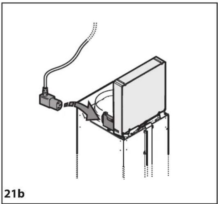
natural_image
Diagram of a mechanical assembly with a connector and wiring, labeled '21b' (no text or symbols on the diagram itself)22

23

24

natural_image
Technical diagram of a mechanical assembly with a cylindrical component and a box, showing internal components and motion direction (no text or labels)25 26


natural_image
Diagram showing a device with internal components and a hand holding a tool, alongside a padlock (no text or symbols)



- IMPORTANT SAFETY INSTRUCTIONS
- YOUR SAFETY AND THAT OF OTHERS IS HIGHLY IMPORTANT.
- DANGER:
- WARNING:
- Declaration of conformity C€
- Energy saving tips
- INSTALLATION
- PREPARING FOR INSTALLATION
- this is a heavy product; the hood should only be lifted and installed by two or more people.
- ELECTRICAL CONNECTION
- GENERAL RECOMMENDATIONS
- Before use
- During use
- SAFEGUARDING THE ENVIRONMENT
- Disposal of packing
- Scrapping the product
- Scrapping of household appliances
- TROUBLESHOOTING GUIDE
- The appliance does not work:
- The hood's suction level is not sufficient:
- The light does not work;
- AFTER-SALES SERVICE
- Before calling the After-Sales Service:
- CLEANING
- WARNING
- MAINTENANCE
- GREASE FILTERS
- REPLACING HALOGEN LAMPS
- IMPORTANT: Use 20W MAX - G4 halogen lamps only.
- ACTIVATED CARBON FILTER (filter hoods only):
- Fitting the carbon filter:
- MATERIAL SUPPLIED
- INSTALLATION - PRELIMINARY ASSEMBLY INSTRUCTIONS
- Extractor Version
- Filter Version
- IMPORTANT: check that air recirculation is facilitated.
- INSTALLATION DIMENSIONS
- INSTALLATION - ASSEMBLY INSTRUCTIONS
- DESCRIPTION AND USE OF HOOD
- Control panel
- Safety operation
- Filter saturation signaling reset
- CONSIGNES DE SÉCURITÉ IMPORTANTES
- MATÉRIEL DE SÉRIE
- Bandeau de commande
- VERVANGEN VAN DE HALOGEENLAMPJES
- BIJGELEVERD MATERIAAL
- Bedieningspaneel
- MATERIAL SUMINISTRADO
- Panel de mandos
- GUIDA RICERCA GUASTI
- MATERIALE A CORREDO
- Pannello comandi
- MATERIAL WCHODZACY W SKŁAD ZESTAWU
- Panel sterowania
- MATERIÁL V PŘÍSLUŠENSTVÍ
- Ovládací panel
- DÔLEŽITÉ BEZPEČNOSTNÉ POKYNY
- MATERIÁL VO VÝBAVE
- TARTOZÉKKÉNT ADOTT ANYAGOK
- Kezelőlap
- ПРИЛОЖЕНИ МАТЕРИАЛИ
- Командно табло
- MATERIALE FURNIZATE
- Panoul de comandă
Brand : WHIRLPOOL
Model : AKR 757 IX
Category : Range hood