
TR 90 DX - Cooker TEKA - Free user manual and instructions
Find the device manual for free TR 90 DX TEKA in PDF.


| Product type | Mixed cooker (gas + electric) |
| Brand | Teka |
| Model | TR 90 DX |
| Width | 90 cm |
| Height | 85 cm |
| Depth | 60 cm |
| Weight | 55 kg |
| Cooking type | Gas for hob, electric for oven |
| Number of burners | 5 gas burners |
| Oven type | Multifunction electric oven |
| Oven capacity | 75 liters |
| Oven functions | Convection, grill, fan-assisted, defrost |
| Power supply | Gas (G20/G30) and 230 V / 400 V |
| Burner power | From 1.0 kW to 3.5 kW |
| Energy class | A |
| Cleaning | Catalytic wall and easy-clean enamel |
| Safety | Gas safety device (thermocouple), child lock |
| Spare parts | Available (grills, burners, glass, etc.) |
| Warranty | 2 years |
| Repairability index | 7.5 / 10 |
| Country of manufacture | Spain |
Frequently Asked Questions - TR 90 DX TEKA
User questions about TR 90 DX TEKA
0 question about this device. Answer the ones you know or ask your own.
Ask a new question about this device
Download the instructions for your Cooker in PDF format for free! Find your manual TR 90 DX - TEKA and take your electronic device back in hand. On this page are published all the documents necessary for the use of your device. TR 90 DX by TEKA.
USER MANUAL TR 90 DX TEKA
4.2 Installation


Fig. 4
You now own a glass ceramic hob with Touch-Control panel.
Chapters 2 and 3 of these Operating Instructions contain information on how you can make sure that your hob provides many years of service.
These Operating Instructions are for use with several types of hobs. The rating label on the front of these Instructions will show you which type you have bought.
Contents
1. Operations
1.1 Your new hob with Touch-Control operation 1.2 Touch-Control panel 1.3 Touch-Control operations
2. Things to watch out for
2.1 Notes on the right types of saucepans 2.2 Important
3. Cleaning and maintenance
4. Fitting
4.1 Worktop cut-out 4.2 Installation 4.3 Electrical connection 4.4 Maintenance and repair work
Safety instructions

Attention!
People who are not familiar with the built-in hob must only be allowed to operate it under supervision.
Generally keep little children away from the appliance and never allow them to play with the appliance.
Instructions on environmental protection
The symbol on the product or on its packaging indicates that this product may not be treated as household waste. Instead it shall be handed over to the applicable collection point for the recycling of electrical and electronic equipment. By ensuring this product is disposed of correctly, you will help prevent potential negative consequences for the environment and human health, which could otherwise be caused by inappropriate waste handling of this product. For more detailed information about recycling of this product, please contact your local city office, your household waste disposal service or the shop where you purchased the product.
Disposal
Please dispose of the packaging that came with your appliance in an environmentally friendly way.
Recycling in this way saves on resources and cuts down on waste.
1. Operations
1.1 Your new hob with Touch-Control operation
This manual covers the model: GKST 85.. and GKST 90 D.
1.2 Touch-Control panel
After the supply voltage has been connected (mains connection), a self-test is carried out which is concluded when a short acoustic signal is to be heard. (Calibration adjustment). Afterwards, the control unit is then in standby mode. During calibration adjustment a minus sign is lit in the cooking level display ④. It goes out if calibration is successfully executed. The touch keys may not be covered by objects or anything else during calibration.
①⑨On/off key (emergency off)
②⑨Plus key
③⑨Minus key
④⑨Cooking level display
⑤ Locking key
⑥ Control lamp lock
⑦⑨Multi-circuit key
⑧⑨Multi-circuit control lamp
⑨ Timer key
⑩ Time display
⑩/1 Control lamp for left cooking zone
⑩/2 Control lamp for middle cooking zone
⑩/3 Control lamp for right cooking zone

GKST 85..

GKST 90 D
1.3 Touch-Control operations
Each key operation is always confirmed by an acoustic signal.
Pressing the on/off key ① switches on the control system.
At all cooking level displays ④ and the timer display ⑩ a "0" lights up. The next action must be carried out within ten seconds, otherwise the control system will automatically switch off again.
If the minus key ③ is pressed, cooking level 4 is indicated.
Then, a cooking level between 0 and 9 can be selected with the plus or minus key.
The minus key ③ can be used to turn the cooking level down to "0"; if the minus and plus keys ②/③ are pressed at the same time, the cooking level can be switched off directly.
A "0" appears that goes out after 10 seconds.
In all cases the complete control system can be switched off at any time by pressing the on/off key ①.
Parboiling boost
This function makes cooking easier. The cooking zone is automatically heated at full power and at a specified time (see table) it is switched back to the cooking level which you pre-select.
If a cooking zone is switched on with the plus key ②, cooking level 9 will appear. The parboiling boost will have been activated and the decimal point will light up in the cooking level display. Any additional keys now have to be pressed within 10 seconds, otherwise the decimal point goes out and the parboiling boost is no longer activated.
Select a cooking level between 9 and 0 with the minus key ③.
The parboil impulse remains activated and the decimal point is lit. If a key is pressed after the decimal point is no longer lit then the parboiling boost is no longer activated.
If the cooking level is changed during the parboiling boost then the parboiling time is automatically (see table) calculated.
Table of times PB== Parboiling boost, in seconds
| Cooking level=PB (s) | |
| 1 | 82 |
| 2 | 164 |
| 3 | 264 |
| 4 | 328 |
| 5 | 410 |
| 6 | 82 |
| 7 | 164 |
| 8 | 164 |
| 9 | — |
Two-circuit / three-circuit connection
Two-circuit / three-circuit connection of the respective cooking zone can only be effected after the corresponding cooking zone has been switched on.
Select the desired cooking level 1-9. Switch on the second heating element by means of the Multi-circuit key ⑦. The control lamp ⑧ of the selected cooking zone lights up. Connect the third heating circuit by pressing the Multi-circuit key ⑦ once again. The second control lamp ⑧ lights up. The corresponding cooking zone must also be activated in order to switch off the two-circuit / three-circuit connection. The outer heating circuits are switched off by pressing the Multi-circuit key ⑦ once again. The control lamps ⑧ are then no longer lit.
Timer
The timer can be used to automatically switch off a cooking zone after a pre-set time of between 1 and 99 minutes. The required cooking zone must be activated. Press Timer key ⑨ repeatedly until control lamp ⑩/1/2/3 of the required cooking zone lights up. The timer display ⑩ shows "00". Select the required cooking time between 01 and 99 minutes by means of the Minus or Plus key ③/②. The control lamp ⑩/1/2/3 of the selected cooking zone lights up.
The selected cooking time can be altered at any time. Cooking time can be controlled for only one cooking zone at a time.
When the pre-set cooking time has finished, the cooking zone switches off automatically and an acoustic signal sounds for 10 seconds. This can be switched off by pressing any key.
If you want to switch the timer off beforehand, the minus key ③ or the timer key ⑨ can be used to set the timer to "00".
The timer can also be used as an egg timer when none of the cooking zones are activated. In this case, no cooking zone should be activated when the timer 9 is being set.
Locking
By pressing the locking key ⑤ for approx. 2 seconds (lock indicator ⑥ lights up) all of the buttons, except for the on/off key, are then locked against accidental use.
The lock indicator then goes out after approx. 2 seconds, the lock is, however, still on. If any key will be pressed the lock indicator ⑥ lights up again for approx. 2 seconds.
The following keys can still be used:
- Switch off with on/off key (emergency shutdown)
- Switch off by pressing the plus and minus key simultaneously. •=Unlock
The lock is released by pressing the locking key ⑤ again.
The lock indicator lights up for approx. 2 seconds and then goes out again.
The lock is now no longer activated.
Residual heat display
The glass ceramic hob is equipped with a "H" residual heat display.
The ceramic hob is not directly heated, though it becomes hot due to the effect of heat reflected by the pan.
As long as the “H” lights up after the cooking zone has been switched off, the residual heat can be used for melting food or for keeping food warm.
The cooking zone may still be hot when the letter "H" no longer lights up. Risk of burns!
Safety switch-off
The maximum operating time for each individual cooking zone is limited, and details are shown in the enclosed table of times. When the safety switch-off has switched off the touch control system, an "H" is shown in the cooking level display ④ if there is still any residual heat left. Pressing the on/off key makes the control system ready for operation again.
If more than one key is pressed simultaneously - with the exception of the minus and plus keys - the control system will not accept this as a valid command. If one or more keys are activated for longer than 10 seconds, for example by boiling over or the weight for a pan, the control system assumes that there is an error and switches off automatically.
Table of times MOT = maximum operating time, in hours
| Cooking level MOT (h) | |
| 1 | 10 |
| 2 | 5 |
| 3 | 5 |
| 4 | 4 |
| 5 | 3 |
| 6 | 2 |
| 7 | 2 |
| 8 | 2 |
| 9 | 1 |
2. Things to watch out for
2.1 Notes on the right types of saucepans
Use only pots and pans with bottoms that are firm, even and as thick as possible. This applies particularly to cooking with high temperatures, e.g. deep-frying. Uneven bottoms extend cooking times and increase energy consumption. The best transmission result is obtained when the pots and the cooking zone are of equal dimension. Always use a lid. Energy is wasted if you cook without a lid placed correctly on the pan.
In order to work directly on the cooking zones, you can use cooking utensils made from fireproof glass or porcelain if their bottoms are flat polished. Please observe the manufacturer's instructions.
Always take away overflow food.
Clean the hob before using it for the first time. Then switch the cooking zones onto the highest setting, one after the other, for three minutes. This will remove any "new" smell and cause any humidity in the heating units to evaporate. This is necessary so that the electronic circuits function properly.
2.2 Important
Attention! The surfaces of the heating and cooking zones become hot during use. Keep small children away at all times.
Always ensure that no hard objects are dropped onto the cooking surface. Under certain circumstances the material is sensitive to mechanical stresses and strains. A heavy knock or blow in a small area can cause the ceramic hob to break. If careless treatment results in a break, split or crack, the ceramic hob must immediately be taken out of use and disconnected from the mains power supply. To do this, switch off the safety switch for the oven connection in the fuse box. Customer Service must be contacted.
Objects made out of metal, like knives, forks, spoons and lids should not be placed on the cooking zones, because they might become hot.
The cooking zone must be switched off after use by means of the touch-control. This is to avoid accidental activation.
Do not use the glass ceramic hob as a storage area! Never prepare food in aluminium foil and plastic containers on the hot cooking zone.
Do not switch the hob on without using it for cooking. Do not place combustible, volatile or heat deformable objects directly underneath the hob.
When preparing food with fat or oil stay nearby. Overheated oil can ignite. Never pour water into burning fat or oil. Risk of burning! Cover the dish in order to extinguish the fire and switch off the cooking zone. Let the dish cool down on the cooking zone.
In addition, make sure that leads from electrical appliances plugged into nearby sockets cannot come into contact with the hotplates.
Never clean the glass ceramic hob with a steam cleaner or similar appliance!
Attention! Take care when using simmering pans for the simmering water may dry up unnoticed, resulting in damage to the pot and to the hob, in the event of which no liability will be assumed.
3. Cleaning and maintenance
Always clean the hob after it has cooled down. Even the slightest amount of dirt will burn into the surface the next time you switch it on. Use only recommended cleaners. Steel wool, cleaning sponges and abrasive powders scratch the surface. Do not use oven sprays as these are aggressive and damage the surface.
Light amounts of dirt
Use a damp cloth or a warm rinse to clean light amounts of dirt from the surface. Rinse off leftover cleaning agent with cold water and then dry the surface thoroughly. Use vinegar, lemon juice or a calcium dissolving agent to remove water stains from the surface. If these agents come into contact with the frame, wipe them off with a wet cloth, otherwise the frame loses its gloss.
Heavy dirt
Use "Sidol Special for Stainless Steel", "Stahlfix" or "Cerafix" to remove heavy dirt. Apply the cleaner with kitchen paper and rub it in. Leave it to take effect, then wipe off completely with cold water and dry the surface thoroughly. Cleaning residues on the surface can become aggressive when the hob is reheated.
Persistent dirt and caking can best be removed with a glass scraper Ⓐ. A glass scraper can be obtained in household goods stores, painting and DIY shops or from our Customer service. Pay attention to handle on purchasing. If you buy a glass scraper, make sure that the handle is not made of plastic as this will stick to the hot surface. Take care when using the scraper - danger of injury!
Food that contains sugar may permanently damage the glass ceramic surface because they can produce scratches after they have become dry. In order to prevent such surface damage, such substances must be immediately removed with the glass scraper while they are still hot ①, ②.
Changes to the colour of the ceramic surface
These have no effect on the function and stability of the glass ceramic. These colour changes are not changes in the material but food residues which were not removed and which have burnt in.
Metallic iridescent discolouring Ⓗ is caused by wear from pan bottoms or unsuitable cleaning agents. This discolouring can only be removed with great difficulty with "Sidol Special for Stainless Steel" or "Stahlfix". You may have to clean several times to remove the discolouring.
Worn decoration Ⓗ. In time, the decoration will wear off and dark stains will appear as a result of using aggressive cleaning agents and faulty pan bottoms. Remove melted sugar and food containing sugar immediately while still hot with a glass scraper Ⓗ, otherwise damage may be caused to the surface Ⓗ, Ⓕ. If cared for properly, your hob will remain beautiful for many years and cleaning will be easier.
To care for your hob we recommend that you use "Cerafix". The high silicone percentage of this cleaner creates a protective film which keeps off water and dirt. All dirt remains on the film and can be removed easily. Clean your hob and the cooking zones regularly.


4. Fitting
4.1 Worktop cut-out
Carry out all cutting out of furniture units and worktops before fitting the appliance, and remove all sawdust and chips.
The dimensions of the worktop recess can be seen in the dimension drawing (figs. 1+2).
The cut sections should be sealed with a water-repellent protection paint.
The worktop and the hob must be fitted horizontally. A tilted hob is under tension and this increases the danger of breaking.

4.2 Installation
Before installing the hob, check that the all-round hob seal has no gaps.
If the hob is installed in a worktop with a ceramic or similar cover (tiles), remove the hob seal and seal the hob from the worktop with a plastic seal, such as heat-resistant silicone rubber.
Important! The surface temperature exceeds 95°C. To avoid a hazard, underbench access must be restricted. Refer to the installation instructions.
Important! If the cooking surface is located above furniture parts (side panels, drawers, etc.), then an intermediate bottom must be inserted in order to prevent accidental contact with the underside of the cooking surface. The intermediate bottom may only be capable of removal by means of tools and must be attached with a minimum distance of 20 mm to the underside of the cooking surface so that the mains connection cable does not touch the underside of the cooking surface (fig. 4).
If the cooking surface is to be inserted over a built-in baking oven, then it must be equipped with a cooling fan. An intermediate bottom is not necessary in this case.
No cross-bars may be in the area of the cut-out underneath.
Place the hob carefully into the cut-out and fasten it to the worktop with the fasteners.
Make sure that the worktop and the hob are horizontal. In addition, make sure that no liquids can penetrate between the edge of the hob and the worktop or between the hob and the wall and come into contact with any electrical appliances. Use sealing sections, strips, agents, etc. This means that it can be installed with its rear side and one of the other sides in contact with room or unit walls of any height. The other sides may only be in contact with furniture or other appliances with the same height as the appliance.

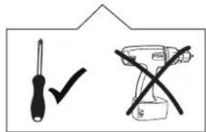
Tighten the screws with a hand screw driver only; do not use a battery-operated screw driver.
4.3 Electrical connections (connected loads)
(Connected loads and model designation: see front of the operating instructions)
This appliance may only be connected to the electricity supply by an approved electrician who must ensure that the installation complies with the statutory regulations (Germany VDE, Austria ÖVE, Switzerland SEV, etc.). The electrician must ensure that these regulations and those laid down by the local electricity supply company are observed.
When connecting the electrical appliance, install an all-pole disconnecting device with a contact gap of at least 3 mm. Make sure that the local mains voltage is the same as the voltage on the rating label.
To connect the appliance, unscrew the switchbox cover on the underside of the appliance to access the terminal block. After connecting the appliance, replace the cover and secure the connection cable with the strain relief clamp.
The connection cable must be at least H05 VVF.
If the excess cable of this appliance is damaged, it has to be replaced by the manufacturer, the Customer service of the manufacturer or by another qualified person to avoid danger.
Make sure that the excess cable length is not laid in the hob's installation area. See fig. 4 for the position of the cable cut-out.
Ensure that all live connections are safely insulated when installing the oven.
Electrical connections
| 400-415 V 3N~ 5 × 1.5 mm² | 400-415 V 2N~ 4 × 1.5 mm² | 230-240 V 1~ GKST 90 D - 3×4 mm² GKST 85.. - 3×2.5 mm² |
4.4 Maintenance and repair work
Always disconnect the appliance from the mains before carrying out repairs, this means the cut-out device must be opened. If you have to contact our service department, always quote the type and make numbers. You can find these numbers on the rating label or on page 1 of the Operating Instructions. Each time the glass ceramic hob is removed from the worktop, check the seals and replace if necessary.
Type: FGKST 85 ..
Facette
Fig. 1 Fig. 2

① Minimum distances to adjacent walls ② Cut-out dimension ③ Outside dimensions of recess ④ Cable access through the rear panel
Fig. 3 Fig. 4

Type: FGKST 85 .. FB
Fig. 1 Fig. 2

① Minimum distances to adjacent walls
② Inner cut-out dimension
③ Outer cut-out dimension
④ Outside dimensions of recess
⑤ Cable access through the rear panel
Fig. 3 Fig. 4

Type: GKST 90 D Fastening in worktops
Fig. 1 Fig. 2
Fig. 3
① Minimum distance to adjacent walls ② Cut-out dimension ③ Outside dimensions of recess ④ Cable routing in rear wall


4.2 Assembly




4. Assembly
4.2 Assembly


E
4.2 Assembly

E


4. Assembly
4.2 Installation

Model: GKST 90 D
Fig. 1 Fig. 2
Fig. 3


GR
4.2 Wall mounting
Fig.
Type: GKST 90 D
Fig. 1 . 2

Fig. 3
Fig. 4 . 3a


4. Assembly
4.2 Assembly




4. Installation
4.2 Installation
- Figure


- INSTALLATION
- CONTENTS
- OPERATIONS
- THINGS TO WATCH OUT FOR
- CLEANING AND MAINTENANCE
- FITTING
- SAFETY INSTRUCTIONS
- ATTENTION
- INSTRUCTIONS ON ENVIRONMENTAL PROTECTION
- DISPOSAL
- YOUR NEW HOB WITH TOUCH-CONTROL OPERATION
- TOUCH-CONTROL PANEL
- TOUCH-CONTROL OPERATIONS
- PARBOILING BOOST
- TWO-CIRCUIT / THREE-CIRCUIT CONNECTION
- TIMER
- LOCKING
- THE FOLLOWING KEYS CAN STILL BE USED
- RESIDUAL HEAT DISPLAY
- SAFETY SWITCH-OFF
- NOTES ON THE RIGHT TYPES OF SAUCEPANS
- IMPORTANT
- LIGHT AMOUNTS OF DIRT
- HEAVY DIRT
- CHANGES TO THE COLOUR OF THE CERAMIC SURFACE
- WORKTOP CUT-OUT
- ELECTRICAL CONNECTIONS (CONNECTED LOADS)
- ELECTRICAL CONNECTIONS
- MAINTENANCE AND REPAIR WORK
- ASSEMBLY
- E
- GR
- WALL MOUNTING
Brand : TEKA
Model : TR 90 DX
Category : Cooker