
TE-ID 1050/1 CE - Drill EINHELL - Free user manual and instructions
Find the device manual for free TE-ID 1050/1 CE EINHELL in PDF.


| Product type | Hammer drill |
| Brand | Einhell |
| Model | TE-ID 1050/1 CE |
| Rated voltage | 230 V ~ 50 Hz |
| Power input | 1050 W |
| No-load speed | 0 – 3000 rpm |
| Chuck capacity | 1.5 – 13 mm |
| Hammer function | Yes, adjustable |
| Drilling capacity – Concrete | 16 mm |
| Drilling capacity – Steel | 13 mm |
| Drilling capacity – Wood | 40 mm |
| Weight | 2.3 kg (approx.) |
| Cable length | 2 m |
| Protection class | Class II (double insulation) |
| Sound pressure level (LpA) | 89 dB(A) |
| Sound power level (LwA) | 100 dB(A) |
| Vibrations (metal drilling) | < 3.0 m/s² |
| Chuck type | Keyed chuck |
| Reversing switch | Yes |
| Variable speed | Yes (wheel) |
| Included accessories | Chuck key, depth stop, auxiliary handle |
| Recommended maintenance | Clean with a dry cloth, check brushes every 100 hours of use |
| Repairability | Spare parts available: brushes, switch, chuck, etc. |
Frequently Asked Questions - TE-ID 1050/1 CE EINHELL
User questions about TE-ID 1050/1 CE EINHELL
0 question about this device. Answer the ones you know or ask your own.
Ask a new question about this device
Download the instructions for your Drill in PDF format for free! Find your manual TE-ID 1050/1 CE - EINHELL and take your electronic device back in hand. On this page are published all the documents necessary for the use of your device. TE-ID 1050/1 CE by EINHELL.
USER MANUAL TE-ID 1050/1 CE EINHELL
GB Original operating instructions Impact Drill
natural_image
Close-up of a drill bit with a 8-pin drill bit and mechanical components (no text or symbols visible)-2-


natural_image
Close-up of a drill bit being inserted into a mechanical component, showing tool and shaft alignment (no text or symbols)

-3-
D

Schlagbohren in Beton (Handgriff)
Schlagbohren in Beton (Zusatzhandgriff)
Bohren in Metall (Handgriff)
Bohren in Metall (Zusatzhandgriff)
Schwingungsemissionswert a_n,D=2,217 m/s^2
Danger! Read the operating instructions to reduce the risk of inquiry

Caution! Wear ear-muffs. The impact of noise can cause damage to hearing.

Caution! Wear a breathing mask. Dust which is injurious to health can be generated when working on wood and other materials. Never use the device to work on any materials containing asbestos!

Caution! Wear safety goggles. Sparks generated during working or splinters, chips and dust emitted by the device can cause loss of sight.

To avoid damaging the gearbox, the drill / hammer drill selector switch should only be moved when the machine is at a standstill

Change the gear only when the drill is at a standstill. If you fail to observe this point, the gearing may be damaged.

Protection class II
GB
Danger!
When using equipment, a few safety precautions must be observed to avoid injuries and damage. Please read the complete operating manual with due care. Keep this manual in a safe place, so that the information is available at all times. If you give the equipment to any other person, give them these operating instructions as well. We accept no liability for damage or accidents which arise due to non-observance of these instructions and the safety information.
1. Safety regulations
The corresponding safety information can be found in the enclosed booklet.
Danger!
Read all safety regulations and instructions.
Any errors made in following the safety regulations and instructions may result in an electric shock, fire and/or serious injury.
Keep all safety regulations and instructions in a safe place for future use.
2. Layout and items supplied
2.1 Layout (Fig. 1a/1b)
- Drill chuck
- Drill depth stop
- Drill/hammer drill selector switch
- Locking button
- ON/OFF switch
- Speed controller
- Clockwise/Counter-clockwise switch
- Additional handle
- Gear selector switch
2.2 Items supplied
Please check that the article is complete as specified in the scope of delivery. If parts are missing, please contact our service center or the sales outlet where you made your purchase at the latest within 5 working days after purchasing the product and upon presentation of a valid bill of purchase. Also, refer to the warranty table in the service information at the end of the operating instructions.
- Open the packaging and take out the equipment with care.
-
Remove the packaging material and any packaging and/or transportation braces (if available).
-
Check to see if all items are supplied.
- Inspect the equipment and accessories for transport damage.
- If possible, please keep the packaging until the end of the guarantee period.
Danger!
The equipment and packaging material are not toys. Do not let children play with plastic bags, foils or small parts. There is a danger of swallowing or suffocating!
- Hammerdrill
- Drill depth stop
• Original operating instructions
• Safety instructions
3. Proper use
The drill is designed for drilling holes into wood, iron, non-ferrous metals and rock using the appropriate bits.
The equipment is to be used only for its prescribed purpose. Any other use is deemed to be a case of misuse. The user / operator and not the manufacturer will be liable for any damage or injuries of any kind caused as a result of this.
Please note that our equipment has not been designed for use in commercial, trade or industrial applications. Our warranty will be voided if the machine is used in commercial, trade or industrial businesses or for equivalent purposes.
4. Technical data
Mains voltage: 230 V \~ 50 Hz
Powerinput: 1050W
Idling speed 1: 0-1000 min ^1
Idling speed 2:0-2800 min ^1
Drilling capacity ...... Concrete 16 mm
Steel 13 mm
Wood 40 mm
Protection class:....II /回
Weight: 3,0kg
Sound and vibration
Sound and vibration values were measured in accordance with EN 60745.
GB
L_pA sound pressure level 97,58 dB(A)
K_nA^pH uncertainty 3 dB
L_pA sound pressure level 108,58 dB(A)
K_pA^pA uncertainty 3 dB
Danger!
Wear ear-muff s.
The impact of noise can cause damage to hearing.
Total vibration values (vector sum of three directions) determined in accordance with EN 60745.
Hammer drilling in concrete (handle)
Vibration emission value a_b,10=13,799 m/s^2
K uncertainty = 1,5 m/s²
Hammer drilling in concrete (additional handle)
Vibration emission value a_b,ID=8,580 m/s^2
Drilling in metal (handle)
Vibration emission value a_HJD = 4,281 ~m / s^2
K uncertainty = 1,5 m/s²
Drilling in metal (additional handle)
Vibration emission value a_n,ID = 2,217 m/s^2
K uncertainty = 1,5 m/s²
Additional information for electric power tools
The specified vibration value was established in accordance with a standardized testing method. It may change according to how the electric equipment is used and may exceed the specified value in exceptional circumstances.
The specified vibration value can be used to compare the equipment with other electric power tools.
The specified vibration value can be used for initial assessment of a harmful effect.
Keep the noise emissions and vibrations to a minimum.
• Only use appliances which are in perfect working order.
• Service and clean the appliance regularly.
• Adapt your working style to suit the appliance.
• Do not overload the appliance.
- Have the appliance serviced whenever necessary.
- Switch the appliance off when it is not in use.
• Wear protective gloves.
Caution! Residual risks
Even if you use this electric power tool in accordance with instructions, certain residual risks cannot be rules out. The following hazards may arise in connection with the equipment's construction and layout:
- Lung damage if no suitable protective dust mask is used.
- Damage to hearing if no suitable ear protection is used.
- Health damage caused by hand-arm vibrations if the equipment is used over a prolonged period or is not properly guided and maintained.
Warning! The electric power tool generates an electromagnetic fi eld during operation. Under certain circumstances this fi eld may actively or passively impede medical implants. To reduce the risk of serious or fatal injuries, we recommend persons with medical implants to consult their doctor and the manufacturer of the medical implant prior to using the equipment.
GB
5. Before starting the equipment
Before you connect the equipment to the mains supply make sure that the data on the rating plate are identical to the mains data.
Warning! Always pull the power plug before making adjustments to the equipment.
5.1. Fitting the additional handle (Fig. 2-3/Item 8)
The additional handle (8) enables you to achieve better stability whilst using the hammer drill. Do not use the tool without the additional handle.
The additional handle (8) is secured to the hammer drill by a clamp. During the handle clockwise tightens this clamp. Turning it anti-clockwise will release the clamp.
- The supplied additional handle (8) must first be fitted. To do this, the clamp must be opened by turning the handle until it is wide enough for the additional handle to be slid over the chuck (1) and on to the hammer drill.
- After you have positioned the additional handle (8), turn it to the most comfortable working position for you.
- Now turn the handle in the opposite direction again until the additional handle is secure.
- The additional handle (8) is suitable for both left-handed and right-handed users.
5.2 Fitting and adjusting the depth stop (Fig. 4/Item 2)
- Undo the thumb screw (a) on the additional handle (8) and insert the depth stop (2) in the hole of the additional handle.
- Set the depth stop and retighten the thumb screw.
- Now drill the hole until the depth stop touches the workpiece.
5.3 Fitting the drill bit (Fig. 5)
Always pull the power plug before making adjustments to the equipment.
- Release the depth stop as described in 5.2 and push it towards the additional handle. This provides free access to the chuck (1).
- This hammer drill is fitted with a keyless chuck (1).
- Open the chuck (1). The drill bit opening must be large enough to fit the drill bit into.
- Select a suitable drill bit. Push the drill bit as far as possible into the chuck opening.
- Close the chuck (1). Check that the drill bit is secure in the chuck (1).
- Check at regular intervals that the drill bit or tool is secure (pull the mains plug).
6. Operation
6.1 ON/OFF switch (Fig. 6/Item 5)
- First fit a suitable drill bit into the tool (see 5.3).
- Connect the mains plug to a suitable socket.
- Position the drill in the position you wish to drill.
To switch on:
Press the ON/OFF switch (5)
Continuous operation:
Secure the ON/OFF switch (5) with the locking button (4).
To switch off :
Press the ON/OFF switch (5) briefl y.
6.2 Adjusting the speed (Fig. 6/Item 5)
You can infinitely vary the speed whilst using the tool.
- Select the speed by applying a greater or lesser pressure to the ON/OFF switch (5).
- Select the correct speed: The most suitable speed depends on the workpiece, the type of use and the drill bit used.
- Low pressure on the ON/OFF switch (5): Lower speed (suitable for: small screws and soft materials)
- Greater pressure on the ON/OFF switch (5): Higher speed (suitable for large/long screws and hard materials)
Tip: Start drilling holes at low speed. Then increase the speed in stages.
Benefits:
- The drill bit is easier to control when starting the hole and will not slide away.
- You avoid drilling messy holes (for example in tiles).
6.3 Preselecting the speed (Fig. 7/Item 6)
The speed controller (6) enables you to define the maximum speed.
- Set the speed controller (6) to the required position.
- With the On/Off switch (5) pressed right in, the motor will now run as quickly as was set
GB
at the speed controller (6).
- The setting can also be made during operation.
Constant electronics
This tool is equipped with constant electronics. With constant electronics, the set speed is kept constant even when the tool is working under load.
6.4 Clockwise/Counter-clockwise switch (Fig. 6/Item 7)
- Change switch position only when the drill is at a standstill!
- Switch the direction of the hammer drill using the clockwise/counter-clockwise switch (7):
Direction Switch position
Clockwise (forwards and drill) Pushed in to the right
Counter-clockwise (reverse) Pushed in to the left
6.5 Drill / hammer drill selector switch (Fig. 7/Item 3)
- Change switch position only when the drill is at a standstill!
Drill:
Drill / hammer drill selector switch (3) in the drill position. (Position A) Use for: Wood, metal, plastic
Hammer drill
Drill / hammer drill selector switch (3) in the hammer drill position. (Position B) Use for: Concrete, rock, masonry
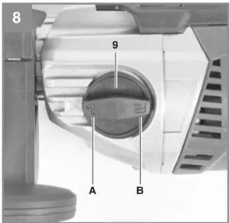
6.6 Defining the speed range (Fig. 8)
The speed selector switch (9) enables you to work within a specific speed range.
Switch position, setting 1 (A)
Speed range: High torque, low speed
Switch position, setting 2 (B)
Speed range: Low torque, high speed
Important. Do not attempt to make this setting whilst the drill is in use.
6.7 Tips for working with your hammer drill
6.7.1 Drilling concrete and masonry
- Switch the Drill/Hammer drill selector switch (3) to position B (Hammer drill).
• Always use carbide drill bits and a high speed setting for drilling into masonry and concrete.
6.7.2 Drilling steel
Switch the drill / hammer drill selector switch (3) to position A (drill).
- Always use HSS drill bits (HSS = high speed steel) and a low speed setting for drilling steel.
• We recommend that you lubricate the hole with a suitable cutting fluid to prevent unnecessary drill bit wear
6.7.3 Starting holes
If you wish to drill a deep hole in a hard material (such as steel), we recommend that you start the hole with a smaller drill bit.
6.7.4 Drilling tiles
• To start the hole, switch the drill / hammer drill selector switch (3) to position A (drill).
- Switch the drill / hammer drill selector switch (3) to position B (hammer drill) as soon as the drill bit has passed through the tiles.
7. Replacing the power cable
Danger!
If the power cable for this equipment is damaged, it must be replaced by the manufacturer or its after-sales service or similarly trained personnel to avoid danger.
GB
8. Cleaning, maintenance and ordering of spare parts
Danger!
Always pull out the mains power plug before starting any cleaning work.
8.1 Cleaning
- Keep all safety devices, air vents and the motor housing free of dirt and dust as far as possible. Wipe the equipment with a clean cloth or blow it with compressed air at low pressure.
- We recommend that you clean the device immediately each time you have finished using it.
- Clean the equipment regularly with a moist cloth and some soft soap. Do not use cleaning agents or solvents; these could attack the plastic parts of the equipment.
- Ensure that no water can seep into the device.
8.2 Carbon brushes
In case of excessive sparking, have the carbon brushes checked only by a qualified electrician. Important! The carbon brushes should not be replaced by anyone but a qualified electrician.
8.3 Maintenance
There are no parts inside the equipment which require additional maintenance.
8.4 Ordering replacement parts:
Please quote the following data when ordering replacement parts:
- Typeofmachine
• Article number of the machine
• Identification number of the machine - Replacement part number of the part required For our latest prices and information please go to www.isc-gmbh.info
9. Disposal and recycling
The unit is supplied in packaging to prevent its being damaged in transit. This packaging is raw material and can therefore be reused or can be returned to the raw material system.
The unit and its accessories are made of various types of material, such as metal and plastic. Defective components must be disposed of as special waste. Ask your dealer or your local council.
10. Storage
Store the equipment and accessories out of children's reach in a dark and dry place at above freezing temperature. The ideal storage temperature is between 5 and 30^ . Store the electric tool in its original packaging.
GB

For EU countries only
Never place any electric power tools in your household refuse.
To comply with European Directive 2012/19/EC concerning old electric and electronic equipment and its implementation in national laws, old electric power tools have to be separated from other waste and disposed of in an environment-friendly fashion, e.g. by taking to a recycling depot.
Recycling alternative to the return request:
As an alternative to returning the equipment to the manufacturer, the owner of the electrical equipment must make sure that the equipment is properly disposed of if he no longer wants to keep the equipment. The old equipment can be returned to a suitable collection point that will dispose of the equipment in accordance with the national recycling and waste disposal regulations. This does not apply to any accessories or aids without electrical components supplied with the old equipment.
The reprinting or reproduction by any other means, in whole or in part, of documentation and papers accompanying products is permitted only with the express consent of the iSC GmbH.
Subject to technical changes
GB
Service information
We have competent service partners in all countries named on the guarantee certificate whose contact details can also be found on the guarantee certificate. These partners will help you with all service requests such as repairs, spare and wearing part orders or the purchase of consumables.
Please note that the following parts of this product are subject to normal or natural wear and that the following parts are therefore also required for use as consumables.
| Category Example | |
| Wear parts* Carbon brushes, chuck | |
| Consumables* Drill bits | |
| Missing parts |
* Not necessarily included in the scope of delivery!
In the effect of defects or faults, please register the problem on the internet at www.isc-gmbh.info. Please ensure that you provide a precise description of the problem and answer the following questions in all cases:
• Did the equipment work at all or was it defective from the beginning?
• Did you notice anything (symptom or defect) prior to the failure?
• What malfunction does the equipment have in your opinion (main symptom)?
Describe this malfunction.
GB
Warranty certifi cate
Dear Customer,
All of our products undergo strict quality checks to ensure that they reach you in perfect condition. In the unlikely event that your device develops a fault, please contact our service department at the address shown on this guarantee card. You can also contact us by telephone using the service number shown. Please note the following terms under which guarantee claims can be made:
- These guarantee terms apply to consumers only, i.e. natural persons intending to use this product neither for their commercial activities nor for any other self-employed activities. These warranty terms regulate additional warranty services, which the manufacturer mentioned below promises to buyers of its new products in addition to their statutory rights of guarantee. Your statutory guarantee claims are not affected by this guarantee. Our guarantee is free of charge to you.
- The warranty services cover only defects due to material or manufacturing faults on a product which you have bought from the manufacturer mentioned below and are limited to either the rectification of said defects on the product or the replacement of the product, whichever we prefer. Please note that our devices are not designed for use in commercial, trade or professional applications. A guarantee contract will not be created if the device has been used by commercial, trade or industrial business or has been exposed to similar stresses during the guarantee period.
-
The following are not covered by our guarantee:
-
Damage to the device caused by a failure to follow the assembly instructions or due to incorrect installation, a failure to follow the operating instructions (for example connecting it to an incorrect mains voltage or current type) or a failure to follow the maintenance and safety instructions or by exposing the device to abnormal environmental conditions or by lack of care and maintenance.
- Damage to the device caused by abuse or incorrect use (for example overloading the device or the use or unapproved tools or accessories), ingress of foreign bodies into the device (such as sand, stones or dust, transport damage), the use of force or damage caused by external forces (for example by dropping it).
-
Damage to the device or parts of the device caused by normal or natural wear or tear or by normal use of the device.
-
The guarantee is valid for a period of 24 months starting from the purchase date of the device. Guarantee claims should be submitted before the end of the guarantee period within two weeks of the defect being noticed. No guarantee claims will be accepted after the end of the guarantee period. The original guarantee period remains applicable to the device even if repairs are carried out or parts are replaced. In such cases, the work performed or parts fitted will not result in an extension of the guarantee period, and no new guarantee will become active for the work performed or parts fitted. This also applies if an on-site service is used.
-
To make a claim under the guarantee, please register the defective device at: www.isc-gmbh.info. Please keep your bill of purchase or other proof of purchase for the new device. Devices that are returned without proof of purchase or without a rating plate shall not be covered by the guarantee, because appropriate identification will not be possible. If the defect is covered by our guarantee, then the item in question will either be repaired immediately and returned to you or we will send you a new replacement.
Of course, we are also happy offer a chargeable repair service for any defects which are not covered by the scope of this guarantee or for units which are no longer covered. To take advantage of this service, please send the device to our service address.
Also refer to the restrictions of this warranty concerning wear parts, consumables and missing parts as set out in the service information in these operating instructions.
F

Subject to change without notice
Archive-File/Record: NAPR014834
Documents registrar: Georg Riedel
Wiesenweg 22, D-94405 Landau/Isar

EH 11/2016 (01)
- Schlagbohren in Beton (Handgriff)
- Schlagbohren in Beton (Zusatzhandgriff)
- Bohren in Metall (Handgriff)
- Bohren in Metall (Zusatzhandgriff)
- GB
- Danger!
- Safety regulations
- Layout and items supplied
- Layout (Fig. 1a/1b)
- Items supplied
- Proper use
- Technical data
- Sound and vibration
- Wear ear-muff s.
- Hammer drilling in concrete (handle)
- Hammer drilling in concrete (additional handle)
- Drilling in metal (handle)
- Drilling in metal (additional handle)
- Additional information for electric power tools
- Keep the noise emissions and vibrations to a minimum.
- Caution! Residual risks
- Even if you use this electric power tool in accordance with instructions, certain residual risks cannot be rules out. The following hazards may arise in connection with the equipment's construction and layout:
- Before starting the equipment
- Fitting the additional handle (Fig. 2-3/Item 8)
- Fitting and adjusting the depth stop (Fig. 4/Item 2)
- Fitting the drill bit (Fig. 5)
- Operation
- ON/OFF switch (Fig. 6/Item 5)
- To switch on:
- Continuous operation:
- To switch off :
- Adjusting the speed (Fig. 6/Item 5)
- Benefits:
- Preselecting the speed (Fig. 7/Item 6)
- Clockwise/Counter-clockwise switch (Fig. 6/Item 7)
- Direction Switch position
- Drill / hammer drill selector switch (Fig. 7/Item 3)
- Drill:
- Hammer drill
- Defining the speed range (Fig. 8)
- Switch position, setting 1 (A)
- Switch position, setting 2 (B)
- Tips for working with your hammer drill
- Drilling concrete and masonry
- Drilling steel
- Starting holes
- Drilling tiles
- Replacing the power cable
- Cleaning, maintenance and ordering of spare parts
- Cleaning
- Carbon brushes
- Maintenance
- Ordering replacement parts:
- Disposal and recycling
- Storage
- Service information
- Warranty certifi cate
- F
Brand : EINHELL
Model : TE-ID 1050/1 CE
Category : Drill