
RG-ES 1433 - Lawn mower EINHELL - Free user manual and instructions
Find the device manual for free RG-ES 1433 EINHELL in PDF.


| Product Type | Electric Lawn Mower |
| Brand | Einhell |
| Model | RG-ES 1433 |
| Motor Power | 1,400 W |
| Cutting Width | 33 cm |
| Cutting Height | 25-75 mm, centrally adjustable |
| Grass Catcher Type | Rigid grass catcher with fill indicator |
| Grass Catcher Capacity | 30 L |
| Handle | Folding handle, height adjustable |
| Weight | Approx. 10 kg |
| Power Supply | Electric with cable (length not specified) |
| Blade Type | Rotary blade made of hardened steel |
| Motor Speed | 3,400 rpm |
| Sound Level (LwA) | ~ 88 dB(A) |
| Vibration | ~ 5.0 m/s² |
| Main Functions | Cutting, mulching (option), grass collection |
| Maintenance and Cleaning | Regular cleaning of the grass catcher and blade, greasing of bearings |
| Safety | Two-hand safety switch, engine stops when released |
| Spare Parts and Repairability | Blade, grass catcher, wheels available via Einhell after-sales service |
| General Information | Recommended use for medium-sized lawns |
Frequently Asked Questions - RG-ES 1433 EINHELL
User questions about RG-ES 1433 EINHELL
0 question about this device. Answer the ones you know or ask your own.
Ask a new question about this device
Download the instructions for your Lawn mower in PDF format for free! Find your manual RG-ES 1433 - EINHELL and take your electronic device back in hand. On this page are published all the documents necessary for the use of your device. RG-ES 1433 by EINHELL.
USER MANUAL RG-ES 1433 EINHELL
3


natural_image
Mechanical setup with two vertical rods and a cylindrical roller, labeled with dimension '1' (no text or symbols on the components)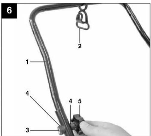

4
natural_image
Close-up of a metallic hook-shaped object with a curved handle, no text or symbols visible
natural_image
Close-up of a mechanical linkage with labeled points A and 9 (no text or symbols beyond labels)
natural_image
Illustration of hands holding a tool interacting with a wire fence, showing motion arrows (no text or symbols)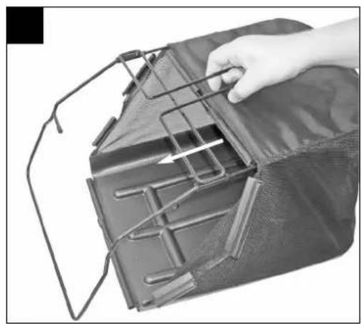
natural_image
Close-up of a hand placing a metal bracket into a dark plastic container with internal structure (no text or symbols visible)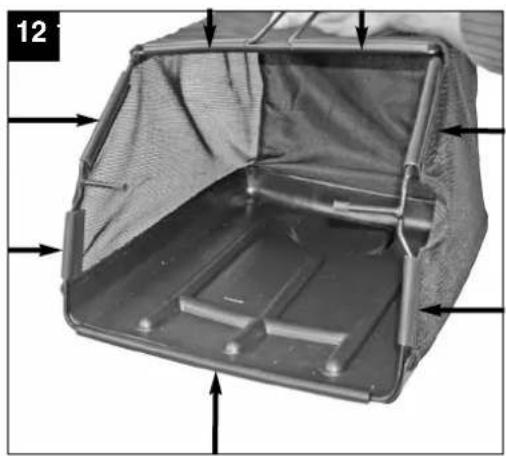
natural_image
Interior view of a mechanical device with internal components and arrows indicating movement (no text or symbols)



natural_image
Black-and-white photo of a vacuum cleaner with attached arm and wheels (no text or symbols visible)
natural_image
Exterior view of a portable industrial machine with handle and wheels (no visible text or symbols)D
⚠️Achtung!
When using equipment, a few safety precautions must be observed to avoid injuries and damage. Please read the complete operating manual with due care. Keep this manual in a safe place, so that the information is available at all times. If you give the equipment to any other person, give them these operating instructions as well.
We accept no liability for damage or accidents which arise due to non-observance of these instructions and the safety information.
1. Safety regulations
The corresponding safety information can be found in the enclosed booklet.
CAUTION!
Read all safety regulations and instructions.
Any errors made in following the safety regulations and instructions may result in an electric shock, fire and/or serious injury.
Keep all safety regulations and instructions in a safe place for future use.
3. Description of the warning logos (see Fig. 3)
A = Important!
Read the directions for use before operating the tool.
B = Keep other persons (and animals) away from the danger zone.
C = Wear hearing and eye protection.
D = Sharp work tools - Do not cut your fingers or toes! Switch off the device and pull the power plug before engaging in any maintenance/cleaning work or if the cable is tangled or damaged. Keep the power cable away from the cutting unit.
2. Layout (Fig. 1/2)
- ON/OFF switch
- Safety lock-off
- Power cable
- Cable grip
- Top push bar
- Lower push bar
- Push bar bracket
- Scarifying depth
- Grass basket
- Ejector flap
- Frame parts for grass basket
-
Cable clips
-
Fastening screws for push bar
-
Fastening screws for wall mount
-
Wall mount
3. Proper use
The equipment is intended for private use i.e. for use in home and gardening environments.
Scarifiers for private use are machines whose annual operating time generally does not exceed 10 hours, during which the machine is primarily used to maintain small-scale, residential lawns and home/hobby gardens. Public facilities, sporting halls, and agricultural/forestry applications are excluded.
The operating instructions as supplied by the manufacturer must be kept and referred to in order to ensure that the equipment is properly used and maintained. The instructions contain valuable information on operating, maintenance and servicing conditions.
Important! Due to the high risk of bodily injury to the user, the equipment may not be used to grind up branch or hedge clippings. Moreover, the equipment may not be used as a power cultivator to level out high areas such as mole hills.
For safety reasons, the scarifier may not be used as a drive unit for other equipment or toolkits of any kind, unless specifically advised to do so by the manufacturer.
The equipment is to be used only for its prescribed purpose. Any other use is deemed to be a case of misuse. The user / operator and not the manufacturer will be liable for any damage or injuries of any kind caused as a result of this.
Please note that our equipment has not been designed for use in commercial, trade or industrial applications. Our warranty will be voided if the machine is used in commercial, trade or industrial businesses or for equivalent purposes.
GB
4. Technical data
Voltage: 230 V \~ 50 Hz
Power consumption: 1400 W
Working width: 33 cm
Number of blades 20 pieces
Scarifying depth: - 3 / 3 / 7 / 9 mm
L_pA sound pressure level: 78 dB(A)
L_WA sound power level: 99 dB(A)
K uncertainty 1,1 dB(A)
Vibration on the shaft a_hv 3.9 m/s ^2
K uncertainty 1,5 m/s
Total vibration values (vector sum of three directions) determined in accordance with EN 60335.
Warning!
The specified vibration value was established in accordance with a standardized testing method. It may change according to how the electric equipment is used and may exceed the specified value in exceptional circumstances.
The specified vibration value can be used to compare the equipment with other electric power tools.
The specified vibration value can be used for initial assessment of a harmful effect.
Keep the noise emissions and vibrations to a minimum.
●Only use appliances which are in perfect working order.
●Service and clean the appliance regularly.
●Adapt your working style to suit the appliance.
●Do not overload the appliance.
●Have the appliance serviced whenever necessary.
●Switch the appliance off when it is not in use.
●Wear protective gloves.
5. Before starting the equipment
The scarifier is delivered unassembled. The grass basket and the complete push bar must be assembled and mounted before using the scarifier. Follow the operating instructions step-by-step and use the pictures provided as a visual guide to easily assemble the machine.
Fitting the push bar brackets (see Figs. 4 and 5)
- Remove the star screw (Fig. 4/Item 1) and the pressure plate (Fig. 4/Item 2)
- Connect the push bar bracket (Fig. 4/Item 3) to the fastening screw. Ensure that the curve in the tube (Fig. 5/Item 1) is facing outside.
- Now remount the pressure plate and tighten with the star screw. Important. The identical tilt angle must be set for both push bar brackets.
Fitting the lower push bar (see Fig. 6)
- Slide the lower push bar (Fig. 6/Item 1) over the push bar brackets.
Do not forget to slide the stress-relief clip (Fig. 6/Item 2) onto the tube beforehand.
●Now screw the tubes together using the screws supplied (Fig. 6/Item 3), the plastic sleeves (Fig. 6/Item 4) and the star screw (Fig. 6/Item 5).
Fitting the upper push bar (see Fig. 7)
●Position the upper push bar (Fig. 7) such that its holes line up with the holes of the lower bar.
●Now screw the tubes together using the screws supplied (Fig. 7/Item 1), the plastic sleeves (Fig. 7/Item 2) and the star screw (Fig. 7/Item 3).
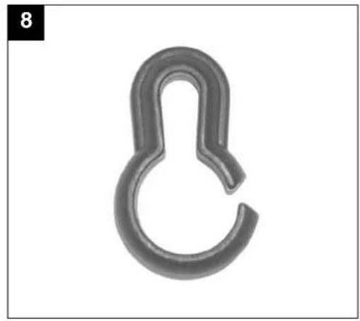
●Using the cable clips supplied (Fig. 8), attach the power cable to the tubes of the push bars so that it is possible to open and shut the ejector flap (Fig. 9/Item A).
●Important!
Please ensure that the ejector flap can be opened and closed easily!
Assembling the grass basket (see Figs. 10 and -13)
●Push both frame parts into each other (Fig. 10).
●Pull the grass basket over the metal frame (Fig. 11).
●Pull the rubber clips over the metal frame (Fig. 12).
●To hang the grass basket on the scarifier you must lift the ejector flap (Fig. 13/Item 1) with one hand and with the other hand take hold of the grass bag by the handle and hook it onto the scarifier from above (Fig. 13).
GB
Important!
Before you ever hook the grass basket to the scarifier you must ensure that the motor is switched off and the cutting unit is not rotating.
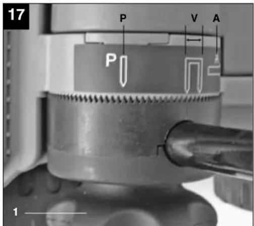
Adjusting the handlebar height (see Fig. 17)
Loosen the star screw (Fig. 17/Item 1) on both sides of the scarifier by turning several revolutions. Now adjust the handlebar to the desired height.
Important!
The height of the handlebar may be adjusted within the mark (Fig. 17/Item V) during operation. Retighten the star screws.
Important!
The identical tilt angle must be set on both sides.
Adjusting the scarifier depth (see Fig. 14)
The scarifier depth is adjusted at both front wheels via the adjustment mechanism. For this, pull out the adjusting screw and turn the wheel to the left or right into one of the available positions (0/I/II/III).
Important!
The scarifier depth must always be identically set on both sides!
0 = drive/transport position
I = scarifier depth 3 mm
II = scarifier depth 7 mm
III = scarifier depth 9 mm
Electrical connection
The equipment can be connected to any normal socket with 230V AC. It is only acceptable to connect it to a shockproof socket with a 16A circuit breaker. Furthermore, a residual-current-operated protective device with max. 30 mA should be connected upstream.
Power cable
Please only use power cables that are not damaged. The total length of the power cable should not exceed 50 meters; going beyond this distance will reduce the power output of the electric motor. The power cable must have a cross-section of 3 x 1.5 mm2. The insulating sheath of scarifier power cables is frequently damaged.
Some of the causes for this are:
●Cracking from running over the cable
● Pinching when the power cable is dragging under doors and pulled through windows
●Cracking due to old age of the insulation
●Kinking by improperly fastening or guiding the power cable
The power cables must, at the very minimum, be of type HO5RN-F and 3-stranded. The cable type must be printed somewhere on the power cable. Only purchase power cables that are marked as such! Plugs and socket couplers for the power cables must be made from rubber and be splash-proof. There is a limit to how long power cables can be. Longer power cables require larger conductor cross-sections. Power cables and connecting lines must be regularly checked for damage. Ensure that the lines are de-energized before checking them. Completely unwind the power cable. Also check power cable entry points, plugs and socket couplers for kinks.
6. Operation
Connect the machine's power supply cable to the plug (Fig. 15/Item 1) and secure the power cable with the stress-relief clip (Fig 15/Item 2).
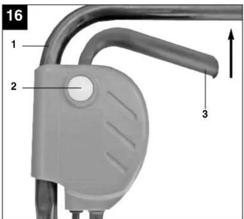
Important! To prevent accidental start-up of the equipment, the push-bar (Fig. 16 / Item 1) is equipped with a safety lock-off (Fig. 16 / Item 2) which must be pressed before the lever switch (Fig. 16 / Item 3) can be pressed. If the lever switch is released, the equipment switches off.
Repeat this process several times so that you are sure that the machine functions properly. Before you perform any repair or maintenance work on the machine, ensure that the cutting unit is not rotating and that the power supply is disconnected.
Important! Never open the ejector flap when the motor is running. A rotating cutting unit can cause injuries.
Always fasten the ejector flap carefully. The flap flips back to the "Closed" position by the tension springs! Always ensure that a safe distance (provided by the long handles) is maintained between the user and the housing. Be especially careful when scarifying and changing direction on slopes and inclines. Maintain a solid footing and wear sturdy, non-slip footwear and long trousers. Always scarify along the incline (not up and down).
For safety reasons, the scarifier may not be used to scarify inclines whose gradient exceeds 15 degrees. Use special caution when backing up and pulling the scarifier (tripping hazard)!
Tips for proper working
It is recommended that you overlap scarifying paths a little.
GB
Try to scarify in straight lines for a nice, clean look. Insodoing, the aeration swaths should always overlap each other by a few centimeters in order to avoid bare strips.
As soon as grass clippings start to trail the scarifier, it is time to empty the grass basket.
Important! Before taking off the grass basket, switch off the motor and wait until the roller has come to a stop.
To remove the grass basket, lift up the ejector flap with one hand, while unhooking the basket with the other.
How frequently you should scarify your lawn is determined primarily by the speed at which the grass grows and the hardness of the soil.
Keep the underside of the equipment clean and remove soil and grass build-up. Deposits make it more difficult to start the aerator and decrease the quality of the scarifying.
Always scarify along inclines (not up and down). Switch off the motor before doing any checks on the roller.
Important!
The roller rotates for a few seconds after the motor is switched off. Never attempt to stop the roller. In the event that the rotating roller strikes an object, immediately switch off the equipment and wait for the roller to come to a complete stop. Then inspect the condition of the roller. Replace any parts that are damaged (see section 8.4).
Lay the power cable on the ground in loops in front of the power outlet. Scarify away from the power outlet and cable, making sure that the power cable always trails in the already scarified grass so that the equipment does not travel over the cable.
7. Replacing the power cable
If the power cable for this equipment is damaged, it must be replaced by the manufacturer or its after-sales service or similarly trained personnel to avoid danger.
8. Cleaning, maintenance and ordering of spare parts
Always pull out the mains power plug before starting any cleaning work.
8.1 Cleaning
- Keep all safety devices, air vents and the motor housing free of dirt and dust as far as possible. Wipe the equipment with a clean cloth or blow it with compressed air at low pressure.
●We recommend that you clean the device immediately each time you have finished using it.
●Clean the equipment regularly with a moist cloth and some soft soap. Do not use cleaning agents or solvents; these could attack the plastic parts of the equipment. Ensure that no water can seep into the device.
8.2 Carbon brushes
In case of excessive sparking, have the carbon brushes checked only by a qualified electrician. Important! The carbon brushes should not be replaced by anyone but a qualified electrician.
8.3 Maintenance
●A worn out or damaged cutting unit should be replaced by an authorised expert (see adress on the warranty certificate).
●Take care that all fastening elements (screws, nuts, etc.) are firmly tightened, so that you can work safely with the scarifier.
●Store the scarifier in a dry place.
- For longer life, all screw-fastened parts, such as wheels and axles should be cleaned and subsequently oiled.
●Regular servicing of the scarifier not only secures longer endurance and performance, but also contributes to an accurate and simple scarification of your lawn.
- At the end of the season, carry out a general check of the scarifier, and remove all residue collected. Before the start of every season, it is absolutely necessary to check the state of the scarifier. Contact our Customer Service (see address on the warranty certificate) if repair work is necessary.
To save storage space, the push bar has a P and an A position. (Fig. 17).
●In the P-position, the scarifier can be stored in a corner, to save space (Fig. 18).
●In the A-position, the scarifier can be hung (as shown in Fig 19) on the wall mount included, to save space.
8.4 Replacing the spike drum
For safety reasons, we recommend having the spike drum replaced by an authorized professional (see address on warranty certificate).
Important!
Wear work gloves!
Only replace the unit with a genuine Einhell spike drum, as this will ensure top performance and safety under all conditions.
8.5 Ordering replacement parts:
Please quote the following data when ordering replacement parts:
●Type of machine
●Article number of the machine
●Identification number of the machine
●Replacement part number of the part required
For our latest prices and information please go to www.isc-gmbh.info
Replacement cutting unit Art. No.: 34.211.08
9. Disposal and recycling
The unit is supplied in packaging to prevent its being damaged in transit. This packaging is raw material and can therefore be reused or can be returned to the raw material system.
The unit and its accessories are made of various types of material, such as metal and plastic. Defective components must be disposed of as special waste. Ask your dealer or your local council.
GB
10. Troubleshooting guide
| Fault | Possible causes | Rectification |
| Motor does not start a) No electricity in plugb) Cable defectivec) Switch, switch/plug block defectived) Connections to motor or capacitor disconnectede) Housing clogged | a) Check line and fuseb) Checkc) Have machine checked by a customer service centerd) Have machine checked by a customer service centere) If necessary adjust working depth. Clean housing so that the roller can run freely | |
| Engine performance drops a) Soil is too firmb) Housing cloggedc) Roller badly worn | a) Change working depthb) Clean housingc) Replace roller | |
| Imprecise scarifying result a) roller wornb) Wrong working depth | a) Replace rollerb) Correct working depth | |
| Motor is running, roller is not rotating | a) Toothed belt is torn a) By customer service workshop |
Important notice! To protect the motor itis equipped with a thermal overload switch which cuts out when overloaded and starts again automatically after a short cooling-down period.
F
Attention!
① explains the following conformity according to EU directives and norms for the following product
Notified Body: Notified Body No.: Reg. No.:
2000/14/EC_2005/88/EC
x Annex V
Annex VI
Noise: measured L_WA = 98 dB (A); guaranteed L_WA = 99 dB (A) P = KW; L/∅ = cm Notified Body:
2004/26/EC
Emission No.
Standard references:
EN 60335-1; EN 60335-2-92; EN 13684; EN 62233;
EN 55014-1; EN 55014-2; EN 61000-3-2; EN 61000-3-3
First CE: 08 Archive-File/Record: 3420477-13-4175500-10
Art.-No.: 34.204.78 I.-No.: 11020
Subject to change without notice Wiesenweg 22, D-94405 Landau/Isar
Documents registrar: Scheifl Alexander

natural_image
Symbol of a trash bin crossed out by two diagonal lines (no text or numbers present)
©Nur für EU-Länder
For EU countries only
Never place any electric tools in your household refuse.
To comply with European Directive 2002/96/EC concerning old electric and electronic equipment and its implementation in national laws, old electric tools have to be separated from other waste and disposed of in an environment-friendly fashion, e.g. by taking to a recycling depot.
Recycling alternative to the demand to return electrical devices:
As an alternative to returning the electrical device, the owner is obliged to cooperate in ensuring that the device is properly recycled if ownership is relinquished. This can also be done by handing over the used device to a returns center, which will dispose of it in accordance with national commercial and industrial waste management legislation. This does not apply to the accessories and auxiliary equipment without any electrical components which are included with the used device.
The reprinting or reproduction by any other means, in whole or in part, of documentation and papers accompanying products is permitted only with the express consent of ISC GmbH.
F
All of our products undergo strict quality checks to ensure that they reach you in perfect condition. In the unlikely event that your device develops a fault, please contact our service department at the address shown on this guarantee card. Of course, if you would prefer to call us then we are also happy to offer our assistance under the service number printed below. Please note the following terms under which guarantee claims can be made:
- These guarantee terms cover additional guarantee rights and do not affect your statutory warranty rights. We do not charge you for this guarantee.
- Our guarantee only covers problems caused by material or manufacturing defects, and it is restricted to the rectification of these defects or replacement of the device. Please note that our devices have not been designed for use in commercial, trade or industrial applications. Consequently, the guarantee is invalidated if the equipment is used in commercial, trade or industrial applications or for other equivalent activities. The following are also excluded from our guarantee: compensation for transport damage, damage caused by failure to comply with the installation/assembly instructions or damage caused by unprofessional installation, failure to comply with the operating instructions (e.g. connection to the wrong mains voltage or current type), misuse or inappropriate use (such as overloading of the device or use of non-approved tools or accessories), failure to comply with the maintenance and safety regulations, ingress of foreign bodies into the device (e.g. sand, stones or dust), effects of force or external influences (e.g. damage caused by the device being dropped) and normal wear resulting from proper operation of the device.
The guarantee is rendered null and void if any attempt is made to tamper with the device.
-
The guarantee is valid for a period of 2 years starting from the purchase date of the device. Guarantee claims should be submitted before the end of the guarantee period within two weeks of the defect being noticed. No guarantee claims will be accepted after the end of the guarantee period. The original guarantee period remains applicable to the device even if repairs are carried out or parts are replaced. In such cases, the work performed or parts fitted will not result in an extension of the guarantee period, and no new guarantee will become active for the work performed or parts fitted. This also applies when an on-site service is used.
-
In order to assert your guarantee claim, please send your defective device postage-free to the address shown below. Please enclose either the original or a copy of your sales receipt or another dated proof of purchase. Please keep your sales receipt in a safe place, as it is your proof of purchase. It would help us if you could describe the nature of the problem in as much detail as possible. If the defect is covered by our guarantee then your device will either be repaired immediately and returned to you, or we will send you a new device.
Of course, we are also happy offer a chargeable repair service for any defects which are not covered by the scope of this guarantee or for units which are no longer covered. To take advantage of this service, please send the device to our service address.
F BULLETIN DE GARANTIE
Chère Cliente, Cher Client,




- D
- ⚠️Achtung!
- Safety regulations
- CAUTION!
- Read all safety regulations and instructions.
- Description of the warning logos (see Fig. 3)
- Layout (Fig. 1/2)
- Proper use
- GB
- Technical data
- Warning!
- Keep the noise emissions and vibrations to a minimum.
- Before starting the equipment
- Fitting the push bar brackets (see Figs. 4 and 5)
- Fitting the lower push bar (see Fig. 6)
- Fitting the upper push bar (see Fig. 7)
- ●Important!
- Assembling the grass basket (see Figs. 10 and -13)
- Important!
- Adjusting the handlebar height (see Fig. 17)
- Adjusting the scarifier depth (see Fig. 14)
- Electrical connection
- Power cable
- Operation
- Tips for proper working
- Important! Before taking off the grass basket, switch off the motor and wait until the roller has come to a stop.
- Replacing the power cable
- Cleaning, maintenance and ordering of spare parts
- Cleaning
- Carbon brushes
- Maintenance
- Replacing the spike drum
- Ordering replacement parts:
- Disposal and recycling
- Troubleshooting guide
- F
- Attention!
- ©Nur für EU-Länder
- For EU countries only
- F BULLETIN DE GARANTIE
- Chère Cliente, Cher Client,
Brand : EINHELL
Model : RG-ES 1433
Category : Lawn mower