
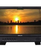
TM-H150CG - Monitor JVC - Free user manual and instructions
Find the device manual for free TM-H150CG JVC in PDF.


| Product Type | Color Video Monitor |
| Model | TM-H150CG |
| Brand | JVC |
| Display Technology | CRT |
| Screen Size | 15 inches (diagonal) |
| Input Signals | Composite Video (BNC), S-Video (4-pin), RGB (optional) |
| Resolution | 640 x 480 (approx) |
| Power Supply | AC 100-240V, 50/60Hz |
| Power Consumption | 60W (typical) |
| Dimensions (W x H x D) | 14.5 x 13.5 x 15.0 in (368 x 343 x 381 mm) |
| Weight | 18.5 lbs (8.4 kg) |
| Controls | Brightness, Contrast, Color, Tint, Sharpness |
| Cleaning | Wipe with soft dry cloth; avoid solvents |
| Safety | Do not open; refer to qualified service personnel |
| Spare Parts | Available through JVC authorized service centers |
Frequently Asked Questions - TM-H150CG JVC
User questions about TM-H150CG JVC
0 question about this device. Answer the ones you know or ask your own.
Ask a new question about this device
Download the instructions for your Monitor in PDF format for free! Find your manual TM-H150CG - JVC and take your electronic device back in hand. On this page are published all the documents necessary for the use of your device. TM-H150CG by JVC.
USER MANUAL TM-H150CG JVC
For Customer Use:
Enter below the Serial No, which is located on the rear of the cabinet.
Retain this information for future reference.
Thank you for purchasing this JVC color video monitor. Before using it, read and follow all instructions carefully to take full advantage of the monitor's capabilities.
SAFETY PRECAUTIONS
In order to prevent any fatal accidents caused by misoperation or mishandling the monitor, be fully aware of all the following precautions.
WARNINGS
To prevent fire or shock hazard, do not expose this monitor to rain or moisture. Dangerous high voltages are present inside the unit. Do not remove the back cover of the cabinet. When servicing the monitor, consult qualified service personnel. Never try to service it yourself.
WARNING: THIS APPARATUS MUST BE EARTHED.
Improper operations, in particular alteration of high voltage or changing the type of tube may result in x-ray emission of considerable dose. A unit altered in such a way no longer meets the standards of certification, and must therefore no longer be operated.
This monitor is equipped with a 3-blade grounding-type plug to satisfy FCC rule. If you are unable to insert the plug into the outlet, contact your electrician.
FCC INFORMATION (U.S.A. only)
CAUTION: Changes or modification not approved by JVC could void the user's authority to operate the equipment.
NOTE: This equipment has been tested and found to comply with the limits for a Class B digital device, pursuant to Part 15 of the FCC Rules. These limits are designed to provide reasonable protection against harmful interference in a residential installation. This equipment generates, uses and can radiate radio frequency energy and, if not installed and used in accordance with the instructions, may cause harmful interference to radio communications. However, there is no guarantee that interference will not occur in a particular installation. If this equipment does cause harmful interference to radio or television reception, which can be determined by turning the equipment off and on, the user is encouraged to try to correct the interference by one or more of the following measures:
– Reorient or relocate the receiving antenna. – Increase the separation between the equipment and receiver. – Connect the equipment into an outlet on a circuit different from that to which the receiver is connected. – Consult the dealer or an experienced radio/TV technician for help.
Notice (U.S.A. only)
This product utilizes both a Cathode Ray Tube (CRT) and other components that contain lead. Disposal of these materials may be regulated in your community due to environmental considerations. For disposal or recycling information please contact your local authorities, or the Electronics Industries Alliance: http://www.eiae.org .
PRECAUTIONS
- Use only the power source specified on the unit. (120 V AC/220 – 240 V AC, 50 Hz/60 Hz)
- When not using this unit for a long period of time, or when cleaning it, be sure to disconnect the power plug from the AC outlet.
- Do not allow anything to rest on the power cord. And do not place this unit where people will tread on the cord. Do not overload wall outlets or power cords as this can result in a fire or electric shock.
- Avoid using this unit under the following conditions: – in extremely hot, cold or humid places, – in dusty places,
- near appliances generating strong magnetic fields, – in places subject to direct sunlight, – in badly ventilated places, – in automobiles with doors closed.
- Do not cover the ventilation slots while in operation as this could obstruct the required ventilation flow.
- When dust accumulates on the screen surface, clean it with a soft cloth.
- Unplug this unit from the AC outlet and refer servicing to qualified service personnel under the following conditions:
- when the power cord is frayed or the plug is damaged,
- if liquid has been spilled into the unit,
- if the unit has been dropped or the cabinet has been damaged,
- when the unit exhibits a distinct change in performance.
- Do not attempt to service this unit yourself as opening or removing covers may expose you to dangerous voltage or other hazards. Always refer servicing to qualified service personnel.
- When replacement parts are required, have the service personnel verify in writing that the replacement parts he/she uses have the same safety characteristics as the original parts. Use of manufacture's specified replacement parts can prevent fire, shock, or other hazards.
- Upon completion of any servicing or repair work to this unit, please ask the service personnel to perform the safety check described in the manufacturer's service literature.
- When this unit reaches the end of its useful life, improper disposal could result in a picture tube implosion. Ask qualified service personnel to dispose of this unit.
POWER CONNECTION
The power supply voltage rating of this product is AC 120 V (For U.S.A. and Canada only) and AC 220 – 240 V (For European countries or United Kingdom), the power cord attached conforms to the following power supply voltage and countries. Use only the power cord designated to ensure Safety and EMC regulations of each countries.
Power cord

Power supply voltage : AC 120 V AC 220 – 240 V
Countries : U.S.A. and Canada

AC 220 - 240 V
European countries

United Kingdom
Warning:
- Do not use the same Power Cord for AC 120 V as for AC 220 – 240 V. Doing so may cause malfunction, electric shock or fire.
Note for the United Kingdom power cord only
The plug on the United Kingdom power cord has a built-in fuse. When replacing the fuse, be sure to use only a correctly rated approved type, re-fit the fuse cover.
(Consult your dealer or qualified service personnel.)
How to replace the fuse
Open the fuse compartment with the blade screw driver, and replace the fuse.
(* An example is shown in the illustration.)

SCREEN BURN
- It is not recommended to keep a certain still image displayed on screen for a long time as well as displaying extremely bright images on screen. This may cause a burning (sticking) phenomenon on the screen of cathode-ray tube. This problem does not occur as far as displaying normal video playback motion images.
■ Supplementary Explanation
= Information for monitor operation = This monitor uses a high precision CRT (cathode ray tube). Please follow the procedures below. * For stable operation of the CRT, approximately 30 minutes running time is required from the time the power is turned on. * When the monitor is installed, it can be easily affected by surrounding magnetic fields, which can generate irregular color on the screen. When it is difficult to eradicate, degauss from outside using a degausser, etc.
Contents
SAFETY PRECAUTIONS 2
Controls and Features .... 4
Front Panel 4
Rear Panel 6
Input Card (option) 7
Preparation 9
Installing the Input Card 9
Basic Menu Operations (MENU, SET-UP MENU).... 10
How to Use MENU 12
How to Use SET-UP MENU 13
How to Use the External Control.... 15
Troubleshooting 16
Specifications 18
Controls and Features
Front Panel

1 CHROMA ( :Chroma)/PHASE ( :Phase) button*
Press this button to activate the Chroma (picture color density) adjustment mode or the Phase (picture hue) adjustment mode. Each time you press the button, the adjustment modes change.
Chroma Phase
Adjust the value with the VOLUME/SELECT
(-+) buttons while the level bar appears on the screen.
(-40 to +40)
- CHROMA is not adjustable when the RGB signal, black-and-white signal, or no signal is input (except the component signal).
- Adjusting CHROMA to “—40” is chroma off.
- PHASE is adjustable only when the NTSC signal is input.
∇ button (while the menu screen is displayed) Selects the items on the menu screen.
2 CONTRAST ( :Contrast)/
BRIGHT (☀️:Brightness) button*
Press this button to activate the picture contrast adjustment mode or picture brightness adjustment mode. Each time you press the button, the adjustment modes change.
Contrast→Brightness
Adjust the value with the VOLUME/SELECT
(-+) buttons while the level bar appears on the screen.
(-40 to +40)
△ button (while the menu screen is displayed)
Selects the items on the menu screen.
*While adjusting the picture,
- The adjustment level bar disappears if no operation has been done for about 10 seconds.
- The adjustment level bar also disappears if you press the MENU button.
- "NO EFFECT" will appear for about 3 seconds if the function you select has no effect.
3 VOLUME/SELECT (- +) buttons
Adjusts the volume.
These buttons are also used to select the items on the menu screen while the menu screen is displayed.
- Pressing the + or – button displays the VOLUME level bar on the screen. Pressing the + or – button while the level bar appears on the screen allows you to adjust the volume. (00 to 50)
- The VOLUME level bar disappears if no operation has been done for about 10 seconds.
- The VOLUME level bar also disappears if you press the MENU button.
4 MENU button
Displays MENU. →For details, see page 10.
NOTE:
To display SET-UP MENU, press the ▽ button while holding down the MENU button.
5 UNDER SCAN button
Reduces the screen size to display the entire image.
- The button lights while this function is activated.
- Pressing the button again restores the screen to normal size.
6 COLOR OFF button
Cuts color signals to display a black and white image.
Use this function to check noises in the luminance signal or to check the white balance adjustment.
- The button lights while this function is activated.
- Pressing the button again restores the normal screen.
NOTE:
This function is not available to the RGB signal.
7 BLUE CHECK button
Displays only the blue signals.
- The button lights while this function is activated.
- Pressing the button again restores the normal screen.
By using this function with the standard color-bar currently used, you can check if CHROMA (picture color density) or PHASE (picture hue) is adjusted properly.
Also you can check if "COMPO. LEVEL" (the adjustment level of the component signal) is adjusted properly for the component signal or the SDI signal.
NOTE:
This function is not available to the RGB signal.
1 Display the standard color-bar currently used on the screen.
2 Press the BLUE CHECK button.
The following display appears on the screen.

3 If the brightness of the blue bars on the left and right sides are the same, CHROMA (picture color density) is adjusted properly.
- For the component signal or the SDI signal, if the brightness of the blue bars on the left and right sides are the same, "COMPO. LEVEL" is adjusted properly.
4 If the brightness of two blue bars in the middle are the same, PHASE (picture hue) is adjusted properly.
- PHASE should be checked only when the NTSC signal is being input.
If the brightness of each blue bar is different, make the following adjustment in the blue checking state:
When the composite signal or the Y/C (S-video) signal is being input:
By using the CHROMA/PHASE button and the VOLUME/SELECT (- ±) buttons, adjust CHROMA or PHASE so that brightness of the blue bars on the left and right sides are the same.
When the component signal or SDI signal is being input: Press the MENU button to display MENU, select "COMPO. LEVEL" by pressing the △/▽ buttons.
Then, adjust "COMPO. LEVEL" by pressing the VOLUME/SELECT (- ±) buttons so that the brightness of the two blue bars in the middle is the same.
- Be sure to adjust CHROMA for the composite signal or the Y/C (S-video) signal before adjusting "COMPO. LEVEL." If you change the CHROMA adjustment for other signal formats than the component signal after "COMPO. LEVEL" has been adjusted, you need to adjust "COMPO. LEVEL" again.
8 ASPECT button
Changes the aspect ratio from 4:3 to 16:9.
- The button lights while the aspect ratio is 16:9.
- Pressing the button again returns the aspect ratio to 4:3.
9 INPUT SELECT buttons
Select an input to display.
A: Select the video signal input to the VIDEO A terminal and the audio signal input to the AUDIO A terminal. B: Select the video signal input to the VIDEO B terminal and the audio signal input to the AUDIO B terminal.
→When both an Y/C (S-video) signal and a composite signal are input to the VIDEO B terminal, the Y/C signal has priority over the composite signal.
C/D (SLOT):
Select the signal input to the input card installed in the input card slot on the rear panel. →For details about how to select the input signal through the input card, see pages 7 and 8.
- The corresponding button of the input currently selected lights up.
10 Power lamp
Unlit: The main power is off.
Orange: The main power is on and the monitor is in stand-by mode.
Green: The monitor is on.
11 Stand-by button
Turns on and off the monitor when the main power is on.
NOTE:
You can set the delay time between when the stand-by button is pressed and when the monitor actually turns on. See "RUSH DELAY" on page 12.
12 Speaker
A built-in speaker is on the side panel.
Controls and Features (cont'd)
Rear Panel

13 VIDEO A terminal
Input (IN) and output (OUT) terminals for composite signals.
- The IN and OUT terminals are bridge-connected (auto termination).
NOTE:
Use the AUDIO A terminals for the corresponding audio signals.
14 VIDEO B terminal
Input (IN) and output (OUT) terminals for composite signals.
- The IN and OUT terminals are bridge-connected (auto termination).
NOTE:
Use the AUDIO B terminals for the corresponding audio signals.
15 VIDEO B (Y/C IN, Y/C OUT) terminal
Input (IN) and output (OUT) terminals for Y/C (S-video) signals.
- The Y/C IN and Y/C OUT terminals are bridge-connected (auto termination).
NOTES:
- Use the AUDIO B terminals for the corresponding audio signals.
- When both a Y/C (S-video) signal and a composite signal are input to the VIDEO B terminal, the Y/C signal has priority over the composite signal.
16 AUDIO A terminal
Input (IN) and output (OUT) terminals for analog audio signals.
- The IN and OUT terminals are bridge-connected (auto termination).
NOTE:
Use the VIDEO A terminals for the corresponding video signals.
17 AUDIO B terminal
Input (IN) and output (OUT) terminals for analog audio signals.
- The IN and OUT terminals are bridge-connected (auto termination).
NOTE:
Use the VIDEO B terminals for the corresponding video signals.
18 Input card slot
When using the input card (not supplied), install the card to this slot.
19 REMOTE (external control) terminal
Terminals for controlling the monitor by an external control.
→ For details, see page 15.
20 Main power switch
Turns on and off the main power.
- I:ON O:OFF
NOTE:
When turning on the main power, the power lamp lights up as follows:
- Orange: The monitor is in stand-by mode.
• Green: The monitor is on.
21 AC inlet
Connect the supplied AC power cord to this inlet and an AC outlet (120 V AC/220 - 240 V AC, 50 Hz/60 Hz).
Input Card (option)
■Component/RGB Input Card (IF-C01COMG)

■Acceptable signal formats when installed on this monitor: 525/60i, 625/50i - G on SYNC cannot be used with the RGB input.
1 Component/RGB signal input/output terminals
Input (IN) and output (OUT) terminals for the component (color difference) or the RGB signal.
To select Component signal: Press the INPUT SELECT C button. To select RGB signal: Press the INPUT SELECT D button.
- The IN and OUT terminals are bridge-connected (auto termination).
2 Connection terminal
Attach to the connection terminal of the input card slot on the monitor.
3 Synchronized signal input/output terminals
Input (IN) and output (OUT) terminals for the vertical, horizontal, or complex synchronized signals.
- The IN and OUT terminals are bridge-connected (auto termination).
NOTE:
These terminals are available only to the RGB input.
4 Audio signal input/output terminals
Input (IN) and output (OUT) terminals for the analog audio signals.
- The IN and OUT terminals are bridge-connected.
NOTE:
You cannot connect both the component signal outputs and the RGB signal outputs at a time.
■SDI Input Card (IF-C01SDG)

■Acceptable signal formats when installed on this monitor: 525/60i, 625/50i
1 SWITCHED OUT terminal
Output (OUT) terminal for the re-clocked signal. The input signal from the input terminal currently selected (SDI 1 or SDI 2) is re-clocked and output from this terminal.
NOTES:
- No signal is output from the SWITCHED OUT terminal when the main power is turned off.
- Even when the input signal is switched from the SDI Input Card, the SWITCHED OUT terminal still outputs the SDI 1 or SDI 2 re-clocked signal which was selected last time. The re-clocked signal from SDI 1 is output from the SWITCHED OUT terminal when the monitor is in stand-by mode.
2 D1 SDI signal input terminal (SDI 1, SDI 2)
Accepts the SMPTE259M D1 SDI signal. The audio signal of the EMBEDDED AUDIO signal cannot be decoded (only the video signal can be decoded).
To select SDI 1: Press the INPUT SELECT C button.
To select SDI 2: Press the INPUT SELECT D button.
3 Connection terminal
Attach to the connection terminal of the input card slot on the monitor.
4 Audio signal input/output terminals (for both SDI 1 and SDI 2)
Input (IN) and output (OUT) terminals for the analog audio signals.
- The IN and OUT terminals are bridge-connected.
Controls and Features (cont'd)
Input Card (option) (cont'd)
■SDI Input Card (IF-C21SDG/IF-C51SDG)
The EMBEDDED AUDIO signal is acceptable. (IF-C51SDG is also equipped with an AUDIO LEVEL METER function.)

(This illustration is IF-C21SDG.)
Acceptable signal formats when installed on this monitor:
525/60i, 625/50i,
EMBEDDED AUDIO (8ch)
1 SWITCHED OUT terminal
Output (OUT) terminal for the re-clocked signal. The input signal from the input terminal currently selected (IN1 or IN2) is re-clocked and output from this terminal.
NOTES:
- No signal is output from the SWITCHED OUT terminal when the main power is turned off.
- Even when the input signal is switched from the SDI Input Card, the SWITCHED OUT terminal still outputs the IN1 or IN2 re-clocked signal which is selected last time. The re-clocked signal from IN1 is output from the SWITCHED OUT terminal when the monitor is in stand-by mode.
2 D1 SDI and EMBEDDED AUDIO signal input terminals
Accepts the SMPTE259M D1 SDI signal. Also accepts the EMBEDDED AUDIO signal whose sampling frequency is 48 kHz and the channel range is 1 to 8.
To select IN1: Press the INPUT SELECT C button.
To select IN2: Press the INPUT SELECT D button.
To select the EMBEDDED AUDIO channels and to set the AUDIO LEVEL METER function (only for IF-C51SDG), set the DIP switches on the input card correctly. For details, refer to the instruction manual supplied with the input card.
3 Connection terminal
Attach to the connection terminal of the input card slot on the monitor.
4 Audio signal output terminal
Outputs the analog audio signal after decoding the EMBEDDED AUDIO signal. The input signal from the input terminal currently selected (IN1 or IN2) is output from this terminal.
→This terminal outputs the same audio signal as the audio sound output from the speaker.
NOTES:
- No signal is output from the audio signal output terminal when the monitor is in standby mode.
- Even when the input signal is switched from the SDI Input Card, this terminal still outputs the audio signal from the IN1 or IN2 which is selected last time.
IMPORTANT
- Do not use any other input card than the input cards listed on pages 7 and 8. Using other input cards may cause malfunction or damage the monitor. Such malfunction or damage caused by using other input cards cannot be warranted.
- If any equipment is not connected to a bridged output (OUT) terminal, be sure not to connect any cords to the bridged output (OUT) terminal. Connecting a cord to a bridged output (OUT) terminal will cause the terminating resistance switch to open (auto terminate function).
- When making a bridge connection, connect the input (IN) and output (OUT) terminals on the monitor to separate video components. (For example, if both the input (IN) and output (OUT) terminals are connected to the same VCR, resonance may occur except during playback. This is caused by that the same video signal circulates between the VCR and the monitor. This is not a malfunction.)
Preparation
Installing the Input Card
1 Turn off the main power switch on the rear panel of the monitor and unplug the AC power cord from the AC outlet. 2 Unscrew the screws and remove the slot cover from the input card slot on the rear panel of the monitor.

3 Insert the input card's circuit board (green-colored) into the slot, fitting the board to the guide rails on the top and bottom of the slot.
Hold the tabs on the input card when inserting the input card.

NOTE:
When installing IF-C21SDG/IF-C51SDG, you need to set the DIP switches on the input card correctly to use the functions of the input card. Refer to the instruction manual supplied with the input card and set the DIP switches beforehand.
4 Push in the input card so that its front panel touches the rear panel of the monitor.
5 Secure the Input Card by using the screws removed in step 2.

NOTES:
• The input card or the monitor may be damaged if you do not turn off the main power of the monitor before installing the input card. - Do not touch the terminals or the patterns on the circuit board of the input card. - Attach the slot cover when the input card slot is not in use.
Basic Menu Operations
(MENU, SET-UP MENU)
■About the Menu Screens
This monitor features MENU which contains the functions normally used and SET-UP MENU which contains the initial settings of the monitor.
MENU
Items Functions
| APERTURE Adjusts the picture aperture level. | |
| ADJ. BAR POSI. Selects the level bar position on the screen which appears when adjusting picture or volume. | |
| COLOR TEMP. Selects the color temperature. | |
| COLOR SYSTEM Selects the color system. | |
| COMPO. LEVEL 1) | Adjusts the component level of the monitor for the component signal or the SDI signal. |
| RUSH DELAY Sets the delay time between when the stand-by button is pressed and when the monitor actually turns on. | |
1) Appears only when the component signal input or the SDI signal input is selected (when INPUT C or INPUT D is selected and other signals than RGB is input).
SET-UP MENU
Items Functions
| PICTURE SUB ADJ. | The standard value (“00”) of the picture adjustment is initially set at the factory. You can adjust the standard value as your initial setting. |
| CONTRAST: Adjusts contrast. | |
| BRIGHT: Adjusts brightness. | |
| CHROMA2) : Adjusts color density. | |
| PHASE2) : Adjusts hue. | |
| H. POSITION | Adjusts the horizontal position of the screen. |
| V. POSITION | Adjusts the vertical position of the screen. |
| WHITE BALANCE | Adjusts the white balance. |
| R. CUTOFF: Adjusts the cut-off point of the red signal. | |
| G. CUTOFF: Adjusts the cut-off point of the green signal. | |
| B. CUTOFF: Adjusts the cut-off point of the blue signal. | |
| R. DRIVE: Adjusts the drive level of the red signal. | |
| B. DRIVE: Adjusts the drive level of the blue signal. | |
| CONTROL LOCK | Prohibits the monitor operations except turning on/off the monitor and adjusting volume. The menu operations are also prohibited. |
| STATUS DISPLAY | Selects to display or not to display the color system of the current input on the screen. |
| REMOTE SYSTEM | Selects the method of the external control connected to the REMOTE terminal. |
| INPUT REMOTE3) | Sets how to change the input when operating the monitor by the external control. |
2) May not appear depending on the type of input signal.
3) Appears only when "REMOTE SYSTEM" is set to "MAKE."
■Displaying the menu screens
To display MENU
Press the MENU button on the front panel.
To display SET-UP MENU
Press the ▽ button while holding down the MENU button on the front panel.
- To go back to the previous menu, press the MENU button.
- To exit from the menu screen, press the MENU button several times.
NOTE:
The menu screen will disappear if no operation has been done for about 5 minutes.
■Menu Operation Procedure
Example: When adjusting "APERTURE" to "+10."
1 Press the MENU button.
MENU appears on the screen.

2 Press the △/▽ button to select "APERTURE."

3 Press the VOLUME/SELECT (-±) buttons to adjust "APERTURE."

4 Press the MENU button to exit from MENU.
■Initializing the Settings
You can initialize the following settings of the monitor: MENU, SET-UP MENU, picture adjustment, volume level
1 Press the stand-by button to turn off the monitor (on stand-by).
2 While holding down both the MENU button and the ▽ button, press the stand-by button to turn on the monitor.
NOTE:
Keep pressing both the MENU button and the ▽ button until " RESET" appears on the screen.
" RESET" appears on the screen.

3 Press the VOLUME/SELECT (+) button to initialize the settings.
The settings are initialized and " RESET" disappears.
- To cancel to initialize, press the MENU button.
Initial settings
| Functions (Items) Initial settings | ||
| MENU | APERTURE 00ADJ. BAR POSI. LOWERCOLOR TEMP 9300COLOR SYSTEM AUTOCOMPO. LEVEL 00RUSH DELAY STD. | |
| SET-UP MENU | PICTURE SUB ADJ.CONTRAST 00BRIGHTCHROMA 00PHASEH. POSITIONV. POSITIONWHITE BALANCER. CUTOFFG. CUTOFF 00B. CUTOFFR. DRIVEB. DRIVECONTROL LOCKSTATUS DISPLAYREMOTE SYSTEMINPUT REMOTE | 0000000000000000000000000000000000000000000000000000000000000000000000000000000000000000000000000000 |
| Picture Adjustment | CHROMAPHASECONTRASTBRIGHT | 00000000000 |
| Volume | VOLUME | 20 |
I How to Use MENU

Function display of the button varies depending on the selected item.
| Buttons | Displays | Functions |
| ▽ | ▼ | Selects the items in forward rotation. |
| △ | ▲ | Selects the items in reverse rotation. |
| VOLUME/ SELECT(+) | + | Increases the value (up to the maximum). |
| ▶ | Selects the setting (value) in forward rotation. | |
| VOLUME/ SELECT(-) | - | Decreases the value (up to the minimum). |
| ◀ | Selects the setting (value) in reverse rotation. | |
| MENU | EXIT | Exits from MENU. |
■Function, Contents, and the Adjustment Range of Each Item
APERTURE
Adjusts the picture aperture level.
· 00 = +40
ADJ. BAR POSI.
Selects the level bar position on the screen which appears when adjusting picture or volume.
• UPPER - LOWER

COLOR TEMP.
Selects the color temperature.
· 9300 • 6500
COLOR SYSTEM
Selects the color system.
- AUTO: Selects NTSC or PAL automatically depending on the input signal. • NTSC: Keeps the NTSC color system. • PAL: Keeps the PAL color system.
NOTE:
Normally select "AUTO." If the input signal is unstable, select "NTSC" or "PAL."
COMPO. LEVEL
Adjusts the component level of the monitor for the component signal or the SDI signal.
NOTE:
When inputting the component signal or the SDI signal, check if "COMPO. LEVEL" is adjusted properly for the standard color bar currently used. For details, see page 5.
RUSH DELAY
Sets the delay time between when the stand-by button is pressed and when the monitor actually turns on.
- STD.: Power turns on about 1 second after the stand-by button is pressed.
- SLOW: Power turns on about 3 seconds after the stand-by button is pressed.
NOTE:
It is recommended to apply "SLOW" to some of the monitors if you need to turn on multiple monitors at the same time. You can control the rush current of the entire system.
How to Use SET-UP MENU

Function and display of the button varies depending on the selected item.
| Buttons | Displays | Functions |
| ▽ | ▼ | Selects the items in forward rotation. |
| △ | ▲ | Selects the items in reverse rotation. |
| VOLUME/SELECT(+) | + | Increases the value (up to the maximum). |
| ▶ | Selects the setting (value) in forward rotation. | |
| VOLUME/SELECT(-) | - | Decreases the value (up to the minimum). |
| ◀ | Selects the setting (value) in reverse rotation. | |
| MENU | EXIT | Returns to or exits from SET-UP MENU. |
When setting "WHITE BALANCE":
| Buttons | Displays | Functions |
| ▽ | R•B | Selects the color to adjust the drive level. |
| R•G•B | Selects the color to adjust the cut-off point. | |
| △ | DISP | Turns on/off the on screen display. |
| VOLUME/SELECT(+) | CUTO | Adjusts the cut-off point. |
| + | Increases the value (up to the maximum). | |
| VOLUME/SELECT(-) | DRV | Adjusts the drive level. |
| - | Decreases the value (up to the minimum). | |
| MENU | EXIT | Returns to SET-UP MENU. |
■ Function, Contents, and the Adjustment Range of Each Item
PICTURE SUB ADJ.
The standard value ("00") of the picture adjustment is initially set at the factory. You can adjust the standard value as your initial setting.
- Select "PICTURE SUB ADJ." on SET-UP MENU, then press the VOLUME/SELECT (+) button to display the setting menu illustrated on the right.

NOTES:
- You can adjust the items in "PICTURE SUB ADJ." separately for each video input. Select the video input you want to adjust beforehand.
- Only "CONTRAST" and "BRIGHT" appear on the screen when the RGB signal is input. When the signal with PAL color system is input, "PHASE" does not appear.
■CONTRAST
-10 00 +10
■BRIGHT
-10 00 +10
■CHROMA
-10 00 +10
■PHASE
-10 00 +10
H. POSITION
Adjusts the horizontal position of the screen.
NOTE:
You can adjust "H. POSITION" separately for each video input. Select the video input you want to adjust beforehand.
-05 00 +05
-: Moves the screen to the left. +: Moves the screen to the right.
V. POSITION
Adjusts the vertical position of the screen.
NOTE:
You can adjust "V. POSITION" separately for each video input. Select the video input you want to adjust beforehand.
-05 00 +05
-: Moves the screen downward. +: Moves the screen upward.
I How to Use SET-UP MENU (cont'd)
WHITE BALANCE
Adjusts the white balance.
NOTE:
You can adjust the items in "WHITE BALANCE" separately for each color temperature (6500 or 9300). Select the color temperature you want to adjust beforehand.
Cut-off adjustment
- Select "WHITE BALANCE" on SET-UP MENU, then press the VOLUME/SELECT (+) button to display the setting display for the cut-off adjustment.

(When "R. CUTOFF" is selected.)
■R. CUTOFF
Adjusts the cut-off point of the red signal.
· - 2 0 0 0 + 2 0
■G. CUTOFF
Adjusts the cut-off point of the green signal.
· - 2 0 0 0 + 2 0
B. CUTOFF
Adjusts the cut-off point of the blue signal.
· - 2 0 0 0 + 2 0
Drive level adjustment
Select "WHITE BALANCE" on the SET-UP MENU, then press the VOLUME/SELECT (−) button to display the setting display for the drive level adjustment.

(When "R. DRIVE" is selected.)
■R. DRIVE
Adjusts the drive level of the red signal.
• -20 ⇔ 00 ⇔ +20
B. DRIVE
Adjusts the drive level of the blue signal.
• -20 ⇔ 00 ⇔ +20
NOTE:
You can turn off the on-screen display during the adjustment of the white balance by pressing the △ button.
CONTROL LOCK
Prohibits the monitor operations except turning on/off the monitor and adjusting volume. The menu operations are also prohibited.
• ON: Activates this function. • OFF: Deactivates this function.
NOTES:
- When "CONTROL LOCK" is set to "ON," "CONTROL LOCK ON!" appears on the screen if you try to operate the monitor.
- You can deactivate this function on SET-UP MENU when "CONTROL LOCK" is set to "ON."
STATUS DISPLAY
If "COLOR SYSTEM" is set to "AUTO," you can display the color system (NTSC or PAL) of the current input signal when turning on the monitor or when changing the input.
- ON: Displays the color system (NTSC or PAL) of the current input signal.
- OFF: Does not display the color system (NTSC or PAL) of the current input signal.
NOTE:
The color system does not appear on the screen when the component signal, RGB signal, or black-and-white signal is input.
REMOTE SYSTEM
Selects the method of the external control connected to the REMOTE terminal.
→For details, see page 15.
• MAKE (make contact system)
- TRG. (trigger system)
INPUT REMOTE
Sets how to change the input when operating the monitor by the external control.
→For details, see page 15.
• A-D
• A/B
NOTE:
"INPUT REMOTE" appears on the screen only when "REMOTE SYSTEM" is set to "MAKE."
I How to Use the External Control
■About the External Control
This monitor has the REMOTE (remote) terminal that is used for the operation by an external control.
You can select the following control methods according to the setting of "REMOTE SYSTEM" in SET-UP MENU:
- MAKE (make contact system): Controls the function by short-circuiting the corresponding pin terminal to the GND pin terminal, or disconnecting (opening) it.
- TRG. (trigger system): Controls the function by inputting the pulse signal instantaneously to the corresponding pin terminal.
NOTES:
When selecting "MAKE" (the make contact system), you can select how to change the input by the external control as follows:
A-D (4-pin control): Changes the input by short-circuiting any one signal line of INPUT A to INPUT D.
A/B (1-pin control): Selects INPUT A or INPUT B by short-circuiting and opening only 2nd pin terminal. In this setting, you cannot change the input to INPUT C or INPUT D by the external control.
- Opening: Changes the input to INPUT A
- Short-circuiting: Changes the input to INPUT B
■How to Use the REMOTE Terminal
REMOTE terminal
| No. Functions to be controlled Opening Short-circuiting | ||||
| 1 Not in use – | – | |||
| 2 Changes the input to INPUT A | Invalid | Valid | *1 | |
| 3 Changes the input to INPUT B | Invalid | Valid | *2 | |
| 4 Changes the input to INPUT C | Invalid | Valid | *2 | |
| 5 Changes the input to INPUT D | Invalid | Valid | *2 | |
| 6 Not in use – | – | |||
| 7 Not in use – | – | |||
| 8 COLOR OFF | Off | On | ||
| 9 Not in use – | – | |||
| 10 ASPECT | Off (4:3) | On (16:9) | ||
| 11 UNDER SCAN | Off | On | ||
| 12 Not in use – | – | |||
| 13 Not in use – | – | |||
| 14 External control | Invalid | Valid | *3, 4 | |
| 15 GND | ||||
*1 The 2nd pin terminal works to change the input between INPUT A (opening) and INPUT B (short-circuiting) when "INPUT REMOTE" in SET-UP MENU is set to "A/B." *2 These pin terminals are not in use when "INPUT REMOTE" in SET-UP MENU is set to "A/B." Do not connect these pin terminals in such a case. *3 The 14th pin terminal (External control) should be controlled by the make contact system even when selecting "TRG." (the trigger system). *4 Short-circuiting the 14th pin terminal (External control) enables operating other functions listed above by the external control.
Operation
- Short-circuit the 14th pin terminal (External control) to the 15th pin terminal (GND) so that the monitor can be controlled by the external control.
- When selecting "MAKE" (the make contact system), operate each function by short-circuiting the corresponding pin terminal to the 15th pin terminal (GND) or opening it.
When selecting "TRG." (the trigger system), operate each function by Pulse control, that is short-circuiting the corresponding pin terminal to the 15th pin terminal (GND) for about 1 second.
NOTES:
When selecting "MAKE" (the make contact system):
- You cannot use the following buttons on the front panel: UNDER SCAN, COLOR OFF, ASPECT, INPUT SELECT "REMOTE ON!" appears on the screen if one of those buttons is pressed.
- When more than one terminal of INPUT A to INPUT D are selected (short-circuited), inputs are given the alphabetical priority (A, B, C, D). (We recommend using an interlock switch which turns off a switch when another switch is turned on.) When selecting "TRG." (the trigger system):
- You can use the buttons on the front panel.
- You can operate only one function at a time. (We recommend using a switch which turns on only while it is pressed down.)
Troubleshooting
Solutions to common problems related to your monitor are described here. If none of the solutions presented here solve the problem, unplug the monitor and consult a JVC-authorized dealer or service center for assistance.
| Problems | Points to be checked | Measures (Remedy) | Reference pages |
| No power supply | Is the power plug loosened or disconnected? | Firmly insert the power plug. | — |
| Is the main power turned OFF? | Turn the main power switch on. | 6 | |
| No picture with the power on | Is the signal cable disconnected? | Connect the signal cable firmly. | 6-8 |
| Is the power of the connected component ON? | Turn on the power of the connected component and set it correctly. | — | |
| Is the signal output from the connected component? | |||
| Is the input selected correctly? | Select the correct input with the INPUT SELECT buttons. | 5 | |
| Is the input signal adapted to the monitor's specification? | Check if the input signal format is acceptable to the monitor or the input card. | 6-8, 19 | |
| No sound | Is the audio cable disconnected? | Connect the audio cable firmly. | 6-8 |
| Is the audio signal output from the connected component? | Set the connected component correctly. | — | |
| Is the volume output set to minimum? | Adjust the volume with the VOLUME/SELECT (- ±) buttons. | 4 | |
| Wrong color | Has the picture adjustment been changed? | Set each picture adjustment to the standard level (00). Or, set each item in “PICTURE SUB ADJ.” in SET-UP MENU to the standard level (00). (Or initialize the settings of the monitor.) | 4, 11, 13 |
| Has the WHITE BALANCE setting been changed? | Set each item in “WHITE BALANCE” in SET-UP MENU to the standard level (00). Or, initialize the settings of the monitor. | 11, 14 | |
| Are any cables disconnected from the component/RGB input card? | Connect each signal cable firmly. | 7 | |
| Has the correct signal been input to the component/RGB input card? Has the correct INPUT been selected on the monitor? | Select INPUT C when the component signal is input. Select INPUT D when the RGB signal is input. | 5, 7 | |
| Has the correct color system been selected? | Set “COLOR SYSTEM” in MENU to “AUTO.” | 12 | |
| Has “BLUE CHECK” or “COLOR OFF” been activated? | Press the BLUE CHECK button or the COLOR OFF button to deactivate the functions. | 4, 5 | |
| Unnatural picture | Has “CONTRAST” or “BRIGHT” been changed? | Adjust CONTRAST or BRIGHT by using the front panel buttons. Or, adjust “CONTRAST” or “BRIGHT” in “PICTURE SUB ADJ.” in SET-UP MENU. | 4, 13 |
| Shaking picture | Is the monitor close to a motor, transformer or any other device generating a strong magnetic field? (a fan, fluorescent light, laser printer, another monitor, etc.) | Move the monitor away from the device until the picture stops shaking. Connect the power plug to another AC outlet away from the former one. | — |
| Irregular color | Is the monitor placed or moved close to a speaker or any other device incorporating a magnet?Has the position of the monitor been changed with the power on? | Move the device away from the monitor and turn off the monitor. Wait at least 30 minutes, then turn on the monitor. | — |
| Wrong picture position | Has the picture position been changed? | Adjust “H. POSITION” or “V. POSITION” in SET-UP MENU. | 13 |
| Has the UNDER SCAN or ASPECT button been pressed? | When the UNDER SCAN or ASPECT button is lit, press the button to deactivate the function. | 4, 5 | |
| Front panel buttons do not function | Has the CONTROL LOCK function been set to “ON”? | Set the CONTROL LOCK function to “OFF.” | 14 |
| Has the monitor’s setting been changed to enable control by the external control connected to the REMOTE terminal? | Change the setting of the external control so that the monitor can be operated by the buttons on the front panel. | 15 |
The following are not malfunctions:
- When a bright still image (such as a white cloth) is displayed for a long period, it may appear to be colored. This is due to the structure of the cathode ray tube and will disappear when another image is displayed.
- You may sometimes experience a mild electric shock when you touch the picture tube. This phenomenon is due to a normal buildup of static electricity on the CRT and is not harmful.
- The monitor emits a strange sound when the room temperature changes suddenly. This is only a problem if an abnormality appears on the screen as well.
- If two or more monitors are placed close each other, their images may shake or be distorted. This phenomenon is due to mutual interference; it is not a malfunction. Move the monitors away from each other until the interference disappears or turn the power off on any monitor that is not being used.
I Specifications
| MODEL | TM-H150CG | |
| Type | Color video monitor | |
| Color system | PAL, NTSC (3.58) | |
| Picture tube | 39 cm (15") measured diagonally, 90° deflection, in-line gun, trio-dot type (phosphor dot-trio pitch 0.27 mm) | |
| Effective screen size | Width: 285.5 mm (11 3/16") Height: 214 mm (8 3/8") Diagonal: 356 mm (14") | |
| Scanning frequency | H: 15.734 kHz (NTSC), 15.625 kHz (PAL) V: 59.94 Hz (NTSC), 50 Hz (PAL) | |
| Horizontal resolution | 750 TV lines or more (Y/C input mode) | |
| Input terminals VIDEO A | Composite video: 1 line, BNC connector x 2, 1 V(p-p), 75 Ω, negative sync (bridge connection possible, auto termination) | |
| VIDEO B | Composite video: 1 line, BNC connector x 2, 1 V(p-p), 75 Ω, negative sync (bridge connection possible, auto termination) | |
| Y/C-separated: 1 line, mini-DIN 4-pin connector x 2 Y: 1 V (p-p), 75 Ω C (BURST): 0.286 V (p-p), 75 Ω (NTSC) 0.3 V (p-p), 75 Ω (PAL) (bridge connection possible, auto termination) | ||
| AUDIO A | 1 line (monaural), RCA pin x 2, 0.5 V(rms), high-impedance (bridge connection possible) | |
| AUDIO B | 1 line (monaural), RCA pin x 2, 0.5 V(rms), high-impedance (bridge connection possible) | |
| REMOTE | Point-of-contact connection, 1 line D-sub connector (15-pin, 3-line) | |
| Audio power output | 1 W | |
| Built-in speaker | 8 cm round x 1, impedance of 8 Ω | |
| Environmental conditions | Operation temperature: 5°C - 40°C (41°F - 104°F) Operation humidity: 20% - 80% (non-condensing) | |
| Power requirements | 120 V/220 - 240 V AC, 50 Hz/ 60 Hz | |
| Power consumption | 1.2 A (120 V AC)/0.8 A (220 - 240 V AC) | |
| Dimensions | Width: 360 mm (14 1/4") Height: 310 mm (12 1/4") Depth: 418 mm (16 1/2") | |
| Weight | 16 kg (35.2 lbs) (not including input card) | |
| Accessory | AC power cord | |
- Illustrations used in this manual are for explanatory purposes only. The appearance of the actual product may differ slightly.
- Dimensions and weight are approximate. • E. & O. E. Design and specifications subject to change without notice.
■Dimensions
Unit : mm (inch)
- Asterisks (*) are used to indicate the screen dimensions.
Front
Side
■Acceptable Signal Formats
○: Acceptable -: Not acceptable
| When an input card (not supplied) is installed | Terminals on the rear of the monitor | ||||
| Input Signals | IF-C01COMG | IF-C01SDG | IF-C21SDG | IF-C51SDG | |
| NTSC (3.58 MHz) | - | - | - | - | ○ |
| PAL | - | - | - | - | ○ |
| Black-and-White (50 Hz/60 Hz) | - | - | - | - | ○ |
| 480/60i (525i) | ○ | ○ | ○ | ○ | - |
| 576/50i (625i) | ○ | ○ | ○ | ○ | - |
| EMBEDDED AUDIO | - | - | ○ | ○ | - |
| Analog audio | ○ | ○ | - | - | ○ |
→ For details about each input card, see pages 7 and 8.
■Y/C (Mini DIN 4 pin) terminals
◀Y/C IN
◀Y/C OUT
| Pin No. | Signal |
| 1 | GND (Y) |
| 2 | GND (C) |
| 3 | Y |
| 4 | C |
- SAFETY PRECAUTIONS
- WARNINGS
- WARNING: THIS APPARATUS MUST BE EARTHED
- FCC INFORMATION (U.S.A. ONLY)
- NOTICE (U.S.A. ONLY)
- PRECAUTIONS
- POWER CONNECTION
- POWER CORD
- WARNING
- NOTE FOR THE UNITED KINGDOM POWER CORD ONLY
- HOW TO REPLACE THE FUSE
- SCREEN BURN
- SUPPLEMENTARY EXPLANATION
- CONTENTS
- CONTROLS AND FEATURES
- FRONT PANEL
- CHROMA ( :CHROMA)/PHASE ( :PHASE) BUTTON
- CONTRAST ( :CONTRAST)
- BRIGHT (☀️:BRIGHTNESS) BUTTON
- △ BUTTON (WHILE THE MENU SCREEN IS DISPLAYED)
- VOLUME/SELECT (- +) BUTTONS
- MENU BUTTON
- UNDER SCAN BUTTON
- COLOR OFF BUTTON
- BLUE CHECK BUTTON
- DISPLAY THE STANDARD COLOR-BAR CURRENTLY USED ON THE SCREEN
- PRESS THE BLUE CHECK BUTTON
- IF THE BRIGHTNESS OF THE BLUE BARS ON THE LEFT AND RIGHT SIDES ARE THE SAME, CHROMA (PICTURE COLOR DENSITY) IS ADJUSTED PROPERLY
- IF THE BRIGHTNESS OF TWO BLUE BARS IN THE MIDDLE ARE THE SAME, PHASE (PICTURE HUE) IS ADJUSTED PROPERLY
- IF THE BRIGHTNESS OF EACH BLUE BAR IS DIFFERENT, MAKE THE FOLLOWING ADJUSTMENT IN THE BLUE CHECKING STATE
- ASPECT BUTTON
- INPUT SELECT BUTTONS
- POWER LAMP
- STAND-BY BUTTON
- SPEAKER
- CONTROLS AND FEATURES (CONT'D)
- REAR PANEL
- VIDEO A TERMINAL
- VIDEO B TERMINAL
- VIDEO B (Y/C IN, Y/C OUT) TERMINAL
- AUDIO A TERMINAL
- AUDIO B TERMINAL
- INPUT CARD SLOT
- REMOTE (EXTERNAL CONTROL) TERMINAL
- MAIN POWER SWITCH
- AC INLET
- INPUT CARD (OPTION)
- COMPONENT/RGB INPUT CARD (IF-C01COMG)
- COMPONENT/RGB SIGNAL INPUT/OUTPUT TERMINALS
- CONNECTION TERMINAL
- SYNCHRONIZED SIGNAL INPUT/OUTPUT TERMINALS
- NOTE
- AUDIO SIGNAL INPUT/OUTPUT TERMINALS
- SDI INPUT CARD (IF-C01SDG)
- SWITCHED OUT TERMINAL
- NOTES
- D1 SDI SIGNAL INPUT TERMINAL (SDI 1, SDI 2)
- AUDIO SIGNAL INPUT/OUTPUT TERMINALS (FOR BOTH SDI 1 AND SDI 2)
- INPUT CARD (OPTION) (CONT'D)
- SDI INPUT CARD (IF-C21SDG/IF-C51SDG)
- D1 SDI AND EMBEDDED AUDIO SIGNAL INPUT TERMINALS
- AUDIO SIGNAL OUTPUT TERMINAL
- IMPORTANT
- PREPARATION
- INSTALLING THE INPUT CARD
- BASIC MENU OPERATIONS
- (MENU, SET-UP MENU)
- ABOUT THE MENU SCREENS
- MENU
- SET-UP MENU
- DISPLAYING THE MENU SCREENS
- TO DISPLAY MENU
- TO DISPLAY SET-UP MENU
- MENU OPERATION PROCEDURE
- PRESS THE MENU BUTTON
- PRESS THE △/▽ BUTTON TO SELECT "APERTURE
- PRESS THE VOLUME/SELECT (-±) BUTTONS TO ADJUST "APERTURE
- PRESS THE MENU BUTTON TO EXIT FROM MENU
- INITIALIZING THE SETTINGS
- PRESS THE STAND-BY BUTTON TO TURN OFF THE MONITOR (ON STAND-BY)
- WHILE HOLDING DOWN BOTH THE MENU BUTTON AND THE ▽ BUTTON, PRESS THE STAND-BY BUTTON TO TURN ON THE MONITOR
- PRESS THE VOLUME/SELECT (+) BUTTON TO INITIALIZE THE SETTINGS
- I HOW TO USE MENU
- FUNCTION, CONTENTS, AND THE ADJUSTMENT RANGE OF EACH ITEM
- APERTURE
- ADJ. BAR POSI
- COLOR TEMP
- COLOR SYSTEM
- COMPO. LEVEL
- RUSH DELAY
- HOW TO USE SET-UP MENU
- PICTURE SUB ADJ
- CONTRAST
- BRIGHT
- CHROMA
- PHASE
- POSITION
- I HOW TO USE SET-UP MENU (CONT'D)
- WHITE BALANCE
- CUT-OFF ADJUSTMENT
- R. CUTOFF
- G. CUTOFF
- CUTOFF
- DRIVE LEVEL ADJUSTMENT
- R. DRIVE
- DRIVE
- CONTROL LOCK
- STATUS DISPLAY
- REMOTE SYSTEM
- INPUT REMOTE
- I HOW TO USE THE EXTERNAL CONTROL
- ABOUT THE EXTERNAL CONTROL
- HOW TO USE THE REMOTE TERMINAL
- OPERATION
- TROUBLESHOOTING
- THE FOLLOWING ARE NOT MALFUNCTIONS
- DIMENSIONS
- ACCEPTABLE SIGNAL FORMATS
- Y/C (MINI DIN 4 PIN) TERMINALS
Brand : JVC
Model : TM-H150CG
Category : Monitor