
960GC-GS FX - Motherboard ASROCK - Free user manual and instructions
Find the device manual for free 960GC-GS FX ASROCK in PDF.

| Product Type | Motherboard |
| Brand | ASRock |
| Model | 960GC-GS FX |
| CPU Socket | AM3+ (AMD FX, Phenom II, Athlon II) |
| Chipset | AMD 760G + SB710 |
| Memory Support | 2 x DDR3 DIMM, up to 16GB, DDR3 1866(OC)/1600/1333/1066 |
| Form Factor | Micro ATX |
| Dimensions | 24.4 cm x 20.8 cm |
| Weight | Approx. 0.8 kg |
| Power Connectors | 24-pin ATX + 4-pin CPU |
| Expansion Slots | 1 x PCIe 2.0 x16, 1 x PCIe 2.0 x1, 2 x PCI |
| Storage Interfaces | 4 x SATA 3Gb/s (SB710) |
| USB Ports (Rear) | 4 x USB 2.0 |
| Audio | Realtek ALC662 5.1 Channel HD Audio |
| LAN | Realtek RTL8111E Gigabit LAN |
| Rear Panel I/O | PS/2 Keyboard/Mouse, VGA, DVI-D |
| Operating System Support | Windows 7, 8, 8.1, 10 (32/64-bit) |
| BIOS | 64Mb AMI UEFI Legal BIOS |
| Overclocking Features | CPU frequency, memory timing, voltage adjustment |
| Package Includes | Motherboard, I/O shield, SATA cables, user manual |
| Warranty | Limited 3-year warranty |
Frequently Asked Questions - 960GC-GS FX ASROCK
User questions about 960GC-GS FX ASROCK
0 question about this device. Answer the ones you know or ask your own.
Ask a new question about this device
Download the instructions for your Motherboard in PDF format for free! Find your manual 960GC-GS FX - ASROCK and take your electronic device back in hand. On this page are published all the documents necessary for the use of your device. 960GC-GS FX by ASROCK.
USER MANUAL 960GC-GS FX ASROCK
Copyright©2013 ASRock INC. All rights reserved.
Copyright Notice:
No part of this manual may be reproduced, transcribed, transmitted, or translated in any language, in any form or by any means, except duplication of documentation by the purchaser for backup purpose, without written consent of ASRock Inc.
Products and corporate names appearing in this manual may or may not be registered trademarks or copyrights of their respective companies, and are used only for identification or explanation and to the owners' benefit, without intent to infringe.
Disclaimer:
Specifications and information contained in this manual are furnished for informational use only and subject to change without notice, and should not be constructed as a commitment by ASRock. ASRock assumes no responsibility for any errors or omissions that may appear in this manual.
With respect to the contents of this manual, ASRock does not provide warranty of any kind, either expressed or implied, including but not limited to the implied warranties or conditions of merchantability or fitness for a particular purpose.
In no event shall ASRock, its directors, officers, employees, or agents be liable for any indirect, special, incidental, or consequential damages (including damages for loss of profits, loss of business, loss of data, interruption of business and the like), even if ASRock has been advised of the possibility of such damages arising from any defect or error in the manual or product.

This device complies with Part 15 of the FCC Rules. Operation is subject to the following two conditions:
(1) this device may not cause harmful interference, and
(2) this device must accept any interference received, including interference that may cause undesired operation.
CALIFORNIA, USA ONLY
The Lithium battery adopted on this motherboard contains Perchlorate, a toxic substance controlled in Perchlorate Best Management Practices (BMP) regulations passed by the California Legislature. When you discard the Lithium battery in California, USA, please follow the related regulations in advance.
"Perchlorate Material-special handling may apply, see
www.dtsc.ca.gov/hazardouswaste/perchlorate"
ASRock Website: http://www.asrock.com
Contents
1. Introduction ...... 5
1.1 Package Contents .... 5
1.2 Specifications.... 6
1.3 Unique Features 9
1.4 Motherboard Layout 12
1.5 I/O Panel 13
2. Installation 14
Pre-installation Precautions 14
2.1 CPU Installation 15
2.2 Installation of CPU Fan and Heatsink 15
2.3 Installation of Memory Modules (DIMM) 16
2.4 Expansion Slots (PCI and PCI Express Slots) 18
2.5 Multi Monitor Feature 19
2.6 Jumpers Setup 21
2.7 Onboard Headers and Connectors 22
2.8 Serial ATA2 (SATA2) Hard Disks Installation 27
2.9 Hot Plug and Hot Swap Functions for Serial ATA2 (SATA2) HDDs 27
2.10 Driver Installation Guide 28
2.11 Installing Windows ^ 8 / 8 64-bit / 7 / 7 64-bit / Vista ^TM / Vista ^TM 64-bit / XP / XP 64-bit With RAID Functions .... 28
2.11.1 Installing Windows ^ XP / XP 64-bit With RAID Functions 28
2.11.2 Installing Windows ^ 8 / 8 64-bit / 7 / 7 64-bit / Vista ^TM / Vista ^TM 64-bit With RAID Functions .... 29
2.12 Installing Windows ^ 8 / 8 64-bit / 7 / 7 64-bit / Vista ^TM / Vista ^TM 64-bit / XP / XP 64-bit Without RAID Functions .... 30
2.12.1 Installing Windows ^ XP / XP 64-bit Without RAID Functions .... 30
2.12.2 Installing Windows ^ 8 / 8 64-bit / 7 / 7 64-bit / Vista ^TM / Vista ^TM 64-bit Without RAID Functions .... 31
2.13 Untied Overclocking Technology 31
3. BIOS SETUP UTILITY 32
3.1 Introduction 32
3.1.1 BIOS Menu Bar 32
3.1.2 Navigation Keys 33
3.2 Main Screen 33
3.3 OC Tweaker Screen.... 34
3.4 Advanced Screen 38
3.4.1 CPU Configuration 39
3.4.2 Chipset Configuration 40
3.4.3 ACPI Configuration 41
3.4.4 Storage Configuration 43
3.4.5 PCIPnP Configuration.... 44
3.4.6 Floppy Configuration 45
3.4.7 Super IO Configuration 46
3.4.8 USB Configuration 47
3.5 Hardware Health Event Monitoring Screen 48
3.6 Boot Screen 49
3.6.1 Boot Settings Configuration 49
3.7 Security Screen 50
3.8 Exit Screen 51
4. Software Support 52
4.1 Install Operating System 52
4.2 Support CD Information 52
4.2.1 Running Support CD 52
4.2.2 Drivers Menu 52
4.2.3 Utilities Menu 52
4.2.4 Contact Information 52
1. Introduction
Thank you for purchasing ASRock 960GC-GS FX motherboard, a reliable motherboard produced under ASRock's consistently stringent quality control. It delivers excellent performance with robust design conforming to ASRock's commitment to quality and endurance.
In this manual, chapter 1 and 2 contain introduction of the motherboard and step-by-step guide to the hardware installation. Chapter 3 and 4 contain the configuration guide to BIOS setup and information of the Support CD.

Because the motherboard specifications and the BIOS software might be updated, the content of this manual will be subject to change without notice. In case any modifications of this manual occur, the updated version will be available on ASRock website without further notice. You may find the latest VGA cards and CPU support lists on ASRock website as well. ASRock website http://www.asrock.com
If you require technical support related to this motherboard, please visit our website for specific information about the model you are using. www.asrock.com/support/index.asp
1.1 Package Contents
ASRock 960GC-GS FX Motherboard (Micro ATX Form Factor)
ASRock 960GC-GS FX Quick Installation Guide
ASRock 960GC-GS FX Support CD
2 x Serial ATA (SATA) Data Cables (Optional)
1 x I/O Panel Shield

ASRock Reminds You...
To get better performance in Windows ^® 8/864-bit/7/764-bit/Vista ^TM /Vista ^TM 64-bit, it is recommended to set the BIOS option in Storage Configuration to AHCI mode.
1.2 Specifications
| Platform - Micro ATX Form Factor | |
| CPU - Support for Socket AM3+ processors (see CAUTION 1)- Support for Socket AM3 processors: AMD Phenom ^TM II X6 / X4 / X3 / X2 (except 920 / 940) / Athlon II X4 / X3 / X2 / Sempron processors- Support for Socket AM2+ / AM2 processors: AMD Phenom ^TM FX / Phenom / Athlon 64 FX / Athlon 64 X2 Dual-Core / Athlon X2 Dual-Core / Athlon 64 / Sempron processor- Supports 8-Core CPU- Supports AMD OverDrive ^TM with ACC feature (Advanced Clock Calibration)- Supports AMD's Cool ‘n’ Quiet ^TM Technology- FSB 2600 MHz (5.2 GT/s)- Supports Untied Overclocking Technology- Supports Hyper-Transport 3.0 (HT 3.0) Technology | |
| Chipset - Northbridge: AMD 760G- Southbridge: AMD SB710 | |
| Memory - Dual Channel DDR3/DDR2 Memory Technology- 2 x DDR3 DIMM slots- Support DDR3 1866(OC)/1600(OC)/1333/1066 non-ECC, un-buffered memory (see CAUTION 2)- Max. capacity of system memory: 16GB (see CAUTION 3)- 2 x DDR2 DIMM slots- Supports DDR2 1066/800/667/533 non-ECC, un-buffered memory- Max. capacity of system memory: 8GB (see CAUTION 3) | |
| Expansion Slot - 1 x PCI Express 2.0 x16 slot (PCIE2 @ x16 mode)- 1 x PCI Express 2.0 x1 slot- 2 x PCI slots | |
| Graphics - Integrated AMD Radeon 3000 graphics- DX10 class iGPU, Pixel Shader 4.0- Max. shared memory 512MB- Supports D-Sub with max. resolution up to 2048x1536 @ 60Hz | |
| Audio - 5.1 CH HD Audio (Realtek ALC662 Audio Codec) | |
| LAN - PCIE x1 Gigabit LAN 10/100/1000 Mb/s- Realtek RTL8111G- Supports Wake-On-LAN | |
| - Supports LAN Cable Detection- Supports Energy Efficient Ethernet 802.3az- Supports PXE | |
| Rear Panel I/O I/O Panel- 1 x PS/2 Mouse Port- 1 x PS/2 Keyboard Port- 1 x Serial Port: COM1- 1 x D-Sub Port- 4 x USB 2.0 Ports- 1 x RJ-45 LAN Port with LED (ACT/LINK LED and SPEED LED)- HD Audio Jack: Line in / Front Speaker / Microphone | |
| Storage - 6 x SATA2 3.0 Gb/s connectors, support RAID (RAID 0, RAID 1, RAID 10 and JBOD), NCQ, AHCI and Hot Plug | |
| Connector - 1 x ATA 133 IDE connector (supports 2 x IDE devices)- 1 x Floppy connector- 1 x IR header- 1 x Print Port header- 1 x Chassis Intrusion header- 1 x CPU Fan connector (4-pin)- 1 x Chassis Fan connector (3-pin)- 1 x Power Fan connector (3-pin)- 1 x 24 pin ATX power connector- 1 x 4 pin 12V power connector- 1 x CD In header- 1 x Front panel audio connector- 1 x SPDIF Out connector- 3 x USB 2.0 headers (support 6 USB 2.0 ports) | |
| BIOS Feature - 16Mb AMI Legal BIOS-Supports “Plug and Play”- ACPI 1.1 Compliance Wake Up Events-Supports jumperfree-SMBIOS 2.3.1 Support-CPU, VCCM, NB Voltage Multi-adjustment | |
| Support CD - Drivers, Utilities, AntiVirus Software (Trial Version), CyberLink MediaEspresso 6.5 Trial, Google Chrome Browser and Toolbar | |
| Hardware - CPU/Chassis Temperature SensingMonitor - CPU/Chassis/Power Fan Tachometer- CPU Quiet Fan- CPU/Chassis/Power Fan Multi-Speed Control | |
| - CASE OPEN detection- Voltage Monitoring: +12V, +5V, +3.3V, Vcore | |
| OS - Microsoft Vista | ^ Windows ^ 8 / 8 64-bit / 7 / 7 64-bit / Vista ^TM / ^TM 64-bit / XP / XP Media Center / XP 64-bit compliant |
| Certifications - FCC, CE, WHQL- ErP/EuP Ready (ErP/EuP ready power supply is required) | |
* For detailed product information, please visit our website: http://www.asrock.com
WARNING
Please realize that there is a certain risk involved with overclocking, including adjusting the setting in the BIOS, applying Untied Overclocking Technology, or using third-party overclocking tools. Overclocking may affect your system's stability, or even cause damage to the components and devices of your system. It should be done at your own risk and expense. We are not responsible for possible damage caused by overclocking.
CAUTION!
- This motherboard supports CPU up to 95W. Please refer to our website for CPU support list.
ASRock website: http://www.asrock.com
- Whether 1866/1600MHz memory speed is supported depends on the AM3/AM3+ CPU you adopt. If you want to adopt DDR3 1866/1600 memory module on this motherboard, please refer to the memory support list on our website for the compatible memory modules.
ASRock website: http://www.asrock.com
- Due to the operating system limitation, the actual memory size may be less than 4GB for the reservation for system usage under Windows ^® 8 / 7 / Vista ^TM / XP. For Windows ^® 64-bit OS with 64-bit CPU, there is no such limitation.
1.3 Unique Features
ASRock OC Tuner
ASRock OC Tuner is a user-friendly overclocking tool which allows you to surveil your system by hardware monitor function and overclock your hardware devices to get the best system performance under Windows ^® environment. Please visit our website for the operation procedures of ASRock OC Tuner.
ASRock Intelligent Energy Saver
Featuring an advanced proprietary hardware and software design, Intelligent Energy Saver is a revolutionary technology that delivers unparalleled power savings. The voltage regulator can reduce the number of output phases to improve efficiency when the CPU cores are idle. In other words, it is able to provide exceptional power saving and improve power efficiency without sacrificing computing performance. To use Intelligent Energy Saver function, please enable Cool 'n' Quiet option in the BIOS setup in advance. Please visit our website for the operation procedures of Intelligent Energy Saver.
ASRock Instant Boot
ASRock Instant Boot allows you to turn on your PC in just a few seconds, provides a much more efficient way to save energy, time, money, and improves system running speed for your system. It leverages the S3 and S4 ACPI features which normally enable the Sleep/Standby and Hibernation modes in Windows ^® to shorten boot up time. By calling S3 and S4 at specific timing during the shutdown and startup process, Instant Boot allows you to enter your Windows ^® desktop in a few seconds.
ASRock Instant Flash
ASRock Instant Flash is a BIOS flash utility embedded in Flash ROM. This convenient BIOS update tool allows you to update system BIOS without entering operating systems first like MS-DOS or Windows®. With this utility, you can press the
complicated flash utility. Please be noted that the USB flash drive or hard drive must use FAT32/16/12 file system.
ASRock OC DNA
The software name itself – OC DNA literally tells you what it is capable of. OC DNA, an exclusive utility developed by ASRock, provides a convenient way for the user to record the OC settings and share with others. It helps you to save your overclocking record under the operating system and simplifies the complicated recording process of overclocking settings. With OC DNA, you can save your OC settings as a profile and share with your friends! Your friends then can load the OC profile to their own system to get the same OC settings as yours! Please be noticed that the OC profile can only be shared and worked on the same motherboard.
ASRock APP Charger
If you desire a faster, less restricted way of charging your Apple devices, such as iPhone/iPad/iPod Touch, ASRock has prepared a wonderful solution for you - ASRock APP Charger. Simply install the APP Charger driver, it makes your iPhone charge much quickly from your computer and up to 40% faster than before. ASRock APP Charger allows you to quickly charge many Apple devices simultaneously and even supports continuous charging when your PC enters into Standby mode (S1), Suspend to RAM (S3), hibernation mode (S4) or power off (S5). With APP Charger driver installed, you can easily enjoy the marvelous charging experience.
ASRock XFast USB
ASRock XFast USB can boost USB storage device performance. The performance may depend on the properties of the device.
ASRock XFast LAN
ASRock XFast LAN provides a faster internet access, which includes the benefits listed below. LAN Application Prioritization: You can configure your application's priority ideally and/or add new programs. Lower Latency in Game: After setting online game's priority higher, it can lower the latency in games. Traffic Shaping: You can watch Youtube HD videos and download
simultaneously. Real-Time Analysis of Your Data: With the status window, you can easily recognize which data streams you are transferring currently.
ASRock XFast RAM
ASRock XFast RAM fully utilizes the memory space that cannot be used under Windows ^® OS 32-bit CPU. ASRock XFast RAM shortens the loading time of previously visited websites, making web surfing faster than ever. And it also boosts the speed of Adobe Photoshop 5 times faster. Another advantage of ASRock XFast RAM is that it reduces the frequency of accessing your SSDs or HDDs in order to extend their lifespan.
ASRock X-Boost
ASRock's X-Boost Technology is a smart auto-overclocking function and is brilliantly designed to unlock the hidden power of your CPUs. Simply press "X" when turning on the PC, X-Boost will automatically overclock the relative components to get up to 15.77% performance boost! With the smart X-Boost, overclocking CPU can become a near one-button process.
* The functionality of "Unlock CPU Cores" feature might vary by different processors.
1.4 Motherboard Layout
![PS2 Mouse RS2 Keyboard COM1 VGA1 ATX12V1 USB 2.0 T: USB2 B: USB3 USB 2.0 T: USB0 B: USB1 Top: RJ-4.5 LAN RUNWR MCC IN RUNWR RUNWR LINE IN PCIE1 PCIE2 Super I/O Fast LAN X Fast USB X Fast RAM PCI1 CMOS BATTERY PCI2 FLOPPY1 16Mb BIOS USB 6.7 USB 8.9 USB 5.5 1 1 1 CPU_FAN1 ATXPWR1 DDR3_A1 (64 bit, 240-pin module) DDR3_B1 (64 bit, 240-pin module) DDR3_A1 (64 bit, 240-pin module) DDR3_B1 (64 bit, 240-pin module) DDR3_A1 (64 bit, 240-pin module) DDR3_B1 (64 bit, 240-pin module) DDR3_A1 (64 bit, 240-pin module) DDR3_B1 (64 bit, 240-pin module) DDR3_A2 (64 bit, 240-pin module) DDR3_B2 (64 bit, 240-pin module) DDR3_A2 (64 bit, 240-pin module) DDR3_B2 (64 bit, 240-pin module) DDR3_A2 (64 bit, 240-pin module) DDR3_B2 (64 bit, 240-pin module) DDR3_A2 (64 bit, 240-pin module) DDR3_B2 (64 bits, 240-pin module) DDR3_A2 (64 bits, 240-pin module) DDR3_B2 (64 bits, 240-pin module) DDR3_A2 (64 bits, 240-pin module) DDR3_B2 (64 bits, 240-pin module) DDR3_A2 (64 bits, 240-pin module) DDR3_B2 (64 bits, 240-pin module) DDR3_A2 (64 bits, 25 bits, 25 bits) DDR3_B2 (64 bits, 25 bits, 25 bits) DDR3_A2 (64 bits, 25 bits, 25 bits) DDR3_B2 (64 bits, 25 bits, 25 bits) DDR3_A2 (64 bits, 25 bits, 25 bits) DDR3_B2 (64 bits, 25 bits, 25 bits) DDR3_A2 (64 bits, 25 bits, 25 bits) DDR3_B1 (64 bits, 25 bits, 25 bits) DDR3_B1 (64 bits, 25 bits, 25 bits) DDR3_B1 (64 bits, 25 bits, 25 bits) DDR3_B1 (64 bits, 25 bits, 25 bits) DDR3_B1 (64 bits, 25 bits, 25 bits) DDR3_B1 (64 bits, 25 bits) [CDU] [CPU] [SI] [SI] [SI] [SI] [SI] [SI] [SI] [SI] [SI] [SI] [SI] [SI] [SI] [SI] [SI] [SI] [SI] [SI] [SI] [SI] [SI] [SI] [SI] [SI] [SI] [SI] [SI] [SI] [SI] [SI] [SI] [SI] [SI] [SI]](/content/2026/06/1278175/images/e1f4d368de91bd1c2e30f94da5f68333e47c3fb92157b66adff3ffccfacdbfe9.jpg)
1 ATX 12V Power Connector (ATX12V1) 14 SATA2 Connector (SATAII_1 (PORT 0))
2 2 x 240-pin DDR2 DIMM Slots 15 SATA2 Connector (SATAII_2 (PORT 1))
(Dual Channel: DDRII_1, DDRII_2) 16 USB 2.0 Header (USB8_9)
3 2 x 240-pin DDR3 DIMM Slots 17 USB 2.0 Header (USB6_7)
(Dual Channel: DDR3_A1, DDR3_B1) 18 USB 2.0 Header (USB4_5)
4 CPU Fan Connector (CPU_FAN1) 19 System Panel Header (PANEL1)
5 ATX Power Connector (ATXPWR1) 20 Floppy Connector (FLOPPY1)
6 Primary IDE Connector (IDE1) 21 Infrared Module Header (IR1)
7 Clear CMOS Jumper (CLRCMOS1) 22 Chassis Intrusion Header (CI1)
8 Chassis Fan Connector (CHA_FAN1) 23 Print Port Header (LPT1)
9 SATA2 Connector (SATAII_6 (PORT 5)) 24 SPDIF Out Connector (SPDIF_OUT1)
10 SATA2 Connector (SATAII_5 (PORT 4)) 25 Front Panel Audio Header (HD_AUDIO1)
11 SATA2 Connector (SATAII_4 (PORT 3)) 26 Internal Audio Connector (CD1)
12 SATA2 Connector (SATAII_3 (PORT 2)) 27 Power Fan Connector (PWR_FAN1)
13 Chassis Speaker Header (SPEAKER1)
1.5 I/O Panel
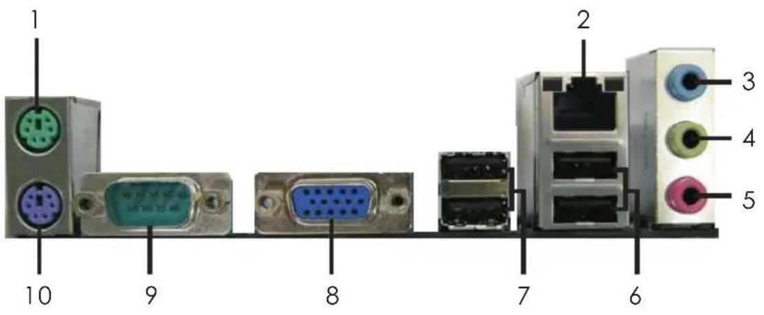
1 PS/2 Mouse Port (Green)
6 USB 2.0 Ports (USB01)
* 2 LAN RJ-45 Port 7 USB 2.0 Ports (USB23)
3 Line In (Light Blue) 8 D-Sub Port
** 4 Front Speaker (Lime)
9 COM Port
5 Microphone (Pink)
10 PS/2 Keyboard Port (Purple)
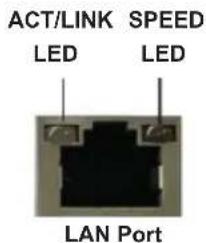
* There are two LED next to the LAN port. Please refer to the table below for the LAN port LED indications.
LAN Port LED Indications
| Activity/Link LED | SPEED LED | ||
| Status | Description | Status | Description |
| Off | No Link | Off | 10Mbps connection |
| Blinking | Data Activity | Orange | 100Mbps connection |
| On | Link Green | 1Gbps connection | |
** To enable Multi-Streaming function, you need to connect a front panel audio cable to the front panel audio header. Please refer to below steps for the software setting of Multi-Streaming. For Windows® XP:
After restarting your computer, you will find "Mixer" tool on your system. Please select "MixerToolBox", click "Enable playback multi-streaming", and click "ok". Choose "2CH" or

"4CH" and then you are allowed to select "Realtek HDA Primary output" to use Rear Speaker and Front Speaker, or select "Realtek HDA Audio 2nd output" to use front panel audio. Then reboot your system.
For Windows ^® 8 / 7 / Vista ^TM :
After restarting your computer, please double-click "Realtek HD Audio Manager" on the system tray. Set "Speaker Configuration" to "Quadraphonic" or "Stereo". Click "Device advanced settings", choose "Make front and rear output devices playbacks two different audio streams simultaneously", and click "ok". Then reboot your system.
2. Installation
This is a Micro ATX form factor motherboard. Before you install the motherboard, study the configuration of your chassis to ensure that the motherboard fits into it.
Pre-installation Precautions
Take note of the following precautions before you install motherboard components or change any motherboard settings.

Before you install or remove any component, ensure that the power is switched off or the power cord is detached from the power supply. Failure to do so may cause severe damage to the motherboard, peripherals, and/or components.
- Unplug the power cord from the wall socket before touching any component.
- To avoid damaging the motherboard components due to static electricity, NEVER place your motherboard directly on the carpet or the like. Also remember to use a grounded wrist strap or touch a safety grounded object before you handle components.
- Hold components by the edges and do not touch the ICs.
- Whenever you uninstall any component, place it on a grounded anti-static pad or in the bag that comes with the component.
- When placing screws into the screw holes to secure the motherboard to the chassis, please do not over-tighten the screws! Doing so may damage the motherboard.
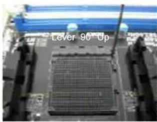
2.1 CPU Installation
Step 1. Unlock the socket by lifting the lever up to a 90° angle.
Step 2. Position the CPU directly above the socket such that the CPU corner with the golden triangle matches the socket corner with a small triangle.
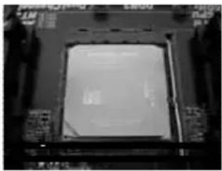
Step 3. Carefully insert the CPU into the socket until it fits in place.

The CPU fits only in one correct orientation. DO NOT force the CPU into the socket to avoid bending of the pins.
Step 4. When the CPU is in place, press it firmly on the socket while you push down the socket lever to secure the CPU. The lever clicks on the side tab to indicate that it is locked.
natural_image
Close-up of a microchip with grid pattern and blue screen (no readable text or symbols)STEP 1:
Lift Up The Socket Lever
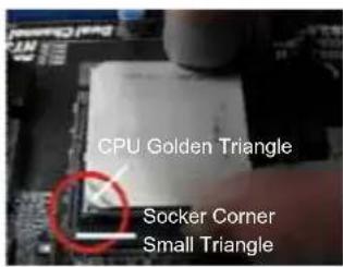
STEP 2 / STEP 3:
Match The CPU Golden Triangle
To The Socket Corner Small
Triangle
natural_image
Close-up of a computer processor's front panel showing the chip and surrounding circuitry (no visible text or symbols)STEP 4:
Push Down And Lock
The Socket Lever
2.2 Installation of CPU Fan and Heatsink
After you install the CPU into this motherboard, it is necessary to install a larger heatsink and cooling fan to dissipate heat. You also need to spray thermal grease between the CPU and the heatsink to improve heat dissipation. Make sure that the CPU and the heatsink are securely fastened and in good contact with each other. Then connect the CPU fan to the CPU FAN connector (CPU_FAN1, see Page 12, No. 4). For proper installation, please kindly refer to the instruction manuals of the CPU fan and the heatsink.
2.3 Installation of Memory Modules (DIMM)
This motherboard provides two 240-pin DDR2 (Double Data Rate 2) DIMM slots and two 240-pin DDR3 (Double Data Rate 3) DIMM slots, and supports Dual Channel Memory Technology. For dual channel configuration, you always need to install identical (the same brand, speed, size and chip-type) DDR2/DDR3 DIMM pair in the slots of the same color. In other words, you have to install identical DDR2 DIMM pair in Dual Channel (DDRII_1 and DDRII_2; Yellow slots; see p.12 No.2), or identical DDR3 DIMM pair in Dual Channel (DDR3_A1 and DDR3_B1; Blue slots; see p.12 No.3), so that Dual Channel Memory Technology can be activated. You may refer to the Dual Channel Memory Configuration Table below.
Dual Channel DDR2 Memory Configurations
(DS: Double Side, SS: Single Side)
| DDRII_1(Yellow Slot) | DDRII_2(Yellow Slot) | |
| 2 memory modules | SS | SS |
| 2 memory modules | DS | DS |
Dual Channel DDR3 Memory Configurations
(DS: Double Side, SS: Single Side)
| DDR3_A1(Black Slot) | DDR3_B1(Black Slot) | |
| 2 memory modules | SS | SS |
| 2 memory modules | DS | DS |

- If you want to install two memory modules, for optimal compatibility and reliability, it is recommended to install them in the slots of the same color. In other words, install them in the set of black slots (DDR3_A1 and DDR3_B1), or in the set of yellow slots (DDRII_1 and DDRII_2).
- If only one memory module is installed in the DIMM slot on this motherboard, it is unable to activate the Dual Channel Memory Technology.
- It is not allowed to install a DDR3 memory module into DDR2 slot or install a DDR2 memory module into DDR3 slot; otherwise, this motherboard and DIMM may be damaged.
- DDR2 and DDR3 memory modules cannot be installed on this motherboard at the same time.
- DDR3 memory module is only supported by installing AM3/AM3+CPU. DDR2 memory module is only supported by installing AM2/AM2+/AM3 CPU.
Installing a DIMM

Please make sure to disconnect power supply before adding or removing DIMMs or the system components.
Step 1. Unlock a DIMM slot by pressing the retaining clips outward.
Step 2. Align a DIMM on the slot such that the notch on the DIMM matches the break on the slot.
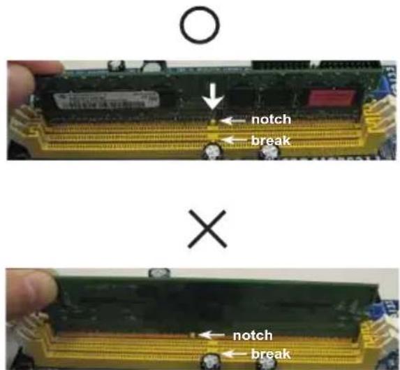

The DIMM only fits in one correct orientation. It will cause permanent damage to the motherboard and the DIMM if you force the DIMM into the slot at incorrect orientation.
Step 3. Firmly insert the DIMM into the slot until the retaining clips at both ends fully snap back in place and the DIMM is properly seated.
2.4 Expansion Slots (PCI and PCI Express Slots)
There are 2 PCI slots and 2 PCI Express slots on this motherboard.
PCI Slots: PCI slots are used to install expansion cards that have the 32-bit PCI interface.
PCIE Slots:
PCIE1 (PCIE x1 slot) is used for PCI Express x1 lane width graphics cards.
PCIE2 (PCIE x16 slot) is used for PCI Express x16 lane width graphics cards.
Installing an expansion card
Step 1. Before installing the expansion card, please make sure that the power supply is switched off or the power cord is unplugged. Please read the documentation of the expansion card and make necessary hardware settings for the card before you start the installation.
Step 2. Remove the system unit cover (if your motherboard is already installed in a chassis).
Step 3. Remove the bracket facing the slot that you intend to use. Keep the screws for later use.
Step 4. Align the card connector with the slot and press firmly until the card is completely seated on the slot.
Step 5. Fasten the card to the chassis with screws.
Step 6. Replace the system cover.
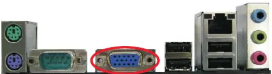
2.5 Multi Monitor Feature
This motherboard supports multi monitor feature. With the internal VGA output support and the external add-on PCI Express VGA card, you can easily enjoy the benefits of multi monitor feature.
Please refer to the following steps to set up a surround display environment:
- Install the PCI Express VGA cards on PCIE2 slot. Please refer to page 18 for proper expansion card installation procedures for details.
- Connect D-Sub monitor cable to VGA port on the I/O panel. And connect other monitor cables to the corresponding connectors of the add-on PCI Express VGA cards on PCIE2 slot.
natural_image
Exterior view of computer hardware components including VGA, CPU socket, and ports (no text or symbols visible)VGA port
-
Boot your system. Press
or to enter BIOS setup. Enter "Share Memory" option to adjust the memory capability to [32MB], [64MB], [128MB] [256MB] or [512MB] to enable the function of VGA. Please make sure that the value you select is less than the total capability of the system memory. If you do not adjust the BIOS setup, the default value of "Share Memory", [Auto], will disable VGA function when the add-on VGA card is inserted to this motherboard. -
Install the onboard VGA driver and the add-on PCI Express VGA card driver to your system. If you have installed the drivers already, there is no need to install them again.
-
Set up a multi-monitor display.
For Windows ^® XP / XP 64-bit OS:
Right click the desktop, choose "Properties", and select the "Settings" tab so that you can adjust the parameters of the multi-monitor according to the steps below.
A. Click the "Identify" button to display a large number on each monitor.
B. Right-click the display icon in the Display Properties dialog that you wish to be your primary monitor, and then select "Primary". When you use multiple monitors with your card, one monitor will always be
Primary, and all additional monitors will be designated as Secondary.
C. Select the display icon identified by the number 2.
D. Click "Extend my Windows desktop onto this monitor".
E. Right-click the display icon and select "Attached", if necessary.
F. Set the "Screen Resolution" and "Color Quality" as appropriate for the second monitor. Click "Apply" or "OK" to apply these new values.
G. Repeat steps C through E for the display icon identified by the number one, two and three.
For Windows ^® 8 / 8 64-bit / 7 / 7 64-bit / Vista ^TM / Vista ^TM 64-bit OS:
Right click the desktop, choose "Personalize", and select the "Display Settings" tab so that you can adjust the parameters of the multi-monitor according to the steps below.
A. Click the number "2" icon.
B. Click the items "This is my main monitor" and "Extend the desktop onto this monitor".
C. Click "OK" to save your change.
D. Repeat steps A through C for the display icon identified by the number three.
- Use multi monitor feature. Click and drag the display icons to positions representing the physical setup of your monitors that you would like to use. The placement of display icons determines how you move items from one monitor to another.
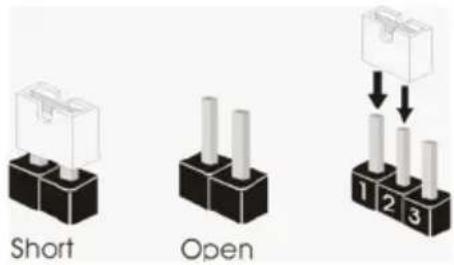
2.6 Jumpers Setup
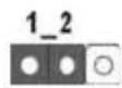
The illustration shows how jumpers are setup. When the jumper cap is placed on pins, the jumper is "Short". If no jumper cap is placed on pins, the jumper is "Open". The illustration shows a 3-pin jumper whose pin1 and pin2 are "Short" when jumper cap is placed on these 2 pins.
Jumper Setting Description
Clear CMOS Jumper
(CLRCMOS1)
(see p.12, No. 7)

Clear CMOSDefault
Note: CLRCMOS1 allows you to clear the data in CMOS. To clear and reset the system parameters to default setup, please turn off the computer and unplug the power cord from the power supply. After waiting for 15 seconds, use a jumper cap to short pin2 and pin3 on CLRCMOS1 for 5 seconds. However, please do not clear the CMOS right after you update the BIOS. If you need to clear the CMOS when you just finish updating the BIOS, you must boot up the system first, and then shut it down before you do the clear-CMOS action. Please be noted that the password, date, time, user default profile, 1394 GUID and MAC address will be cleared only if the CMOS battery is removed.

If you clear the CMOS, the case open may be detected. Please adjust the BIOS option "Clear Status" to clear the record of previous chassis intrusion status.
2.7 Onboard Headers and Connectors

Onboard headers and connectors are NOT jumpers. Do NOT place jumper caps over these headers and connectors. Placing jumper caps over the headers and connectors will cause permanent damage of the motherboard!
Floppy Connector
(33-pin FLOPPY1)
(see p.12 No. 20)
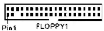

Note: Make sure the red-striped side of the cable is plugged into Pin1 side of the connector.
Primary IDE connector
(39-pin IDE1, see p.12 No. 6)
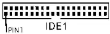
connect the blue end to the motherboard
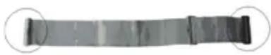
connect the black end to the IDE devices
80-conductor ATA 66/100/133 cable
Note: Please refer to the instruction of your IDE device vendor for the details.
Serial ATA2 Connectors These six Serial ATA2 (SATA2)
(SATAII_1 (PORT 0): connectors support SATA data
see p.12, No. 14) cables for internal storage
(SATAII_2 (PORT 1): devices. The current SATA2
see p.12, No. 15) interface allows up to 3.0 Gb/s
(SATAII_3 (PORT 2): data transfer rate.
see p.12, No. 12)
(SATAII_4 (PORT 3):
see p.12, No. 11)
(SATAII_5 (PORT 4):
see p.12, No. 10)
(SATAII_6 (PORT 5):
see p.12, No. 9)

SATAII_2 (PORT 1)

SATAII_1 (PORT 0)

SATAII_4 (PORT 3)

SATAII_3 (PORT 2)

SATAII_6 (PORT 5)

SATAII_5 (PORT 4)
Serial ATA (SATA) Either end of the SATA data
Data Cable cable can be connected to the
(Optional) SATA2 hard disk or the SATA2
connector on this motherboard.
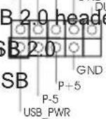
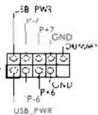
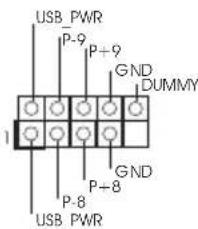
USB 2.0 Headers Besides four default USB 2.0
(9-pin USB4_5) ports on the I/O panel, there
(see p.12 No. 18) are three USB 2.0 headers on
this motherboard. Each USB
header can support two USB
2.0 ports.
(9-pin USB6_7)
(see p.12 No. 17)
(9-pin USB8_9)
(see p.12 No. 16)
Front Panel Audio Header This is an interface for the front
(9-pin HD_AUDIO1) panel audio cable that allows
(see p.12 No. 25) convenient connection and
control of audio devices.
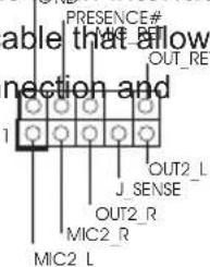

-
High Definition Audio supports Jack Sensing, but the panel wire on the chassis must support HDA to function correctly. Please follow the instruction in our manual and chassis manual to install your system.
-
If you use AC'97 audio panel, please install it to the front panel audio header as below:
A. Connect Mic_IN (MIC) to MIC2_L.
B. Connect Audio_R (RIN) to OUT2_R and Audio_L (LIN) to OUT2_L.
C. Connect Ground (GND) to Ground (GND).
D. MIC_RET and OUT_RET are for HD audio panel only. You don't need to connect them for AC'97 audio panel.
E. To activate the front mic.
For Windows ^® XP / XP 64-bit OS:
Select "Mixer". Select "Recorder". Then click "FrontMic".
For Windows ^ 8 / 8 64-bit / 7 / 7 64-bit / Vista ^TM / Vista ^TM 64-bit OS: Go to the "FrontMic" Tab in the Realtek Control panel. Adjust "Recording Volume".
SPDIF Out Connector Please connect the (2-pin SPDIF_OUT1) SPDIF_OUT connector of a (see p.12 No. 24) HDMI VGA card to this header with a cable.
System Panel Header This header accommodates (9-pin PANEL1) several system front panel (see p.12 No. 19) functions.
Connect the power switch, reset switch and system status indicator on the chassis to this header according to the pin assignments below. Note the positive and negative pins before connecting the cables.
PWRBTN (Power Switch):
Connect to the power switch on the chassis front panel. You may configure the way to turn off your system using the power switch.
RESET (Reset Switch):
Connect to the reset switch on the chassis front panel. Press the reset switch to restart the computer if the computer freezes and fails to perform a normal restart.
PLED (System Power LED):
Connect to the power status indicator on the chassis front panel. The LED is on when the system is operating. The LED keeps blinking when the sys-tem is in S1 sleep state. The LED is off when the system is in S3/S4 sleep state or powered off (S5).
HDLED (Hard Drive Activity LED):
Connect to the hard drive activity LED on the chassis front panel. The LED is on when the hard drive is reading or writing data.
The front panel design may differ by chassis. A front panel module mainly consists of power switch, reset switch, power LED, hard drive activity LED, speaker and etc. When connecting your chassis front panel module to this header, make sure the wire assignments and the pin assign-ments are matched correctly.
Chassis Speaker Header Please connect the chassis (4-pin SPEAKER 1) speaker to this header (see p.12, No. 13)
Infrared Module Header This header supports an (5-pin IR1) optional wireless transmitting (see p.12, No. 21) and receiving infrared module.
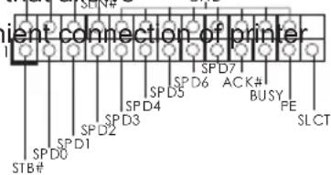
Print Port Header This is an interface for print (25-pin LPT1) port cable that allows (see p.12 No. 23) convenient connection of printer devices.
Chassis Intrusion Header This motherboard supports (2-pin CI1) CASE OPEN detection feature CND (see p.12 No. 22) that detects if the chassis cover has been removed. This feature requires a chassis with chassis intrusion detection design.
Internal Audio Connectors
(4-pin CD1)
(CD1: see p.12 No. 26)
a CD-ROM, DVD-ROM, TV
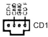
This connector allows you to receive stereo audio input from sound sources such as
tuner card, or MPEG card.
Chassis and Power Fan Connectors
(3-pin CHA_FAN1)
(see p.12 No. 8)
ground pin.
(3-pin PWR_FAN1)
(see p.12 No. 27)
to the fan connector and match the black wire to the
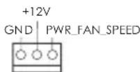
Please connect the fan cable
CPU Fan Connector Please connect the CPU fan
(4-pin CPU_FAN1) cable to the connector and
(see p.12 No. 4) match the black wife to the
ground pin.
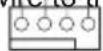
1 2 3 4

Though this motherboard provides 4-Pin CPU fan (Quiet Fan) support, the 3-Pin
CPU fan still can work successfully even without the fan speed control function.
If you plan to connect the 3-Pin CPU fan to the CPU fan connector on this
motherboard, please connect it to Pin 1-3.
Pin 1-3 Connected

3-Pin Fan Installation
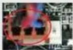
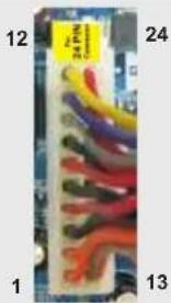
ATX Power Connector Please connect an ATX power
(24-pin ATXPWR1) supply to this connector.
(see p.12 No. 5)
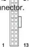

Though this motherboard provides 24-pin ATX power connector, it can still work if you adopt a traditional 20-pin ATX power supply.
To use the 20-pin ATX power supply, please plug your power supply along with Pin 1 and Pin 13.
20-Pin ATX Power Supply Installation
ATX 12V Power Connector Please connect an ATX 12V
(4-pin ATX12V1) power supply to this connector.
(see p.12 No. 1)
2.8 Serial ATA2 (SATA2) Hard Disks Installation
This motherboard adopts AMD SB710 chipset that supports Serial ATA2 (SATA2) hard disks and RAID (RAID 0, RAID 1, RAID 10 and JBOD) functions. You may install SATA2 hard disks on this motherboard for internal storage devices. This section will guide you to install the SATA2 hard disks.
STEP 1: Install the SATA2 hard disks into the drive bays of your chassis.
STEP 2: Connect the SATA power cable to the SATA2 hard disk.
STEP 3: Connect one end of the SATA data cable to the motherboard's SATA2 connector.
STEP 4: Connect the other end of the SATA data cable to the SATA2 hard disk.
2.9 Hot Plug and Hot Swap Functions for Serial ATA2 (SATA2) HDDs
This motherboard supports Hot Plug and Hot Swap functions for SATA2 in RAID / AHCI mode. AMD SB710 chipset provides hardware support for Advanced Host controller Interface (AHCI), a new programming interface for SATA host controllers developed thru a joint industry effort.

NOTE
What is Hot Plug Function?
If the SATA2 HDDs are NOT set for RAID configuration, it is called "Hot Plug" for the action to insert and remove the SATA2 HDDs while the system is still power-on and in working condition. However, please note that it cannot perform Hot Plug if the OS has been installed into the SATA2 HDD.
What is Hot Swap Function?
If SATA2 HDDs are built as RAID 1 then it is called "Hot Swap" for the action to insert and remove the SATA2 HDDs while the system is still power-on and in working condition.
2.10 Driver Installation Guide
To install the drivers to your system, please insert the support CD to your optical drive first. Then, the drivers compatible to your system can be auto-detected and listed on the support CD driver page. Please follow the order from up to bottom side to install those required drivers. Therefore, the drivers you install can work properly.
2.11 Installing Windows ^® 8 / 8 64-bit / 7 / 7 64-bit / Vista ^™ / Vista ^™ 64-bit / XP / XP 64-bit With RAID Functions
If you want to install Windows ^® 8 / 8 64-bit / 7 / 7 64-bit / Vista ^TM / Vista ^TM 64-bit / XP / XP 64-bit on a RAID disk composed of 2 or more SATA / SATA2 HDDs with RAID functions, please follow below procedures according to the OS you install.
2.11.1 Installing Windows ^® XP / XP 64-bit With RAID Functions
If you want to install Windows XP / XP 64-bit on a RAID disk composed of 2 or more SATA / SATA2 HDDs with RAID functions, please follow below steps.
STEP 1: Set up BIOS.
A. Enter BIOS SETUP UTILITY → Advanced screen Storage Configuration.
B. Set the "SATA Operation Mode" option to [RAID].
STEP 2: Make a SATA / SATA2 Driver Diskette.
A. Insert the Support CD into your optical drive to boot your system.
B. During POST at the beginning of system boot-up, press
C. When you see the message on the screen, "Generate Serial ATA driver diskette [YN]?", press
D. Then you will see these messages,
Please insert a diskette into the floppy drive.
WARNING! Formatting the floppy diskette will
lose ALL data in it!
Start to format and copy files [YN]?
Please insert a floppy diskette into the floppy drive, and press any key.
E. The system will start to format the floppy diskette and copy SATA / SATA2 drivers into the floppy diskette.
STEP 3: Use "RAID Installation Guide" to set RAID configuration.
Before you start to configure RAID function, you need to check the RAID installation guide in the Support CD for proper configuration. Please refer to the BIOS RAID installation guide part of the document in the following path in the Support CD:
.. \ RAID Installation Guide
STEP 4: Install Windows ^® XP / XP 64-bit OS on your system.
After step 1, 2, 3, you can start to install Windows XP / XP 64-bit OS on your system. At the beginning of Windows ^® setup, press F6 to install a third-party RAID driver. When prompted, insert the SSATA / SATA2 driver diskette containing the AMD RAID driver. After reading the floppy disk, the driver will be presented. Select the driver to install according to the OS you install.
2.11.2 Installing Windows ^® 8 / 8 64-bit / 7 / 7 64-bit / Vista ^™ / Vista ^™ 64-bit With RAID Functions
If you want to install Windows ^® 8 / 8 64-bit / 7 / 7 64-bit / Vista ^TM / Vista ^TM 64-bit on a RAID disk composed of 2 or more SATA / SATA2 HDDs with RAID functions, please follow below steps.
STEP 1: Set up BIOS.
A. Enter BIOS SETUP UTILITY → Advanced screen Storage Configuration. B. Set the "SATA Operation Mode" option to [RAID].
STEP 2: Use "RAID Installation Guide" to set RAID configuration.
Before you start to configure RAID function, you need to check the RAID installation guide in the Support CD for proper configuration. Please refer to the BIOS RAID installation guide part of the document in the following path in the Support CD:
.. \ RAID Installation Guide
STEP 3: Install Windows ^® 8 / 8 64-bit / 7 / 7 64-bit / Vista ^TM / Vista ^TM 64-bit OS on your system.
2.12 Installing Windows ^® 8 / 8 64-bit / 7 / 7 64-bit / Vista ^TM / Vista ^TM 64-bit / XP / XP 64-bit Without RAID Functions
If you want to install Windows ^® 8 / 8 64-bit / 7 / 7 64-bit / Vista ^TM / Vista ^TM 64-bit / XP / XP 64-bit OS on your SATA / SATA2 HDDs without RAID functions, please follow below procedures according to the OS you install.
2.12.1 Installing Windows ^® XP / XP 64-bit Without RAID Functions
If you want to install Windows ^® XP / XP 64-bit on your SATA / SATA2 HDDs without RAID functions, please follow below steps.
Using SATA / SATA2 HDDs with NCQ and Hot Plug functions (AHCI mode)
STEP 1: Set up BIOS.
A. Enter BIOS SETUP UTILITY → Advanced screen Storage Configuration. B. Set the "SATA Operation Mode" option to [AHCI].
STEP 2: Install Windows ^® XP / XP 64-bit OS on your system.
You can start to install Windows® XP / XP 64-bit OS on your system. At the beginning of Windows® setup, press F6 to install a third-party AHCI driver. When prompted, insert the SATA / SATA2 driver diskette containing the AMD AHCI driver. After reading the floppy disk, the driver will be presented. Select the driver to install according to the OS you install.
Using SATA / SATA2 HDDs without NCQ and Hot Plug functions (IDE mode)
STEP 1: Set up BIOS.
A. Enter BIOS SETUP UTILITY → Advanced screen Storage Configuration. B. Set the "SATA Operation Mode" option to [IDE].
STEP 2: Install Windows ^® XP / XP 64-bit OS on your system.
2.12.2 Installing Windows ^® 8 / 8 64-bit / 7 / 7 64-bit / Vista ^TM / Vista ^TM 64-bit Without RAID Functions
If you want to install Windows ^® 8 / 8 64-bit / 7 / 7 64-bit / Vista ^TM / Vista ^TM 64-bit on your SATA / SATA2 HDDs without RAID functions, please follow below steps.
Using SATA / SATA2 HDDs with NCQ and Hot Plug functions (AHCI mode)
STEP 1: Set up BIOS.
A. Enter BIOS SETUP UTILITY → Advanced screen Storage Configuration.
B. Set the "SATA Operation Mode" option to [AHCI].
STEP 2: Install Windows ^® 8 / 8 64-bit / 7 / 7 64-bit / Vista ^TM / Vista ^TM 64-bit OS on your system.
Using SATA / SATA2 HDDs without NCQ and Hot Plug functions (IDE mode)
STEP 1: Set up BIOS.
A. Enter BIOS SETUP UTILITY → Advanced screen Storage Configuration.
B. Set the "SATA Operation Mode" option to [IDE].
STEP 2: Install Windows ^® 8 / 8 64-bit / 7 / 7 64-bit / Vista ^TM / Vista ^TM 64-bit OS on your system.
2.13 Untied Overclocking Technology
This motherboard supports Untied Overclocking Technology, which means during overclocking, FSB enjoys better margin due to fixed PCI / PCIE buses. Before you enable Untied Overclocking function, please enter "Overclock Mode" option of BIOS setup to set the selection from [Auto] to [Manual]. Therefore, CPU FSB is untied during overclocking, but PCI / PCIE buses are in the fixed mode so that FSB can operate under a more stable overclocking environment.
Please refer to the warning on page 8 for the possible overclocking risk before you apply Untied Overclocking Technology.
3. BIOS SETUP UTILITY
3.1 Introduction
This section explains how to use the BIOS SETUP UTILITY to configure your system. The SPI Memory on the motherboard stores the BIOS SETUP UTILITY. You may run the BIOS SETUP UTILITY when you start up the computer. Please press during the Power-On-Self-Test (POST) to enter the BIOS SETUP UTILITY, otherwise, POST will continue with its test routines.
If you wish to enter the BIOS SETUP UTILITY after POST, restart the system by pressing

Because the BIOS software is constantly being updated, the following BIOS setup screens and descriptions are for reference purpose only, and they may not exactly match what you see on your screen.
3.1.1 BIOS Menu Bar
The top of the screen has a menu bar with the following selections:
Main To set up the system time/date information
OC Tweaker To set up overclocking features
Advanced To set up the advanced BIOS features
H/W Monitor To display current hardware status
Boot To set up the default system device to locate and load the Operating System
Security To set up the security features
Exit To exit the current screen or the BIOS SETUP UTILITY
Use <←> key or <→ key to choose among the selections on the menu bar, and then press
3.1.2 Navigation Keys
Please check the following table for the function description of each navigation key.
Navigation Key(s) Function Description
← / -Moves cursor left or right to select Screens
↑ / ↓ Moves cursor up or down to select items
+ / - To change option for the selected items
3.2 Main Screen
When you enter the BIOS SETUP UTILITY, the Main screen will appear and display the system overview.
![BIOSSETUPUTILITY Main OC Tweaker Advanced H/W Monitor Boot Security Exit SystemOverview SystemTime [17:00:09] SystemDate [Tue 06/11/2013] BIOSVersion :960GC-GSFXP1.00 ProcessorType :AMDPhenom(tm)9550Quad-Core Processor(64bit) ProcessorSpeed :2200MHz MicrocodeUpdate :100F23/0 L1CacheSize :512KB L2CacheSize :2048KB L3CacheSize :2048KB TotalMemory : 1024MBwith128MBsharedmemory Single-ChannelMemoryMode DDRII_A1 : 1024MB/266MIIzDDR2_533 DDRII_A2 : None Use[Enter],[TAB] or[SHIFT-TAB]to selectafield. Use[+|or|-]to configuresystemTime. -- SelectScreen ↑ SelectItem +- ChangeField Tab SelectField F1 GeneralHelp F9 LoadDefaults F10 SaveandExit ESC Exit v02.54 (C) Copyright1985-2005,AmericanMegatrends,Inc.](/content/2026/06/1278175/images/55b29a0601d4cc16f819306c981a600e11e31488622825bc917c5a557dccee00.jpg)
System Time [Hour:Minute:Second]
Use this item to specify the system time.
System Date [Day Month/Date/Year]
Use this item to specify the system date.
3.3 OC Tweaker Screen
In the OC Tweaker screen, you can set up overclocking features.
![BIOSSETUPUTILITY Main OCTweaker AdvancedII/WMonitorBootSecurityExit CPUConfiguration OverclockMode [Auto] CPUFrequency(MHz) [400] PCIEFrequency(MHz) [100] SpreadSpectrum [Auto] BootFailureGuard [Enabled] BootFailureGuardCount [3] AdvancedClockCalibration [Disabled] ProcessorMaximumFrequency x31.56300MIIZ NorthBridge MaximumFrequency x31.062 00MHz ProcessorMaximumVoltage 1,5500V Multiplier/VoltageChange [Auto] HTBusSpeed [Auto] HTBusWidth [Auto] MemoryConfiguration MemoryClock [Auto] Overclockingmaycause damageltoyourCPUand motherboard. Itshouldbedoneat yourownriskand expense. -- SelectScreen 11 SelectItem EnterGotoSubScreen F1GeneralHelp F9LoadDefaults F10SaveandExit ESCExit v02.54 (C) Copyright1985-2005,AmericanMegatrends,Inc.](/content/2026/06/1278175/images/169af9d686a3e367170c88395c5b5763d28bc8c374a39c42ccc2df6aac0f72a6.jpg)
CPU Configuration
Overclock Mode
Use this to select Overclock Mode. The default value is [Auto]. Configuration options: [Auto], [CPU, PCIE, Sync.], [CPU, PCIE, Async.] and [Optimized].
CPU Frequency (MHz)
Use this option to adjust CPU frequency.
PCIE Frequency (MHz)
Use this option to adjust PCIE frequency.
Spread Spectrum
This feature will be set to [Enabled] as default. Configuration options: [Disabled] and [Enabled].
Boot Failure Guard
Enable or disable the feature of Boot Failure Guard.
Boot Failure Guard Count
Enable or disable the feature of Boot Failure Guard Count.
Advanced Clock Calibration
This allows you to adjust Advanced Clock Calibration feature. The default value is [Disabled]. Configuration options: [Disabled], [Auto], [All Cores] and [PerCore]. If you select [All Cores], you will see the option "Value (All Cores)". Configuration options: [+12%] to [-12%]. If you select [Per Core], you will see the options "Value (Core 0)", "Value (Core 1)", "Value (Core 2)" and "Value (Core 3)". Configuration options: [+12%] to [-12%].
Processor Maximum Frequency
It will display Processor Maximum Frequency for reference.
North Bridge Maximum Frequency
It will display North Bridge Maximum Frequency for reference.
Processor Maximum Voltage
It will display Processor Maximum Voltage for reference.
Multiplier/Voltage Change
This item is set to [Auto] by default. If it is set to [Manual], you may adjust the value of Processor Frequency and Processor Voltage. However, it is recommended to keep the default value for system stability.
![BIOSETUPUTILITY Main OCTweaker AdvancedH/WMonitorBootSecurityExit CPUConfiguration OverclockMode [Auto] CPUFrequency(MHz) [400] PCIEFrequency(MHz) [100] SpreadSpectrum [Auto] BootFailureGuard [Enabled] BootFailureGuardCount [3] AdvancedClockCalibration [Disabled] ProcessorMaximumFrequency x31.56300MHZ NorthBridge MaximumFrequency x31.062 00MHz ProcessorMaximumVoltage 1.5500V Multiplier/VoltageChange [Manual] ITBusSpeed [Auto] ITBusWidth [Auto] MemoryConfiguration MemoryClock [Auto] Overclockingmaycause damagetoyourCPUand motherboard. Itshouldbcdoncat yourownriskand expense. -- SelectScreen 11 SelectItem EnterGotoSubScreen F1GeneralHelp F9LoadDefaults F10SaveandExit ESCExit v02.54(C)Copyright1985-2005,AmericanMegatrends,Inc.](/content/2026/06/1278175/images/1a2689c2482de9f4403d0389508e89c44982b8fde7d7392da9c315b72e0e88af.jpg)
CPU Frequency Multiplier
For safety and system stability, it is not recommended to adjust the value of this item.
Processor Voltage
It allows you to adjust the value of processor voltage. However, for safety and system stability, it is not recommended to adjust the value of this item.
NB Frequency Multiplier
For safety and system stability, it is not recommended to adjust the value of this item.
HT Bus Speed
This feature allows you selecting Hyper-Transport bus speed.
HT Bus Width
This feature allows you selecting Hyper-Transport bus width.
Memory Configuration
Memory Clock
This item can be set by the code using [Auto]. You can set one of the standard values as listed for DDR2 memory modules: [200MHz DDR2_400], [266MHz DDR2_533], [333MHz DDR2_667] and [400MHz DDR2_800]. If you adopt Phenom CPU, there is one more option: [533MHz DDR2_1066].
You can set one of the standard values as listed for DDR3 memory modules: [400MHz DDR3_800], [533MHz DDR3_1066], [667MHz DDR3_1333] and [800MHz DDR3_1600].
DRAM Voltage
Use this to select DRAM voltage. The default value is [Auto].
Memory Timing
![BIOSETUPUTILITY OCTweaker MemoryTiming PowerDownEnable [Enabled] BankInterleaving [Auto] ChannelInterleaving [Auto] CASLatency(CL) [Auto] TRCD [Auto] TRP [Auto] TRAS [Auto] CommandRate [Auto] TRC [Auto] TWR [Auto] TRFC [Auto] TRRD [Auto] TWTR [Auto] TRTP [Auto] -- SelectScreen 1↓ SelectItem +-ChangeOption F1GeneralHelp F9LoadDconfaults F10SaveandExit ESCExit v02.54(C)Copyright1985-2003,AmericanMegatrends,Inc.](/content/2026/06/1278175/images/5296e4ac2ab3c8a4519d9166f9750ddd66a82b44b3723bde4f150af24f9ca884.jpg)
Power Down Enable
Use this item to enable or disable DDR power down mode.
Bank Interleaving
Interleaving allows memory accesses to be spread out over banks on the same node, or across nodes, decreasing access contention.
Channel Interleaving
It allows you to enable Channel Memory Interleaving. The default value for DDR2 is [Hash 1]. The default value for DDR3 is [Hash 2].
CAS Latency (CL)
Use this item to adjust the means of memory accessing. The default value is [Auto].
TRCD
Use this to adjust TRCD values. The default value is [Auto].
TRP
Use this to adjust TRP values. The default value is [Auto].
TRAS
Use this to adjust TRAS values. The default value is [Auto].
Command Rate
Use this item to change Command Rate Auto/Manual setting. Min: 1N.
Max: 2N. The default is [Auto].
TRC
Use this to adjust TRC values. The default value is [Auto].
TWR
Use this to adjust TWR values. The default value is [Auto].
TRFC
Use this to adjust TRFC values. The default value is [Auto].
TRRD
Use this to adjust TRRD values. The default value is [Auto].
TWTR
Use this to adjust TWTR values. The default value is [Auto].
TRTP
Use this to adjust TRTP values. The default value is [Auto].
Chipset Settings
NB Voltage
Use this to select NB voltage. The default value is [Auto].
SB Voltage
Use this to select SB voltage. The default value is [Auto].
+1.8V Voltage
Use this to select +1.8V voltage. The default value is [Auto].
Would you like to save current setting user defaults?
In this option, you are allowed to load and save three user defaults according to your own requirements.
3.4 Advanced Screen
In this section, you may set the configurations for the following items: CPU Configuration, Chipset Configuration, ACPI Configuration, Storage Configuration, PCIPnP Configuration, Floppy Configuration, Super IO Configuration and USB Configuration.
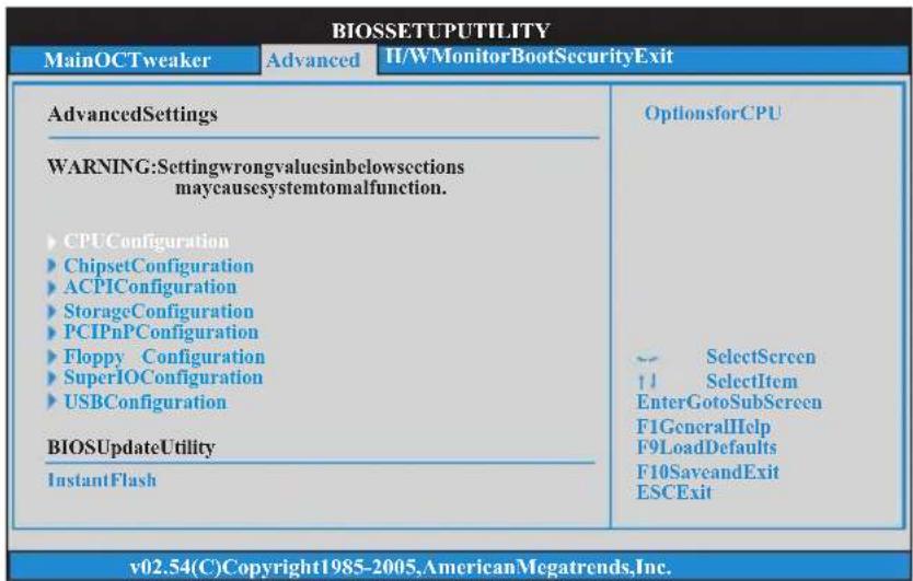

Setting wrong values in this section may cause the system to malfunction.
Instant Flash
Instant Flash is a BIOS flash utility embedded in Flash ROM. This convenient BIOS update tool allows you to update system BIOS without entering operating systems first like MS-DOS or Windows®Just launch this tool and save the new BIOS file to your USB flash drive, floppy disk or hard drive, then you can update your BIOS only in a few clicks without preparing an additional floppy diskette or other complicated flash utility. Please be noted that the USB flash drive or hard drive must use FAT32/16/12 file system. If you execute Instant Flash utility, the utility will show the BIOS files and their respective information. Select the proper BIOS file to update your BIOS, and reboot your system after BIOS update process completes.
3.4.1 CPU Configuration
![BIOSSETUPUTILITY Advanced CPUConfiguration Cool'n'Quiet [Enabled] SecureVirtualMachine [Enabled] EnhancedHaltState(C1F) [Disabled] CPUHTC [Enabled] CPUThermalThrottle [Auto] -- SelectScreen 11 SelectItem +-ChangeOption F1GeneralHelp F9LoadDefaults F10SaveandExit ESCExit v02.54(C)Copyright1985-2003,AmericanMegatrends,Inc.](/content/2026/06/1278175/images/47e9d4de3b04ae1e7ce9608a6e3bdeb757070a2f7fe8110decabaf45abbe1489.jpg)
Cool 'n' Quiet
Use this item to enable or disable AMD's Cool 'n' Quiet ^TM technology. The default value is [Enabled]. Configuration options: [Enabled] and [Disabled]. If you install Windows ^ 8 / 7 / Vista ^TM and want to enable this function, please set this item to [Enabled]. Please note that enabling this function may reduce CPU voltage and memory frequency, and lead to system stability or compatibility issue with some memory modules or power supplies. Please set this item to [Disable] if above issue occurs.
Secure Virtual Machine
When this option is set to [Enabled], a VMM (Virtual Machine Architecture) can utilize the additional hardware capabilities provided by AMD-V. The default value is [Enabled]. Configuration options: [Enabled] and [Disabled].
Enhance Halt State (C1E)
All processors support the Halt State (C1). The C1 state is supported through the native processor instructions HLT and MWAIT and requires no hardware support from the chipset. In the C1 power state, the processor maintains the context of the system caches.
CPU Thermal Throttle
Use this item to enable CPU internal thermal control mechanism to keep the CPU from overheated. The default value is [Auto].
3.4.2 Chipset Configuration
![BIOSSETUPUTILITY Advanced ChipsetSettings OnboardHDAudio [Auto] FrontPanel [Auto] OnboardLan [Enabled] PrimaryGraphicsAdapter [PCI] -- SelectScreen ↑ SelectItem +-ChangeOption F1GeneralHelp F9LoadDefaults F10SaveandExit ESCExit v02.54(C)Copyright1985-2003,AmericanMegatrends,Inc.](/content/2026/06/1278175/images/ebf4839437e4b30b64f8d2cd59d689ce7d77535c0923e706bd31bc4a5503f1e9.jpg)
Onboard HD Audio
Select [Auto], [Enabled] or [Disabled] for the onboard HD Audio feature. If you select [Auto], the onboard HD Audio will be disabled when PCI Sound Card is plugged.
Front Panel
Select [Auto] or [Disabled] for the onboard HD Audio Front Panel.
Onboard Lan
This allows you to enable or disable the onboard Lan feature.
Primary Graphics Adapter
This item will switch the PCI Bus scanning order while searching for video card. It allows you to select the type of Primary VGA in case of multiple video controllers. The default value of this feature is [PCI]. Configuration options: [Onboard], [PCI] and [PCI Express].
3.4.3 ACPI Configuration
| BIOSETUPUTILITY | ||
| Advanced | ||
| ACPISettings | Selectauto-detector disabletheSTR feature. | |
| SuspendToRAM | [Auto] | |
| CheckReadyBit | [Auto] | |
| AwayModeSupport | [Disabled] | |
| RestoreonAC/PowerLoss | [PowerOff] | |
| Ring-InPowerOn | [Disabled] | |
| PCIDevicesPowerOn | [Disabled] | |
| PS/2KeyboardPowerOn | [Disabled] | |
| RTCAIarmPowerOn | [ByOS] | |
| ACPIHPETTable | [Enabled] | |
| v02,54(C)Copyright1985-2003,AmericanMegatrends,Inc. | ||
Suspend to RAM
Use this item to select whether to auto-detect or disable the Suspend-to-RAM feature. Select [Auto] will enable this feature if the OS supports it.
Check Ready Bit
Use this item to enable or disable the feature Check Ready Bit.
Away Mode Support
Use this item to enable or disable Away Mode support under Windows ^ XP Media Center OS. The default value is [Disabled].
Restore on AC/Power Loss
This allows you to set the power state after an unexpected AC/power loss. If [Power Off] is selected, the AC/power remains off when the power recovers. If [Power On] is selected, the AC/power resumes and the system starts to boot up when the power recovers.
Ring-In Power On
Use this item to enable or disable Ring-In signals to turn on the system from the power-soft-off mode.
PCI Devices Power On
Use this item to enable or disable PCI devices to turn on the system from the power-soft-off mode.
PS/2 Keyboard Power On
Use this item to enable or disable PS/2 keyboard to turn on the system from the power-soft-off mode.
RTC Alarm Power On
Use this item to enable or disable RTC (Real Time Clock) to power on the system.
ACPI HPET table
Use this item to enable or disable ACPI HPET Table. The default value is [Enabled]. Please set this option to [Enabled] if you plan to use this motherboard to submit Windows® certification.
3.4.4 Storage Configuration
![BIOSETUPUTILITY Advanced StorageConfiguration OnboardSATAController SATAOperationMode SATAIDECombinedMode IDE1Master IDE1Slave SATAII_1 SATAII_2 SATAII_3 SATAII_4 SATAII_5 SATAII_6 [Enabled] [AHCI] [Enabled] [HardDisk] [NotDetected] [NotDetected] [NotDetected] Configureonboard serialATA controller. -- SelectScreen ↑ SelectItem +-ChangeOption F1GeneralHelp F9LoadDefaults F10SaveandExit ESCExit v02.54(C)Copyright1985-2003,AmericanMegatrends,Inc.](/content/2026/06/1278175/images/959d1dcb3377c61e8c7f37a6c633b98d3e9af7cd11df4fa50c0a1c7d8239ef39.jpg)
Onboard SATA Controller
Use this item to enable or disable the "Onboard SATA Controller" feature.
SATA Operation Mode
Use this item to adjust Onboard SATA Operation Mode. The default value of this option is [AHCI]. Configuration options: [AHCI], [IDE] and [RAID].

If you set this item to RAID mode, it is suggested to install SATA ODD driver on SATAII_5 (PORT 4) and SATAII_6 (PORT 5) ports.
SATA IDE Combined Mode
This item is for SATAII_5 (PORT 4) and SATAII_6 (PORT 5) ports. Use this item to enable or disable SATA IDE combined mode. The default value is [Enabled].

If you want to build RAID on SATAII_5 (PORT 4) and SATAII_6 (PORT 5) ports, please disable this item.
3.4.5 PCIPnP Configuration
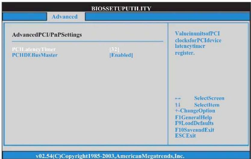

Setting wrong values in this section may cause the system to malfunction.
PCI Latency Timer
The default value is 32. It is recommended to keep the default value unless the installed PCI expansion cards?specifications require other settings.
PCI IDE BusMaster
Use this item to enable or disable the PCI IDE BusMaster feature.
3.4.6 Floppy Configuration
In this section, you may configure the type of your floppy drive.
![BIOSSETUPUTILITY Advanced FloppyConfiguration FloppyA [Disabled] Selectthetypeof floppydrive connectedtothe system. ← SelectScreen 11 SelectItem +-ChangeOption F1GeneralHelp F9LoadDefaults F10SaveandExit ESCExit v02.54(C)Copyright1985-2003,AmericanMegatrends,Inc.](/content/2026/06/1278175/images/85399aeb7d5a1922e9d42234897e171812483eabb5248bd95f248891ea93d0fc.jpg)
3.4.7 Super IO Configuration
![BIOSETUPUTILITY Advanced ConfigureSuperIOChipset OnBoardFloppyController [Disabled] SerialPortAddress [3F8/IRQ4] InfraredPortAddress [Disabled] AllowBIOStoEnable orDisableFloppy Controller. -- SelectScreen 11 SelectItem +-ChangeOption F1GeneralHelp F9LoadDefaults F10SaveandExit ESCExit v02.54(C)Copyright1985-2003.AmericanMegatrends,Inc.](/content/2026/06/1278175/images/12c950a50796b9a7e7a71aa076d9f684d30d5be766bb91bbe3fe53ebe46a35eb.jpg)
OnBoard Floppy Controller
Use this item to enable or disable floppy drive controller.
Serial Port Address
Use this item to set the address for the onboard serial port. Configuration options: [3F8 / IRQ4] and [3E8 / IRQ4].
Infrared Port
Use this item to enable or disable the onboard infrared port.
Infrared Port Address
Use this item to set the address for the onboard infrared port.Configuration options: [2F8 / IRQ3] and [2E8 / IRQ3].
3.4.8 USB Configuration
![BIOSSETUPUTILITY Advanced USBConfiguration USB2.0Controller [Enabled] USB2.0Support [Enabled] LegacyUSBSupport [Enabled] USBKeyboard/RemotePowerOn [Disabled] USBMousePowerOn [Disabled] Toenablecordisable theonboardUSB controllers. -- SelectScreen 11 SelectItem +-ChangeOption F1GeneralHelp F91LoadDefaults F10SaveandExit ESCExit v02.54(C)Copyright1985-2005,AmericanMegatrends,Inc.](/content/2026/06/1278175/images/b34108e01c626a1903bfcb7b3626dab5a07367a00e021cbf77a1b0cb89c2d720.jpg)
USB 2.0 Controller
Use this item to enable or disable the use of USB 2.0 controller.
USB 2.0 Support
Use this option to enable or disable support for USB 2.0 devices. The default value is [Enabled].
Legacy USB Support
Use this option to select legacy support for USB devices. There are four configuration options: [Enabled], [Auto], [Disabled] and [BIOS Setup Only]. The default value is [Enabled]. Please refer to below descriptions for the details of these four options:
[Enabled] - Enables support for legacy USB.
[Auto] - Enables legacy support if USB devices are connected.
[Disabled] - USB devices are not allowed to use under legacy OS and BIOS setup when [Disabled] is selected. If you have USB compatibility issue, it is recommended to select [Disabled] to enter OS.
[BIOS Setup Only] - USB devices are allowed to use only under BIOS setup and Windows / Linux OS.
USB Keyboard/Remote Power On
Use this item to enable or disable the system to wake from S5 using USB Keyboard/Remote.
USB Mouse Power On
Use this item to enable or disable the system to wake from S5 using USB Mouse.
3.5 Hardware Health Event Monitoring Screen
In this section, it allows you to monitor the status of the hardware on your system, including the parameters of the CPU temperature, motherboard temperature, CPU fan speed, chassis fan speed, and the critical voltage.
| BIOSSETUPUTILITY | ||
| MainOCTweakerAdvanced | H/WMonitor | BootSecurityExit |
| HardwareHealthEventMonitoring | Enable/Disable CPUQuietFan Function. | |
| CPUTemperature | :37C/98F * | |
| M/BTemperature | :27C/80F * | |
| CPUFanSpeed | :4722RPM | |
| ChassisFanSpeed | :N/A | |
| PowerFanSpeed | :1.216V | |
| Vcore | :3.248V | |
| +3.30V | :5.136V | |
| +5.00V | :12.091V | |
| +12.00V | ||
| CPUFanSetting | SelectScreen SelectItem F1GeneralHelp F9LoadDefaults F10SaveandExit ESCExit | |
| CaseOpenFeature|Disabled| | ||
| v02.54(C)Copyright1985-2003,AmericanMegatrends,Inc. | ||
CPU Fan Setting
This allows you to set the CPU fan speed. Configuration options: [Full On] and [Automatic Mode]. The default is value [Full On].
Case Open Feature
This allows you to enable or disable case open detection feature. The default is value [Disabled].
Clear Status
This option appears only when the case open has been detected. Use this option to keep or clear the record of previous chassis intrusion status.
3.6 Boot Screen
In this section, it will display the available devices on your system for you to configure the boot settings and the boot priority.
![BIOSETUPUTILITY MainOCTweakerAdvancedH/WMonitor Boot SecurityExit BootSettings ► BootSettingsConfiguration 1stBootDevice [1stFloppyDevice] 2ndBootDevice [HDD:PM-HDS722580VL] ► HardDiskDrives ► RemovableDrives ConfigureSettings duringSystemBoot. -- SelectScreen ↑ SelectItem EnterGotoSubScreen F1GeneralHelp F9LoadDefaults F10SaveandExit ESCExit v02.54(C)Copyright1985-2005,AmericanMegatrends,Inc.](/content/2026/06/1278175/images/4152346cf096d63cec729f1c0f16a24d2755b9ef7ecfeb99126748287a678711.jpg)
3.6.1 Boot Settings Configuration
![BIOSETUPUTILITY Boot BootSettingsConfiguration FullScreenLogo [Enabled] AddOnROMDisplay [Enabled] BootFromOnboardLAN [Disabled] BootupNum-Lock [ON] Disabled:Displays normalPOSTmessages. Enabled:DisplaysOEM LogoinsteadofPOST messages. -- SelectScreen ↑ SelectItem +-ChangeOption F1GeneralHelp F9LoadDefaults F10SaveandExit ESCExit v02.54(C)Copyright1985-2003,AmericanMegatrends,Inc.](/content/2026/06/1278175/images/655b79f33fa12ffcaf83a99f899abf90669552bc5dd8113a7cd1482030d1b88e.jpg)
Full Screen Logo
Use this item to enable or disable OEM Logo. The default value is [Enabled].
AddOn ROM Display
Use this option to adjust AddOn ROM Display. If you enable the option "Full Screen Logo" but you want to see the AddOn ROM information when the system boots, please select [Enabled]. Configuration options: [Enabled] and [Disabled]. The default value is [Enabled].
Boot From Onboard LAN
Use this item to enable or disable the Boot From Onboard LAN feature.
Bootup Num-Lock
If this item is set to [On], it will automatically activate the Numeric Lock function after boot-up.
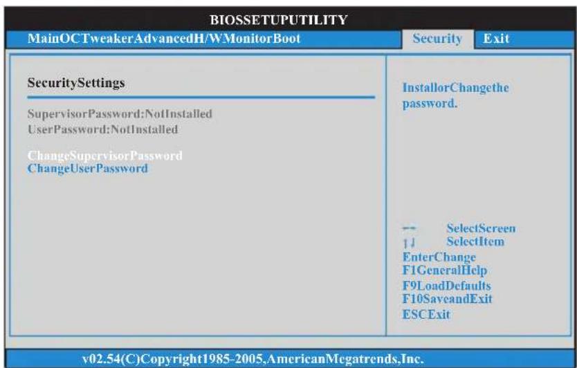
3.7 Security Screen
In this section, you may set or change the supervisor/user password for the system.
For the user password, you may also clear it.
3.8 Exit Screen
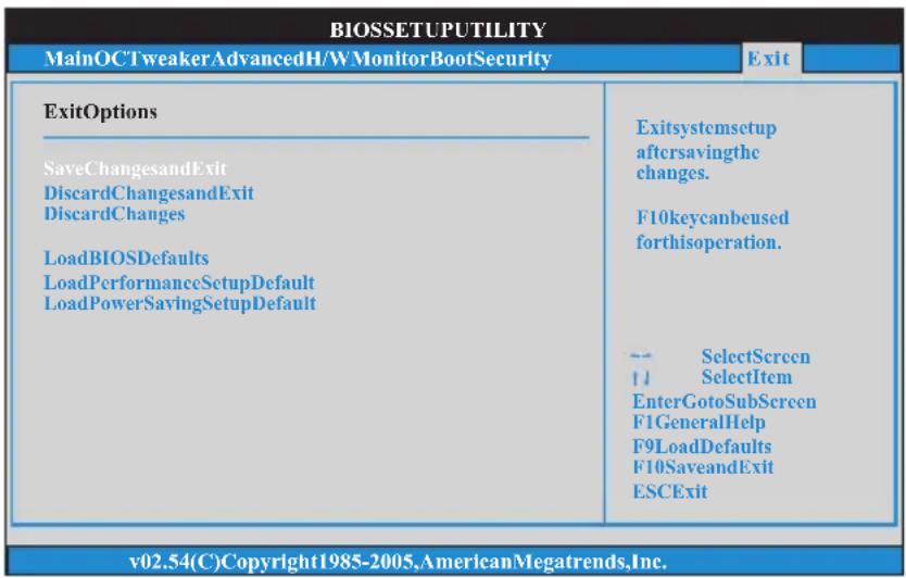
Save Changes and Exit
When you select this option, it will pop-out the following message, "Save configuration changes and exit setup?" Select [OK] to save the changes and exit the BIOS SETUP UTILITY.
Discard Changes and Exit
When you select this option, it will pop-out the following message, "Discard changes and exit setup?" Select [OK] to exit the BIOS SETUP UTILITY without saving any changes.
Discard Changes
When you select this option, it will pop-out the following message, "Discard changes?" Select [OK] to discard all changes.
Load BIOS Defaults
Load BIOS default values for all the setup questions. F9 key can be used for this operation.
Load Performance Setup Default
This performance setup default may not be compatible with all system configurations. If system boot failure occurs after loading, please resume optimal default settings. F5 key can be used for this operation.
Load Power Saving Setup Default
Load power saving setup default. F6 key can be used for this operation.
4. Software Support
4.1 Install Operating System
This motherboard supports various Microsoft® Windows® operating systems: 8 / 8 64-bit / 7 / 7 64-bit / Vista™ / Vista™ 64-bit / XP / XP Media Center / XP 64-bit. Because motherboard settings and hardware options vary, use the setup procedures in this chapter for general reference only. Refer to your OS documentation for more information.
4.2 Support CD Information
The Support CD that came with the motherboard contains necessary drivers and useful utilities that enhance the motherboard features.
4.2.1 Running The Support CD
To begin using the support CD, insert the CD into your CD-ROM drive. The CD automatically displays the Main Menu if “AUTORUN” is enabled in your computer. If the Main Menu did not appear automatically, locate and double click on the file “ASSETUP.EXE” from the BIN folder in the Support CD to display the menus.
4.2.2 Drivers Menu
The Drivers Menu shows the available devices drivers if the system detects the installed devices. Please install the necessary drivers to activate the devices.
4.2.3 Utilities Menu
The Utilities Menu shows the applications software that the motherboard supports. Click on a specific item then follow the installation wizard to install it.
4.2.4 Contact Information
If you need to contact ASRock or want to know more about ASRock, welcome to visit ASRock's website at http://www.asrock.com; or you may contact your dealer for further information.
- Copyright Notice:
- Disclaimer:
- CALIFORNIA, USA ONLY
- Contents
- Introduction ...... 5
- Installation 14
- BIOS SETUP UTILITY 32
- Software Support 52
- Introduction
- Package Contents
- ASRock Reminds You...
- Specifications
- WARNING
- CAUTION!
- Unique Features
- ASRock OC Tuner
- ASRock Intelligent Energy Saver
- ASRock Instant Boot
- ASRock Instant Flash
- ASRock OC DNA
- ASRock APP Charger
- ASRock XFast USB
- ASRock XFast LAN
- ASRock XFast RAM
- ASRock X-Boost
- I/O Panel
- Installation
- Pre-installation Precautions
- CPU Installation
- Installation of CPU Fan and Heatsink
- Installation of Memory Modules (DIMM)
- Installing a DIMM
- Expansion Slots (PCI and PCI Express Slots)
- PCIE Slots:
- Installing an expansion card
- Multi Monitor Feature
- For Windows ® XP / XP 64-bit OS:
- For Windows ® 8 / 8 64-bit / 7 / 7 64-bit / Vista TM / Vista TM 64-bit OS:
- Jumpers Setup
- Jumper Setting Description
- Onboard Headers and Connectors
- Floppy Connector
- Primary IDE connector
- Serial ATA2 Connectors These six Serial ATA2 (SATA2)
- USB 2.0 Headers Besides four default USB 2.0
- Front Panel Audio Header This is an interface for the front
- PWRBTN (Power Switch):
- RESET (Reset Switch):
- PLED (System Power LED):
- HDLED (Hard Drive Activity LED):
- Serial ATA2 (SATA2) Hard Disks Installation
- Hot Plug and Hot Swap Functions for Serial ATA2 (SATA2) HDDs
- NOTE
- What is Hot Plug Function?
- What is Hot Swap Function?
- Driver Installation Guide
- Installing Windows ® 8 / 8 64-bit / 7 / 7 64-bit / Vista ™ / Vista ™ 64-bit / XP / XP 64-bit With RAID Functions
- Installing Windows ® XP / XP 64-bit With RAID Functions
- STEP 1: Set up BIOS.
- STEP 2: Make a SATA / SATA2 Driver Diskette.
- STEP 3: Use "RAID Installation Guide" to set RAID configuration.
- .. \ RAID Installation Guide
- STEP 4: Install Windows ® XP / XP 64-bit OS on your system.
- Installing Windows ® 8 / 8 64-bit / 7 / 7 64-bit / Vista ™ / Vista ™ 64-bit With RAID Functions
- STEP 2: Use "RAID Installation Guide" to set RAID configuration.
- Installing Windows ® 8 / 8 64-bit / 7 / 7 64-bit / Vista TM / Vista TM 64-bit / XP / XP 64-bit Without RAID Functions
- Installing Windows ® XP / XP 64-bit Without RAID Functions
- STEP 2: Install Windows ® XP / XP 64-bit OS on your system.
- Installing Windows ® 8 / 8 64-bit / 7 / 7 64-bit / Vista TM / Vista TM 64-bit Without RAID Functions
- Untied Overclocking Technology
- BIOS SETUP UTILITY
- Introduction
- BIOS Menu Bar
- Navigation Keys
- Main Screen
- OC Tweaker Screen
- CPU Configuration
- Overclock Mode
- CPU Frequency (MHz)
- PCIE Frequency (MHz)
- Spread Spectrum
- Boot Failure Guard
- Boot Failure Guard Count
- Advanced Clock Calibration
- Processor Maximum Frequency
- North Bridge Maximum Frequency
- Processor Maximum Voltage
- Multiplier/Voltage Change
- CPU Frequency Multiplier
- Processor Voltage
- NB Frequency Multiplier
- HT Bus Speed
- HT Bus Width
- Memory Configuration
- Memory Clock
- DRAM Voltage
- Memory Timing
- Power Down Enable
- Bank Interleaving
- Channel Interleaving
- CAS Latency (CL)
- TRCD
- TRP
- TRAS
- Command Rate
- TRC
- TWR
- TRFC
- TRRD
- TWTR
- TRTP
- Chipset Settings
- NB Voltage
- SB Voltage
- +1.8V Voltage
- Would you like to save current setting user defaults?
- Advanced Screen
- Instant Flash
- CPU Configuration
- Cool 'n' Quiet
- Secure Virtual Machine
- Enhance Halt State (C1E)
- CPU Thermal Throttle
- Chipset Configuration
- Onboard HD Audio
- Front Panel
- Onboard Lan
- Primary Graphics Adapter
- ACPI Configuration
- Suspend to RAM
- Check Ready Bit
- Away Mode Support
- Restore on AC/Power Loss
- Ring-In Power On
- PCI Devices Power On
- PS/2 Keyboard Power On
- RTC Alarm Power On
- ACPI HPET table
- Storage Configuration
- Onboard SATA Controller
- SATA Operation Mode
- SATA IDE Combined Mode
- PCIPnP Configuration
- PCI Latency Timer
- PCI IDE BusMaster
- Floppy Configuration
- Super IO Configuration
- OnBoard Floppy Controller
- Serial Port Address
- Infrared Port
- Infrared Port Address
- USB Configuration
- USB 2.0 Controller
- USB 2.0 Support
- Legacy USB Support
- USB Keyboard/Remote Power On
- USB Mouse Power On
- Hardware Health Event Monitoring Screen
- CPU Fan Setting
- Case Open Feature
- Clear Status
- Boot Screen
- Boot Settings Configuration
- Full Screen Logo
- AddOn ROM Display
- Boot From Onboard LAN
- Bootup Num-Lock
- Security Screen
- Exit Screen
- Save Changes and Exit
- Discard Changes and Exit
- Discard Changes
- Load BIOS Defaults
- Load Performance Setup Default
- Load Power Saving Setup Default
- Software Support
- Install Operating System
- Support CD Information
- Running The Support CD
- Drivers Menu
- Utilities Menu
- Contact Information
Brand : ASROCK
Model : 960GC-GS FX
Category : Motherboard