
XONE:4D - DJ Equipment ALLEN & HEATH - Free user manual and instructions
Find the device manual for free XONE:4D ALLEN & HEATH in PDF.


| Product Type | DJ Mixer with Built-in MIDI Controller |
| Brand | Allen & Heath |
| Model | XONE:4D |
| Dimensions (W x D x H) | 320mm x 350mm x 100mm |
| Weight | 5.5 kg (12.1 lbs) |
| Power Supply | External AC adaptor (100-240V, 50/60Hz) |
| Number of Channels | 4 stereo channels |
| Audio Resolution | 24-bit / 96 kHz |
| Master Output | 1 x XLR, 1 x RCA |
| Headphone Output | 1 x 1/4" TRS |
| MIDI Connectivity | MIDI In/Out via DIN connectors |
| USB Connectivity | USB 2.0 for MIDI and firmware updates |
| Frequency Response | 20Hz - 20kHz ±0.5dB |
| Signal-to-Noise Ratio | >96 dB |
| EQ per Channel | 3-band sweepable mid EQ with high-pass filter |
| Built-in Effects | 4-band isolator, 2 stereo filters with resonance |
| Control Surface | Touch-sensitive jog wheels, faders, knobs and buttons (totally 4D control) |
| Software Compatibility | Ableton Live, Traktor, Serato (with appropriate drivers) |
| Maintenance | Clean with a soft dry cloth; avoid liquids; periodic check of connections |
| Safety | Use only provided power supply; do not expose to moisture; ensure adequate ventilation |
| Spare Parts / Repairability | Contact authorized service centers; replaceable faders and pots |
| General Info | Professional 4-channel DJ mixer with integrated MIDI controller, designed for studio and stage use |
Frequently Asked Questions - XONE:4D ALLEN & HEATH
User questions about XONE:4D ALLEN & HEATH
0 question about this device. Answer the ones you know or ask your own.
Ask a new question about this device
Download the instructions for your DJ Equipment in PDF format for free! Find your manual XONE:4D - ALLEN & HEATH and take your electronic device back in hand. On this page are published all the documents necessary for the use of your device. XONE:4D by ALLEN & HEATH.
USER MANUAL XONE:4D ALLEN & HEATH
natural_image
Black XONE:4D professional DJ mixer console with multiple knobs and dials (no visible text or symbols on main body)XONE:4D
USER GUIDE
Publication AP7265
Limited One Year Warranty
This product is warranted to be free from defects in materials or workmanship for period of one year from the date of purchase by the original owner.
To ensure a high level of performance and reliability for which this equipment has been designed and manufactured, read this User Guide before operating. In the event of a failure, notify and return the defective unit to ALLEN & HEATH Limited or its authorised agent as soon as possible for repair under warranty subject to the following conditions
Conditions Of Warranty
The equipment has been installed and operated in accordance with the instructions in this User Guide.
The equipment has not been subject to misuse either intended or accidental, neglect, or alteration other than as described in the User Guide or Service Manual, or approved by ALLEN & HEATH.
Any necessary adjustment, alteration or repair has been carried out by ALLEN & HEATH or its authorised agent.
This warranty does not cover fader wear and tear.
The defective unit is to be returned carriage prepaid to ALLEN & HEATH or its authorised agent with proof of purchase.
Units returned should be packed to avoid transit damage.
In certain territories the terms may vary. Check with your ALLEN & HEATH agent for any additional warranty which may apply.
CE This product complies with the European Electro magnetic Compatibility directives 89/336/EEC & 92/31/EEC and the European Low Voltage Directives 73/23/EEC & 93/68/EEC.
This product has been tested to EN55103 Parts I & 2 1996 for use in Environments E1, E2, E3, and E4 to demonstrate compliance with the protection requirements in the European EMC directive 89/336/EEC. During some tests the specified performance figures of the product were affected. This is considered permissible and the product has been passed as acceptable for its intended use. Allen & Heath has a strict policy of ensuring all products are tested to the latest safety and EMC standards. Customers requiring more information about EMC and safety issues can contact Allen & Heath.
XONE:4D User Guide AP7265
Copyright © 2008 Allen & Heath Limited. All rights reserved
Allen & Heath Limited
Kernick Industrial Estate, Penryn, Cornwall, TR10 9LU, UK
http://www.allen-heath.com http://www.xone.co.uk
CONTENTS
Congratulations on purchasing the Allen & Heath Xone:4D performance DJ mixer. To ensure that you get the maximum benefit from the unit please spare a few minutes familiarising yourself with the controls and setup procedures outlined in this user guide. For further information please refer to the additional information available on our web site, or contact our technical support team.
http://www.xone.co.uk
Warranty 2
Packed Items 4
Software Installation PC...... 5
Checking the Windows Driver Installation 7
Software Installation MAC 8
Checking the Mac Driver Installation 10
MIDI Channel Setup ...... 11
MIDI Map and Light Pipe Setup ..... 12
Soundcard Architecture 13
Soundcard Software Description ... 14
Ableton Setup 15
Traktor Setup 16
Panel Drawings 17
Introduction 18
Description 19
Soundcard Input Block Diagram .... 21
Soundcard Output / MIDI Block Diagram 22
Channel Input 23
Mix and Monitor 26
Filters and LFO 28
FX Returns and Crossfader 29
Front Controls and Connectors .... 30
Rear Connectors 31
BPM Counter 34
LFO 36
The LFO Editor 37
MIDI Control Section 38
MIDI Implementation Chart...... 40
MIDI Note Chart 41
Filter Reference 42
Operating Levels 43
Earthing 44
Cables And Connectors 45
User Options 46
Specifications 47
Product Registration 48
PACKED ITEMS
Check that you have received the following:
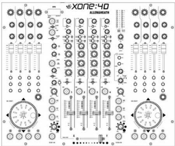
Xone:4D mixer
Check that the rear panel optical in/out blank plugs are fitted.
Safety Sheet
Important! Read this sheet before starting.
Retain for future reference.
natural_image
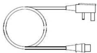
Simple line drawing of a cable with two connectors (no text or symbols)Mains Lead
Check that the correct mains plug is fitted.
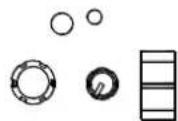
Spare knobs and buttons
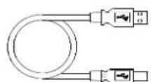
Type A-B USB Lead
To connect the Xone:4D to your computer.
natural_image
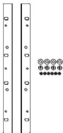
Pure electrical circuit lines without any symbolsRack Ears + fixings.
For mounting the 4D in a 19" rack.
6x M4x10mm screws
SOFTWARE INSTALLATION PC
STOP!
BEFORE YOU DO ANYTHING WITH YOUR XONE:4D, PLEASE READ THE FOLLOWING CAREFULLY TO ENSURE YOUR PC IS CORRECTLY SET UP TO BE USED WITH THE DEVICE. PLEASE DOWNLOAD THE LATEST DRIVERS FROM:
www.xone.co.uk/4d
Software Installation (Windows 2000, XP and Vista)
Follow the procedure described below to install the USB audio and MIDI drivers:
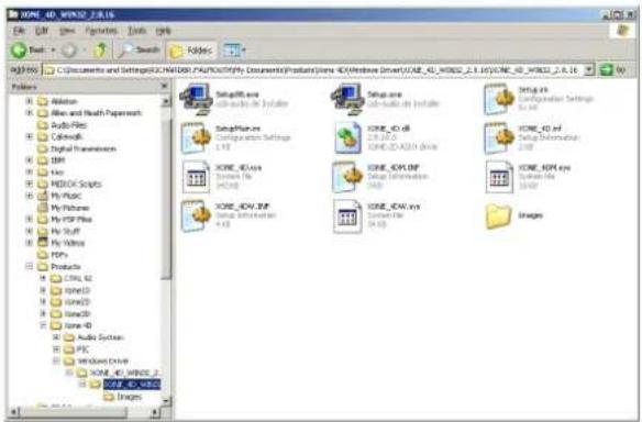
I— Using the provided power supply, connect the Xone:4D to your mains electricity supply.
Do not connect the 4D to the PC at this time.
2— Open the Drivers folder and run Setup.exe for Windows XP and Vista or Setup98.exe for Windows 98.
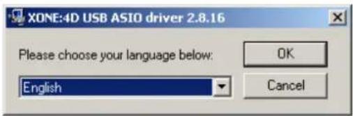
3— Select your preferred language
4— Select Install the driver
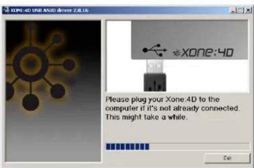
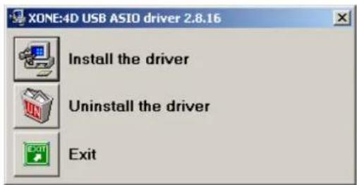
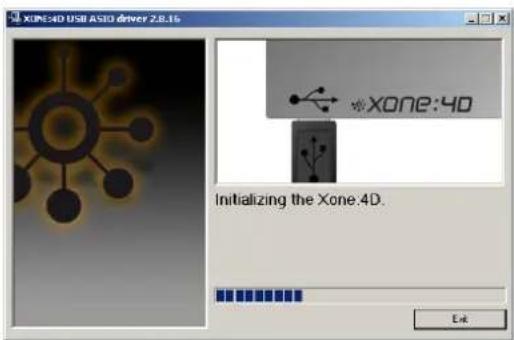
5— When prompted, connect the 4D to the PC with the USB lead.
The Xone:4D will now initialise.
SOFTWARE INSTALLATION PC
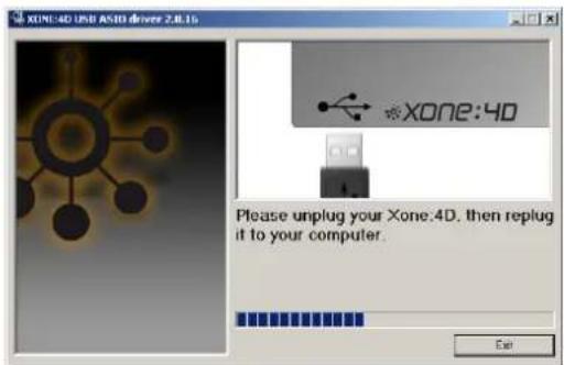
6— You will now be asked to unplug your Xone:4D
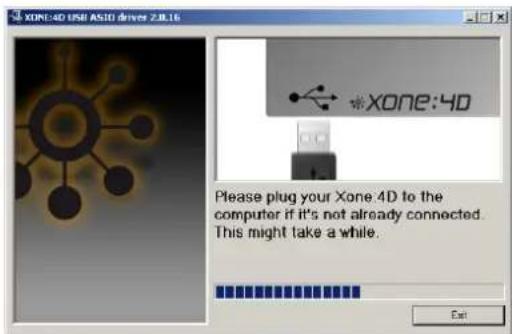
7— You will now be asked to plug in your Xone:4D again.
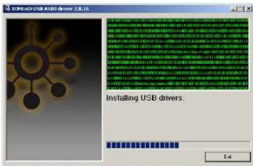
The USB drivers will now initialise.
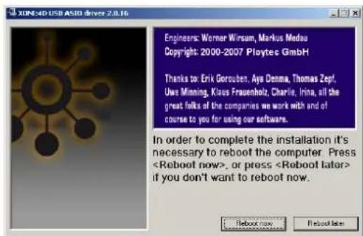
8— Once the driver installation is complete you will be prompted to reboot your computer.
Note: Always use the same USB port with your Xone:4D. When installing on a MS Windows system, the drivers will be associated with the USB port that you are currently plugged into. If you attempt to use the 4D with another USB port, or without installing the drivers at all, the system may work but with degraded performance (XP, Vista), or may not work at all (2000).
CHECKING THE DRIVER INSTALLATION—WINDOWS
Checking the Driver Installation
Once the driver installation is complete, you will need to check that the Xone:4D is being recognised. To do this, connect the Xone:4D to your PC/laptop and then right click on My Computer to open the System Properties window.
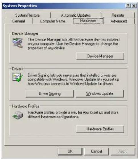
Select the Hardware tab then click on Device Manager
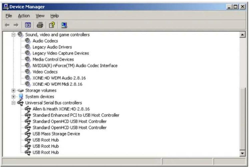
Expand the Sound, Video and Game Controllers section to reveal the WDM audio and MIDI drivers for the Xone:4D.
Expand the Universal Serial Bus Controllers section to reveal the Xone:4D ASIO driver and its release (version) number —in this case V2.8.16.
SOFTWARE INSTALLATION—APPLE MAC
STOP!
BEFORE YOU DO ANYTHING WITH YOUR XONE:4D, PLEASE READ THE FOLLOWING CAREFULLY TO ENSURE YOUR PC IS CORRECTLY SET UP TO BE USED WITH THE MIXER.
Mac OSX
Open the Xone_4D_Driver_x.x.x.dmg to reveal the window shown.
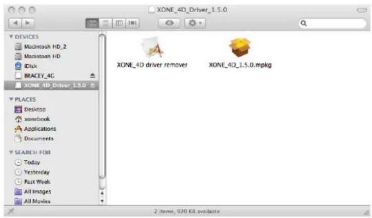
Click on the Xone:4D mpkg file to launch the driver installation.
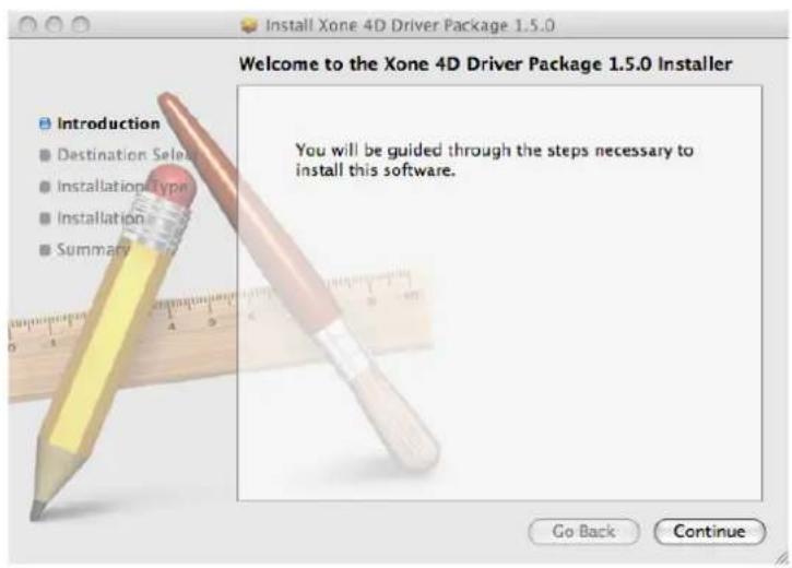
Click on "Continue".
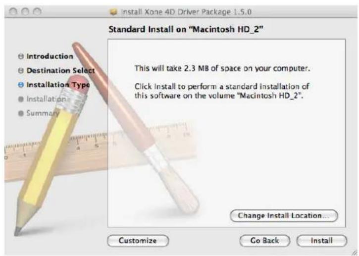
Select install location and then click "Install".
SOFTWARE INSTALLATION—APPLE MAC
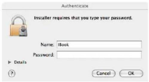
Enter your system password.
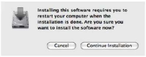
Click on "Continue Installation".
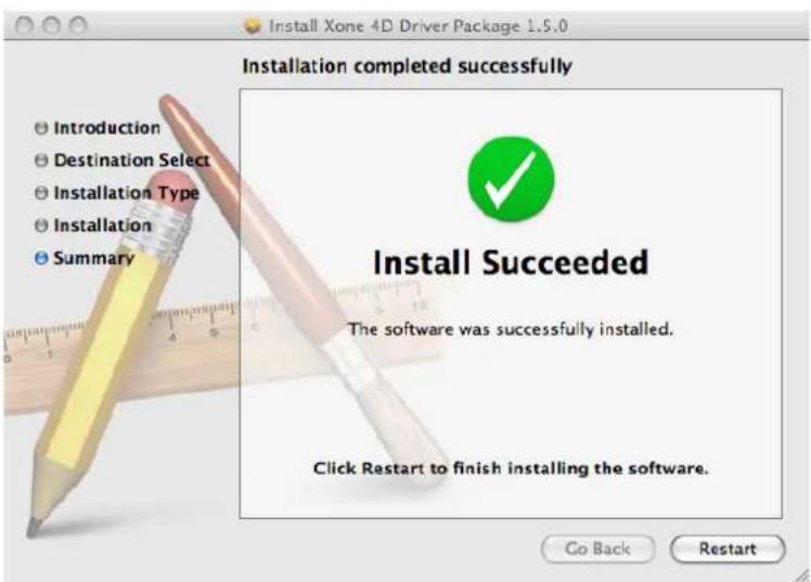
Restart your Mac.
CHECKING THE DRIVER INSTALLATION—APPLE MAC
Checking the Driver Installation
Once the driver installation is complete, you will need to check that the Xone:4D is being recognised. To do this, connect the Xone:4D to your Mac and then select:
Mackintosh HD
Applications
Utilities
Audio MIDI Setup
Now select the Audio tab and in the "Properties For" dropdown box select Allen & Heath Xone:4D.
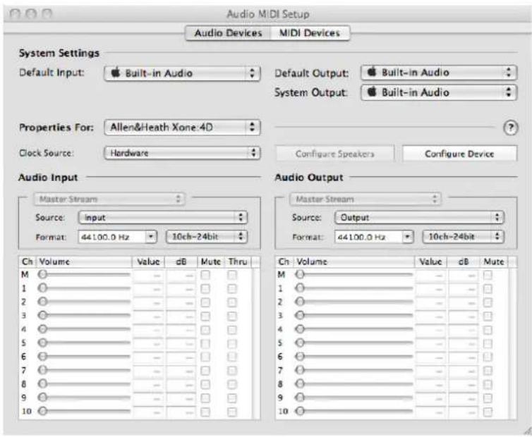
In the Audio Input section, the number of channels should be seen as 10, running at 24 bit.
In the Audio Output section, the number of channels should be seen as 10, running at 24 bit.
The sample rate is selectable from 44.1 to 96kHz.
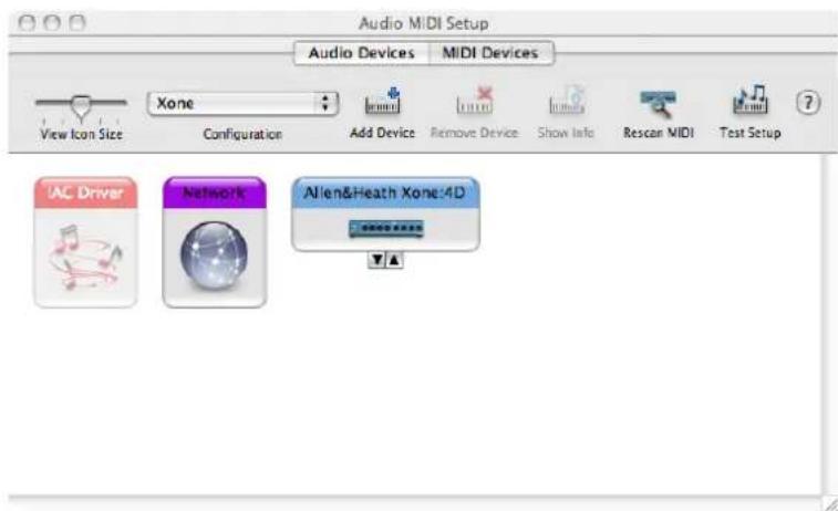
Now select the MIDI Devices tab and make sure that the Xone:4D is seen as a MIDI device as shown.
MIDI CHANNEL SETUP
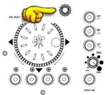
MIDI Channel Number
The MIDI channel number will default to channel 16, but can be changed to any channel between 1 and 16.
To change the MIDI channel number and MIDI map:
I. Hold down the switch on the encoder shown in the diagram
2. Turn on the Xone:4D
3. At the end of the start up sequence, when the illuminated switches have flashed three times, release the switch on the encoder.
The illuminated switches on the Xone:4D will display the current MIDI channel number in binary format as shown below.
Hot Setup
You may also enter setup mode by holding down the encoder shown above and then pressing the same encoder on the right hand MIDI pod. This allows the MIDI channel and Map to be changed if the mixer is in a fixed installation.
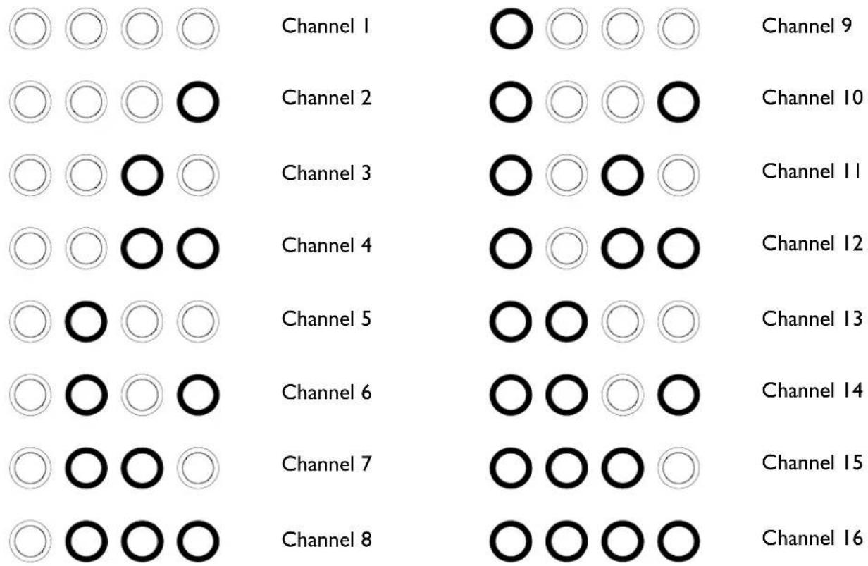
To change the channel number that the MIDI is transmitted on, rotate the encoder above the jog wheel.
Once the desired channel has been selected, press and then release the switch on the encoder above the jog wheel. The illuminated switches will flash once indicating that the channel number has been set.
Changing the MIDI Map
Once the MIDI channel number has been stored, the illuminated switch to the far right of the unit will flash indicating that the MIDI map may now be selected. The following examples are in relation to the left-hand MIDI pod on the Xone:4D.
Map I (Traktor default)
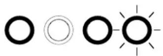
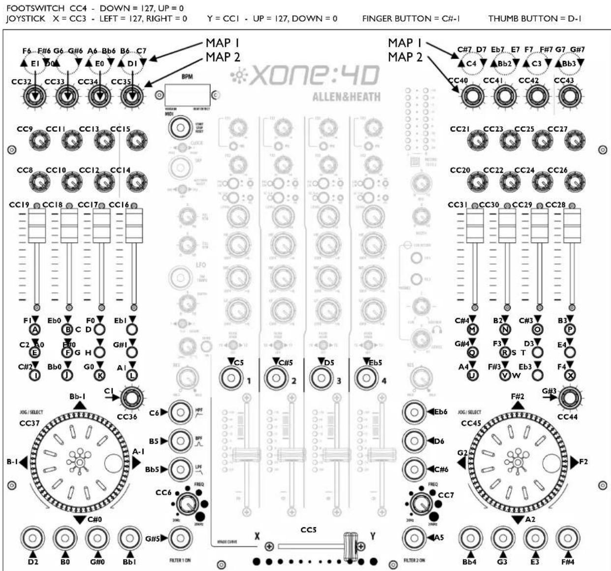
The first switch (far left) is used to select MIDI Map I. In this map the top row of encoders send 'Note On' messages upon rotation (see MIDI Control Section p39).
The third button (centre right) is used to determine the status of the light rings. If the third light ring is illuminated, then during normal operation all four light rings will stay illuminated at all times.
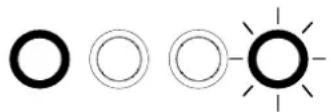
If the third light ring is not illuminated then each light ring will toggle on and off on receipt of a specific MIDI 'Note On' message. The 'Note On' message that the light ring responds to is the same 'Note On' message that is sent by the corresponding switch. Therefore, referencing the MIDI Control Section, the first (far left) light pipe will toggle on and off when it receives a 'Note On' message of DI.
Map 2 (Ableton default)
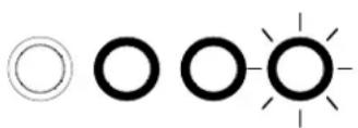
The second switch (centre left) is used to select MIDI Map 2. In this map the top row of encoders send 'Control Change' messages upon rotation (see MIDI Control Section p39).
The third button (centre right) is used to determine the status of the light rings. If the third light ring is illuminated, then during normal operation all four light rings will toggle on and off when their respective switch is pressed.
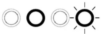
If the third light ring is not illuminated then each light ring will toggle on and off on receipt of a specific MIDI 'Note On' message. The 'Note On' message that the light ring responds to is the same 'Note On' message that is sent by the corresponding switch. Therefore, referencing the MIDI Control Section, the second (middle left) light pipe will toggle on and off when it receives a 'Note On' message of B-1.
When the desired MIDI map has been selected, press and release the switch on the encoder above the jog wheel. The illuminated switches will flash three times indicating that the MIDI map has been stored and that the unit is now in its normal operating mode.
SOUNDCARD ARCHITECTURE
ANALOGUE INPUTS:
The analogue inputs are sourced from the input channels on the Xone:4D as follows:
Channel Soundcard Input Selectable From
| 1 | 1/2 | Mic or Channel 1 (Pre or Post Fader) |
| 2 | 3/4 | FX2 or Channel 2 (Pre or Post Fader) |
| 3 | 5/6 | FX1 or Channel 3 (Pre or Post Fader) |
| 4 | 7/8 | Mix or Channel 4 (Pre or Post Fader) |
DIGITAL INPUTS:
The SPDIF digital inputs are sourced directly from the digital input sockets on the rear of the Xone:4D. The soundcard will internally switch between the COAX and Optical inputs, with the COAX connection being the default. The digital inputs are sent directly to the soundcard on inputs 9/10.
ANALOGUE OUTPUTS:
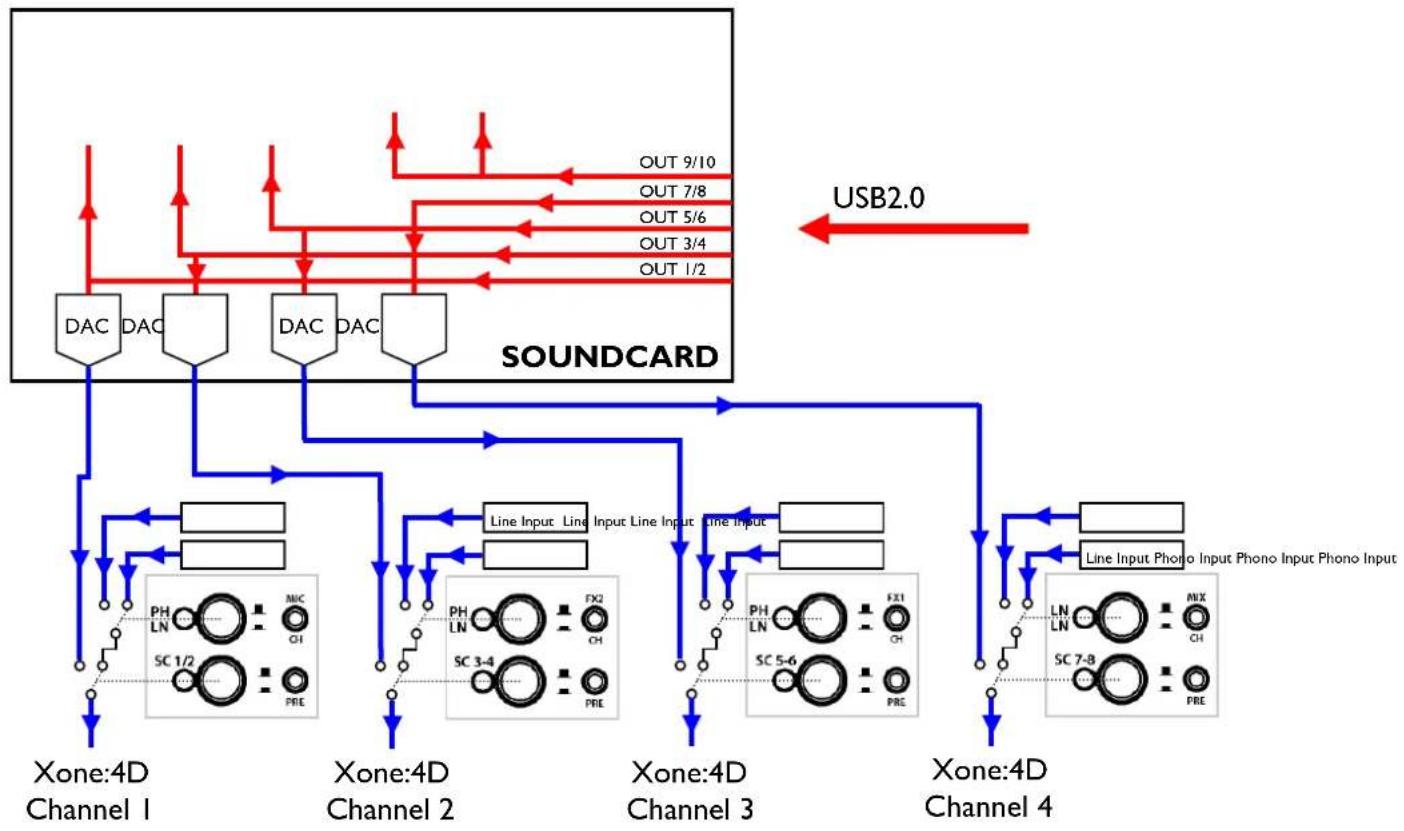
The analogue outputs are sent to the mixer from the PC/Mac and can be sourced as follows:
Channel Soundcard Output Routing
| 1 | 1/2 | Channel SCI-2 switch and rear panel |
| RCA connectors | ||
| 2 | 3/4 | Channel SC3-4 switch and rear panel |
| RCA connectors | ||
| 3 | 5/6 | Channel SC5-6 switch and rear panel |
| RCA connectors | ||
| 4 | 7/8 Channel SC7-8 switch |
DIGITAL OUTPUTS:
The SPDIF digital outputs are sent directly to the digital output sockets on the rear of the Xone:4D. The digital output will be present on both the COAX and Optical output connectors simultaneously. The digital outputs are sent directly from software on soundcard outputs 9/10.
SPDIF DIGITAL INPUTS AND OUTPUTS
SPDIF is a popular digital audio interfacing standard for connecting two channel (stereo) audio using a single COAX (RCA phono socket) or optical fibre (Toslink socket) cable.
The SPDIF inputs and outputs are available only when your computer is connected via the USB port. The computer provides the clocks needed for the soundcard to function.
Sample rates of up to 96kHz are supported.
SOFTWARE DESCRIPTION
The inputs and outputs of the soundcard have a description within the software being used. Below are the descriptions used in Ableton and Traktor.
Soundcard Input Ableton Descriptor Traktor Descriptor
1-2 1/2 (Stereo) IN 0-Allen&Heath Xone:4D 1 (Mono) & 2 (Mono) IN 1-Allen&Heath Xone:4D
3-4 3/4 (Stereo) IN 2-Allen&Heath Xone:4D 3 (Mono) & 4 (Mono) IN 3-Allen&Heath Xone:4D
5-6 5/6 (Stereo) IN 4-Allen&Heath Xone:4D 5 (Mono) & 6 (Mono) IN 5-Allen&Heath Xone:4D
7-8 7/8 (Stereo) IN 6-Allen&Heath Xone:4D 7 (Mono) & 8 (Mono) IN 7-Allen&Heath Xone:4D
9-10 (Digital in 1-2) 9/10 (Stereo) IN 8-Allen&Heath Xone:4D 9 (Mono) & 10(Mono) IN 9-Allen&Heath Xone:4D
Soundcard Output Ableton Descriptor Traktor Descriptor
1-2 1/2 (Stereo) OUT 0-Allen&Heath Xone:4D 1 (Mono) & 2 (Mono) OUT 1-Allen&Heath Xone:4D
3-4 3/4 (Stereo) OUT 2-Allen&Heath Xone:4D 3 (Mono) & 4 (Mono) OUT 3-Allen&Heath Xone:4D
5-6 5/6 (Stereo) OUT 4-Allen&Heath Xone:4D 5 (Mono) & 6 (Mono) OUT 5-Allen&Heath Xone:4D
7-8 7/8 (Stereo) OUT 6-Allen&Heath Xone:4D 7 (Mono) & 8 (Mono) OUT 7-Allen&Heath Xone:4D
9-10 (Digital Out 3-4) 9/10 (Stereo) OUT 8-Allen&Heath Xone:4D 9 (Mono) & 10 (Mono) OUT 9-Allen&Heath Xone:4D
Supported Buffer Sizes
The Xone:4D supports the following buffer sizes:
64, 96, 128, 192, 256, 384, 512, 768, 1024 etc.
ABLETON SET UP
Turn on your Xone:4D, launch your Ableton software and open the Preferences window.
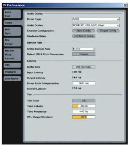
I— In the Preferences window select the Audio tab. Change the driver type to ASIO and set the Audio Device to Xone:4D USB ASIO driver
In the Settings section click on the Input Config button.
2— Select the Stereo options and de-select the Mono options. You must click OK for the changes to take effect.
Now, in the Settings section of the Audio tab, click on the Output Config button.
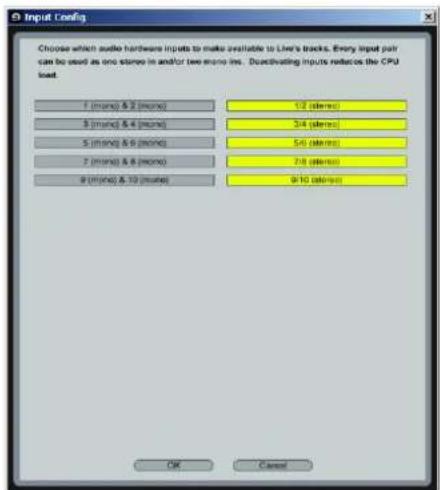
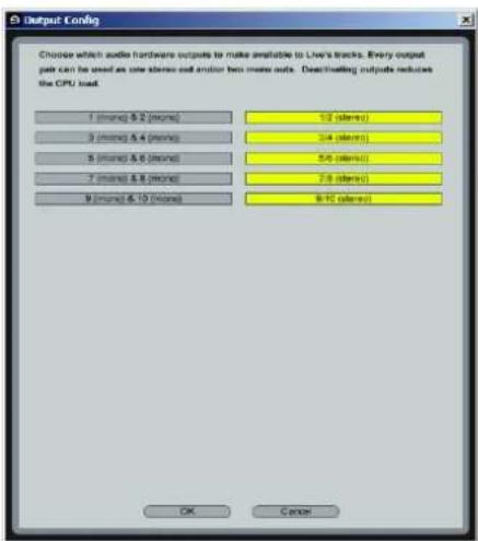
3—Select the Stereo options and de-select the Mono options. You must click OK for the changes to take effect.
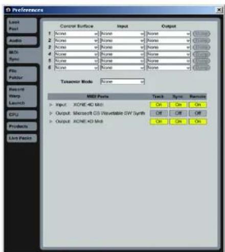
Now select the MIDI Sync tab of the Preferences window.
4— Set the Track, Sync and Remote to On for the Xone:4D MIDI Input and Output.
TRAKTOR SET UP
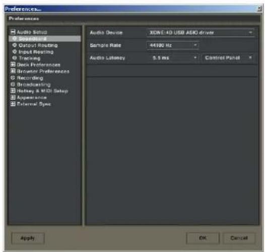
Turn on your Xone:4D, launch your Traktor software and open the Preferences window.
2— In the Input Routing section, assign the Xone:4D analogue or digital inputs to the required deck.
Now select Output Routing.
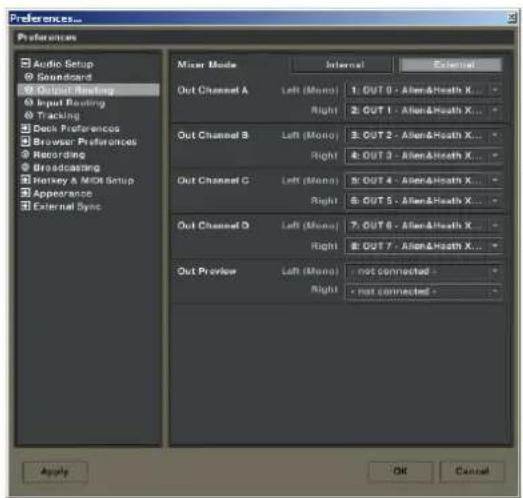
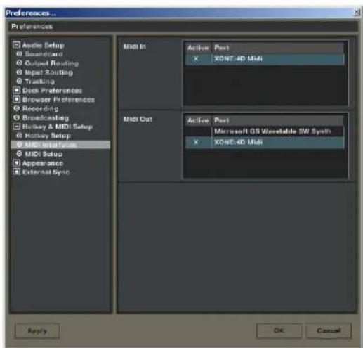
4— In the Preferences window expand the Hotkey & MIDI Setup section, select MIDI Interfaces, double click the Active box next the Xone:4D MIDI and an X will appear. This will activate the MIDI from the Xone:4D.
I— In the Preferences window, expand the Audio Setup section and select Soundcard. Set the Audio Device to Xone:4D USB ASIO driver'
Now select Input Routing.
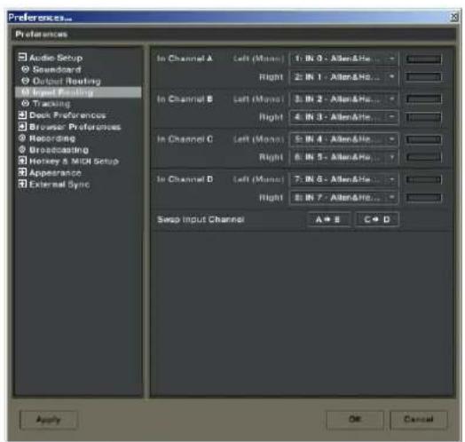
3— In the Output Routing section, first make sure that the Mixer Mode is set to External. Now assign the Xone:4D analogue or digital outputs to the required deck.
PANEL DRAWINGS

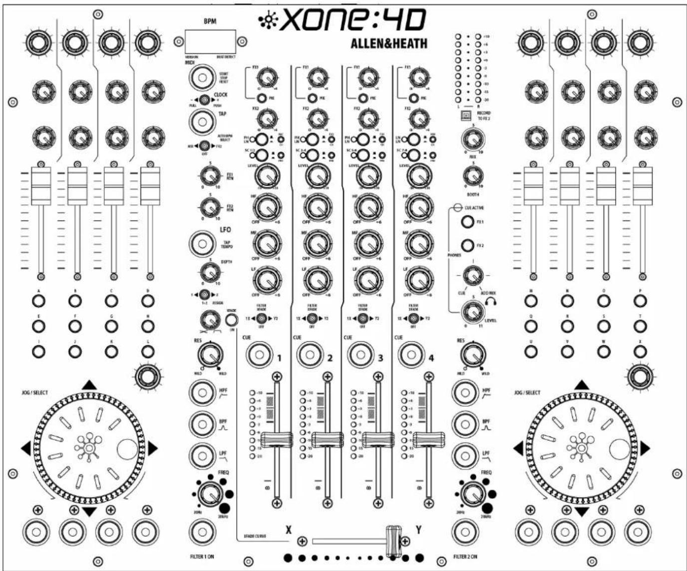
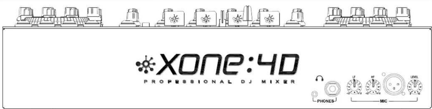
INTRODUCTION TO THE XONE:4D
Welcome to the Allen & Heath Xone:4D digital DJ workstation. This system has been designed with the help of some of the world's most cutting edge DJs to provide a seamless integration of traditional and computer-based audio replay systems. The Xone:4D comprises three main sections:
MIXER— The mixer is based on the award-winning Allen & Heath Xone:92. It lets you mix a combination of vinyl, CD and other sources through 4 stereo channels to its main mix and monitor outputs. It provides 2 effects send/return loops, 3-band EQ isolators, 2 analogue VCF filters with LFO, VCA crossfader and channel faders, DJ mic and cue monitoring system. A BPM counter can be set for tap tempo or automatic beat detection.
MIDI CONTROLLER— Two dedicated control strips provide a total of 105 MIDI messages from a combination of switches, rotary and fader controls, multi-function jog wheels, foot pedal and game controllers. A MIDI shift mode allows all of the controls to be mapped for a second time, giving the MIDI surface a second 'page'. A fader pick-up algorithm has been incorporated into the mixer allowing seamless integration of the pages. In addition, several mixer functions generate and respond to MIDI, and the BPM counter provides MIDI start/stop and clock. The Xone:4D provides full control of external MIDI devices including the most sophisticated DJ performance computer environments. Overlays are available to identify the control function for popular software applications.
SOUNDCARD— A high performance 20-channel USB2.0 soundcard is built into the mixer. The soundcard features 4 analogue stereo inputs and four analogue stereo outputs, transmitting audio at 96kHz with 24 bit resolution. It uses USB to interface the mixer audio and MIDI to a PC where the sound may be manipulated in real time using one of the several exciting new DJ performance applications. The soundcard also produces SPDIF COAX and optical digital inputs and outputs. A low latency ASIO driver is provided for audio streaming between mixer and PC.
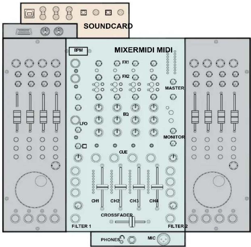
MIXER
Each of the 4 channels can select one of 3 sources: phono, line or soundcard audio as shown. RIAA phono preamps are available on channels 1, 2 and 3. These may be changed to line input by resetting an internal jumper link if required. Level may be adjusted over a +/- 10dB range if the signal reads too high or low on the channel meters. The 3-band EQ provides a safe amount of boost but full cut (kill) for dramatic effect. A mic input with level and 2-band EQ routes direct to the main mix. The DJ cues the mix using headphones. The mix may be added to the cue'd channel signal to help the DJ synchronise the beat.
FILTERS
The channel signal may be routed direct to the LR mix or through either of the two analogue filters. These provide the characteristic Allen & Heath analogue filter sound with combinations of 3 switched bands, swept frequency, resonance and tap tempo LFO control. The VCA crossfader affects the filter path when switched in.
FX LOOPS
Two FX sends are provided. FX1 may be switched pre or post fader, while FX2 is pre fader. The send is typically connected to an effects device or sampler, then routed back to the mix via one of the two FX return inputs.
OUTPUTS
The balanced XLR mix output feeds the house sound system. The monitor output follows the main mix and can provide a booth monitor, alternative zone or recording feed.
BPM COUNTER
Displays the BPM (beats per minute) of a music track entered manually by tapping a button in time to the music, or automatically by analysing the signal routed to it. The signal may be routed from the main mix or from an individual channel via the pre-fade FX2 mix so that the beat may be calculated and checked before the track is routed to the mix.
The BPM counter outputs MIDI clock so that a slave device such as a hardware or software sequencer can be synchronized to the timing of a track playing through the Xone:4D. To aid synchronization the MIDI clock can be momentarily speeded up or slowed down by operating the PUSH/PULL lever.
UV REACTIVE PAINT
The white artwork on the front panel of the Xone:4D uses a UV reactive layer and will therefore glow under UV light to improve visibility in low level light conditions.
MIDI CONTROL
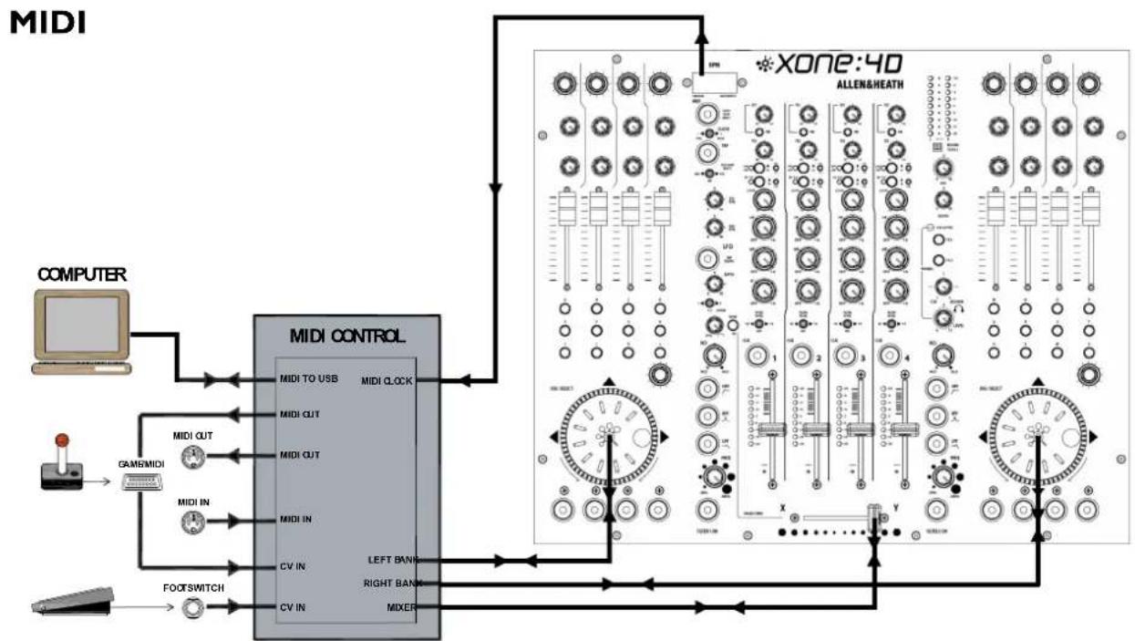
MIDI (musical instrument digital interface) is a standardised protocol for communication between electronic music devices as well as between those devices and computers. Two identical banks of MIDI controls are provided on either side of the mixer section. These bring control of remote performance equipment such as computer-based sound manipulation and sequencing, samplers, effects and even lighting right to the mixer control surface. The function of the controls may be identified using overlay sheets, samples of which are supplied with the Xone:4D.
The control banks comprise both linear and rotary faders, rotary encoders with integrated switches, push button switches with and without light ring indicators, and large dedicated jog wheels with four position switches. A footswitch socket and the 15-pin Game port provide control voltage input, which produce further MIDI output from foot pedal, joystick and custom-wired controllers. Operation of these controls does not affect any audio signals directly, but is automatically translated into MIDI messages according to a pre-configured MIDI 'map'. The MIDI channel number, map and other functions are selected during the start-up configuration procedure. Two MIDI maps are available to suit the various performance software applications currently available. Further details are provided later in this guide.
In addition to the dedicated MIDI controls, some of the DJ mixer functions also output MIDI messages when operated. These include all switches with light rings, the filter frequency controls, the crossfader, and BPM start/stop and clock. The MIDI data is sent out of the mixer via the rear panel MIDI out and Game port sockets, and is simultaneously transferred to a connected computer via the USB interface. The MIDI surface has two 'pages', allowing all of the MIDI controls (with the exception of the crossfader), to be mapped twice.
SOUNDCARD
The 20-channel USB2.0 soundcard is built into the mixer to ensure the highest performance and lowest noise. 24-bit converters are used at a maximum sampling rate of 96kHz, together with low latency ASIO drivers supplied by Allen & Heath.
There are 4 stereo (8 mono) analogue and 1 stereo (2 mono) digital inputs to the PC/Mac from the Xone:4D, and 4 stereo (8 mono) analogue and 1 stereo (2 mono) digital outputs from the PC/Mac to the Xone:4D.
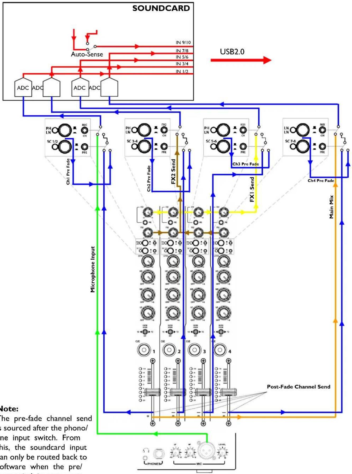
The soundcard input block diagram is shown overleaf.
SOUNDCARD INPUT BLOCK DIAGRAM
flowchart
graph TD
    A["SOUNDCARD"] --> B["Auto-Sense"]
    B --> C["ADC ADC"]
    B --> D["ADC ADC"]
    B --> E["ADC ADC"]
    C --> F["USB2.0"]
    D --> F
    E --> F
    F --> G["Ch1 Pre Fade"]
    G --> H["Microphone Input"]
    H --> I["Post-Fade Channel Send"]
    I --> J["Main Mix"]
    J --> K["Ch3 Pre Fade"]
    K --> L["FX1 Send"]
    L --> M["Ch4 Pre Fade"]
    M --> N["Post-Fade Channel Send"]
    N --> O["Post-Fade Channel Send"]
    O --> P["Post-Fade Channel Send"]
    P --> Q["Post-Fade Channel Send"]
    Q --> R["Post-Fade Channel Send"]
    R --> S["Post-Fade Channel Send"]
    S --> T["Post-Fade Channel Send"]
    T --> U["Post-Fade Channel Send"]
    U --> V["Post-Fade Channel Send"]
    V --> W["Post-Fade Channel Send"]
    W --> X["Post-Fade Channel Send"]
    X --> Y["Post-Fade Channel Send"]
    Y --> Z["Post-Fade Channel Send"]
    Z --> AA["Post-Fade Channel Send"]
    AA --> AB["Post-Fade Channel Send"]
    AB --> AC["Post-Fade Channel Send"]
    AC --> AD["Post-Fade Channel Send"]
    AD --> AE["Post-Fade Channel Send"]
    AE --> AF["Post-Fade Channel Send"]
    AF --> AG["Post-Fade Channel Send"]
    AG --> AH["Post-Fade Channel Send"]
    AH --> AI["Post-Fade Channel Send"]
    AI --> AJ["Post-Fade Channel Send"]
    AJ --> AK["Post-Fade Channel Send"]
    AK --> AL["Post-Fade Channel Send"]
    AL --> AM["Post-Fade Channel Send"]
    AM --> AN["Post-Fade Channel Send"]
    AN --> AO["Post-Fade Channel Send"]
    AO --> AP["Post-Fade Channel Send"]
    AP --> AQ["Post-Fade Channel Send"]
    AQ --> AR["Post-Fade Channel Send"]
    AR --> AS["Post-Fade Channel Send"]
    AS --> AT["Post-Fade Channel Send"]
    AT --> AU["Post-Fade Channel Send"]
    AU --> AV["Post-Fade Channel Send"]
    AV --> AW["Post-Fade Channel Send"]
    AW --> AX["Post-Fade Channel Send"]
    AX --> AY["Post-Fade Channel Send"]
    AY --> AZ["Post-Fade Channel Send"]
    AZ --> BA["Post-Fade Channel Send"]
    BA --> BB["Post-Fade Channel Send"]
    BB --> BC["Post-Fade Channel Send"]
    BC --> BD["Post-Fade Channel Send"]
    BD --> BE["Post-Fade Channel Send"]
    BE --> BF["Post-Fade Channel Send"]
    BF --> BG["Post-Fade Channel Send"]
    BG --> BH["Post-Fade Channel Send"]
    BH --> BI["Post-Fade Channel Send"]
    BI --> BJ["Post-Fade Channel Send"]
    BJ --> BK["Post-Fade Channel Send"]
    BK --> BL["Post-Fade Channel Send"]
    BL --> BM["Post-Fade Channel Send"]
    BM --> BN["Post-Fade Channel Send"]
    BN --> BO["Post-Fade Channel Send"]
    BO --> BP["Post-Fade Channel Send"]
    BP --> BQ["Post-Fade Channel Send"]
    BQ --> BR["Post-Fade Channel Send"]
    BR --> BS["Post-Fade Channel Send"]
    BS --> BT["Post-Fade Channel Send"]
    BT --> BU["Post-Fade Channel Send"]
    BU --> BV["Post-Fade Channel Send"]
    BV --> BW["Post-Fade Channel Send"]
    BW --> BX["Post-Fade Channel Send"]
    BX --> BY["Post-Fade Channel Send"]
    BY --> BZ["Post-Fade Channel Send"]
    BZ --> CA["Post-Fade Channel Send"]
    CA --> CB["Post-Fade Channel Send"]
    CB --> CC["Post-Fade Channel Send"]
    CC --> CD["Post-Fade Channel Send"]
    CD --> CE["Post-Fade Channel Send"]
    CE --> CF["Post-Fade Channel Send"]
    CF --> CG["Post-Fade Channel Send"]
    CG --> CH["Post-Fade Channel Send"]
    CH --> CI["Post-Fade Channel Send"]
    CI --> CJ["Post-Fade Channel Send"]
    CJ --> CK["Post-Fade Channel Send"]
    CK --> CL["Post-Fade Channel Send"]
    CL --> CM["Post-Fade Channel Send"]
    CM --> CN["Post-Fade Channel Send"]
    CN --> CO["Post-Fade Channel Send"]
    CO --> CP["Post-Fade Channel Send"]
    CP --> CQ["Post-Fade Channel Send"]
    CQ --> CR["Post-Fade Channel Send"]
    CR --> CS["Post-Fade Channel Send"]
    CS --> CT["Post-Fade Channel Send"]
    CT --> CU
    CU --> CV
    CV --> CW
    CW --> CX
    CX --> CY
    CY --> CZ
    CZ --> DA
    DA --> DB
    DB --> DC
    DC --> DD
    DD --> DE
    DE --> DF
    DF --> DG
    DG --> DH
    DH --> DI
    DI --> DJ
    DJ --> DK
    DK --> DL
    DL --> DV
    DV --> DW
    DW --> DX
    DX --> DXB
    DXB --> DXC
Note:
The pre-fade channel send is sourced after the phono/ line input switch. From this, the soundcard input can only be routed back to software when the pre/post switch is set to post.
SOUNDCARD OUTPUT / MIDI BLOCK DIAGRAM
SOUNDCARD
flowchart
graph TD
    subgraph SOUNDCARD
        direction TB
        A1["DAC DAC"] --> B1["Blue Input"]
        A2["DAC DAC"] --> B2["Blue Input"]
        A3["DAC DAC"] --> B3["Blue Input"]
        B1 --> C1["Xone:4D Channel 1"]
        B2 --> C2["Xone:4D Channel 2"]
        B3 --> C3["Xone:4D Channel 3"]
        C1 --> D1["PH LN MIC CI PRE"]
        C2 --> D2["PH LN FX2 CH SC 1/2"]
        C3 --> D3["PH LN FX1 CH SC 3-4"]
        C1 --> E1["Line Input Line Input Line Input"]
        C2 --> E2["Line Input Line Input Line Input"]
        C3 --> E3["Line Input Line Input Line Input"]
        E1 --> F1["Line Input Phono Input Phono Input Phono Input"]
        E2 --> F2["Line Input Phono Input Phono Input Phono Input"]
        E3 --> F3["Line Input Phono Input Phono Input Phono Input"]
    end
    SOUNDCARD -->|USB2.0| Output
    style SOUNDCARD fill:#f9f,stroke:#333
flowchart
graph TD
    A["COMPUTER"] --> B["MIDI CONTROL"]
    C["GAM/MIDI"] --> B
    D["FOOT/SWITCH"] --> B
    B --> E["MIDI TO USB"]
    B --> F["MIDI CLOCK"]
    B --> G["MIDI CUT"]
    B --> H["MIDI CUT"]
    B --> I["MIDI IN"]
    B --> J["MIDI IN"]
    B --> K["CV IN"]
    B --> L["CV IN"]
    B --> M["LEFT BANK"]
    B --> N["RIGHT BANK"]
    B --> O["MIXER"]
    P["XONE:4D ALLEN&HEATH"] --> Q["ALLEN & HEATH Module"]
    Q --> R["Computer"]
MIXER SECTION — CHANNEL INPUT
flowchart
graph TD
    A["FX1"] --> B["PRE"]
    C["FX2"] --> D["ON"]
    E["2"] --> F["SC 7-8"]
    G["LEVEL"] --> H["-10"]
    I["HF"] --> J["OFF"]
    K["MF"] --> L["OFF"]
    M["LF"] --> N["OFF"]
    O["FILTER XFADE"] --> P["1X"]
    Q["OFF"] --> R["Y2"]
|
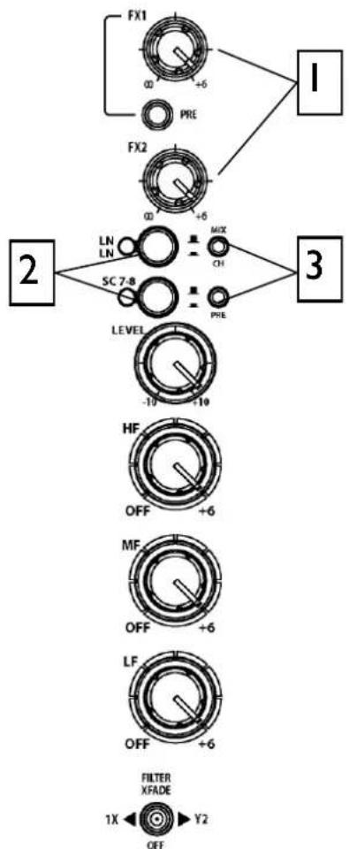
FX I-2 send controls
These controls adjust the signal level that is sent from each channel to the two FX mix busses. These signals will appear at the RCA sockets on the rear of the unit.
FXI PRE switch determines whether the FXI send signal is affected by the channel fader. When pressed the signal is pre-fader, when released post-fader.
FXI can also be sent to the input of the soundcard for processing or recording by the PC (see Soundcard Mode for details).
FX2 is pre-fader (this can be changed internally - see User Options). FX2 can also be selected as the audio source for the Auto Beat detector (See BPM Detector).
2
Input Selection
Two switches select one of three possible stereo audio sources; Line A (RIAA phono on CH I-3), Line B, or output from the computer via the internal soundcard (SCI-6). Switch 2 (SC) overrides switch I (phono/line). The LED indicator displays which source is active:
CH1 CH2 CH3 CH4
Soundcard Input Selection Switches
Two switches select one of three possible soundcard input sources. All channels have the option of pre or post channel fader sends as well as the microphone input, FX1 bus, FX2 bus and main mix. The selector switches are set up as follows:
| Ch | Switch 1 | Switch 2 |
| 1 | Mic / Channel | Pre / Post fader |
| 2 | FX2 / Channel | Pre / Post fader |
| 3 | FX1 / Channel | Pre / Post fader |
| 4 | Mix / Channel | Pre / Post fader |
MIXER SECTION — CHANNEL INPUT

Channel Level Control
This control has a range of +/- 10dB either side of the 0dB centre position. Use it to adjust the signal level of an audio source to give a nominal 0dB reading on the channel meter, with the peak level at or below +6dB. Turn LEVEL down if the +10 peak meter starts flashing.
Channel Equalizer/Isolator
The Xone:4D is equipped with a very powerful 3 band EQ stage providing a controlled +6dB of boost when fully clockwise but full isolation (cut) of each band for dramatic effect when fully anticlockwise. Centre frequencies are set at:
$$ \mathrm{HF} = 1 0 \mathrm{kHz} (\text { high frequency, treble }) $$
$$ \mathrm{MF} = 1. 2 \mathrm{kHz} (\text { mid frequency }) $$
$$ \mathrm{LF} = 1 2 0 \mathrm{Hz} (\text { low frequency, bass }) $$
Filter/Crossfade Assignment
The channel signal can be routed directly to the main mix or via either of the two filter/crossfade paths. Note that the crossfade affects the filter path only.
Set the 3-position switch to its mid position to route the signal direct to the mix, or to its left or right positions to route the signal to filter-1/crossfade-X or filter-2/crossfade-Y respectively.
To enable the crossfader check that the XFADE ON switch above the filter1 controls is pressed.
Cue Switch
Press the cue switch to listen to the channel pre-fade signal in the headphones and see its level on the main meters. The LED indicator ring around the switch lights up when selected. The big red CUE ACTIVE indicator also lights to warn that you are monitoring the channel signal rather than the main mix.
Press the switch to deselect cue. The switches are interlocked; pressing another one turns off the previous selection.
MIXER SECTION — CHANNEL INPUT

Channel Meter
Displays the channel signal level. It is post-EQ and pre-fader. This means it is not affected by the EQ or fader position.
The channel level control should be set so that the meter averages around '0' with loudest peaks no higher than '+6'. Turn down the level control if the +10 peak indicator lights.
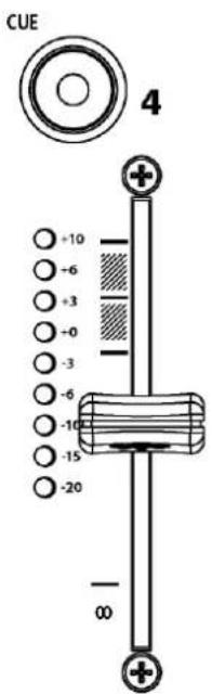
Channel Fader
A high quality, smooth travel dual-rail fader adjusts the channel signal level from fully off to fully on.
MIXER SECTION — MIX AND MONITOR
Mix / Monitor Meters
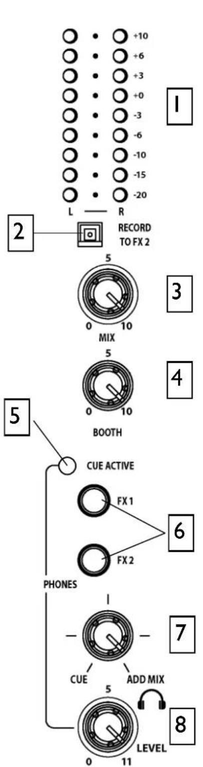
The main meters follow the selected monitor source. The meter reads '0' for an XLR output of +4dBu. The mixer should be operated with these meters averaging around '0' with loudest peaks no higher than '+6'.
Record to FX2 Switch
Selecting this switch will send the pre-fade mix output to the FX2 Send RCA sockets on the rear of the mixer.
The mix signal is switched after the internal FX2 buss, allowing the FX2 Send controls to still be used for software effect loops and a source for the BPM counter.
Mix Master Level Control
A rotary master control adjusts the level of the main mix XLR outputs feeding the house sound system. This does not affect the monitor output or the meter reading.
4 Monitor Master Level Control
Adjusts the level of the signal to the stereo monitor RCA output. This does not affect the headphones. The monitor output could be used for a booth monitor, recording or an additional zone feed.
Cue Active LED
A large red LED indicator lights when a channel CUE is active. This indicates that the selected channel CUE signal is heard in the headphones and displayed on the monitor meters.
Monitor Select Switches
In the normal 'up' position the headphones and meters monitor the pre-level main mix. Press these switches to select either of the stereo FX mixes as the headphones and meter source. Note that this does not affect the main mix or monitor outputs.
MIXER SECTION — MIX AND MONITOR
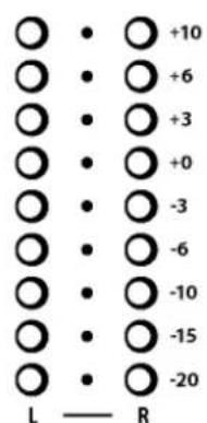
Allows the main mix output to be added to the CUE signal. Turned fully anti-clockwise, only the active CUE signal is heard through the headphones when selected. Gradually turning clockwise introduces the main mix output to the headphones, adding to the active CUE. This does not affect the meters.
Headphones Level Control
Adjusts the level of the headphones signal.
Warning! To avoid damage to your hearing do not operate the headphones or sound system at excessively high volume. Continued exposure to high volume sound can cause frequency selective or wide range hearing loss.
MIXER SECTION — FILTERS and LFO
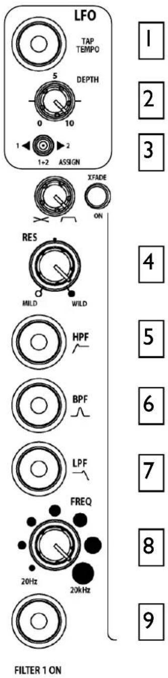
LFO Tap Tempo button
Tap the tap tempo button in time with the beat to set the frequency of the LFO.
2 LFO Depth control
When assigned, the LFO modulates the filter with a cyclic frequency sweep effect in time to the beat set using the tap tempo button. The depth control adjusts how much effect the LFO has on the filter effect from fully off to very deep. For more information, including the LFO editor function, see page 37.
LFO Filter Assign Switch
Use this switch to assign the LFO to either or both the filters.
Resonance Control
This produces the classic analogue VCF sound by feeding some of the filter output back to its input. The control ranges from 'mild' producing a very subtle effect, to 'wild' producing a dramatic phase effect with feedback just short of oscillation.
HPF Button
Turns on the high pass (bass cut) filter slope. The light ring around the button illuminates when selected.
BPF Button
Turns on the band pass (bell shaped) filter slope. The light ring around the button illuminates when selected.
LPF Button
Turns on the low pass (treble cut) filter slope. The light ring around the button illuminates when selected.
Frequency Sweep Control
This control sets the -3dB cut-off frequency of the filter. It ranges from very low frequency (20Hz) to very high (20kHz).
Filter On Switch
Switches the filter on and off. The light ring around the button illuminates when the filter is active.
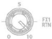
These controls route the incoming signal from the stereo FX1 and FX2 Return RCA connectors on the rear panel to the mix. They adjust how much return signal is added to the mix.
Crossfader
This lets you fade between signals routed to either side, typically to fade smoothly into a new music track or to creatively layer sounds when scratch or cut mixing.
The crossfader is a VCA controller, which affects the level of signals routed via the filters. Make sure the toggle switches on the channels you wish to fade are set to X or Y as appropriate.
Please contact your Allen and Heath approved service centre for crossfader service or replacement.
Xfade on switch
Press this switch to activate the crossfader.
XFade Curve Control
This control adjusts the crossfader curve between dipped response, ideal for seamless beat mixing and fast-attack, suitable for scratch or cut mixing.
FRONT CONTROLS & CONNECTORS
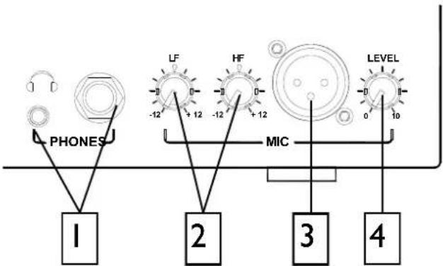

Headphones Outputs
Stereo 1/4" TRS jack and 3.5mm mini-jack. Plug in good quality stereo headphones intended for DJ monitoring. Use closed-ear headphones that provide maximum acoustic isolation when cueing your sources. We recommend that you use high quality headphones rated between 30 to 100 ohms impedance. 8 ohm headphones are not recommended.

Mic EQ Controls
The MIC equaliser provides a tool to adjust the tonal quality of the sound to correct source problems such as microphone response, proximity effect, noise and feedback, to help the voice cut through the mix, or to adjust the overall 'feel'. Start with the EQ controls set to their mid (flat) position, then adjust to achieve the desired sound.

Mic Input
Balanced XLR. Plug in a DJ, guest or announcement microphone here. Use a good quality low impedance dynamic mic such as those specifically designed for vocals. Do not use high impedance or unbalanced microphones, or condenser types which require phantom power. Use the best professional grade balanced cables and connectors you can afford, as these are typically subject to intense use and abuse in the club environment.

Mic Level Control
Adjusts the input sensitivity of the Mic channel to match the connected source to the console's 0dB operating level.
When the Mic channel is not in use, always turn the level control fully anti-clockwise to prevent unwanted noise from this sensitive input entering the main Mix.
REAR CONNECTORS
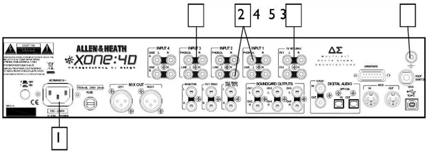

AC Mains Input
IEC cable with moulded mains plug suitable for your local supply.
Important: Read the SAFETY INSTRUCTIONS sheet included with the Xone:4D and printed on the rear panel.
Check that the correct mains lead with moulded plug has been supplied with your console. The power supply accepts mains voltages within the range 100-240V without changing any fuses or settings.
Ensure that the IEC mains plug is pressed fully into the rear panel socket before switching on.
Note: It is standard practice to turn connected power amplifiers down or off before switching the console on or off. This prevents any audible switch-on thumps.

FXI-2 Line Return Input
RCA phono.
Connect stereo line level sources such as the return signal from external effects units. These inputs are routed directly to the main mix as the default setting, but this can be changed internally to send them to the Filters and crossfader (see User Options)

CHI-4 Stereo Line Input
RCA phono.
Connect stereo line level music sources such as CD, MD, DAT, drum machines, keyboards or other instruments. Do not connect turntables which require RIAA equalisation. Alternatively, you can connect to jack sources using a cable with RCA to jack adapters. Avoid using low grade cables such as those often supplied with domestic equipment as these can quickly prove unreliable in use.

CHI-3 Stereo Phono Input
RCA phono.
Plug in turntables with magnetic cartridges requiring RIAA equalisation. For non-RIAA turntables plug into the LINE input instead. Do not plug in line level sources to the phono inputs as these will overload the preamp and cause severe high level distortion.

Chassis Earth Terminal
A screw terminal is provided for connecting the earth straps from turntables. This connection earths the metal parts of the turntable to reduce hum, buzz or similar audible noise getting into the system.
REAR CONNECTORS
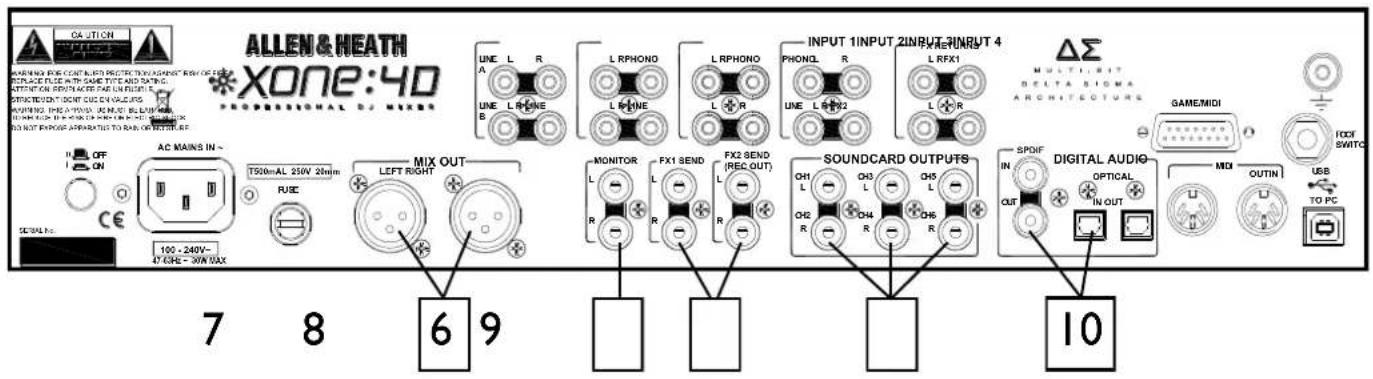
Mix Output
Balanced XLR. This is the main output that feeds the house PA system. Plug into the house processor/amplifier system using balanced cables. Use balanced cables and equipment.

Monitor Output
RCA phono. Provides a line level stereo feed to the DJ local monitor amplifier system. It is not affected by the master fader or cue system.
Can also be used as an alternative zone or record output.

FXI-2 Send Output
RCA phono. Depending on the application of the FX mix, these stereo line level outputs can be used to feed samplers and other effects units, an additional monitor, zone or recorder.
The FX2 Send RCA connectors can also be switched on the front panel to provide a record output (see page 26).

Soundcard Outputs
RCA phono.
Outputs from the internal soundcard. These are always available irrespective of the source selection on the stereo channels. These outputs could be fed to an additional mixer or processor before being brought back into the mix.
Depending on the soundcard operating mode, signals are available on sockets 1-6 or 1-4.

SPDIF DIGITAL INPUTS AND OUTPUTS
SPDIF is a popular digital audio interfacing standard for connecting two channel (stereo) audio using a single COAX (RCA phono socket) or optical fibre (Toslink socket) cable.
For reliable connection use a 75 ohm COAX cable intended for this function. Avoid the use of cheap audio cables. Use purpose made optical fibre cables for connection using the Toslink port. Make sure the blanking plugs provided are fitted to any unused Toslink sockets.
The SPDIF inputs and outputs are available only when your computer is connected via the USB port. The computer provides the clocks needed for the soundcard to function.
Sample rates ranging from 44.1 to 96kHz are supported.
REAR CONNECTORS
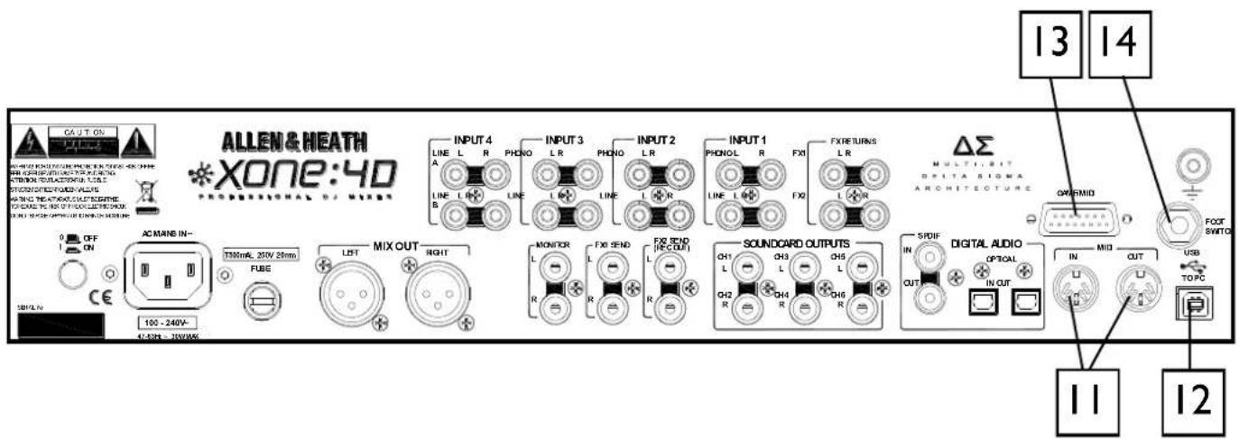

MIDI Input / Output
5 pin DIN socket.
Connect to either a MIDI interface or directly to MIDI compatible equipment using a standard 5 pin DIN (MIDI) lead. The MIDI output socket data duplicates what is sent via the USB connection to the PC, and to the gameport.
MIDI in can be used to remotely control the status of all switches that have associated LED light rings (with the exception of the BPM, LFO and Stop/Start.
You can connect the MIDI OUT of one Xone:4D to the MIDI IN of another.

USB Connector
USB (Universal Serial Bus) V2.0 is an external peripheral interface standard for data transmission. Xone:4D USB works at 480Mbps and provides up to 20 uncompressed audio channels.
The USB connection is used to send/receive audio and MIDI data between the Xone:4D and the connected computer.
Use a standard USB type A to B lead to connect to your computer. This is supplied with the Xone:4D.

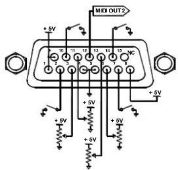
Gameport Connector
The gameport connector (15pin D-type) lets you add additional controllers such as an analogue joystick, or a third MIDI output socket using a standard gameport to MIDI adapter.
Note: this port has no MIDI input connection.
This interface will convert the movement of a connected joystick into MIDI CC and Note information; it cannot be used to control PC games, so don't try it with your latest flight sim.....
It is also possible to build a custom interface using general purpose switches and potentiometers. We recommend 10k or 20k ohm linear law pots. A simple schematic is shown here.

Footswitch Connector
This 1/4" TRS socket is used to connect a footswitch or expression pedal as an additional MIDI controller. Most standard foot pedals should be satisfactory, for example, the Roland EV-5.
MIXER SECTION — BPM COUNTER
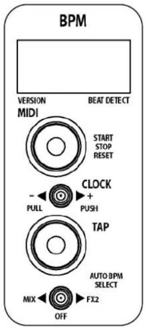


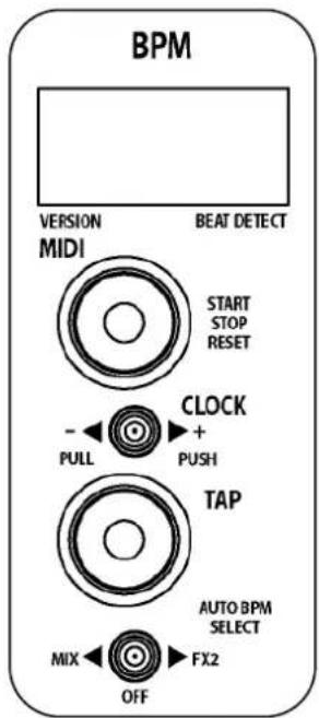
BPM Display Displays the te
Displays the tempo of an analysed piece of music, rounded up to the nearest whole number.
On power-up, and when the detector is reset, the display will show a line of three dashes.
When an audio source is routed to the auto beat detector, a dot in the bottom right hand corner will flash to indicate that BPM analysis is taking place.
The display can also show the BPM to the nearest decimal place by pressing and holding the TAP button. This will shift all digits one place to the left.
If the internal MIDI clock has been disabled 'OFF' will be continuously displayed.
2 MIDI Start / Stop Button Sends MIDI start/stop message Note that these messages are se
Sends MIDI start/stop messages to any connected sequencer. Note that these messages are sent on release of the switch.
Pressing and holding this switch will reset the auto BPM detector but won't change the current status of the Stop/Start control.
Pressing and holding this switch for approximately 5sec will turn off the Xone:4D's internal MIDI clock and the BPM display will change to OFF. Pressing and holding the STOP/START button again until the three dashes are displayed will reset the BPM and turn the MIDI clock back ON
The LED ring associated with this control will glow RED when a Start message is sent, and will also turn ON/OFF when a MIDI STOP/START/PAUSE command is received from an external MIDI device connected to the MIDI IN socket of the Xone:4D
3 MIDI Clock Push / Pull Switch
When attempting to get a sequencer, such as Ableton Live 5, to play in time with another music source, for example a CD or turntable which has been analysed by the auto beat detector, it is not always possible to get it to start exactly at the beginning of a bar. This control lets the DJ speed up or slow down the MIDI clock, rather like pushing or pulling a turntable platter when beat matching.
Pulling the lever to the left will slow the clock and the BPM reading will drop, pushing the lever to the right will speed up the clock and the BPM reading will rise.
When released, the MIDI clock will revert to the originally displayed BPM.
You can manually set the BPM to any speed between 70 and 400 by pulling or pushing the lever; when the desired speed is indicated on the display, press the TAP button to lock the MIDI clock to this speed. To fine tune the BPM to an exact figure, press and hold the TAP button and when the decimal is displayed, the speed can be altered by 0.1BPM again by using the Push/Pull lever.
MIXER SECTION — BPM COUNTER
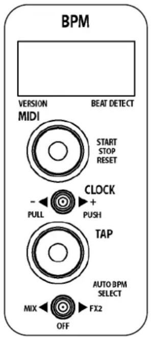
BPM Tap Tempo Button
This control is used to tap in a beat manually at any speed between 70 and 400 BPM. The taps are averaged, so the greater number of taps the more accurate the result.
The tap button can also be used as a guide for the auto beat detector on complex rhythms by helping the analyser lock onto the correct pattern, for instance drum 'n bass tracks can occasionally be displayed at half the actual BPM. By tapping in the approximate beat the analyser will re-sync to the correct tempo.
Pressing and holding the tap tempo button shifts the BPM display one place to the left so that the decimal can be shown.
When the BPM is being speeded up or down using the push/pull lever, pressing the tap button will store the currently displayed tempo.
The light ring associated with this control will flash in time with the current BPM speed, usually along with the kick drum, though occasionally the detector will synchronize to other rhythmic elements of a track such as a hi-hat line. This will not affect its accuracy. Tapping a few beats in manually will force the detector to re-sync to the beat.
5 Auto BPM Audio Source Switch
This selects the audio source for the auto beat detection circuit.
If MIX is selected, all music played through the main outputs of the Xone:4D will be analysed. This can be used to ensure that a mix compilation or DJ set is held at a strict tempo.
Select FX2 if you are using auto BPM detection to synchronize a remote sequencer to an audio source played through the Xone:4D, and are returning the audio output from the sequencer back into the mix. Ensure that all FX2 level pots are turned fully off except on the channel playing the track that you wish to synchronise to. If more than one channel at a time is routed to the FX2 mix buss it may confuse the BPM detector and result in an incorrect reading.
Switch to the OFF position if you want to enter the BPM manually and do not want any audio source to influence the tempo.
MIXER SECTION — LFO
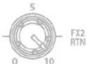
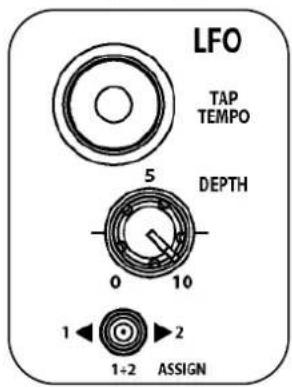


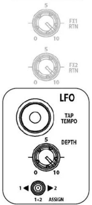
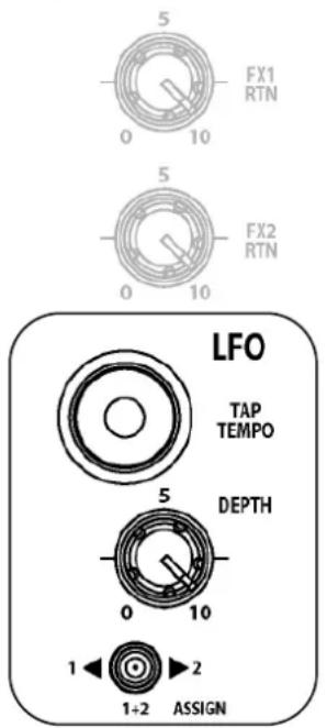
6 LFO Tap Tempo button Tapping this button will set
Tapping this button will set the speed of the LFO (low frequency oscillator) within the range of 0.25Hz - 3.33Hz (15 - 200 BPM)
The LFO speed can be displayed on the BPM meter by pressing and holding this button until dots appear after all of the digits—the BPM display now shows the tempo of the LFO. This will also let you set the LFO speed manually using the push/pull lever to raise or lower the speed from its current setting.
One very useful feature is the ability to copy the current BPM speed to the LFO. To do this, press and hold the LFO tap tempo button until the LFO speed is displayed on the BPM screen, then press the BPM tap button. The LFO speed will now be exactly the same as the BPM.
Note: The phase of the LFO will be set the moment the BPM tap button is pressed (whilst holding down the LFO tap button). This will let you synchronise the LFO to a particular sound on any track being fed to the auto beat detector. For example, pressing the BPM tap button on the beat will sync the LFO to the kick drum.
The light ring associated with this control will flash in time with the current LFO speed.
7 LFO Depth control This control sets the le
This control sets the level at which the filters will be modulated by the LFO. This works together with the filter frequency control. The maximum LFO filter modulation will occur if the LFO Depth control is fully clockwise with the filter frequency control fully anti-clockwise.
8 LFO Assign switch Selects which filter wi
Selects which filter will be modulated by the LFO. In its left position Filter 1 only is modulated, in the right hand position Filter 2 only is modulated. In the centre position both Filter 1 and Filter 2 will be modulated by equal amounts.
MIXER SECTION — THE LFO EDITOR
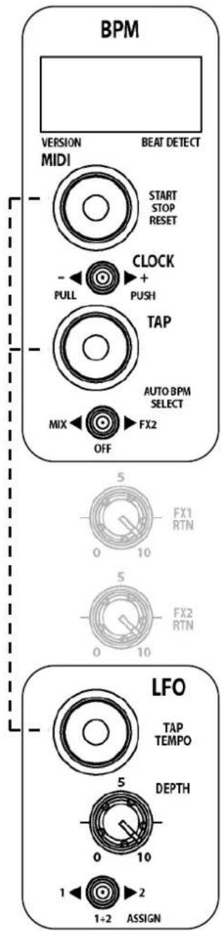
The LFO Editor allows real-time manipulation of the LFO waveform using the linear faders on the left and right MIDI pods of the Xone:4D. The LFO tempo can be set using the LFO Tap Tempo button or by synchronising the LFO tempo to the displayed BPM (see page 36).
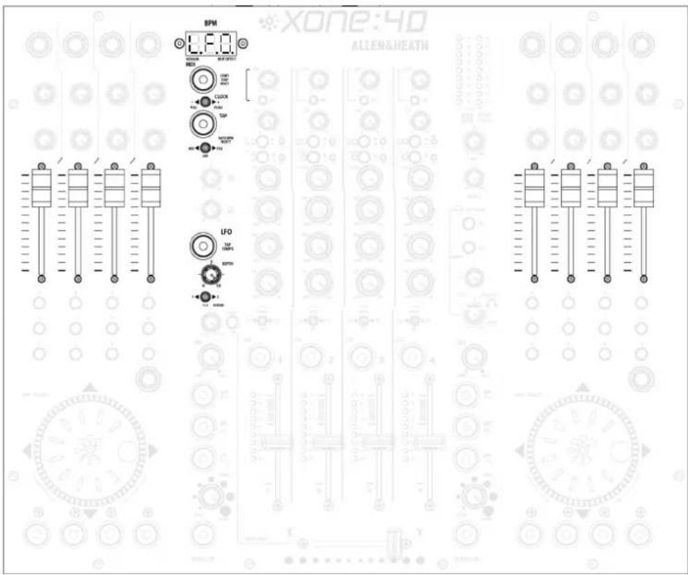
Enter LFO Edit Mode
To enter LFO Edit Mode, hold down the LFO Tap Tempo button until the LFO speed is displayed on the BPM screen and then press the MIDI Start/Stop button. The BPM screen will now display "L.F.O." to indicate that the surface is in LFO Edit Mode and the eight MIDI faders can be used to 'draw' the LFO waveform. All other MIDI controls will send their respective MIDI messages while the surface is in LFO Edit Mode.
Exit LFO Edit Mode
To exit LFO Edit Mode, press the MIDI start/stop button and the BPM display will show the current tapped or analysed BPM.
Resetting the LFO Waveform
To reset the LFO to its default (triangular) waveform, hold down the LFO Tap Tempo button until the LFO speed is displayed in the BPM window, then hold down the Start/Stop button until R.S.T. appears in the BPM window.
MIDI CONTROL SECTION
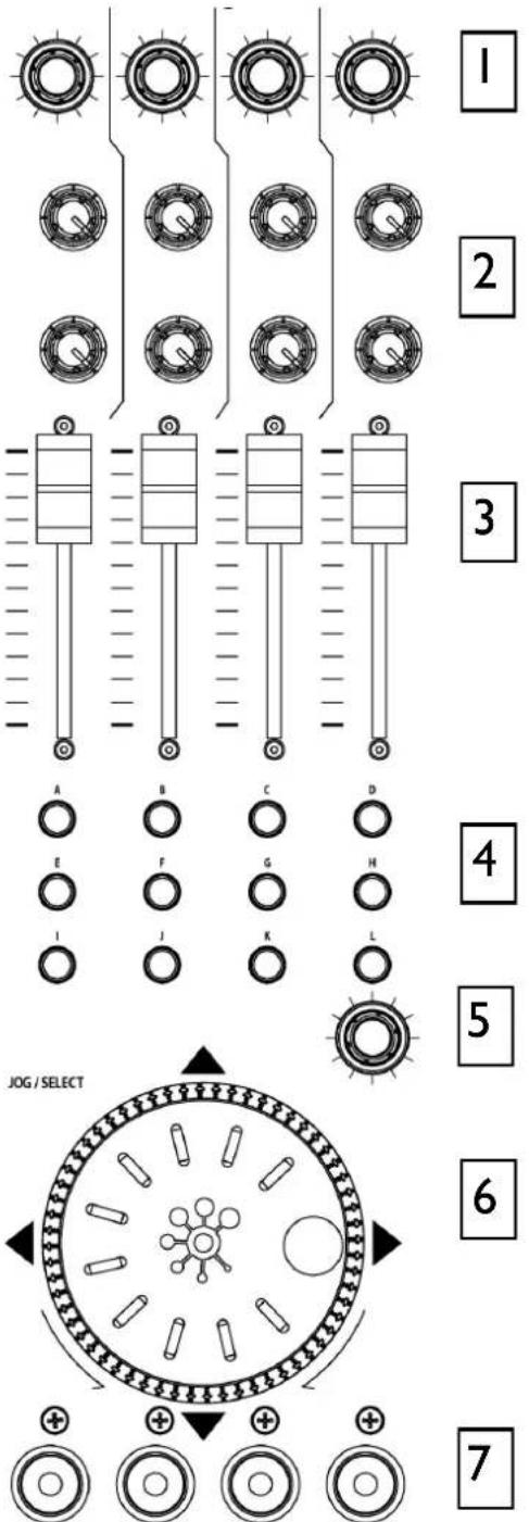

Rotary Encoders
Turning an encoder produces MIDI CC (continuous controller) messages with a unique controller number in two's complement binary encoding. Refer to the MIDI mapping diagram for the differences between Map 1 and 2 for these controls.
These encoders feature a built in momentary push switch. Pressing down on the encoder knob activates the switch and sends a "note on" MIDI message, releasing the switch sends a corresponding "note off" message.

Rotary Potentiometers
These controls are standard potentiometers with end stops and a centre detent for easy setting. Turning a pot from left to right will send MIDI messages with a unique CC number and a control value from 0 (fully left) to 127 (fully right).

Linear Faders
Moving a linear fader will send a MIDI message with a unique CC number and a control value from 0 (bottom) to 127 (top).

Push Buttons
There are 24 momentary action switches coded with letters A through to X for easy identification. Pressing a switch will send a unique "note on" MIDI message. Releasing the switch sends a corresponding "note off" message.

Rotary Encoder
A rotary encoder with switch, as above.

Jog Wheel
The jog wheel features an optical encoder, which produces CC messages in a similar way to the other encoders. Switches are located at the top, bottom, left and right of the wheel. Pushing down on the face of the wheel sends note on / note off messages.

Illuminated Push Buttons
Momentary action switches with red light ring indicators. Pressing a switch will send a "note on" MIDI message and turn on the indicator. Pressing the switch again will send another "note on" message and switch off the indicator.
MIDI CONTROL SECTION
MIDI Messages
The diagram below shows which controls are associated with MIDI CC (continuous controller) and note on/off messages. These controls send the MIDI messages shown when operated. The switch light ring indicators (except for start/stop and tap tempo) may be turned on or off by incoming MIDI messages.
MIDI Channel Number and Map
To change the MIDI map and channel number, please refer to the MIDI CHANNEL, MAP AND LIGHT PIPE SETUP sections on pages 11 and 12.
MIDI Shift Mode
All of the controls on the Xone:4D (with the exception of the crossfader, can be mapped a second time using the MIDI shift mode. To enter MIDI SHIFT MODE, hold down the encoder above the jog wheel on the left MIDI pod for approximately half a second. The BPM display will show SFT when the console is in shift mode. A fader pick up algorithm has been written into the software to ensure seamless integration between the two MIDI layers. In shift mode, the channel MIDI messages are sent on the default MIDI channel minus 1—i.e. if you are transmitting on MIDI channel 16 then shift mode will transmit on channel 15. The only exception is if the default channel is channel 1 then the shift mode will transmit on channel 2.
Allen & Heath 39 XONE:4D User Guide
MIDI IMPLEMENTATION CHART
| Function | Transmitted | Received | Remarks |
| Basis ChannelDefaultOption | 161-16 | 161-16 | Selectable withConfiguration Utility |
| ModeDefaultMessagesAltered | XXX | XXX | |
| Note Number O O Refer to Diagram. MID | note messages received as well as transmitted for all push buttons with light rings, except MIDI Start/Stop and BPM/LFO Tap Tempo buttons. | ||
| VelocityNote ONNote OFF | XXX | XXX | |
| After touchKeysChannel | XXX | XXX | |
| Pitch Bend X X | |||
| Control Change1345678-45 | OOOOOO | XXXXXXXX | Joystick YJoystick XFootswitchCrossfaderFilter 1 FreqFilter 2 FreqDedicated Controls |
| Program Change X X | |||
| System Exclusive X X | |||
| System CommonSong PositionSong SelectTune Request | XXX | XXX | |
| System Real TimeClockCommands | OOO | XXX | |
| Aux MessagesLocal On/OffAll Notes OffActive SensingSystem Reset | XXX | XXX | |
MIDI NOTE CHART
| Note No.(Hex) | Note No.(Decimal) | Note Name |
| 000C-2 | 3654F#2 | |
| 011C#-2 | 3755G2 | |
| 022D-2 | 3856G#2 | |
| 033D#-2 | 3957A2 | |
| 044E-2 | 3A58A#2 | |
| 055F-2 | 3B59B2 | |
| 066F#-2 | 3C60C3 | |
| 077G-2 | 3D61C#3 | |
| 088G#-2 | 3E62D3 | |
| 09 | 9 | A-2 |
| 0A10 | A#-2 | 4064E3 |
| 0B11 | B-2 | 4165F3 |
| 0C12 | C-1 | 4266F#3 |
| 0D13 | C#-1 | 4367G3 |
| 0E14D-1 | 4468G#3 | |
| 0F15 | D#-1 | 4569A3 |
| 1016 | E-1 | 4670A#3 |
| 11 | 17 | F-1 |
| 12 | 18 | F#-1 |
| 1319 | G-1 | 4973C#4 |
| 1420 | G#-1 | 4A74D4 |
| 1521A1 | 4B75D#4 | |
| 1622A#1 | 4C76E4 | |
| 1723B1 | 4D77F4 | |
| 1824C0 | 4E78F#4 | |
| 19 | 25 | C#0 |
| 1A | 26 | D0 |
| 1B27D#0 | 5181A4 | |
| 1C28E0 | 5282A#4 | |
| 1D29F0 | 5383B4 | |
| 1E30 | F#0 | 5484C5 |
| 1F31G0 | 5585C#5 | |
| 2032G#0 | 5686D5 | |
| 2133A0 | 5787D#5 | |
| 2234A#0 | 5888E5 | |
| 2335B0 | 5989F5 | |
| 2436C1 | 5A90F#5 | |
| 25 | 37 | C#1 |
| 2638D1 | 5C92G#5 | |
| 2739D#1 | 5D93A5 | |
| 28 | 40 | E1 |
| 29 | 41 | F1 |
| 2A42F#1 | 6096 | C6 |
| 2B | 43 | G1 |
| 2C44G#1 | 6298D6 | |
| 2D | 45 | A1 |
| 2E | 46 | A#1 |
| 2F | 47 | B1 |
| 30 | 48 | C2 |
| 31 | 49 | C#2 |
| 32 | 50 | D2 |
| 33 | 51 | D#2 |
| 34 | 52 | E2 |
| 35 | 53 | F2 |
| Note No. (Hex) | Note No. (Decimal) | Note Name |
| 3F | 63 | D#3 |
| 47 | 71 | B3 |
| 48 | 72 | C4 |
| 4F | 79 | G4 |
| 50 | 80 | G#4 |
| 5B | 91 | G5 |
| 5E | 94 | A#5 |
| 5F | 95 | B5 |
| 61 | 97 | C#6 |
| 63 | 99 | D#6 |
| 64 | 100 | E6 |
| 65 | 101 | F6 |
| 66 | 102 | F#6 |
| 67 | 103 | G6 |
| 68 | 104 | G#6 |
| 69 | 105 | A6 |
| 6A | 106 | A#6 |
| 6B | 107 | B6 |
The VCF Filters
A voltage controlled filter is an audio filter where the cut-off frequency is altered by a DC control voltage rather than a variable resistor. This produces a much wider operating range and more control over the filter response to create unlimited combinations of tonal effect.
Two stereo VCFs are provided, one either side of the crossfader. Each can be switched in or out and has its own frequency sweep control. A Low Frequency Oscillator (LFO) provides filter modulation.
LFO modulation
The LFO automatically sweeps the cut-off frequency up and down according to the beat entered by tapping the tap tempo button or locking to the analysed BPM. The LFO can be applied to Filter 1, Filter 2, or both filters together for additional cyclic filter modulation effects.
Filter Type Select
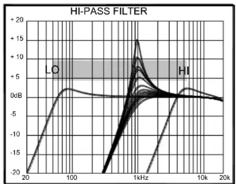
The filters are ‘state variable’. This means that they provide three simultaneous filter types, high-pass, band-pass and low-pass. Three large illuminated switches select which type is active. You can press any combination together to create different response types such as ‘notch’ and an interesting ‘all-pass’ effect. The switches are ‘soft switched’ for live performance, meaning that the audio signal is ramped between filter states to prevent audible clicks.
Note that the last selected type is lost when power is removed from the console. The LPF is always selected when power is applied.
The graphs below show the effect on the audio frequency response for the three filter types. The range of sweep from low to high frequency is shown together with the effect of adjusting RESONANCE (one frequency with several resonance settings shown).
The vertical scale shows the amount of cut or boost around the normal 0dB operating level. The horizontal scale shows the change in frequency from low (bass) to high (treble).
line
| Frequency | LO | HI | | --------- | ----- | ------ | | 20 | -20 | -20 | | 100 | 0 | 0 | | 1kHz | +15 | +15 | | 10k | 0 | 0 | | 20k | 0 | 0 |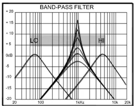
line
| Frequency | LC | HI | | --------- | ----- | ------ | | 20 | -10 | -10 | | 100 | -20 | -5 | | 1kHz | +15 | +5 | | 10k | -20 | -10 | | 20k | -10 | -15 |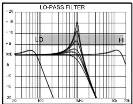
line
| Frequency | LO (dB) | HI (dB) | | --------- | ------- | ------- | | 20 | ~0 | ~0 | | 100 | ~0 | ~0 | | 1kHz | ~+15 | ~-5 | | 10k | ~0 | ~0 | | 20k | ~-5 | ~-10 |OPERATING LEVELS
It is most important that the system level settings are correctly set. It is well known that many DJs push the level to maximum with meters peaking hard in the belief that they are getting the best from the system. THIS IS NOT THE CASE! The best can only be achieved if the system levels are set within the normal operating range and not allowed to peak. Peaking simply results in signal distortion, not more volume. It is the specification of the amplifier / speaker system that sets the maximum volume that can be achieved, not the console. The human ear too can fool the operator into believing that more volume is needed. Be careful as this is in fact a warning that hearing damage will result if high listening levels are maintained. Remember that it is the QUALITY of the sound that pleases the ear, not the VOLUME.
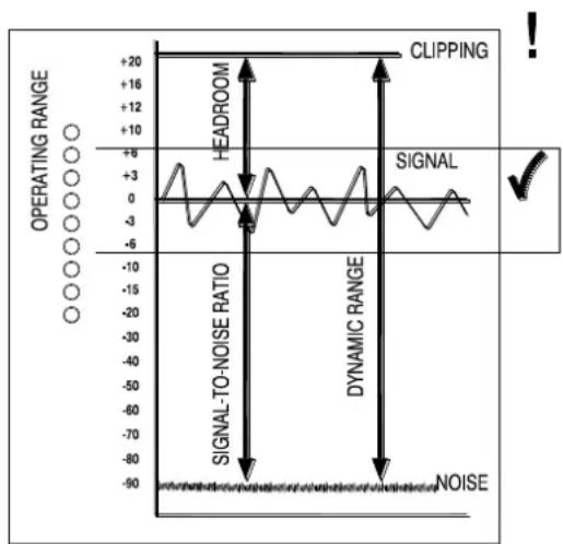
This diagram illustrates the operating range of the audio signal.
NORMAL OPERATING RANGE. For normal music the signal should range between -6 and +6 on the meters with average around 0dB. This allows enough HEADROOM for unexpected peaks before the signal hits its maximum CLIPPING voltage and distorts.
It also achieves the best SIGNAL-TO-NOISE-RATIO by keeping the signal well above the residual NOISE FLOOR (system hiss).
The DYNAMIC RANGE is the maximum signal swing available between the residual noise floor and clipping.
An important note ...
The human ear is a remarkable organ with the ability to compress or 'shut down' when sound levels become too high. Do not interpret this natural response as a reason to turn the system volume up further! As the session wears on ear fatigue may set in, and the speaker cones may become hot so reducing the effectiveness of the system and listeners to gain any benefit from increased volume.
The connection to earth (ground) in an audio system is important for two reasons:
SAFETY - To protect the operator from high voltage electric shock, and
AUDIO PERFORMANCE - To minimise the effect of earth (ground) loops which result in audible hum and buzz, and to shield the audio signals from interference.
For safety it is important that all equipment earths are connected to mains earth so that exposed metal parts are prevented from carrying high voltage which can injure or even kill the operator. It is recommended that a qualified system engineer check the continuity of the safety earth from all points in the system including microphone bodies, turntable chassis, equipment cases, and so on.
The same earth is also used to shield audio cables from external interference such as the hum fields associated with power transformers, lighting dimmer buzz, and computer radiation. Problems arise when the signal sees more than one path to mains earth. An ‘earth loop’ (ground loop) results causing current to flow between the different earth paths. This condition is usually detected as a mains frequency audible hum or buzz.
To ensure safe and trouble-free operation we recommend the following:
Have your mains system checked by a qualified electrician. If the supply earthing is solid to start with you are less likely to experience problems.
Do not remove the earth connection from the console mains plug. The console chassis is connected to mains earth through the power cable to ensure your safety. Audio 0V is connected to the console chassis internally. If problems are encountered with earth loops operate the audio 'ground lift' switches on connected equipment accordingly, or disconnect the cable screens at one end, usually at the destination.
Make sure that turntables are correctly earthed. A chassis earth terminal is provided on the console rear panel to connect to turntable earth straps.
Use low impedance sources such as microphones and line level equipment rated at 200 ohms or less to reduce susceptibility to interference. The console outputs are designed to operate at very low impedance to minimise interference problems.
Use balanced connections for microphones and mix output as these provide further immunity by cancelling out interference that may be picked up on long cable runs. To connect an unbalanced source to a balanced console input, link the cold input (XLR pin 3 or jack ring) to 0V earth (XLR pin 1 or jack sleeve) at the console. To connect a balanced XLR output to unbalanced equipment, link the cold output to 0V earth at the console.
Use good quality cables and connectors and check for correct wiring and reliable solder joints. Allow sufficient cable loop to prevent damage through stretching.
If you are not sure ... Contact your service agent or local Allen & Heath dealer for advice.
CABLES AND CONNECTIONS
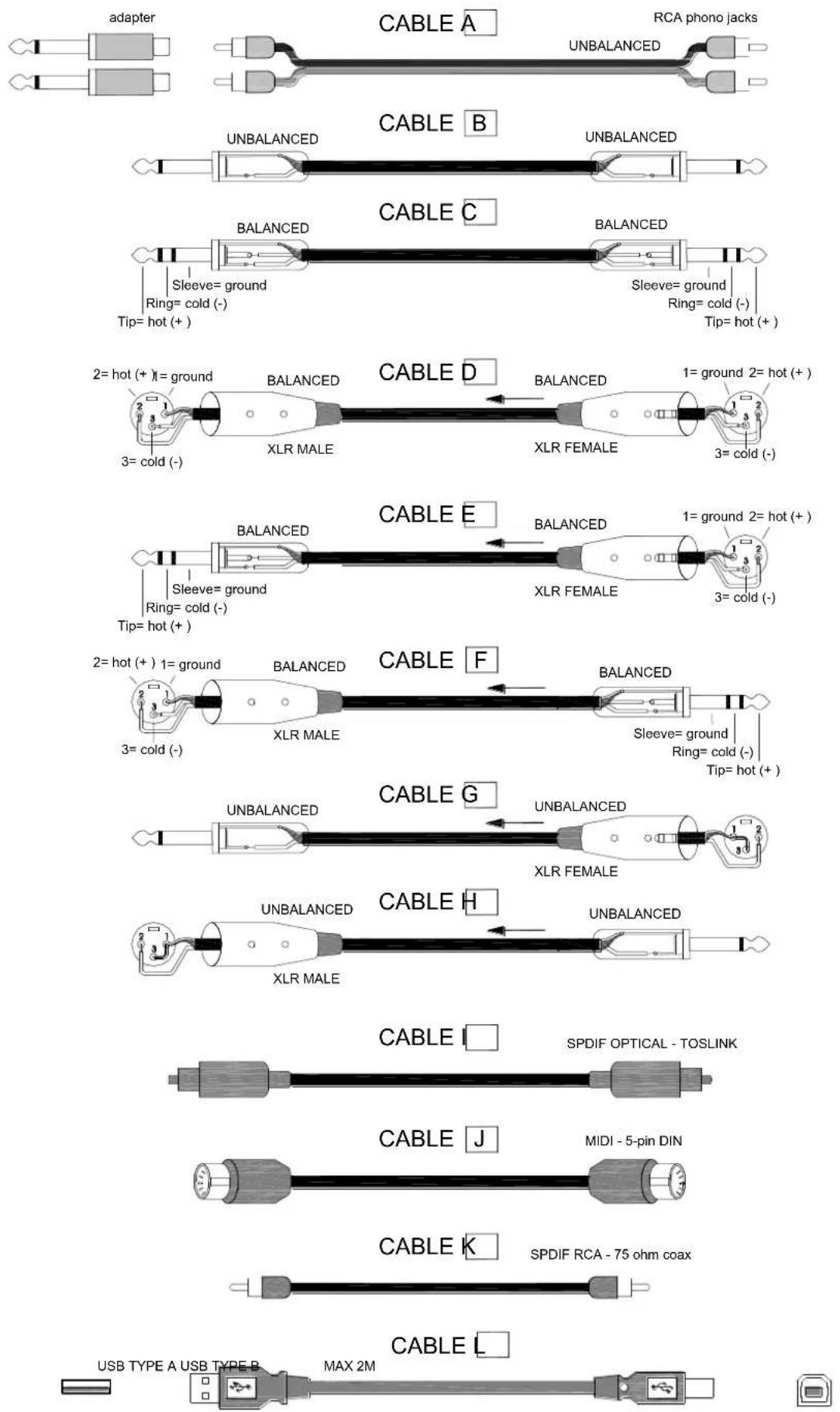
Internal Link Options
The Xone:4D offers several internal option settings:
- FX1 and FX2 Return Routing—The FX1 and FX2 Returns are set, by default, to route to the main LR Mix. Link options allow the return to be routed through either Filter 1 or Filter 2.
- Disabling / Enabling RIAA Preamps—All channels are fitted with RIAA preamplifiers. Link options allow the RIAA preamplifier stage to be enabled or disabled. When disabled, the Phono input becomes a Line input.
- FX2 Pre / Post Fade Assignment—The FX2 channel send is set, by default, to pre-fader. Link options allow the channel FX2 send to become post-fader.
CAUTION : Refer the above link options to an Allen and Heath approved service centre only. To reduce the risk of electric shock do not perform any servicing other than that described in the operating instructions unless you are qualified to do so.
Replacing the Crossfader
Replacement crossfader Assembly: Allen & Heath Part No. 003-579. Please contact your Allen and Heath approved service centre to undertake crossfader replacement.
SPECIFICATIONS
Operating levels
| Main outputs | +4dBu XLR |
| Monitor | 0dBu RCA |
| FX sends | -2dBu RCA |
| Maximum output level | +26dBu |
| Mic Sensitivity | -45 to -15dBu |
| RIAA input sensitivity | 7-100mV 47K/330pF |
| Frequency response Line in to Mix out | 20 Hz to 30KHz +0/-2dB |
| Distortion at 1kHz Line in at +0Vu out | <0.02% |
| Main Mix noise 22Hz— 22KHz unweighted | <-80dBu (84dB S/N) |
| Residual Mix noise22Hz— 22KHz unweighted | <-97dBu |
| Equalization | 3-band +6dB/off (kill), 120Hz, 1.2kHz, 10kHz |
| Fader Shutoff | <-90dB |
Dimensions and Weights
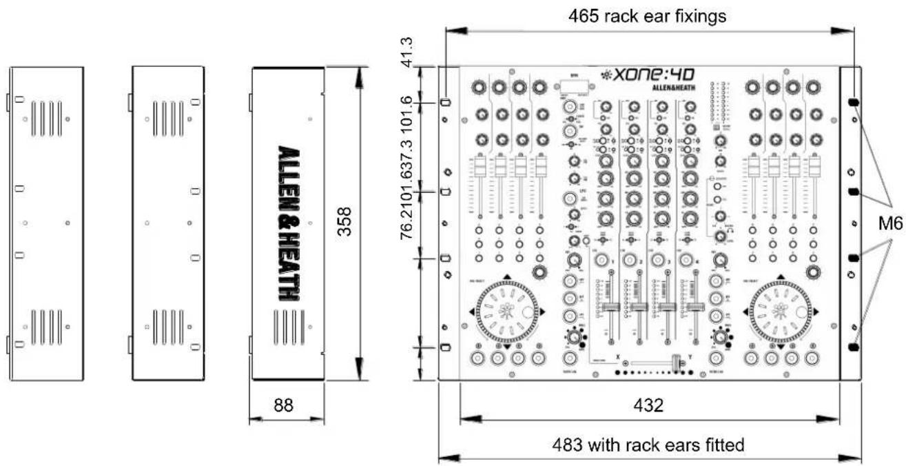
The console is fitted with rubber feet for desktop operation. A screw on rack ear kit is included for 19" rack or plinth mounting.
Width Height Depth Weight
Desktop 432 mm (17") 88 mm (3.5") 358 mm (14") 5kg (11 lbs)
Rack ears fitted 483 mm (19") 88 mm (3.5") 358 mm (14")
Packed 575 mm (22.6") 195 mm (7.7") 490 mm (15.7") 6 kg (13.2 lbs)
Rack ears allow permanent fixing in a plinth or rack system. They can be fitted two ways; either with the flange flush with the top panel or flush with the underside of the chassis. The rack ears are fixed in place using the 6x M4 screws provided. Ensure that air vents are not obstructed.
PRODUCT REGISTRATION
Registering your product
Please go to www.allen-heath.com/register.asp and register your product's serial number and your details. By registering with us and becoming an official Registered User, you will ensure that any warranty claim you might make is actioned quickly and with the minimum delay.
Alternatively, you may either copy or cut off this section of the page, fill in the details, and return it by mail to:
Allen & Heath Ltd, Kernick Industrial Estate, Penryn, Cornwall TR10 9LU, UK
ALLEN&HEATH PRODUCT REGISTRATION
Thankyou for buying an Allen & Heath product. We hope that you're happy with it and that you enjoy many years of faithful service with it.
SERIAL NUMBER
Please return this section of the card by mail and retain the other part for your records. You can also register online at www.allen-heath.com. Thanks for your help.
Your Name:
Company Name:
Address 1:
Address 2:
Town/City:
County/State:
Country:
Postcode/Zip:
Telephone:
Email:
Why did you choose this console?
Which other products did you you consider before choosing A&H?
Is there any thing you would like to improve on this mixer?
What audio magazines do you read?
If you were going to design a mixer for your work, what are the 6 most important features it should have (in order of importance)
1
2
3
4
5
6
We may use the information you provide to inform you of future product developments. We will not give or sell this data to third parties. Please indicate with an 'x' if you do not wish to receive any further communications from us.

- XONE:4D
- Limited One Year Warranty
- Conditions Of Warranty
- CONTENTS
- PACKED ITEMS
- SOFTWARE INSTALLATION PC
- STOP!
- Software Installation (Windows 2000, XP and Vista)
- Do not connect the 4D to the PC at this time.
- 4— Select Install the driver
- CHECKING THE DRIVER INSTALLATION—WINDOWS
- Checking the Driver Installation
- SOFTWARE INSTALLATION—APPLE MAC
- Mac OSX
- CHECKING THE DRIVER INSTALLATION—APPLE MAC
- MIDI CHANNEL SETUP
- MIDI Channel Number
- Hot Setup
- Changing the MIDI Map
- Map I (Traktor default)
- Map 2 (Ableton default)
- SOUNDCARD ARCHITECTURE
- ANALOGUE INPUTS:
- DIGITAL INPUTS:
- ANALOGUE OUTPUTS:
- DIGITAL OUTPUTS:
- SPDIF DIGITAL INPUTS AND OUTPUTS
- SOFTWARE DESCRIPTION
- Soundcard Input Ableton Descriptor Traktor Descriptor
- Soundcard Output Ableton Descriptor Traktor Descriptor
- Supported Buffer Sizes
- ABLETON SET UP
- TRAKTOR SET UP
- PANEL DRAWINGS
- INTRODUCTION TO THE XONE:4D
- MIXER
- FILTERS
- FX LOOPS
- OUTPUTS
- BPM COUNTER
- UV REACTIVE PAINT
- MIDI CONTROL
- SOUNDCARD
- SOUNDCARD INPUT BLOCK DIAGRAM
- Note:
- SOUNDCARD OUTPUT / MIDI BLOCK DIAGRAM
- MIXER SECTION — CHANNEL INPUT
- |
- FX I-2 send controls
- 2
- Input Selection
- Soundcard Input Selection Switches
- Channel Level Control
- Channel Equalizer/Isolator
- Filter/Crossfade Assignment
- Cue Switch
- Channel Meter
- Channel Fader
- MIXER SECTION — MIX AND MONITOR
- Mix / Monitor Meters
- Record to FX2 Switch
- Mix Master Level Control
- Monitor Master Level Control
- Cue Active LED
- Monitor Select Switches
- Headphones Level Control
- MIXER SECTION — FILTERS and LFO
- LFO Tap Tempo button
- LFO Depth control
- LFO Filter Assign Switch
- Resonance Control
- HPF Button
- BPF Button
- LPF Button
- Frequency Sweep Control
- Filter On Switch
- Crossfader
- Xfade on switch
- XFade Curve Control
- FRONT CONTROLS & CONNECTORS
- Headphones Outputs
- Mic EQ Controls
- Mic Input
- Mic Level Control
- REAR CONNECTORS
- AC Mains Input
- Important: Read the SAFETY INSTRUCTIONS sheet included with the Xone:4D and printed on the rear panel.
- FXI-2 Line Return Input
- CHI-4 Stereo Line Input
- CHI-3 Stereo Phono Input
- Chassis Earth Terminal
- Mix Output
- Monitor Output
- FXI-2 Send Output
- Soundcard Outputs
- MIDI Input / Output
- USB Connector
- Gameport Connector
- Footswitch Connector
- MIXER SECTION — BPM COUNTER
- BPM Display Displays the te
- MIDI Start / Stop Button Sends MIDI start/stop message Note that these messages are se
- MIDI Clock Push / Pull Switch
- BPM Tap Tempo Button
- Auto BPM Audio Source Switch
- MIXER SECTION — LFO
- LFO Tap Tempo button Tapping this button will set
- LFO Depth control This control sets the le
- LFO Assign switch Selects which filter wi
- MIXER SECTION — THE LFO EDITOR
- Enter LFO Edit Mode
- Exit LFO Edit Mode
- Resetting the LFO Waveform
- MIDI CONTROL SECTION
- Rotary Encoders
- Rotary Potentiometers
- Linear Faders
- Push Buttons
- Rotary Encoder
- Jog Wheel
- Illuminated Push Buttons
- MIDI Messages
- MIDI Channel Number and Map
- MIDI Shift Mode
- The VCF Filters
- LFO modulation
- Filter Type Select
- OPERATING LEVELS
- An important note ...
- Internal Link Options
- Replacing the Crossfader
- SPECIFICATIONS
- Dimensions and Weights
- PRODUCT REGISTRATION
- Registering your product
- ALLEN&HEATH PRODUCT REGISTRATION
Brand : ALLEN & HEATH
Model : XONE:4D
Category : DJ Equipment