TS108 - Subwoofer EVE Audio - Free user manual and instructions
Find the device manual for free TS108 EVE Audio in PDF.

| Product Type | Subwoofer |
| Model | TS108 |
| Dimensions (W x H x D) | 280 x 415 x 365 mm (11.02 x 16.34 x 14.37 in) |
| Weight | 11.5 kg (25.3 lb) |
| Woofer Size | 195 mm / 8" |
| Frequency Range (-3dB) | 29 - 300 Hz (LFE mode) |
| Maximum SPL @ 1m | 105 dB |
| Amplifier Power (short term) | 150 W |
| Amplifier Type | PWM |
| Input Sensitivity | +8 dBu / +22 dBu (switchable) |
| Connections | Balanced XLR In/Out (L+R), Unbalanced RCA In, LFE In/Out |
| System Volume (Sub + Sat) | -∞ to +6 dB |
| Subwoofer Volume | -∞ to +6 dB |
| Satellite Filter (High-Pass) | Flat / 80 Hz (switchable) |
| Subwoofer Filter (Low-Pass) | 60-140 Hz + LFE mode (variable) |
| Phase Switch | 0° / 180° |
| Remote Control | IR (included) |
| Auto-Standby | Yes (switchable via DIP switch) |
| Power Consumption (Standby) | < 1 W |
| Power Consumption (Max) | 170 VA |
| Power Connector | IEC with integrated fuse |
| User-Replaceable Fuse | Yes (refer to fuse values on product) |
| Cleaning | Use a dry cloth only |
| Servicing | Refer all servicing to qualified personnel |
Frequently Asked Questions - TS108 EVE Audio
User questions about TS108 EVE Audio
0 question about this device. Answer the ones you know or ask your own.
Ask a new question about this device
Download the instructions for your Subwoofer in PDF format for free! Find your manual TS108 - EVE Audio and take your electronic device back in hand. On this page are published all the documents necessary for the use of your device. TS108 by EVE Audio.
USER MANUAL TS108 EVE Audio
natural_image
Abstract geometric logo design with symmetrical black lines forming a V-shape (no text or symbols)eve audio
TS107 TS108
SAFETY INSTRUCTIONS
- READ these instructions.
- KEEP these instructions.
- HEED all warnings.
- FOLLOW all instructions.
- DO NOT use this apparatus near water.
- CLEAN ONLY with dry cloth.
- DO NOT block any ventilation openings. Install in accordance with the manufacturer's instructions.
- DO NOT install near any heat sources such as radiators, heat registers, stoves, or other apparatus (including amplifiers) that produce heat.
- DO NOT defeat the safety purpose of the polarized or grounding-type plug. A polarized plug has two blades with one wider than the other. A grounding type plug has two blades and a third grounding prong. The wider blade or the third prong are provided for your safety. If the provided plug does not fit into your outlet, consult an electrician for replacement of the obsolete outlet.
- PROTECT the power cord from being walked on or pinched particularly at plugs, convenience receptacles, and the point where they exit from the apparatus.
- ONLY USE attachments/accessories specified by the manufacturer.
- USE ONLY with the cart, stand, tripod, bracket, or table specified by the manufacturer, or sold with the apparatus. When a cart is used, use caution when moving the cart/apparatus combination to avoid injury from tip-over.
- UNPLUG this apparatus during lightning storms or when unused for long periods of time.
- REFER all servicing to qualified service personnel. Servicing is required when the apparatus has been damaged in any way, such as power-supply cord or plug is damaged, liquid has been spilled or objects have fallen into the apparatus, the apparatus has been exposed to rain or moisture, does not operate normally, or has been dropped.
EVE Audio product manual
- To reduce the risk of fire or electric shock, do not expose this apparatus to rain or moisture. The apparatus shall not be exposed to dripping or splashing and that objects filled with liquids, such as vases, shall not be placed on apparatus.
- Where the MAINS plug or an appliance coupler is used as the disconnect device, the disconnect device shall remain readily operable.
- DO NOT overload wall outlets or extension cords beyond their rated capacity as this can cause electric shock or fire.
- No naked flame sources, such as lighted candles, should be placed on the apparatus.
- Minimum distances around the apparatus for sufficient ventilation.
- The ventilation should not be impeded by covering the ventilation openings with items, such as newspapers, table cloths, curtains, etc.
- Correct Disposal of this product. This marking indicates that this
product should not be disposed with other household wastes throughout the EU. To prevent possible harm to the environment or human health from uncontrolled waste disposal, recycle it responsibly to promote the sustainable reuse of material resources. To return your used device, please use the return and collection systems or contact the retailer where the product was purchased. They can take this product for environmental safe recycling.
- The lightning flash with arrowhead symbol within an equilateral
triangle is intended to alert the user to the presence of uninsulated "dangerous voltage" within the product's enclosure that may be of sufficient magnitude to constitute a risk of electrical shock to persons.
- The exclamation point, within an equilateral triangle, is intended to alert the user to the presence of important operating and maintenance (servicing) instructions in the literature accompanying the product.
24. CAUTION RISK OF ELECTRIC SHOCK. DO NOT OPEN. AVIS : RISQUE DE CHOC ÉLECTRIQUE – NE PAS OUVRIR. WARNING: Do Not Open! Risk of Electrical Shock. Voltages in this equipment are hazardous to life. No user-serviceable parts
inside. Refer all servicing to qualified service personnel. Place the equipment near a main power supply outlet and make sure that you can easily access the power breaker switch.
- WARNING: This product is intended to be operated ONLY from the AC Voltages listed on the back panel or included power supply of the product. Operation from other voltages other than those indicated may cause irreversible damage to the product and void the products warranty. The use of AC Plug Adapters is cautioned because it can allow the product to be plugged into voltages in which the product was not designed to operate. If the product is equipped with a detachable power cord, use only the type provided with your product or by your local distributor and/or retailer. If you are unsure of the correct operational voltage, please contact your local distributor and/or retailer.
EVE Audio product manual
TABLE OF CONTENT
1. INTRODUCTION 6
2. QUICK START....7
2.1. First Steps....7
2.2. Subwoofer Connection....7
2.3. Powering On 7
3. OPERATION 8
3.1. First Steps....8
3.2. Operating Modes....9
3.3. Powering on/off: Standby Mode 9
3.4. Volume Mode....9
3.5. Settings Menu 11
3.6. Filter 11
3.7. Sat. Filter (only when using the XLR ins & outs).... 12
3.8. Sub Filter 12
3.9. Sub Phase....12
3.10. LED Mode.... 12
3.11. Saving Your Settings 13
3.12. Remote Control.... 13
3.13. Power Switch 15
3.14. DIP Switches.... 15
3.15. Power Connector (IEC) 16
4. POSITIONING ....16
4.1. Subwoofer Positioning.... 16
4.2. Height and Distance 16
4.3. Stereo Setup + Subwoofer (2.1).... 17
4.4. Multichannel Setup (5.1) 18
4.5. Room Acoustics 19
5. TECHNICAL SPECIFICATIONS....21
6. COMPLIANCE....22
7. WARRANTY....23
1. INTRODUCTION
Thank you for your time and interest in the EVE Audio product range.
EVE Audio is a loudspeaker manufacturer based in Berlin, Germany, that specializes in the development and design of unique studio monitors.
The use of first-class components is our highest priority because we firmly believe this is the only way to manufacture first-class products.
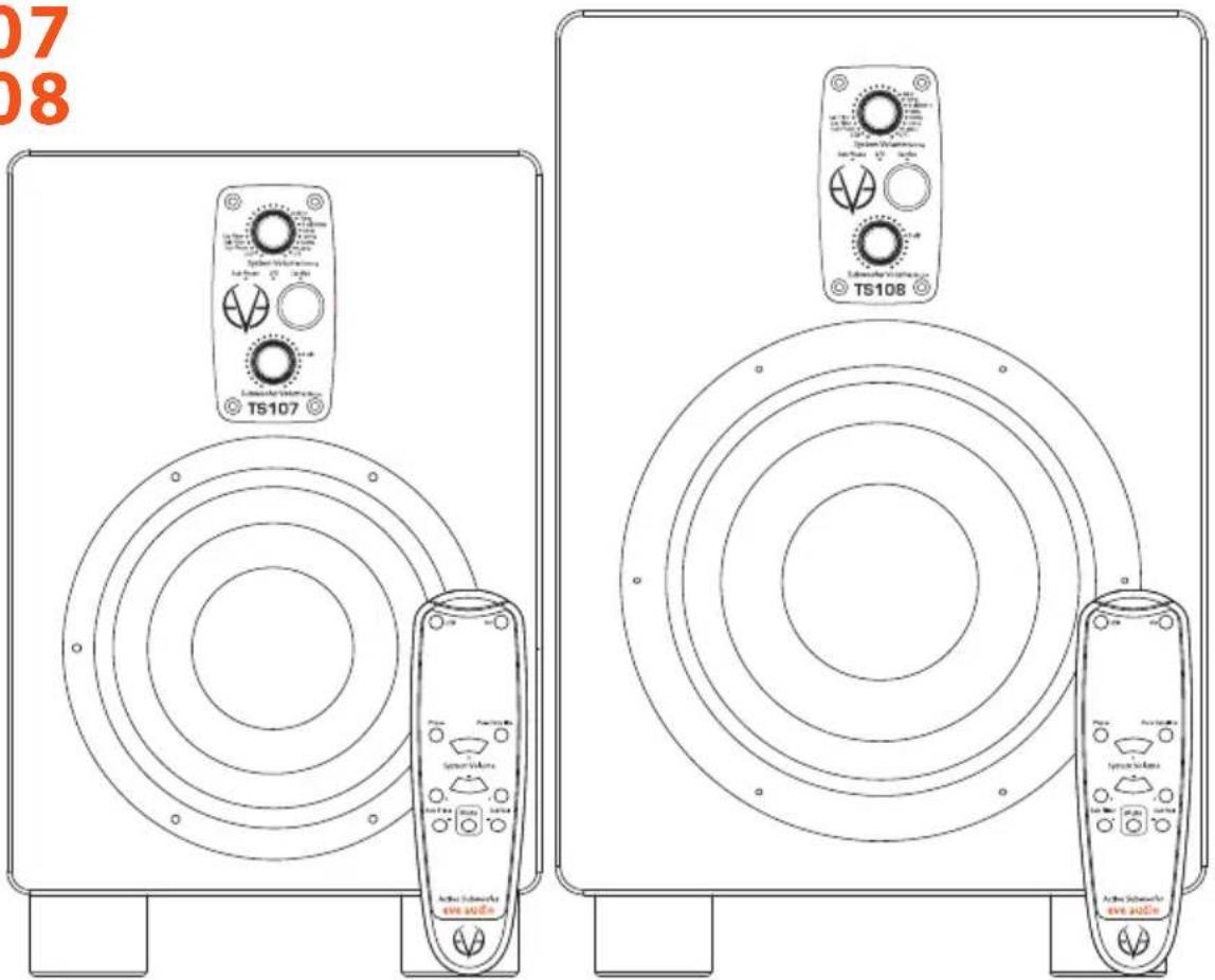
You have chosen a TS107 or TS108 subwoofer from our ThunderStorm series. Both models make use of passive radiators instead of a bass reflex port. This allows for a lower tuning of the subwoofer and avoids the emergence of hum, which is unavoidable when applying the bass reflex port design. The passive radiator is on the bottom side of the subwoofer.
All subwoofers of the ThunderStorm series are the ideal extension for the two, three and four-way systems of the EVE Audio SilverCone series. They can be easily integrated in any situation thanks to their ThunderStorm Chassis (6,5" or 8"), PWM amplifiers (100 and 150 Watt), accurate DSP technology and IR remote control. Moreover, both TS107 and TS108 offer additional features in order to extend the frequency response of our SC203 Master/Slave system optimally.
We wish you a lot of fun with your EVE Audio subwoofer. If you have any questions regarding our products, do not hesitate to contact your nearest dealer or get directly in touch with us... We will be more than happy to help you out!
All the best from Berlin.
The EVE Audio Team
EVE Audio product manual
2. QUICK START
If you already have experience with studio subwoofers, the Quick Start guide ought to be more than enough to get you started.
For unexperienced users we recommend reading the whole user's manual in order to prevent any misuse.
2.1. First Steps
Check the package components (loudspeaker, remote control + batteries, user's manual, power cord).
Check the setting of the DIP Switches (Off).
2.2. Subwoofer Connection
Connect the two inputs on the rear side (L In + R In) to the left and right XLR outputs of a playback source, for instance, an audio interface. The output level should be as low as possible.
Connect the two outputs on the rear side (L Out + R Out) to the corresponding XLR inputs of your studio's left and right satellites. All output levels should be as low as possible.
In case you combine the subwoofer with our SC203 stereo Master/Slave system, connect the signal source to the SC203 inputs and the dedicated SC203 Sub out to the Unbalanced in on the subwoofer rear panel. While doing this, all output levels should be as low as possible.
2.3. Powering On
Engage the Power switch on the rear side of the subwoofer to turn it on or off.
The LEDs around the System Volume control on the front panel will light up clockwise. If the LED on the right end is dimly lit, this indicates that the subwoofer is in Standby mode. Press the System Volume control to turn the subwoofer on. If you turn the System Volume control counter clockwise until the LED on the left end lights up dimly the subwoofer will be muted.
Increase the output level on the source device until the LED ring starts to blink, then reduce the output level a bit. The maximum operating level for the input (i.e. the analog to digital converter) is now set optimally. To set the desired listening volume use the System Volume control on the subwoofer. The LED ring indicates the volume setting. If the LED ring starts to blink, reduce the output level on the signal source.
3. OPERATION
3.1. First Steps
Rear Connections & DIP Switches
Check the package components (loudspeaker, remote control + batteries, user's manual, power cord).
Check the setting of the DIP Switches (Off).
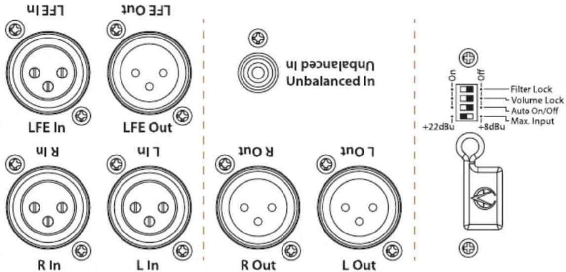
Connections: there are XLR input and output connectors on the rear side that allow the connection of balanced and unbalanced devices (signal sources, active monitors, etc.).
- Balanced XLR pin assignment: 1 = Shield, 2 = hot (+), 3 = cold(-).
- Unbalanced XLR pin assignment: 1 + 3 = Shield, 2 = Signal.
The rear side also offers an unbalanced RCA input connector for the connection to the dedicated Sub out of an EVE Audio SC203 Master/Slave system.
- RCA pin assignment: Sleeve = Shield, Tip = Signal.
Depending on the setting of the Max. Input DIP switch on the rear panel, the maximum level of the source signal should not exceed +8 dBu or +22 dBu (see Max. Input). If the input is overloaded the LED ring will start blinking.
EVE Audio product manual
3.2. Operating Modes
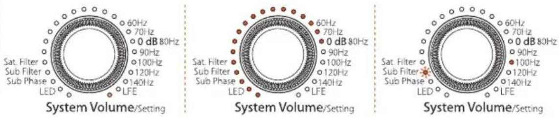
Standby mode | Volume mode (-10 dB) | Settings menu (Sub Filter @ 100 Hz)
3.3. Powering on/off: Standby Mode
Press and hold the System Volume control three seconds in order to put the subwoofer in Standby mode. The total volume (subwoofer + satellites) will decrease gradually while the LED ring lights up once around the System Volume control. Afterwards, the LED on the right end will remain dimly lit and the power consumption is reduced to 1 watt.
To exit the Standby mode press briefly the System Volume control once again. The level will increase gradually until it reaches the previously selected volume.
3.4. Volume Mode
• Level Adjustment
The maximum input level for balanced and unbalanced signals is +8 dBu or +22 dBu, depending on the position of the Max. Input switch on the rear panel (see DIP Switches). Higher levels at the input produce distortion due to the overloading of the analog to digital converter.
Given that some professional studio devices can produce in excess of +22 dBu, the LED ring will start blinking whenever the AD converter is overloading. If that is the case, the output level of the source should be reduced. Generally speaking, the +8 dBu setting ought to be suitable.
Total Volume Adjustment (only when using the XLR ins & outs)
Turn the System Volume control to adjust the total volume (subwoofer + satellites). Depending on the LED mode selected (see LED mode), the volume will be displayed as a dim/bright circle or as a dim/bright point.
In case the subwoofer is connected to an EVE Audio SC203 Master/Slave system via the dedicated RCA Unbalanced in, the System Volume control will affect only the subwoofer volume, not the system volume.
- Subwoofer Volume Adjustment
Turn the Subwoofer Volume control to adjust the volume of the subwoofer
independently from the satellites. This allows you to strike the right balance between subwoofer and satellites. The LED ring indicates the volume setting.
other
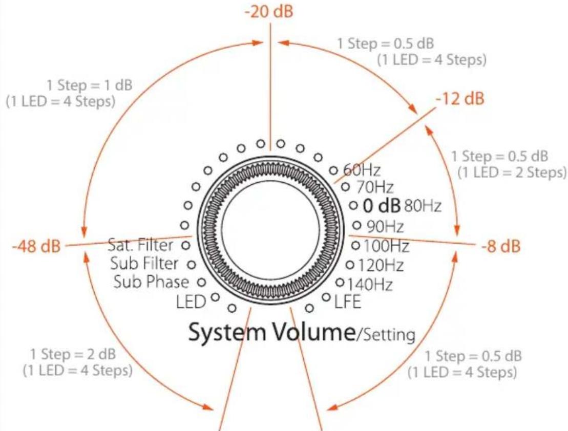
| Parameter | Value | | --------- | ----- | | Frequency | 60Hz | | Power | 70Hz | | Power Ratio | 80Hz | | Power Ratio (Step 1) | 90Hz | | Power Ratio (Step 2) | 100Hz | | Power Ratio (Step 3) | 120Hz | | Power Ratio (Step 4) | 140Hz | | Power Ratio (Step 5) | -8 dB | | Power Ratio (Step 6) | -12 dB | | Power Ratio (Step 7) | -12 dB | | Power Ratio (Step 8) | -20 dB | | Power Ratio (Step 9) | -48 dB | | Power Ratio (Step 10) | -8 dB | | System Volume/Setting | -2 dB | | System Volume/Setting | 0 dB | | System Volume/Setting | 1 dB | | System Volume/Setting | 2 dB | | System Volume/Setting | 4 dB | | System Volume/Setting | 4 Steps |Both controls feature the exact same response curve, which is not linear. The increments become finer as the volume increases:
-80 dB (minimum) to -48 dB: 2 dB
-48 dB to -20 dB: 1 dB
-20 dB to 0 dB (maximum): 0.5 dB
- Subwoofer Mute
To Mute the subwoofer, press briefly the Subwoofer Volume control. All LEDs will turn off, except for the left-most LED, which lights up dimly.
To exit the Subwoofer Mute mode press the Subwoofer Volume control once again. The subwoofer will return to the volume level it had before being muted.
- System Mute (only when using the XLR ins & outs)
To Mute the whole system (subwoofer + satellites), turn the System Volume control counter clockwise until you reach the minimum level. When the LED on the left end of the System Volume control lights up dimly the Mute mode is activated.
EVE Audio product manual
! To exit the System Mute mode simply turn the System Volume control clockwise until you reach the desired volume.
In case the subwoofer is connected to an EVE Audio SC203 Master/Slave system via the dedicated RCA Unbalanced in, the System Volume control will switch the subwoofer to Mute mode but not the satellites.
3.5. Settings Menu
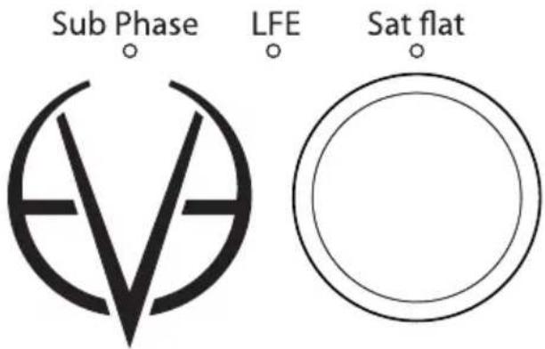
Additional status LEDs on the front panel plus infrared sensor
Press the System Volume control once to enter the Settings menu. Here you can set two different filters (Sat. Filter and Sub Filter), as well as the phase of the subwoofer and the behavior of the volume controls' LED rings. The LED of the currently active function will blink.
Turn the System Volume control to choose the filter, phase or LED mode desired. The blinking LED indicates the function selected, while the steady-on LED indicates the value assigned to that function.
Press the System Volume control to confirm your selection. The blinking will stop once the selection is confirmed.
Turn the System Volume control to adjust the filter, phase or LED behavior. When you are satisfied with the setting press the System Volume control again to go back to the Settings menu. You can then select and edit another function.
To exit the Settings menu press and hold the System Volume control for three seconds or simply wait 10 seconds. The subwoofer will then return automatically to the Volume mode.
3.6. Filter
The filters of the EVE Audio subwoofer were specially developed to offer you the possibility of adjusting your subwoofer to the characteristics of your system. These filters help control the overlapping of frequencies
between the subwoofer and the satellites. The goal is to optimize the sound image to the room acoustics and to a given listening distance.
3.7. Sat. Filter (only when using the XLR ins & outs)
The Sat. Filter is a high-pass filter that can be used to filter out all content below 80 Hz from the L + R outputs going to the satellite speakers. Use this filter to avoid the overlapping of frequencies between the subwoofer and the satellites and to clean up the sound image in the lower end.
Generally speaking, the Sat. Filter should be engaged (default setting). If inactive, for example, when the satellite speakers cannot reproduce the frequency range below 80 Hz, the Sat Flat LED lights on and the audio signal is not filtered.
In case the subwoofer is connected to an EVE Audio SC203 Master/Slave system via the dedicated RCA Unbalanced in, the Sat. Filter will have no effect on the satellites signal.
3.8. Sub Filter
The Sub Filter is a low-pass filter that allows you to set the upper frequency limit of the subwoofer. It can be set from 60 Hz up to 140 Hz. We recommend setting it at 80Hz, but do bear in mind that it might need to be adjusted depending on the room and satellite speakers used.
In LFE mode the cutoff frequency is set to 300Hz. The LFE LED indicates when this filter is activated.
3.9. Sub Phase
This setting allows you to shift 180^ the phase of the subwoofer signal. The Sub Phase LED lights on.
Use this function when the overall sound (subwoofer + satellites) sounds a bit thin. This can happen if the subwoofer's phase is offset from the satellites' due to time differences.
3.10. LED Mode
The LED mode determines in which of the four available fashions the LED rings display the volume level. The LEDs represent given levels, which are displayed and adjusted according to four or two steps. Intermediate steps are indicated by the brightness between two adjacent LEDs.
• Bright Ring
All LEDs up to the selected volume level light up brightly. The louder the
EVE Audio product manual
signal, the longer the brightly lit-up ring.
- Bright Point
Only the LEDs corresponding to the selected volume level light up brightly. The louder the signal, the further up the brightly lit-up point moves.
- Dimly Lit Ring
All LEDs up to the selected volume level light up dimly. The louder the signal, the longer the dimly lit-up ring. In this mode, the LEDs light up brightly momentarily while you adjust the volume level.
- Dimly Lit Point
Only the LEDs corresponding to the selected volume level light up dimly. The louder the signal, the further up the dimly lit-up point moves.
Intermediate steps are indicated by the lighting of two adjacent LEDs. The level ranges from -60 dB to +10 dB, taking "0 dB" as reference point.
3.11. Saving Your Settings
All settings on the front and rear panels are automatically saved. The loudspeakers can be disconnected anytime without the settings being lost.
3.12. Remote Control
Your EVE Audio subwoofer comes with an IR remote control that allows you to control almost all functions available on the front panel.
In order to start using the remote control, you must first insert the supplied batteries in the battery compartment. Please pay attention to the polarity. Hold the remote control in such a way that the infrared cell points towards the receiver cell on the subwoofer. There should be no objects between both cells in order to achieve the best performance.
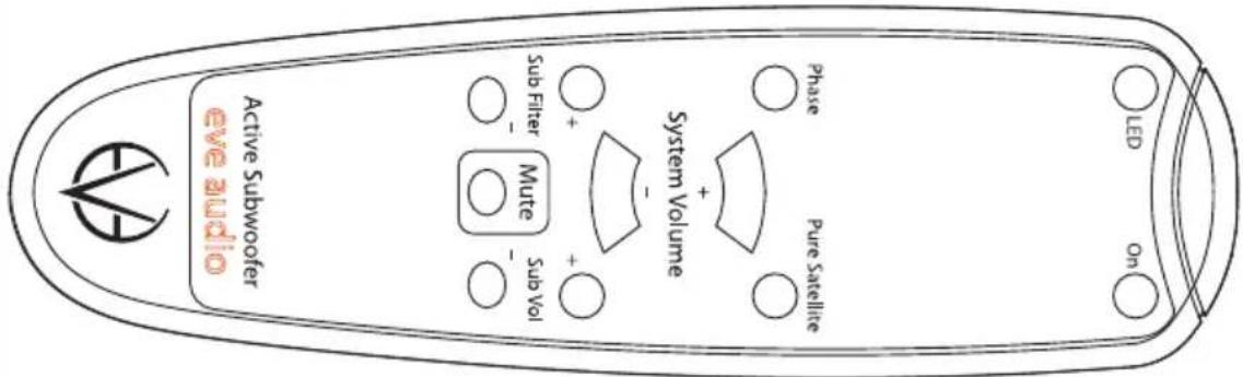
- On Button
Use the On button to put the subwoofer in Standby mode (see Powering
TS107 TS108
On/off: Standy Mode). Press the button again to exit the Standby mode.
- LED Button
Use the LED button to select the LED mode of the subwoofer. The mode changes every time you press the button (bright ring, bright point, dimly lit ring, dimly lit point).
- Phase Button
Press the Phase button to shift 180^ the phase of the subwoofer signal (see Sub Phase). The Sub Phase LED on the subwoofer lights on. Press the button again to return the phase to 0^ .
• Pure Satellite Button
In case the subwoofer is connected via the XLR connections, use the Pure Satellite button to mute the subwoofer (Mute function: see Subwoofer Mute) so that the audio signal is transmitted without any filtering to the satellite speakers. This allows you to switch easily between satellites + subwoofer mode and pure satellite mode (without subwoofer and without any filtering).
In case the subwoofer is connected to an EVE Audio SC203 Master/Slave system via the dedicated RCA Unbalanced in, use the Pure Satellite button to mute the subwoofer (Mute function: see Subwoofer Mute).
• System Volume (+)/(-) Buttons (only when using the XLR ins & outs)
Use the System Volume (+) and (-) buttons to increase or decrease the total volume (subwoofer + satellites).
In case the subwoofer is connected to an EVE Audio SC203 Master/Slave system via the dedicated RCA Unbalanced in, the System Volume (+) and (-) buttons will affect only the subwoofer volume.
- Sub Volume (+)/(-) Buttons
Use the Sub Volume (+) and (-) buttons to increase or decrease the subwoofer volume, and thus balance the level between subwoofer + satellites (see Subwoofer Volume Adjustment).
- Sub Filter (+)/(-) Buttons
Use the Sub Filter (+) and (-) buttons to set the cutoff frequency of the subwoofer's low-pass filter and to select the LFE mode (see Sub Filter).
- Mute Button (only when using the XLR ins & outs)
Press the Mute button to mute the whole system (subwoofer + satellites) (see System Mute). Press the button again to exit the Mute mode.
! In case the subwoofer is connected to an EVE Audio SC203 Master/Slave
EVE Audio product manual
system via the dedicated RCA Unbalanced in, the Mute button will mute the subwoofer but not the satellites.
3.13. Power Switch
The power switch on the rear panel disconnects the subwoofer completely from the power grid. When powered off all settings are saved and the power consumption is reduced to 0 watts.
After powering on again, the subwoofer will return to the state it was in before being turned off (Standby mode, Mute mode or a given volume level). Even if powered off via a multiple outlet power strip, the subwoofer will return to the state it was in before being turned off.
In order to prevent switching noise with your monitoring system, keep in mind the following rules:
Power all audio sources on first, then the subwoofer and then the satellites. When turning off your system, power off the satellites first, then the subwoofer and finally all audio sources.
3.14. DIP Switches
On the rear panel of your EVE Audio subwoofers you will find four DIP Switches. These allow you to secure your subwoofer settings to prevent them from being changed inadvertently.
- Filter Lock
When set to "On," this DIP Switch secures the current filter settings. The filter settings can be read on the LED ring of the System Volume control on the front panel, but they cannot be modified. When set to "Off," the filters can be modified freely.
• Volume Lock
When set to "On" this DIP Switch secures the current volume settings. The LED rings on the front panel indicate the volume settings of the subwoofer and the satellites (connected to the subwoofer via the XLR outs), but they cannot be modified. When set to "Off," the volume setting can be changed by simply turning the knob.
• Auto On/Off
When set to "On", this DIP Switch enables the auto-standby mode. This function automatically switches the subwoofer to standby when no input signal was detected for 10 min in both XLR and RCA inputs. The system is automatically switched on again as soon as an input signal is detected
TS107 TS108
either in the XLR ins or the RCA in.
! To exit the Standby mode press briefly the System Volume control or push the On button on the remote control.
• Max. Input
This DIP Switch determines the input sensitivity of the subwoofer. In a studio environment, the maximum level (0 dB) ought to be 4 dBu. In such environments, leave the setting at "+8dBu." However, some studio gear allow much higher output levels. If it were impossible to reduce the output level of such devices, set the switch to "+22dBu."
The "+8dBu" setting ought to be suitable for most situations.
3.15. Power Connector (IEC)
Use the power cord supplied to connect your EVE Audio subwoofer to the power grid. The IEC connector includes an integrated fuse. If your EVE Audio loudspeaker stops working and the fuse seems to be the problem, proceed as follows:
- Turn the subwoofer off.
- Disconnect it from the power grid.
- Detach the IEC connector from the unit.
- Remove the fuse.
- Change the fuse. The replacement fuse should comply with the values stated on the subwoofer.
4. POSITIONING
4.1. Subwoofer Positioning
Ideally, there should be no objects or obstacles between the subwoofer and the listening position. We recommend to keep a distance of at least 0.5 m (19 inches) to the walls, in order to avoid low frequency boosting.
4.2. Height and Distance
Your EVE Audio subwoofer should be placed on the floor. The surface where it stands ought to be as firm and stable as possible, in order to prevent surface vibrations from generating unwanted resonances.
The distance from subwoofer to listening spot depends on the position of the satellites. Ideally, the subwoofer and satellites should be at the same distance from the listener. In a 2.1 system the subwoofer ought to be placed between both satellites (see Stereo Setup + Subwoofer). In a 5.1
EVE Audio product manual
system the subwoofer ought to be placed between the two front satellites (see Multichannel Setup).
| Room area in m^2 (sq ft) | Room volume in m^3 (cu ft) | Recommended subwoofer | Recommended Satellites: 2.1 Setup | Recommended Satellites: 5.1 Setup |
| up to 15 (161) | up to 40 (1412) | TS107 | SC203, SC204, SC205 | SC204 |
| 15 to 20 (162 to 215) | 40 to 50 (1412 to 1766) | TS108 | SC203, SC205, SC207, SC305 | SC204, SC205 |
These values are only meant as a reference and depend a lot on the characteristics of the room. In live rooms you will be forced to reduce the distance, while in dead rooms the distance to the loudspeakers can be larger.
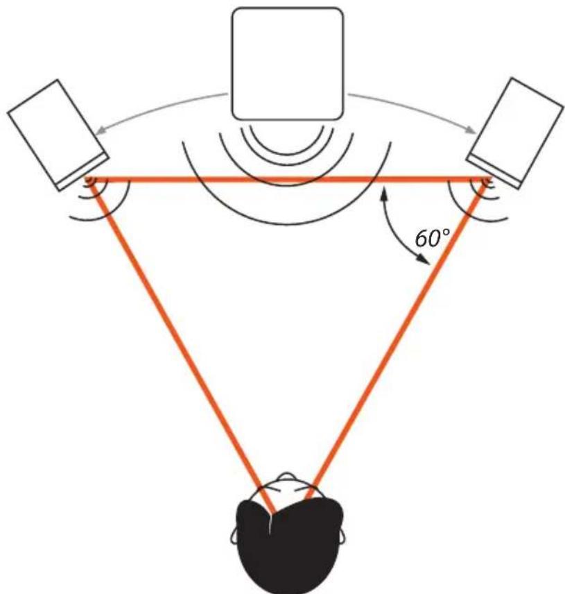
4.3. Stereo Setup + Subwoofer (2.1)
In case the subwoofer is connected via the XLR ins and outs, it is fed by the stereo signal source. The subwoofer filters the low frequency components of the stereo channels and sums them to produce a mono signal, which it then reproduces. The high frequencies are forwarded to the full-range satellite speakers.
In case the subwoofer is connected to an EVE Audio SC0203 Master/Slave system via the dedicated RCA Unbalanced in, it is fed by the signal of the Master satellite Sub out. This low-frequency mono signal is filtered by the SC203 system.
Refer to the table above to determine the best 2.1 setup for your room.
The so-called "stereo triangle" is the best way to place the satellites in a stereo setup, i.e. the monitors and the listening position should form an equilateral triangle. Try the following:
- Establish the ideal distance to the listening position.
Place the monitors in such a way that the distance from each other and to the listening position is the same.
Turn both monitors so that their front panels are pointed towards the listening position (all angles of the stereo triangle should be 60°).
The subwoofer should be placed on the ground between both satellites. Considering that low frequencies are omnidirectional, the subwoofer does not have to be centered exactly between the two satellites. The subwoofer can be moved back a bit so that it is at the same distance from the listening position as the satellites. This guarantees all transducers are aligned in time.
4.4. Multichannel Setup (5.1)
The most common 5.1 systems consist of three front channels (left, right and center), two surround channels (left/right) and a subwoofer for the low frequencies. The speakers form a circle around the listening position.
EVE Audio product manual
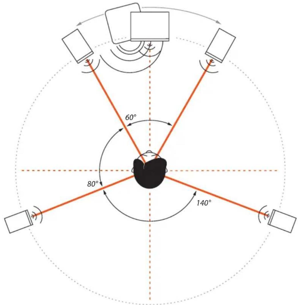
Refer to the table above to determine the best 5.1 setup for your room.
The positioning of the two front speakers and the subwoofer should be done in the same manner as in a stereo setup with a subwoofer (see "Stereo Setup + Subwoofer").
Place the center monitor directly in front of the listening position, i.e. right in the center between both front satellites.
The rear satellites should form an isosceles triangle with the listening position forming an angle of 140^ .
Verify that all speakers are at the same distance from the listening position, so that they are aligned in time.
4.5. Room Acoustics
In order for the described measures to work effectively, we recommend that you put special attention to the room acoustics. The size, contents,
TS107 TS108
wall parallelism, proportion, and reflective behavior of the room, as well as the corners, the building materials and their characteristics play a very important role in the acoustics of a room.
Room acoustics is a science in itself and it is unfortunately out of the scope of this manual. However, we have put together a short bibliography for you:
"Recording Studio Design" by Philip Newell. ISBN: 0-240-51917-5
"Home Recording Studio – Build it like the Pros" by Rod Gervais. ISBN: 1-59863-034-2
"Studio Akustik" (in German) by Andreas Friesecke. ISBN: 978-3-932275-81-4
| Description Subwoofer Subwoofer | ||
| Dimensions (WxHxD) (mm) 230 x 355 x 300 280 x 415 x 365 | ||
| Dimensions (WxHxD) (“) 9.06 x 13.98 x 11.81 11.02 x 16.34 x 14.37 | ||
| Frequency Range (-3dB) | 33 - 300Hz(LFE Mode) | 29 - 300Hz(LFE Mode) |
| Woofer 165mm / 6.5” 195mm / 8” | ||
| Maximum SPL @ 1m 102dB | 105dB | |
| Number of Amplifiers | 1 | 1 |
| Output Power (short term) | 100W | 150W |
| Limiter | Yes | Yes |
| Setting Options | ||
| System Volume (Sub + Sat.) | -inf. - +6dB | -inf. - +6dB |
| Subwoofer Volume | -inf. - +6dB | -inf. - +6dB |
| Switchable Sat. Filter | Flat / 80Hz | Flat / 80Hz |
| Variable Subwoofer Filter | 60-140Hz+ LFE Mode | 60-140Hz+ LFE Mode |
| Volume Lock | Yes | Yes |
| Filter Lock | Yes | Yes |
| Auto-standby Switch | Yes | Yes |
| Phase Switch | 0^/180^ | 0^/180^ |
| Input Level Switch | +8dBu / +22dBu | +8dBu / +22dBu |
| Remote Control | IR | IR |
| Connections | ||
| Balanced XLR Inputs(impedance) | L In + R In (10kΩ) | L In + R In (10kΩ) |
| Balanced XLR Outputs(impedance) | L Out + R Out (10kΩ) | L Out + R Out (10kΩ) |
| Balanced LFE Connections(impedance) | LFE In + LFE Out(10kΩ) | LFE In + LFE Out(10kΩ) |
| Unbalanced RCA Input(impedance) | Unbalanced In(10kΩ) | Unbalanced In(10kΩ) |
| Power Consumption | ||
| Standby | < 1W | < 1W |
| Maximum | 120VA | 170VA |
| Miscellaneous | ||
| Weight kg / lb. | 8.2 / 18.1 | 11.5 / 25.3 |
6. COMPLIANCE
We,
EVE Audio GmbH,
with registered office in
Ernst Augustin Str. 1a, 12489 Berlin, Germany,
herewith declare that the
TS107 and TS108
comply with the following norms:
EC Norms:
EN 60065: 2002 + A1:2006 + A11:2008 + A2:2010 + A12:2011
EN 50564: 2011
EN 62301: 2005
EMC Norms:
EN 55013: 2013
EN 55020:2007+A11:2011
EN 6100-3-2: 2014
EN 6100-3-3: 2013
IEC 61000-4-2 ED. 2.0: 2008
IEC 61000-4-4 ED. 3.0: 2012
This declaration certifies that the quality control and product documentation complies with the current corresponding EU directives.
Federal Communications Commission interference statement
This equipment has been tested and found to comply with the limits for a Class B digital device, pursuant to part 15 of the FCC Rules. These limits are designed to provide reasonable protection against harmful interference in a residential installation. This equipment generates, uses and can radiate radio frequency energy and, if not installed and used in accordance with the instructions, may cause harmful interference to radio communications. However, there is no guarantee that interference will not occur in a particular installation. If this equipment does cause harmful interference to radio or television reception, which can be determined by turning the equipment off and on, the user is encouraged to try to correct the interference by one or more of the following measures:
- Reorient or relocate the receiving antenna.
- Increase the separation between the equipment and receiver.
- Connect the equipment into an outlet on a circuit different from that to which the receiver is connected.
- Consult the dealer or an experienced radio/ TV technician for help.
EVE Audio product manual
Caution:
Any changes or modifications not expressly approved by the grantee of this device could void the user's authority to operate the equipment.
Canada, Industry Canada (IC) Notices
This Class B digital apparatus complies with Canadian ICES-003.
Operation is subject to the following two conditions: (1) this device may not cause interference, and (2) this device must accept any interference, including interference that may cause undesired operation of the device.
Canada, avis d'Industry Canada (IC)
Managing Director EVE Audio
7. WARRANTY
The manufacturer warranty is valid for a period of two (2) years after the date of purchase.
The warranty covers repair costs (labor and spare parts), product replacement if applicable, and return transport within the country where the product was bought.
The warranty will be void if any of the following applies:
• Damages have been caused by incorrect installation and/or connection,
- Damages have been caused by misuse or negligence,
- The unit has been tampered with or modified in any way,
- The unit has been repaired or modified by unqualified personnel,
• Damages have been caused by factors beyond the reasonable control of EVE Audio (lightning, fire, flood, etc.)
Always keep the original packaging of any EVE Audio product: Only products with original packaging are eligible for warranty service. If the product is not packaged in its original box, EVE Audio will not be liable for any damages occurred during transit.
Should service be required during or after the warranty period, please contact your local EVE Audio dealer or distributor.

natural_image
Abstract geometric symbol resembling a stylized 'V' within a circle, no text or labels present.EVE AUDIO GmbH
合. Ernst Augustin Str. 1a, 12489 Berlin, Germany
. +49-30-6704 4180
. +49-30-6704 4188
@. info@eve-audio.com
www.eve-audio.com
f.facebook.com/EveAudio
. twitter.com/EveAudio
- SAFETY INSTRUCTIONS
- EVE Audio product manual
- TABLE OF CONTENT
- INTRODUCTION 6
- QUICK START....7
- OPERATION 8
- POSITIONING ....16
- TECHNICAL SPECIFICATIONS....21
- COMPLIANCE....22
- WARRANTY....23
- INTRODUCTION
- QUICK START
- First Steps
- Subwoofer Connection
- Powering On
- OPERATION
- First Steps
- Operating Modes
- Powering on/off: Standby Mode
- Volume Mode
- • Level Adjustment
- Total Volume Adjustment (only when using the XLR ins & outs)
- - Subwoofer Volume Adjustment
- - Subwoofer Mute
- - System Mute (only when using the XLR ins & outs)
- Settings Menu
- Filter
- Sat. Filter (only when using the XLR ins & outs)
- Sub Filter
- Sub Phase
- LED Mode
- • Bright Ring
- - Bright Point
- - Dimly Lit Ring
- - Dimly Lit Point
- Saving Your Settings
- Remote Control
- - On Button
- TS107 TS108
- - LED Button
- - Phase Button
- • Pure Satellite Button
- • System Volume (+)/(-) Buttons (only when using the XLR ins & outs)
- - Sub Volume (+)/(-) Buttons
- - Sub Filter (+)/(-) Buttons
- - Mute Button (only when using the XLR ins & outs)
- Power Switch
- DIP Switches
- - Filter Lock
- • Volume Lock
- • Auto On/Off
- • Max. Input
- Power Connector (IEC)
- POSITIONING
- Subwoofer Positioning
- Height and Distance
- Stereo Setup + Subwoofer (2.1)
- Multichannel Setup (5.1)
- Room Acoustics
- COMPLIANCE
- EVE Audio GmbH,
- TS107 and TS108
- EC Norms:
- EMC Norms:
- Federal Communications Commission interference statement
- Caution:
- Canada, Industry Canada (IC) Notices
- Canada, avis d'Industry Canada (IC)
- WARRANTY
- EVE AUDIO GmbH
Brand : EVE Audio
Model : TS108
Category : Subwoofer