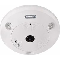
TVIP86900 - Surveillance Camera ABUS - Free user manual and instructions
Find the device manual for free TVIP86900 ABUS in PDF.


| Product Type | Outdoor IP Surveillance Camera |
| Brand | ABUS |
| Model | TVIP86900 |
| Dimensions (L x W x H) | 180 x 70 x 70 mm |
| Weight | 500 g |
| Power Supply | PoE (802.3af) or 12 V DC power adapter |
| Power Consumption | 8 W max |
| Resolution | Full HD 1080p (1920 x 1080 pixels) |
| Night Vision | Up to 30 m with IR LED |
| Viewing Angle | 90° (diagonal) |
| Motion Detection | Yes, adjustable via app |
| Two-way Audio | Yes, built-in microphone and speaker |
| Storage | MicroSD up to 128 GB or NAS |
| Connectivity | Ethernet 10/100 Base-T |
| Supported Protocols | ONVIF, RTSP, HTTP, HTTPS |
| Protection Rating | IP66 (weather-resistant) |
| Operating Temperature | -20 °C to 50 °C |
| Mounting | Wall or bracket mount (included) |
| Maintenance and Cleaning | Clean the lens with a soft, lint-free cloth. Do not use chemicals. |
| Security | SSL/TLS encryption, password authentication, firmware updates |
| Spare Parts and Repairability | Power adapter, Ethernet cable, mounting brackets, sealing gasket kit |
| General Information | ABUS TVIP86900 outdoor IP camera, compatible with ABUS Link Station app and ABUS NVRs |
Frequently Asked Questions - TVIP86900 ABUS
User questions about TVIP86900 ABUS
0 question about this device. Answer the ones you know or ask your own.
Ask a new question about this device
Download the instructions for your Surveillance Camera in PDF format for free! Find your manual TVIP86900 - ABUS and take your electronic device back in hand. On this page are published all the documents necessary for the use of your device. TVIP86900 by ABUS.
USER MANUAL TVIP86900 ABUS
These user manual contains important information for installation and operation.
This should be also noted when this product is passed on to a third party.
Therefore look after these operating instructions for future reference!
A list of contents with the corresponding page number can be found in the index on page 73.
Français
Bedienungsanleitung
Version 12/2014
CE
① Cat5 Ethernetkabel
100M Full-dup; 10M/100M/1000M Auto
DHCP
Konto-Informationen hinterlegen:
DynDNS.com

Trap-Community: TRAP-Community String
SNMP v3
User manual
Version 12/2014
CE
English translation of the original German user manual. Retain for future reference.
Introduction
Dear Customer,
Thank you for purchasing this product.
This device complies with the requirements of the applicable EU directives. The declaration of conformity can be obtained from:
To ensure this condition is maintained and that safe operation is guaranteed, it is your obligation to observe this user manual.
Read the entire user manual carefully before putting the product into operation, and pay attention to all operating instructions and safety information.
All company names and product descriptions are trademarks of the corresponding owner. All rights reserved.
If you have any questions, please contact your specialist installation contractor or specialist dealer.

Disclaimer
This user manual has been produced with the greatest of care. Should you discover any omissions or inaccuracies, please contact us in writing under the address provided on the back of the manual.
ABUS Security-Center GmbH & Co. KG does not accept any liability for technical and typographical errors, and reserves the right to make changes to the product and user manuals at any time and without prior warning.
ABUS Security-Center GmbH is not liable or responsible for direct or indirect damage resulting from the equipment, performance and use of this product. No forms of guarantee are accepted for the contents of this document.
Explanation of symbols
 | The triangular high voltage symbol is used to warn of the risk of injury or health hazards (e.g. caused by electric shock). |
 | The triangular warning symbol indicates important notes in this user manual which must be observed. |
 | This symbol indicates special tips and notes on the operation of the unit. |
Important safety information
 | All guarantee claims are invalid in the event of damage caused by non-compliance with this user manual. We cannot be held liable for resulting damage. |
 | In the event of material or personal damage caused by improper operation or non-compliance with the safety information, we cannot be held liable. All guarantee claims are void in such cases. |
The following safety information and hazard notes are not only intended to protect your health, but also to protect the device from damage. Please read the following points carefully:
- There are no components inside the product that require servicing. Dismantling the product invalidates the CE certification and the guarantee/warranty.
- The product may be damaged if it is dropped, even from a low height.
- Install the device so that the image sensor is not exposed to direct sunlight. Pay attention to the installation instructions in the corresponding section of this user manual.
- This device is designed for indoor use or for use in weatherproof housing.
Avoid the following adverse conditions during operation:
- Moisture or excess humidity
• Extreme heat or cold - Direct sunlight
- Dust or flammable gases, vapours or solvents
• Strong vibrations
• Strong magnetic fields (e.g. next to machines or loudspeakers) - The camera must not be installed on unstable surfaces.
General safety information:
- Do not leave packaging material lying around. Plastic bags, sheeting, polystyrene packaging, etc. can pose a danger to children if played with.
- The video surveillance camera contains small parts which could be swallowed and should be kept out of reach of children for safety reasons.
- Do not insert any objects into the device through the openings.
- Only use replacement devices and accessories that are approved by the manufacturer. Do not connect any non-compatible products.
- Please pay attention to the safety information and user manuals for the other connected devices.
- Check the device for damage before putting it into operation. Do not put the device into operation if you detect any damage.
- Adhere to the operating voltage limits specified in the technical data. Higher voltages could destroy the device and pose a health risk (electric shock).
Safety information
- Power supply: Power supply unit 100–240 V AC, 50/60 Hz / 12 V DC, 1 A (included in the scope of delivery). Only operate this device through a power source which supplies the mains power specified on the type plate. If you are unsure of the installation location's power supply, contact your power supply company. Disconnect the device from the power supply before carrying out maintenance or installation work.
2. Overloading
Avoid overloading electrical sockets, extension cables, and adapters, as this can result in fires or electric shocks.
3. Cleaning
Only use a damp cloth to clean the device. Do not use corrosive cleaning materials. Disconnect the device from the power supply before cleaning.
Warnings
Observe all safety and operating instructions before putting the device into operation for the first time.
-
Observe the following information to avoid damage to the power cable and plug:
-
Do not modify or manipulate the power cable or plug.
- Do not bend or twist the power cable.
- Do not pull the cable when disconnecting the device from the power – always take hold of the plug.
-
Ensure that the power cable is positioned as far away as possible from any heating equipment, as this could otherwise melt the plastic coating.
-
Follow these instructions. Non-compliance with these instructions could lead to an electric shock:
-
Never open the housing or power supply unit.
- Do not insert any metallic or flammable objects into the device.
-
Use surge protection to prevent damage caused by overvoltage (e.g. in electrical storms).
-
Disconnect defective devices from the power immediately and contact your specialist dealer.
| When installing the device in an existing video surveillance system, ensure that all devices have been disconnected from the mains power circuit and low-voltage circuit. | |
| If in doubt, have a specialist technician carry out assembly, installation and connection of the device. Improper or unprofessional work on the power supply system or domestic installation puts both you and other persons at risk.Connect the installations so that the mains power circuit and low-voltage circuit always run separatelyfrom each other. They should not be connected at any point or become connected as a result of a malfunction. |
Unpacking the device
Handle the device with extreme care when unpacking it.
| If the original packaging has been damaged, you must start by inspecting the device. If the device shows signs of damage, return it in the original packaging and inform the delivery service. |
Contents
- Intended use 75
- Scope of delivery....75
- Features and functions....75
- Device description 75
- Description of the connections....76
- Initial start-up....77
- Accessing the network camera for the first time....78
- Password prompt....79
- User functions 80
9.1 Menu bar 80
9.2 Live image display....81
9.3 Audio/video control....81
9.4 Live view mode....81
9.5 PTZ control....82
9.5.1 Preset settings....82
9.6 Patrol settings....83
- Configuration....84
10.1 Local configuration 84
10.2 Basic configuration....86
10.3 Advanced configuration....86
10.3.1 System 86
10.3.1.1 Device information 87
10.3.1.2 Time settings....88
10.3.1.3 Maintenance....89
10.3.1.4 Daylight saving time 90
10.3.1.5 Fisheye parameters 91
10.3.2 Network 92
10.3.2.1 TCP/IP....93
10.3.2.2 Port 95
10.3.2.3 DDNS 96
10.3.2.4 PPPoE 99
10.3.2.5 SNMP 99
10.3.2.6 802.1X....101
10.3.2.7 QoS....101
10.3.2.8 FTP 102
10.3.2.9 UPnP TM 103
10.3.2.10 Email....104
10.3.2.11 NAT....105
10.3.3 Video/Audio 107
10.3.3.1 Video 108
10.3.3.2 Audio 110
10.3.3.3 ROI 'Region of Interest' 111
10.3.4 Image 112
10.3.4.1 Display settings.... 113
10.3.4.2 OSD Settings 116
10.3.4.3 Privacy Mask 117
10.3.5 Security 118
10.3.5.1 User 118
10.3.5.2 RTSP Authentication 120
10.3.5.3 IP Address Filter.... 120
10.3.6 Basic event 121
10.3.6.1 Motion detection 121
10.3.6.2 Video tampering....123
10.3.6.3 Alarm input (TVIP83900 only) 125
10.3.6.4 Alarm output (TVIP83900 only)....127
10.3.8 Storage....129
10.3.8.1 Record schedule 129
10.3.8.2 Storage management .... 131
10.3.8.3 NAS.... 132
10.3.8.4 Snapshot....133
- Maintenance and cleaning....134
11.1 Maintenance.... 134
11.2 Cleaning 134
-
Disposal....134
-
Technical data.... 135
-
GPL license information 136
1. Intended use
The hemispheric IP dome camera enables high-quality monitoring. The advantage of this camera is that it can be used to replace up to five cameras. In addition to the fisheye view, the other video channels – up to a maximum of five – allow further views to be set separately. These additional views can be made to pan, tilt or zoom electronically. Recordings can be stored on an optional SD card, which allows footage to be played back directly via the web interface.
2. Scope of delivery
 |  |  |  |
| Hemispheric IP dome camera | CD | Quick start guide | Installation material |
3. Features and functions
- 360° / 180° panorama views with up to 6 MPx resolution
- Simple design and high protection class (IP66) (TVIP86900 only)
• Digital, stageless panning, tilting or zooming without mechanical camera movement
• Freely configurable patrols (panning/tilting)
• Power over Ethernet (PoE) - Up to 25 fps real-time video
4. Device description
| Model number TVIP83900 TVIP86900 | ||
| Resolution 3 MPx | 6 MPx | |
| WDR | - | |
| Audio √ | - | |
| I/O √ | - | |
| IP66 | - | |
√
√
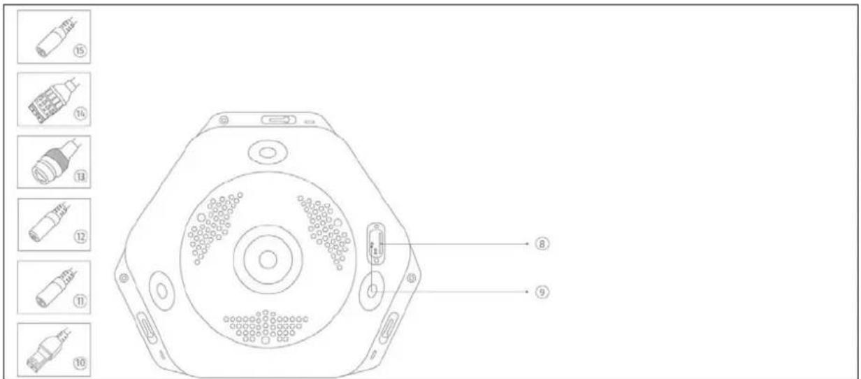
5. Description of the connections

| No | Description |
| 1 | Camera cover |
| 2 | Screw to release cover |
| 3 | Photo sensor |
| 4 | Lens |
| 5 | IR LEDs |
| 6 | Microphone (only in TVIP83900) |
| 7 | Loudspeaker (only in TVIP83900) |
 |
6. Initial start-up
The network camera automatically detects whether a direct connection between the PC and camera should be established. A crossover network cable is not required for this. You can use the supplied patch cable for direct connection for initial start-up.
Connecting the network camera directly to a PC/laptop
- Ensure that a CAT 5 network cable is used.
- Connect the cable to the Ethernet interface of the PC/laptop and the network camera.
- Connect the network camera to the power supply.
- Configure the network interface of your PC/laptop to the IP address 192.168.0.2 and the default gateway to 192.168.0.1.
- Proceed to point 8 to finish the initial set-up and establish the connection to the network camera.

① CAT 5 Ethernet cable
Connecting the network camera to a router/switch
- Ensure that a CAT 5 network cable is used.
- Connect the PC/laptop to the router/switch.
- Connect the network camera to the router/switch.
- Connect the network camera to the power supply.
- If a DHCP server is available on your network, set the network interface of your PC/laptop to 'Obtain an IP address automatically'.
- If no DHCP server is available, configure the network interface of your PC/laptop to 192.168.0.2 and the default gateway to 192.168.0.1.
- Proceed to point 8 to finish the initial set-up and establish the connection to the network camera.
![graph TD A["Laptop"] --> B["Router"] B --> C["CD/DVD Device"] C --> D["Internet"] style D fill:#f9f,stroke:#333](/content/2026/06/1271100/images/25674eeb9f458bb8aa61b532f15faf8742da192584e7d30041a8892ac574241e.jpg)
7. Accessing the network camera for the first time
The network camera is accessed for the first time using the ABUS IP Installer.
After the installation wizard is started, it searches for all connected ABUS network cameras and video servers on your network.
You can find the program on the CD-ROM included. Install the program on your PC and then run it.
If a DHCP server is available on your network, the IP address is assigned automatically for both the PC/laptop and the network camera.
If no DHCP server is available, the network camera automatically sets the following IP address: 192.168.0.100.
Your PC system must be located in the same IP sub network to establish communication with the network camera (PC IP address: e.g. 192.168.0.2).


The default setting for the network camera is 'DHCP'. If no DHCP server is in operation on your network, we recommend setting the IP address manually to a fixed value following initial access to the network camera.
8. Password prompt
An administrator password is defined for the network camera prior to delivery. For reasons of security, however, the administrator should select a new password immediately. After the new administrator password has been saved, the network camera asks for the user name and password every time it is accessed.
The administrator account is set up in the factory as follows: user name 'admin' and password '12345'. Each time the network camera is accessed the browser displays an authentication window and asks for the user name and password. Should your individual settings for the administrator account no longer be accessible, please contact our technical support team.
To enter a user name and password, proceed as follows:
Open Internet Explorer and enter the IP address of the camera (e.g. 'http://192.168.0.100').
You will then be presented with the following authentication prompt:
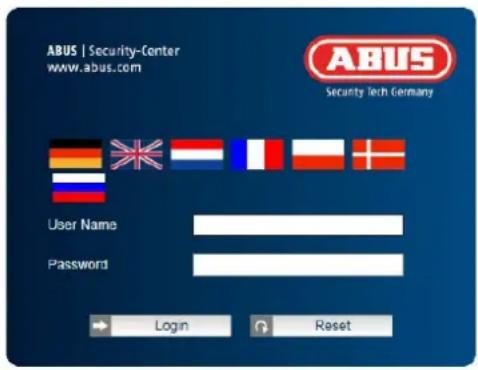
-> You are now connected to the network camera and can see a video stream.
9. User functions
Open the network camera home page. The interface is divided into the following main areas:

9.1 Menu bar
Select the appropriate tab: 'Live View', 'Playback', 'Configuration' and Log. (Log function is only possible with built in micro SD card).
| Button Description | |
| Display of the user logged on | |
| User logout |
9.2 Live image display
You can access the full-screen view by double-clicking.
| Button Description | |
 | Activate 4:3 view |
 | Activate 16:9 view |
 | Display original size |
 | Automatically adjust view to browser |
9.3 Audio/video control
| Button | Description |
 | Disable live view |
 | Enable live view |
 | Disable/enable audio, adjust volume (TVIP83900) |
 | Microphone on/off (TVIP83900) |
 | Instant image (snapshot) |
 | Start/stop manual recording |
 | Digital zoom |
9.4 Live view mode
 | The availability of the options in the live view differs according to whether real-time mode is enabled or disabled (Configuration/System/Fisheye Parameters).The |
| Button | Description | Available in mode |
| Fisheye View | 360-degree mode in full-screen display | Real-time Mode/Normal Mode |
| Panorama View Quadrants are summarised in two panorama halves | Normal Mode | |
| Fisheye+3 PTZ One quadrant displays the 360° fisheye image, the other three quadrants are displayed as virtual PTZ cameras | Normal Mode | |
| Panorama+3 PTZ One quadrant displays the panorama image, the other three quadrants are displayed as virtual PTZ cameras | Normal Mode | |
| 4 PTZ Views Four quadrants as virtual PTZ cameras Real-time Mode | ||
9.5 PTZ control
To display the PTZ control, click on the field in the live view.
| Button Description | |
 | Arrow buttons:Control the swivel/tilt motions Start/stop 360° rotation Start/stop 360° rotation |
| Zoom in/out | |
| Adjust the PTZ speed |
9.5.1 Preset settings
Select the Preset tab 📁 to be able to call up, set and delete up to 256 preset positions. Use the PTZ control buttons to select the desired position.
Click on the button to save the preset.
| Button Description | ||
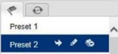 | Select the desired preset position. The selected position has a blue background | |
 | Call up the position | |
| Create the position | ||
| Delete the position | ||

9.6 Patrol settings

A patrol consists of a series of presets. You can create up to 8 patrols, each with up to 32 presets.

Please note that the presets that should be added to a patrol are predefined.
To create a new patrol, proceed as follows:
Select the Patrol tab . Select the desired patrol. To add presets to the patrol, click on the button.
Select the desired preset and set the patrol duration and speed.

| Patrol duration Dwelling time | at a preset position. After the time has elapsed, the camera switches to the next preset |
| Patrol speed Set the speed of motion to the next preset | |
| Button Description | |
| Select the desired patrolThe patrol is reset by clicking on the ✗ button for preset 1 | |
| 3 Preset3 5s 20 | Added preset position with patrol duration and patrol speed |
| Start patrol | |
| Stop patrol | |
| Save patrol | |
| Delete the preset position; doing this for preset 1 will delete the entire patrol |
10. Configuration
10.1 Local configuration
Under the 'Local Configuration' menu item, you can select settings for the live view, file paths of the recordings and snapshots.

Live view parameters
Here you can set the protocol type and the live view performance of the camera.
Protocol
TCP: Complete provision of streaming data and high video quality; however, this affects real-time transmission is affected.
UDP: Real-time audio and video transmission.
MULTICAST: Use of the multicast protocol (the network components must support multicast). Additional multicast settings can be found under Configuration/Network.
HTTP: Provides the same quality as TCP; however, special ports are not configured under the network settings.
Live view performance
You can set the performance level for the live view here.
Rules
As soon as this function has been enabled, a frame will be displayed around the triggered area in the live image for used and triggered motion detection.
Image format
Setting of the format in which the single frame from the live view (Instant image button) should be saved (JPEG, BMP).
Recording file settings
You can define the file size for recordings, the recording path and the path for downloaded files here. To apply the changes, click 'Save'.
Recording file size
You can choose between 256 MB, 512 MB and 1 GB as the file size for recordings and downloaded videos.
Save record files to
You can determine the file path that is to be used for manual recordings here.
The default path is C:\
Save downloaded files to
You can store the file path for downloaded videos here.
The following path is set by default: C:\
Image save settings
Here you can store the path for instant images, snapshots taken during playback as well as for edited videos.
Save snapshots in live view to
Select the file path for instant images from the live view.
The following path is set by default: C:\
Save snapshots during playback to
You can store the path here for saving snapshots taken during playback.
The following path is set by default: C:\
Save clips to
You can specify the save path for storing edited video clips here.
The following path is set by default: C:\
10.2 Basic configuration
All settings located under 'Basic Configuration' can also be found under the menu item 'Advanced Configuration'. Please note the 'Available in mode' column in the descriptions of the 'Advanced Configuration'.

10.3 Advanced configuration
10.3.1 System

| Menu item Description | Available in mode | |
| Device Information | Display of device information | Basic Configuration, Advanced Configuration |
| Time Settings | Configuration of the time specification | Basic Configuration, Advanced Configuration |
| Maintenance | Configuration of system maintenance settings | Basic Configuration, Advanced Configuration |
| RS485 | Not used - | |
| Daylight saving time | Configuration of the automatic daylight saving time switch | Advanced Configuration |
| Fisheye Parameters | Configuration of real-time mode on/off and wall/table/ceiling installation | Advanced Configuration |
10.3.1.1 Device information
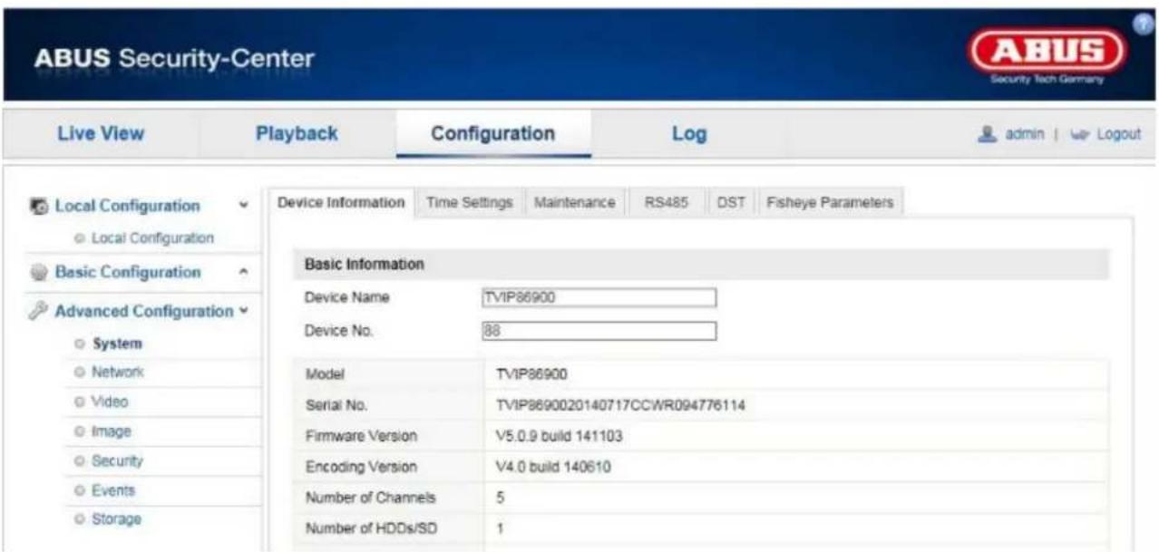
Basic Information
Device Name:
You can specify a device name for the Speed Dome here. Click on 'Save' to apply the change.
Model:
Model number display
Serial Number:
Serial number display
Firmware Version:
Firmware version display
Encoding Version:
Encoding version display
Number of Channels:
Display of the number of channels
Number of HDDs/SDs:
Number of installed storage media (SD card, max. one)
Number of Alarm Input:
Display of the number of alarm inputs
Number of Alarm Output:
Display of the number of alarm outputs
10.3.1.2 Time settings
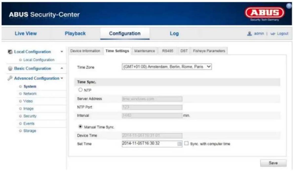
Time Zone
Time zone selection (GMT).
Time Sync.
NTP
Using the Network Time Protocol (NTP) it is possible to synchronise the time of the Speed Dome with a time server.
Enable NTP to use this function.
Server Address
IP server address of the NTP server.
NTP Port
Network port number of the NTP service (default: port 123).
Manual Time Sync.
Device Time
Computer device time display.
Set Time
Display of the current time using the time zone setting.
Click on 'Sync. with computer time' to adopt the device time of the computer.
 | Apply the settings by clicking 'Save'. |
Reboot
Click 'Reboot' to restart the device.
Default
Restore
Click 'Restore' to restore all the parameters to default settings, except the IP parameters and user information.
Default
Select this item to restore all parameters to default settings.
Import Config. File
Config File
Select a file path to import a configuration file here.
Status
Display of the import status.
Export Config. File
Click 'Export' to export a configuration file.
Remote Upgrade
Firmware
Select the path to update the Speed Dome with new firmware.
Status
Display of the upgrade status.

Apply the settings by clicking 'Save'.
10.3.1.4 Daylight saving time

Daylight saving time
Enable DST
Activate the 'Enable DST' checkbox to adjust the system time automatically to daylight saving time.
Start Time
Specify the time for switching to daylight saving time.
End Time
Specify the time for switching to standard time.

Apply the settings by clicking 'Save'.
10.3.1.5 Fisheye parameters
Real-time Mode:
When Real-time Mode is enabled, the Fisheye View can be displayed with up to 25 frames/second (when Real-time Mode is disabled, this is known as Normal Mode). However, when Real-time Mode is enabled, not all live view options are available.
TVIP83900
Resolutions available:
Real-time Mode: Fisheye (2048x2048, 1280x1280), PTZ (1024x768, 704x576, 640x480, 320x240)
Normal Mode: Fisheye (1536x1536), PTZ (800x600, 704x576, 640x480, 320x240), Panorama (1600x1200, 1280x720)
Live view options available:
Real-time Mode: Fisheye View, 4 PTZ views
Normal Mode: Fisheye View, Panorama View, Fisheye+3 PTZ, Panorama+3 PTZ
TVIP86900
Resolutions available:
Real-time Mode: Fisheye (3072x2048, 2048x2048, 1280x1280), PTZ (1024x768, 704x576, 640x480, 320x240)
Normal Mode: Fisheye (1280x1280), PTZ (1024x768, 704x576, 640x480, 320x240), Panorama (2048x1536, 1920x1080)
Live view options available:
Real-time Mode: Fisheye View, 4 PTZ views
Normal Mode: Fisheye View, Panorama View, Fisheye+3 PTZ, Panorama+3 PTZ
| Channel Number Normal Mode | Real-time Mode | |
| 1 | Fisheye | Fisheye |
| 2 | Panorama | PTZ |
| 3 | PTZ | PTZ |
| 4 | PTZ | PTZ |
| 5 | PTZ | PTZ |

In realtime mode either the fisheye view or 4 PTZ views can be displayed in browser or recording device. Display all 5 channels simultaneously is not possible.
Mount mode:
Wall: Wall installation (view down)
Table: Table installation (view up)
Ceiling: Ceiling installation (view horizontal)

If the fisheye parameters are changed, this also affects Live View Mode, image effect, PTZ control, presets and patrol.
PTZ View and Panorama View may not be used together in Live View Mode. When PTZ View is enabled, the camera may not be used for local recording.
10.3.2 Network
| Live View | Playback | Configuration | Log | ||||||||
| Local Configuration | TCP/IP | Port | DDNS | PPPoE | SNMP | 802 1X | QoS | FTP | UPnPTM | NAT | |
| Menu item Description | Available in mode | |
| TCP/IP | Settings for the TCP/IP data | BasicConfiguration, AdvancedConfiguration |
| Port | Settings for the used ports Basic | Configuration, AdvancedConfiguration |
| DDNS | Settings for the DDNS data | AdvancedConfiguration |
| PPPoE | Settings for Point-to-Point Protocol (PPP) Advanced | Configuration |
| SNMP | Simple Network Management Protocol settings | AdvancedConfiguration |
| 802.1X | Authentication function 802.1X Advanced | Configuration |
| QoS | Quality of Service function Advanced | Configuration |
| FTP | Settings for the FTP data Advanced | Configuration |
| UPnPTM | Settings for the UPnP data Advanced | Configuration |
| Settings for the SMTP server and email receiver | AdvancedConfiguration | |
| NAT | Network Address Translation (portmapping), configuration of automatic port forwarding in the router | AdvancedConfiguration |
10.3.2.1 TCP/IP
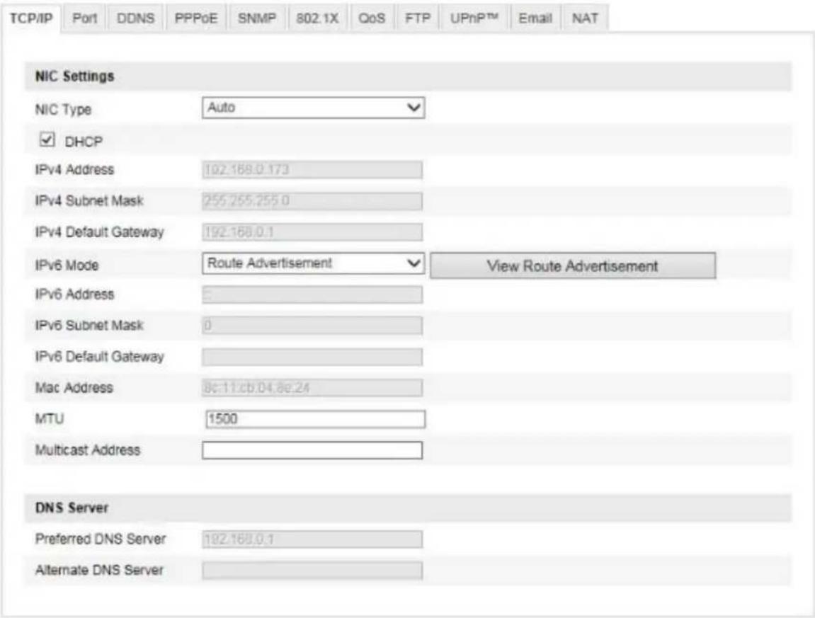
To be able to operate the Speed Dome via a network, the TCP/IP settings must be configured correctly.
NIC Settings
NIC Type
Select the setting for your network adapter.
You can choose from the following values: 10M Half-dup; 10M Full-dup; 100M Half-dup;
100M Full-dup; 10M/100M/1000M Auto.
DHCP
If a DHCP server is available, click 'DHCP' to apply an IP address and other network settings automatically.
The data is transferred automatically from the server and cannot be changed manually.
If no DHCP server is available, please enter the following data manually.
IPv4 Address
Setting of the IP address for the Speed Dome.
IPv4 Subnet Mask
Manual setting of the subnet mask for the Speed Dome.
IPv4 Default Gateway
Setting of the default router for the Speed Dome.
IPv6 Mode
Manual: Manual configuration of IPv6 data.
DHCP: The IPv6 connection data is provided by the DHCP server.
Route Advertisement: The IPv6 connection data is provided by the DHCP server (router) in connection with the ISP (Internet Service Provider).
IPv6 Address
Display of the IPv6 address. The address can be configured in the IPv6 'manual' mode.
IPv6 Subnet Mask
Display of the IPv6 subnet mask.
IPv6 Default Gateway
Display of the IPv6 default gateway (default router).
MAC Address
The IPv4 hardware address of the camera is displayed here. This cannot be changed.
MTU
Setting of the transmission unit. Select a value between 500 and 9676. 1500 is set by default.
DNS Server
Preferred DNS Server
DNS server settings are required for some applications (for example, sending emails). Enter the address of the preferred DNS server here.
Alternative DNS Server
If the preferred DNS server cannot be reached, this alternative DNS server is used. Please store the address of the alternative DNS server here.

Apply the settings by clicking 'Save'.
10.3.2.2 Port

If you wish to enable external access to the Speed Dome, the following ports must be configured.
HTTP Port
The standard port for HTTP transmission is 80. This port can alternatively be assigned a value in the range of 1024\~65535. If several Speed Domes are connected in the same subnetwork, each camera should be given a unique HTTP port of its own.
RTSP Port
The standard port for RTSP transmission is 554. This port can alternatively be assigned a value in the range of 1024\~65535. If several Speed Domes are connected in the same subnetwork, each camera should be given a unique RTSP port of its own.
HTTPS Port
The standard port for HTTPS transmission is 443.
Server Port (control port)
The standard port for SDK transmission is 8000. Communication port for internal data. This port can alternatively be assigned a value in the range of 1025\~65535. If several IP cameras are located in the same subnetwork, each camera should have its own unique server port.
| Apply the settings by clicking 'Save'. |
10.3.2.3 DDNS
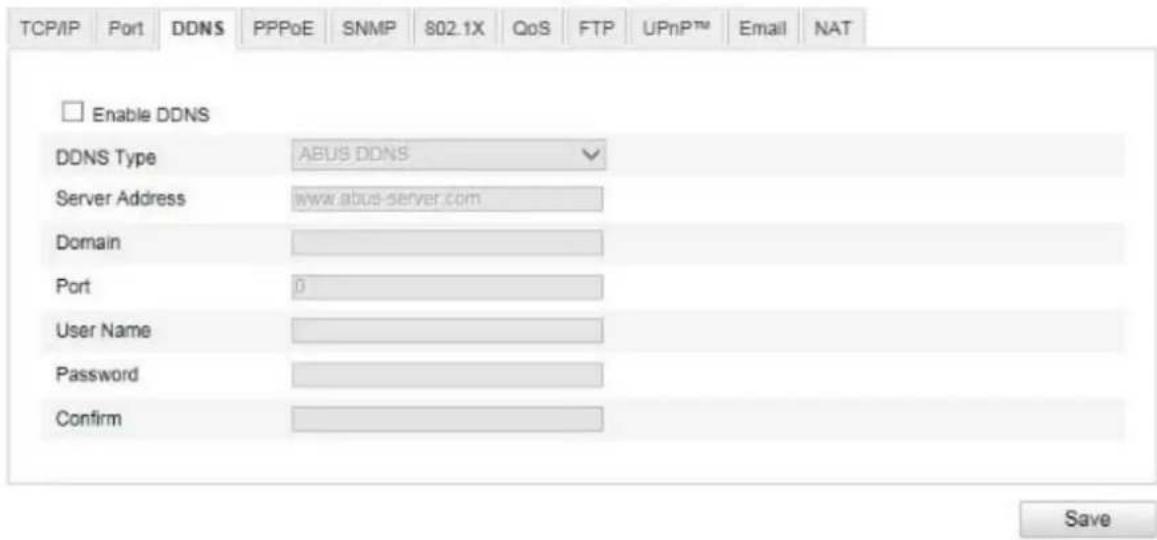
DDNS
DynDNS or DDNS (dynamic domain name system entry) is a system that can update domain name entries in real time. The network camera is equipped with an integrated DynDNS client that updates the IP address independently via a DynDNS provider. If the network camera is located behind a router, we recommend using the DynDNS function of the router.
The following diagram offers an overview of accessing and updating the IP address using DynDNS.
![graph TD A["① 192.168.0.3"] --> B["Network"] B --> C["② 195.184.21.78"] B --> D["③ DynDNS access data"] D --> E["Internet"] E --> F["DynDNS.org Name Server"] F --> G["④ 195.184.21.78 → name.dyndns.org"]](/content/2026/06/1271100/images/996a246916324a13ead85a1bfcb282e9f200eaffddd5ebcd89ce442980db7f02.jpg)
Enable DDNS
Enable or disable the DDNS function.
DDNS Type
Select the DDNS type. You can choose between 'DynDNS' and 'ABUS DDNS'.
Server Address
Select a DDNS service provider. You must have registered access to this DDNS service provider (e.g. www.dyndns.org).
If you select 'ABUS DDNS' as the DDNS type, the server address is stored automatically.
Domain
Enter the registered domain name (host service) here (e.g. myIPcamera.dyndns.org).
Port
Store the port for port forwarding here.
User name
User ID of your DDNS account.
Password
Password of your DDNS account.
Confirm
You must confirm your password here.
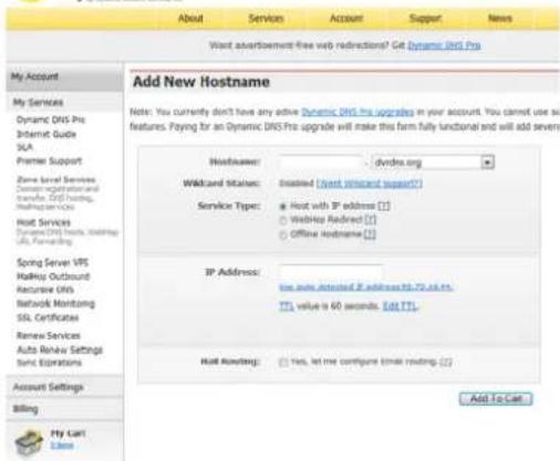
Setting up a DDNS account
Set up a new account under DynDNS.org:

Store your account information:
DynDNS.com

Note down your user data and enter this into the configuration of the network camera.
Accessing the network camera via DDNS
If the network camera is located behind a router, access via DynDNS must be configured in the router. On the ABUS Security-Center homepage www.abus-sc.com, you can find a description of the DynDNS router configuration for common router models.
The following diagram offers an overview of accessing a network camera behind a router via DynDNS.org.
![graph TD A["IP Device"] -->|⑤ 192.168.0.1| B["Server"] B --> C["Internet"] C --> D["Laptop"] D -->|① http://name.dyndns.org:1026| E["DynDNS.org Name Server"] E -->|③ 195.184.21.78:1026| C C -->|④ 195.184.21.78:1026| B style A fill:#f9f,stroke:#333 style B fill:#ccf,stroke:#333 style C fill:#cfc,stro…](/content/2026/06/1271100/images/9ef625c95c17fe3f098c3ed1689a67e4979145634e9d392694ebd871c1cf6199.jpg)

Port forwarding of all relevant ports (at least RTSP + HTTP) must be set up in the router in order to use DynDNS access via the router.

Apply the settings by clicking 'Save'. If the network configuration is changed, the camera must be rebooted (System/Maintenance/Reboot).
ABUS DDNS
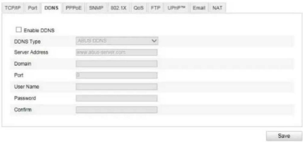
- To be able to use the ABUS DDNS function, you first need to set up an account at www.abus-server.com. Please read the FAQs on this topic on the website.
- Select the 'Enable DDNS' checkbox and select 'ABUS DDNS' as the DDNS type.
- Apply the data with 'Save'. The IP address of your Internet connection is now updated every minute on the server.
10.3.2.4 PPPoE
Enable PPPoE: Check this box to enable this function
Dynamic IP: The IP address is automatically determined
User name: User name of the service provider
Password: Password for access
Confirm: Password confirmation
10.3.2.5 SNMP
SNMP v1/2
Enable SNMPv1: Enabling of SNMPv1
Enable SNMPv2: Enabling of SNMPv2
Write SNMP Community: SNMP Community string for writing
Read SNMP Community: SNMP Community string for reading
Trap Address: IP address of the TRAP server
Trap Port: Port of the TRAP server
Trap Community: TRAP Community string

SNMP v3
Enable SNMPv3: Enabling of SNMPv3
Read UserName: Allocate user name
Security Level: Auth, priv: No authentication, no encryption Auth, no priv: Authentication, no encryption no auth, no priv: No authentication, encryption
Authent. algorithm: Select authentication algorithm: MD5, SDA
Authentication Password: Password assignment
Private-key Algorithm: Select encryption algorithm: DES, AES
Private-key password: Password assignment
Write UserName: Allocate user name
Security Level: Auth, priv: No authentication, no encryption
Auth, no priv: Authentication, no encryption
no auth, no priv: No authentication, encryption
Auth. algorithm: Select authentication algorithm: MD5, SDA
Authentication Password: Password assignment
Private-key Algorithm: Select encryption algorithm: DES, AES
Private-key password: Password assignment
Other SNMP settings
SNMP Port: Network port for the SNMP service
10.3.2.6 802.1X
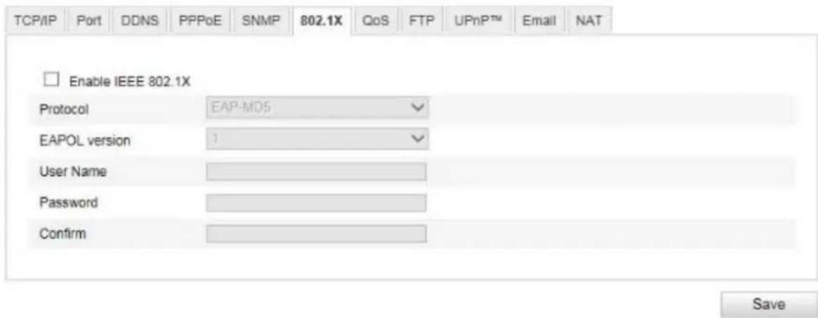
Enable IEEE 802.1X: Enable 802.1X authentication
Protocol: Protocol type EAP-MD5 (only)
EAPOL version: Extensible Authentication Protocol over LAN, choice between version 1 or 2
User name: Enter the user name
Password: Enter the password
Confirm: Password confirmation
10.3.2.7 QoS
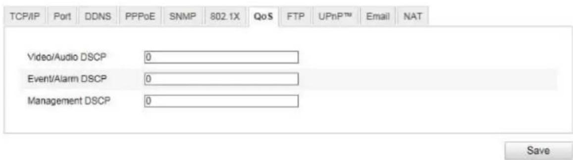
Video/Audio DSCP: (Differentiated Service Code Point) (0\~63): Priority for video/audio IP packages. The higher the value, the higher the priority.
Event/Alarm DSCP: (0\~63): Priority for event/alarm IP packages. The higher the value, the higher the priority.
Management DSCP: (0\~63): Priority for management IP packages. The higher the value, the higher the priority.
10.3.2.8 FTP
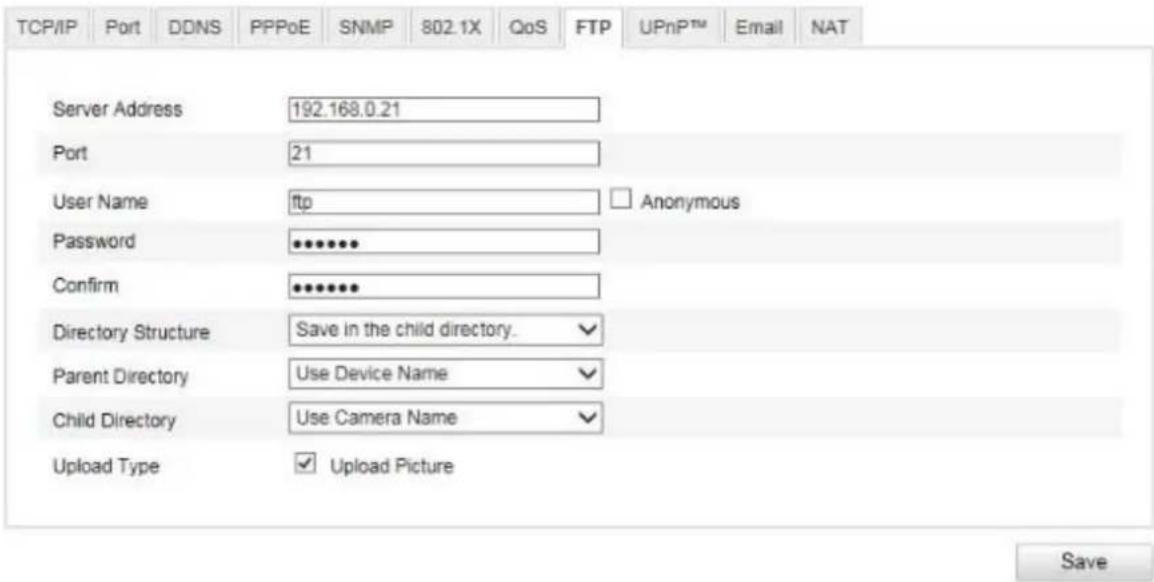
To upload recorded videos or images onto an FTP server, the following settings must be selected.
Server Address
Enter the IP address of the FTP server here.
Port
Enter the port number of the FTP server here. The standard port for FTP servers is 21.
User name
User name of the account that was configured in the FTP server.
Password
Password of the account that was configured in the FTP server.
Confirm
Re-enter the password here.
Directory Structure
Select the save location for the uploaded data here. You can select between
'Save in the root directory'; 'Save in the parent directory', 'Save in the child directory'.
Parent Directory
This menu item is available only if 'Save in the parent directory' or 'Save in the child directory' has been selected under Directory Structure. You can select the name for the parent directory here. The files are saved in a folder on the FTP server.
Choose between 'Use Device Name', 'Use Device Number' and 'Use Device IP address'.
Child Directory
Select the name for the child directory here. The folder is created in the parent directory. You can choose between 'Use Camera Name' or 'User Camera Number'.
Upload Type
Select 'Upload Picture' to upload pictures to the FTP server.

Apply the settings by clicking 'Save'.
10.3.2.9 UPnPTM
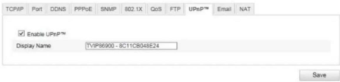
The UPnP (Universal Plug and Play) function makes it easy to control network devices in an IP network. This allows the network camera to be seen in the Windows network environment (e.g. as a network device).
Enable UPnPTM
For enabling or disabling the UPnP function.
Name
Display of the MAC address of the camera.

Apply the settings by clicking 'Save'.
10.3.2.10 Email

You can apply the settings for sending emails here.
Sender
Sender
Enter a name here to be displayed as the sender.
Sender's Address
Enter the email address of the sender here.
SMTP Server
Enter the IP address or host name of the SMTP server here (for example: smtp.googleapis.com).
SMTP Port
Enter the SMTP port here. This is configured as 25 by default.
Enable SSL
Select the SSL function if the SMTP server requires this.
Interval
Set the interval between sending emails with picture attachments here.
Attached Image
Enable this function if images are to be attached to the email in the event of an alarm.
Authentication
If the email server in use requires authentication, enable this function to be able to log onto the server with authentication.
User names and passwords can only be entered once this function has been enabled.
User name
Enter the user name of the email account here. This is the part before the @ symbol.
Password
Enter the password of the email account here.
Confirm
Confirm the password by entering it again.
Receiver
Receiver1/Receiver2
Enter the name of the receiver here.
Receiver1's Address / Receiver2's Address
Enter the email address of the person to be informed here.

Apply the settings by clicking 'Save'.
10.3.2.11 NAT
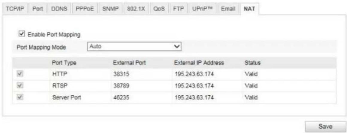
Enable Port Mapping
This enables Universal Plug and Play port forwarding for network services. If your router supports UPnP, then port forwarding for video streams is enabled automatically on the router for the network camera using this option.
Port Mapping Mode
Select here whether you wish to conduct port mapping automatically or manually.
You can choose between 'Auto' and 'Manual'.
Protocol Name:
HTTP
The standard port for HTTP transmission is 80. This port can alternatively be assigned a value in the range of 1025\~65535. If several IP cameras are located on the same subnetwork, each camera should have its own unique HTTP port.
RTSP
The standard port for RTSP transmission is 554. This port can alternatively be assigned a value in the range of 1025\~65535. If several IP cameras are located on the same subnetwork, each camera should have its own unique RTSP port.
Server Port (control port)
The standard port for SDK transmission is 8000. Communication port for internal data. This port can alternatively be assigned a value in the range of 1025\~65535. If several IP cameras are located in the same subnetwork, each camera should have its own unique server port.
External Port
You can only change ports manually here if the 'Port Mapping Mode' was set to manual.
Status
Displays whether the external port entered is valid or not valid.
10.3.3 Video/Audio
| Menu item Description Available in mode | ||
| Video | Settings for video output | Basic Configuration, Advanced Configuration |
| Audio (TVIP83900 only) | Settings for audio output Basic Configuration, | Advanced Configuration |
| ROI | 'Region of Interest' Basic Configuration, | Advanced Configuration |
10.3.3.1 Video

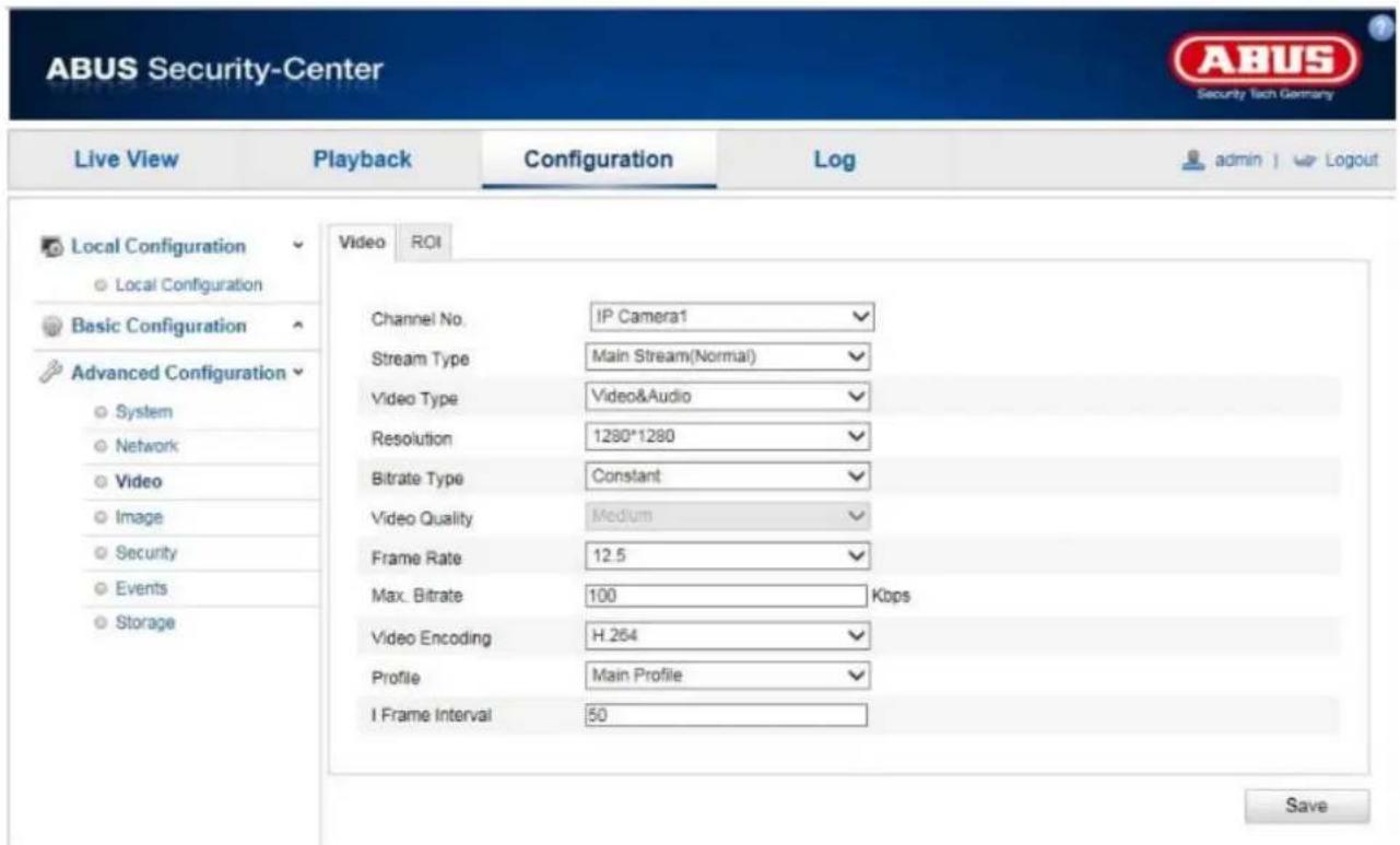
Channel Number
Select one of the five subchannels for setting the video parameters.
| Channel Number | Normal Mode | Real-time Mode |
| 1 | Fisheye | Fisheye |
| 2 | Panorama | PTZ |
| 3 | PTZ | PTZ |
| 4 | PTZ | PTZ |
| 5 | PTZ | PTZ |
 | In realtime mode either the fisheye view or 4 PTZ views can be displayed in browser or recording device. Display all 5 channels simultaneously is not possible. |
Stream Type
The camera has one stream per channel ('Main Stream (Normal)'). There are no other options available.
Video Type
Select either 'Video' or 'Video&Audio' for the stream type (TVIP83900 only).

The audio signal is only recorded if 'Video&Audio' is selected as the stream type.
Resolution
Set the resolution of the video data here.
TVIP83900
Resolutions available:
Real-time Mode: Fisheye (2048x2048, 1280x1280), PTZ (1024x768, 704x576, 640x480, 320x240)
Normal Mode: Fisheye (1536x1536), PTZ (800x600, 704x576, 640x480, 320x240), Panorama (1600x1200, 1280x720)
TVIP86900
Resolutions available:
Real-time Mode: Fisheye (3072x2048, 2048x2048, 1280x1280), PTZ (1024x768, 704x576, 640x480, 320x240)
Normal Mode: Fisheye (1280x1280), PTZ (1024x768, 704x576, 640x480, 320x240), Panorama (2048x1536, 1920x1080)
Bitrate Type
Specifies the bitrate of the video stream. The video quality can be higher or lower depending on the intensity of movement. You can select between a constant and variable bitrate.
Video Quality
This menu item is only available if you have selected a variable bitrate. Set the video quality for video data here. The video quality can differ depending on the intensity of movement. You can select from six different video qualities: 'Lowest', 'Lower', 'Low', 'Medium', 'Higher' or 'Highest'.
Frame Rate
Specifies the frame rate in frames per second.
Max. Bitrate
The bitrate of the video stream is set to a certain value. Set a maximum bitrate of between 32 and 16384 Kbps. A higher value means better video quality; however, this requires more bandwidth.
Video Encoding
Select a standard for video encoding. You can choose between H.264 and MJPEG (MJPEG can only be selected for PTZ channels. The fisheye channel and the panorama channel can only be used with H.264.).
Profile
Select a profile here. You can choose between 'Basic Profile', 'Main Profile' and 'High Profile'.
I Frame Interval
Set the I frame interval here. The value must lie between 1 and 400.
(For example: I frame interval = 50 -> one full screen every 2 seconds with the setting 25 frames per second.)

Apply the settings by clicking 'Save'.
10.3.3.2 Audio (only TVIP83900)

Select the encoding for audio transmission here.
You can choose between 'G.711ulaw', 'G.711alaw' and 'G.726'.
Audio Input
MicIn: The settings for the audio input on the back of the camera are customised to a microphone (unamplified source).
Lineln: The settings for the audio input on the back of the camera are customised to a line signal (active amplified source).
Volume
Adjust the volume of the input signal.
Noise Filter
Enable or disable the noise filter for background noise.

Apply the settings by clicking 'Save'.
10.3.3.3 ROI 'Region of Interest'
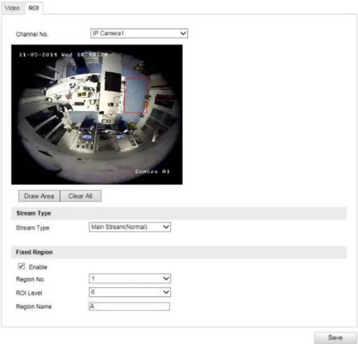
The 'Region of Interest (ROI)' function defines areas in the video image which are transmitted at a higher bitrate than the surrounding areas.
Channel Number: selection of the channel number for adding ROIs.
Draw Area: Depiction of up to four ROI areas per channel (the region number must be changed below for a new area).
Clear All: Delete all ROI areas in the video image.
Stream Type
Stream Type: ROI can only be used in the Normal Stream (Main Stream).
Fixed Region
Enable: Tick the selection box to enable all areas.
Region No (1–4): Select the four areas (four areas for each channel).
ROI Level (1–6): When using the value '6' the selected areas will be compromised the least (and therefore the highest possible quality will be achieved).
Region Name: Assign a name to the region.
10.3.4 Image
Display Settings OSD Settings Privacy Mask

^ Image Adjustment
Brightness
Contrast
Saturation
Hue
Sharpness
Exposure Settings
Day/Night Switch
Backlight Settings
▼ White Balance
Image Enhancement
- Video Adjustment
| Menu item Description | Available in mode | |
| Display Settings | Displaying parameter settings | Basic Configuration, Advanced Configuration |
| OSD Settings | Setting the date and time format Advanced | Configuration |
| Privacy Masking | Adding privacy masking Advanced | Configuration |
10.3.4.1 Display settings
Display Settings OSD Settings Privacy Mask


√ Exposure Settings
Day/Night Switch
Backlight Settings
▼ White Balance
Image Enhancement
- Video Adjustment
You can use this menu item to set the picture quality of the Speed Dome, for example brightness, sharpness, contrast. Click on 'Default' to restore the default values.

Please note:
The display setting parameters can vary depending on the model.
Image Adjustment
Brightness
Image brightness settings. A value between 0 and 100 can be set.
Contrast
Image contrast settings. A value between 0 and 100 can be set.
Saturation
Image saturation settings. A value between 0 and 100 can be set.
Hue
Setting the hue. A value between 0 and 100 can be set.
Sharpness
Image sharpness settings. A higher sharpness value can increase image noise.
A value between 0 and 100 can be set.
Exposure Settings
Exposure Mode
Automatic or manual setting of exposure parameters.
Exposure Time
Setting the maximum exposure time. This setting is dependent on iris mode.
Gain
Setting the gain value for the video image.
Day/Night Switching
Day/Night Switch
Day/Night Switch provides options for 'Auto', 'Day' and 'Night'.
Auto
Depending on the light conditions, the camera switches between day and night mode automatically. The sensitivity can be set between 0 and 7.
Day
In this mode, the camera only outputs colour pictures.

Please note:
Only use this mode if the light conditions remain constant.
Night
In this mode, the camera only outputs black/white pictures.

Please note:
Only use this mode if the light conditions are poor.
Schedule
Sensitivity
Setting for the switching threshold for automatic day/night switching (0–7).
A lower value means that there is a lower lighting level for switching to night mode.
Delay Time
Setting a delay time between recognising that a switching is required and carrying out the process.
Smart IR
This function can reduce the cross-fade of the video image, in the event that light is reflected from nearby objects.
Backlight Settings
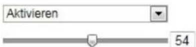
WDR
With the aid of the WDR function, the camera can return clear pictures even in disadvantageous backlight conditions. If there are both very bright and very dark areas in the picture area, the brightness level of the overall picture is balanced to provide a clear, detailed image.
Click on the checkbox to enable or disable the WDR function.
Set the Wide Dynamic Level higher to enhance the WDR function.
WDR
Wide Dynamic Level
White Balance
Here you select the lighting conditions in which the camera is installed.
You can choose from the following options: 'MWB', 'AWB1', 'WB Locked', 'Florescent Lamp', 'Incandescent Lamp', 'Warm Light Lamp', 'Natural Light'.
MWB
You can adjust the white balance with the following values manually.

The white balance is performed once and saved.
Other
Use additional white balance options to adjust the function to the light levels.
Florescent Lamp
Adjusts the white balance to florescent lamp lighting conditions.
Image Enhancement
Digital Noise Reduction
You can enable (Normal Mode) or disable the noise reduction.
Noise Reduction Level / 2D/3D DNR
Set the level for noise reduction here.
Grey Scale
This function limits the range of the grey scale representation. This can be beneficial in the case of very light image content.
Video Settings
Video Standard
Select the video standard corresponding to the available power frequency.
10.3.4.2 OSD Settings

You can use this menu item to select which date and time format are displayed in the live picture.
Display Name
Activate this checkbox if you wish to display the camera name.
Display Date
Activate this checkbox if you wish to display the date in the camera image.
Display Week
Activate this checkbox if you wish to display the day of the week.
Camera Name
Enter the camera name that is to be displayed in the image here.
Time Format
Choose here whether you would like to display the time in 24-hour or 12-hour format.
Date Format
Select the format for the date display here.
(D = day; M = month, Y = year)
Display Mode
Here you can select the display mode for the elements displayed.
You have the following options: 'Transparent & Flashing', 'Transparent & Not Flashing', 'Not Transparent & Flashing', 'Not Transparent & Not Flashing'.

Apply the settings by clicking 'Save'.
10.3.4.3 Privacy Mask
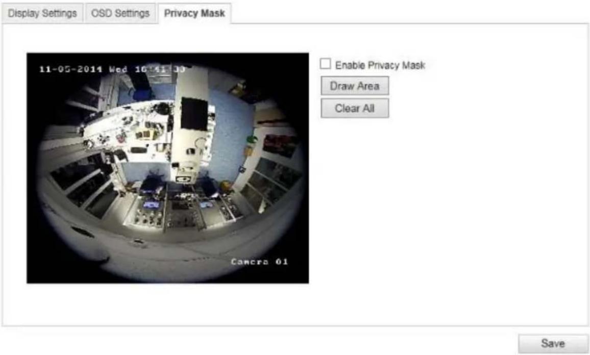
You can use privacy masks to hide certain areas in the live view to prevent these areas from being recorded and viewed in the live view. A maximum of four rectangular privacy masks can be set up in the video image.
To set up a privacy mask, proceed as follows. Select the checkbox
'Enable Privacy Mask'. To add a privacy mask, click 'Draw Area'. You can now select an area on the camera image using your mouse. You can then select three additional areas. By clicking on 'Clear All', you can delete all configured privacy masks.

Apply the settings by clicking 'Save'.
10.3.5 Security
| Menu item Description Available in mode | ||
| User | User administration | Basic Configuration, Advanced Configuration |
| RTSP Authentication | Setting the date and time format Advanced | Configuration |
| IP Address Filter | Filtering IP addresses to gain access for controlling the camera | Advanced Configuration |
10.3.5.1 User
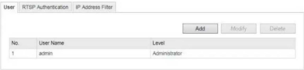
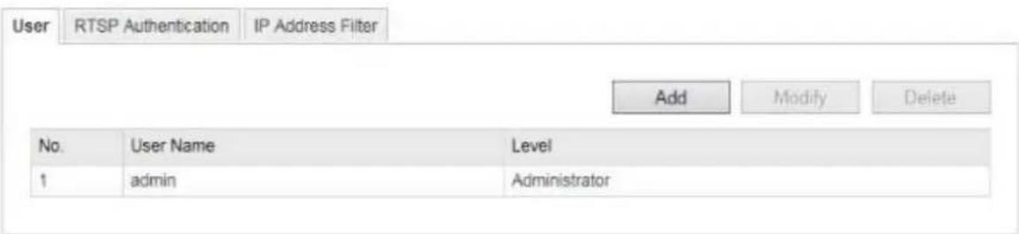
With this menu item, you can add, edit or delete users.
To add or modify a user, click 'Add' or 'Modify'.
A new window with the data and authorisations appears.
User name
Here you assign the user name that needs to be entered for access to the camera.
Level
Select an individual user type for the user ID.
You can choose between two predefined levels: 'Operator' or 'User'.
As an operator, the following remote functions are available to you: live view, PTZ control, manual recording, playback, two-way audio, search/query operating status.
As a user, the following remote functions are available to you: playback, search/query operating status.
To add further functions, select the corresponding checkbox.
Password
Here you assign the password that the corresponding user must enter to access the camera.
Confirm
Confirm the password by entering it again.

Apply the settings by clicking 'OK'. Click 'Cancel' to discard the data.
10.3.5.2 RTSP Authentication
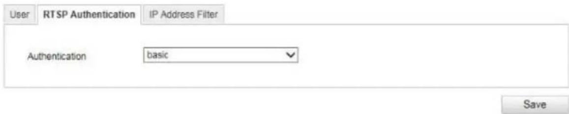
You can secure the video stream of the live view with this function.
Select 'Disable' to deactivate this function. To activate this function, select 'Basic'.

Apply the settings by clicking 'Save'.
10.3.5.3 IP Address Filter
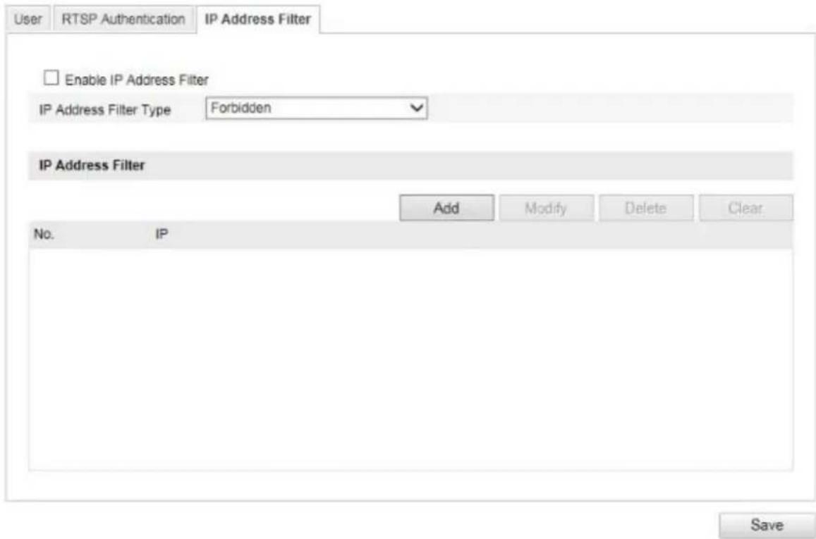
Enable IP Address Filter
Ticking the selection box enables the filter function.
IP Address Filter Type
Allowed: The IP addresses detailed further below can be used to access the camera.
Forbidden: The IP addresses detailed further below are blocked. An IP is entered in the format xxx.xxx.xxx.xxx.
10.3.6 Basic event
| Menu item Description Available in mode | ||
| Motion Detection | Settings for motion detection Advanced | Configuration |
| Video Tampering | Settings for video tampering Advanced | Configuration |
| Alarm Input | Setting for the alarm input Advanced | Configuration |
| Alarm Output | Setting for the alarm output Advanced | Configuration |
10.3.6.1 Motion detection

Area Settings
Activate motion detection by clicking the 'Enable Motion Detection' checkbox.
Clicking 'Enable Dynamic Analysis for Motion' means that movements are recorded in the preview image and the live view (dynamic recording according to motion).
To select an area, click on the 'Draw Area' button. The entire area is selected by default. To discard this selection, click on 'Clear All'.
Drag the mouse pointer over the desired area. Set the sensitivity using the regulation control bar. To apply the setting for the area, click on 'Stop Drawing'.
Right: low sensitivity level.
Left: high sensitivity level.
Arming Schedule
To save a schedule for motion-controlled recording, click on 'Edit'.
A new window appears. Specify here on which days of the week and at which times motion-controlled recording should take place.
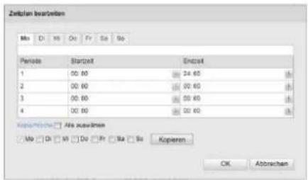
Now select a day of the week for motion-controlled recording. To store particular time periods, enter a start and end time. To set up all-day motion detection, select 00:00 as the start time and 24:00 as the end time.
To apply motion detection for all days of the week, click the 'Select All' checkbox. To copy motion detection to other days of the week, select the day of the week and click on 'Copy'.
To apply the changes, click 'OK' and to discard them click 'Cancel'.
Apply the settings made by clicking 'Save'.
Linkage Method
Here you can set the action to be performed following motion detection.
Normal Linkage
Send email: You receive an email as notification; check the checkbox to activate this.
Upload to FTP: Check this checkbox in order for the motion-controlled recording to be uploaded to an FTP server.
Trigger Channel: Enable this in order to record motion detections onto an SD card.
Other Linkage
You can choose to switch on the alarm output when motion is detected.
To switch on alarm output 1, select 'A->1'.

Apply the settings by clicking 'Save'.
10.3.6.2 Video tampering

With this menu item you can configure the Speed Dome so that video tampering is triggered as soon as the lens is covered.
Area Settings
Activate video tampering by clicking the 'Enable Video Tampering' checkbox.
To select an area, click on the 'Draw Area' button. The entire area is selected by default. To discard this selection, click on 'Clear All'.
Drag the mouse pointer over the desired area. Set the sensitivity using the regulation control bar. To apply the setting for the area, click on 'Stop Drawing'.
Right: low sensitivity level.
Left: high sensitivity level.
Arming Schedule
To save a schedule for the video tampering, click on 'Edit'.
A new window appears. Specify here on which days of the week and at which times the video tampering should be enabled.
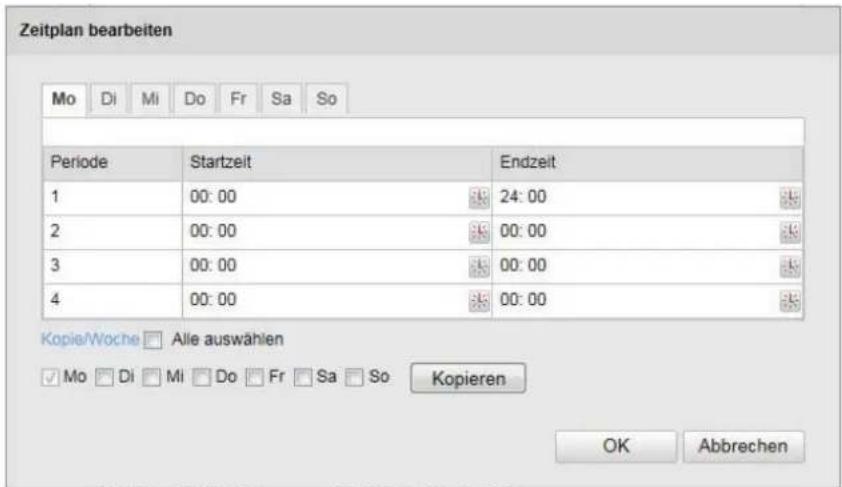
Now select a day of the week for the video tampering. To store particular time periods, enter a start and end time. To set up all-day video tampering, select 00:00 as the start time and 24:00 as the end time.
To activate video tampering for all days of the week, click the 'Select All' checkbox. To copy the video tampering to other days of the week, select the day of the week and click 'Copy'.
To apply the changes, click 'OK' and to discard them click 'Cancel'.
Linkage Method
Here you can set the action to be performed in case of video tampering.
Normal Linkage
Send email: You receive an email as notification; check the checkbox to activate this.
Other Linkage
You can switch on the alarm output when tampering is detected. To switch on alarm output 1, select 'A->1'.

Apply the settings by clicking 'Save'.
10.3.6.3 Alarm input (TVIP83900 only)

You can configure the alarm inputs of the Speed Dome with this menu item.
Alarm Input No.
Here you can select the alarm input that you wish to configure.
Alarm Name
You can specify a device name for the alarm input here. Please do not use the alarm input number or any special characters.
Alarm Type
Select the alarm type here. You can choose between 'NO' (normally open) or 'NC' (normally closed).
Arming Schedule
To save a schedule for an alarm input, click on 'Edit'.
A new window appears. Specify here on which days of the week and at which times the alarm input should be enabled.
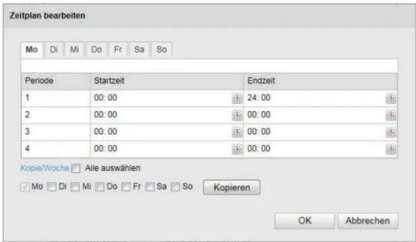
Now select a day of the week for the alarm input. To store particular time periods, enter a start and end time. To activate the alarm input all day, select 00:00 as the start time and 24:00 as the end time.
To apply the settings for all days of the week, click the 'Select All' checkbox. To copy the settings to other days of the week, select the day of the week and click on 'Copy'.
To apply the changes, click 'OK' and to discard them click 'Cancel'.
Linkage Method
Here you can set the action to be performed following motion detection.
Normal Linkage
Send email: You receive an email as notification; check the checkbox to activate this.
Upload to FTP: Check this checkbox in order for the alarm input to be uploaded to an FTP server.
Other Linkage
You can set the alarm output to switch when an alarm is detected. To switch on alarm output 1, select 'A->1'.

Apply the settings by clicking 'Save'.
10.3.6.4 Alarm output (TVIP83900 only)
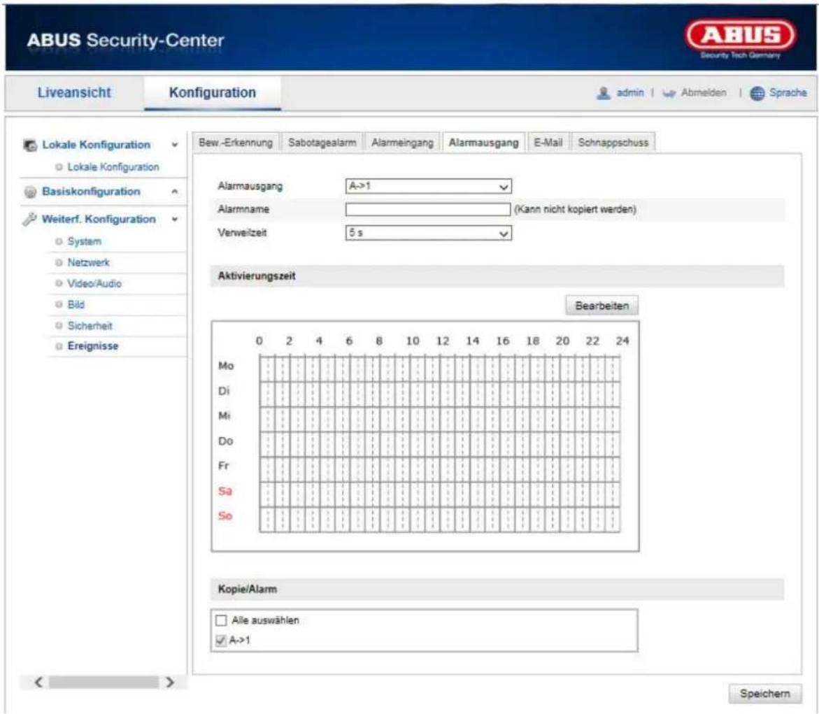
You can configure the two alarm outputs here.
Alarm Output No.
Here, select the alarm output that you wish to configure.
Alarm Name
You can specify a name for the relevant alarm output here. Please do not use the alarm output number or any special characters.
Arming Schedule
To save a schedule for an alarm output, click on 'Edit'.
A new window appears. Specify here on which days of the week and at which times the alarm output should be enabled.
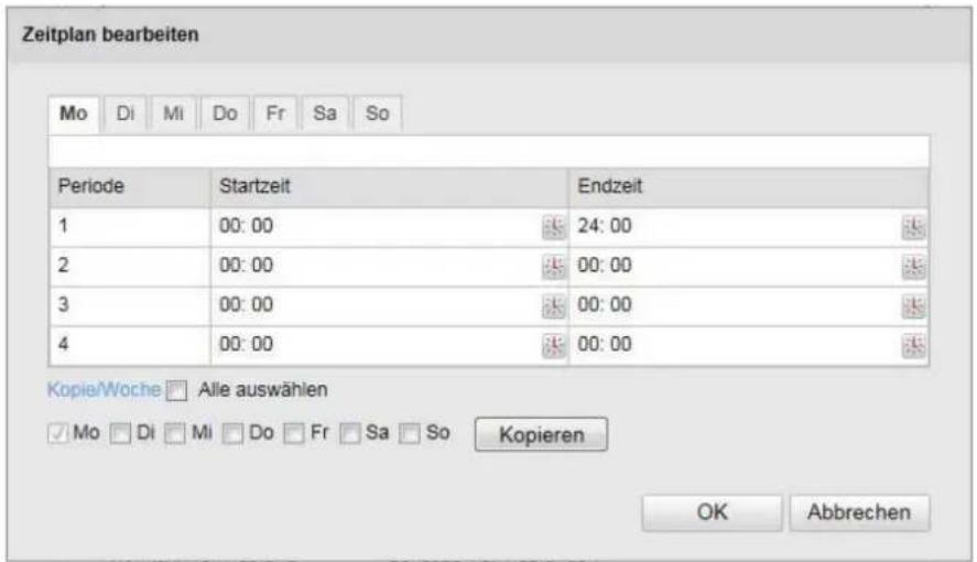
Now select a day of the week for the alarm output. To store particular time periods, enter a start and end time. To activate the alarm input all day, select 00:00 as the start time and 24:00 as the end time.
To apply the settings for all days of the week, click the 'Select All' checkbox. To copy the settings to other days of the week, select the day of the week and click on 'Copy'.
To apply the changes, click 'OK' and to discard them click 'Cancel'.
10.3.8 Storage
10.3.8.1 Record schedule

Here, you can set the configuration for time and event-triggered recordings in order to be able to save them to an SD card.
Pre-record
Set the duration for recording of the image data before a basic event here.
Post-record
Set the duration for recording of the image data after a basic event here.
Overwrite
Set here whether the recording should be automatically overwritten if the storage capacity is full.
Enable Record Schedule
Enable the schedule to store the desired schedule.
To store the schedule, click 'Edit'. A new window opens.
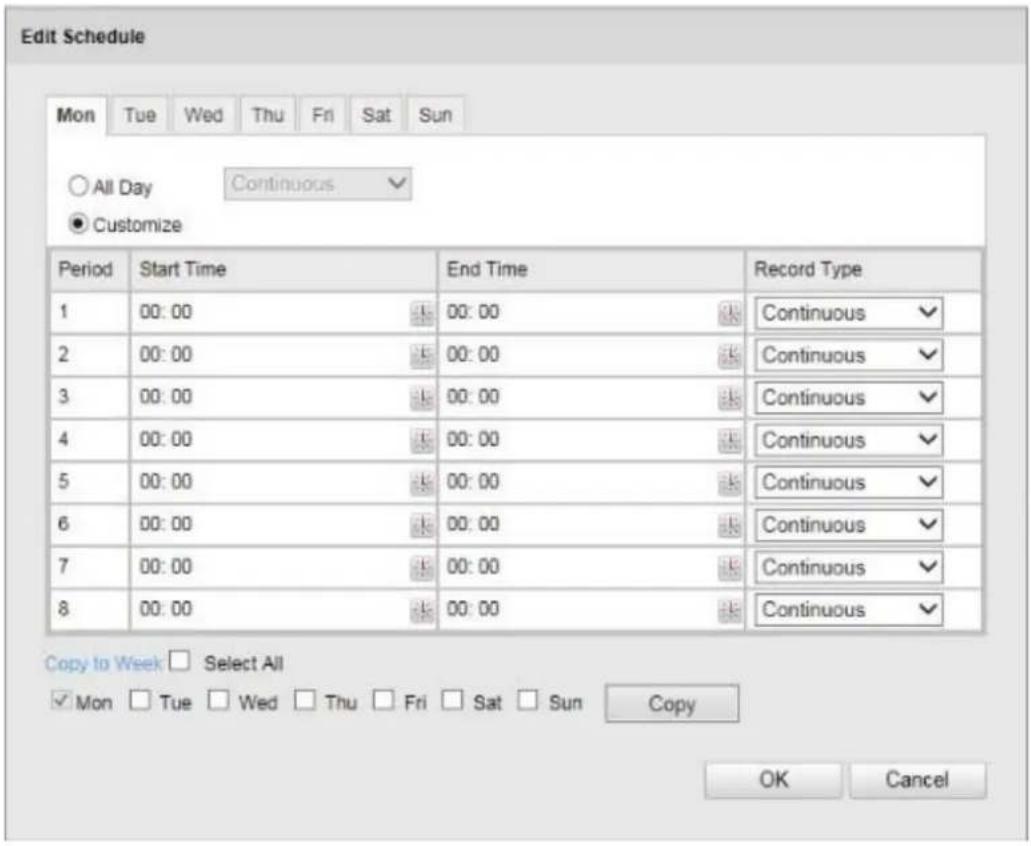
Now select a day of the week for the recording to take place. To store particular time periods, enter a start and end time. To activate the alarm input all day, select 00:00 as the start time and 24:00 as the end time. To apply the settings for all days of the week, click the 'Select All' checkbox. To copy the settings to other days of the week, select the day of the week and click on 'Copy'.
Under Record Type, select the recording mode for the desired schedule. You can
choose between the following record types:
Normal: permanent recording.
Motion Detection: motion-triggered recording.
Motion/Alarm: recording triggered by motion or by alarm input. Camera begins recording either following motion detection or an alarm input.
Motion & Alarm: recording triggered by motion and by alarm input. Camera only starts recording if motion and alarm input are triggered simultaneously.

Please note that the alarm input is only available in certain models.
To apply the changes, click 'OK' and to discard them click 'Cancel'.

Please note:
The MicroSD record function will record the 1st channel only (Fisheye view). This data can be playback over camera's internal playback interface
10.3.8.2 Storage management
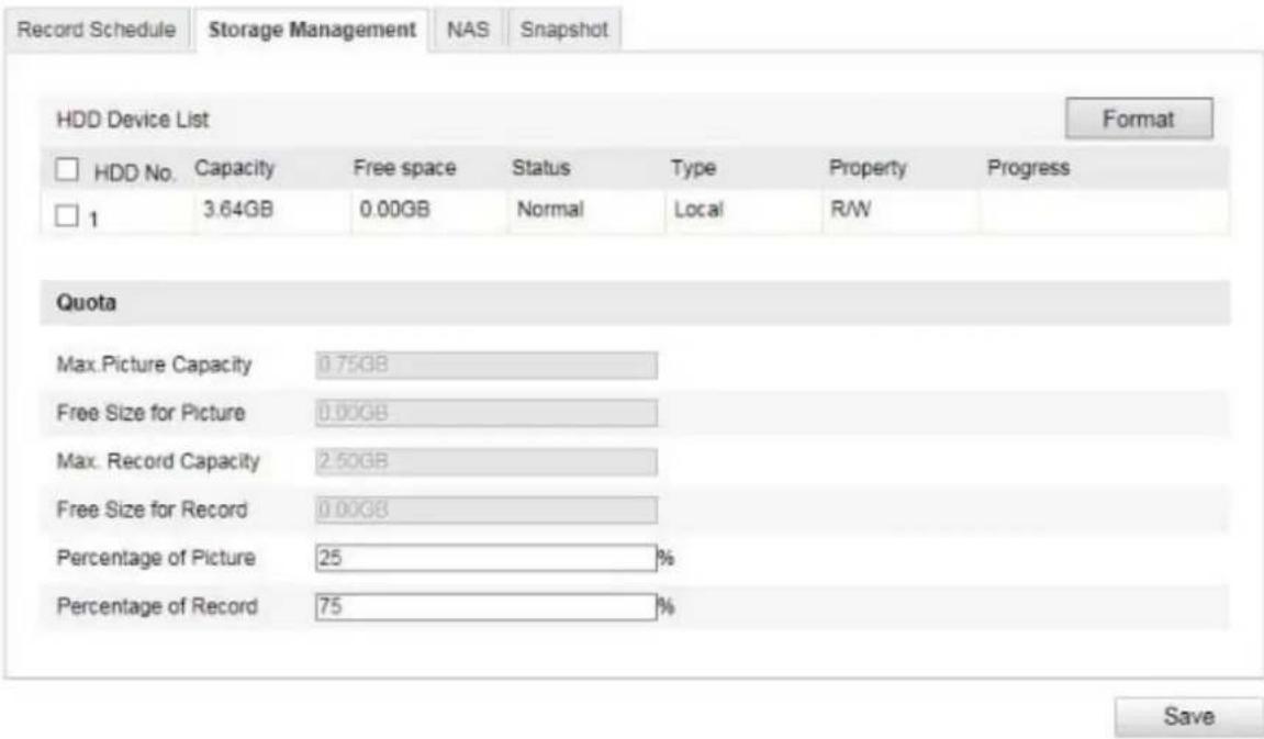
Here you can format the inserted micro SD card and display its properties.
Please format the SD card before using it for the first time.
10.3.8.3 NAS
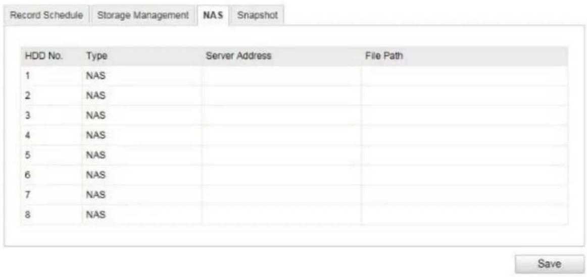
This menu can be used to set the NAS storage locations; these are then available in the camera as a drive (HDD) for storage (channel 1, "fisheye view").
Server Address IP address of the NAS drive
File Path: path on the NAS drive
 | Please note:The NAS record function will record the 1st channel only (Fisheye view). This data can be playback over camera's internal playback interface |
10.3.8.4 Snapshot
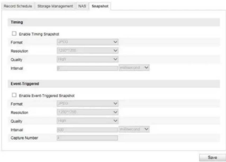
You can configure time and event-triggered snapshots here in order to set them to be uploaded to an FTP server.
Timing
Enable Timing Snapshot
Enable this function to save pictures at certain intervals.
Format
The format for the pictures is preconfigured as JPEG.
Resolution
Set the resolution of the picture here.
Quality
Select the quality for the saved pictures here.
Interval
Set the interval to occur between the saving of two pictures here.
Event-Triggered
Enable Event-Triggered Snapshot
Enable this function to save event-triggered pictures.
Format
The format for the pictures is preconfigured as JPEG.
Resolution
Set the resolution of the picture here.
Quality
Select the quality for the saved pictures here.
Interval
Set the interval to occur between the saving of two pictures here.
11. Maintenance and cleaning
11.1 Maintenance
Regularly check the technical safety of the product, e.g. check the housing for damage.
If it seems that it may no longer be possible to operate the device safely, stop using the product and secure it to prevent unintentional use.
It is likely that safe operation is no longer possible in the event that:
- the device shows signs of visible damage
• the device no longer works correctly.

Please note:
You do not need to perform any maintenance on the product. There are no components to service and nothing inside the product to check. Never open it.
11.2 Cleaning
Clean the product with a clean, dry cloth. The cloth can be dampened with lukewarm water if there is dirt that is hard to remove.

Do not allow any liquids to enter the device.
Do not use any chemical cleaning products as they could damage the surface of the housing and screen (discolouration).
12. Disposal

Important: EU Directive 2002/96/EC regulates the proper return, treatment and recycling of used electronic devices. This symbol means that in the interest of environmental protection, the device must be disposed of separately from household or industrial waste at the end of its service life in accordance with applicable local legal guidelines. Used devices can be disposed of at official recycling centres in your country. Obey local regulations when disposing of material. Further details on returns (also for non-European countries) can be obtained from your local authority. Separate collection and recycling conserves natural resources and ensures that all the provisions for protecting health and the environment are observed when recycling the product.
- Technical data
| Model number TVIP83900 TVIP86900 | ||
| Image sensor | 1/3" progressive scan CMOS sensor | 1/3" progressive scan CMOS sensor |
| Camera type Day/night Day/night | ||
| Resolution | Real-time Mode: Fisheye (2048x2048, 1280x1280), PTZ (1024x768, 704x576, 640x480, 320x240) Normal Mode: Fisheye (1536x1536), PTZ (800x600, 704x576, 640x480, 320x240), Panorama (1600x1200, 1280x720) | Real-time Mode: Fisheye (3072x2048, 2048x2048, 1280x1280), PTZ (1024x768, 704x576, 640x480, 320x240) Normal Mode: Fisheye (1280x1280), PTZ (1024x768, 704x576, 640x480, 320x240), Panorama (2048x1536, 1920x1080) |
| Pixels (total) 2048x2048 3072x2048 | ||
| Pixels (effective) 2048x2048 3072x2048 | ||
| Day/night switching | Electromechanical IR-cut filter | Electromechanical IR-cut filter |
| Minimum illumination (colour) | 0.05 Lux 0.05 Lux | |
| Minimum illumination (IR) 0 Lux 0 Lux | ||
| Image compression | H.264, MJPEG | H.264, MJPEG |
| Frame rate | Max. 25 fps | Max. 25 fps |
| Number of parallel streams | 5 (normal mode) | 5 (normal mode) |
| Electronic shutter control | 1 ~ 1/10000 sec. | 1 ~ 1/10000 sec. |
| White balance | ATW, manual | ATW, manual |
| Backlight compensation | BLC | BLC, WDR |
| Noise reduction | 2D/3D DNR | 2D/3D DNR |
| Motion detection | Yes | Yes |
| Image overlay | Date, camera name, privacy mask | Date, camera name, privacy mask |
| Alarm input (NO/NC) | 1 | - |
| Alarm output | 1 | - |
| Danger detection | Email/FTP/alarm output | Email/FTP/alarm output |
| Supported browsers | Mozilla Firefox, Safari or Internet Explorer 6.x and higher | Mozilla Firefox, Safari or Internet Explorer 6.x and higher |
| Supported software/NVR | ABUS VMS, TVVR35011, TVVR450x1, TVVR600x1 | ABUS VMS, TVVR35011, TVVR450x1, TVVR600x1 |
| Network connector | RJ-45 Ethernet 10/100 Base-T | RJ-45 Ethernet 10/100 Base-T |
| Network protocols | IPv4/IPv6, HTTP, FTP, SMTP, UPnP, DNS, DDNS, NTP, RTSP, RTP,TCP, UDP, DHCP, PPPoE, 802.1X, QoS, SNMPv1, v2, v3 | IPv4/IPv6, HTTP, FTP, SMTP, UPnP, DNS, DDNS, NTP, RTSP, RTP,TCP, UDP, DHCP, PPPoE, 802.1X, QoS, SNMPv1, v2, v3 |
| Power over Ethernet | IEEE803.af | IEEE803.af |
| Power supply | 12 V DC | 12 V DC |
| Current consumption | Max. 1 A | Max. 1 A |
| Operating temperature | -10°C - 50°C | -20°C - 55°C |
| Dimensions (WxHxD) | 72 x 65 x 141 mm | 72 x 65 x 141 mm |
| Certifications | CE, RoHS, REACH | CE, RoHS, REACH |
14. GPL license information
Here we wish to inform you that the network surveillance cameras TVIP83900 and TVIP86900, amongst others, include open source software licensed exclusively under the GNU General Public License (GPL). To ensure that your use of the programs conforms with GPL, please refer to the GPL license conditions.
① Câble Ethernet Cat5
Mode normal : Fisheye (1536x1536), PTZ (800x600, 704x576, 640x480, 320x240), Panorama (1600x1200, 1280x720))
100M Full-dup ; 10M/100M/1000M Auto
DHCP
Activer Mapping Port
(J = jour, M = mois, A = an)
Mode affichage
① Cat5-ethernetkabel
Beschikbare resoluties:
Realtime-modus: fisheye (2048x2048, 1280x1280), PTZ (1024x768, 704x576, 640x480, 320x240)
Normale modus: fisheye (1536x1536), PTZ (800x600, 704x576, 640x480, 320x240), panorama (1600x1200, 1280x720))
Beschikbare opties in live-weergavemodus:
Real-time-modus: Fisheye-weergave, 4 PTZ weergaven
Normale modus: Fisheye-weergave, panoramaweergave, 1 x fisheye + 3 x PTZ, 1 x panorama + 3 x PTZ
TVIP86900
Beschikbare resoluties:
Realtime-modus: fisheye (3072x2048, 2048x2048, 1280x1280), PTZ (1024x768, 704x576, 640x480, 320x240)
Normale modus: fisheye (1280x1280), PTZ (1024x768, 704x576, 640x480, 320x240), panorama (2048x1536, 1920x1080)
Beschikbare opties in live-weergavemodus:
Real-time-modus: Fisheye-weergave, 4 PTZ weergaven
Normale modus: Fisheye-weergave, panoramaweergave, 1 x fisheye + 3 x PTZ, 1 x panorama + 3 x PTZ
| Kanaalnummer | Normale | modus | Real-time-modus |
| 1 | Fisheye | Fisheye | |
| 2 | Panorama | PTZ | |
| 3 | PTZ | PTZ | |
| 4 | PTZ | PTZ | |
| 5 | PTZ | PTZ |

In realtime mode either the fisheye view or 4 PTZ views can be displayed in browser or recording device. Display all 5 channels simultaneously is not possible.
Type bevestiging:
100M Full-dup; 10M/100M/1000M Auto
DHCP
Accountgegevens invullen:
DynDNS.com
Trap Community: TRAP Community string
SNMP v3
Beschikbare resoluties:
Realtime-modus: fisheye ( , 2048x2048, 1280x1280), PTZ (1024x768, 704x576, 640x480, 320x240)
Normale modus: fisheye (1536x1536), PTZ (800x600, 704x576, 640x480, 320x240), panorama (1600x1200, 1280x720))
TVIP86900
Beschikbare resoluties:
Realtime-modus: fisheye (3072x2048, 2048x2048, 1280x1280), PTZ (1024x768, 704x576, 640x480, 320x240)
Normale modus: fisheye (1280x1280), PTZ (1024x768, 704x576, 640x480, 320x240), panorama (2048x1536, 1920x1080)
Bitratetype
Timing-snapshot activeren
① Cat5 ethernetkabel
In realtime mode either the fisheye view or 4 PTZ views can be displayed in browser or recording device. Display all 5 channels simultaneously is not possible.
Monteringstype:
100M full-dup; 10M/100M/1000M auto
DHCP
Billedjustering
- Indstillinger for eksponering
Irismodus
Manual
Eksponeringstid
1/25
Forstærkning
100
- Skift mellem dag/nat
- Indstillinger for baggrundslys
Hvidbalance
Billedforbedring - Videojustering
Billedjustering
^ Indstillinger for eksponering
Irismodus

Eksponeringstid

Forstærkning

- Skift mellem dag/nat
- Indstillinger for baggrundslys
Hvidbalance
Billedforbedring - Videojustering
Instrukcja obsługi
Wersja 12/2014
CE
① Kabel Ethernet Cat5
① Кабель Ethernet
These operating instructions are published by ABUS Security-Center GmbH & Co.KG, Linker Kreuthweg 5, 86444 Affing, Germany. No reproduction (including translation) is permitted in whole or part e.g. photocopy, microfilming or storage in electronic data processing equipment, without the express written consent of the publisher.
The operating instructions reflect the current technical specifications at the time of print.
We reserve the right to change the technical or physical specifications.
© Copyright 12/2014 by ABUS Security-Center
- FRANÇAIS
- BEDIENUNGSANLEITUNG
- DHCP
- SNMP V3
- USER MANUAL
- INTRODUCTION
- DISCLAIMER
- EXPLANATION OF SYMBOLS
- IMPORTANT SAFETY INFORMATION
- THE FOLLOWING SAFETY INFORMATION AND HAZARD NOTES ARE NOT ONLY INTENDED TO PROTECT YOUR HEALTH, BUT ALSO TO PROTECT THE DEVICE FROM DAMAGE. PLEASE READ THE FOLLOWING POINTS CAREFULLY
- SAFETY INFORMATION
- OVERLOADING
- CLEANING
- WARNINGS
- UNPACKING THE DEVICE
- CONTENTS
- INTENDED USE
- SCOPE OF DELIVERY
- FEATURES AND FUNCTIONS
- DEVICE DESCRIPTION
- DESCRIPTION OF THE CONNECTIONS
- INITIAL START-UP
- CONNECTING THE NETWORK CAMERA DIRECTLY TO A PC/LAPTOP
- CONNECTING THE NETWORK CAMERA TO A ROUTER/SWITCH
- ACCESSING THE NETWORK CAMERA FOR THE FIRST TIME
- PASSWORD PROMPT
- USER FUNCTIONS
- 9.1 MENU BAR
- 9.2 LIVE IMAGE DISPLAY
- 9.3 AUDIO/VIDEO CONTROL
- 9.4 LIVE VIEW MODE
- 9.5 PTZ CONTROL
- 9.5.1 PRESET SETTINGS
- 9.6 PATROL SETTINGS
- CONFIGURATION
- 10.1 LOCAL CONFIGURATION
- LIVE VIEW PARAMETERS
- PROTOCOL
- LIVE VIEW PERFORMANCE
- RULES
- IMAGE FORMAT
- RECORDING FILE SETTINGS
- RECORDING FILE SIZE
- SAVE RECORD FILES TO
- SAVE DOWNLOADED FILES TO
- IMAGE SAVE SETTINGS
- SAVE SNAPSHOTS IN LIVE VIEW TO
- SAVE SNAPSHOTS DURING PLAYBACK TO
- SAVE CLIPS TO
- 10.2 BASIC CONFIGURATION
- 10.3 ADVANCED CONFIGURATION
- 10.3.1 SYSTEM
- 10.3.1.1 DEVICE INFORMATION
- BASIC INFORMATION
- DEVICE NAME
- MODEL
- SERIAL NUMBER
- FIRMWARE VERSION
- ENCODING VERSION
- NUMBER OF CHANNELS
- NUMBER OF HDDS/SDS
- NUMBER OF ALARM INPUT
- NUMBER OF ALARM OUTPUT
- 10.3.1.2 TIME SETTINGS
- TIME ZONE
- TIME SYNC
- NTP
- SERVER ADDRESS
- NTP PORT
- MANUAL TIME SYNC
- DEVICE TIME
- SET TIME
- REBOOT
- DEFAULT
- RESTORE
- IMPORT CONFIG. FILE
- CONFIG FILE
- STATUS
- EXPORT CONFIG. FILE
- REMOTE UPGRADE
- FIRMWARE
- 10.3.1.4 DAYLIGHT SAVING TIME
- DAYLIGHT SAVING TIME
- ENABLE DST
- START TIME
- END TIME
- 10.3.1.5 FISHEYE PARAMETERS
- REAL-TIME MODE
- TVIP83900
- TVIP86900
- MOUNT MODE
- 10.3.2 NETWORK
- NIC SETTINGS
- IPV4 ADDRESS
- IPV4 SUBNET MASK
- IPV4 DEFAULT GATEWAY
- IPV6 MODE
- IPV6 ADDRESS
- IPV6 SUBNET MASK
- IPV6 DEFAULT GATEWAY
- MAC ADDRESS
- MTU
- DNS SERVER
- PREFERRED DNS SERVER
- ALTERNATIVE DNS SERVER
- 10.3.2.2 PORT
- HTTP PORT
- RTSP PORT
- HTTPS PORT
- SERVER PORT (CONTROL PORT)
- 10.3.2.3 DDNS
- DDNS
- ENABLE DDNS
- DDNS TYPE
- DOMAIN
- PORT
- USER NAME
- PASSWORD
- CONFIRM
- SETTING UP A DDNS ACCOUNT
- DYNDNS.COM
- ACCESSING THE NETWORK CAMERA VIA DDNS
- ABUS DDNS
- 10.3.2.4 PPPOE
- 10.3.2.5 SNMP
- SNMP V1/2
- OTHER SNMP SETTINGS
- 10.3.2.6 802.1X
- 10.3.2.7 QOS
- 10.3.2.8 FTP
- DIRECTORY STRUCTURE
- PARENT DIRECTORY
- CHILD DIRECTORY
- UPLOAD TYPE
- 10.3.2.9 UPNPTM
- ENABLE UPNPTM
- NAME
- 10.3.2.10 EMAIL
- SENDER
- SENDER'S ADDRESS
- SMTP SERVER
- SMTP PORT
- ENABLE SSL
- INTERVAL
- ATTACHED IMAGE
- AUTHENTICATION
- RECEIVER
- RECEIVER1/RECEIVER2
- RECEIVER1'S ADDRESS / RECEIVER2'S ADDRESS
- 10.3.2.11 NAT
- ENABLE PORT MAPPING
- PORT MAPPING MODE
- PROTOCOL NAME
- HTTP
- RTSP
- EXTERNAL PORT
- 10.3.3 VIDEO/AUDIO
- 10.3.3.1 VIDEO
- CHANNEL NUMBER
- STREAM TYPE
- VIDEO TYPE
- RESOLUTION
- RESOLUTIONS AVAILABLE
- BITRATE TYPE
- VIDEO QUALITY
- FRAME RATE
- MAX. BITRATE
- VIDEO ENCODING
- PROFILE
- I FRAME INTERVAL
- 10.3.3.2 AUDIO (ONLY TVIP83900)
- AUDIO INPUT
- VOLUME
- NOISE FILTER
- 10.3.3.3 ROI 'REGION OF INTEREST
- FIXED REGION
- 10.3.4 IMAGE
- 10.3.4.1 DISPLAY SETTINGS
- PLEASE NOTE
- IMAGE ADJUSTMENT
- BRIGHTNESS
- CONTRAST
- SATURATION
- HUE
- SHARPNESS
- EXPOSURE SETTINGS
- EXPOSURE MODE
- EXPOSURE TIME
- GAIN
- DAY/NIGHT SWITCHING
- DAY/NIGHT SWITCH
- AUTO
- DAY
- NIGHT
- SCHEDULE
- SENSITIVITY
- DELAY TIME
- SMART IR
- BACKLIGHT SETTINGS
- WDR
- WHITE BALANCE
- MWB
- OTHER
- FLORESCENT LAMP
- IMAGE ENHANCEMENT
- DIGITAL NOISE REDUCTION
- NOISE REDUCTION LEVEL / 2D/3D DNR
- GREY SCALE
- VIDEO SETTINGS
- VIDEO STANDARD
- 10.3.4.2 OSD SETTINGS
- DISPLAY NAME
- DISPLAY DATE
- DISPLAY WEEK
- CAMERA NAME
- TIME FORMAT
- DATE FORMAT
- DISPLAY MODE
- 10.3.4.3 PRIVACY MASK
- 10.3.5 SECURITY
- 10.3.5.1 USER
- LEVEL
- 10.3.5.2 RTSP AUTHENTICATION
- 10.3.5.3 IP ADDRESS FILTER
- ENABLE IP ADDRESS FILTER
- IP ADDRESS FILTER TYPE
- 10.3.6 BASIC EVENT
- 10.3.6.1 MOTION DETECTION
- AREA SETTINGS
- ARMING SCHEDULE
- LINKAGE METHOD
- NORMAL LINKAGE
- OTHER LINKAGE
- 10.3.6.2 VIDEO TAMPERING
- 10.3.6.3 ALARM INPUT (TVIP83900 ONLY)
- ALARM INPUT NO
- ALARM NAME
- ALARM TYPE
- 10.3.6.4 ALARM OUTPUT (TVIP83900 ONLY)
- ALARM OUTPUT NO
- 10.3.8 STORAGE
- 10.3.8.1 RECORD SCHEDULE
- PRE-RECORD
- POST-RECORD
- OVERWRITE
- ENABLE RECORD SCHEDULE
- 10.3.8.2 STORAGE MANAGEMENT
- 10.3.8.3 NAS
- 10.3.8.4 SNAPSHOT
- TIMING
- ENABLE TIMING SNAPSHOT
- FORMAT
- QUALITY
- EVENT-TRIGGERED
- ENABLE EVENT-TRIGGERED SNAPSHOT
- MAINTENANCE AND CLEANING
- 11.1 MAINTENANCE
- 11.2 CLEANING
- DISPOSAL
- GPL LICENSE INFORMATION
- ACTIVER MAPPING PORT
- MODE AFFICHAGE
- TYPE BEVESTIGING
- ACCOUNTGEGEVENS INVULLEN
- BESCHIKBARE RESOLUTIES
- BITRATETYPE
- TIMING-SNAPSHOT ACTIVEREN
- MONTERINGSTYPE
- INSTRUKCJA OBSŁUGI
Brand : ABUS
Model : TVIP86900
Category : Surveillance Camera