
UB1103 - Heat gun MAKITA - Free user manual and instructions
Find the device manual for free UB1103 MAKITA in PDF.


| Product type | Heat gun |
| Brand | Makita |
| Model | UB1103 |
| Dimensions (L x W x H) | 250 x 80 x 200 mm |
| Weight | 0.5 kg |
| Power supply | Mains 230 V ~ 50 Hz |
| Power | 1600 W |
| Maximum temperature | 600 °C |
| Airflow rate | 300 L/min |
| Temperature adjustment | Stepless variable control |
| Main functions | Paint stripping, plastic welding, defrosting, heat shrink tubing |
| Included accessories | Flat nozzle, reflector nozzle |
| Protections | Thermal protection, double insulation |
| Power cable | 2 m |
| Maintenance | Clean the air intake grille regularly with compressed air |
| Repairability | Repairability index not communicated; spare parts available from Makita after-sales service |
Frequently Asked Questions - UB1103 MAKITA
User questions about UB1103 MAKITA
0 question about this device. Answer the ones you know or ask your own.
Ask a new question about this device
Download the instructions for your Heat gun in PDF format for free! Find your manual UB1103 - MAKITA and take your electronic device back in hand. On this page are published all the documents necessary for the use of your device. UB1103 by MAKITA.
USER MANUAL UB1103 MAKITA
GB Blower Instruction Manual
1

2
014256

3
4
014257014419

5

6
004757014258

7
8
014259
ENGLISH (Original instructions)
Explanation of general view
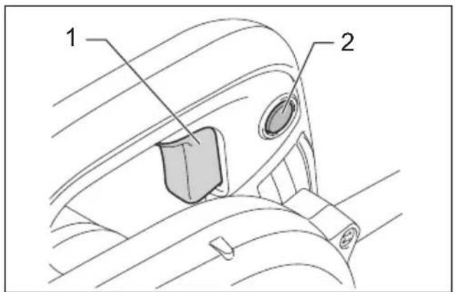
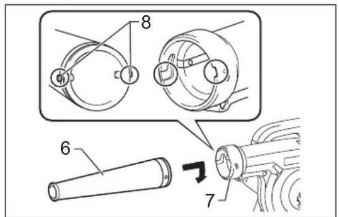
| 1 Switch trigger | 6 Nozzle | 11 Fastener |
| 2 Lock button | 7 Blower outlet | 12 Limit mark |
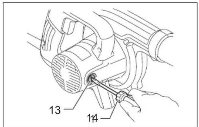
| 3 Speed control screw | 8 Pin | 13 Brush holder cap |
| 4 Higher | 9 Dust bag | 14 Screwdriver |
| 5 Lower | 10 Suction inlet |
SPECIFICATIONS
| Model UB1102 UB1103 | |||
| Capacities | Air pressure 5.7 kPa 0 | -5.7 kPa | |
| Max. air volume 4.1 m | 3/min 0 - 4.1 m | 3/min | |
| No load speed 16,000 min | -1 | 0 - 16,000 min-1 | |
| Overall length | 479 mm | 479 mm | |
| Net weight | 1.9 - 2.2 kg | ||
| Safety class | ☐/II | ||
- Due to our continuing program of research and development, the specifications herein are subject to change without notice.
- Specifications may differ from country to country.
- The weight may differ depending on the attachment(s). The lightest and heaviest combination, according to EPTA-Procedure 01/2014, are shown in the table.
END334-1
Symbols
The followings show the symbols which may be used for the equipment. Be sure that you understand their meaning before use.


Read instruction manual.
DOUBLE INSULATION
Only for EU countries
Due to the presence of hazardous components in the equipment, used electrical and electronic equipment may have a negative impact on the environment and human health.
Do not dispose of electrical and electronic appliances with household waste! In accordance with the European Directive on waste electrical and electronic equipment and its adaptation to national law, used electrical and electronic equipment should be collected separately and delivered to a separate collection point for municipal waste, operating in accordance with the environmental protection regulations. This is indicated by the symbol of the crossed-out wheeled bin placed on the equipment.

Guaranteed sound power level according to EU Outdoor Noise Directive.

Sound power level according to Australia NSW Noise Control Regulation
ENE018-1
Intended use
The tool is intended for blowing dust.
ENF002-2
Power supply
The tool should be connected only to a power supply of the same voltage as indicated on the nameplate, and can only be operated on single-phase AC supply. They are double-insulated and can, therefore, also be used from sockets without earth wire.
GEA010-2
General Power Tool Safety Warnings
WARNING Read all safety warnings, instructions, illustrations and specifications provided with this power tool. Failure to follow all instructions listed below may result in electric shock, fire and/or serious injury.
Save all warnings and instructions for future reference.
The term "power tool" in the warnings refers to your mains-operated (corded) power tool or battery-operated (cordless) power tool.
ENB017-2
ADDITIONAL SAFETY RULES
- Always use protective goggles, a cap and mask when using the blower.
- Never point the nozzle at anyone in the vicinity when using the blower.
-
Always use the dust bag when collecting dust, chips and the like.
-
Do not collect still smoldering cigarette ashes, freshly cut metals shavings, screws, nails and the like.
- Electric shock could occur if used on wet surfaces. Do not expose to rain. Store indoors.
- Never block suction inlet and/or blower outlet. Increased motor revolution may cause dangerous fan breakage.
- The blower is not intended for use by young children or infirm persons without supervision.
- Young children should be supervised to ensure that they do not play with the blower.
SAVE THESE INSTRUCTIONS.
FUNCTIONAL DESCRIPTION

CAUTION:
- Always be sure that the tool is switched off and unplugged before adjusting or checking function on the tool.
Switch action

CAUTION:
- Before plugging in the tool, always check to see that the switch trigger actuates properly and returns to the "OFF" position when released.
For UB1102 (Fig. 1)
To start the tool, simply pull the switch trigger. Release the switch trigger to stop.
For continuous operation, pull the switch trigger, push in the lock button and then release the switch trigger. Switch can be locked in "ON" position for ease of operator comfort during extended use. Apply caution when locking tool in "ON" position and maintain firm grasp on tool.
To stop the tool from the locked position, pull the switch trigger fully, then release it.
For UB1103 (Fig. 2)
To start the tool, simply pull the switch trigger. Tool speed is increased by increasing pressure on the switch trigger. Release the switch trigger to stop. Switch can be locked in "ON" position for ease of operator comfort during extended use. Apply caution when locking tool in "ON" position and maintain firm grasp on tool.
For continuous operation, pull the switch trigger, push in the lock button and then release the switch trigger.
To stop the tool from the locked position, pull the switch trigger fully, then release it.
A speed control screw is provided so that maximum tool speed can be limited (variable). Turn the speed control screw clockwise for higher speed, and counterclockwise for lower speed.
OPERATION

CAUTION:
• Always hold the tool only by the handle when performing an operation. Do not touch the metal part.
- Do not use the tool for blowing air into objects, like rubber rafting, balls or other inflatable products. Increased motor revolution may cause dangerous fan breakage. (Fig. 3)
Blowing (Fig. 4)
For dust blowing, attach nozzle to blower outlet. Turn it clockwise until it clicks.
Dust suction (optional accessory) (Fig. 5 & 6)
For dust suction, fit nozzle onto suction inlet and dust bag onto blower outlet. Turn them clockwise until it clicks. After the bag fills with dust, empty the contents of the dust bag into a dust bin by releasing the fastener.
MAINTENANCE

CAUTION:
• Always be sure that the tool is switched off and unplugged before attempting to perform inspection or maintenance.
- Never use gasoline, benzine, thinner, alcohol or the like. Discoloration, deformation or cracks may result.
Replacing carbon brushes (Fig. 7 & 8)
Remove and check the carbon brushes regularly. Replace when they wear down to the limit mark. Keep the carbon brushes clean and free to slip in the holders. Both carbon brushes should be replaced at the same time. Use only identical carbon brushes.
Use a screwdriver to remove the brush holder caps. Take out the worn carbon brushes, insert the new ones and secure the brush holder caps.
To maintain product SAFETY and RELIABILITY, repairs, any other maintenance or adjustment should be performed by Makita Authorized Service Centers, always using Makita replacement parts.
OPTIONAL ACCESSORIES

CAUTION:
- These accessories or attachments are recommended for use with your Makita tool specified in this manual. The use of any other accessories or attachments might present a risk of injury to persons. Only use accessory or attachment for its stated purpose.
If you need any assistance for more details regarding these accessories, ask your local Makita service center.
- Joint
- Nozzle assembly
- Dust bag assembly
- Flexible hose
- Nozzle assembly (Long size)
NOTE:
- Some items in the list may be included in the tool package as standard accessories. They may differ from country to country.
ENG905-1
Noise
The typical A-weighted noise level determined according to EN62841-1:
Sound pressure level ( LnA ): 86 dB (A)
Sound power level (L WA ): 94 dB (A)
Uncertainty (K): 3 dB (A)
ENG907-1
NOTE:
- The declared noise emission value(s) has been measured in accordance with a standard test method and may be used for comparing one tool with another.
- The declared noise emission value(s) may also be used in a preliminary assessment of exposure.

WARNING:
- Wear ear protection.
- The noise emission during actual use of the power tool can differ from the declared value(s) depending on the ways in which the tool is used especially what kind of workpiece is processed.
- Be sure to identify safety measures to protect the operator that are based on an estimation of exposure in the actual conditions of use (taking account of all parts of the operating cycle such as the times when the tool is switched off and when it is running idle in addition to the trigger time).
ENG900-1
Vibration
The vibration total value (tri-axial vector sum) determined according to EN62841-1:
Work mode: operation without load
Vibration emission ( ah ): 2.5 m/s 2
Uncertainty (K): 1.5 m/s²
ENG901-2
NOTE:
- The declared vibration total value(s) has been measured in accordance with a standard test method and may be used for comparing one tool with another.
- The declared vibration total value(s) may also be used in a preliminary assessment of exposure.

WARNING:
- The vibration emission during actual use of the power tool can differ from the declared value(s) depending on the ways in which the tool is used especially what kind of workpiece is processed.
- Be sure to identify safety measures to protect the operator that are based on an estimation of exposure in the actual conditions of use (taking account of all parts of the operating cycle such as the times when the tool is switched off and when it is running idle in addition to the trigger time).
DECLARATIONS OF CONFORMITY
For European countries only
The Declarations of conformity are included in Annex A to this instruction manual.
Descriptif
DÉCLARATIONS DE CONFORMITÉ
OPTIONELE ACCESSOIRES
LET OP:


- ENGLISH (ORIGINAL INSTRUCTIONS)
- SYMBOLS
- INTENDED USE
- POWER SUPPLY
- GENERAL POWER TOOL SAFETY WARNINGS
- SAVE ALL WARNINGS AND INSTRUCTIONS FOR FUTURE REFERENCE
- ADDITIONAL SAFETY RULES
- SAVE THESE INSTRUCTIONS
- FUNCTIONAL DESCRIPTION
- CAUTION
- SWITCH ACTION
- FOR UB1102 (FIG. 1)
- FOR UB1103 (FIG. 2)
- OPERATION
- BLOWING (FIG. 4)
- DUST SUCTION (OPTIONAL ACCESSORY) (FIG. 5 & 6)
- MAINTENANCE
- REPLACING CARBON BRUSHES (FIG. 7 & 8)
- OPTIONAL ACCESSORIES
- NOTE
- NOISE
- WARNING
- VIBRATION
- DECLARATIONS OF CONFORMITY
- FOR EUROPEAN COUNTRIES ONLY
- DÉCLARATIONS DE CONFORMITÉ
- OPTIONELE ACCESSOIRES
- LET OP
Brand : MAKITA
Model : UB1103
Category : Heat gun