
5973 - Generator HONEYWELL - Free user manual and instructions
Find the device manual for free 5973 HONEYWELL in PDF.


| Product type | Electric generator |
| Brand | Honeywell |
| Model | 5973 |
| Dimensions (L × W × H) | 60 × 45 × 50 cm |
| Weight | 45 kg |
| Fuel | Gasoline |
| Rated power | 3500 W |
| Maximum power | 4000 W |
| Fuel tank capacity | 15 L |
| Runtime (at 50% load) | 10 hours |
| Starting type | Manual and electric |
| Output voltage | 230 V |
| Number of outlets | 2 × 230V outlets, 1 × 12V outlet |
| Noise level | 68 dB(A) |
| Cooling system | Forced air |
| Engine protection | Automatic low oil shutdown |
| Main functions | Backup power, construction site, leisure |
| Routine maintenance | Oil change every 50 hours, air filter cleaning |
| Safety | Overload protection, residual-current circuit breaker |
| Replaceable parts | Air filter, spark plug, oil, battery |
Frequently Asked Questions - 5973 HONEYWELL
User questions about 5973 HONEYWELL
0 question about this device. Answer the ones you know or ask your own.
Ask a new question about this device
Download the instructions for your Generator in PDF format for free! Find your manual 5973 - HONEYWELL and take your electronic device back in hand. On this page are published all the documents necessary for the use of your device. 5973 by HONEYWELL.
USER MANUAL 5973 HONEYWELL
Owner's Manual Portable Generator
DANGER!
DEADLY EXHAUST FUMES! ONLY use OUTSIDE far away from windows, doors and vents!
NOT INTENDED FOR USE IN CRITICAL LIFE SUPPORT APPLICATIONS.
SAVE this Manual. Provide this manual to any operator of the generator.
Table of Contents
Introduction....1
Read this Manual Thoroughly 1
Safety Rules ....1
Standards Index
General Information 4
1.1 Unpacking 4
1.2 Assembly 4
Operation 4
2.1 Know the Generator ....4
2.2 Cord Sets and Connection Plugs 6
2.3 How to Use the Generator 6
2.4 Don't Overload the Generator ....
2.5 Wattage Reference Guide ....8
2.6 Before Starting the Generator 8
2.7 To Start the Engine 9
2.8 Stopping the Engine ....10
2.9 Low Oil Level Shutdown System 10
Maintenance 10
3.1 Performing Scheduled Maintenance ....10
3.2 Maintenance Schedule 10
3.3 Product Specifications 10
3.4 General Recommendations 11
3.5 Service Air Filter 12
3.6 Valve Clearance 13
3.7 General 13
3.8 Long Term Storage 13
3.9 Other Storage Tips ....13
Troubleshooting 14
4.1 Troubleshooting Guide 14
Notes 15
MANUAL DEL USUARIO ...... 19
MANUEL DE L'UTILISATEUR .... 37
WARNING!
California Proposition 65
Engine exhaust and some of its constituents are known to the state of California to cause cancer, birth defects, and other reproductive harm.
WARNING!
California Proposition 65
This product contains or emits chemicals known to the state of California to cause cancer, birth defects, and other reproductive harm.
INTRODUCTION
Thank you for purchasing this Honeywell model portable generator by Generac Power Systems, Inc. This model is a compact, high performance, air-cooled, engine driven generator designed to supply electrical power to operate electrical loads where no utility power is available or in place of utility due to a power outage.
READ THIS MANUAL THOROUGHLY
If any portion of this manual is not understood, contact the nearest Authorized Dealer for starting, operating and servicing procedures.
The operator is responsible for proper and safe use of the equipment. We strongly recommend that the operator read this manual and thoroughly understand all instructions before using the equipment. We also strongly recommend instructing other users to properly start and operate the unit. This prepares them if they need to operate the equipment in an emergency.
The generator can operate safely, efficiently and reliably only if it is properly located, operated and maintained. Before operating or servicing the generator:
- Become familiar with and strictly adhere to all local, state and national codes and regulations.
- Study all safety warnings in this manual and on the product carefully.
- Become familiar with this manual and the unit before use.
The manufacturer cannot anticipate every possible circumstance that might involve a hazard. The warnings in this manual, and on tags and decals affixed to the unit are, therefore, not all inclusive. If using a procedure, work method or operating technique that the manufacturer does not specifically recommend, ensure that it is safe for others. Also make sure the procedure, work method or operating technique utilized does not render the generator unsafe.
THE INFORMATION CONTAINED HEREIN WAS BASED ON MACHINES IN PRODUCTION AT THE TIME OF PUBLICATION. GENERAC RESERVES THE RIGHT TO MODIFY THIS MANUAL AT ANY TIME.
SAFETY RULES
Throughout this publication, and on tags and decals affixed to the generator, DANGER, WARNING, CAUTION and NOTE blocks are used to alert personnel to special instructions about a particular operation that may be hazardous if performed incorrectly or carelessly. Observe them carefully. Their definitions are as follows:
⚠️ DANGER!
INDICATES A HAZARDOUS SITUATION OR ACTION WHICH, IF NOT AVOIDED, WILL RESULT IN DEATH OR SERIOUS INJURY.
WARNING!
Indicates a hazardous situation or action which, if not avoided, could result in death or serious injury.
▲ CAUTION!
Indicates a hazardous situation or action which, if not avoided, could result in minor or moderate injury.
NOTE:
Notes contain additional information important to a procedure and will be found within the regular text body of this manual.
These safety warnings cannot eliminate the hazards that they indicate. Common sense and strict compliance with the special instructions while performing the action or service are essential to preventing accidents.
Four commonly used safety symbols accompany the DANGER, WARNING and CAUTION blocks. The type of information each indicates is as follows:

This symbol points out important safety information that, if not followed, could endanger personal safety and/or property of others.

This symbol points out potential explosion hazard.

This symbol points out potential fire hazard.

This symbol points out potential electrical shock hazard.

Safety Rules
GENERAL HAZARDS
- NEVER operate in an enclosed area, in a vehicle, or indoors EVEN IF doors and windows are open.
- For safety reasons, the manufacturer recommends that the maintenance of this equipment is carried out by an Authorized Dealer. Inspect the generator regularly, and contact the nearest Authorized Dealer for parts needing repair or replacement.
- Operate generator only on level surfaces and where it will not be exposed to excessive moisture, dirt, dust or corrosive vapors.
- Keep hands, feet, clothing, etc., away from drive belts, fans, and other moving parts. Never remove any fan guard or shield while the unit is operating.
- Certain parts of the generator get extremely hot during operation. Keep clear of the generator until it has cooled to avoid severe burns.
- Do NOT operate the generator in the rain.
- Do not alter the construction of the generator or change controls which might create an unsafe operating condition.
- Never start or stop the unit with electrical loads connected to receptacles AND with connected devices turned ON. Start the engine and let it stabilize before connecting electrical loads. Disconnect all electrical loads before shutting down the generator.
- Do not insert objects through unit's cooling slots.
- When working on this equipment, remain alert at all times. Never work on the equipment when physically or mentally fatigued.
- Never use the generator or any of its parts as a step. Stepping on the unit can stress and break parts, and may result in dangerous operating conditions from leaking exhaust gases, fuel leakage, oil leakage, etc.
NOTE:
This generator is equipped with a spark arrestor muffler. The spark arrestor must be maintained in effective working order by the owner/ operator. In the State of California, a spark arrestor is required by law (Section 4442 of the California Public Resources Code). Other states may have similar laws. Federal laws apply on federal lands.
EXHAUST & LOCATION HAZARDS
- Never operate in an enclosed area or indoors! NEVER use in the home, in a vehicle, or in partly enclosed areas such as garages, EVEN IF doors and windows are open! ONLY use outdoors and far from open windows, doors, vents, and in an area that will not accumulate deadly exhaust.

- The engine exhaust fumes contain carbon monoxide, which you cannot see or smell. This poisonous gas, if breathed in sufficient concentrations, can cause unconsciousness or even death.
- Adequate, unobstructed flow of cooling and ventilating air is critical to correct generator operation. Do not alter the installation or permit even partial blockage of ventilation provisions, as this can seriously affect safe operation of the generator. The generator MUST be operated outdoors.
- This exhaust system must be properly maintained. Do nothing that might render the exhaust system unsafe or in noncompliance with any local codes and/or standards.
- Always use a battery operated carbon monoxide alarm indoors, installed according to the manufacturers instructions.
- If you start to feel sick, dizzy, or weak after the generator has been running, move to fresh air IMMEDIATELY. See a doctor, as you could have carbon monoxide poisoning.
ELECTRICAL HAZARDS
- The generator produces dangerously high voltage when in operation. Avoid contact with bare wires, terminals, connections, etc., while the unit is running, even on equipment connected to the generator. Ensure all appropriate covers, guards and barriers are in place before operating the generator.
- Never handle any kind of electrical cord or device while standing in water, while barefoot or while hands or feet are wet. DANGEROUS ELECTRICAL SHOCK MAY RESULT.
- The National Electric Code (NEC) requires the frame and external electrically conductive parts of the generator be properly connected to an approved earth ground. Local electrical codes may also require proper grounding of the generator. Consult with a local electrician for grounding requirements in the area.
- Use a ground fault circuit interrupter in any damp or highly conductive area (such as metal decking or steel work).
- Do not use worn, bare, frayed or otherwise damaged electrical cord sets with the generator.
- Before performing any maintenance on the generator, disconnect the engine starting battery (if equipped) to prevent accidental start up. Disconnect the cable from the battery post indicated by a NEGATIVE, NEG or (−) first. Reconnect that cable last.
- In case of accident caused by electric shock, immediately shut down the source of electrical power. If this is not possible, attempt to free the victim from the live conductor. AVOID DIRECT CONTACT WITH THE VICTIM. Use a non-conducting implement, such as a rope or board, to free the victim from the live conductor. If the victim is unconscious, apply first aid and get immediate medical help.
FIRE HAZARDS
- Gasoline is highly FLAMMABLE and its vapors are EXPLOSIVE. Do not permit smoking, open flames, sparks or heat in the vicinity while handling gasoline.
- Never add fuel while unit is running or hot. Allow engine to cool completely before adding fuel.
- Never fill fuel tank indoors. Comply with all laws regulating storage and handling of gasoline.
- Do not overfill the fuel tank. Always allow room for fuel expansion. If tank is over-filled, fuel can overflow onto a hot engine and cause FIRE or an EXPLOSION. Never store generator with fuel in tank where gasoline vapors might reach an open flame, spark or pilot light (as on a furnace, water heater or clothes dryer). FIRE or EXPLOSION may result. Allow unit to cool entirely before storage.
- Wipe up any fuel or oil spills immediately. Ensure that no combustible materials are left on or near the generator. Keep the area surrounding the generator clean and free from debris and keep a clearance of five (5) feet on all side to allow for proper ventilation of the generator.
- Do not insert objects through unit's cooling slots.
- Do not operate the generator if connected electrical devices overheat, if electrical output is lost, if engine or generator sparks or if flames or smoke are observed while unit is running.
- Keep a fire extinguisher near the generator at all times.
STANDARDS INDEX
- National Fire Protection Association (NFPA) 70: The NATIONAL ELECTRIC CODE (NEC) available from www.nfpa.org
- National Fire Protection Association (NFPA) 5000: BUILDING CONSTRUCTION AND SAFETY CODE available from www.nfpa.org
- International Building Code available from www.iccsafe.org
- Agricultural Wiring Handbook available from www.rerc.org, Rural Electricity Resource Council P.O. Box 309 Wilmington, OH 45177-0309
- ASAE EP-364.2 Installation and Maintenance of Farm Standby Electric Power available from www.asabe.org, American Society of Agricultural & Biological Engineers 2950 Niles Road, St. Joseph, MI 49085
This list is not all inclusive. Check with the Authority Having Local Jurisdiction (AHJ) for any local codes or standards which may be applicable to your jurisdiction.
| MODEL NO: | |
| SERIAL NO: |
Unit ID Location

General Information
1.1 UNPACKING
- Remove all packaging material.
- Remove the accessory foam pack.
- Remove the generator from the carton.
1.1.1 ACCESSORY BOX
Check all contents. If any parts are missing or damaged, locate an authorized dealer at 1-855-GEN-INFO.
• 1 - Quick Setup Guide
• 1 - Owner's manual
• 1 - Oil funnel
• 1 - Oil SAE 30
- 2 - 8" Wheels (A)
• 1 - Axle (B)
• 2 - Frame Feet (C)
• 2 - Handles with grips (left (D) and right (E))
• 1 - Hardware Bag
-4-M8-1.25×43 Bolts (G)
- 4 - M6-1.0 x 37 Step Bolt (l)
- 2 - Cotter Pins (F)
- 4 - M8-1.25 Hex Flange Nuts (H)
- 4 - M6-1.0 Acorn Nuts (J)
• 3 - Product Registration Cards (English, Spanish, French)
1.1.2 REQUIRED TOOLS
• 1-12 mm box wrench
• 1- Ratchet
- 2- Sockets
- 1- 10 mm socket
- 1- 12 mm socket
1.2 ASSEMBLY
The generator requires some assembly prior to using it. If problems arise when assembling the generator, please call the Generator Helpline at 1-855-GEN-INFO.
1.2.1 ASSEMBLING THE ACCESSORY KIT
The wheels are designed to the unit to greatly improve the portability of the generator.
NOTE:
The wheels are not intended for over-the-road-use.
-
Refer to Figure 1 to install the wheels (A) as shown.
-
Slide the axle (B) through the frame brackets.
-
Slide on the wheels (A) then install the cotter pins (F).
-
Refer to Figure 1 to install the frame feet (C) as shown.
- Place each frame foot (C) under the frame and secure with two M8-1.25 x 40 bolts (G) and two M8 x 1.25 hex flange nuts (H).
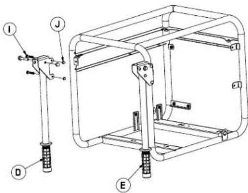
- Refer to Figure 2 to install the handle assembly (D and E) as shown.
- Secure each handle assembly (D and E) to the frame using the two M6-1.0 x 40 bolts (I) and two M6-1.0 acorn nuts (J).
Figure 1 – Wheel Assembly

Figure 2 - Handle Kit
2.1 KNOW THE GENERATOR
Read the Owner's Manual and Safety Rules before operating this generator.
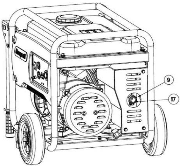
Compare the generator to Figures 3 through 6 to become familiarized with the locations of various controls and adjustments. Save this manual for future reference.
-
120 Volt AC, 20 Amp, Duplex Receptacle – Supplies electrical power for the operation of 120 Volt AC, 20 Amp, single-phase, 60 Hz electrical lighting, appliance, tool and motor loads.
California Models - GFCI Duplex Receptacle - Provides protection within internal Ground Fault Circuit Interrupter complete with a press to "Test" and "Reset" button. -
120/240V AC, 20 Amp Locking Receptacle – Supplies electrical power for the operation of 120 and/or 240 volt AC, 20 amp, single-phase, 60 Hz, electrical lighting, appliance, tool and motor loads.
-
Circuit Breakers (AC) – Each receptacle is provided with a 2-pole, 14 amp circuit breaker to protect the generator against electrical overload.
- Air Filter – Filters intake air as it is drawn into the engine.
- Choke Lever – Used when starting a cold engine.
- Fuel Tank – Tank holds 2.9 U.S. gallons of fuel.
- Grounding Lug – Ground the generator to an approved earth ground here. See "Grounding the Generator" for details.
- On/OFF Switch – Controls the operation of the generator.
- Muffler – Quiets the engine.
- Handles – Pivot and retract for storage.
- Gas Cap – Fuel fill location.
- Fuel Gauge – Shows fuel level in tank.
- Oil Check/Fill – Check and fill oil here.
- Recoil Starter – Use to start engine manually.
- Fuel Shut Off – Valve between fuel tank and carburetor.
- Oil Drain Plug – Used to drain engine oil.
- Spark Arrestor – Reduces fire hazard by containing sparks.
Figure 3 - Control Panel (49 State/CSA Shown)
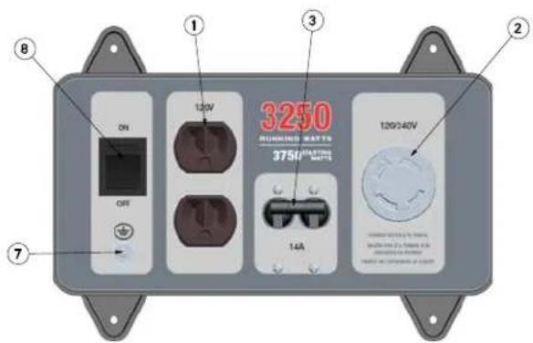
Figure 4 - Generator Controls

Figure 5 - Generator Controls
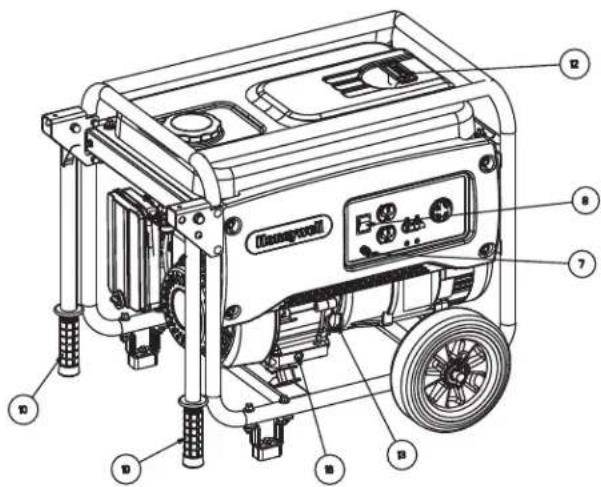
Figure 6 - Generator Controls

2.2 CORD SETS AND CONNECTION PLUGS
2.2.1 120 VAC, 20 AMP, DUPLEX RECEPTACLE
This is a 120 Volt outlet protected against overload by a 14 Amp circuit breaker (Figure 7). Use each socket to power 120 Volt AC, single phase, 60 Hz electrical loads requiring up to a combined 1680 watts (1.68 kW) or 14 Amps of current. Use only high quality, well-insulated, 3-wire grounded cord sets rated for 125 Volts at 20 Amps (or greater).
Keep extension cords as short as possible, preferably less than 15 feet long, to prevent voltage drop and possible overheating of wires.
Figure 7 - 120 Volt AC, 20 Amp, Duplex Receptacle


2.2.2 120 VAC, 20 AMP, GFCI DUPLEX RECEPTACLE (CARB ONLY)
This is a 120 Volt outlet protected against overload by a 14 Amp circuit breaker (Figure 8). Use each socket to power 120 Volt AC, single phase, 60 Hz electrical loads requiring up to a combined 1680 watts (1.68 kW) or 14 Amps of current. Use only high quality, well-insulated, 3-wire grounded cord sets rated for 125 Volts at 20 Amps (or greater).
Keep extension cords as short as possible to prevent voltage drop and possible overheating of wires.
Figure 8 - 120 Volt AC, 20 Amp, GFCI Duplex Receptacle

natural_image
Pure electrical circuit lines without any symbols2.2.3 120/240 VAC, 20 AMP TWISTLOCK RECEPTACLE
This is a 120/240 Volt outlet protected against overload by a 14 Amp circuit breaker (Figure 9). Connect a suitable 4-wire grounded cord set to the plug and to the desired load. The cord set should be rated for 250 volts at 20 amps (or greater) if the 120/240 receptacle is used along with 120 volt receptacle. The total load drawn must not exceed the data label ratings.
Figure 9 - 120/240 VAC, 20 Amp Receptacle

natural_image
Circular diagram with four black curved segments arranged in a ring, no text or symbols present.IMPORTANT: Do not overload the generator. Also, do not overload individual panel receptacles. These outlets are protected against overload with circuit breakers. If amperage rating of any circuit breaker is exceeded, that breaker opens and electrical output to that receptacle is lost. Read “Don’t Overload the Generator” carefully.
2.3 HOW TO USE THE GENERATOR
If there are any problems operating the generator, please call the generator helpline at 1-888-436-3722.
⚠️ DANGER!
Never operate in an enclosed area or indoors! NEVER use in the home, in a vehicle, or in partly enclosed areas such as garages, EVEN IF doors and windows are open! ONLY use outdoors and far from open windows, doors, vents, and in an area that will not accumulate deadly exhaust.
The engine exhaust fumes contain carbon monoxide, which can you cannot see or smell. This poisonous gas, if breathed in sufficient concentrations, can cause unconsciousness or even death.
Adequate, unobstructed flow of cooling and ventilating air is critical to correct generator operation. Do not alter the installation or permit even partial blockage of ventilation provisions, as this can seriously affect safe operation of the generator. The generator MUST be operated outdoors.
This exhaust system must be properly maintained. Do nothing that might render the exhaust system unsafe or in noncompliance with any local codes and/or standards.
Always use a battery operated carbon monoxide alarm indoors, installed according to the manufacturers instructions.

2.3.1 GROUNDING THE GENERATOR WHEN USED AS A PORTABLE
This generator has an equipment ground that connects the generator frame components to the ground terminals on the AC output receptacles (see NEC 250.34 (A) for explanation). This allows the generator to be used as a portable without grounding the frame of the generator as specified in NEC 250.34.
Figure 10 - Grounding the Generator

Special Requirements
There may be Federal or State Occupational Safety and Health Administration (OSHA) regulations, local codes, or ordinances that apply to the intended use of the generator.
Please consult a qualified electrician, electrical inspector, or the local agency having jurisdiction:
- In some areas, generators are required to be registered with local utility companies.
- If the generator is used at a construction site, there may be additional regulations which must be observed.
2.3.2 CONNECTING THE GENERATOR TO A BUILDING'S ELECTRICAL SYSTEM
When connecting directly to a building's electrical system, it is recommended that a manual transfer switch is used. Connections for a portable generator to a building's electrical system must be made by a qualified electrician and in strict compliance with all national and local electrical codes and laws.
2.3.3 CONNECTING ELECTRICAL LOADS
DO NOT connect 240 Volt loads to 120 Volt receptacles. DO NOT connect 3-phase loads to the generator. DO NOT connect 50 Hz loads to the generator.
- Let engine stabilize and warm up for a few minutes after starting.
- Plug in and turn on the desired 120 or 240 Volt AC, single phase, 60 Hz electrical loads.
- Add up the rated watts (or amps) of all loads to be connected at one time. This total should not be greater than (a) the rated wattage/amperage capacity of the generator or (b) circuit breaker rating of the receptacle supplying the power. See "Don't Overload the Generator".
2.4 DON'T OVERLOAD THE GENERATOR
Overloading a generator in excess of its rated wattage capacity can result in damage to the generator and to connected electrical devices. Observe the following to prevent overloading the unit:
- Add up the total wattage of all electrical devices to be connected at one time. This total should NOT be greater than the generator's wattage capacity.
- The rated wattage of lights can be taken from light bulbs. The rated wattage of tools, appliances and motors can usually be found on a data label or decal affixed to the device.
- If the appliance, tool or motor does not give wattage, multiply volts times ampere rating to determine watts (volts x amps = watts).
-
Some electric motors, such as induction types, require about three times more watts of power for starting than for running. This surge of power lasts only a few seconds when starting such motors. Make sure to allow for high starting wattage when selecting electrical devices to connect to the generator:
-
Figure the watts needed to start the largest motor.
- Add to that figure the running watts of all other connected loads.
The Wattage Reference Guide is provided to assist in determining how many items the generator can operate at one time.
NOTE:
All figures are approximate. See data label on appliance for wattage requirements.
2.5 WATTAGE REFERENCE GUIDE
Device ...... Running Watts
*Air Conditioner (12,000 Btu).... 1700
*Air Conditioner (24,000 Btu)....3800
*Air Conditioner (40,000 Btu)....6000
Battery Charger (20 Amp)....500
Belt Sander (3") 1000
Chain Saw 1200
Circular Saw (6-1/2") 800 to 1000
*Clothes Dryer (Electric) 5750
*Clothes Dryer (Gas) 700
*Clothes Washer 1150
Coffee Maker 1750
*Compressor (1 HP)....2000
*Compressor (3/4 HP) 1800
*Compressor (1/2 HP) 1400
Curling Iron. 700
*Dehumidifier 650
Disc Sander (9")....1200
Edge Trimmer 500
Electric Blanket 400
Electric Nail Gun 1200
Electric Range (per element)....1500
Electric Skillet 1250
*Freezer....700
*Furnace Fan (3/5 HP) 875
*Garage Door Opener ....500 to 750
Hair Dryer....1200
Hand Drill 250 to 1100
Hedge Trimmer....450
Impact Wrench 500
Iron....1200
*Jet Pump 800
Lawn Mower....1200
Light Bulb 100
Microwave Oven....700 to 1000
*Milk Cooler 1100
Oil Burner on Furnace 300
Oil Fired Space Heater (140,000 Btu) 400
Oil Fired Space Heater (85,000 Btu) 225
Oil Fired Space Heater (30,000 Btu) 150
*Paint Sprayer, Airless (1/3 HP) 600
Paint Sprayer, Airless (handheld)....150
Radio 50 to 200
*Refrigerator....700
Slow Cooker....200
*Submersible Pump (1-1/2 HP) 2800
*Submersible Pump (1 HP) 2000
*Submersible Pump (1/2 HP).... 1500
*Sump Pump ....800 to 1050
*Table Saw (10") 1750 to 2000
Television 200 to 500
Toaster 1000 to 1650
Weed Trimmer 500
* Allow 3 times the listed watts for starting these devices.
2.6 BEFORE STARTING THE GENERATOR
Prior to operating the generator, engine oil and gasoline will need to be added, as follows:
2.6.1 ADDING ENGINE OIL
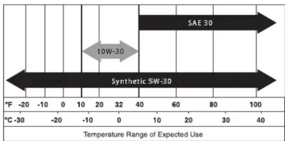
All oil should meet minimum American Petroleum Institute (API) Service Class SJ, SL or better. Use no special additives. Select the oil's viscosity grade according to the expected operating temperature (also see chart). The manufacturer recommends breaking in the engine with petroleum oil. Then at the first oil service interval, synthetic oil can be used from then on.
- Above 40^ F, use SAE 30
• Below 40°F and down to 10°F, use 10W-30
• Below 10°F, use synthetic 5W-30
▲ CAUTION!
Any attempt to crank or start the engine before it has been properly serviced with the recommended oil may result in an engine failure.
- Place generator on a level surface (not to exceed 15^ in any direction).
- Clean area around oil fill and remove oil fill cap and dipstick.
- Wipe dipstick clean.
- Slowly fill engine with oil through the oil fill opening until it reaches the high mark on the dipstick (Figure 11). Stop filling occasionally to check oil level. Be careful not to over fill.
- Install oil fill cap and finger tighten securely.
- Check engine oil level before starting each time thereafter.
Figure 11 - Dipstick

Gasoline is highly FLAMMABLE and its vapors are EXPLOSIVE. Never fill fuel tank indoors. Never fill fuel tank when engine is running or hot. Allow engine to cool entirely before filling fuel tank. Avoid spilling gasoline on HOT engine. DO NOT light a cigarette or smoke when filling the fuel tank.
WARNING!

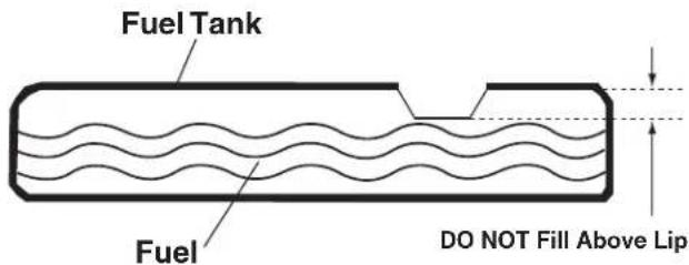
Do not overfill the fuel tank. Always leave room for fuel expansion. If the fuel tank is overfilled, fuel can overflow onto a HOT engine and cause FIRE or EXPLOSION.
- Use regular UNLEADED gasoline with the generator engine. Do not use any gasoline with more than 10% added Ethanol, and never use E85 gasoline. Do not mix oil with gasoline.
- Clean area around fuel fill cap, remove cap.
- Slowly add unleaded regular gasoline to fuel tank. Be careful not to overfill (Figure 12).
• Install fuel cap and wipe up any spilled gasoline.
Figure 12 - Fuel Tank
IMPORTANT: It is important to prevent gum deposits from forming in fuel system parts such as the carburetor, fuel hose or tank during storage. Alcohol-blended fuels (called gasohol, ethanol or methanol) can attract moisture, which leads to separation and formation of acids during storage. Acidic gas can damage the fuel system of an engine while in storage. To avoid engine problems, the fuel system should be emptied before storage of 30 days or longer. See the "Storage" section. Never use engine or carburetor cleaner products in the fuel tank as permanent damage may occur.
2.7 TO START THE ENGINE
WARNING!

Never start or stop engine with electrical devices plugged into the receptacles AND devices turned on.
- Check oil.
- Check gas.
- Unplug all electrical loads from the unit's receptacles before starting the engine.
- Place generator on a level surface (not to exceed 15^ in any direction).
- OPEN the Fuel Shut-off Valve (Figure 13).
- Turn engine ON/OFF switch to ON position (Figure 13).
- Move engine CHOKE lever to the FULL CHOKE position (Figure 13).
- To start engine, firmly grasp the recoil handle and pull slowly until increased resistance is felt. Pull rapidly up and away.
- When engine starts, move choke lever to 1/2-CHOKE position until engine runs smoothly and then fully into RUN position. If engine falters, move choke back out to 1/2-CHOKE position until engine runs smoothly and then to RUN position.
NOTE:
If engine fires, but does not continue to run, move choke lever to the START position and repeat starting instructions.
Figure 13 - Engine Controls

2.8 STOPPING THE ENGINE
- Shut off all loads, then unplug the electrical loads from generator panel receptacles. Never start or stop the engine with electrical devices plugged in and turned on.
- Let engine run at no-load for several minutes to stabilize the internal temperatures of engine and generator.
- Move ON/OFF switch to OFF position.
- Close fuel valve.
2.9 LOW OIL LEVEL SHUTDOWN SYSTEM
The engine is equipped with a low oil level sensor that shuts down the engine automatically when the oil level drops below a specified level. If the engine shuts down by itself and the fuel tank has enough gasoline, check engine oil level.
2.9.1 SENSING LOW OIL LEVEL
If the system senses a low oil level during operation, the engine shuts down. The engine will not run until the oil has been refilled to the proper level.
3.1 PERFORMING SCHEDULED MAINTENANCE
It is important to perform service as specified in the Maintenance Schedule for proper generator operation, and to ensure that the generator complies with the applicable emission standards for the duration of its useful life. Service and repairs may be performed by any capable person or repair shop. Additionally, emissions critical maintenance must be performed as scheduled in order for the Emissions Warranty to be valid. Emissions critical maintenance consists of servicing the air filter and spark plugs in accordance with the Maintenance Schedule.
Follow the calendar intervals. More frequent service is required when operating in adverse conditions noted below.
Check Oil Level At Each Use
Change Oil ¥ *Every 50 Hours
Check Valve Clearance ***Every Season
Service Air Filter **Every 25 Hours
Replace Spark Plug ****Every 100 Hours
¥ Change oil after first 20 hours of operation.
* Change oil every month when operating under heavy load or in high temperatures.
** Clean more often under dirty or dusty operating conditions. Replace air filter parts if they cannot be adequately cleaned.
*** Check valve clearance and adjust if necessary after first 50 hours of operation and every 100 hours thereafter.
**** Clean and re-gap spark plug every 50 hours.
3.3 PRODUCT SPECIFICATIONS
3.3.1 GENERATOR SPECIFICATIONS
Rated. Power 3.25 kW**
Surge Power 3.75 kW
Rated AC Voltage 120/240
Rated Current....27/13.5 Amps**
Rated Frequency 60 Hz @ 3600 RPM
Phase ...... Single Phase
* Operating Temperature Range: 0 °F (-18 °C) to 110 °F (43 °C). When operated above 77 °F (25 °C) there may be a decrease in power.
** Maximum wattage is subject to, and limited by, such factors as fuel Btu content, ambient temperature, altitude, engine condition, etc.. Maximum power decreases about 3.5% for each 1,000 feet above sea level; and will also decrease about 1% for each 6°C (10°F) above 16°C (60°F) ambient temperature.
3.3.2 ENGINE SPECIFICATIONS
Displacement....208 cc
Spark Plug Type....F6TC
Spark Plug Gap 0.030 inch or (0.76 mm)
Gasoline Capacity 11 L (2.9 U.S. gallons)
Oil Type..... See Chart in "Before Starting the Generator" Section
Oil Capacity 0.6 L (0.634 Qts.)
Run Time....7.5 Hours at 1/2 Load
Class II Emission Certified*
* The engine manufacturer must warrant the emission control system for a period of two years. This warranty coverage is in addition to the warranty provided by Generac, and may cover the engine even if Generac's warranty does not.
3.3.3 EMISSIONS INFORMATION
The Environmental Protection Agency (and California Air Resource Board for generators certified to CA standards) require(s) that this generator comply with exhaust and evaporative emission standards. Locate the emissions compliance decal on the engine to determine what standards the generator meets. This generator is certified to operate on gasoline. The emission control system consists of the following:
• Air Induction System
- Air Cleaner
- Fuel System
- Carburetor
- Fuel Tank / Cap
- Fuel Lines
– Evaporative Vent Lines
— Carbon Canister (for CA engines only)
- Ignition System
- Spark Plug
- Ignition Module
- Flywheel
- Exhaust System
- Muffler
- Catalyst
— Secondary Air Valve
The fuel system on this generator may be influenced by operation at higher altitudes. Proper operation can be ensured by installing an altitude kit when required. See the table below to determine when an altitude kit is required. Operating this generator without the proper altitude kit installed may increase the engine's emissions and decrease fuel economy and performance. Kits may be obtained from any Dealer, and should be installed by a qualified individual.
| Unit Altitude Range* Kit Part Number | ||
| HW3250 | 0 - 3000 ft Not Required | |
| 3000 - 6500 ft** 0J6 | 993 | |
| * Elevation above sea level** At elevations above 6500 ft, the engine may experience decreased performance. | ||
3.4 GENERAL RECOMMENDATIONS
The warranty of the generator does not cover items that have been subjected to operator abuse or negligence. To receive full value from the warranty, the operator must maintain the generator as instructed in this manual.
Some adjustments will need to be made periodically to properly maintain the generator.
All adjustments in the Maintenance section of this manual should be made at least once each season. Follow the requirements in the "Maintenance Schedule".
NOTE:
Once a year replace the spark plug and replace the air filter. A new spark plug and clean air filter assure proper fuel-air mixture and help the engine run better and last longer.
3.4.1 GENERATOR MAINTENANCE
Generator maintenance consists of keeping the unit clean and dry. Operate and store the unit in a clean dry environment where it will not be exposed to excessive dust, dirt, moisture or any corrosive vapors. Cooling air slots in the generator must not become clogged with snow, leaves, or any other foreign material.
Check the cleanliness of the generator frequently and clean when dust, dirt, oil, moisture or other foreign substances are visible on its exterior surface.
▲ CAUTION!
Never insert any object or tool through the air cooling slots, even if the engine is not running.
NOTE:
DO NOT use a garden hose to clean generator. Water can enter the engine fuel system and cause problems. In addition, if water enters the generator through cooling air slots, some water will be retained in voids and crevices of the rotor and stator winding insulation. Water and dirt buildup on the generator internal windings will eventually decrease the insulation resistance of these windings.
3.4.2 TO CLEAN THE GENERATOR
- Use a damp cloth to wipe exterior surfaces clean.
- A soft, bristle brush may be used to loosen caked on dirt, oil, etc.
- A vacuum cleaner may be used to pick up loose dirt and debris.
- Low pressure air (not to exceed 25 psi) may be used to blow away dirt. Inspect cooling air slots and openings on the generator. These openings must be kept clean and unobstructed.
3.4.3 ENGINE MAINTENANCE
WARNING!
When working on the generator, always disconnect the spark plug wire from spark plug and keep wire away from spark plug.
3.4.4 CHECKING OIL LEVEL
See the “Before Starting the Generator” section for information on checking the oil level. The oil level should be checked before each use, or at least every eight hours of operation. Keep the oil level maintained.
3.4.5 CHANGING THE OIL
Change the oil after the first 20 hours of operation, then every 50 hours thereafter. If running this unit under dirty or dusty conditions, or in extremely hot weather, change the oil more often.
▲CAUTION!
Hot oil may cause burns. Allow engine to cool before draining oil. Avoid prolonged or repeated skin exposure with used oil. Thoroughly wash exposed areas with soap.
Use the following instructions to change the oil after the engine cools down:
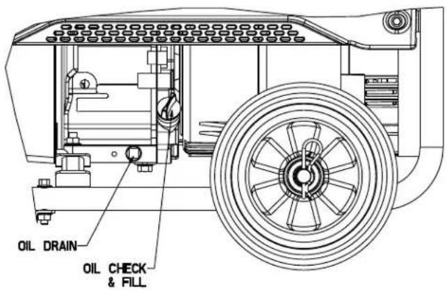
- Clean area around oil drain plug (Figure 14).
- Remove oil drain plug from engine and oil fill plug to drain oil completely into a suitable container.
- When oil has completely drained, install oil drain plug and tighten securely.
- Fill engine with recommended oil. (See "Before Starting the Generator" for oil recommendations).
- Wipe up any spilled oil.
- Dispose of used oil at a proper collection center.
Maintenance
Figure 14 - Oil Drain, Check & Fill
3.4.6 REPLACING THE SPARK PLUG
Use spark plug F6TC. Replace the plug every 100 hours of operation. This will help the engine start easier and run better.
- Stop the engine and pull the spark plug wire off of the spark plug.
- Clean the area around the spark plug and remove it from the cylinder head.
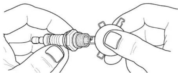
- Set the spark plug's gap to 0.76 mm (0.030 in.). Install the correctly gapped spark plug into the cylinder head and torque to 15 ft/lbs. (Figure 15).
Figure 15 - Spark Plug Gap
natural_image
Line drawing of hands holding a screwdriver (no text or symbols present)3.4.7 SPARK ARRESTOR
The engine exhaust muffler has a spark arrestor screen. Inspect and clean the screen at least once each year (Figure 16). If unit is used regularly, inspect and clean more often.
NOTE:
If using the generator on any forest-covered, brush-covered or grass-covered unimproved land, it must equipped with a spark arrestor. The spark arrestor must be maintained in good condition by the owner/operator.
Clean and inspect the spark arrestor as follows:
- Remove clamp and spark arrestor from muffler.
-
Inspect screen and replace if torn, perforated or otherwise damaged. DO NOT USE a defective screen. If screen is not damaged, clean it with commercial solvent.
-
Replace the spark arrestor and clamp.
Figure 16 - Spark Arrestor

3.5 SERVICE AIR FILTER
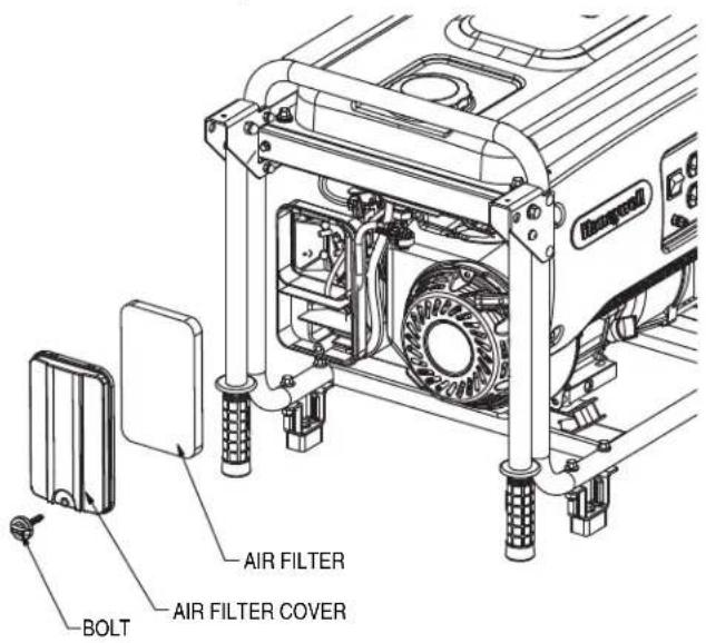
The engine will not run properly and may be damaged if using a dirty air filter. Clean the air filter every 25 hours (Figure 17). Clean or replace more often if operating under dusty conditions.
- Remove air filter cover.
- Wash in soapy water. Squeeze filter dry in clean cloth (DO NOT TWIST).
- Clean air filter cover before re-installing it.
Figure 17 - Air Filter
3.6 VALVE CLEARANCE
- Intake — 0.10 ± 0.02mm (cold), (0.004" ± 0.0008" inches)
Exhaust — 0.15 ± 0.02mm (cold) (0.006" ± 0.0008" inches)
After the first 50 hours of operation, check the valve clearance in the engine and adjust if necessary.
Important: If feeling uncomfortable about doing this procedure or the proper tools are not available, please take the generator to the nearest service center to have the valve clearance adjusted. This is a very important step to ensure longest life for the engine.
3.7 GENERAL
The generator should be started at least once every 30 days and be allowed to run at least 30 minutes. If this cannot be done and the unit must be stored for more than 30 days, use the following information as a guide to prepare it for storage.
▲ WARNING!

NEVER store engine with fuel in tank indoors or in enclosed, poorly ventilated areas where fumes may reach an open flame, spark or pilot light as on a furnace, water heater, clothes dryer or other gas appliance.
3.8 LONG TERM STORAGE
It is important to prevent gum deposits from forming in essential fuel system parts such as the carburetor, fuel hose or tank during storage. Also, experience indicates that alcohol-blended fuels (called gasohol, ethanol or methanol) can attract moisture, which leads to separation and formation of acids during storage. Acidic gas can damage the fuel system of an engine while in storage.
To avoid engine problems, the fuel system should be emptied before storage of 30 days or longer, as follows:
- Remove all gasoline from the fuel tank.
WARNING!

Drain fuel into approved container outdoors, away from open flame. Be sure engine is cool. Do not smoke near fuel.
- Start and run engine until engine stops from lack of fuel.
- Drain oil from crankcase after the engine cools down. Refill with recommended grade.
- Remove spark plug and pour about 1/2 ounce (15 ml) of engine oil into the cylinder. Cover spark plug hole with rag. Pull the recoil starter a couple times to lubricate the piston rings and cylinder bore.
CAUTION!

Avoid spray from spark plug hole when cranking engine.
- Install and tighten spark plug. Do not connect spark plug wire.
- Clean the generator outer surfaces. Check that cooling air slots and openings on generator are open and unobstructed.
- Store the unit in a clean, dry place.
3.9 OTHER STORAGE TIPS
- Do not store gasoline from one season to another.
- Replace the gasoline can if it starts to rust. Rust and/or dirt in the gasoline will cause problems with the carburetor and fuel system.
- If possible, store the unit indoors and cover it to give protection from dust and dirt. BE SURE TO EMPTY THE FUEL TANK.
- If it is not practical to empty the fuel tank and the unit is to be stored for some time, use a commercially available fuel stabilizer added to the gasoline to increase the life of the gasoline.
- Cover the unit with a suitable protective cover that does not retain moisture.
WARNING!

NEVER cover the generator while engine and exhaust areas are warm.
4.1 TROUBLESHOOTING GUIDE
| PROBLEM CAUSE CORRECTION | ||
| Engine is running, but no AC output is available. | 1. Circuit breaker is open.2. Poor connection or defective cord set.3. Connected device is bad.4. Fault in generator. | 1. Reset circuit breaker.2. Check and repair.3. Connect another device that is in good condition.4. Contact Authorized Service Facility. |
| Engine runs good but bogs down when loads are connected. | 1. Short circuit in a connected load.2. Generator is overloaded.3. Engine speed is too slow.4. Shorted generator circuit. | 1. Disconnect shorted electrical load.2. See “Don’t Overload the Generator”.3. Contact Authorized Service Facility.4. Contact Authorized Service Facility. |
| Engine will not start; or starts and runs rough. | 1. Dirty air filter.2. Out of gasoline.3. Stale gasoline.4. Spark plug wire not connected to spark plug.5. Bad spark plug.6. Water in gasoline.7. Over-choking.8. Low oil level.9. Excessive rich fuel mixture.10. Intake valve stuck open or closed.11. Engine has lost compression. | 1. Clean or replace air filter.2. Fill fuel tank.3. Drain fuel tank and fill with fresh fuel.4. Connect wire to spark plug.5. Replace spark plug.6. Drain fuel tank; fill with fresh fuel.7. Put choke knob to No Choke position.8. Fill crankcase to proper level.9. Contact Authorized Service Facility.10. Contact Authorized Service Facility.11. Contact Authorized Service Facility. |
| Engine shuts down during operation. | 1. Out of gasoline.2. Low oil level.3. Fault in engine. | 1. Fill fuel tank.2. Fill crankcase to proper level.3. Contact Authorized Service Facility. |
| Engine lacks power. 1. Load is too high. | 2. Dirty air filter.3. Engine needs to be serviced. | 1. See “Don’t Overload the Generator”.2. Replace air filter.3. Contact Authorized Service Facility. |
| Engine “hunts” or falters. 1. Choke is opened too soon.2. Carburetor is running too rich or too lean. | 1. Move choke to halfway position until engine runs smoothly.2. Contact Authorized Service Facility. | |
Notes
Notes
Notes
Manual del Usuario
Generador portátil
▲ PELIGRO
LEA ESTE MANUAL EN SU TOTALIDAD
Hearing protection recommended.
PRECAUCIÓN
Figura 2 – Kit de la manija

Figura 5 - Controles del generador

Figura 6 - Controles del generador
natural_image
Pure electrical circuit lines without any symbols2.2.3 RECEPTÁCULO TWISTLOCK DE 120/240 VAC, 20 AMPERIOS
natural_image
Circular diagram with four black curved segments arranged in a ring, no text or symbols present.natural_image
Line drawing of hands holding a spark plug (no text or symbols)3.4.7 SUPRESOR DE CHISPAS
Introduction......39
Lire attentivement ce manuel .... 39
LIRE ATTENTIVEMENT CE MANUEL
2.1 CONNAÎTRE LA GÉNÉRATRICE
2.2 CORDONS ET PRISES DE CONNEXION
2.2.1 PRISE DOUBLE DE 120 VOLTS CA, 20 AMP
natural_image
Two identical electrical socket symbols with black and white markings, no text or labels present.2.2.2 PRISE DOUBLE DU DISJONCTEUR GFCI DE 120 VOLTS CA, 20 AMP (CARB SEULEMENT)
natural_image
Pure electrical circuit lines without any symbols2.2.3 PRISE À VERROUILLAGE PAR ROTATION DE 120/240 VOLTS CA, 20 AMP
natural_image
Circular diagram with four black curved segments arranged in a ring, no text or symbols present.3.3 SPÉCIFICATIONS DU PRODUIT
3.3.1 SPÉCIFICATIONS DE LA GÉNÉRATRICE
natural_image
Line drawing of two hands holding a screwdriver (no text or symbols present)3.4.7 PARE-ÉTINCELLES
- Owner's Manual Portable Generator
- DANGER!
- Table of Contents
- Introduction....1
- Read this Manual Thoroughly 1
- Safety Rules ....1
- General Information 4
- Operation 4
- Maintenance 10
- Troubleshooting 14
- Notes 15
- MANUAL DEL USUARIO ...... 19
- MANUEL DE L'UTILISATEUR .... 37
- WARNING!
- INTRODUCTION
- READ THIS MANUAL THOROUGHLY
- SAFETY RULES
- ⚠️ DANGER!
- ▲ CAUTION!
- NOTE:
- GENERAL HAZARDS
- EXHAUST & LOCATION HAZARDS
- ELECTRICAL HAZARDS
- FIRE HAZARDS
- STANDARDS INDEX
- General Information
- UNPACKING
- ACCESSORY BOX
- REQUIRED TOOLS
- ASSEMBLY
- ASSEMBLING THE ACCESSORY KIT
- The wheels are not intended for over-the-road-use.
- KNOW THE GENERATOR
- CORD SETS AND CONNECTION PLUGS
- 120 VAC, 20 AMP, DUPLEX RECEPTACLE
- 120 VAC, 20 AMP, GFCI DUPLEX RECEPTACLE (CARB ONLY)
- 120/240 VAC, 20 AMP TWISTLOCK RECEPTACLE
- HOW TO USE THE GENERATOR
- GROUNDING THE GENERATOR WHEN USED AS A PORTABLE
- Special Requirements
- CONNECTING THE GENERATOR TO A BUILDING'S ELECTRICAL SYSTEM
- CONNECTING ELECTRICAL LOADS
- DON'T OVERLOAD THE GENERATOR
- WATTAGE REFERENCE GUIDE
- BEFORE STARTING THE GENERATOR
- ADDING ENGINE OIL
- Any attempt to crank or start the engine before it has been properly serviced with the recommended oil may result in an engine failure.
- TO START THE ENGINE
- STOPPING THE ENGINE
- LOW OIL LEVEL SHUTDOWN SYSTEM
- SENSING LOW OIL LEVEL
- PERFORMING SCHEDULED MAINTENANCE
- PRODUCT SPECIFICATIONS
- GENERATOR SPECIFICATIONS
- ENGINE SPECIFICATIONS
- EMISSIONS INFORMATION
- GENERAL RECOMMENDATIONS
- GENERATOR MAINTENANCE
- TO CLEAN THE GENERATOR
- ENGINE MAINTENANCE
- CHECKING OIL LEVEL
- CHANGING THE OIL
- ▲CAUTION!
- Maintenance
- REPLACING THE SPARK PLUG
- SPARK ARRESTOR
- Clean and inspect the spark arrestor as follows:
- SERVICE AIR FILTER
- VALVE CLEARANCE
- GENERAL
- ▲ WARNING!
- LONG TERM STORAGE
- CAUTION!
- Avoid spray from spark plug hole when cranking engine.
- OTHER STORAGE TIPS
- TROUBLESHOOTING GUIDE
- Notes
- Manual del Usuario
- Generador portátil
- ▲ PELIGRO
- LEA ESTE MANUAL EN SU TOTALIDAD
- PRECAUCIÓN
- RECEPTÁCULO TWISTLOCK DE 120/240 VAC, 20 AMPERIOS
- SUPRESOR DE CHISPAS
- Introduction......39
- Lire attentivement ce manuel .... 39
- LIRE ATTENTIVEMENT CE MANUEL
- CONNAÎTRE LA GÉNÉRATRICE
- CORDONS ET PRISES DE CONNEXION
- PRISE DOUBLE DE 120 VOLTS CA, 20 AMP
- PRISE DOUBLE DU DISJONCTEUR GFCI DE 120 VOLTS CA, 20 AMP (CARB SEULEMENT)
- PRISE À VERROUILLAGE PAR ROTATION DE 120/240 VOLTS CA, 20 AMP
- SPÉCIFICATIONS DU PRODUIT
- SPÉCIFICATIONS DE LA GÉNÉRATRICE
- PARE-ÉTINCELLES
Brand : HONEYWELL
Model : 5973
Category : Generator