
DTM51 - Multitools MAKITA - Free user manual and instructions
Find the device manual for free DTM51 MAKITA in PDF.


| Brand | Makita |
| Model | DTM51 |
| Product type | Oscillating multi-tool |
| Power supply | Mains, 230 V, 50 Hz |
| Power | 320 W |
| Oscillation frequency (no load) | 0 - 20,000 oscillations/min |
| Oscillation angle | 3.2° (left and right) |
| Accessory change | Tool-free (OIS system) |
| Integrated LED light | Yes |
| Handle | Soft grip, ergonomic |
| Dust extraction connection | Adapter for dust extraction |
| Maximum cutting depth (wood) | Approx. 50 mm |
| Weight | 1.4 kg |
| Dimensions (L x W x H) | 280 x 70 x 130 mm |
| Cable length | 2.5 m |
| Sound pressure level (Lpa) | 85 dB(A) |
| Sound power level (Lwa) | 96 dB(A) |
| Vibration level (wood cutting) | 8.5 m/s² |
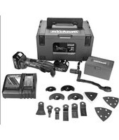
| Delivery contents | Multi-tool, accessories (sanding pad, segment blade, etc.), dust extraction adapter, hex key, carry bag, instruction manual |
| Usage | Cutting, sanding, scraping, sawing in wood, metal, plastic, putty, etc. |
| Maintenance | Regular cleaning of ventilation slots, lubrication of guide bushings |
| Warranty | 2 years (subject to conditions) |
| Spare parts | Available at authorized dealers |
Frequently Asked Questions - DTM51 MAKITA
User questions about DTM51 MAKITA
0 question about this device. Answer the ones you know or ask your own.
Ask a new question about this device
Download the instructions for your Multitools in PDF format for free! Find your manual DTM51 - MAKITA and take your electronic device back in hand. On this page are published all the documents necessary for the use of your device. DTM51 by MAKITA.
USER MANUAL DTM51 MAKITA
GB Cordless Multi Tool Instruction Manual
natural_image
Technical line drawing of a mechanical device with internal components (no text or symbols)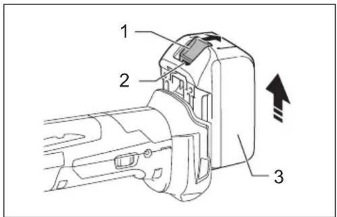
1

012128
3
0145564
5

014558

7
014555
014553_181113

natural_image
Line drawing of a mechanical device with a handle and spout, no text or symbols present9
01554_181113

11

natural_image
Line drawing of a handheld industrial vacuum cleaner with coiled tubing (no text or symbols)12

natural_image
Line drawing of a hand holding a handheld device against a wall (no text or symbols)13 14

natural_image
Line drawing of a hand using a power tool to clean or adjust a wooden block (no text or symbols)014561_181113
014559_181113 014560
Explanation of general view
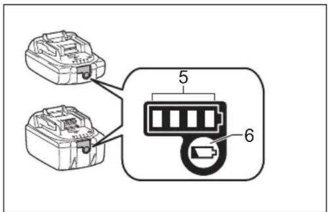
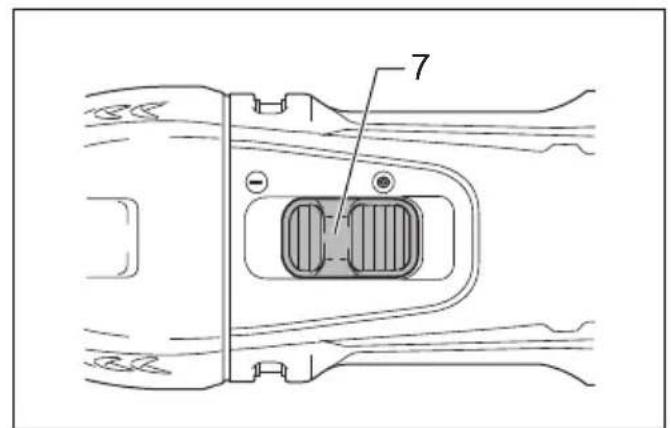
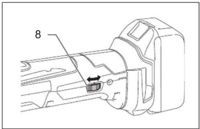
| 1 Button | 9 Indication lamp | 17 Dust attachment |
| 2 Red indicator | 10 Holder bolt | 18 Felt ring ( 37 mm) |
| 3 Battery cartridge | 11 Lock lever | 19 Pad (with OIS marking) |
| 4 Star marking | 12 Holes in the application tool | 20 Holes in the tool |
| 5 Indicator lamps | 13 Protrusions of the tool flange | 21 Protrusions on the nozzle band |
| 6 Check button | 14 Adapter | 22 Spacer |
| 7 Slide switch | 15 Nozzle band | 23 Felt ring ( 47 mm) |
| 8 Dial | 16 Dust nozzle | 24 Pad (with STARLOCK marking) |
SPECIFICATIONS
| Model | DTM51 |
| Oscillation per minute | 6,000 – 20,000 (min ^-1 ) |
| Oscillation angle, left/right | 1.6° (3.2° total) |
| Overall length | 326 – 340 mm |
| Net weight | 2.0 – 2.4 kg |
| Rated voltage | D.C. 18 V |
- Due to our continuing program of research and development, the specifications herein are subject to change without notice.
- Specifications may differ from country to country.
- The net weight value includes the lightest and heaviest combination of the attachment(s) for normal and safe use and battery cartridge(s) which are specified in the instruction manual.
Applicable battery cartridge and charger
| Battery cartridge | BL1815N / BL1820B / BL1830B / BL1840B / BL1850B / BL1860B |
| Charger | DC18RC / DC18RD / DC18RE / DC18SD / DC18SE / DC18SF / DC18SH / DC18WC |
- Some of the battery cartridges and chargers listed above may not be available depending on your region of residence.
WARNING: Only use the battery cartridges and chargers listed above. Use of any other battery cartridges and chargers may cause injury and/or fire.
ENE080-1
GEB094-2
Intended use
The tool is intended for sawing and cutting wood, plastic, gypsum, non-ferrous metals, and fastening elements (e.g. unhardened nails and staples). It is also intended for working soft wall tiles, as well as dry sanding and scraping of small surfaces. It is especially for working close to edge and flush cutting.
GEA010-2
General Power Tool Safety Warnings
WARNING Read all safety warnings, instructions, illustrations and specifications provided with this power tool. Failure to follow all instructions listed below may result in electric shock, fire and/or serious injury.
Save all warnings and instructions for future reference.
The term “power tool” in the warnings refers to your mains-operated (corded) power tool or battery-operated (cordless) power tool.
CORDLESS MULTI TOOL SAFETY WARNINGS
- This power tool is intended to function for sawing, cutting, grinding and sanding. Read all safety warnings, instructions, illustrations and specifications provided with this power tool. Failure to follow all instructions listed below may result in electric shock, fire and/or serious injury.
- Hold power tool by insulated gripping surfaces, when performing an operation where the cutting accessory may contact hidden wiring. Cutting accessory contacting a "live" wire may make exposed metal parts of the power tool "live" and could give the operator an electric shock.
- Use clamps or another practical way to secure and support the workpiece to a stable platform. Holding the work by hand or against your body leaves it unstable and may lead to loss of control.
- Always use safety glasses or goggles. Ordinary eye or sun glasses are NOT safety glasses.
- Avoid cutting nails. Inspect workpiece for any nails and remove them before operation.
-
Hold the tool firmly.
-
Make sure the application tool is not contacting the workpiece before the switch is turned on.
- Keep hands away from moving parts.
- Do not leave the tool running. Operate the tool only when hand-held.
- Always switch off and wait for the blade to come to a complete stop before removing the blade from the workpiece.
- Do not touch the application tool or the workpiece immediately after operation; they may be extremely hot and could burn your skin.
- Do not operate the tool at no-load unnecessarily.
- Always use the correct dust mask/respirator for the material and application you are working with.
- Some material contains chemicals which may be toxic. Take caution to prevent dust inhalation and skin contact. Follow material supplier safety data.
- This tool has not been waterproofed, so do not use water on the workpiece surface.
- Ventilate your work area adequately when you perform sanding operations.
- Use of this tool to sand some products, paints and wood could expose user to dust containing hazardous substances. Use appropriate respiratory protection.
- Be sure that there are no cracks or breakage on the pad before use. Cracks or breakage may cause a personal injury.
- Do not use accessories which are not specifically designed and recommended by the tool manufacturer. Just because the accessory can be attached to your power tool, it does not assure safe operation.
- Wear personal protective equipment. Depending on application, use face shield, safety goggles or safety glasses. As appropriate, wear hearing protectors, gloves and workshop apron capable of stopping small abrasive or workpiece fragments. The eye protection must be capable of stopping flying debris generated by various operations. The dust mask or respirator must be capable of filtrating particles generated by your operation. Prolonged exposure to high intensity noise may cause hearing loss.
- Keep bystanders a safe distance away from work area. Anyone entering the work area must wear personal protective equipment. Fragments of work-piece or of a broken accessory may fly away and cause injury beyond immediate area of operation.
- Never lay the power tool down until the accessory has come to a complete stop. The spinning accessory may grab the surface and pull the power tool out of your control.
- Do not run the power tool while carrying it at your side. Accidental contact with the accessory could snag your clothing, pulling the accessory into your body.
- Do not operate the power tool near flammable materials. Sparks could ignite these materials.
- Do not use accessories that require liquid coolants. Using water or other liquid coolants may result in electrocution or shock.
-
Always be sure that the tool is switched off and unplugged or that the battery cartridge is removed before carrying out any work on the tool.
-
Always be sure you have a firm footing. Be sure no one is below when using the tool in high locations.
SAVE THESE INSTRUCTIONS.
WARNING:
DO NOT let comfort or familiarity with product (gained from repeated use) replace strict adherence to safety rules for the subject product. MISUSE or failure to follow the safety rules stated in this instruction manual may cause serious personal injury.
ENC007-18
IMPORTANT SAFETY INSTRUCTIONS FOR BATTERY CARTRIDGE
- Before using battery cartridge, read all instructions and cautionary markings on (1) battery charger, (2) battery, and (3) product using battery.
- Do not disassemble or tamper with the battery cartridge. It may result in a fire, excessive heat, or explosion.
- If operating time has become excessively shorter, stop operating immediately. It may result in a risk of overheating, possible burns and even an explosion.
- If electrolyte gets into your eyes, rinse them out with clear water and seek medical attention right away. It may result in loss of your eyesight.
- Do not short the battery cartridge:
(1) Do not touch the terminals with any conductive material.
(2) Avoid storing battery cartridge in a container with other metal objects such as nails, coins, etc.
(3) Do not expose battery cartridge to water or rain.
A battery short can cause a large current flow, overheating, possible burns and even a breakdown. - Do not store and use the tool and battery cartridge in locations where the temperature may reach or exceed 50 °C (122 °F).
- Do not incinerate the battery cartridge even if it is severely damaged or is completely worn out. The battery cartridge can explode in a fire.
- Do not nail, cut, crush, throw, drop the battery cartridge, or hit against a hard object to the battery cartridge. Such conduct may result in a fire, excessive heat, or explosion.
- Do not use a damaged battery.
- The contained lithium-ion batteries are subject to the Dangerous Goods Legislation requirements. For commercial transports e.g. by third parties, forwarding agents, special requirement on packaging and labeling must be observed.
For preparation of the item being shipped, consulting an expert for hazardous material is required. Please also observe possibly more detailed national regulations.
Tape or mask off open contacts and pack up the battery in such a manner that it cannot move around in the packaging. -
When disposing the battery cartridge, remove it from the tool and dispose of it in a safe place. Follow your local regulations relating to disposal of battery.
-
Use the batteries only with the products specified by Makita. Installing the batteries to non-compliant products may result in a fire, excessive heat, explosion, or leak of electrolyte.
- If the tool is not used for a long period of time, the battery must be removed from the tool.
- During and after use, the battery cartridge may take on heat which can cause burns or low temperature burns. Pay attention to the handling of hot battery cartridges.
- Do not touch the terminal of the tool immediately after use as it may get hot enough to cause burns.
- Do not allow chips, dust, or soil stuck into the terminals, holes, and grooves of the battery cartridge. It may cause heating, catching fire, burst and malfunction of the tool or battery cartridge, resulting in burns or personal injury.
- Unless the tool supports the use near high-voltage electrical power lines, do not use the battery cartridge near high-voltage electrical power lines. It may result in a malfunction or breakdown of the tool or battery cartridge.
- Keep the battery away from children.
SAVE THESE INSTRUCTIONS.
CAUTION: Only use genuine Makita batteries.
Use of non-genuine Makita batteries, or batteries that have been altered, may result in the battery bursting causing fires, personal injury and damage. It will also void the Makita warranty for the Makita tool and charger.
NOTICE: Makita is not responsible for any accidents resulting from the use of non-genuine Makita batteries or batteries that have been modified. Genuine Makita batteries have been rigorously evaluated for compatibility with Makita tools and chargers, in line with applicable legislation and safety standards.
Tips for maintaining maximum battery life
- Charge the battery cartridge before completely discharged. Always stop tool operation and charge the battery cartridge when you notice less tool power.
- Never recharge a fully charged battery cartridge. Overcharging shortens the battery service life.
- Charge the battery cartridge with room temperature at 10 °C - 40 °C (50 °F - 104 °F). Let a hot battery cartridge cool down before charging it.
- When not using the battery cartridge, remove it from the tool or the charger.
- Charge the battery cartridge if you do not use it for a long period (more than six months).
FUNCTIONAL DESCRIPTION
WARNING:
• Always be sure that the tool is switched off and battery cartridge is removed before adjusting or checking function on the tool. Failure to switch off and remove the battery cartridge may result in serious personal injury from accidental start-up.
Installing or removing battery cartridge (Fig. 1)
CAUTION:
- Always switch off the tool before installing or removing of the battery cartridge.
- Hold the tool and the battery cartridge firmly when installing or removing battery cartridge. Failure to hold the tool and the battery cartridge firmly may cause them to slip off your hands and result in damage to the tool and battery cartridge and a personal injury.
To remove the battery cartridge, slide it from the tool while sliding the button on the front of the cartridge.
To install the battery cartridge, align the tongue on the battery cartridge with the groove in the housing and slip it into place. Insert it all the way until it locks in place with a little click. If you can see the red indicator on the upper side of the button, it is not locked completely.
CAUTION:
• Always install the battery cartridge fully until the red indicator cannot be seen. If not, it may accidentally fall out of the tool, causing injury to you or someone around you.
- Do not install the battery cartridge forcibly. If the cartridge does not slide in easily, it is not being inserted correctly.
Battery protection system (Lithium-ion battery with star marking) (Fig. 2)
Lithium-ion batteries with a star marking are equipped with a protection system. This system automatically cuts off power to the tool to extend battery life.
The tool will automatically stop during operation if the tool and/or battery are placed under one of the following conditions:
- Overloaded:
The tool is operated in a manner that causes it to draw an abnormally high current. In this situation, slide the slide switch on the tool toward the "O (OFF)" position and stop the application that caused the tool to become overloaded. Then slide the slide switch toward the "I (ON)" position again to restart. If the tool does not start, the battery is overheated. In this situation, let the battery cool before sliding the slide switch toward the "I (ON)" position again.
- Low battery voltage:
The remaining battery capacity is too low and the tool will not operate. In this situation, remove and recharge the battery.
Overheat protection
When the tool is overloaded and the tool temperature reaches a certain level, the tool automatically stops. In this situation, let the tool cool before turning on the tool again.
Indicating the remaining battery capacity (Fig. 3) Only for battery cartridges with the indicator
Press the check button on the battery cartridge to indicate the remaining battery capacity. The indicator lamps light up for few seconds.
| Indicator lamps | Remaining Capacity | ||
| Lighted Off | Blinking | ||
| 75% to 100% | |||
| 50% to 75% | |||
| 25% to 50% | |||
| 0% to 25% | |||
| Charge the battery. | |||
| The battery may have malfunctioned. | |||
015658
NOTE:
- Depending on the conditions of use and the ambient temperature, the indication may differ slightly from the actual capacity.
Switch action (Fig. 4)

CAUTION:
- Before installing the battery cartridge into the tool, always check to see that the tool is switched off.
To start the tool, slide the slide switch toward the "I (ON)" position.
To stop the tool, slide the slide switch toward the "O (OFF)" position.
Adjusting the orbital stroke rate (Fig. 5)
The orbital stroke rate is adjustable. To change the orbital stroke rate, turn the dial between 1 and 6. The higher the number is, the higher the orbital stroke rate is. Preset the dial to the number suitable for your workpiece.
NOTE:
- The dial cannot be turned directly from 1 to 6 or from 6 to 1. Forcing the dial may damage the tool. When changing the dial direction, always turn the dial moving it through each intermediate number.
Indication lamp (Fig. 6)
- When the remaining battery capacity gets low, the indication lamp blinks.
- When the remaining battery capacity gets much lower, the tool stops during operation and the indication lamp lights up about 10 seconds.
At this time, remove the battery cartridge from the tool and charge it.
ASSEMBLY

CAUTION:
- Always be sure that the tool is switched off and the battery cartridge is removed before carrying out any work on the tool.
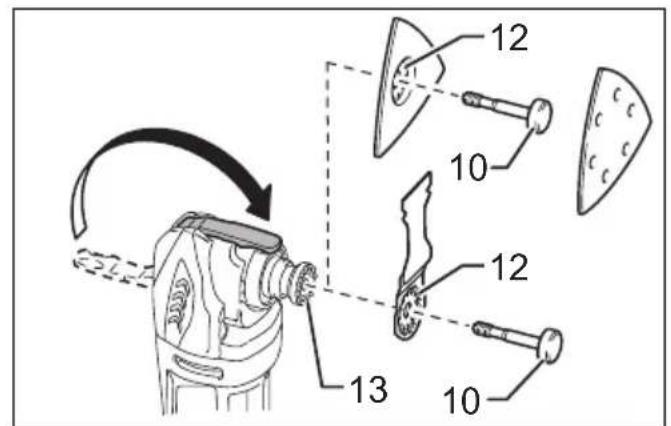
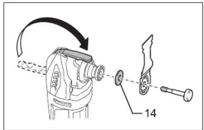
Installing or removing application tool (optional accessory) (Fig. 7, 8, 9 & 10)

WARNING:
- Do not install application tool upside down. Installing application tool upside down may damage the tool and cause serious personal injury.
- Install attachment tool in the correct direction according to your work. Application tool can be installed at an angle of every 30 degree.

CAUTION:
- Be careful when closing the lock lever. The lock lever may close suddenly and pinch your finger.
- Clean up dust and perform lubrication on the moving part of the lock lever from time to time. Otherwise dust may accumulate in the moving part of the lock lever and hinder its smooth movement.
-
Do not start the tool while the lever opens. The tool may be damaged.
-
Open the lock lever fully. And remove the holder bolt.
- Put an application tool (optional accessory) on the tool flange so that the protrusions of the tool flange fit in the holes in the application tool.
- Insert the holder bolt till it stops. And then, return the lock lever to its original position.
When using sanding application tool, mount the application tool on the sanding pad so that it matches the sanding pad direction.
The sanding pad has a hook and loop type fitting system which allows easy and rapid fitting of a sanding paper.
As sanding papers have holes for dust extraction, mount a sanding paper so that the holes in a sanding paper match those in the sanding pad.
To remove a sanding paper, raise its end and peel it off.
To remove the holder bolt, follow the installation procedures in reverse.
When using application tools with a different type of installation section, use a correct adapter (optional accessory).
Dust

WARNING:
- Depending on the material being worked on and the accessory used, the dust created by use of the tool can be harmful. The user is recommended to use an appropriate dust extractor to reduce exposure.
See the "OPTIONAL ACCESSORIES" section in this instruction manual for all optional dust extractor attachments available.
Additional Warnings:
- To prevent dust inhalation, it is recommended to also wear an FFP2 dust mask or P2 respirator.
- Read the “MAINTENANCE” section of the instruction manual of the connected dust extractor to keep the dust collection effective.
- Follow all applicable regulatory requirements for dust control in the country where the work is being conducted.
- Do not use a dust extractor for metalworking with power tools. Metal particles produced during metalworking can ignite accumulated dust and damage the dust filter inside dust extractors, posing a serious fire hazard.
- For European countries only The user is recommended to use an M or H dust class extractor (as defined in EN 60335-2-69).
For help and support regarding dust extractors, please contact your local Makita Service Center.
Dust extraction attachment (optional accessory) (Fig. 11 & 12)
• Install dust nozzles and dust attachment.
- Install the nozzle band on the tool so that its protrusions fit in the holes in the tool to secure it.
- Put the felt ring and the sanding pad on the dust attachment and then secure them with the application tool installation bolt.
When you wish to perform cleaner operation, connect a vacuum cleaner to your tool. Connect a hose of vacuum cleaner to the dust extraction attachment (optional accessory).
Use the front cuff 22 to connect the hose.
The inner diameter of the dust nozzle for the hose connection is 26 mm.
OPERATION

WARNING:
- Before starting the tool and during operation, keep your hand and face away from the application tool.

CAUTION:
- Do not apply excessive load to the tool which may cause a motor lock and stop the tool.
Cutting, sawing and scraping (Fig. 13)

CAUTION:
- Do not move on the tool forcibly in the direction (eg. towards either side) of tool application with no cutting edge. It may damage the tool.
Put the application tool on the workpiece.
And then move the tool forward so that the application tool movement does not slow down.
NOTE:
- Forcing or excessive pressure on the tool may reduce efficiency.
- Before cutting operation, it is recommended to preset the orbital stroke rate 4 – 6.
- Remove sawdust by drawing the tool adequately. It increases work efficiency.
- The round saw is recommended for cutting long straight line.
Sanding (Fig. 14)

CAUTION:
- Do not reuse a sanding paper used for sanding metal to sand wood.
- Do not use a worn sanding paper or sanding paper without grit.
Apply a sanding paper on the workpiece.
NOTE:
- Using a test material sample to try is recommendable to determine a correct orbital stroke rate suitable for your work.
- Use a sanding paper with the same grit until sanding the whole workpiece is completed. Replacing a sanding paper with different grit sanding paper may not get a fine finish.
MAINTENANCE

CAUTION:
- Always be sure that the tool is switched off and the battery cartridge is removed before attempting to perform inspection or maintenance.
- Never use gasoline, benzine, thinner, alcohol or the like. Discoloration, deformation or cracks may result.
To maintain product SAFETY and RELIABILITY, repairs, carbon brush inspection and replacement, any other maintenance or adjustment should be performed by Makita Authorized Service Centers, always using Makita replacement parts.
OPTIONAL ACCESSORIES

CAUTION:
• These accessories or attachments are recommended for use with your Makita tool specified in this manual. The use of any other accessories or attachments might present a risk of injury to persons. Only use accessory or attachment for its stated purpose.
If you need any assistance for more details regarding these accessories, ask your local Makita Service Center.
- Segment saw blade
- Round saw blade
- Plunge cut saw blade
- Scraper (rigid)
- Scraper (flexible)
- Serrated seg blade
- General joint cutter
- HM remover
• HM seg saw blade - HM sanding plate
• Diamond seg sawblade - Sanding pad
- Adapter
- Abrasive paper delta (red / white / black)
• Fleece delta (medium / coarse / without grit) - Polishing felt delta
- Hex wrench
• Dust extraction attachment - Makita genuine battery and charger
NOTE:
- Some items in the list may be included in the tool package as standard accessories. They may differ from country to country.
ENG905-1
Noise
The typical A-weighted noise level determined according to EN62841-2-4:
Work mode: Sanding Sound pressure level ( L_pA ): 80 dB (A) Sound power level ( L_WA ): 88 dB (A) Uncertainty (K): 3 dB (A)
The typical A-weighted noise level determined according to EN62841-1:
Work mode: Cutting with plunge cut saw blade Sound pressure level ( L_pA ): 84 dB (A) Sound power level ( L_WA ): 92 dB (A) Uncertainty (K): 3 dB (A)
The typical A-weighted noise level determined according to EN62841-1:
Work mode: Cutting with segmental saw blade Sound pressure level ( L_pA ): 79 dB (A) Uncertainty (K): 3 dB (A)
The noise level under working may exceed 80 dB (A).
The typical A-weighted noise level determined according to EN62841-1:
Work mode: Scraping
Sound pressure level ( L_pA ): 83 dB (A)
Sound power level (LWA): 91 dB (A)
Uncertainty (K): 3 dB (Å)
NOTE:
- The declared noise emission value(s) has been measured in accordance with a standard test method and may be used for comparing one tool with another.
- The declared noise emission value(s) can also be used in a preliminary assessment of exposure.

WARNING:
- Wear ear protection.
- The noise emission during actual use of the power tool can differ from the declared total value(s) depending on the ways in which the tool is used.
- Be sure to identify safety measures to protect the operator that are based on an estimation of exposure in the actual conditions of use (taking account of all parts of the operating cycle such as the times when the tool is switched off and when it is running idle in addition to the trigger time).
Vibration
The continuous vibration total value (tri-axial vector sum) determined according to EN62841-2-4:
Work mode: sanding
Vibration emission ( a_h ): 3.0 m/s ^2
Uncertainty (K): 1.5 m/s ^4
The continuous vibration total value (tri-axial vector sum) determined according to EN62841-1:
Work mode: cutting with plunge cut saw blade
Vibration emission ( a_h ): 7.0 m/s ^2
Uncertainty (K): 1.5 m/s²
The continuous vibration total value (tri-axial vector sum) determined according to EN62841-1:
Work mode: cutting with segment saw blade
Vibration emission (a _h ): 4.5 m/s ^2
Uncertainty (K): 1.5 m/s ^4
The continuous vibration total value (tri-axial vector sum) determined according to EN62841-1:
Work mode: scraping
Vibration emission (ah): 5.5 m/s²
Uncertainty (K): 1.5 m/s²
NOTE:
- The declared vibration total value(s) has been measured in accordance with a standard test method and may be used for comparing one tool with another.
- The declared vibration total value(s) can also be used in a preliminary assessment of exposure.

WARNING:
- The vibration emission during actual use of the power tool can differ from the declared total value(s) depending on the ways in which the tool is used.
- Be sure to identify safety measures to protect the operator that are based on an estimation of exposure in the actual conditions of use (taking account of all parts of the operating cycle such as the times when the tool is switched off and when it is running idle in addition to the trigger time).
The following shows the mean values of the peak amplitude of the acceleration from repeated shock vibrations, p_F , with corresponding uncertainty (K) determined according to EN62841-2-4.
Work mode: sanding
p_F : 195 m/s²
Uncertainty (K): 22 m/s ^4
The following shows the mean values of the peak amplitude of the acceleration from repeated shock vibrations, p_F , with corresponding uncertainty (K) determined according to EN62841-1.
Work mode : cutting with plunge cut saw blade
p_F : 490 m/s²
Uncertainty (K): 100 m/s²
The following shows the mean values of the peak amplitude of the acceleration from repeated shock vibrations, p_F , with corresponding uncertainty (K) determined according to EN62841-1.
Work mode : cutting with segment saw blade
p_F : 325 m/s²
Uncertainty (K): 124 m/s²
The following shows the mean values of the peak amplitude of the acceleration from repeated shock vibrations, p_F , with corresponding uncertainty (K) determined according to EN62841-1.
Work mode : scraping
p_F : 301 m/s²
Uncertainty (K): 8 m/s²
NOTE:
- These declared values should not be used to determine hand arm vibration exposure.
DECLARATIONS OF CONFORMITY
For European countries only
The EU Declaration of Conformity can be accessed from the following URL.

https://support.makita.biz/doc/doc_index.html
For the UK
The Declaration of conformity is included in Annex A to this instruction manual.
Descriptif
DÉCLARATIONS DE CONFORMITÉ
OPTIONELE ACCESSOIRES
LET OP:


- Intended use
- General Power Tool Safety Warnings
- Save all warnings and instructions for future reference.
- CORDLESS MULTI TOOL SAFETY WARNINGS
- SAVE THESE INSTRUCTIONS.
- WARNING:
- IMPORTANT SAFETY INSTRUCTIONS FOR BATTERY CARTRIDGE
- CAUTION: Only use genuine Makita batteries.
- Tips for maintaining maximum battery life
- FUNCTIONAL DESCRIPTION
- Installing or removing battery cartridge (Fig. 1)
- CAUTION:
- Battery protection system (Lithium-ion battery with star marking) (Fig. 2)
- Overheat protection
- Indicating the remaining battery capacity (Fig. 3) Only for battery cartridges with the indicator
- NOTE:
- Switch action (Fig. 4)
- Adjusting the orbital stroke rate (Fig. 5)
- Indication lamp (Fig. 6)
- ASSEMBLY
- Installing or removing application tool (optional accessory) (Fig. 7, 8, 9 & 10)
- Dust
- Additional Warnings:
- Dust extraction attachment (optional accessory) (Fig. 11 & 12)
- OPERATION
- Cutting, sawing and scraping (Fig. 13)
- Sanding (Fig. 14)
- MAINTENANCE
- OPTIONAL ACCESSORIES
- Noise
- Vibration
- DECLARATIONS OF CONFORMITY
- For European countries only
- For the UK
- DÉCLARATIONS DE CONFORMITÉ
- OPTIONELE ACCESSOIRES
- LET OP:
Brand : MAKITA
Model : DTM51
Category : Multitools