
UAP-LR - Access Point Ubiquiti Networks - Free user manual and instructions
Find the device manual for free UAP-LR Ubiquiti Networks in PDF.


| Product Type | Access Point |
| Brand | Ubiquiti Networks |
| Model | UAP-LR (Long Range) |
| Dimensions | 20 x 20 x 3.65 cm |
| Weight | 290 g (430 g with mounting kits) |
| Network Interface | Ethernet (Auto MDX, autosensing 10/100 Mbps) |
| Antennas | 2 Integrated (2x2 MIMO with spatial diversity) |
| Wi-Fi Standards | 802.11 b/g/n (2.4 GHz) |
| Maximum TX Power | 27 dBm |
| Maximum Power Consumption | 6W |
| Power Method | Passive Power over Ethernet (12-24V) |
| Included Power Supply | 24V 0.5A PoE Adapter |
| Security | WEP, WPA-PSK, WPA-TKIP, WPA2 AES, 802.11i |
| Mounting | Wall/Ceiling (kits included) |
| Operating Temperature | -10 to 70°C (14 to 158°F) |
| Operating Humidity | 5 - 80% Condensing |
| Number of BSSID | Up to four per radio |
| Concurrent Clients | 100+ |
| Advanced Features | VLAN 802.1Q, per-user rate limiting, guest traffic isolation, WMM |
| Supported Data Rates | Up to 300 Mbps (802.11n HT20/40) |
| Certifications | CE, FCC, IC |
| Included Accessories | PoE adapter, power cord, mounting hardware, CD with software, quick start guide |
| System Requirements | Windows XP/Vista/7, Mac OS X, Java Runtime 1.6+, Web browser (Firefox, Chrome, IE8+) |
| Management Software | UniFi Controller (browser-based interface) |
| Care and Cleaning | Gently wipe with a dry cloth; avoid liquids and abrasive cleaners. Keep away from water. |
| Safety | Use only provided power cord; avoid electrical storms; do not submerge in water; professional installation recommended. |
| Spare Parts | No user-serviceable parts; contact Ubiquiti Networks support for replacements. |
| Repairability | Not intended for user repair; service must be performed by qualified technician. |
Frequently Asked Questions - UAP-LR Ubiquiti Networks
User questions about UAP-LR Ubiquiti Networks
0 question about this device. Answer the ones you know or ask your own.
Ask a new question about this device
Download the instructions for your Access Point in PDF format for free! Find your manual UAP-LR - Ubiquiti Networks and take your electronic device back in hand. On this page are published all the documents necessary for the use of your device. UAP-LR by Ubiquiti Networks.
USER MANUAL UAP-LR Ubiquiti Networks
Table of Contents
Chapter 1: Product Overview ....1
Package Contents....1
System Requirements....1
Network Topology Requirements....1
Front....2
Back....2
Chapter 2: Installation ....3
Hardware Installation....3
Software Installation....5
Chapter 3: Using the UniFi Controller Software....7
Interface Tabs 7
Common Interface Options....7
Recent Events 7
Settings....8
Admin 12
Chapter 4: Map Tab....13
Adding Custom Maps....13
Adding a Google Map TM ..... 14
Placing Access Points on the Map....16
Setting the Map Scale 18
Chapter 5: Statistics Tab ....20
Clients 20
Quick Look....20
Current Usage - Top Access Points 21
Recent Activities....21
Chapter 6: Access Points Tab....22
Chapter 7: Users Tab....23
Chapter 8: Guests Tab 24
Chapter 9: Offline Clients Tab .... 25
Chapter 10: Access Point Details....26
Details 26
Users 27
Guests 28
Configuration 28
Chapter 11: User/Guest Details ...... 34
Details 34
Statistics 34
History 35
Configuration 35
Chapter 12: HotSpot Manager....36
Appendix A: Portal Customization....38
Overview....38
Enabling Portal Customization....38
Viewing the Default Portal 38
Setup 38
Appendix B: UniFi Discovery Utility 40
Overview....40
Appendix C: Specifications 42
Appendix D: Safety Notices....44
Electrical Safety Information 44
Appendix E: Warranty 45
General Warranty....45
Appendix F: Compliance Information 46
Installer Compliance Responsibility 46
FCC....46
Industry Canada....46
RF Exposure Warning....46
CE Marking....46
RoHS/WEEE Compliance Statement....46
Appendix G: Declaration of Conformity....48
Appendix H: Contact Information....49
Ubiquiti Networks Support 49
Chapter 1: Product Overview
Thank you for purchasing the Ubiquiti UniFi Enterprise WiFi System. The UniFi Enterprise WiFi System includes the UniFi Controller software that allows you to manage your wireless network using your Web browser.
This User Guide is for use with version 2.0 or above of the UniFi Controller software with the following UniFi Enterprise WiFi System Access Point models:
| Model | Maximum Power Consumption | Maximum TX Power |
| UniFi AP (UAP) | 4W 20 dBm | |
| UniFi AP Long Range (UAP-LR) | 6W 27 dBm |
Unless otherwise needed to specify differences between the two models, this Quick Start Guide will refer to both as UniFi AP.
The UniFi Enterprise WiFi System also includes the necessary hardware for mounting the unit on a wall or a ceiling. The UniFi Enterprise WiFi System supports Passive PoE which works with the included PoE adapter. If you want to power the UniFi AP from an 802.3af compliant switch, Ubiquiti Networks offers the optional Instant 802.3af Adapter to instantly transform any PoE device into a fully 48V 802.3af compliant product. Product details are available on our website at http://ubnt.com/8023af
Package Contents
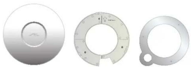
UniFi AP Wall-Mount Bracket Ceiling-Mount Plate
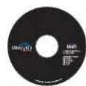
UniFi Controller
CD with User Guide
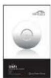
Quick Start Guide

24v PoE Adapter

Power Cord

M3X30 Flat Head Screw (Qty. 3)

M3 Keps Nut with Tooth Washer (Qty. 3)

M2.9x20 Self Tapping Screw (Qty. 3)
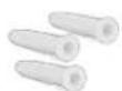
M3x20 Screw Anchor (Qty. 3)
System Requirements
- Microsoft Windows XP, Windows Vista, Windows 7, or Mac OS X
• Java Runtime Environment 1.6 (or above) - Web Browser: Mozilla Firefox, Google Chrome, or Microsoft Internet Explorer 8 (or above)
Network Topology Requirements
- A DHCP-enabled network (for the wired Access Point to obtain an IP address as well as for the wireless Access Points after the deployment).
- Access Point(s) and either an on-site management station computer running the UniFi Controller software connected to the same Layer-2 network or located in an off-site cloud or NOC.
![graph TD A["On-Site Management Station"] --> B["Router"] C["Off-Site Cloud/NOC²"] --> B D["Wired UAP/UAP-LR"] --> B E["Wireless Uplinked¹ UAP/UAP-LR"] --> B B --> F["Controller icons"] style B fill:#f9f,stroke:#333](/content/2026/06/1266160/images/311d0c53b933b488ea8272a5b779836f6f50bafcccf9708f234f3a49d811caac.jpg)
Sample Network Topology
Please refer to "Wireless Uplinks" on page 31 for setting up Wireless-Linked APs.
2 All UniFi APs support Off-Site Management Controllers.
Front

LED Indicates the status of the device. See the table below for details.
| LED Color Status | |
| Flashing Amber Initializing | |
| Steady Amber Factory default, waiting to be integrated | |
| Alternating Amber/Green | Device is busy, do not touch or unplug it, this usually indicates a process such as a firmware upgrade is taking place |
| Quickly Flashing Green | This is used to locate an AP.When you click onLocatein the UniFi Controller software, the AP will blink. It will also display the location of the AP on the map. |
| Steady Green | Indicates the device has been successfully integrated into a network and is working properly. |
| Steady Green with occasional flashing | Indicates the device is in an isolated state (all WLANS are brought down until an uplink is found). |
Back
Reset Button The reset button serves two functions:
- Restart It will restart the device when you press and release it quickly.
- Restore Factory Defaults When you press and hold it for more then 5 seconds, it will restore the device to the factory default settings.

Ethernet Port Connects to the 24v PoE Adapter to provide power to the unit.
Chapter 2: Installation
Hardware Installation
The UniFi Enterprise WiFi System is powered by the included PoE (Power over Ethernet) adapter. To install the AP, perform the following steps:
- Connect an Ethernet cable to the Ethernet port on the UniFi Enterprise WiFi System.
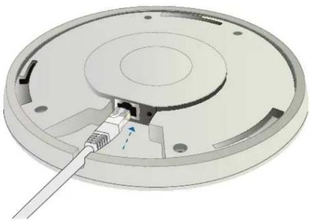
- Connect the power cord to the power port on the PoE Adapter. Connect the other end to of the power cord to a power outlet.

- Connect the other end of the Ethernet cable to the Ethernet port labeled PoE on the PoE Adapter.

Note: If you plan to mount the AP on your ceiling, perform the ceiling mount installation steps before connecting the Ethernet cable to the PoE Adapter.

Below is an overview of the Power over Ethernet connections.

Power Connection Diagram
Mounting the Access Point
The UniFi Enterprise WiFi System can be wall-mounted or mounted on a ceiling. Perform the following steps for the appropriate installation:
Wall-Mount
- Align the wall-mounting bracket with the Wall Mount text facing up. There are horizontal and vertical lines on the bracket to help with orientation.

- Use a pencil to mark the holes on the wall.
- Use a 6 mm drill bit to drill the holes in the wall.
- Insert the 3 screw anchors into the wall.
- Secure the wall-mount bracket to the wall by inserting the self tapping screws into the anchors.

- Align the notches on the AP with the notches on the wall-mount bracket.

- Turn the AP clockwise until it locks into place.

Ceiling-Mount
- Remove the ceiling tile.
- Align the ceiling-mount plate to the center of the top side of the ceiling tile.
- Use a 3.5 mm drill bit to drill holes for the three flat head screws.
-
Cut or drill a circle approximately 25 mm in size that lines up with the larger circle on the ceiling-mount plate. This will be used for the Ethernet cabling.
-
Secure the wall-mount bracket and ceiling-mount plate to the ceiling tile using the 3 flathead screws and 3 nuts with tooth washers.

- Feed the Ethernet cable through the hole and then align the UniFi AP with the notches on the wall-mount bracket.
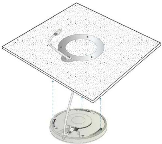

Note: The UniFi AP supports Passive PoE which works with the included PoE adapter. If you want to power the UniFi AP from an 802.3af compliant switch, Ubiquiti Networks offers the optional Instant 802.3af Adapter to instantly transform any PoE device into a fully 48V 802.3af compliant product. Product details are available on our website at http://ubnt.com/8023af
- Turn the AP clockwise until it locks into place.
Software Installation
Insert the UniFi Controller software CD into your CD-ROM drive and follow the instructions for your specific computer type.
Mac Users
- Click on the Install icon.

- Click Continue and follow the on-screen instructions to install the software.

- Go to Go > Applications and double-click the UniFi icon.
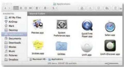
Proceed to "Configuring the UniFi Controller Software" on page 6.
PC Users
-
Launch UniFi-installer.exe.
-
Click Install.
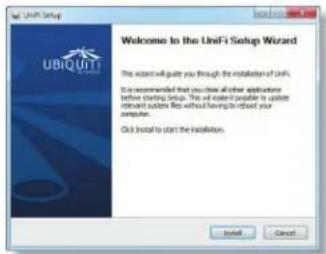
- If your computer doesn't have Java 1.6 or above installed, you will be prompted to install it. Click Install to continue.

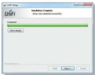
- Click Next.
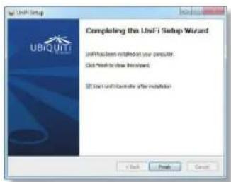
- Be sure the Start UniFi Controller after installation option is checked and click Finish.

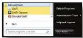
Note: The UniFi Controller software can also be launched from Start > All Programs > Ubiquiti UniFi.
Configuring the UniFi Controller Software
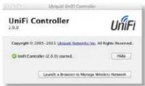
- The UniFi Controller software startup will begin. When the option becomes available, click Launch a Browser to Manage Wireless Network.
- Select your language and country. Alternatively you can restore from a previous backup by clicking Browse. Click Next.

- Select the devices that you want to configure and click Next.

- The UniFi Installation Wizard will create a secure primary wireless network for your devices. Perform the following steps:

a. Enter a unique wireless network name (SSID) in the Secure SSID field.
b. Enter a unique passphrase to be used for your primary network in the Security Key field.
c. To enable guest access, select Enable Guest Access and enter a guest network name in the Guest SSID field.
d. Click Next.
- Enter an admin name in the Admin Name field and password in the Password field to use when accessing the management interface. Confirm your password in the Confirm field. Click Next.

- On the Finish tab, review your settings. Click Back to make changes or Finish to save your settings. Once finished you will be redirected to the management interface via your web browser.
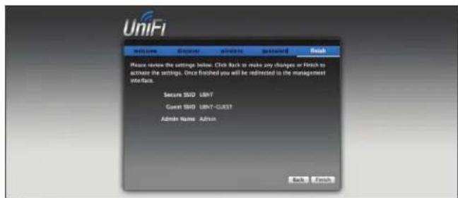
Congratulations, your wireless network is now configured.
A login screen will appear for the UniFi Controller management interface. Enter the admin name and password that you created and click Login.

Proceed to the next chapter for information on using the UniFi Controller software.
Chapter 3: Using the UniFi Controller Software
The UniFi Controller software that comes with your UniFi Enterprise WiFi System has a browser-based interface for easy configuration and management.
To access the interface, perform the following steps:
- Launch the UniFi Controller application if hasn't already been started.
• Mac users: Go > Applications > UniFi - Windows users: Start > All Programs > Ubiquiti UniFi.
- The UniFi login screen will appear. Enter the admin name and password in the appropriate fields and click Login.

Interface Tabs
The UniFi software consists of six primary tabs. This User Guide covers each tab with a chapter. For details, on a specific tab, refer to the appropriate chapter.
• "Map Tab" on page 13
• "Statistics Tab" on page 20
- "Access Points Tab" on page 22
• "Users Tab" on page 23
• "Guests Tab" on page 24
• "Offline Clients Tab" on page 25
Common Interface Options
The common interface options are accessible from all tabs in the UniFi interface.

Access Points
- connected Drop-down clickable list of all of the Access Points that are online.
- disconnected Displays a list of Access Points that were previously online but are no longer accessible.
- pending Drop-down clickable list of all of the Access Points that are not yet managed but are available for management.
Stations
- users Displays the total number of users connected to the primary network.
- guests Displays the total number of users connected to the guest network.
Recent Events
Displays a list of recent events including the date and time the event occurred and the details of the event. The User and Access Point names are clickable links.
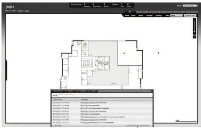
Event Slider Move the slider right and left to navigate between pages of events.
Search Allows you to enter text you want to search for. Simply begin typing, there is no need to press Enter.
Clicking on an Event Device Link
The event messages have clickable links [in brackets underlined in gray text] for AP (See "Access Point Details" on page 26), User and Guest (See "User/Guest Details" on page 34). Details vary based on the selection.
Alerts
Important events are displayed in the alerts window. The date and time of the event and the message are displayed.

Search Allows you to enter text you want to search for. Simply begin typing, there is no need to press enter.
Show Archived Show all of the alert messages that have been archived.
Archive All Archive all of the alert messages displayed on the screen.
Adopt Click to adopt an Access Point that is waiting for adoption.
Archive Archive the selected alert message.
Settings


System System related settings.

Guest Control Guest portal and policies.

Wireless Networks Wireless networks.

Blocked Devices List of blocked wireless devices.

Admin Settings Admin username, password and preferences.

User Groups User Group settings.
Settings > System
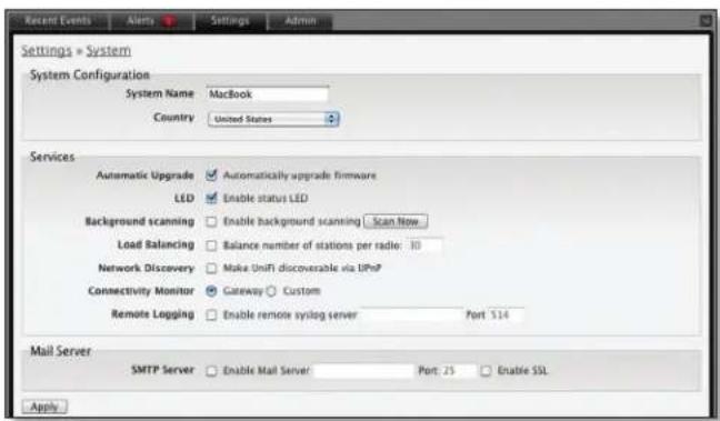
System Configuration
System Name Editable field with the system name.
Country Select your country from the drop-down list.
Services
Automatic Upgrade When enabled, this option will automatically upgrade your firmware when an update is available.
LED When enabled, this option will illuminate the LED on the Access Point. When disabled, this option will turn off the LED on the Access Point.
Background Scanning When enabled, all managed Access Points will scan in the background for "Rogue Access Points"- third party Access Points or UniFi Access Points that are being managed by another instance of the UniFi Controller software. This option is disabled by default.
- Scan Now When clicked, all managed Access Points will scan for a 2-3 second period across all maps for Access Points. New Access Points in their default state will appear under Access Points > Pending. Additionally, Background Scanning will automatically detect Access Points that have been disconnected and attempt to reconnect them.
Load Balancing Sets a desired number of clients per AP. While an AP will allow more clients to connect, it will start to look at those with lower signals and disconnect them.
Network Discovery When enabled, this option allows UniFi to be discoverable via UPnP. This option is disabled by default.
Connectivity Monitor When enabled, all managed Access Points will use the Gateway of the Access Point that is providing IP information either by DHCP or Static designation. By selecting Custom, an alternate Uplink IP address can be specified. Gateway is selected by default.
Remote Logging Enable to define a remote syslog server. Enter the IP address and port of the syslog server.
Be sure to click Apply to save any changes that you have made.
Mail Server
When enabled, UniFi will send email alerts when triggered (Pending Access Points and Disconnected Access Points) to the administrator email address specified under Settings > Admin Settings > Admin Preferences > Email Alert.

SMTP Server Enable by selecting the check box and entering the outgoing (SMTP) mail server name. Optionally, you may enable Secure Sockets Layer (SSL) to provide communication security over the Internet. The port number will automatically change to 465.
Enable authentication Enable by selecting the check box and entering the username and password required by the mail server.
Test SMTP Server Enter an email address and click Send to test the mail server setup.
Apply Click Apply to save changes.
Settings > Guest Control

Guest Policies
Guest Portal This option is disabled by default. When disabled, guests can access the Internet without entering a password or accepting Terms of Use. When this option is enabled, you can control the Guest Portal.
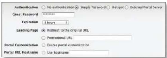
Authentication When the Guest Portal is enabled, the authentication options will appear. There are four different authentication methods available:
Authentication ☐ No authentication ○ Simple Password ○ Hotspot ○ External Portal Server
- No authentication When this option is selected, guests are not required to log in, but must accept the Terms of Use. When selecting No authentication, Guest Policy must be selected under Settings > Wireless Networks > SSID > Edit > Wireless Configurations in order to enforce selection of the Terms of Use by the guest.

- Simple Password When this option is selected, guests are required to enter the simple password and accept the Terms of Use. When selecting Simple Password, Guest Policy must be selected under Settings > Wireless Networks > SSID > Edit > Wireless Configurations in order to enforce entry of the password and selection of the Terms of Use by the guest.
- Hotspot When selected, enables Hotspot functionality including the ability to customize portal login pages and bill customers using major credit cards or via PayPal™. When selecting Hotspot, Hotspot > Voucher and/or Hotspot > Payment must be selected as a method of Hotspot authorization. Also, Guest Policy must be selected under Settings > Wireless Networks > SSID > Edit > Wireless Configurations in order to enforce entry of voucher, payment and Terms of Use by the guest.

- External Portal Server If using an external server to host a custom guest portal, enter the IP address in the Custom Portal > IP Address box using the following format: 192.168.0.0.
Authentication ○ No authentication ○ Simple Password ○ Hotspot ● External Portal Server Custom Portal IP Address
- Guest Password (Option only visible when using Simple Password authentication) Enter a password that guests must enter before accepting the Terms of Use and connecting to the Internet.
- Expiration (Option only visible when using No authentication or Simple Password authentication) Allows the specification of guest login expiration after a designated period of time. Options include: 8 hours, 24 hours, 2 days, 3 days, 4 days, 7 days and User-defined. User defined can be designated in minutes, hours and days.
- Custom Portal (Option only visible when using External Portal Server authentication) Enter the IP address using the following format: 192.168.0.0.
- Landing Page The landing page is the page where guests are redirected after accepting the terms of use. There are two options available:
- Redirect to the original URL When this option is selected, guests are directed to the URL they requested after accepting the Terms of Use.
- Promotional URL When this option is selected, guests are redirected to the URL that you specify here after accepting the Terms of Use. Be sure to specify the URL with http:// in front of the web address. Example: http://www.ubnt.com
- Portal Customization When enabled, allows customized portal pages to appear in place of default login pages. See "Portal Customization" on page 38 for details on setting up custom portal pages.
- Portal URL Hostname Allows the designation of a hostname for the portal URL in place of the default IP address. Paired with a SSL certificate, ensures site certificates are displayed as trusted in the guest browser. Example: www.ubnt.com
Hotspot
The Hotspot options are only visible when Hotspot authentication is selected.
- Voucher When selected, vouchers (including distributable code, duration values, and use restrictions) can be created using Hotspot Manager (see "HotSpot Manager" on page 36).
-
Payment When enabled, allows payment-based authentication to be set up with your PayPal Website Payments Pro account. Payment and Transctions can be managed using Hotspot Manager (see "HotSpot Manager" on page 36).
• PayPal PayPal account details are entered here: -
Username Enter the corresponding Username.
- Password Enter the corresponding Password
- Signature Enter the corresponding Signature for the PayPal account to be used for receiving payments.
- Use Paypal Sandbox For PayPal testing purposes, enable this option and click Apply Sandbox Account to set up/access your PayPal Sandbox Test Environment.
- Hotspot Operator Click Go to Hotspot Manager to manage Wireless Guests, Payments/Transactions, Vouchers, and Operator Accounts. See "HotSpot Manager" on page 36.
- Apply Click Apply to save changes.
When logging in with No authentication, guests will be required to accept the Terms of Use before gaining access to the Internet.

When logging in with Simple Password authentication, guests will be required to enter the Guest Password and accept the Terms of Use before gaining access to the Internet.

When logging in with Voucher-based Hotspot authentication, guests will be required to enter the voucher number and accept the Terms of Use before gaining access to the Internet.

When logging in with Payment-based Hotspot authentication, guests will be required to select package type, payment choice and accept the Terms of Use before gaining access to the Internet.

Access Control
Restricted Subnets Enter in any subnets that you don't want guests to be able to access.
Apply Click Apply to save changes.
Settings > Admin Settings

Admin Name Displays the current admin name used to login. To change the admin name, simply enter a new name and click Apply.
Password A new password can be entered in this field. Be sure to enter the password again in the Confirm field and then click Apply to save your new password.
Confirm Used to confirm your new password.
Language Selects the language for use in the interface.
Email Alert Select to enable email alerts and enter the administrator email address in the Send alert to email box. See "Mail Server" on page 9 for information on setting up the outgoing (SMTP) mail server.
Apply Click Apply to save changes.
Settings > Wireless Networks
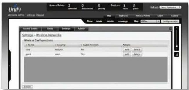
Wireless Configurations
Name Displays the wireless network name (SSID).
Security Displays the type of security being used on your wireless network.
Guest Network Indicates whether the network is a guest network.
Actions Select an action button to perform the desired action:
Edit Select to make changes to the wireless network settings.
Delete Select to delete the wireless network.
Wireless Configuration

-
Name/SSID Allows you to edit the wireless network name (SSID).
• Security Selects the type of security to use on your wireless network. -
Open This option is typically only used on the Guest network. When enabled, wireless network access is open to anyone without needing a password.
- WEP WEP (Wired Equivalent Privacy) is the oldest and least secure security algorithm. WPA security methods should be used when possible.
- WEP Key Enter a WEP encryption key in hexadecimal format. You can enter a 64-bit or 128-bit key:
| Type HEX | |
| 64-bit 10 | Hexadecimal Characters (0-9, A-F or a-f)Example:00112233AA |
| 128-bit 26 | Hexadecimal Characters (0-9, A-F or a-f)Example:00112233445566778899AABBCC |
• Key Index Specifies the Index of the WEP Key used. 4 different WEP keys can be configured at the same time, but only one is used. The effective key is set by choosing 1, 2, 3 or 4.
- WPA-Personal WPA™ or Wi-Fi Protected Access was developed as a stronger encryption method over WEP. WPA-Personal requires a passphrase to connect to the wireless network.
• Security Key Enter the passphrase that users will use to connect to the wireless network.
- WPA-Enterprise WPA Enterprise uses a RADIUS server to authenticate users on the wireless network.
- IP Address This is where the IP address of the RADIUS server is specified.
- Port The port number is entered here. By default it is 1812.
- Password The password used to authenticate on the RADIUS server is entered here.
- Guest Policy Select this option to enable guest access policies on this wireless network.
Advanced
- VLAN To use a VLAN, select Use VLAN ID and enter the port number.
- Hide SSID Select this option if you don't want the SSID to be broadcast.
• WPA Defines supported WPA and encryption methods. - User Group Allows assignment of wireless users to a specific user group.
Be sure to click Apply to save any changes that you have made. Click Cancel to discard changes.
Settings > Blocked Devices
Displays the list of blocked wireless devices.

Unblock Click to unblock a wireless device. See "User/Guest Details" on page 34 for information on blocking wireless devices.
Settings > User Groups

Create Click to create a new user group.

- Name Enter a descriptive user group name.
- Bandwidth Limit (Download) When selected, allows the designation of a download bandwidth limit in Kbps.
- Bandwidth Limit (Upload) When selected, allows the designation of a upload bandwidth limit in Kbps.
- Create Click to create user group.
- Cancel Click to cancel user group creation.
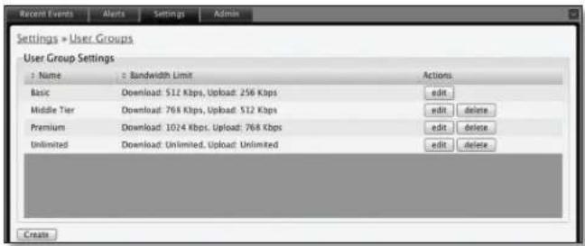
Edit Click to change the name or bandwidth settings of the user group.
Delete Click to delete the user group.
See "Configuration" on page 35 for information on the application of User Groups to Users/Guests.
Admin

The Admin tab displays server version information, allows system backups to be created and downloaded, allows system restoration from backup files and allows configuration information to be downloaded to assist in support issues.
Server Information
Version The software version is displayed here. If there is an update, UniFi will automatically download it and display it here.
Backup
Download Backup Settings Click to download a file that contains all of your settings so you can restore them later if you choose.
Restore
Choose File Select this option to restore settings from a backup file that you've already downloaded.
Support Info
Download Support Info Select this option to download a file to your computer with information about your configuration that can be emailed to our support team.

Chapter 4: Map Tab
The UniFi Controller software allows you to upload custom map images of your location(s) or use Google Maps™ for a visual representation of your wireless network. When you initially launch the UniFi Controller application, a default map is displayed.
Adding Custom Maps

To add a custom map, you must first create the image using an illustration, image editing, or blueprint application that exports .jpg, .gif, or .png file formats.
Once you've created the map, you can upload it to the UniFi Controller software by performing the following steps:
- Click Configure Maps.
Configure Maps button

- Click Add a Map.

- Enter a map name in the Description field and click Upload my own. Click the Browse button to locate the file to use as a map (valid file formats are .jpg, .gif, and .png). Click Continue.

- Click Close.

Adding a Google Map™
To add a Google Map™ into the UniFi Controller software Map view:
- Click Configure Maps.

- Click Add a Map.
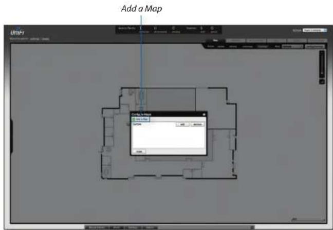
- Enter a map name in the Description field and click Use Google Maps. Click Continue.

- In order to use a Google Map™, you must register with Google for a Google Maps API key. To do so, click Specify API Key.
![Configuration Map from Design Map Unlabeled In-Load Design Map [ ] [ ] [ ]](/content/2026/06/1266160/images/218cfd348cc655d8d683050afe15329c07f73e21b7cb12a0e31ff626df782a41.jpg)
- Click or copy and paste the web link from the window into a new web browser window. Do not close the UniFi window.
http://code.google.com/apis/maps/signup.html

- You need to be signed in with a Google account to obtain a Google Maps API key.
- Review the terms and conditions and click the checkbox next to I have read and agree with the terms and conditions.
- Navigate back to the UniFi window and copy the address that UniFi displays in the address bar.

Note: You only need to copy until the end of the address, do not include the port information. In the example below, the full address is https://192.168.25.191:8443/manage#. You only need to copy up to https://192.168.25.191. Do not include the colon or anything beyond it.
- Navigate back to the Google Maps API Family window and paste the address into the My web site URL: box.
-
Click the Generate API Key button.
-
A new window will open displaying your key. Highlight and copy the Google Maps API key.
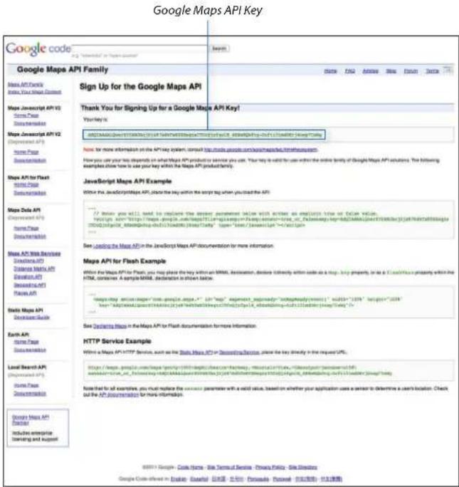
- Navigate back to the UniFi window and paste the API Key into the API Key field. Click continue.
- The default Google Map location will appear. Click the Set Location button in the lower left.

- Select Specify Address to enter an address. Type in the address and then click Go. You also have the Specify Coordinates option to enter the latitude and longitude of a specific location.

- The specified location should appear. Click Save.

- Click Close.
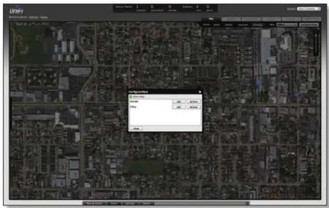
- You can adjust the zoom using the slider on the right.
Placing Access Points on the Map
- Drag the Access Point icon(s) from the Unplaced APs list on the left to the appropriate location(s) on the map.

The access point will appear in the area that you placed it.
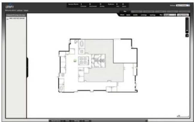

Wired/Wireless Access Point Shows the location of the Access Point on the map.
Click and hold this icon to drag the Access Point to another location on the map. Click on the Access Point icon to reveal additional options. Click a blank area of the map to hide them.

Lock Locks the selected Access Point in the current location on the map.

Details Brings up the Details window. This allows you to view Access Point settings and connected users. You can also edit the radio channel, transmit power, uplink and device alias.

There are 4 tabs to select from in the Details window. Details, Users, Guests, and Configuration.
- Details Displays details on the Access Point including the MAC address, model, version, IP address, uptime, connected users, and connected guests. Click Uplink (Wire) to display the speed, duplex, Down Pkts / Bytes, Up Pkts / Bytes and Activity. Click Radio to display the channel used, transmit power, and packet information.
- Users Displays the hostname of the users that are connected to the selected Access Point and the IP address assigned to them.
You can click on the hostname to display additional details of each user. A window with Details, Statistics, and Configuration is displayed. The Details tab displays the MAC address, hostname, IP address, uptime and the Access Point they are connected to. The Statistics tab displays the channel used, signal strength, transmit and receive rates, power saving enabled or disabled, and the number of packets sent and received. You can also click History to see a sortable list of events. The Configuration tab allows you to change the alias name for the device.
• Guests Displays the MAC address of guests that are connected to the guest network.
- Configuration Allows you to change the alias name of the device, the channel setting, and set the transmit power to Auto, High, Medium, Low or Custom. You can also remove the Access Point if you no longer want to manage it with the UniFi Controller software.

Remove Remove the Access Point from the location on the map.
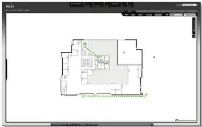
Show: You can click each of the following options to display Access Point labels, details, wireless coverage and topology on the map.

- Labels Displays the name applied to the Access Point. Refer to Alias under "Configuration" on page 28 to change a name applied to an Access Point. If no custom label is applied, the Access Point's MAC address will be displayed.

- Details Displays the Access Point name, MAC address, transmit/receive channel, number of users connected, and number of guests connected.

• Coverage Displays a visual representation of the wireless range covered by the Access Point.

Topology Displays a visual representation of the network configuration and connections between Access Points. Devices that are wirelessly connected will have a wireless icon next to them. A path of arrows will indicate which device the wireless device is downlinking from.
Map: If multiple maps have been uploaded, you can select which map you want to view using this option.

Configure Maps Use this option to add maps or edit the current map(s).
Zoom Slider Use to zoom the map detail in and out.

Set Map Scale Use this option to define the scale of the map. You will draw a line and define the distance that the line represents.
Setting the Map Scale
- Click the Set Map Scale button.
- Click and hold to draw a line in the area that you want to use to set the scale of the map. If you need to redraw the line, just click and hold again to draw a new line. Once you're happy with the line, click Next.

- Enter the distance that the line represents in the Distance: field. The distance is specified in meters by default but you can switch to feet using the drop-down selection menu on the right. Click Next.


Chapter 5: Statistics Tab
The Statistics tab provides a visual representation of the network traffic connected to your managed APs. Charts representing the number of clients and network traffic are displayed. An hour by hour chart of the usage over the last 24 hours is also displayed on this screen.

Clients
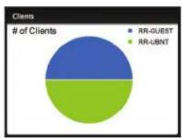
# of Clients Displays a visual pie chart representation of the client distribution. Place the mouse cursor over the chart for percentage details.
Quick Look

Most Active AP Displays the most active Access Point details including the name or MAC address of the Access Point, the total amount of data sent and the total amount of data received.
The name or MAC address of the Access Point is a clickable link that will open the device details page. See "Access Point Details" on page 26 for additional information.
Most Active Client Displays the details of the most active currently connected client. The name or MAC address of the client device, the total amount of data sent and the total amount of data received is displayed here.
The name or MAC address of the client device is a clickable link that will open the device details page. See "User/Guest Details" on page 34 for additional information.
All-Time Top Client Displays the details of the all-time most active client. The name or MAC address of the client device, the total amount of data sent and the total amount of data received is displayed here.
The name or MAC address of the client device is a clickable link that will open the device details page. See "User/Guest Details" on page 34 for additional information.
Current Usage - Top Access Points

# of Clients Displays a visual pie chart representation of the client distribution on the most active Access Points. Place the mouse cursor over the chart for percentage details.
Traffic Displays a visual pie chart representation of traffic on the most active Access Points. Place the mouse cursor over the chart for percentage details.
Recent Activities

The Recent Activities statistics can be toggled between a view for the last 24 hours and also for the last 30 days.
# of Clients Displays a visual graph of the number of clients connected during the selected time period (last 24 hours or last 30 days).
Traffic Displays a visual graph of the network traffic during the selected time period (last 24 hours or last 30 days).

Chapter 6: Access Points Tab
The Access Points tab displays a list of managed Access Points with their name, IP address, status, number of clients connected, download/upload statistics, and their transmit/receive channel.
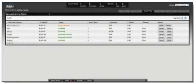
Search Allows you to enter text you want to search for. Simply begin typing, there is no need to press Enter. Page Size Allows you to determine how many results are displayed per page. Select 10, 20, 30, 40, 60, or 100.
Name/MAC Address Displays the hostname, alias, or MAC address of the Access Point. You can click on the name to get additional details on the Access Point.
IP Address Displays the IP address of the Access Point.
Status Displays the connection status information.
- Connected Displays that the Access Point connection is physically wired.
- Connected (wireless) Displays that the Access Point connection is wirelessly downlinked to a physically wired Access Point.
- Disconnected Displays if the Access Point is unreachable by the UniFi Controller software. Disconnected Access Points will also appear under Access Points > Disconnected at the top of the interface.
- Isolated A managed Access Point that is unable to locate its uplink.
Num Clients Displays the number of clients connected to the Access Point.
Download Displays the total size of downloads via the Access Point.
Upload Displays the total size of uploads via the Access Point.
Channel Displays the transmit/receive channel being used by the Access Point.
Actions Select an action button to perform the desired action:
- Restart Restart the selected Access Point.
- Locate Click to Locate the Access Point on the map. The button will flash green and black until the Locate button is clicked again. The LED on the Access Point will flash so that you can place it in the correct location on the map. The LED will flash until the Locate button is clicked again.
- Adopt Click to adopt an Access Point that appears under Access Points > Pending at the top of the interface. The Status will appear as Adopting until the Access Point is connected.

- Upgrade If a software upgrade is available for the Access Point, click Upgrade to install the latest UniFi firmware on the device. The Status will appear as Upgrading until the process is complete and the Access Points reconnects to the UniFi Controller software.


Chapter 7: Users Tab
The Users tab displays a list of users that are connected to the primary wireless network of the Access Point.

Search Allows you to enter text you want to search for. Simply begin typing, there is no need to press Enter.
Filter by AP Drop-down list of all available Access Points. Select one to filter the results and display only users connected to the selected Access Point.
Page Size Allows you to determine how many results are displayed per page. Select 10, 20, 30, 40, 60, or 100.
Name/MAC Address Displays the hostname, alias, or MAC address of the connected user. You can click on the name to get additional details.
IP Address Displays the IP address assigned to the user.
WLAN Displays the name of the SSID (network name) of the wireless LAN (WLAN) that the user is connected to.
Access Point Displays the hostname or alias of the Access Point. You can click on the name to get additional details on the Access Point.
Signal Displays the signal strength and type (b/g/n) from the Access Point to the client. If a lightning bolt symbol is present, the device is in power save mode. The device will return to active mode when Down or Up activity resumes.
Down Displays the total bytes of data received by the user.
Up Displays the total bytes of data sent by the user.
Activity Displays the level of activity for each user.
| Bars | Activity Level (Bytes per second) |
| Idle | |
| 500 | |
| 8000 | |
| 64000 | |
| 512000 | |
| 2048000 |
Uptime Displays the total time the user has been connected for this session.
Actions Click an action button to perform the appropriate action.
- Block Click this to block a specific user from accessing the Access Point. This will add the client to the Blocked Device list.
- Reconnect Click this button to reconnect a specific user to the Access Point.

Chapter 8: Guests Tab
The Guests tab displays a list of users that have connected to the guest network of the Access Point.
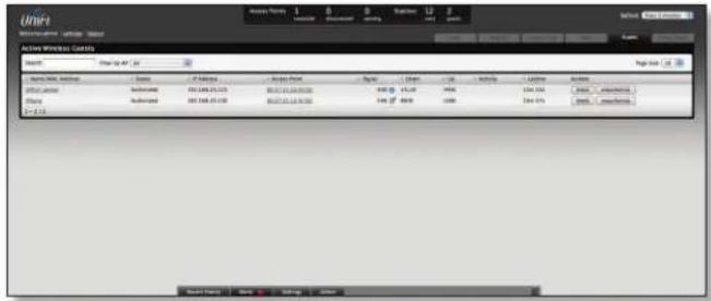
Search Allows you to enter text you want to search for. Simply begin typing, there is no need to press Enter.
Filter by AP Drop-down list of all available Access Points. Select one to filter the results and display only guests connected to the selected Access Point.
Page Size Allows you to determine how many results are displayed per page. Select 10, 20, 30, 40, 60, or 100.
Name/MAC Address Displays the hostname, alias, or MAC address of the connected guest. You can click on the name to get additional details.
Status Indicates whether the guest is authorized or not. For authorization, guests must accept the Terms of Use if the guest portal is enabled and authenticate if authentication is enabled.
IP Address Displays the IP address assigned to the guest.
Access Point Displays the hostname or alias of the Access Point. You can click on the name to get additional details on the Access Point.
Signal Displays the signal strength and type (b/g/n) from the Access Point to the client. If a lightning bolt symbol is present, the device is in power save mode. The device will return to active mode when Down or Up activity resumes.
Down Displays the total bytes of data received by the guest.
Up Displays the total bytes of data sent by the guest.
Activity Displays the level of activity for each guest.
| Bars | Activity Level (Bytes per second) |
| Idle | |
| 500 | |
| 8000 | |
| 64000 | |
| 512000 | |
| 2048000 |
Uptime Displays the total time the user has been connected for this session.
Actions Click an action button to perform the appropriate action.
- Block Click this to block a specific guest from accessing the Access Point.
- Reconnect Click this button to reconnect a specific guest to the Access Point.
• Authorize When a guest is in a pending state, authorization can be granted here manually. - Unauthorize Removes authorization of wireless guest access and disconnects the client.

Chapter 9: Offline Clients Tab
The Offline Clients tab displays a list of users that have connected to the guest or primary network of the Access Point at some time during the period specified.

Search Allows you to enter text you want to search for. Simply begin typing, there is no need to press Enter.
- Users Select if you only want users displayed.
• Guests Select if you only want guests displayed.
• All Select to show all users and guests.
Last Seen Drop-down list that allows you to filter the results on the page based on the time the user was last seen. Select 1 day, 3 days, 7 days, 2 weeks, 1 month, 2 months, or 1 year.
Page Size Allows you to determine how many results are displayed per page. Select 10, 20, 30, 40, 60, or 100.
Name/MAC Address Displays the hostname, alias, or MAC address of the connected guest. You can click on the name to get additional details.
User/Guest Indicates whether the user is connected to the primary or guest network.
Down Displays the total bytes of data received by the user.
Up Displays the total bytes of data sent by the user.
Actions Click an action button to perform the appropriate action.
- Block Click this to block a specific guest from accessing the Access Point.
Chapter 10: Access Point Details
UniFi Access Points connect to the UniFi Controller software either by Ethernet, denoted as Connected or by a wireless connection, denoted as Connected (wireless). Based on connection type, options under each tab vary. The upper part of the window has 4 clickable tabs. The bottom of the window has a Locate and Restart button. Use the Locate button to flash the LED on the Access Point and flash the Access Point icon on the map. Use the Restart button to restart the Access Point. The 4 tabs include: Details, Users, Guests, and Configuration.
Details
Displays details about the Access Point. Click Overview to display the device specifics, connection details, uptime and user statistics.
Overview

MAC address Displays the MAC address of the Access Point.
Model Displays the model information.
Version Displays the version of software used on the Access Point.
IP address Displays the IP address of the Access Point.
Uptime Displays the amount of time the Access Point has been running without interruption.
# Users Displays the number of users connected to the primary network.
# Guests Displays the number of users connected to the guest network.
Uplink (Wireless)
Displays details on a wirelessly-connected Access Point including the Uplink Access Point (by specified name or MAC address), signal strength to the Uplink Access Point, TX Rate, RX Rate, Down Pkts / Bytes, Up Pkts / Bytes and Activity. See "Wireless Uplinks" on page 31 to find, select and connect to a wireless Access Point.

Uplink (Wire)
Displays details on a wired Access Point including the connection speed, duplex type, Down Pkts / Bytes in K/M, Up Pkts / Bytes in K/M and Activity in B/sec.

Downlinks
Displays which wireless Access Points are currently connected to the wired Access Point. Includes details such as the downlink Access Point (by specified name or MAC address), signal strength and the option to remove the wireless Access Point from the wired Access Point by clicking Remove.


Note: Downlinks will only be visible under the Details tab when a wireless Access Point is connected.
Radio (11n/b/g)
Click Radio (11n/b/g) to display the channel and transmit/receive statistics.

Channel Displays the wireless channel being used.
Transmit Power Displays the EIRP in dBm.

Note: If the device has an external antenna, you can mouseover for additional details.
TX Pkts / Bytes Displays the number of packets and total bytes transmitted by the Access Point.
RX Pkts / Bytes Displays the number of packets and total bytes received by the Access Point.
TX Retry / Dropped Displays the percentage of transmitted packets that needed to be resent and the percentage of packets that were dropped.
RX Error / Dropped Displays the percentage of packets received that needed to be resent and the percentage of packets that were dropped.
# Users Displays the number of users connected to the primary network.
# Guests Displays the number of users connected to the guest network.
Users
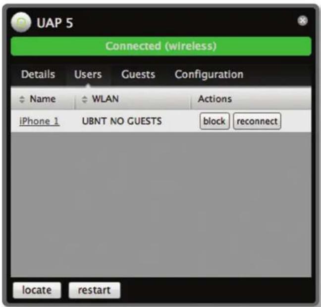
Name Displays the name (MAC address if not defined) of users connected to the primary network of the selected Access Point. You can click the links under Name to display additional details of each user (see "User/Guest Details" on page 34 for more information).
WLAN Displays the name of the SSID (network name) of the wireless LAN (WLAN) that the user is connected to.
Actions Select from one of the following actions:
- Block Click this to block a specific user from accessing the Access Point. This will add the client to the Blocked Device list.
- Reconnect Click this button to reconnect a specific user to the Access Point.
Guests

Name Displays the name (MAC address if not defined) of users connected to the guest network of the selected Access Point. You can click on the name to display additional details of each user (see User below) or click a button to perform the appropriate action.
WLAN Displays the name of the SSID (network name) of the wireless LAN (WLAN) that the user is connected to.
Actions Select from one of the following actions:
- Block Click this to block a specific user from accessing the Access Point. This will add the client to the Blocked Device list.
- Reconnect Click this button to reconnect a specific user to the Access Point.
Configuration
Allows you to change device configuration settings. Be sure to click the Apply button to commit any changes.
Config
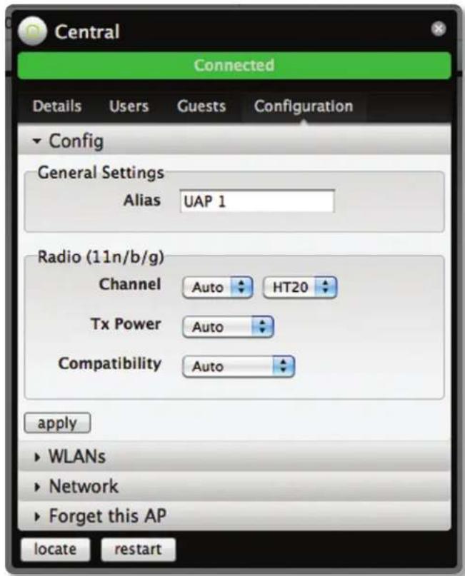
General Settings
Alias Allows you to name the device.
Radio (11n/b/g)
Channel Select a channel or leave the default auto setting. You can also use the default HT20 for 20 MHz operation or HT40 for 40 MHz operation.
Tx Power By default the transmit power is set to Auto. You can also manually select High, Medium, Low or Custom.
• High The highest TX power we can deliver.
- Low The lowest TX power.
• Medium Halfway in between High and Low.
- Custom Full custom setting. If the AP is using an external antenna, the Antenna Gain field will appear allowing you to specify the gain of the attached antenna. After applying the settings, go to Transmit Power under Detail > Radio (11/n/g/b), which always shows EIRP, mouseover it to display how it's calculated
Compatibility Selects the wireless compatibility mode. By default this is set to auto. Choose one of the following:
• Auto Supports wireless b/g/n standards.
- 11n/11g only Only supports wireless-n and wireless-g devices.
• 11n only Only supports wireless-n devices.
• 11g only Only supports wireless-g devices.
WLANs
Allows the deployment of different WLANs on different Acess Points.
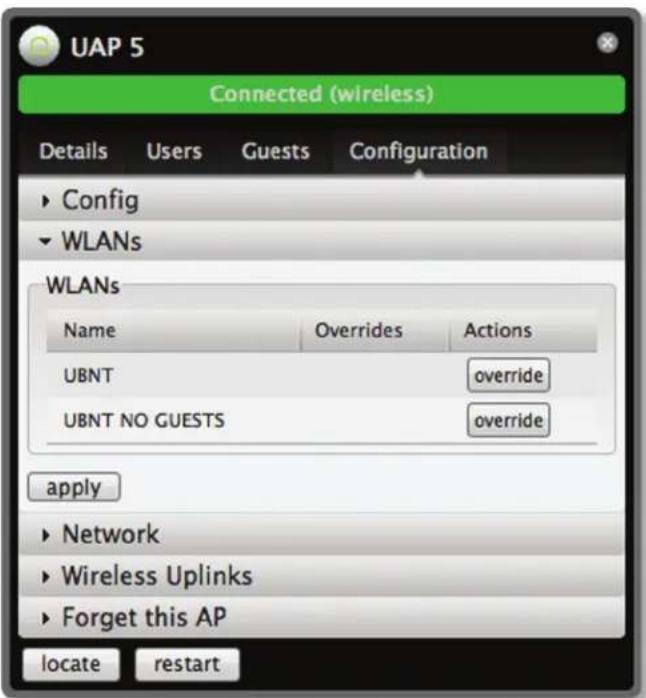
Name Displays the name of the SSID (network name) of the wireless LAN (WLAN) that is available for the user to connect to.
Overrides Displays SSID override information applied to the wireless LAN (WLAN) using the Actions > Override option.
Actions Click Override to enable a VLAN, set the VLAN ID and enter the SSID override name to apply to the wireless LAN (WLAN).

Enabled Select to enable or clear to disable override settings on the WLAN.
VLAN Select to enable VLAN or clear to disable VLAN.
VLAN ID The VLAN ID is a unique value assigned to each VLAN at a single device; every VLAN ID represents a different Virtual Network. A value between 2 and 4095 may be entered. For example, in a larger deployment where there are multiple buildings, it's possible that a different VLAN ID is used in each building while still on the same corporate network.
SSID Enter the SSID override name to apply to the wireless LAN (WLAN).
PSK If the WPA-Personal security option has been applied to the WLAN under Settings > Wireless Networks, the Pre-Shared Key (PSK) for the SSID specified will automatically appear in this field.
Be sure to click Apply to save any changes that you have made. Click Restore to remove any overrides that were applied to the selected WLAN. Click Cancel to prevent application of any changes you have made.
Network
The Access Point can be configured to obtain an IP address automatically or configured with a static IP address.
Network Settings
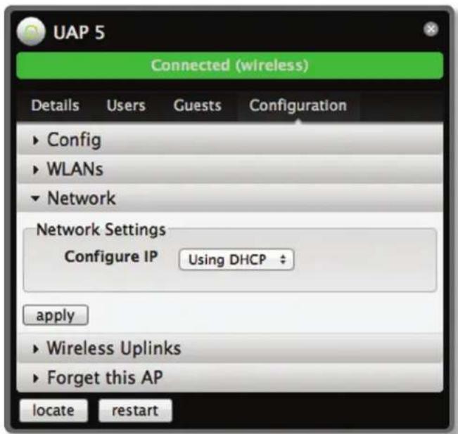
Configure IP Select between Using DHCP or Static IP:
- Using DHCP Choose this option to obtain the IP address, Gateway and DNS address dynamically from the external DHCP server.
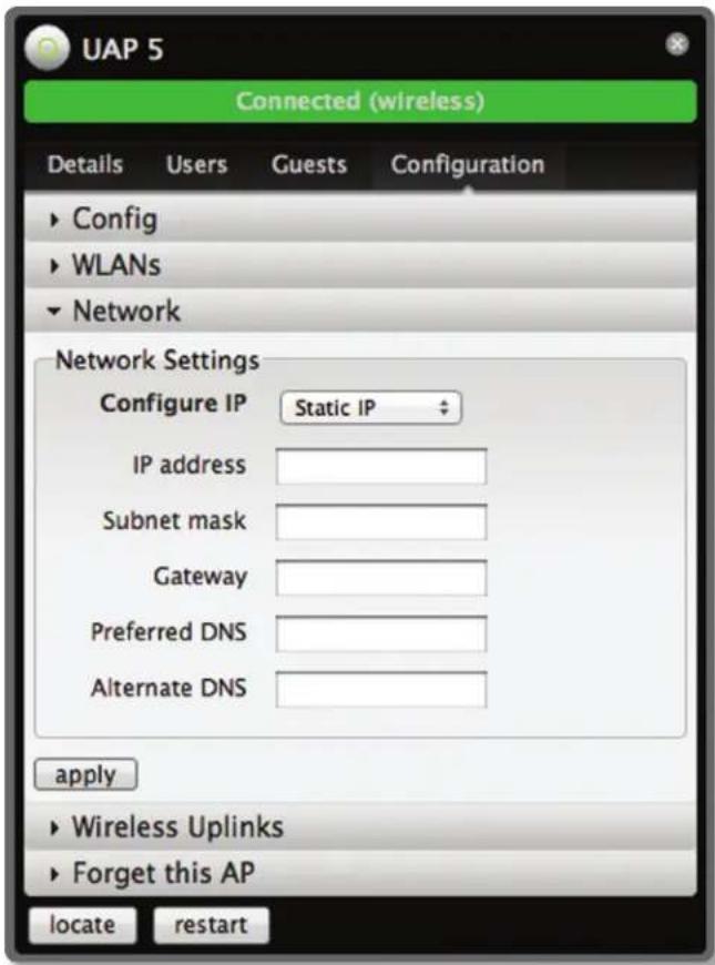
- Static IP Choose this option to assign the static IP address settings, Subnet mask, Gateway, Preferred DNS and Alternate DNS for the Access Point.
- IP address Enter the IP address for the Access Point.
- Subnet mask Enter the subnet mask for the Access Point.
- Gateway Enter the gateway address.
- Preferred DNS Enter a primary DNS address.
- Alternate DNS Enter a secondary DNS address.
Apply Click apply to save any changes that you have made.
Wireless Uplinks
When an Access Point is not connected by a wire, Wireless Uplinks lists potential uplink Access Points that can be selected to establish a wireless connection.

- AP Displays the specified name (or MAC address) of the potential Uplink Access Point.
- Channel Displays the channel being used for wireless communication.
• Signal Displays the signal level. - Actions
- Remove Click Remove to disconnect the wireless Access Point from the wired Access Point.
- Select Click Select to connect to the wireless Access Point to the wired Access Point.
- Find More Click to manually instruct the Access Point to search for any available potential uplinks. The search can be conducted across all locations (maps) or a single location can be selected from the drop-down menu.
Access Point - Heartbeat Missed
When a wired Access Point is disconnected from the router, it's state will initially change to Heartbeat Missed, followed by Isolated.

Access Point - Isolated
When an Access Point is in an Isolated state, a connection to the UniFi Controller software can be reestablished by reconnecting the Access Point to the router or by establishing a wireless uplink to a wired Access Point. See "Wireless Uplinks" on page 31 to find, select and connect to a wireless Access Point.


Note: When in an Isolated state, the Access Point icon will change to red/orange on the Map tab.

The LED on the actual device will be steady green with occasional flashing. This Access Point doesn't provide any wireless service.

Note: Do not use the Forget this AP option when the Access Point is in an Isolated state. If you do, the only way to make the Access Point accessible from the UniFi Controller is to take it down and connect by wire.
Access Point - Managed by Other
When an Access Point is in Managed by Other state, this indicates that the Access Point is not in the default state but it is not controlled by the UniFi Controller.
Overview

MAC address Displays the MAC address of the Access Point.
Model Displays the model information.
Version Displays the version of software used on the Access Point.
Last Seen Displays the amount of time that has passed since the Access Point was last seen.
Advanced Adoption

IP The IP address and SSH port of the Access Point are populated here.
Username Enter the SSH Username for management access.
Password Enter the SSH Password for management access.
Inform URL The URL will be populated but you may need to verify the accuracy as the system may have multiple interfaces.
Forget this AP

Forget Click to remove the Access Point from management by the UniFi Controller software and to restore it to factory default settings.

Note: Use caution when clicking Forget. This will restore the Access Point to factory settings when in a Connected state. Do not use the Forget option when the Access Point is in an Isolated state. If you do, the only way to make the Access Point accessible from the UniFi Controller is to take it down and connect by wire.
Chapter 11: User/Guest Details
The User and Guest hyperlinks bring up the User/Guest Details window. There are 4 clickable tabs at the top of the window and two buttons located on the bottom of the window. The buttons are accessible from any of the tabs and perform the following actions:
Block The block button allows you to block the selected user from accessing the network.
Reconnect Allows you to reconnect a user that has been blocked previously.
The 4 tabs contain the following information:
Details
Overview

MAC address Displays the MAC address of the Access Point.
Hostname Displays the name (if defined).
IP address Displays the IP address of the Access Point.
Uptime Displays the amount of time the Access Point has been running without interruption.
Connected AP Displays the name or MAC address of the Access Point this user is connected to.
Statistics
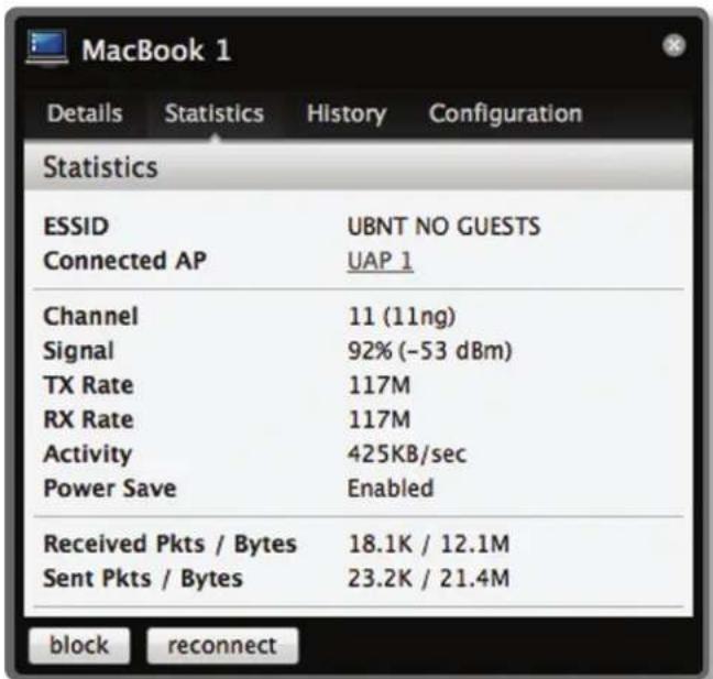
ESSID Displays the wireless network name (SSID) of the network that the user is connected to.
Connected AP Displays the MAC address or name of the Access Point the user is connected to.
Channel Displays the channel being used for wireless communication.
Signal Displays the signal level.
TX Rate Displays the transmit rate.
RX Rate Displays the reception rate.
Activity Displays user activity.
Power Save Indicates whether power saving is enabled.
Received Pkts / Bytes Displays the number of packets and total bytes transmitted by the user.
Sent Pkts / Bytes Displays the number of packets and total bytes received by the user.

Note: The Statistics tab will only appear when the User/Guest is connected.
History

Date/Time Displays the date and the time the user connected to the Access Point.
Duration Displays the time duration that the user was connected to the Access Point.
Down Displays how many bytes were downloaded by the user during the session.
Up Displays how many bytes were uploaded by the user during the session.
Configuration
Config

Alias Allows you to enter a name for the user. Be sure to click Apply to save your name change.
Usergroups Allows you to select the User Group to assign to the User/Guest. User Groups are set up under the Settings tab > User Groups option (see "Settings > User Groups" on page 12) for information on setting up User Groups.
Debug
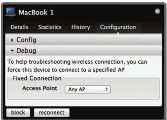
Debug Allows you to force a device to connect to a specific Access Point.

Chapter 12: HotSpot Manager
Hotspot Manager includes 4 main tabs when accessed by the UniFi Controller admin account. These tabs include Wireless Guests, Payments/Transactions, Vouchers and Operator Accounts.
Operator accounts that are created by the admin will have access to 3 tabs when they login. These tabs include Wireless Guests, Payments/Transactions, and Vouchers tabs.
Wireless Guests
Lists the Hotspot's currently active wireless guests. Includes keyword Search box and Show guests within drop-down selections (options include last 24 hours, 3 days, 7 days, 2 weeks, 30 days and 120 days).

Name/MAC Address Displays the connected guest's device name or MAC address.
Package Displays the type of package that was purchased (if applicable).
Amount Displays amount paid for access (if applicable).
Authorized By Displays authorization method or none.
Download Displays the total number of bytes downloaded by the guest.
Upload Displays the total number of bytes uploaded by the guest.
Status Displays the remaining session time for the guest.
Actions
- Disconnect Allows you to immediately disconnect a guest.
- Extend Allows you to extend a guests session for an additional 24 hours every time you click this button. If you click it three times, you will extend the guest access for 3 more days.
Payments/Transactions
Lists the Hotspots payments and transactions. Includes keyword Search box and Show guests within drop-down selections (options include last 24 hours, 3 days, 7 days, 2 weeks, 30 days and 120 days).

Time Displays the time and date of the transaction.
Last Name Displays the user's last name.
First Name Displays the user's first name.
Package Displays the package description.
Amount Displays the amount of the transaction.
Extra Info If the user paid via PayPal, the Extra Info field displays the email address associated with the PayPal account. If the user paid via credit card, the Extra Info field will display the type of credit card and the last 4 digits of the credit card used.
Status Displays the status of the transaction.
Actions Allows you to refund a customer if necessary by clicking the Refund button.
Vouchers
Allows the creation of vouchers including a distributable code, duration values, and use restrictions.
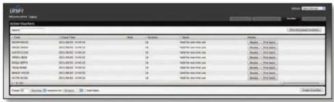
Search Enter keywords in the Search box to find a specific voucher based on Code, Create Time or Note values.
Print all Unused Vouchers Click Print All Unused Vouchers to send a page to your printer with voucher code and validity details.
Code Displays a list of active voucher codes.
Create Time Displays the time and date the voucher was created.
Note Displays any notes that were added using the Add Notes option during voucher creation.
Duration Displays the duration of minutes, hours, or days that the voucher enables the user to access the Internet.
Status Indicates whether it is a single-use or multi-use voucher.
Actions
- Revoke Immediately deactivates the selected voucher.
• Print Batch Prints the selected voucher.
Active Voucher Page Slider Adjust the slider from left to right to view all Active Vouchers.
Create Vouchers Includes box to specify number of vouchers to create, a drop-down selector to choose whether the voucher can be used One-time or for Multi-use and how long the voucher is valid (options include 8 hours, 24 hours, 2 days, 3 days, 4 days, 7 days or User-defined).
- Add Notes Select to add a note specific to the batch of vouchers created.
Click Create Vouchers to create the vouchers as specified.
Operator Accounts
Allows the creation of Operator Accounts that can log in to Hotspot Manager to manage wireless guests, payments/transactions, and vouchers.

- Search Enter keywords in the Search box to find a specific operator account based on Name, Password or Notes values.
- Actions Click Delete to remove an operator.
- Account Enter a name for the operator. The Account can only be A-Z, a-z, or 0-9. No spaces are allowed.
- Password Enter a password for the operator. The Password has to start with A-Z, a-z, or 0-9 and the others can only be printable ASCII characters
- Note If desired, enter a note to identify or describe the operator.
- Create Operator Click Create Operator to create the operator account as specified. To test the operator account, log out of the UniFi Controller software and log in using the operator credentials. Only the Wireless Guests, Payments/Transactions and Vouchers tabs will appear.
Appendix A: Portal Customization
Overview
With Portal Customization, the UniFi Controller software allows complete branding of a portal implementation, allowing you to "white label" your wireless internet service as if you had developed it yourself.
In order to provide the maximum flexibility in your branding effort, the UniFi Controller software provides total access to the portal directory on the system in which it is installed.
This open architecture allows you to include unlimited content while keeping development simple through the use of plain .html (hand code or use any editor of your choice). Testing is simple and immediate by reloading changes from any browser.
Enabling Portal Customization
By default, Portal Customization is disabled in all Guest Portal implementations. See "Settings > Guest Control" on page 9 for more information on enabling the Guest Portal for the following authentication and landing page options: No authentication, Simple Password, Hotspot.
To enable Portal Customization, perform the following steps:
- Go to Settings and select Guest Control.
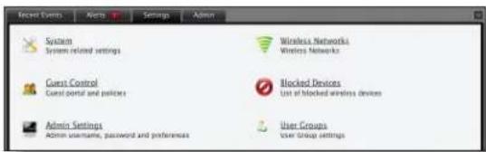
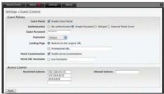
- Make sure that the Guest Portal is enabled and select an authentication method. F

- Select Enable portal customization and click apply.
Viewing the Default Portal
Once Guest Portal > Portal Customization is enabled, connect to the Guest Network SSID as below depending on your platform.
Windows
- Go to Connect to Network.
- Windows 7 Right-click on the Network 📋 icon.
- Windows Vista Go to Start > Connect To.
- Windows XP Right-click the Wireless Network icon in the System Tray (lower right corner of the screen) and then click View Available Wireless Networks.
- Select the Guest Network SSID and click Connect.
- Depending on the security type applied to the network, enter the security key or password and click OK or Connect.
- Launch your web browser and you will be directed to the default portal page for the authentication type configured on the Guest Portal (see "Authentication" on page 9 for screenshots of default portal pages by authentication method).
Mac
- Click the AirPort icon in the menu bar (top left side of the screen).
- Select the Guest Network SSID and click Connect.
- Depending on the security type applied to the network, enter the security key or password and click OK.
- Once connected, the AirPort icon will change from gray to solid black. The number of black lines indicates the signal strength.
- Launch your web browser and you will be directed to the default portal page for the authentication type configured on the Guest Portal (see "Authentication" on page 9 for screenshots of default portal pages by authentication method).
Setup
The html and css files are located on the system that the UniFi Server software has been installed on. The file paths are in the following locations:
Mac:
/Applications/UniFi.app/Contents/Resources/data/portal Windows:
For specific instructions on accessing the files, refer to the specific operating system following:
Mac
- Navigate to Go > Applications.

- Control click on the UniFi application and select Show Package Contents.

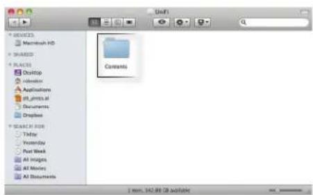
- Double-click on the Contents folder to open it.
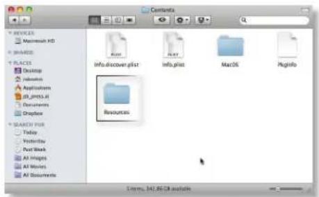
- Double-click on the Resources folder to open it.
- Double-click on the data folder to open it.

- Double-click on the portal folder to open it.

Windows
The Windows files are located in the following location:
Customizable Default Files
The following default customizable html and css files can be found in the portal folder:
- index.html The main landing page.
- payment.html Used for credit card information submission. Requires https, and also serves as an example of additional .html page.
- fail.html Page displayed when there is an error handling a guest login.
- reset-min.css
- styles.css
Another important customizable file is located in the bundle folder. The messages.properties file can be edited with a text editor such as TextEdit. This defines package costs, length of access, package titles, and how the charge will appear on a customer's credit card. Error messages are also defined here.

Additional details on portal customization can be found in our forum at:
http://www.ubnt.com/forum/showpost.php?p=205385
Appendix B: UniFi Discovery Utility
Overview
The Ubiquiti UniFi Discovery Utility includes tools that allow the discovery and management of UniFi Enterprise WiFi System Access Points. It is installed automatically as part of the UniFi Controller software installation process. See "Software Installation" on page 5 for more information.
Launching the UniFi Discovery Utility
Mac Users
From the Finder, click Go > Applications and double-click the UniFi-Discover.app icon.

PC Users
Go to Start > All Programs > Ubiquiti UniFi and double-click the UniFi-Discover icon.

UniFi Discovery Utility Interface
Upon launch, the UniFi Discovery Utility listens to Layer-2 broadcast/multicast beacons from UniFi Access Points in both factory default state and an unmanaged state (adopted but unable to contact the UniFi Controller software).
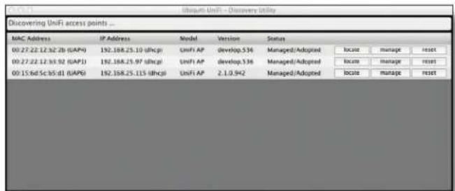
MAC Address Displays the MAC address and alias (in parentheses if specified - see "Config" on page 10 for details on specifying an alias) of the Access Point.
IP Address Displays the IP address of the Access Point and the method used by the Access Point to obtain an IP address (in parentheses as DHCP or Static).
Model Displays the model name of the UniFi WiFi System Access Point.
Version The software version installed on the Access Point is displayed here.
Status Displays the current status of the Access Point. Possible statuses include: Pending, Managed/Adopted, Login Failed, and IP Unreachable.
Locate Click to Locate the Access Point. The following window appears:

The LED on the Access Point will flash so that it can be identified from other Access Points. If the Access Point's status requires the entry of a username and password, enter it before clicking Apply.
Manage Click to set the inform URL, allowing the Access Point to be managed by an instance of the UniFi Controller software running in a NOC or in the cloud (see "Network Topology Requirements" on page 1 for a visual representation of this configuration). The following window appears:

Enter the URL, port and path to the instance of the UniFi Controller software that the Access Point is to be managed by. If the Access Point's status requires the entry of a username and password, enter it before clicking Apply.
Reset Click to restore the Access Point to factory default settings. The following window appears:

If the Access Point's status requires the entry of a username and password, enter it before clicking Apply.
Reboot Click to reboot Access Point. The following window appears:
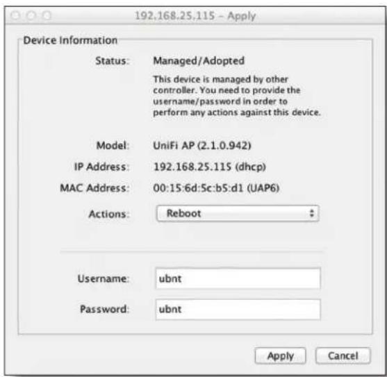
If the Access Point's status requires the entry of a username and password, enter it before clicking Apply.
Appendix C: Specifications
| UniFi AP (UAP) Specifications | |
| Dimensions 20 x 20 x 3.65 cm | |
| Weight 290 g (430 g with mounting kits) | |
| Ports Ethernet (Auto MDX, autosensing | 10/100 Mbps) |
| Buttons Reset | |
| Antennas 2 Integrated (supports 2x2 MIMO with spatial diversity) | |
| Wi-Fi Standards 802.11 b/g/n* | |
| Power Method Passive Power over Ethernet (12-24V) | |
| Power Supply 24V 0.5A PoE Adapter included | |
| Maximum Power Consumption 4W | |
| Max TX Power 20 dBm | |
| BSSID Up to four per radio | |
| Power Save Supported | |
| Wireless Security | WEP, WPA-PSK, WPA-TKIP, WPA2 AES, 802.11i |
| Certifications | CE, FCC, IC |
| Mounting | Wall/Ceiling (Kits included) |
| Operating Temperature | -10 to 70°C (14 to 158°F) |
| Operating Humidity | 5 - 80% Condensing |
| Advanced Traffic Management | |
| VLAN | 802.1Q |
| Advanced QoS | Per-user rate limiting |
| Guest traffic isolation | Supported |
| WMM | Voice, video, best effort, and background |
| Concurrent Clients | 100+ |
| Supported Data Rates (Mbps) | |
| Frequency (MHz) | |
| 802.11n | MCS0 - MCS15 (6.5 Mbps to 300 Mbps), HT 20/40 |
| 802.11b | 1, 2, 5.5, 11 |
| 802.11g | 6, 9, 12, 18, 24, 36, 48, 54 |
* 2.4GHz
| UniFi AP Long-Range (UAP-LR) Specifications | |
| Dimensions 20 x 20 x 3.65 cm | |
| Weight 290 g (430 g with mounting kits) | |
| Ports Ethernet (Auto MDX, autosensing 10/100 Mbps) | |
| Buttons Reset | |
| Antennas 2 Integrated (supports 2x2 MIMO with spatial diversity) | |
| Wi-Fi Standards 802.11 b/g/n* | |
| Power Method Passive Power over Ethernet (12-24V) | |
| Power Supply 24V 0.5A PoE Adapter included | |
| Maximum Power Consumption 6W | |
| Max TX Power 27 dBm | |
| BSSID Up to four per radio | |
| Power Save Supported | |
| Wireless Security | WEP, WPA-PSK, WPA-TKIP,WPA2 AES, 802.11i |
| Certifications | CE, FCC, IC |
| Mounting | Wall/Ceiling (Kits included) |
| Operating Temperature | -10 to 70°C (14 to 158°F) |
| Operating Humidity | 5 - 80% Condensing |
| Advanced Traffic Management | |
| VLAN | 802.1Q |
| Advanced QoS | Per-user rate limiting |
| Guest traffic isolation | Supported |
| WMM | Voice, video, best effort, and background |
| Concurrent Clients | 100+ |
| Supported Data Rates (Mbps) | |
| Frequency (MHz) | |
| 802.11n | MCS0 - MCS15 (6.5 Mbps to 300 Mbps), HT 20/40 |
| 802.11b | 1, 2, 5.5, 11 |
| 802.11g | 6, 9, 12, 18, 24, 36, 48, 54 |
* 2.4GHz
Appendix D: Safety Notices
- Read, follow, and keep these instructions.
- Heed all warnings.
- Only use attachments/accessories specified by the manufacturer.

WARNING: Do not use this product in location that can be submerged by water.

WARNING: Avoid using this product during an electrical storm. There may be a remote risk of electric shock from lightning.
Electrical Safety Information
- Compliance is required with respect to voltage, frequency, and current requirements indicated on the manufacturer's label. Connection to a different power source than those specified may result in improper operation, damage to the equipment or pose a fire hazard if the limitations are not followed.
- There are no operator serviceable parts inside this equipment. Service should be provided only by a qualified service technician.
- This equipment is provided with a detachable power cord which has an integral safety ground wire intended for connection to a grounded safety outlet.
a. Do not substitute the power cord with one that is not the provided approved type. Never use an adapter plug to connect to a 2-wire outlet as this will defeat the continuity of the grounding wire.
b. The equipment requires the use of the ground wire as a part of the safety certification, modification or misuse can provide a shock hazard that can result in serious injury or death.
c. Contact a qualified electrician or the manufacturer if there are questions about the installation prior to connecting the equipment.
d. Protective earthing is provided by Listed AC adapter. Building installation shall provide appropriate short-circuit backup protection.
e. Protective bonding must be installed in accordance with local national wiring rules and regulations.
Appendix E: Warranty
General Warranty
UBIQUITI NETWORKS, Inc ("UBIQUITI NETWORKS") represents and warrants that the Products furnished hereunder shall be free from defects in material and workmanship for a period of one (1) year from the date of shipment by UBIQUITI NETWORKS under normal use and operation. UBIQUITI NETWORKS sole and exclusive obligation under the foregoing warranty shall be to repair or replace, at its option, any defective Product that fails during the warranty period. The expense of removal and reinstallation of any item is not included in this warranty.
The foregoing warranty is exclusive and in lieu of all other warranties, express or implied, including the implied warranties of merchantability and fitness for a particular purpose and any warranties arising from a course of dealing, usage or trade practice with respect to the products. Repair or replacement in the manner provided herein shall be the sole and exclusive remedy of Buyer for breach of warranty and shall constitute fulfillment of all liabilities of UBIQUITI NETWORKS with respect to the quality and performance of the Products. UBIQUITI NETWORKS reserves the right to inspect all defective Products (which must be returned by Buyer to UBIQUITI NETWORKS factory freight prepaid).
No Products will be accepted for replacement or repair without obtaining a Return Materials Authorization (RMA) number from UBIQUITI NETWORKS. Products returned without an RMA number will not be processed and will be returned to Buyer freight collect. UBIQUITI NETWORKS shall have no obligation to make repairs or replacement necessitated by catastrophe, fault, negligence, misuse, abuse, or accident by Buyer, Buyer's customers or any other parties. The warranty period of any repaired or replaced. Product shall not extend beyond its original term.
Warranty Conditions
The foregoing warranty shall apply only if:
(I) The Product has not been subjected to misuse, neglect or unusual physical, electrical or electromagnetic stress, or some other type of accident.
(II) No modification, alteration or addition has been made to the Product by persons other than UBIQUITI NETWORKS or UBIQUITI NETWORK'S authorized representatives or otherwise approved by UBIQUITI NETWORKS.
(III) The Product has been properly installed and used at all times in accordance, and in all material respects, with the applicable Product documentation.
(IV) All Ethernet cabling runs use CAT5 (or above) shielded cabling.
Disclaimer
UBIQUITI NETWORKS does not warrant that the operation of the products is error-free or that operation will be uninterrupted. In no event shall UBIQUITI NETWORKS be responsible for damages or claims of any nature or description relating to system performance, including coverage, buyer's selection of products for buyer's application and/or failure of products to meet government or regulatory requirements.
Returns
In the unlikely event a defect occurs, please work through the dealer or distributor from which this product was purchased.
Appendix F: Compliance Information
Installer Compliance Responsibility
Devices must be professionally installed and it is the professional installer's responsibility to make sure the device is operated within local country regulatory requirements.
FCC
Changes or modifications not expressly approved by the party responsible for compliance could void the user's authority to operate the equipment. NOTE: This equipment has been tested and found to comply with the limits for a Class A digital device, pursuant to part 15 of the FCC Rules. These limits are designed to provide reasonable protection against harmful interference when the equipment is operated in a commercial environment. This equipment generates, uses, and can radiate radio frequency energy and, if not installed and used in accordance with the instruction manual, may cause harmful interference to radio communications. Operations of this equipment in a residential area is likely to cause harmful interference in which case the user will be required to correct the interference at his own expense. The antennas used for this transmitter must be installed to provide a separation distance of at least the following from all users: 20 cm.
Industry Canada
This Class A digital apparatus complies with Canadian ICES-003.
Operation is subject to the following two conditions:
- This device may not cause interference, and
- This device must accept any interference, including interference that may cause undesired operation of the device.
To reduce potential radio interference to other users, the antenna type and its gain should be so chosen that the equivalent isotropically radiated power (e.i.r.p.) is not more than that permitted for successful communication.
RF Exposure Warning
The transceiver described here emits radio frequency energy. Although the power level is low, the concentrated energy from a directional antenna may pose a health hazard. Do not allow people to come closer than 157 cm to the antenna when the transmitter is operating.
Additional information on RF exposure is available on the Internet at www.fcc.gov/oet/info/documents/bulletins
CE marking on this product represents the product is in compliance with all directives that are applicable to it.
Alert sign! Follows CE marking
Alert sign must be indicated if a restriction on use applied to the
product and it must follow the CE marking.

NB-Identification number (if there is any)
Notified body number is indicated if it is involved in the conformity assessment procedure.

Please check the CE mark on the product label to find out which notified body was involved during assessment.
RoHS/WEEE Compliance Statement

English
European Directive 2002/96/EC requires that the equipment bearing this symbol on the product and/or its packaging must not be disposed of with unsorted municipal waste. The symbol indicates that this product should be disposed of separately from regular household waste streams. It is your responsibility to dispose of this and other electric and electronic equipment via designated collection facilities appointed by the government or local authorities. Correct disposal and recycling will help prevent potential negative consequences to the environment and human health. For more detailed information about the disposal of your old equipment, please contact your local authorities, waste disposal service, or the shop where you purchased the product.
Deutsch
Appendix G: Declaration of Conformity
| Česky [Czech] | UBIQUITI NETWORKS tímto prohla uje, e tento UBIQUITI NETWORKS device, je ve shod se základními po adavky a dal imi p islu n mi ustanoveními sm rmice 1999/5/ES. |
| Dansk [Danish] | Undertegnede UBIQUITI NETWORKS erklærer herved, at følgende udstyr UBIQUITI NETWORKS device, overholder de væsentlige krav og øvrige relevante krav i direktiv 1999/5/EF. |
| Nederlands [Dutch] | Hierbij verklaart UBIQUITI NETWORKS dat het toestel UBIQUITI NETWORKS device, in overeenstemming is met de essentiële eisen en de andere relevante bepalingen van richtlijn 1999/5/EG.Bij deze verklaart UBIQUITI NETWORKS dat deze UBIQUITI NETWORKS device, voldoet aan de essentiële eisen en aan de overige relevante bepalingen van Richtlijn 1999/5/EC. |
| English | Hereby, UBIQUITI NETWORKS, declares that this UBIQUITI NETWORKS device, is in compliance with the essential requirements and other relevant provisions of Directive 1999/5/EC. |
| Eesti [Estonian] | Käesolevaga kinnitab UBIQUITI NETWORKS seadme UBIQUITI NETWORKS device, vastavust direktiivi 1999/5/EÜ põhinõutele ja nimetatud direktiivist tulenevatele teistele asjakohastele sätetele. |
| Suomi [Finnish] | UBIQUITI NETWORKS vakuuttaa täten että UBIQUITI NETWORKS device, typpinen laite on direktiivin 1999/5/EY oleellisten vaatimusten ja sitä koskevien direktiivin muiden ehtojen mukainen. |
| Français [French] | Par la présente UBIQUITI NETWORKS déclare que l'appareil UBIQUITI NETWORKS, device est conforme aux exigences essentielles et aux autres dispositions pertinentes de la directive 1999/5/CE.Par la présente, UBIQUITI NETWORKS déclare que ce UBIQUITI NETWORKS device, est conforme aux exigences essentielles et aux autres dispositions de la directive 1999/5/CE qui lui sont applicables. |
| Deutsch [German] | Hiermit erklärt UBIQUITI NETWORKS, dass sich diese UBIQUITI NETWORKS device, in Übereinstimmung mit den grundlegenden Anforderungen und den anderen relevanten Vorschriften der Richtlinie 1999/5/EG befindet". (BMWi)Hiermit erklärt UBIQUITI NETWORKS die Übereinstimmung des Gerätes UBIQUITI NETWORKS device, mit den grundlegenden Anforderungen und den anderen relevanten Festlegungen der Richtlinie 1999/5/EG. (Wien) |
| Ελληνική [Greek] | ME THN ΠΑΡΟΥΣΑ UBIQUITI NETWORKS ΔΗΛΩΝΕΙ ΟΤΙ UBIQUITI NETWORKS device, ΣΥΜΜΟΡΦΩΝΕΤΑΙ ΠΡΟΣ ΤΙΣ ΟΥΣΙΩΔΕΙΣ ΑΠΑΙΤΗΣΕΙΣ ΚΑΙ ΤΙΣ ΛΟΙΠΕΣ ΣΧΕΤΙΚΕΣ ΔΙΑΤΑΞΕΙΣ ΤΗΣ ΟΔΗΓΙΑΣ 1995/5/EK. |
| Magyar [Hungarian] | Alulírott, UBIQUITI NETWORKS nyilatkozom, hogy a UBIQUITI NETWORKS device, megfelel a vonatkozó alapvető követelményeknek és az 1999/5/EC irányelv egyéb előírásainak. |
| Íslenska [Icelandic] | Hér me I sir UBIQUITI NETWORKS yfir ví a UBIQUITI NETWORKS device, er í samræmi vi grunnkröfur og a rar kröfur, sem ger ar eru í tilskipun 1999/5/EC. |
| Italiano [Italian] | Con la presente UBIQUITI NETWORKS dichiara che questo UBIQUITI NETWORKS device, è conforme ai requisiti essenziali ed alle altre disposizioni pertinenti stabilite dalla direttiva 1999/5/CE. |
| Latviski [Latvian] | Ar o UBIQUITI NETWORKS deklar, ka UBIQUITI NETWORKS device, atbilst Direkt vas 1999/5/EK b tiskaj m pras b m un citiem ar to saist tajiem noteikumiem. |
| Lietuvi [Lithuanian] | UBIQUITI NETWORKS deklaruoja, kad šis UBIQUITI NETWORKS jrenginys atitinka esminius reikalavimus ir kitas 1999/5/EB Direktyvos nuostatas. |
| Malti [Maltese] | Hawnhekk, UBIQUITI NETWORKS, jiddikjara li dan UBIQUITI NETWORKS device, jikkonforma mal- ti ijiet essenzjali u ma provvedimenti o rajn relevanti li hemm fid-Dirrettiva 1999/5/EC. |
| Norsk [Norwegian] | UBIQUITI NETWORKS erklærer herved at utstyret UBIQUITI NETWORKS device, er i samsvar med de grunnleggende krav og øvrige relevante krav i direktiv 1999/5/EF. |
| Slovensky [Slovak] | UBIQUITI NETWORKS t mto vyhlasuje, e UBIQUITI NETWORKS device, sp a základné po iadavky a v etky prislu né ustanovenia Smernice 1999/5/ES. |
| Svenska [Swedish] | Härmed intygar UBIQUITI NETWORKS att denna UBIQUITI NETWORKS device, står l överensstämmelse med de väsentliga egenskapskrav och övriga relevanta bestämmelser som framgår av direktiv 1999/5/EG. |
| Español [Spanish] | Por medio de la presente UBIQUITI NETWORKS declara que el UBIQUITI NETWORKS device, cumple con los requisitos esenciales y cualesquiera otras disposiciones aplicables o exigibles de la Directiva 1999/5/CE. |
| Polski [Polish] | Niniejszym, firma UBIQUITI NETWORKS o wiadcza, e produkt serii UBIQUITI NETWORKS device, spełnia zasadnicze wymagania i inne istotne postanowienia Dyrektywy 1999/5/EC. |
| Português [Portuguese] | UBIQUITI NETWORKS declara que este UBIQUITI NETWORKS device, está conforme com os requisitos essenciais e outras disposições da Directiva 1999/5/CE. |
| Română [Romanian] | Prin prezenta, declarăm că acest produs este în conformitate cu cerințele esențiale și cu alte prevederi relevante din Directiva 1999/5/CE. |
Appendix H: Contact Information
Ubiquiti Networks Support
Ubiquiti Support Engineers are located in the U.S. and Europe and are dedicated to helping customers resolve software, hardware compatibility, or field issues as quickly as possible. We strive to respond to support inquiries within a 24 hour period.
Email: support@ubnt.com
Phone: 408-942-1153 (9 a.m. - 5 p.m. PST)
Online Resources
Wiki Page: www.ubnt.com/wiki
Support Forum: www.ubnt.com/forum
Downloads: www.ubnt.com/support/downloads

91 E. Tasman Drive
San Jose, CA 95134
www.ubnt.com
© 2011 Ubiquiti Networks, Inc. All rights reserved. UniFi is a trademark of Ubiquiti Networks, Inc. Google Maps™ is a trademark of Google, Inc. PayPal is a trademark of PayPal, Inc.
- TABLE OF CONTENTS
- CHAPTER 1: PRODUCT OVERVIEW ....1
- CHAPTER 2: INSTALLATION ....3
- CHAPTER 3: USING THE UNIFI CONTROLLER SOFTWARE....7
- CHAPTER 4: MAP TAB....13
- CHAPTER 5: STATISTICS TAB ....20
- CHAPTER 6: ACCESS POINTS TAB....22
- CHAPTER 7: USERS TAB....23
- CHAPTER 8: GUESTS TAB 24
- CHAPTER 9: OFFLINE CLIENTS TAB .... 25
- CHAPTER 10: ACCESS POINT DETAILS....26
- CHAPTER 11: USER/GUEST DETAILS ...... 34
- CHAPTER 12: HOTSPOT MANAGER....36
- APPENDIX A: PORTAL CUSTOMIZATION....38
- APPENDIX B: UNIFI DISCOVERY UTILITY 40
- APPENDIX C: SPECIFICATIONS 42
- APPENDIX D: SAFETY NOTICES....44
- APPENDIX E: WARRANTY 45
- APPENDIX F: COMPLIANCE INFORMATION 46
- APPENDIX G: DECLARATION OF CONFORMITY....48
- APPENDIX H: CONTACT INFORMATION....49
- CHAPTER 1: PRODUCT OVERVIEW
- SYSTEM REQUIREMENTS
- NETWORK TOPOLOGY REQUIREMENTS
- BACK
- CHAPTER 2: INSTALLATION
- HARDWARE INSTALLATION
- MOUNTING THE ACCESS POINT
- WALL-MOUNT
- CEILING-MOUNT
- SOFTWARE INSTALLATION
- MAC USERS
- PC USERS
- CONFIGURING THE UNIFI CONTROLLER SOFTWARE
- CHAPTER 3: USING THE UNIFI CONTROLLER SOFTWARE
- INTERFACE TABS
- COMMON INTERFACE OPTIONS
- ACCESS POINTS
- STATIONS
- RECENT EVENTS
- CLICKING ON AN EVENT DEVICE LINK
- ALERTS
- SYSTEM CONFIGURATION
- SERVICES
- MAIL SERVER
- SETTINGS > GUEST CONTROL
- GUEST POLICIES
- HOTSPOT
- ACCESS CONTROL
- SETTINGS > ADMIN SETTINGS
- SETTINGS > WIRELESS NETWORKS
- WIRELESS CONFIGURATIONS
- WIRELESS CONFIGURATION
- ADVANCED
- SETTINGS > BLOCKED DEVICES
- SETTINGS > USER GROUPS
- ADMIN
- SERVER INFORMATION
- BACKUP
- RESTORE
- SUPPORT INFO
- CHAPTER 4: MAP TAB
- ADDING A GOOGLE MAP™
- HTTP://CODE.GOOGLE.COM/APIS/MAPS/SIGNUP.HTML
- PLACING ACCESS POINTS ON THE MAP
- USERS 0
- GUESTS 0
- SETTING THE MAP SCALE
- CHAPTER 5: STATISTICS TAB
- CLIENTS
- QUICK LOOK
- CURRENT USAGE - TOP ACCESS POINTS
- RECENT ACTIVITIES
- CHAPTER 6: ACCESS POINTS TAB
- CHAPTER 7: USERS TAB
- CHAPTER 8: GUESTS TAB
- CHAPTER 9: OFFLINE CLIENTS TAB
- CHAPTER 10: ACCESS POINT DETAILS
- DETAILS
- USERS 1
- UPLINK (WIRELESS)
- UPLINK (WIRE)
- DOWNLINKS
- RADIO (11N/B/G)
- USERS
- GUESTS
- CONFIGURATION
- CONFIG
- GENERAL SETTINGS
- WLANS
- NETWORK
- WIRELESS UPLINKS
- ACCESS POINT - HEARTBEAT MISSED
- ACCESS POINT - ISOLATED
- ACCESS POINT - MANAGED BY OTHER
- CHAPTER 11: USER/GUEST DETAILS
- OVERVIEW
- STATISTICS
- HISTORY
- DEBUG
- CHAPTER 12: HOTSPOT MANAGER
- WIRELESS GUESTS
- ACTIONS
- PAYMENTS/TRANSACTIONS
- VOUCHERS
- OPERATOR ACCOUNTS
- APPENDIX A: PORTAL CUSTOMIZATION
- ENABLING PORTAL CUSTOMIZATION
- VIEWING THE DEFAULT PORTAL
- WINDOWS
- MAC
- SETUP
- CUSTOMIZABLE DEFAULT FILES
- APPENDIX B: UNIFI DISCOVERY UTILITY
- LAUNCHING THE UNIFI DISCOVERY UTILITY
- UNIFI DISCOVERY UTILITY INTERFACE
- APPENDIX D: SAFETY NOTICES
- ELECTRICAL SAFETY INFORMATION
- APPENDIX E: WARRANTY
- GENERAL WARRANTY
- WARRANTY CONDITIONS
- DISCLAIMER
- RETURNS
- APPENDIX F: COMPLIANCE INFORMATION
- INSTALLER COMPLIANCE RESPONSIBILITY
- FCC
- INDUSTRY CANADA
- RF EXPOSURE WARNING
- ALERT SIGN! FOLLOWS CE MARKING
- NB-IDENTIFICATION NUMBER (IF THERE IS ANY)
- ROHS/WEEE COMPLIANCE STATEMENT
- ENGLISH
- DEUTSCH
- APPENDIX H: CONTACT INFORMATION
- UBIQUITI NETWORKS SUPPORT
- ONLINE RESOURCES
Brand : Ubiquiti Networks
Model : UAP-LR
Category : Access Point