
ST 2800 - Motion detector STEINEL - Free user manual and instructions
Find the device manual for free ST 2800 STEINEL in PDF.


| Type | Motion detector |
| Brand | Steinel |
| Model | ST 2800 |
| Dimensions (H x W x D) | 150 x 80 x 80 mm |
| Weight | 200 g |
| Power supply | 230 V AC, 50 Hz |
| Detection range | Up to 12 m (tangential) |
| Detection angle | 180° |
| Time setting | 5 seconds to 15 minutes |
| Twilight setting | 2 to 2000 lux |
| Mounting height | 2.5 m recommended |
| IP rating | IP44 |
| Material | Plastic (UV-resistant) |
| Color | White |
| Functions | Automatic switching, adjustable time and twilight, manual override |
| Maintenance | Clean with a soft damp cloth; do not use solvents |
| Safety | Disconnect power before installation or maintenance |
| Spare parts | Not available (integrated unit) |
| Repairability | Non-repairable; replace unit if defective |
| General information | For outdoor wall-mounting; suitable for driveways, gardens, entrances |
Frequently Asked Questions - ST 2800 STEINEL
User questions about ST 2800 STEINEL
0 question about this device. Answer the ones you know or ask your own.
Ask a new question about this device
Download the instructions for your Motion detector in PDF format for free! Find your manual ST 2800 - STEINEL and take your electronic device back in hand. On this page are published all the documents necessary for the use of your device. ST 2800 by STEINEL.
USER MANUAL ST 2800 STEINEL
- Manesty Road - Axis Park - Crion Southgate
GB-Peterborough Cambs PE2 6UP
Tel: +44/1733/366-700 · Fax: +44/1733/366-701
steine@steinel.co.uk
IRL Socket Tool Company Ltd
Unit 714 NorthWest Business Park
Kisharo Drive · Ballycoolin Dublin 15
Tel.: 00353 1 8809120 · Fax: 00353 1 5612031
info@sockettool.ie
F STEINEL FRANCE SAS
Representative Office
Shanghai Rm. 21 A-C, - Huacu Mansion No. 838
Zhangwano Road Shanghai 200122
Tel: +96 21 5820 /486, Fax: +96 21 5820 /4212
www.stinel.cn · info@stinel.net

PROFESSIONAL


Information
HF 360 COM 1
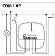
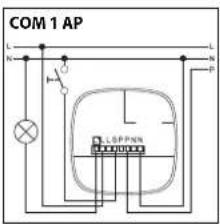
HF 360 COM1 AP
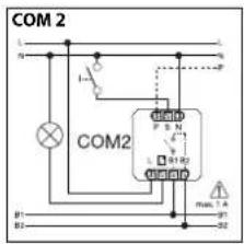
HF 360 COM 2
HF 360 DIM
DUAL HF COM 1
DUAL HF COM 1 AP
DUAL HF DIM
CONTROL

SYSTEM
13

-2--3-
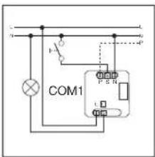
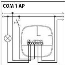
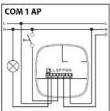
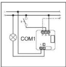
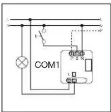
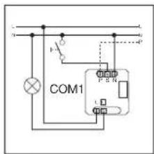
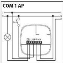
HF 360 COM 1/COM 1 AP / DUAL HF COM 1/COM 1 AP


-4--5-
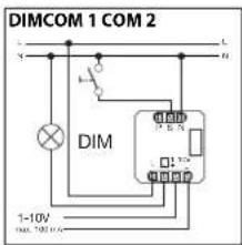
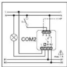
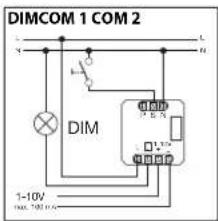
HF 360 DIM / DUAL HF DIMHF 360 COM 2

14
![graph TD A["Master"] --> B["PSN"] B --> C["L"] C --> D["N"] D --> E["Switch 1"] E --> F["Master"] F --> G["PSN"] G --> H["L"] H --> I["N"] I --> J["Switch 2"] J --> K["Master"] K --> L["PSN"] L --> M["L"] M --> N["N"] N --> O["Switch 3"] O --> P["Master"] P --> Q["PSN"] Q --> R["L"] R --> S["N"] S -…](/content/2026/06/1265969/images/f0e1e1fff57b1e7599d64b51128b368707b526a36a22d77f0e851c1e236b0bec.jpg)


-6--7-
14


* cable length < 50 m
14

-8--9-
16
HF 360

Bedienungsanleitung

Operating instructions
Dear Customer,
Congratulations on purchasing your new STEINEL presence detector and thank you for the confidence you have shown in us. You have chosen a high-quality product that has been manufactured, tested and packed with the greatest care.
Please familiarise yourself with these instructions before attempting to install the presence detector because prolonged, reliable and trouble-free operation will only be ensured if it is fitted and used properly.
We hope your new STEINEL sensor will bring you lasting pleasure.

Safety warnings
■ Disconnect the power supply before attempting any work on the sensor!
During installation, the electric power cable to be connected must be dead. Therefore, switch 'OFF' the power first and use a voltage tester to make sure the wiring is off circuit.
■ Installing the sensor involves work on the mains power supply. This work must therefore be carried out professionally in accordance with the applicable national wiring regulations and electrical operating conditions (VDE 0100).
It is only permissible to use electronic ballasts with Isolated control signal at the DIM 1-10 V control output.
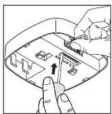
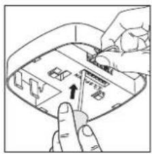
Assembly/Installation ⑬ (see chart on page 2)
The sensor is only intended for concealed, indoor installation in ceilings (apart from the COM 1 AP - surface-mounted - option). A clamping-type ceiling adapter or surface-mounting adapter is not included.
Sensor and load module come ready assembled and must be plugged together after fitting the load module and setting the potentiometers/dip switches.
Accessories: Clamping-type ceiling adapter, EAN no.: 4007841 000370 Surface-mounting adapter, EAN no.: 4007841 000363 Guard cage, EAN no.: 4007841 003036 Service remote control, EAN no.: 4007841 000387 User remote control, EAN no.: 4007841 003012
System components
① Load module
② Sensor module
③ Sensor base
④ Dip switches
(1) Normal/test mode
(2) Semi-/fully automatic mode
(3) Button/switch
(4) 'ON' / 'ON'-OFF' button
(5) DIM option
Constant lighting control 'ON'/OFF'
⑤ Twilight setting
⑥ Time setting
Switching output 1
⑦ HVAC stay-'ON' time
Switching output 2
⑧ HVAC switch-'ON' delay Switching output 2
⑨ Reach setting
⑩ Clamping-type ceiling adapter, optional
⑪ Surface-mounting adapter IP 54, optional
⑫ Locking mechanism
⑬ Assembly/Installation
⑭ Parallel-connected configurations
⑮ Stay-'ON' time Orientation light DIM option
⑯ Film shroud for minimising the detection zone (HF 360).
How it works / Basic function
The high-frequency presence detectors from the Control PRO range control lighting as well as heating, ventilation and air-conditioning (COM 2 only), e.g. in offices, WCs, public buildings or at home, in relation to ambient light level and the presence of persons. Modern, high-frequen-
cy technology guarantees that movement is detected absolutely anywhere irrespective of radiated temperature. Sensing movement in two directions, the DUAL HF sensor is ideal for corridors in hotels, schools and office buildings. The presence detector's switching outputs and
reach are set at the potentiometers and dip switches or by means of the optional remote control. Presence Control has a low intrinsic power consumption.
Presence Control PRO HF 360 COM 1 / COM 1 AP DUAL HF COM 1 / COM 1 AP
1 switching output operating in relation to brightness setting and presence of persons.
Settings:
- Brightness setting
- Stay-'ON' time, pulse mode, IQ mode
Presence Control PRO HF 360 COM 2
1 switching output, such as COM 1. Plus a 2nd switching output for HVAC (heating / ventilation / air conditioning) governed by presence.
Settings:
- Stay-'ON' time
- Switch-'ON' delay
- Room surveillance
Presence Control PRO HF 360 DIM DUAL HF DIM
1 switching output operating in relation to brightness setting and presence of persons.
Settings:
- Brightness setting
- Stay-'ON' time, IQ mode
- Orientation light
- Constant lighting control
Detection zone

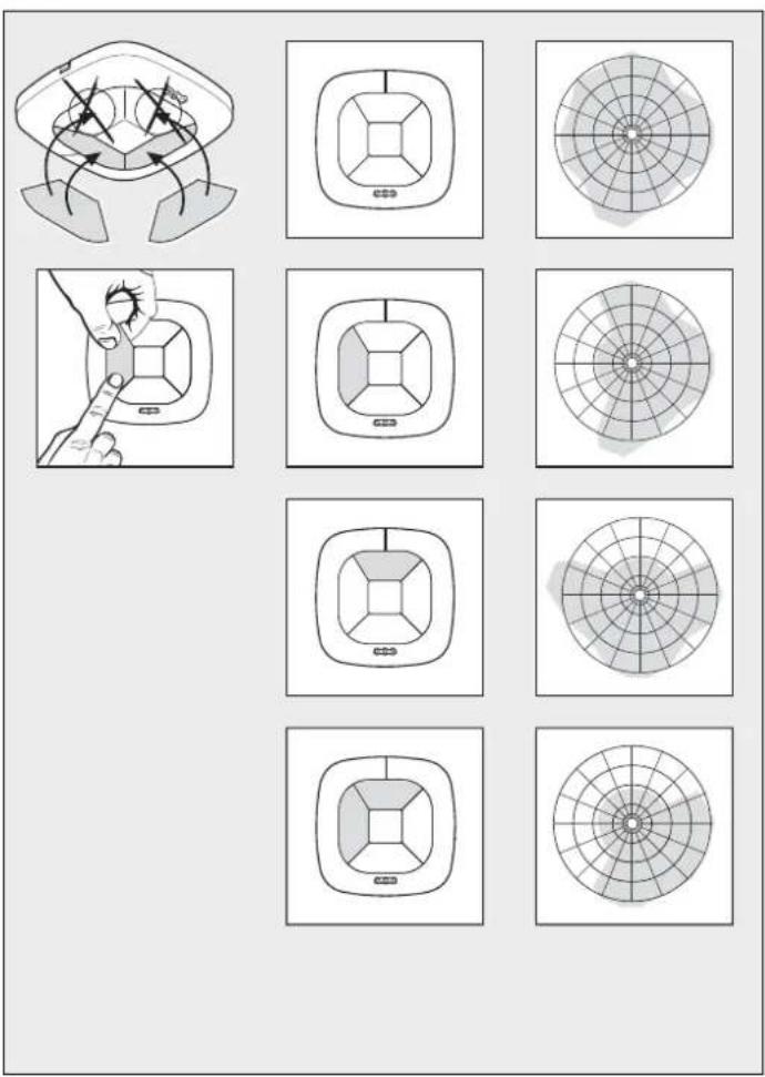
The reach of the HF 360 is electronically adjustable. 1 or 2 detection directions can be masked out for adjustment to the room situation. An angle of coverage of 360° provides a max. reach of 8m .
The DUAL HF sensor has 2 special HF sensors that detect movement from the ceiling in both directions. Controlled electronically, reach is infinitely variable in both directions from 3 × 3 m - 10 × 3 m .
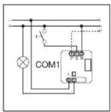
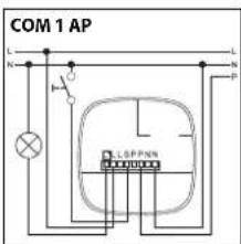
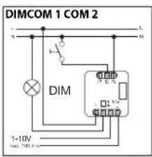
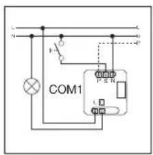
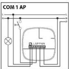
In selecting the wiring leads, it is important to meet the wiring regulations laid down In VDE 0100 (see Safety warnings on page 19). The following applies to wiring presence detectors: According to

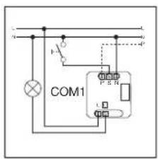

section 6 of VDE 0100 520, a multiple-core lead containing both the mains voltage leads and the control leads (e.g. NYM 5 x 1.52) may be used for wiring between the sensor and electronic ballast. The
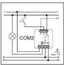

mains connection lead must be no greater than 10 mm in diameter. The clamping range of the mains terminal is designed for a maximum of 2 x 1.5 mm 2 or 1 x 2.5 mm 2 .
Technical Specifications Electrical installation/Automatic mode
| Dimensions(w x h x d) | HF 360120 x 120 x 56 mm | Dual HF120 x 120 x 76 mm |
| Supply voltage 230 - 240 V, 50 Hz / 60 Hz | ||
| Capacity, switching output 1(COM 1/COM 2) | Relay 230 VResistive load 2000 W max. (cos φ = 1)1000 VA max. (cos φ = 0,5) | |
| Electronic ballast:(COM 1/COM 1 AP/COM 2/DIM) | Max. 'ON' current 800 A/200 μs30 x (1 x 18 W), 25 x (2 x 18 W)25 x (1 x 36 W), 15 x (2 x 36 W)20 x (1 x 58 W), 10 x (2 x 58 W)Pay attention to specific 'ON' currents of electronic ballasts!A relay or contactor must be provided on line side for higher switching capacities. | |
| Capacity, switching output 2(COM 2 only) (HF 360 only) | Presence230 W max. / 230 V1A max. (cos φ = 1) for HVAC (heating/ventilation/air-conditioning) | |
| Application indoors | ||
| Mounting height(mounted to ceiling) | 2.5 m - 3.5 m ceiling height | |
| Detection angle HF 360 | 360° with 140° aperture angle also through glass, wood and stud walls. 1 or 2 detection directions can be masked out for adjustment to the room situation. | Dual HFsee diagrams on p. 21also through glass, wood and stud walls |
| Reach HF 360 | 8 m max. all round, electronically and infinitely variable | Dual HF10 x 3 m max. in each direction, electronically and Infinitely adjustable |
| Switching output 1Time setting | 30 sec. - 30 min., pulse mode (approx. 2 sec.)IQ mode (automatic adjustment to use profile) | |
| Switching output 2Time setting(HF 360 only) | COM2 only for HVAC0 sec. - 10 min. switch-'ON' delay1 min. - 2 h stay 'ON' timeAutomatic room surveillance | |
| DIM:Time settingControl output | 30 sec. - 30 min.IQ mode (automatic adjustment to use profile)1 - 10 V / max. of 50 electronic ballasts, max. of 100 mA | |
| Sensor system High-frequency 5.8 GHz, transmission power < 1mW | ||
| Function setting byDIP switches | DIP 1 Normal / test modeDIP 2 Semi- / fully automatic modeDIP 3 Button / switch modeDIP 4 'ON' button / 'ON-'OFF' buttonDIP 5 Constant-lighting control 'ON-'OFF' (DIM) | |
| Parallel connections Master/slaveMaster/master | ||
| User-friendly setting capability Teach-in (with optional remote control RC3) | ||
| Light-level setting 10 - 1000 lux, ≈ / daylightDIM 100 - 1000 lux | ||
| IP rating | IP 20 (IP 54 with surface-mounted box) | |
| Safety class | II | |
| Temperature range | 0" to +40°C | |
| Housing | UV-resistant, paintable | |
Functions – Settings by DIP switch
COM 1 + COM 2
DIP 1
Normal mode / Test mode (NORM / TEST)
Test mode has priority over all other settings on the presence detector and serves the purpose of checking for proper working order as well for testing the detection zone. Irrespective of am-
bient light level, the presence detector activates the light to stay 'ON' for approx. 8 sec. in response to movement in the room (blue LED flashes when movement is detected). All user-
selected potentiometer settings apply in normal mode. The presence detector can also be set by means of the blue LED without any load connected.
DIP 2
Semi-automatic mode (MAN) / fully automatic mode (AUTO)
Semi-automatic mode: (MAN)
The light now only switches 'OFF' automatically. Light is switched 'ON' manually. Light must be requested using the
button and stays 'ON' for the time set at the potentiometer. (pressing twice switches 'ON' for 4 hours).
Fully automatic mode: (AUTO)
The light automatically switches 'ON' and 'OFF' in relation to brightness when someone is present. Light can be switched 'ON' and 'OFF' manually at any time. This temporarily interrupts
the automatic switching function. Irrespective of the settings selected, light stays 'ON' for 4 hours after manually pressing the button twice or switches 'OFF' after manually pressing the
button once. Pressing the button before the 4 hours elapse returns the Presence Control IR Quattro to the normal operating mode.
DIP 3
Button/switch
Tells the sensor how to interpret the incoming signal. Assigning external buttons/switches allows you to operate the detector as a semi-automatic unit and override it manually at any time.
- Operation either by button or switch - Several buttons possible on one control input - Only use illuminated push-button with neutral conductor connected
■ Cable length between sensor and switch < 50 m
DIP 4
'ON'/'ON'-OFF' button
In the 'ON'-OFF' setting, the light can be switched 'ON' and 'OFF' manually at any time (except in
pulse mode: no manual 'OFF'). In the 'ON' setting, light can no longer be switched 'OFF' manu-
ally. The stay-'ON' time starts from the beginning again each time the button is pressed.
DIM
DIP 5
Constant light 'ON'/'OFF'
Provides a constant level of brightness. Detector measures the prevailing level of daylight and activates sufficient artificial light to achieve the required lev
el of brightness. As daylight changes, the switched-in artificial lighting component is adjusted accordingly. In addition to the daylight component, artificial
light is also switched 'ON' and 'OFF' in relation to whether or not persons are present.
Functions – Settings by potentiometer
COM 1 + COM 2
Potentiometer ⑤
Twilight setting
The chosen response threshold can be infinitely varied from approx. 10 - 1000 lux.
Control dial turned fully clockwise: MAX daylight mode Control dial turned fully anti-clockwise: MIN night-time operation
Depending on the site of installation, the setting may need to be corrected by 1-2 marks on the scale.
| Examples of use Brightness settings | |
| Night-time mode min | |
| Corridors, foyers 1 | |
| Stairs, escalators, moving walkways 2 | |
| Washrooms, toilets, switchrooms, canteens 3 | |
| Sales floor, kindergartens, nursery school rooms, sports halls | 4 |
| Work environments: Offices, conference and meeting rooms, precision assembly activities, kitchens | 5 |
| Working areas requiring good light:Laboratory, technical drawing, precision work | >=6 |
| Daylight mode max |
Note: Depending on the site of installation, the setting may need to be corrected by 1 - 2 marks on the scale.
Potentiometer ⑥
Time setting
Stay-'ON' time for switching output 1 Setting 30 sec. – 30 min.
The chosen stay-'ON' time is infinitely variable from a minimum of approx. 30 sec. to a maximum of 30 min. Light is calibrated after
3 min. When the threshold is exceeded, the sensor switches 'OFF' after the stay-'ON' time expires.
Pulse mode (except DIM) ∠
If the dial is set to ∩ (fully anticlockwise), the unit is in pulse mode, i.e. the output is switched 'ON' for approx. 2 sec. (e.g. for stair-
well lighting timer). Afterwards, the sensor does not respond to movement for approx. 8 sec.
Day mode is the only mode possible here because of dazzle by light from external sources.
IQ mode
Turned fully clockwise: The stay-'ON' time is self-learning and adjusts dynamically to user behav-
iour. The optimum time cycle is determined by means of a learning algorithm.
The shortest time is 5 min., the longest 20 min.
COM 2
Potentiometer⑦
Stay-'ON' time for switching output 2 HVAC
- Setting 1 sec. – 2 hr.
- Turned fully clockwise: max
- Turned fully anti-clockwise: min
Potentiometer ⑧
Switch-'ON' delay for switching output 2 HVAC
- Setting 0 sec. - 10 min.
- Turned fully clockwise: Room surveillance
- Turned fully anti-clockwise: 0 sec. ('OFF')
Turning the potentiometer to the "Surveillance" setting reduces the sensitivity of the "Presence" switching output. The contact only closes on detecting a pronounced movement, signaling with a high degree of certainty that persons are present.
The stay-'ON- time remains active. The switch-'ON' delay is inactivated.
Potentiometer 15
Basic brightness (DIM option)
Provides basic illumination for the selected stay-'ON' time when ambient light falls below the selected brightness threshold that is set. This can be dimmed to 10% of maximum light intensity. As soon as a person enters the scene, the detector switches either to 100% light
intensity (constant-lighting controller 'OFF') or adjusts to the preselected brightness level (constant-lighting controller 'ON'). When no movement is being detected, the detector dims back to basic brightness after the stay-'ON' time expires. This is switched 'OFF' when stay-'ON'
time (1 min. - 30 min.) has expired or the daylight component is sufficient to exceed the selected level of brightness. In the 'ON' setting, the detector switches basic brightness 'ON' and 'OFF' as soon as the level of light falls below the brightness threshold.
Reach adjustment
Potentiometer ⑨
The reach required (response threshold) is infinitely variable
■ HF 360 1 m min. - 8 m max.
■ DUAL HF min. 3 x 3 m – 10 x 3 m in each direction
Turned fully anticlockwise (factory setting) = minimum reach
Turned fully clockwise (factory setting) = maximum reach
Parallel-connected configurations
When using several detectors, they must be connected to the same phase!

Master/master
A parallel-connected configuration also permits the use of several masters. In this case, each master operates the lighting group in accordance with the level of
brightness it measures. Delay times and brightness thresholds are selected at each master as required. The switched load is spread among the individual masters.
Presence is still detected collectively by all detectors. The presence output can be picked off from any master.

Master/slave
The master/slave configuration permits detection of movement in large-type rooms or spaces (load connected = master, no load =
slave). The level of brightness prevailing in the room is only evaluated at the master. The slaves report movements detected to the mas-
ter. Lighting or HVAC is switched 'ON' and 'OFF' by the master only.

o detectors linked with an external stairwell lighting timer
Old building / building modernisation
External light source activated by button. No twilight mode, day mode only.

tector as stairwell lighting timer

DIM detector
Remote control
Using the remote control (optional), functions can be conveniently activated from the floor.
Note: The pulse mode cannot be overridden by the remote control. Switch pulse mode 'OFF' manually.
Presence Control remote control unit: EAN no.: 4007841 000387
Troubleshooting
Malfunction Cause Remedy
| Light does not switch 'ON' | No supply voltageLux setting too lowNo motion detection | Check supply voltageSlowly increase lux setting until light switches 'ON'Ensure unobstructed sensor visionCheck detection zone |
| Light does not switch 'OFF' | Lux setting too highStay-'ON' time running outInterference from sources of heat, e.g.: fan heater, open doors and windows, pets, light bulb/halogen floodlight, moving objects | Reduce lux settingWait until stay-'ON' time elapses; reduce stay-'ON' time if necessaryUse stickers to mask out stationary sources of interference |
| Sensor switches 'OFF' in spite of persons being present | Stay-'ON' time too shortLight-level threshold too low | Increase stay-'ON' timeChange light threshold |
| Sensor does not switch 'OFF' quickly enough | Stay-'ON' time too long | Reduce stay-'ON' time |
| Sensor does not switch 'ON' quickly enough when approached from the front | Reach is reduced when approached from the front | Install additional sensorsReduce distance between two sensors |
| Sensor does not switch 'ON' when persons are present in spite of it being dark | Lux setting too low | Sensor deactivated by switch/button?Semi-automatic mode?Increase light-level threshold |
CE Declaration of Conformity
This product complies with
- Low Voltage Directive 2006/95/EC
- EMC Directive 2004/108/EC
- RoHS Directive 2011/65/EC
- WEEE Directive 2012/19/EC
Functional Warranty
This Steinel product has been manufactured with utmost care, tested for proper operation and safety and then subjected to random sample inspection. Steinel guarantees that it is in perfect condition and proper working order.
The warranty period is 36 months and starts on the date of sale to the consumer. We will remedy defects caused by material flaws or manufacturing faults. The warranty will be met by repair or replacement of the defective parts at our own discretion. The warranty shall not cover damage to wear parts, damage or defects caused by improper treatment or maintenance. Further consequential damage to other objects is excluded.
Claims under the warranty will only be accepted if the product is sent fully assembled and well packed complete with a brief description of the fault as well as a receipt or invoice (date of purchase and dealer's stamp) to the appropriate Service Centre.
FUNCTIONAL
36 month
WARRANTY

Návod k obsluze
Vážený zákazníku,


Technická data



Technické údaje


Dane techniczne
Mult stimate client,




Tehnični podatki


Tehnički podaci
| Dimenzije (V x 5 x D) HF 360 | DUAL HF120 x 120 x 76 mm, | |
| Napon mreže 230 – 240 V, 50 Hz / 60 Hz | ||
| Snaga,uklopnizlaz 1(COM 1/COM 2) | Relej 230Vmaks. 2000 W ormsko opterećenje (cos φ = 1)maks. 1000 VA (cos φ = 0,5) | |
| Elektronička predspojna naprava:(COM 1/COM 1 AP/COM 2/DIM) | Vrsna struja uklapanja maks. 800 A/200 μs30 x (1 x 18 W), 25 x (2 x 18 W)25 x (1 x 36 W), 15 x (2 x 36 W)20 x (1 x 58 W), 10 x (2 x 58 W)Važno je pridržavati se individualnih uklopnih struja elektroničkih predspojnih naprava!Kod većih uklopnih snaga treba prethodno uključiti relej ili kontaktor. | |
| Snaga,uklopnizlaz 2(samo COM 2) (samo HF 360) | Prisutnostmaks. 230 W/230Vmaks. 1A, (cos φ = 1) za GVK (grijanje/ventilacija/klima) | |
| Mjesto korištenja U unutrašnjem području zgrada | ||
| Visina montaže(stropna montaža) | 2,5 m – 3,5 m stropna montaža | |
| Kut detekcije HF 360 | 360° sa 140° kuta otvora event. kroz staklo, drvo i tanke zidove. U svrhu prilagodavanja prostora može se ograničiti 1 ili 2 smjera detektiranja. | DUAL HFividi dijagram na str. 91eventualno kroz staklo, drvo i tanke zidove. |
| Domet HF 360 | maks. ∅ 8 m,kontinulrano elektronički podeslv | DUAL HFiaks. 10 x 3 m u svakom smjeru kontinulrano je elektronički podeslv |
| Uklopnizlaz1Podešavanje vremena | 30 sek – 30 min, impulsni način rada (oko 2 sek.),IQ način rada (automatsko prilagodavanje profilu korištenja) | |
| Uklopnizlaz 2Podešavanje vremena(samo HF 360) | samo COM2 za GVK0 sek – 10 min kašnjenje uključivanja1 min – 2 sata trajanje uključenja izlazaAutomatsko nadziranje prostora | |
| DIM:Podešavanje vremenaIzlaz upravljanja | 30 sek – 30 minIQ način rada (automatsko prilagodavanje profilu korištenja)1 – 10 V / maks. 50 elektron. predspojnih naprava, maks. 100 mA | |
| Senzorika Visoka frekvencija 5,8 GHz, učinak emitiranja < 1 mW | ||
| Funkcije putemDIP sklopke | DIP 1 Normalni/probni radDIP 2 Poluautomatika/automatikaDIP 3 Rad pomoću tipke/sklopkeDIP 4 Tipka ON/tipka ON-OFFDIP 5 Konstantna regulacija svjetla ON-OFF (DIM) | |
| Paralelni spojevi master/slavemaster/master | ||
| Jednostavno podešavanje Teach In (s opcijom daljinskog upravljanja RC3) | ||
| Podešavanje svjetlosnog praga | 10 – 1000 luksa, «/danje svjetloDIM 100 – 1000 luksa | |
| Vrsta zaštite | IP 20 (IP 54 s AP kutijom za nadžbuknu montažu) | |
| Klasa zaštite | II | |
| Temperaturno područje | 0 do +40 °C | |
| Kučište | UV otpomo, može se obojiti | |
Funkcije – Podešavanje putem DIP sklopke
COM 1 + COM 2
DIP 1
Normalni rad / Probni rad (NORM / TEST)
Probnl rad ima prednost pred svim ostalim podešavanjima na dojavniku prisutnosti i služi za kontrolu funkcioniranja kao i područja detekcije. Dojavnik prisutnosti uključuje rasvjetu, neovi-
sno o svjetlođi, kod kretanja u prostoru na vrijeme zaustavljanja od oko 8 sek. (plavi LED treperi prilikom detektiranja pokreta). Kod normalnog rada vrijede sve individualno podeše-
ntaažikõrgus 2,8 m




Techniniai duomenys


Tehniskie dati



Технические данные


HF 360 COM 1/COM 1 AP DUAL HF COM 1/COM 1 AP


技术参数电气安装 / 自动运行


- BEDIENUNGSANLEITUNG
- OPERATING INSTRUCTIONS
- DEAR CUSTOMER
- SAFETY WARNINGS
- ASSEMBLY/INSTALLATION ⑬ (SEE CHART ON PAGE 2)
- SYSTEM COMPONENTS
- HOW IT WORKS / BASIC FUNCTION
- PRESENCE CONTROL PRO HF 360 COM 1 / COM 1 AP DUAL HF COM 1 / COM 1 AP
- PRESENCE CONTROL PRO HF 360 COM 2
- PRESENCE CONTROL PRO HF 360 DIM DUAL HF DIM
- FUNCTIONS – SETTINGS BY DIP SWITCH
- COM 1 + COM 2
- DIP 1
- DIP 2
- DIP 3
- DIP 4
- DIM
- FUNCTIONS – SETTINGS BY POTENTIOMETER
- POTENTIOMETER ⑤
- TWILIGHT SETTING
- POTENTIOMETER ⑥
- TIME SETTING
- PULSE MODE (EXCEPT DIM) ∠
- IQ MODE
- COM 2
- POTENTIOMETER⑦
- STAY-'ON' TIME FOR SWITCHING OUTPUT 2 HVAC
- POTENTIOMETER ⑧
- SWITCH-'ON' DELAY FOR SWITCHING OUTPUT 2 HVAC
- POTENTIOMETER 15
- BASIC BRIGHTNESS (DIM OPTION)
- REACH ADJUSTMENT
- POTENTIOMETER ⑨
- PARALLEL-CONNECTED CONFIGURATIONS
- MASTER/MASTER
- MASTER/SLAVE
- REMOTE CONTROL
- CE DECLARATION OF CONFORMITY
- FUNCTIONAL WARRANTY
- FUNCTIONAL
- 36 MONTH
- WARRANTY
- NÁVOD K OBSLUZE
- VÁŽENÝ ZÁKAZNÍKU
- MULT STIMATE CLIENT
- FUNKCIJE – PODEŠAVANJE PUTEM DIP SKLOPKE
- HF 360 COM 1/COM 1 AP DUAL HF COM 1/COM 1 AP
Brand : STEINEL
Model : ST 2800
Category : Motion detector