
35.1070.IT - Weather Station TFA - Free user manual and instructions
Find the device manual for free 35.1070.IT TFA in PDF.


| Product Type | Wireless Weather Station |
| Model | 35.1070.IT |
| Brand | TFA |
| Main Unit Dimensions | 14.5 x 9.5 x 2.5 cm |
| Outdoor Sensor Dimensions | 6.0 x 4.0 x 2.0 cm |
| Main Unit Weight | 180 g |
| Outdoor Sensor Weight | 50 g |
| Power Supply | Main unit: 2 x AA batteries (not included) Outdoor sensor: 2 x AAA batteries (not included) |
| Display | LCD with time, date, indoor/outdoor temperature and humidity |
| Temperature Range (Indoor) | 0°C to +50°C (32°F to 122°F) |
| Temperature Range (Outdoor) | -20°C to +60°C (-4°F to 140°F) |
| Humidity Range | 20% to 95% RH |
| Wireless Range | Up to 30 meters (open area) |
| Frequency | 433 MHz |
| Main Functions | Indoor/outdoor temperature and humidity display, min/max memory, time/date, weather forecast icons, alarm clock, snooze function |
| Care and Cleaning | Clean with a soft, dry cloth. Do not use abrasive cleaners or immerse in water. |
| Safety | Keep away from direct sunlight and extreme temperatures. Remove batteries if not used for long periods. |
| Spare Parts and Repairability | Batteries are user-replaceable. For other parts, contact TFA support. Product is not user-serviceable internally. |
| General Information | Indoor use only. Operating temperature: 0°C to +50°C. Storage temperature: -10°C to +60°C. |
Frequently Asked Questions - 35.1070.IT TFA
User questions about 35.1070.IT TFA
0 question about this device. Answer the ones you know or ask your own.
Ask a new question about this device
Download the instructions for your Weather Station in PDF format for free! Find your manual 35.1070.IT - TFA and take your electronic device back in hand. On this page are published all the documents necessary for the use of your device. 35.1070.IT by TFA.
USER MANUAL 35.1070.IT TFA
Congratulations on purchasing this state-of-the-art weather station as an example of excellent design and innovative measuring technique.
Featuring radio controlled time, date, calendar, weather forecast, indoor and outdoor temperature and humidity, air pressure and alarm setting for outdoor temperature, this weather station will never keep you guessing on current and future weather conditions. Moreover, operation of this product is definitely simple.

FEATURES:
The Intelligent Weather Station

- DCF-77 Radio controlled time with manual setting option
- DCF reception ON/OFF (user selectable)
• 12/24 hour time display
• Time zone option ±12 hours
• Calendar display (weekday, date, month, year) - Weather forecasting with 4 weather icons and weather tendency indicator
• Temperature display in °C/°F
• Humidity display as RH% - Indoor temperature and humidity display with MIN/MAX and time/date of recording
- Outdoor temperature and humidity display with MIN/MAX and time/date of recording
- Low/High outdoor temperature alarm
• Relative air pressure unit in hPa or inHg
• Air pressure tendency indicator for last 12h (bar graph format)
- "Intelligent" weather information display
- Can receive up to 3 transmitters
• Wireless transmission at 868 MHz
• Signal reception intervals at 4.5 seconds
• LCD contrast selectable
- Low battery indicator
- Display forecast weather information in 5 languages selectable:
German, English, French, Italian and Spanish
• Wall mounting or table standing
The Thermo-hygroTransmitter

- Remote transmission of outdoor temperature and humidity to Weather Station by 868 MHz
- Displays alternately the measured temperature and humidity readings on LCD
- Shower proof casing
- Wall mounting case
- Mounting at a sheltered place. Avoid direct rain and sunshine
SETTING UP:
When one transmitter is to be used
-
First, insert the batteries to the transmitter (see "How to install and replace batteries in the Thermo-hygro transmitter" below).
-
Within 2 minutes of powering up the transmitter, insert the batteries to the Weather Station (see "How to install and replace batteries in the Weather station" below). Once the batteries are in place, all segments of the LCD will light up briefly. Following the indoor temperature and the time as 0:00 will be displayed. If they are not shown in LCD after 60 seconds, remove the batteries and wait for at least 60 seconds before reinserting them. Once the indoor data is displayed user may proceed to the next step.
-
After the batteries are inserted, the Weather Station will start receiving data signal from the transmitter. The outdoor
temperature and humidity should then be displayed on the Weather station. If this does not happen after 2 minutes, the batteries will need to be removed from both units and reset from step 1.
- In order to ensure sufficient 868 MHz transmission however, this should under good conditions be a distance no more than 100 meters between the final position of the Weather Station and the transmitter (see notes on "Positioning" and "868 MHz Reception").
When more than one transmitter is to be used
- User shall remove all the batteries from the Weather station and transmitters and wait 60 seconds if setting has been done with one transmitter before.
- Insert the batteries to the first transmitter.
- Within 2 minutes of powering up the first transmitter, insert the batteries to the Weather Station. Once the batteries are in place, all segments of the LCD will light up briefly. Following the indoor temperature and the time as 0:00 will be displayed. If they are not shown in LCD after 60 seconds, remove the batteries and wait for at least 60 seconds before reinserting them.
- The outdoor temperature and humidity from the first transmitter (channel 1) should then be displayed on the Weather station. Also, the signal reception icon will be displayed. If this does not happen after 2 minutes, the batteries will need to be removed from both units and reset from step 1.
- Insert the batteries to the second transmitter as soon as the outdoor temperature and humidity readings from the first transmitter are displayed on the Weather station.
Note: User shall insert the batteries into the second transmitter within 45 seconds of reception of the first transmitter.
-
The outdoor temperature and humidity from the second transmitter and the "channel 2" icon should then be displayed on the Weather station. If this does not happen after 2 minute, the batteries will need to be removed from all the units and reset from step 1.
-
Insert the batteries to the third transmitter as soon as the "channel 2" icon and outdoor data are displayed on the Weather
station. Then within 2 minutes, the channel 3 outdoor data from the third transmitter will be displayed and the channel icon will shift back to "1" once the third transmitter is successfully received. If this is not happen, user shall restart the setting up from step 1.
Note: User shall insert the batteries into the third transmitter within 45 seconds of reception of the second transmitter.
- In order to ensure sufficient 868 MHz transmission however, this should under good conditions be a distance no more than 100 meters between the final position of the Weather Station and the transmitter (see notes on "Positioning" and "868 MHz Reception").
HOW TO INSTALL AND REPLACE BATTERIES IN THE WEATHER STATION
The Weather Station uses 3 x AA, IEC LR6, 1.5V batteries. When batteries need to be replaced, the low battery symbol will appear on the LCD.
To install and replace the batteries, please follow the steps below:

natural_image
Technical line drawing of a mechanical device with no visible text or symbols
-
Insert finger or other solid object in the space at the bottom center of the battery compartment and lift up to remove the cover.
-
Insert batteries observing the correct polarity (see battery compartment marking).
-
Replace battery cover.
HOW TO INSTALL AND REPLACE BATTERIES IN THE OUTDOOR THERMO-HYGRO TRANSMITTER
The outdoor Thermo-hygro transmitter uses 2 x AA IEC LR6, 1.5V batteries. To install and replace the batteries, please follow the steps below:

- Remove the battery cover with a small screwdriver.
- Insert the batteries, observing the correct polarity (see battery compartment marking).
- Replace the battery cover on the unit.
Note:
In the event of changing batteries in any of the units, all units need to be reset by following the setting up procedures. This is because a random security code is assigned by the transmitter at start-up and this code must be received and stored by the Weather Station in the first 3 minutes of power being supplied to it.
BATTERY CHANGE:
It is recommended to replace the batteries in all units on an annual basis to ensure optimum accuracy of these units.

Please participate in the preservation of the environment. Return used batteries to an authorised depot.
DCF-77 RADIO CONTROLLED TIME RECEPTION:
The time base for the radio controlled time is a Cesium Atomic Clock operated by the Physikalisch Technische Bundesanstalt Braunschweig which has a time deviation of less than one second in one million years. The time is coded and transmitted from Mainflingen near Frankfurt via
frequency signal DCF-77 (77.5 kHz) and has a transmitting range of approximately 1,500 km. Your radio-controlled Weather Station receives this signal and converts it to show the precise time in summer or wintertime.
The quality of the reception depends greatly on the geographic location. In normal cases, there should be no reception problems within a
1,500km radius around Frankfurt.
After the temperature and humidity reception is completed in initial setup, the DCF tower icon in the clock display will start flashing in the upper right corner of the first section of the LCD. This indicates that the clock has detected the presence of a radio signal and is trying to receive it. When the time code is received, the DCF tower becomes permanently lit and the radio-controlled time will be displayed.
If the tower icon flashes, but does not set the time or the DCF tower does not appear at all, then please take note of the following:
- Recommended distance to any interfering sources like computer monitors or TV sets is a minimum of 1.5 - 2 meters.
- Within ferro-concrete rooms (basements, superstructures), the received signal is naturally weakened. In extreme cases, please place the unit close to a window and/or point its front or back towards the Frankfurt transmitter.
- During nighttime, the atmospheric disturbances are usually less severe and reception is possible in most cases. A single daily reception is adequate to keep the accuracy deviation below 1 second.
FUNCTION KEYS:
Weather Station:
The Weather Station has 5 easy to use function keys.
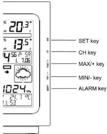
SET key
- Press and hold the key to enter manual setting modes: LCD contrast, 12/24 hour time display, time zone, manual time setting, calendar, DCF ON/OFF, °C/°F temperature unit, pressure unit, relative pressure value and language display
- Confirm key in outdoor temperature alarm setting mode
- Reset individual MIN/MAX temperature/humidity record
- Stop the outdoor temperature alarm ringing
CH key (Channel key)
- Select channel 1, 2, or 3 (if more than 1 transmitter is used)
- Exit setting mode
• Re-detect new transmitters signal for all channels - Stop the outdoor temperature alarm ringing
MAX/+ key
- Display MAX indoor and outdoor temperature and humidity records with time of recording
- Increase all values in manual setting modes
- Activate/deactivate the outdoor temperature alarm
- Increase the temperature alarm values
- Stop the outdoor temperature alarm ringing
- Press and hold the key for 4 seconds to reset all MIN/MAX records
MIN/- key
- Display MIN indoor and outdoor temperature and humidity records with time of recording
- Decrease all values in manual setting modes
- Activate/deactivate the outdoor temperature alarm
• Decrease the outdoor temperature alarm values - Stop the outdoor temperature alarm ringing
- Press and hold the key for 4 seconds to reset all MIN/MAX records
ALARM key
- Enter the outdoor temperature alarm setting mode
- Stop the outdoor temperature alarm ringing
LCD SCREEN
The LCD screen is split into 6 sections displaying the outdoor data, indoor data, time and date, weather forecast, air pressure information and “intelligent” weather information.
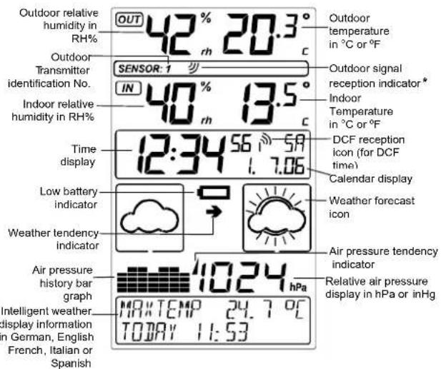
* When the signal form transmitter is successfully received by the Weather station, this signal reception icon will be switched on. (If not successful, the icon will not be shown in LCD) So user can easily see whether the last reception was successful (icon on) or not (icon off). On the other hand, the short blinking of the icon shows that a reception is being done at that time.
MANUAL SETTINGS:
The following manual settings can be changed when pressing and holding the SET key for approximately 3 seconds:
-
LCD contrast setting
• 12/24 hour time display -
Time zone setting
- Manual time setting
- Calendar setting
• DCF-77 time reception ON/OFF setting - °C/°F temperature unit setting
• Air pressure unit setting
• Relative pressure value setting
• Language display setting
LCD CONTRAST SETTING

The LCD contrast can be set within 8 levels, from LCD 1 to LCD8 (default setting is LCD 5):
- Press and hold the SET key for around 3 seconds until the digit start flashing.
- Use the MAX/+ or MIN/- key to view all levels of contrast.
- Select the desired LCD contrast. Confirm with the SET key and enter in the 12/24 Time Display setting.
12/24 HOUR TIME DISPLAY SETTING:

The time display can be set to view time as 12/24 hour format. The default time display mode is "24h". To set to "12h" time display:
- Use the MAX/+ or MIN/- key to toggle the value.
- Confirm with the SET key and enter the Time Zone setting.
TIME ZONE SETTING

The time zone can be set ±12 hour. The default time zone is set to "0h".
To set a different time zone:
- The current time zone value starts flashing.
- Use the MAX/+ or MIN/- key to set the time zone. The MAX/+ key increases the value and the MIN/- key decreases the value in consecutive 1 hour intervals.
- Confirm with the SET key and enter the Manual Time setting.
MANUAL TIME SETTING:
In case the Weather Station cannot detect the DCF-signal (for example due to disturbances, transmitting distance, etc.), the time can be manually set. The clock will then work as a normal Quartz clock.

- The hour digit will start flashing.
- Use the MAX/+ or MIN/- key to set the hour.
- Press again the SET key to switch to the minutes. The minute digits start flashing.
- Use the MAX/+ or MIN/- key to set the minutes.
- Confirm with the SET key and enter the Calendar setting.
Note:
The unit will still try to receive the signal between 2:00 and 6:00 am every day despite it being manually set, if the DCF reception function has been set ON. When it does receive the signal, it will change the manually set time into the received time. During reception attempts the DCF tower icon will flash. If reception has been unsuccessful, then the DCF tower icon will not appear but reception will still be attempted the following hour.
CALENDAR SETTING:
"Date. Month." (for 24h time display)
"Month. Date." (for 12h time display)
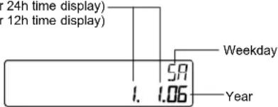
The date default of the Weather Station is 1.1. in the year 2005. Once the radio-controlled time signals are received, the date is automatically updated. However, if the signals are not received, the date can also be set manually.
- The year starts flashing.
- Use the MAX/+ or MIN/- key to set the year. The range runs from 2005 to 2030.
- Press the SET key again to confirm and to enter the month setting. The month starts flashing.
- Use the MAX/+ or MIN/- key to set the month.
- Press the SET key again to confirm and to enter the date setting mode. The date starts flashing.
- Use the MAX/+ or MIN/- key to set the date.
- Confirm all calendar settings with the SET key and enter the DCF Time Reception ON/OFF setting.
DCF TIME RECEPTION ON/OFF SETTING

In area where reception of the DCF time is not possible, the DCF time reception function can be turned OFF. The clock will then work as a normal Quartz clock. (Default setting is ON).
- The digit "ON" will start flashing on the LCD.
- Use the MAX/+ or MIN/- key to turn OFF the time reception function.
- Confirm with the SET key and enter the °C/°F Temperature Unit setting.
Note:
If the DCF time reception function is turned OFF manually, the clock will not perform any reception of the DCF time as long as the DCF OFF function is activated.
°C/°F TEMPERATURE UNIT SETTING

The temperature display can be selected to show temperature data in °C or °F. (default °C)
- Use the MAX/+ or MIN/- key to toggle between "°C" or "°F".
- Confirm with the SET key and enter the Air Pressure Unit setting.
RELATIVE AIR PRESSURE UNIT SETTING
The relative air pressure unit can be set in hPa or inHg. (default unit is in hPa).

- Use the MAX/+ or MIN/- key to toggle between "hPa" or "inHg".
- Confirm with the SET key and enter the Relative Pressure Value setting.
Note:
The default reference pressure value of the barometer is 1013 hPa. For an exact measurement it is necessary to first adjust the barometer to your local relative air pressure (related to elevation above sea level). Ask for the present atmospheric pressure of your home area (Local weather service, www, optician, calibrated instruments in public buildings, airport).
RELATIVE PRESSURE VALUE SETTING
The default relative pressure value is 1013 hPa (29.91 inHg). This corresponds to the average air pressure. Pressure below this is referred to as low-pressure area (weather to become worse), pressure above as high-pressure area (weather to improve). The relative air pressure can
be manually set to another value within the range of 960 – 1040 hPa (28.30 – 30.80 inHg) for a better reference.

- The current relative pressure value will start flashing
- Use the MAX/+ or MIN/- key to increase or decrease the value.
Keep holding the key allows the value to advance faster. - Confirm with the SET key and enter the Language display setting.
Note:
This calibration facility is useful for those users living at various elevations above sea level, but wanting their air pressure display based on sea level elevation.
LANGUAGE DISPLAY SETTING:
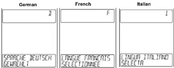
The language for the calendar and "Intelligent" weather information display can be set to view in German (D), French (F), Italian (I), Spanish (S) or English (E). To set the language:
- Use the MAX/+ or MIN/- key to select the desire language.
- Confirm with the SET key and exit the Manual settings.

TO EXIT THE MANUAL SETTING MODE
To exit the manual setting anytime from the manual setting modes, press the CH key anytime or wait for automatic timeout. The mode will return to normal display.
OUTDOOR TEMPERATURE ALARM SETTING
The "Intelligent" Weather Station enables the user to set the outdoor temperature upper and lower alarm for the outdoor channel No.1. The user set the alarm at the allowable range between -40 and 59.9°C. The high and low alarms can be switch on or off individually. For example, the user can set the thresholds (alarming temp) for the outdoor temperature to +40°C (high) and -10°C (low), whilst only switching on the high alarm and disabling the low alarm. In this setting, when the temperature is ≤ -10°C, the alarm will not sound; while temperature is ≥ 40°C, the alarm will sound.
| Default Outdoor alarming Temperature | Low alarm | 0°C |
| High alarm | 30°C |
LOW OUTDOOR TEMPERATURE ALARM SETTING
To set the LOW outdoor temperature alarm (default OFF):
- Press and hold the ALARM key for about 3 seconds to enter the alarm setting mode.

-
Press the MAX/+ or MIN/- key to activate the alarm ON or OFF.
-
Press the SET key to enter the alarm value setting (alarm value flashing)
-
Use the MAX/+ or MIN/- key to set the alarm value.
-
Press the SET key to confirm and enter the HIGH outdoor temperature alarm setting.
HIGH OUTDOOR TEMPERATURE ALARM SETTING
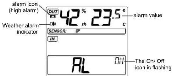
- The On/ Off icon is flashing. Press the MAX/+ or MIN/- key to activate the alarm ON/OFF.
- Press the SET key to enter the alarm value setting (alarm value flashing)
- Use the MAX/+ or MIN/- key to set the alarm value.
- Press the SET key to confirm and return to the normal display.
Note:
- The outdoor temperature alarm is only applicable to Channel 1. - The alarm icon " (outdoor high alarm) or " (outdoor low alarm) will be shown in normal display when the weather alarm is set ON.
When the alarming outdoor temperature is reached, the alarm will sound. The weather alarm indicator □□, high or low alarm icon and the temperature reading will be flashing on LCD. The alarm will sound for 120 seconds if no one stops the alarm.
User may press any key to stop the buzzer ringing. Then the weather alarm indicator, alarm icon and the temperature reading will be still flashing but the sound is stopped.
If the alarm key is not pressed, the weather alarm indicator will keep flashing, indicating that alarming temperature has been reached before. User may presses the Alarm key once to switch off the weather alarm indicator.
HYSTERESIS
To compensate for fluctuation of the measured data, which may cause the weather alarm to sound constantly if the measured reading is close to user set level, a hysteresis function has been implemented for each weather alarm. For example, if the high temperature alarm is set to +25^ and the current value moves to +25^ , the alarm will be activated (sounds). Now when the temperature drops to +24.9^ or below and thereafter again increases to beyond +25^ , the data will be blinking, but no alarm will be activated. It has to drop to below +24^ (with a pre-set hysteresis of 1^ ) so that the alarm can be produced again. Hysteresis values for the outdoor temperature alarm is set to be 1^ .
WEATHER FORECAST AND WEATHER TENDENCY:
WEATHER FORECASTING ICONS:
There are 4 weather icons in the fourth section of LCD which can be displayed in any of the following combinations:

Sunny
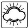
Cloudy with sunny intervals
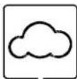
Cloudy

Rainy
For every sudden or significant change in the air pressure, the weather icons will be updated accordingly to represent the change in weather. If the icons do not change, then it means either the air pressure has not changed or the change has been too slow for the Weather station to register. However, if the icon displayed is a sun or rainy, there will be no change of icon if the weather gets any better (with sunny icon) or worse (with rainy icon) since the icons are already at their extremes.
The icons displayed forecasts the weather in terms of getting better or worse and not necessarily sunny or rainy as each icon indicates. For example, if the current weather is cloudy and the rainy icon is displayed, it does not mean that the product is faulty because it is not raining. It simply means that the air pressure has dropped and the weather is expected to get worse but not necessarily rainy.
The change of weather forecast icon is according to the relationship between current relative pressure and the pressure change since last three hours.
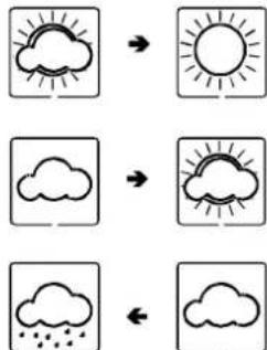
If the weather is changing, both old weather icon and new weather icon will be shown with weather tendency indicator (animated arrows). If the weather has not changed within 6 hours, only the new weather icon in the display will be shown.
Examples of changing weather icons:
flowchart
graph TD
    A["Sun with clouds"] --> B["Sunny with rays"]
    C["Cloud with rain cloud"] --> D["Cloud with rain cloud"]
    E["Rain cloud"] --> F["Cloud with rain cloud"]
Note:
After initial set up of the Intelligent Weather Station with the setting of the relative value, readings for weather forecasts should be disregarded for the next 12-24 hours. This will allow sufficient time for the Weather Station to collect air pressure data at a constant altitude and therefore result in a more accurate forecast.
If the Intelligent Weather Station is moved to another location significantly higher or lower than its initial standing point (for example from the ground floor to the upper floors of a house), set again the relative air pressure value, and discard the weather forecast for the next 12-24 hours. By doing this, the Weather Station will not mistake the new location as being a possible change in air-pressure when really it is due to the slight change of altitude.
AIR PRESSURE TENDENCY INDICATOR
The air pressure tendency indicator is located at the left side of the air pressure display, below the Weather icons, and it works independently from the Weather forecast icons. The air pressure tendency indicator pointing upward or downward directions is displayed based on comparing the difference of the air pressure recorded during a full hour time frame.

Air pressure tendency indicators
Note:
- An upward air pressure tendency indicator means that there is an increase in air pressure within the past 4 hours.
- A downward air pressure tendency indicator means that there is an decrease in air pressure within the past 4 hours.
AIR PRESSURE
The 5 ^th sections of the sections of the LCD show the relative air pressure and the air pressure history.
The reference relative air pressure (hPa) can be set between 960 to 1040hPa. See "Relative pressure value setting" in manual setting.
BAR GRAPH DISPLAY
Depending on programming conditions, display of the history of air pressure in form of a graph consisting of vertical bars.

AIR PRESSURE HISTORY
The bar graph of the electronic barometer shows the air pressure history of the past 12 hours in 7 steps.
The horizontal axis represents the last 12 hours air pressure recording
(-12, -9, -6, -3, -2, -1, and 0 hour). The bars are plotted at each of the 7 steps and give the trend over the recorded period. The scale on the right compares the result. The "0" in the middle of this scale determines the current air pressure.
The vertical axis represents the air pressure changes in hPa (+4.5, +3, +1.5, 0, -1.5, -3, -4.5. "0" represents the current air pressure). Each change (±1, ±2, ±3, ±4, ±5, ±6, ±7, ±8; the odd values are not shown on the vertical axis but can be determined) is shown in Hekto-Pascal (hPa). The past air pressure value was compared to the current one. If the bars are rising it indicates that the weather is getting better due to an increase in air pressure. If the bars go down it indicates a drop of the air pressure and the weather is expected to get worse from the present time "0".
At every full hour the current air pressure is used as a basis for the display of a new graph bar. The existing graph is then moved one bar to the left.
Note:
For accurate barometric pressure trend, the Intelligent Weather Station should operate at the same altitude. For example, it should not be moved from the ground to the second floor of the house. Should the unit be moved to a new location, discard readings for the next 12 – 36 hours.
INDOOR RELATIVE HUMIDITY AND INDOOR TEMPERATURE:
The indoor temperature and humidity data are automatically updated and displayed on the third of the LCD.
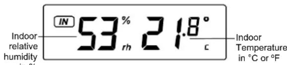
OUTDOOR TEMPERATURE AND HUMIDITY
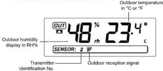
The first LCD section can show the outdoor temperature, the reception indicator, the minimum or maximum reading. A number in the bottom part will also be shown if more than one transmitter has been adopted.
TOGGLING BETWEEN MIN/MAX INDOOR AND OUTDOOR RECORDINGS:
To toggle between the current, minimum and maximum data and the times they were recorded, press the MIN/- key for viewing the minimum values, and press the MAX/+ key for viewing the maximum values (shown in MIN or Max displays).
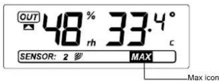
When pressing the MIN/- or the MAX/+ key, the MIN and the MAX data will be displayed as following sequences:
- MAX or MIN outdoor temperature data with time and date of recordings. Data will flash
-
MAX or MIN outdoor humidity data with time and date of recordings. Data will flash
-
MAX or MIN indoor temperature data with time and date of recordings. Data will flash
- MAX or MIN indoor humidity data with time and date of recordings. Data will flash
- Return to current indoor and outdoor data.
TO VIEW THE MIN/MAX DATA FROM DIFFERENT TRANSMITTERS When more than 1 transmitter used
- To toggle between transmitters, press the CH key:
Once to show transmitter 2
Twice to show transmitter 3
Three times to return to transmitter 1
- While the outdoor MIN/MAX humidity and temperature date is being displayed, press the CH key. The display will toggle between the different channels MIN/MAX data.
Note:
For example, when the MIN outdoor temperature data is displayed and the MAX/+ key is pressed, MAX data outdoor temperature will be displayed. If the MAX outdoor temperature data is displayed and the MIN/- key is pressed, MIN outdoor data will be displayed.
While MIN/MAX data is displayed, the channel can be changed by pressing the CH key.
TO RESET THE MIN/MAX VALUES TO CURRENT VALUES:
To reset the indoor and individual outdoor MIN/MAX values to current values:
- Press the MAX/+, MIN/- and CH key to select the desired MIN/MAX value.
- Press the SET key to reset the selected value to current value
Note:
To reset all indoor and outdoor MIN/MAX values to current values, press and hold the MAX/+ or MIN/- key for 3 seconds.
OUTDOOR CHANNEL RE-LEARN MODE
In case the temperature data in a particular outdoor channel often shows
"--." due to low battery level or false reset of a transmitter, then the
transmitters can be set up again. Then The "lost" channel can be re-learned again by entering the channel re-learn mode.
To relearn all the transmitters, press and hold the CH key for 3 seconds (outdoor reception signal will show again next to channel display).
Note:
All transmitters will be relevant at the same time.
LOW BATTERY INDICATOR
The low battery indicator will be displayed in the LCD when the battery power of the Intelligent Weather Station is low. It is recommended to replace the batteries in all units on an annual basis to ensure optimum accuracy of the Intelligent Weather Station.
Note: After battery change, both the Intelligent Weather Station and the transmitter(s) need to be reset (see note "Setting up")
"INTELLIGENT" WEATHER DISPLAY
The "Intelligent" Weather text display located at the last section of the LCD will display the weather forecast based on data received from channel 1 and the air pressure.
The weather station will automatically display the following information:
• Minimum temperature of the day
• Maximum temperature of the day
• Time frame for the weather forecast
• Probability of the weather forecast
• Probability of snowfall
- Probability of fog
• Probability of glazed frost
• Probability of tempest
• Probability of strong wind
- Probability of storm
- Forecast lowest night temperature (hit rate 65 % with a tolerance of +/- 2°C or 85 % with a tolerance of +/- 3°C)
Some examples of the intelligent weather display:
| German | English | French |
| VORHERSAGEIRUER12 STUNDEN | FORECAST PERIOD12 HOURS | PERIOD PREVISION12 HEURES |
| PROGNOSEINJEK 70°/o | FORECASTINJEK 70°/o | PREVISIONINJEK 70°/o |
| MAXTEMP 25.7 °CHEUTE 13:57 | MAXTEMP 25.7 °CTOJAY 13:57 | TEMPMAX 25.7 °CDU JOUR 13:57 |
| MINTEMP 23.7 °CHEUTE 3:57 | MINTEMP 23.7 °CTOJAY 3:57 | TEMPMIN 23.7 °CDU JOUR 3:57 |
| Italian | Spanish |
| DURATA PREV12 ORE | PERIODO PREV12 HORAS |
| INDICEPREVISIONE 70°/o | INDICEPREVISIONE 70°/o |
| TEMPMAX: 25.7 °COGGI 13:57 | TEMPMAX: 25.7 °CHOY 13:57 |
| TEMPMIN 23.7 °COGGI 3:57 | TEMPMIN 23.7 °CHOY 3:57 |
DETAILED INFORMATION SHOWN IN THE WEATHER DISPLAY:
| Displayed Information | |||||
| English German French Italian Spanish | |||||
| Time frame for weather forecast | Forecast period:6 hours /12 hours/24 hours/36 hours/48hours | Vorhersagedauer:6Stunden /12Stunden /24Stunden /36Stunden /48Stunden | Period prevision:6 heures/12heures /24heures /36heures /48heures | Durata prev.:6 ore/12 ore /24 ore /36 ore /48 ore | Periodo prev.:6 horas /12 horas /24 horas /36 horas /48 horas |
| Probability of weather forecast | Forecast Index:65% /70%/75% /80% /85% | Prognose Index:65% /70% /75% /80% /85% | Prévision Index:65% /70% /75% /80% /85% | Indice previsione : 65% /70% /75% /80% /85% | Indice prevision:65% /70% /75% /80% /85% |
| Maximum temp. of the day | MaxTemp xx.x°CTodayxx :xx | MaxTemp xx.x°CHeutexx :xx | Max Temp xx.x°CDu jour xx :xx | Temp max xx.x°CGggi: xx:xx | Temp max xx.x°C Hoy: xx:xx |
| Minimum temp. of the day | MinTemp xx.x°CTodayxx :xx | MinTemp xx.x°CHeutexx :xx | Min Temp xx.x°CDu jour xx :xx | Temp min xx.x°C Oggi xx:xx | Temp min xx.x°C Hoy xx:xx |
| Probability of snowfall | Snowfall Index:65% /75% | Schnee Index:65% /75% | Nelge Index:65% /75% | Indice neve:65% /75% | Indice nieve:65% /75% |
| Probability of fog | Fog Index:80% /85% | Nebal Index:80% /85% | Brouillard Index80% /85% | Indice nebbia:80% /85% | Indice niebla:80% /85% |
| Probability of glazed frost | Glazed frost Index 75% | Rauhreif Index 75% | Givre Index 75% | Indice brina: 75% | Indice escarcha: 75% |
| Probability of tempest | Tempest Index 80% | Gewitter Index 80% | Orage Index 80% | Indice temporal: 80% | Indice tormenta: 80% |
| Probability of strong winds | Strong wind Index 80% | Starkwind Index 80% | Vent Fort Index 80% | Indice vento forte: 80% | Indice viento forte: 80% |
| Probability of storm | Storm Index 75% | Sturm Index 75% | Tempête Index 75% | Indice tempesta: 75% | Indice tempestad: 75% |
| Forecast lowest night temp. | Forecast lowest nighttemp : xx °C | Min Erwartete nachtemp : xx °C | Prevision temp min nuit: xx °C | Previsione temp min notte: xx °C | Prevision temp min noche: xx °C |
The forecast period, forecast index and today maximum/minimum temperature will always be shown. Other information will be shown only when a specific weather event happened that has been calculated and forecast by the unique algorithm of the Intelligent Weather station.
OUTDOOR THERMO-HYGROTRANSMITTER/ 868MHZ RECEPTION CHECK
The outdoor temperature and humidity is measured and transmitted every 4.5 seconds.
The transmission range of the Outdoor Thermo-hygro transmitter may be affected by the ambient temperature. At cold temperatures the transmitting distance may be decreased. Please bear this in mind when placing the transmitter.
To install the Thermo-hygro transmitter outside, choose a shady and dry place. Before fixing the Thermo-hygro transmitter with the enclosed screws, wait for at least 5 minutes to see if the receiver is able to scan the signal from this location. Obstacles (walls, windows, trees) and interfering radio waves (PC, mobile phone, TV) can impede the reception or limit the range (about 100 meters in open space) considerably. Should interference occurred, choose
another location for the Thermo-hygro Transmitter and/or the Weather Station.
If the outdoor temperature and humidity data are not being received within few minutes after setting up (or the outdoor display show “--.” in the outdoor section of the Intelligent Weather Station). Please check the following points:
- The distance of the Weather Station or transmitter should be at least 1.5 to 2 meters away from any interfering sources such as computer monitors or TV sets.
- Avoid positioning the Weather Station onto or in the immediate proximity of metal doors or window frames.
- Using other electrical products such as headphones or speakers operating on the same signal frequency (868MHz) may prevent correct signal transmission and reception.
- Neighbours using electrical devices operating on the 868MHz signal frequency can also cause interference.
- "Visibility" of weather station and transmitter (e.g. through a window) increases the range.
Note:
When the 868MHz signal is received, do not re-open the battery cover of either the transmitter or Weather Station, as the batteries may spring free from the contacts and force a false reset. Should this happen accidentally then reset all units (see Setting up above) otherwise transmission problems may occur.
If no reception is possible despite the observation of these factors, all system units have to be reset (see Setting up).
POSITIONING THE WEATHER STATION:
The Weather Station has been designed to be hung onto wall or free standing.
To wall mount
Choose a sheltered place. Avoid direct rain and sunshine. Before wall mounting, please check that the outdoor temperature and humidity values can be received from the desired locations.
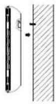
- Fix a screw (not supplied) into the desired wall, leaving the head extended out the by about 5mm.
- Remove the stand from the Weather Station by pulling it away from the base and hang the station onto the screw. Remember to ensure that it locks into place before releasing.
Free standing

With the detachable stand, the weather station can be placed onto any flat surface.
POSITIONING THE THERMO-HYGRO TRANSMITTER:

The Transmitter is supplied with a holder that may be attached to a wall with the two screws supplied. The Transmitter can also be position on a flat surface by securing the stand to the bottom to the Transmitter.
To wall mount:

-
Secure the bracket onto a desired wall using the screws and plastic anchors.
-
Clip the remote temperature/humidity sensor onto the bracket.
Note:
Before permanently fixing the transmitter wall base, place all units in the desired locations to check that the outdoor temperature and humidity readings are receivable. In event that the signal is not received, relocate the transmitters or move them slightly as this may help the signal reception.
CARE AND MAINTENANCE:
- Extreme temperatures, vibration and shock should be avoided as these may cause damage to the units and give inaccurate forecasts and readings.
- When cleaning the display and casings, use a soft damp cloth only. Do not use solvents or scouring agents as they may mark the LCD and casings.
- Do not submerge the units in water. Furthermore, fix all parts in place where the unit is adequately protected against moisture and rain.
- Immediately remove all low powered batteries to avoid leakage and damage. Replace only with new batteries of the recommended type.
- Do make any repair attempts to the units. Return it to their original point of purchase for repair by a qualified engineer. Opening and tampering with the units may invalidate their guarantee.
- Do not expose the units to extreme and sudden temperature changes, this may lead to rapid changes in forecasts and readings and thereby reduce their accuracy.
SPECIFICATIONS:
Temperature measuring range:
Indoor : 0°C to +59.9°C with 0.1°C resolution
32°F to +139.8°F with 0.2°F resolution
("OF.L" displayed if outside this range)
Outdoor : -39.9°C to +59.9°C with 0.1°C resolution
-39.8°F to +139.8°F with 0.2°F resolution
("OF.L" displayed if outside this range)
Relative humidity measuring range:
Indoor : 1% to 99% with 1% resolution
(- - " displayed when value < 1%; "99%"
displayed if value ≥ 99%)
Outdoor : 1% to 99% with 1% resolution
("1%" displayed when value ≤ 1%; "99%" is
played if value ≥ 99%)
Indoor temperature checking interval : every 20 seconds
Indoor humidity checking interval : every 20 seconds
Outdoor data reception : every 4.5 seconds
Air pressure checking interval : every 20 seconds
Transmission range : up to 100 meters (open space)
Power supply:
Weather Station : 3 x AA, IEC LR6, 1.5V
Thermo-hygro transmitter : 2 x AA, IEC LR6, 1.5V
Battery life cycle : approximately 12 months
(Alkaline batteries recommended)
Dimensions (L x W x H)
Weather Station : 120 x 31 x 175 mm (excluding stand)
Thermo-hygro transmitter : 43 x 23 x 160 mm (excluding stand)
LIABILITY DISCLAIMER
- The electrical and electronic wastes contain hazardous substances. Disposal of electronic waste in wild country and/or in unauthorized grounds strongly damages the environment.
- Please contact your local or/and regional authorities to retrieve the addresses of legal dumping grounds with selective collection.
• All electronic instruments must from now on be recycled. User
shall take an active part in the reuse, recycling and recovery of the electrical and electronic waste.
• The unrestricted disposal of electronic waste may do harm on public health and the quality of environment.
- As stated on the gift box and labeled on the product, reading the "User manual" is highly recommended for the benefit of the user. This product must however not be thrown in general rubbish collection points.
- The manufacturer and supplier cannot accept any responsibility for any incorrect readings and any consequences that occur should an inaccurate reading take place.
- This product is designed for use in the home only as indication of the temperature.
• This product is not to be used for medical purposes or for public information.
• The specifications of this product may change without prior notice.
• This product is not a toy. Keep out of the reach of children.
• No part of this manual may be reproduced without written authorization of the manufacturer.

R&TTE Directive 1999/5/EC
Summary of the Declaration of Conformity: We hereby declare that this wireless transmission device does comply with the essential requirements of R&TTE Directive 1999/5/EC.


- FEATURES:
- The Thermo-hygroTransmitter
- SETTING UP:
- When one transmitter is to be used
- When more than one transmitter is to be used
- HOW TO INSTALL AND REPLACE BATTERIES IN THE WEATHER STATION
- HOW TO INSTALL AND REPLACE BATTERIES IN THE OUTDOOR THERMO-HYGRO TRANSMITTER
- Note:
- BATTERY CHANGE:
- DCF-77 RADIO CONTROLLED TIME RECEPTION:
- FUNCTION KEYS:
- Weather Station:
- SET key
- CH key (Channel key)
- MAX/+ key
- MIN/- key
- ALARM key
- LCD SCREEN
- MANUAL SETTINGS:
- LCD CONTRAST SETTING
- 12/24 HOUR TIME DISPLAY SETTING:
- TIME ZONE SETTING
- MANUAL TIME SETTING:
- CALENDAR SETTING:
- DCF TIME RECEPTION ON/OFF SETTING
- °C/°F TEMPERATURE UNIT SETTING
- RELATIVE AIR PRESSURE UNIT SETTING
- RELATIVE PRESSURE VALUE SETTING
- LANGUAGE DISPLAY SETTING:
- TO EXIT THE MANUAL SETTING MODE
- OUTDOOR TEMPERATURE ALARM SETTING
- LOW OUTDOOR TEMPERATURE ALARM SETTING
- HYSTERESIS
- WEATHER FORECAST AND WEATHER TENDENCY:
- WEATHER FORECASTING ICONS:
- AIR PRESSURE TENDENCY INDICATOR
- AIR PRESSURE
- BAR GRAPH DISPLAY
- AIR PRESSURE HISTORY
- INDOOR RELATIVE HUMIDITY AND INDOOR TEMPERATURE:
- TOGGLING BETWEEN MIN/MAX INDOOR AND OUTDOOR RECORDINGS:
- TO VIEW THE MIN/MAX DATA FROM DIFFERENT TRANSMITTERS When more than 1 transmitter used
- TO RESET THE MIN/MAX VALUES TO CURRENT VALUES:
- OUTDOOR CHANNEL RE-LEARN MODE
- LOW BATTERY INDICATOR
- "INTELLIGENT" WEATHER DISPLAY
- OUTDOOR THERMO-HYGROTRANSMITTER/ 868MHZ RECEPTION CHECK
- another location for the Thermo-hygro Transmitter and/or the Weather Station.
- POSITIONING THE WEATHER STATION:
- To wall mount
- Free standing
- POSITIONING THE THERMO-HYGRO TRANSMITTER:
- CARE AND MAINTENANCE:
- SPECIFICATIONS:
- LIABILITY DISCLAIMER
- R&TTE Directive 1999/5/EC
Brand : TFA
Model : 35.1070.IT
Category : Weather Station