
SMART700DV - Uninterruptible power supply Tripp Lite - Free user manual and instructions
Find the device manual for free SMART700DV Tripp Lite in PDF.


| Product Type | Uninterruptible Power Supply (UPS) |
| Brand | Tripp Lite |
| Model | SMART700DV |
| Capacity | 700 VA / 420 W |
| Input Voltage | 230 V |
| Output Voltage | 230 V regulated |
| Number of Outlets | 6 IEC outlets |
| Battery Type | Sealed lead-acid, replaceable |
| Typical runtime (full load) | ~8 minutes |
| Recharge time | ~4 hours |
| Dimensions (L x W x H) | 295 x 135 x 200 mm |
| Weight | 9.5 kg |
| Protection | Protection against overvoltages and undervoltages |
| Voltage regulation (AVR) | Yes, automatic correction |
| EMI/RFI filtering | Yes |
| Display | LED indicators |
| Communication | USB/RS-232 port |
| Maintenance | Clean with a dry cloth |
| Safety | Do not open, battery contains hazardous substances |
| Recycling | Electronic device, battery to be recycled |
| Warranty | 2 years |
Frequently Asked Questions - SMART700DV Tripp Lite
User questions about SMART700DV Tripp Lite
0 question about this device. Answer the ones you know or ask your own.
Ask a new question about this device
Download the instructions for your Uninterruptible power supply in PDF format for free! Find your manual SMART700DV - Tripp Lite and take your electronic device back in hand. On this page are published all the documents necessary for the use of your device. SMART700DV by Tripp Lite.
USER MANUAL SMART700DV Tripp Lite
Intelligent, Line-Interactive UPS System
(Series Number: AGSM5436)
• 120V/230V Auto-Sensing Input, 120V Output
Not suitable for mobile applications.
Important Safety Instructions 2
Quick Installation 4
Optional Installation 5
Basic Operation 6
Battery Replacement 10
Storage and Service 10
Specifications 11
Product Registration 12
Regulatory Compliance 12
Español 13 • Français 25
WARRANTY REGISTRATION
Register your product today and be automatically entered to win an ISOBAR surge protector in our monthly drawing!
tripplite.com/warranty



Manufacturing Excellence.
SAVE THESE INSTRUCTIONS
This manual contains important instructions that should be followed during the installation, operation and storage of all Tripp Lite UPS Systems. Failure to heed these warnings will void your warranty.
UPS Location Warnings
• The UPS is heavy. Use caution when lifting it.
- Your UPS is intended to be used in a temperature/humidity controlled environment, indoor area that is relatively free of conductive contaminants. Install your UPS indoors, away from excess moisture, heat, conductive contaminants, dust and direct sunlight.
- For best performance, the ambient temperature near your UPS should be between 0^ and 40^ (between 32^ and 104^ ).
- Leave adequate space around all sides of the UPS for proper ventilation. Do not obstruct its vents or fan openings.
UPS Connection Warnings
- CAUTION: Install in accordance with National Electrical Code standards ANSI/NFPA 70 and Canadian Electrical Code, Part I, C22.1.
- Short-circuit backup protection and overcurrent protection is provided by the building installation.
- To reduce the risk of fire, connect only to a circuit-provided branch circuit overcurrent protection in accordance with the National Electrical Code, ANSI/NFPA 70 and the Canadian Electrical Code, Part I, C22.1. Be sure to use maximum 20A overcurrent protection, in accordance with the plug/equipment rating, for the installation.
- The plug on the power supply cord is intended to serve as the disconnect device. Be sure that the socket-outlet is installed near the equipment and is made easily accessible.
- The UPS contains its own energy source (battery). The output terminals may be live even when the UPS is not connected to an AC supply.
- Connect your UPS to a properly grounded AC power outlet. Do not modify the UPS's plug in a way that would eliminate the UPS's connection to ground. Do not use adapters that eliminate the UPS's connection to ground.
- Do not plug your UPS into itself; this will damage the UPS and void your warranty.
- If you are connecting your UPS to a motor-powered AC generator, the generator must provide filtered, frequency-regulated computer-grade output. Connecting your UPS to a generator will void its Ultimate Lifetime Insurance.
Equipment Connection Warnings
- Use of this equipment in life support applications where failure of this equipment can reasonably be expected to cause the failure of the life support equipment or to significantly affect its safety or effectiveness is not recommended.
- Do not connect surge protectors or extension cords to the output of your UPS. This might overload the UPS and will void the surge protector and UPS warranties.
Battery Warnings
- Batteries can present a risk of electrical shock and burn from high short-circuit current. Observe proper precautions. Do not dispose of the batteries in a fire. Do not open the UPS or batteries. Do not short or bridge the battery terminals with any object. Unplug and turn off the UPS before performing battery replacement. Use tools with insulated handles. There are no user-serviceable parts inside the UPS. Battery replacement should be performed only by authorized service personnel using the same number and type of batteries (Sealed Lead-Acid). The batteries are recyclable. Refer to your local codes for disposal requirements or visit tripplite.com/support/recycling-program for recycling information. Tripp Lite offers a complete line of UPS system Replacement Battery Cartridges (R.B.C.). Visit Tripp Lite at tripplite.com to locate the specific replacement battery for your UPS.
- During hot-swap battery replacement, the UPS will not provide backup power in the event of a blackout or other power interruptions.
- Do not operate UPS without batteries.
- Do not attempt to add external batteries to the UPS.
UPS and Battery Recycling

Pb
Please recycle Tripp Lite Products. The batteries used in Tripp Lite products are sealed Lead-Acid batteries. These batteries are highly recyclable. Please refer to your local codes for disposal requirements.
You can call Tripp Lite for recycling info at 773.869.1234.
You can go the Tripp Lite Website for up-to-date information on recycling the batteries or any Tripp Lite product. For more information, visit.triplite.com/en/support/recycling-program.cfm
Quick Installation
1 Plug the UPS into a wall outlet supplying 120V or 230V (nominal) AC power.
Use the included detachable power cord. The IEC-320 end connects to the AC input receptacle on the rear of the UPS. The NEMA 5-15 end connects to the wall outlet.
To plug the UPS into a wall outlet that does not accept a NEMA 5-15 plug, simply replace the included power cord with a detachable cord from another piece of equipment, such as a computer. Then, use the included power cord to connect the equipment to the UPS.
NOTE: After you plug the UPS into a live AC outlet, the UPS (in "Standby" mode) will automatically charge its batteries,* but will not supply power to its outlets until it is turned ON (see Step 3 below).
* The BATTERY CHARGE LED will be the only LED illuminated.
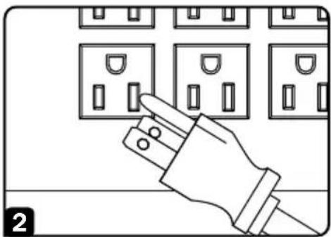
2 Plug your equipment into the UPS.
NOTE: Your UPS is designed to support only electronic equipment. You will overload the UPS if the total VA ratings for all the equipment you connect exceeds the UPS Output Capacity (700VA). To find your equipment's VA ratings, look on their nameplates. If the equipment is listed in amps, multiply the number of amps by 120 to determine VA.
(Example: 1 amp × 120 = 120 VA). If you are unsure if you have overloaded the UPS outlets, see "OUTPUT LOAD LEVEL" LED description.
3 Turn the UPS ON.
Press and hold the "ON/OFF/STANDBY" button for one second. The alarm will beep once briefly after one second has passed. Release the button.

natural_image
Illustration of a hand inserting a plug into an electrical socket (no text or symbols)
Optional Installation
These connections are optional. Your UPS will function properly without these connections.
1 USB and RS-232 Serial Communications
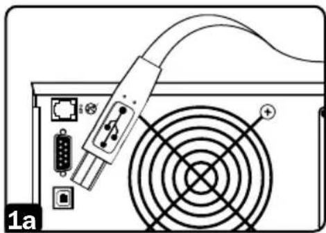
Use the included USB cable 1a and/or DB9 serial cable 1b to connect the communication port on your equipment to the communication port of your UPS. Install on your equipment the Tripp Lite PowerAlert® Software appropriate to your equipment's operating system. Consult your PowerAlert documentation for more information.
2 EPO Port Connection
This optional feature is only for those applications that require connection to a facility's Emergency Power Off (EPO) circuit. When the UPS is connected to this circuit, it enables emergency shutdown of the UPS inverter.
Using the cable provided, connect the EPO port of your UPS 2a to a user-supplied normally closed or normally open switch according to the circuit diagram 2b. The EPO port is not a phone line surge protector. Do not connect a phone line to this port.
natural_image
Diagram of a computer power adapter with cable and fan, showing ports and connection point (no text or symbols)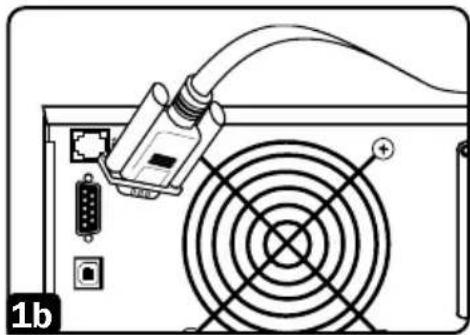
natural_image
Diagram of a computer power adapter with cable and fan blade (no text or symbols)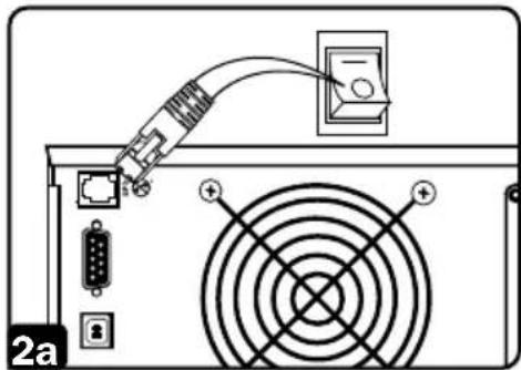
natural_image
Diagram of a computer power connector with an attached cable and fan (no text or symbols)
flowchart
graph TD
    A["OPTION 1: USER SUPPLIED NORMALLY CLOSED SWITCH"] --> B["4-5 JUMPER"]
    B --> C["N.C. EPO SWITCH"]
    D["OPTION 2: USER SUPPLIED NORMALLY OPEN SWITCH"] --> E["N.B. EPO SWITCH"]
    E --> F["N.C. EPO SWITCH"]
    G["BJ/11 PLUG"] --> H["NO CONNECTION"]
    I["BJ/11 PLUG"] --> J["NO CONNECTION"]
    K["5"] --> L["4"]
    M["4"] --> N["3"]
    O["2"] --> P["NO CONNECTION"]
Basic Operation
Buttons (Front Panel)

natural_image
Simple black circular icon of a power button symbol on white background (no text or labels)"ON/OFF/STANDBY" Button
- To turn the UPS ON: With the UPS plugged into a live AC wall outlet*, press and hold the “ON/OFF/STANDBY” button for one second.** Release the button. If utility power is absent, you can “cold-start” the UPS (i.e.: turn it ON and supply power for a limited time from its batteries***) by pressing and holding the “ON/OFF/STANDBY” button for one second.**
- To turn the UPS OFF: With the UPS ON and receiving utility power, press and hold the “ON/OFF/STANDBY” button for one second.** Then unplug the UPS from the wall outlet. The UPS will be completely OFF.
* After you plug the UPS into a live AC outlet, the UPS (in "Standby" mode) will automatically charge its batteries, but will not supply power to its outlets until it is turned ON. ** The alarm will beep once briefly after the indicated interval has passed. *** If fully charged.
natural_image
Speaker icon with sound waves, no text or symbols present"MUTE/TEST" Button
To Silence (or "Mute") UPS Alarms: Briefly press and release the MUTE/TEST button.*
To Run a Self-Test: With your UPS plugged in and turned ON, press and hold the MUTE/TEST button for two seconds.* Continue holding the button until the alarm beeps several times and the UPS performs a self-test. See “Results of a Self-Test” below. You can leave connected equipment on during a self-test. Your UPS, however, will not perform a self-test if the UPS is not turned on (see “ON/OFF/STANDBY” Button description).
CAUTION! Do not unplug your UPS to test its batteries. This will remove safe electrical grounding and may introduce a damaging surge into your network connections.
Results of a Self-Test: The test will last approximately 10 seconds as the UPS switches to battery to test its load capacity and battery charge.
- If the “OUTPUT LOAD LEVEL” LED remains illuminated red and the alarm continues to sound after the test, the UPS outlets are overloaded. To clear the overload, unplug some of your equipment and run the self-test repeatedly until the “OUTPUT LOAD LEVEL” LED no longer illuminates red and the alarm no longer sounds.
CAUTION! Any overload that is not corrected by the user immediately following a self-test may cause the UPS to shut down and cease supplying output power in the event of a blackout or brownout.
Basic Operation
- If the “BATTERY WARNING” LED illuminates and the alarm continues to sound after the test, the UPS batteries need to be recharged or replaced. Allow the UPS to recharge continuously for 12 hours and repeat the self-test. If the LED remains illuminated, contact Tripp Lite for service. If your UPS requires battery replacement, visit tripplite.com to locate the specific Tripp Lite replacement battery for your UPS.
* The alarm will beep once briefly after the indicated interval has passed.
Indicator Lights (Front Panel)
All Indicator Light descriptions apply when the UPS is plugged into a wall outlet and turned ON.
natural_image
Simple wavy line inside a square frame (no text or symbols)"POWER" LED: This green LED illuminates continuously when the UPS is ON and supplying connected equipment with AC power from a utility source. The LED flashes and an alarm sounds (4 short beeps followed by a pause) to indicate the UPS is operating from its internal batteries during a blackout or severe brownout. If the blackout or severe brownout is prolonged, you should save files and shut down your equipment since internal battery power will eventually be depleted. See "BATTERY CHARGE" LED description below.

natural_image
Simple wavy line diagram with double-headed arrow inside a rounded square (no text or symbols)"VOLTAGE CORRECTION" LED: This green LED illuminates continuously whenever the UPS is automatically correcting high or low AC voltage on the utility line without the assistance of battery power. The UPS will also emit a slight clicking noise. These are normal, automatic operations of the UPS. No action is required on your part.
natural_image
Simple diagram of a seesaw with two dots on one side and a triangular base (no text or symbols)"OUTPUT LOAD LEVEL" LED: This multicolored LED indicates the approximate electrical load of equipment connected to the UPS AC outlets. It will turn from green (light load) to yellow (medium load) to red (overload). If the LED is red (either illuminated continuously or flashing), clear the overload immediately by unplugging some of your equipment from the outlets until the LED changes from red to yellow (or green). CAUTION! Any overload that is not corrected by the user immediately may cause the UPS to shut down and cease supplying output power in the event of a blackout or brownout.
Basic Operation
natural_image
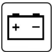
Simple battery icon with plus and minus signs, no text or symbols present"BATTERY CHARGE" LED: When the UPS is operating from utility power, this LED indicates the approximate charge state of the UPS internal batteries: red indicates the batteries are beginning to charge; yellow indicates the batteries are roughly midway through charging; and green indicates the batteries are fully charged. When the UPS is operating from battery power during a blackout or severe brownout, this LED indicates the approximate amount of energy (ultimately affecting runtime) which the UPS batteries will provide: red indicates a low level of energy; yellow indicates a medium level of energy; and green indicates a high level of energy. Since the runtime performance of all UPS batteries will gradually deplete over time, it is recommended that you periodically perform a self-test (see MUTE/TEST Button description) to determine the energy level of your UPS batteries BEFORE a blackout or severe brownout occurs. During a prolonged blackout or severe brownout, you should save files and shut down your equipment since battery power will eventually be depleted. When the LED turns red and an alarm sounds continuously, it indicates the UPS batteries are nearly out of power and UPS shutdown is imminent.
natural_image
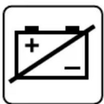
Simple battery icon with a diagonal line and plus/minus symbols, no text or numbers present."BATTERY WARNING" LED: This LED illuminates red and an alarm sounds intermittently after you initiate a self test (see "MUTE/TEST" Button description) to indicate the UPS batteries need to be recharged or replaced. Allow the UPS to recharge continuously for 12 hours, and repeat the self-test. If the LED continues to illuminate, contact Tripp Lite for service. If your UPS requires battery replacement, visit triplite.com to locate the specific Tripp Lite replacement battery for your UPS.
Other UPS Features (Rear Panel)
natural_image
Simple line drawing of two vertical rectangular panels above a semicircular arch (no text or symbols)15 amp/120V
NEMA 5-15R
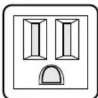
AC Receptacles: Your UPS features 15-amp AC outlets. These output receptacles provide your connected equipment with AC line power during normal operation and battery power during blackouts and brownouts. The UPS protects equipment connected to these receptacles against damaging surges and line noise. If you have a serial or USB connection to your UPS, you can remotely reboot connected equipment by turning the receptacles OFF and ON using Tripp Lite's PowerAlert Software.

natural_image
Simple line drawing of a four-pin electrical connector (no text or symbols)
Communications Ports (USB or RS-232): These ports connect your UPS to any workstation or server. Use with Tripp Lite's PowerAlert Software and included cables to enable your computer to automatically save open files and shut down equipment during a blackout. Also use PowerAlert Software to monitor a wide variety of AC line power and UPS operating conditions. Consult your PowerAlert Software documentation or contact Tripp Lite Customer Support for more information. See “USB and RS-232 Serial Communications” in the “Optional Installation” section for installation instructions.
Basic Operation
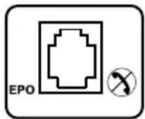
EPO (Emergency Power Off) Port: Your UPS features a EPO port that may be used to connect the UPS to a contact closure switch to enable emergency inverter shutdown. See the “Optional Installation” section for more information.

natural_image
Simple line drawing of a rectangular object with two circular ends and a plus sign, enclosed in a rounded square border (no text or symbols)Accessory Slot: Remove the small cover panel from this slot to install optional accessories to remotely monitor and control your UPS. Refer to your accessory's manual for installation instructions. Contact Tripp Lite Customer Support at 773.869.1234 for more information, including a list of available SNMP, network management and connectivity products.
natural_image
Simple geometric diagram with concentric circles inside a square frame (no text or symbols)Input Breaker: Protect your electrical circuit from overcurrent draw from the UPS load. If this breaker trips, remove some of the load, then reset it by pressing the breaker in.
Battery Replacement
Under normal conditions, the original batteries in your UPS will last many years. See the “Safety” section before replacing batteries. The batteries are designed for hot-swap replacement (i.e. leaving the UPS in ON mode), but some qualified service personnel may wish to put the UPS in the OFF mode and disconnect equipment before proceeding.
Procedure

1 Remove Front Panel
2 Disconnect Batteries
3 Remove/Dispose of Batteries
4 Add New Batteries
5 Connect Batteries
Attach connectors: black-to-black and red-to-red.
6 Replace Front Panel
Storage and Service
Storage
Before storing your UPS, turn it completely OFF: with the UPS ON and receiving utility power, press and hold the “ON/OFF/STANDBY” button for one second (an alarm will beep once briefly after the interval has passed); then, unplug the UPS from the wall outlet. If you store your UPS for an extended period of time, recharge the UPS batteries once every three months: plug the UPS into a wall outlet; allow it to charge for 12 hours; then unplug it and place it back in storage.
Note: After you plug the UPS in, it will automatically begin charging its batteries. However, it will not supply power to its outlets (see Quick Installation section). If you leave your UPS batteries discharged for an extended period of time, they will suffer a permanent loss of capacity.
Storage and Service
Service
A variety of Extended Warranty and On-Site Service Programs are also available from Tripp Lite. For more information on service, visit tripplite.com/support. Before returning your product for service, follow these steps:
- Review the installation and operation procedures in this manual to ensure that the service problem does not originate from a misreading of the instructions.
- If the problem continues, do not contact or return the product to the dealer. Instead, visit tripplite.com/support.
- If the problem requires service, visit tripplite.com/support and click the Product Returns link. From here you can request a Returned Material Authorization (RMA) number, which is required for service. This simple online form will ask for your unit's model and serial numbers, along with other general purchaser information. The RMA number, along with shipping instructions, will be e-mailed to you. Any damages (direct, indirect, special or consequential) to the product incurred during shipment to Tripp Lite or an authorized Tripp Lite service center is not covered under warranty. Products shipped to Tripp Lite or an authorized Tripp Lite service center must have transportation charges prepaid. Mark the RMA number on the outside of the package. If the product is within its warranty period, enclose a copy of your sales receipt. Return the product for service using an insured carrier to the address given to you when you request the RMA.
Specifications
| Model: SMART700DV |
| Input Voltage: 120V or 230V AC (nominal), auto-sensing |
| Input Frequency: 50 or 60 Hz, auto-sensing |
| Input Receptacle: IEC-320-C14 (Accepts detachable power cords. Included cord features NEMA 5-15 plug.) |
| Output Voltage: 120V AC |
| Output Frequency: 50 or 60 Hz |
| Output Capacity (VA): 700 |
| Output Capacity (Watts): 450 |
| Output Receptacles: 6 NEMA 5-15R |
| Communications Ports: 1 USB, 1 RS-232 |
| Emergency Power Off (EPO) Port: 1 |
Product Registration
Visit tripplite.com/warranty today to register your new Tripp Lite product. You'll be automatically entered into a drawing for a chance to win a FREE Tripp Lite product!*
* No purchase necessary. Void where prohibited. Some restrictions apply. See website for details.
Regulatory Compliance
FCC Notice, Class A
This device complies with part 15 of the FCC Rules. Operation is subject to the following two conditions: (1) This device may not cause harmful interference, and (2) this device must accept any interference received, including interference that may cause undesired operation.
Note: This equipment has been tested and found to comply with the limits for a Class A digital device, pursuant to part 15 of the FCC Rules. These limits are designed to provide reasonable protection against harmful interference when the equipment is operated in a commercial environment. This equipment generates, uses, and can radiate radio frequency energy and, if not installed and used in accordance with the instruction manual, may cause harmful interference to radio communications. Operation of this equipment in a residential area is likely to cause harmful interference in which case the user will be required to correct the interference at his own expense. The user must use shielded cables and connectors with this equipment. Any changes or modifications to this equipment not expressly approved by Tripp Lite could void the user's authority to operate this equipment.
Regulatory Compliance Identification Numbers
For the purpose of regulatory compliance certifications and identification, your Tripp Lite product has been assigned a unique series number. The series number can be found on the product nameplate label, along with all required approval markings and information. When requesting compliance information for this product, always refer to the series number. The series number should not be confused with the marketing name or model number of the product.
WEEE Compliance Information for Tripp Lite Customers and Recyclers (European Union)

Under the Waste Electrical and Electronic Equipment (WEEE) Directive and implementing regulations, when customers buy new electrical and electronic equipment from Tripp Lite they are entitled to:
- Send old equipment for recycling on a one-for-one, like-for-like basis (this varies depending on the country)
- Send the new equipment back for recycling when this ultimately becomes waste
Tripp Lite has a policy of continuous improvement. Specifications are subject to change without notice. Photos and illustrations may differ slightly from actual products.
Note on Labeling
Two symbols are used on the label.
V\~ : AC Voltage
V÷DC Voltage


1111 W. 35th Street, Chicago, IL 60609 USA • tripplite.com/support

natural_image
Illustration of a hand inserting a plug into an electrical outlet (no text or symbols)
natural_image
Diagram of a computer power adapter with cable and fan, showing ports and connection points (no text or symbols)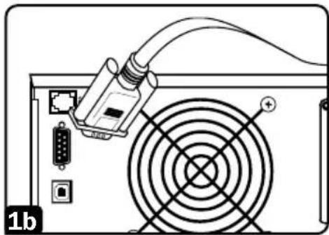
natural_image
Diagram of a computer power adapter with cable and fan blade (no text or symbols)natural_image
Diagram of a computer power connector with circuit board and fan (no text or symbols)
flowchart
graph TD
    A["OPTION 1: USER SUPPLIED NORMALLY CLOSED SWITCH"] --> B["4-5 JUMPER"]
    B --> C["N.C. EPO SWITCH"]
    D["OPTION 2: USER SUPPLIED NORMALLY OPEN SWITCH"] --> E["N.D. EPO SWITCH"]
    E --> F["N.C. EPO SWITCH"]
    G["RJ/11 PLUG"] --> H["NO CONNECTION"]
    I["RJ/11 PLUG"] --> J["NO CONNECTION"]
    H --> K["5"]
    J --> L["3"]
    K --> M["4"]
    L --> N["2"]
    M --> O["4"]
    N --> P["2"]
Operación Básica
Botones (Panel Frontal)

natural_image
Simple black circular icon of a power button symbol on white background (no text or labels)natural_image
Speaker icon with sound waves, no text or symbols presentnatural_image
Simple wavy line inside a square frame (no text or symbols)natural_image
Simple diagram of a seesaw with two circles on one side and a triangle on the other (no text or symbols)natural_image
Simple battery icon with plus and minus signs, no text or symbols presentnatural_image
Simple battery icon with a diagonal line and plus/minus symbols, no text or numbers present.natural_image
Simple line drawing of two vertical rectangular panels above a semi-circular arch (no text or symbols)natural_image
Simple line drawing of a four-pin electrical connector (no text or symbols)
natural_image
Simple line drawing of a rectangular object with two circular ends and a plus sign, enclosed in a rounded square border (no text or symbols)natural_image
Simple geometric diagram with concentric circles inside a square frame (no text or symbols)
natural_image
Illustration of a hand inserting a plug into an electrical panel (no text or symbols)
natural_image
Diagram of a computer power adapter with cable and fan, showing ports and connection points (no text or symbols)
natural_image
Diagram of a computer power adapter with cable and fan blade (no text or symbols)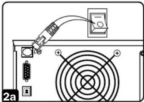
natural_image
Diagram of a computer power connector with an attached cable and fan (no text or symbols)
flowchart
graph TD
    A["OPTION 1: USER SUPPLIED NORMALLY CLOSED SWITCH"] --> B["4-S JUMPER"]
    B --> C["N.C. EPO SWITCH"]
    D["RJ/11 PLUG"] --> E["NO CONNECTION"]
    F["RJ/11 PLUG"] --> G["NO CONNECTION"]
    H["OPTION 2: USER SUPPLIED NORMALLY OPEN SWITCH"] --> I["N.B. EPO SWITCH"]
    I --> J["NO CONNECTION"]
    K["OPTION 2: USER SUPPLIED NORMALLY OPEN SWITCH"] --> L["NO CONNECTION"]
    M["OPTION 2: USER SUPPLIED NORMALLY OPEN SWITCH"] --> N["NO CONNECTION"]
natural_image
Simple black-and-white icon of a power button (no text or symbols)natural_image
Speaker icon with sound waves, no text or symbols presentnatural_image
Simple wavy line inside a square frame (no text or symbols)natural_image
Simple diagram of a seesaw with two circles on one side and a triangle on the other (no text or symbols)natural_image
Simple battery icon with plus and minus signs, no text or symbols presentnatural_image
Simple battery icon with a diagonal line and plus/minus symbols, no text or numbers present.natural_image
Simple line drawing of two vertical rectangular shapes above a curved arch (no text or symbols)natural_image
Simple line drawing of a four-pin electrical connector (no text or symbols)
natural_image
Simple line drawing of a rectangular shape with two circular ends and a plus symbol at the bottom (no text or labels)natural_image
Simple geometric diagram with concentric circles inside a square frame (no text or symbols)1111 W. 35th Street, Chicago, IL 60609 USA • tripplite.com/support


- Intelligent, Line-Interactive UPS System
- WARRANTY REGISTRATION
- SAVE THESE INSTRUCTIONS
- UPS Location Warnings
- UPS Connection Warnings
- Equipment Connection Warnings
- Battery Warnings
- UPS and Battery Recycling
- Quick Installation
- Plug the UPS into a wall outlet supplying 120V or 230V (nominal) AC power.
- Plug your equipment into the UPS.
- Turn the UPS ON.
- Optional Installation
- USB and RS-232 Serial Communications
- EPO Port Connection
- Basic Operation
- Buttons (Front Panel)
- "ON/OFF/STANDBY" Button
- "MUTE/TEST" Button
- CAUTION! Do not unplug your UPS to test its batteries. This will remove safe electrical grounding and may introduce a damaging surge into your network connections.
- Indicator Lights (Front Panel)
- Other UPS Features (Rear Panel)
- Battery Replacement
- Procedure
- Storage and Service
- Storage
- Service
- Specifications
- Product Registration
- Regulatory Compliance
- FCC Notice, Class A
- WEEE Compliance Information for Tripp Lite Customers and Recyclers (European Union)
- Note on Labeling
- Operación Básica
- Botones (Panel Frontal)
Brand : Tripp Lite
Model : SMART700DV
Category : Uninterruptible power supply