
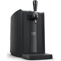
PerfectDraft HD3610 - Beer dispenser PHILIPS - Free user manual and instructions
Find the device manual for free PerfectDraft HD3610 PHILIPS in PDF.


| Product type | Beer dispenser |
| Brand | Philips |
| Model | PerfectDraft HD3610 |
| Capacity | Compatibility with 6 L PerfectDraft kegs |
| Dimensions (L x W x H) | Approximately 25 x 30 x 40 cm |
| Weight | Approximately 5.2 kg |
| Power supply | 220-240 V, 50/60 Hz |
| Power consumption | 75 W (maximum) |
| Cooling type | Thermoelectric |
| Operating temperature | 3 to 5 °C |
| Main features | Automatic pressurization, adjustable drip tray, LED temperature indicator |
| Tank material | Stainless steel and ABS plastic |
| Cleaning and maintenance | Circuit cleaning after each keg, descaling every 3 months |
| Safety | Automatic shut-off in case of overheating, keg locking handle |
| Available spare parts | Hose, pouring spout, gasket, drip tray |
| Repairability | Repairability index of 6.2/10 |
| Warranty | 2 years |
Frequently Asked Questions - PerfectDraft HD3610 PHILIPS
User questions about PerfectDraft HD3610 PHILIPS
0 question about this device. Answer the ones you know or ask your own.
Ask a new question about this device
Download the instructions for your Beer dispenser in PDF format for free! Find your manual PerfectDraft HD3610 - PHILIPS and take your electronic device back in hand. On this page are published all the documents necessary for the use of your device. PerfectDraft HD3610 by PHILIPS.
USER MANUAL PerfectDraft HD3610 PHILIPS
natural_image
Black Philips PerfectDraft water dispenser with digital display and lever handle (no text or symbols on device body)
natural_image
Black Philips PerfectDraft water dispenser with black handle and white base (no text or symbols on device body)
1
ENGLISH 6
DEUTSCH 25
Congratulations on purchasing this new PerfectDraft. From now on you can enjoy the perfect taste of fresh, cold draft beer. The system keeps your beer fresh and at exactly the right temperature so that you can pour a cold beer whenever you feel like it. Several beer brands are available for this system. You can find the beer brands available in your country on the box of the PerfectDraft system (also see chapter ‘Keg suppliers’ at the end of user manual). You can visit our website at www.perfectdraft.com for more information.
This user manual tells you how to use the PerfectDraft.
Because the name of this appliance is PerfectDraft, we use 'draft beer' instead of 'draught beer' in this user manual.
General description (Fig. 1)
A Right door
B Release button
C Cooling plate
D Cord storage facility
E LCD display: beer temperature, beer level & freshness indication (HD3620 only)
F Keg sensor
G Temperature sensor
H Left door
Locking levers
J LED indicator lights to indicate the status of the appliance (HD3610 only)
K Drip tray cover (HD3620)
L Drip tray (HD3620)
M Drip tray cover (HD3610)
N Drip tray (HD3610)
Tube unit (supplied with keg)
Tube connector
P Tube
Tap unit
Q Medallion
R Tap handle
S Tap body
T Spout
U Release buttons
v Tube release button
Keg
W Connection top
X Protection cap
Y Chimes
Important
Read this user manual carefully before you use the appliance and save it for future reference.
The appliance
Warning
- If the mains cord is damaged, you must have it replaced by Philips, a service centre authorised by Philips or similarly qualified persons in order to avoid a hazard.
- Check if the voltage indicated on the bottom of the appliance corresponds to the local mains voltage before you connect the appliance.
- Do not use the appliance if the plug, the cord or the appliance itself is damaged.
- This appliance is not intended for use by persons (including children) with reduced physical, sensory or mental capabilities, or lack of experience and knowledge, unless they have been given supervision or instruction concerning use of the appliance by a person responsible for their safety.
- Children should be supervised to ensure that they do not play with the appliance.
- Do not cover the appliance (e.g. with a towel) to prevent it from overheating.
- This appliance is only intended for indoor use. Do not use it outdoors.
- The appliance is not suitable for installation in an area where a water jet could be used.
Caution
- Keep the appliance out of the reach of children. The handle can be removed for extra safety.
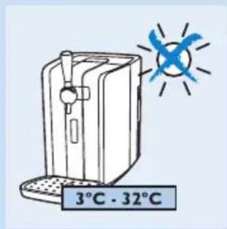
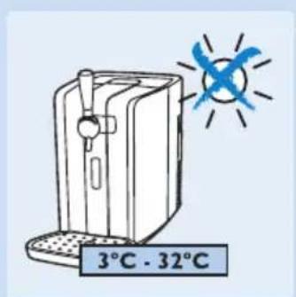
- Put the appliance on a horizontal, even and stable surface. Leave at least 10cm free space around the appliance for the best performance.
- In an environment with an ambient temperature of 23^ C, it takes approximately 12 to 15 hours to chill an uncooled keg to the ideal drinking temperature of 3^ C. At higher ambient temperatures, chilling the keg takes longer.
- When you use the appliance above 32^ C (HD3620) or 30^ C (HD3610), the beer temperature may rise above 3^ C. When the temperature decreases to below 32^ C, the beer temperature drops to 3^ C again.
- Do not expose the appliance to direct sunlight.
- Always clean the appliance before you store it for a longer period. Make sure you rinse the tap unit thoroughly. Beer residues may cause problems when you install the tap unit on the keg.
- Do not lift the appliance by the tap handle.

natural_image
Diagram of a robotic arm with a blue arrow indicating upward motion (no text or symbols)
The keg
Warning
- Never store the keg in the freezer! Freezing may cause serious damage to the keg.


- To avoid the risk of explosion, do not expose the keg to direct sunlight or temperatures higher than 30^ C.
- The keg is under pressure. Do not remove the connection top or pierce the keg with a sharp object.
Caution
- Always read and follow the instructions and safety warnings on the keg before you install it in the appliance.
- Do not shake the keg.
- Store an open keg at the right temperature by leaving it in the appliance. Make sure the appliance is switched on. If you switch off the appliance because you are not going to use it for a longer period (e.g. a holiday), always remove the open keg from the appliance and put it in the fridge. Once a keg has been opened, the beer stays fresh for 30 days.
- Always check the expiry date on the keg when you buy it and before you install it.
- Do not use the keg if the connection top is damaged. If the connection top is damaged, the tap unit does not fit onto it.
- Unopened kegs keep best when you store them at a stable temperature. The cooler you store the keg, the better.
- Maximum working pressure: 1.5 bar.
- Use the keg only for the HD3620/HD3610/HD3600 PerfectDraft. Do not connect other equipment to the keg.
- Do not use kegs from other suppliers than the ones mentioned in this user manual (see chapter 'Keg suppliers').
- Do not use damaged kegs in this appliance, as this could harm the appliance. Return a damaged keg immediately to the shop where you bought it.
- The kegs are not stackable.
Electromagnetic fields (EMF)
This Philips appliance complies with all standards regarding electromagnetic fields (EMF). If handled properly and according to the instructions in this user manual, the appliance is safe to use based on scientific evidence available today.
Before first use
Installing the appliance
1 Put the appliance on a horizontal, even and stable surface. Leave at least 10cm free space around the appliance for the best performance.
Note: Do not put the appliance in a place where it is exposed to direct sunlight or to high temperatures (e.g. close to a cooker or an oven).

natural_image
Diagram of a heat exchanger with airflow direction indicated by blue arrows (no text or symbols)2 To store excess cord, push it into the storage compartment at the back of the appliance.
3 Insert the plug into the wall socket.

natural_image
Illustration of a remote control with a blue arrow pointing to the button (no text or symbols)4 HD3620: install the drip tray.

natural_image
Illustration of a door handle next to a grid-patterned device with a blue arrow pointing to it (no text or symbols)5 HD3610: install the drip tray.

natural_image
Diagram of a hand valve with a blue arrow indicating downward motion (no text or symbols)6 Attach the tap handle.

natural_image
Illustration of a hand pressing a small mechanical component with a blue arrow indicating downward motion (no text or symbols)7 Place the preferred medallion on top of the handle.
Preparing for use
Placing the tap unit onto the keg
Always clean the tap unit with water and, if necessary, with some washing-up liquid before you place it on the keg and insert the tube.

natural_image
Diagram of two mechanical components with directional arrows indicating rotation or movement (no text or symbols)1 Remove the protection cap and the tube from the keg.

2 If present, remove the tube connector and the tube from the tap unit. Hold the tap unit under a running tap and rinse the tube-connection hole (1) and the connection to the body of the appliance (2). If necessary, use some washing-up liquid.

natural_image
Illustration of a hand operating a kitchen sink with faucet and valve (no text or symbols)3 Then turn the tap unit upside down and rinse the keg connection in the bottom of the tap unit.
It is essential that all rubber parts of the tap unit are moist before you assemble the tap unit onto the keg.

natural_image
Diagram showing a hand operating a mechanical component with directional arrows indicating motion (no text or symbols present)4 Check if the tube release button works properly. When you press the blue tube release button, the two clamps in the opening have to move.
Note: If the clamps fail to move when you press the blue tube release button, rinse the tube-connection hole under a running tap again.

5 Put the tap unit onto the connection top of the keg by pushing it down firmly ('click').
When you assemble the tap unit properly, you hear two clicks in quick succession.
Tip: If you can move the arm of the connection top freely up and down, the tap unit is placed properly on the keg.

6 Make sure the release buttons on either side of the tap unit stick out equally far on both sides. If this is not the case, press the release buttons on both sides with your thumbs until you hear one click or two clicks in quick succession.
Placing the tube into the tap unit
natural_image
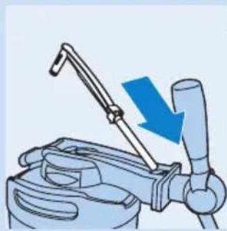
Illustration of a hand using a tool to lift a mechanical component, with a blue arrow indicating force direction (no text or symbols)1 Insert the flexible tube into the tap body.

natural_image
Illustration of a hand pump mechanism with a blue arrow indicating direction (no text or symbols)2 Slide the projections of the tube connector under the hinge points.
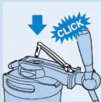
3 Push the tube connector into the opening in the tap unit ('click').
Placing the keg into the appliance
Never place the keg into the appliance if you have not assembled the tap unit and the tube properly. See sections 'Placing the tap unit onto the keg' and 'Placing the tube into the tap unit' in this chapter.

natural_image
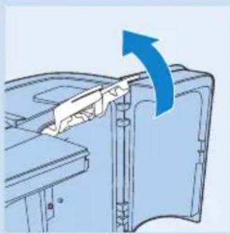
Illustration of a blue mechanical device with a blue arrow indicating direction (no text or symbols)1 Slide the release button to the right to open the doors.
natural_image
Diagram of a mechanical assembly with a blue arrow indicating direction (no text or symbols present)2 Lift the two blue locking levers completely.

natural_image
Mechanical assembly diagram showing piston and housing components with a blue arrow indicating motion (no text or labels)3 Tilt the keg with the assembled tap unit slightly forward and put it into the appliance.
- First put the keg on the cooling plate of the appliance.
- Then put the keg upright by sliding the tap unit between the blue locking levers.

natural_image
Mechanical assembly diagram showing a piston and lever mechanism with a blue arrow indicating rotation (no text or symbols present)4 Push down the blue locking levers until they are in horizontal position.
If you are unable to put the locking levers in horizontal position, you have not put the keg into the appliance in the right position. Take out the keg and follow steps 1 to 3 again.
After you have installed the keg (even the first time), the pump runs for a few seconds.

natural_image
Illustration of a mechanical device with blue directional arrows indicating motion or flow (no text or symbols)5 Close the doors.
Note: If the pump goes on frequently when you are not pouring beer, reinstall the keg or repeat the instructions in section 'Placing the tap unit onto the keg' in this chapter.
Cooling
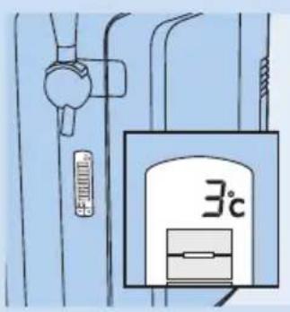
After you have installed the keg, the appliance automatically starts to cool the keg.
Note: At an ambient temperature of 23^ C, chilling an uncooled keg takes 12-15 hours.
Tip: If you want to pour beer shortly after placing the keg in the appliance, prechill the keg in upright position in the fridge for a while before you install it. For more tips, see chapter 'Troubleshooting'.
1 Wait until the beer has reached the right drinking temperature.
HD3620: The temperature is shown on the display in green (see section 'LCD display' in this chapter).
HD3610: The temperature light lights up green (see section 'LED indicator lights' in this chapter).

natural_image
Diagram of a battery and indicator light with three labeled components (no text or symbols)LCD display (HD3620 only)
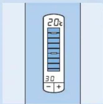
The display shows the temperature of the beer, the beer level inside the keg and the freshness of the beer.
Temperature indication
Wait until the temperature of the keg has dropped below 4^ C before you start to pour beer. The ideal drinking temperature is 3^ C.
The colour of the temperature displayed tells you if the beer has reached the right drinking temperature.
- Red = the beer temperature is not yet ideal for consumption (above 4^ C). The beer head may be too large.
- Green = the beer has reached the right temperature (4°C or below) for consumption.
Level indication
The yellow-orange level indication on the display shows the amount of beer left in the keg in eight steps.
Note: If you use 20cl glasses, you can pour approx. 30 glasses of beer from one keg. If you use 33cl glasses, you can pour approx. 18 glasses.
Freshness indication
The freshness indication tells you how long the beer is still fresh.
- When you place a new keg in the appliance, the freshness indication shows that the beer in the keg stays fresh for 30 days. The indication counts down from 30 to 0 days.
- Once the keg has been opened, the beer stays fresh for 30 days if the keg is stored in the appliance
Make sure the appliance is switched on all the time.


- When 30 days have passed, the display shows that the keg needs to be replaced. A dash and an exclamation mark appear on the display.
Adapting the freshness indication
- If you want to switch off the appliance for a longer period (e.g. a holiday), store the opened keg in the fridge. Disconnect the tap unit, rinse the top of the keg, rinse the tube and store the tube with the keg in the fridge.
Always write down the date and the number of days that the beer inside the keg is still fresh on the keg (see number of days on the display).
- When you reinstall the opened keg, you can set the freshness indicator to the correct number of days with the – and + buttons.
Tip: To calculate the correct number of days: compare the date with the one you have written on the keg and subtract the number of days the keg lay in the fridge from the number you wrote on the keg when you stored it.
Before you reinstall the opened keg, clean the tap unit and the tube again. Also check if dirty deposits have developed on top of the keg. If so, do not use the opened keg but use a new one.
Other indications
Besides the beer level and temperature, the display gives the following information:
- Green dash with no level indication visible = the tap unit is not present on the keg.
- Red dash with no level indication visible = no keg is installed.
- Red or green dash with flashing yellow-orange background light = the tap unit and/or tube are not properly placed. Remove the keg and check if the tap unit and the tube are properly placed. See chapter 'Preparing for use', sections 'Placing the tap unit onto the keg' and 'Placing the tube into the tap unit'. If this does not help, try another keg with a new tube.
LED indicator lights (HD3610 only)

natural_image
Simple diagram of a three vertically oriented panel with battery icons and checkmark indicators (no text or labels)- There are three indicator lights on top of the appliance that show the status of the appliance.
- Red indicator light = the appliance is switched on and you have to install a keg.
- Orange indicator light = the appliance is cooling the keg and the keg has not yet reached the right drinking temperature.
- Green indicator light = the beer has reached the right drinking temperature and is ready to be poured.
Other indications
- Red indicator light flashes = the tap unit and/or tube are not properly placed.
Cleaning beer glasses
Always use clean beer glasses when you tap beer.
1 Clean the glasses carefully in hot water with some washing-up liquid.
2 Rinse the glasses thoroughly with cold tap water.
In this way you remove all grease and soap residues, which allows you to pour a beer with a good head.
3 Hold the glasses upside down to the light to check if they are free of grease and soap residues.
The glasses are clean when the water runs down the surface evenly, without revealing any stains.
Tip: If you clean beer glasses in the dishwasher, do not use a rinse agent. Rinse agent residues may break down the foam head of the beer.
Pouring beer
1 You get the best results if you pour the beer in a cool, clean and wet glass!
Note: A cool glass ensures a more stable beer head. It also keeps freshly poured beer fresh longer and helps to retain its sparkling quality.
Note: For the best quality draft beer, always clean and rinse used glasses before you use them again. This prevents foam residues of previously poured beer from causing too much foam in freshly poured beer.
Note: When you have not poured beer for more than a week, it is recommended to let beer flow into the glass for 1 second. Then rinse the glass with cold water before you fill it with fresh beer.
2 Hold the glass by the bottom or in the middle to make sure it stays clean.
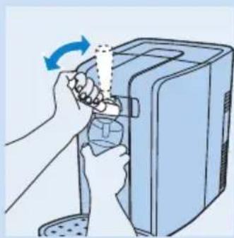
3 Open the tap in one quick, smooth movement.
The beer only flows properly into the glass if the tap is completely open. If the tap is only half open, the beer is forced through the tap, causing it to foam more strongly.
Let the beer to flow down the inside of the glass.
4 To vary the size of the beer head, vary the angle at which you hold the glass under the spout and vary the distance between the glass and the spout.
The more upright and the closer to the spout you hold the glass, the more foam you obtain.
Note: Do not let the end of the spout touch the beer glass, the beer or the beer head. Any beer residues present on the spout affect the forming of the beer head.
5 Slowly move the glass to vertical position while you pour your beer.
6 Fill the glass until the foam almost flows over the rim of the glass.
7 Close the tap in one smooth movement.
Note: The pump may go on.
natural_image
Illustration of hands operating a computer tower with a scroll wheel (no text or symbols)
natural_image
Diagram showing a hand turning a bottle with a blue arrow indicating rotation (no text or symbols)8 Europe (except Germany and the UK): For the best end result, remove excess foam from the glass by moving a skimmer over the rim of the glass at an angle of 45^ in one smooth movement.
Note: Never leave the skimmer lying on the worktop, but put it in a clean glass with fresh, cold water or rinse it right away. Only pass the skimmer over the glass once, as further skimming has a negative effect on the quality of the beer head.
▶You now have a perfect draft beer.
Serving a freshly poured beer
1 Dry the bottom of the glass by passing it over a cloth.
2 Use a clean beer mat for your guest.
3 Pick up the glass in the middle and serve the beer on the beer mat. Make sure the beer brand logo (if present on the glass) faces your guest.
3 different beer pouring traditions
| Step European (except Germany and UK) | German British | |
| 1 Rinse a glass and let it drain. Rinse a glass and let it drain. Rinse a glass and let it drain. | ||
| 2 Hold the glass next to the opening of the spout. | Hold the glass under the opening of the spout at an angle of approx. 45°C. | Hold the glass under the opening of the spout at an angle of approx. 45°C. |
| 3 Open the tap fully in one smooth movement. | Open the tap fully in one smooth movement. | Open the tap fully in one smooth movement. |
| 4 Move the glass under the spout at an angle of approx. 45°C and let the beer flow down the inside of the glass. | Let the beer flow down the inside of the glass. | Let the beer flow down the inside of the glass. |
| 5 Do not let the spout touch theglass, the beer or the foam. | Do not let the spout touch the glass, the beer or the foam. | Do not let the spout touch the glass, the beer or the foam. |
| 6 The angle at which you hold the glass while you pour beer determines the ultimate size of the foam head. The more upright you hold the glass, the higher the foam head becomes. | The angle at which you hold the glass while you pour beer determines the ultimate size of the foam head. The more upright you hold the glass, the higher the foam head becomes. | The angle at which you hold the glass while you pour beer determines the ultimate size of the foam head. The more upright you hold the glass, the higher the foam head becomes. |
| 7 Fill the glass until the beer almost flows over the rim of the glass. | a. Let beer flow into the glass until it contains two-thirds beer and one-third foam. | Fill the glass until the beer almost flows over the rim of the glass. |
| b. Close the tap and put the glass down for 1 minute to allow the foam to settle. | ||
| c. Repeat steps 2 to 6 and fill the glass up to the rim. | ||
| 8 Close the tap in one smooth movement. | Close the tap in one smooth movement. | Close the tap in one smooth movement. |
| 9 a. Move the glass away from the spout to prevent drops of beer from falling onto the foam head. | Move the glass away from the spout to prevent drops of beer from falling onto the foam head. | Move the glass away from the spout to prevent drops of beer from falling onto the foam head. |
| b. Remove the foam that rises beyond the rim of the glass by passing a skimmer over the rim of the glass at an angle of 45°. | ||
| 10 Your beer is now ready to be served. | Your beer is now ready to be served. | Your beer is now ready to beserved. |
Replacing the keg

natural_image
Diagram of a hand operating a mechanical device with a blue arrow indicating direction (no text or symbols present)The keg is empty when only foam comes out of the spout and no beer. HD3620 only: the display also indicates that the keg is empty.
1 Press the release button to the right to open the doors. Make sure you open the doors fully.
natural_image
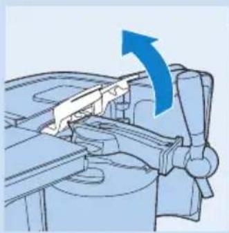
Mechanical assembly diagram showing a lever mechanism with an upward arrow (no text or symbols)2 Lift the blue locking levers completely.

natural_image
Mechanical assembly diagram showing a cylindrical component being inserted into a housing (no text or symbols visible)
3 Tilt the keg with the assembled tap unit towards you and take it out of the appliance.
4 Press on the release buttons on both sides of the tap unit (1). The tap unit is released from the keg with a click and you can remove it (2).
You have to remove the tap unit from the keg before you can replace the tube.
Always replace the tube when you install a new keg. Never use a tube for more than 30 days.
5 See chapter 'Preparing for use' for instructions on how to place the tap unit on the keg and how to place the keg into the appliance.
Cleaning
Clean the appliance when you replace the keg or when you store the appliance for a longer period.
Never use scouring pads, scouring agents or aggressive liquids such as petrol or acetone to clean the appliance.
natural_image
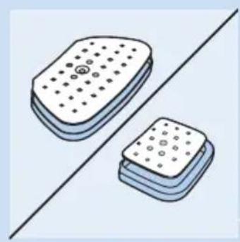
Illustration of two stacked electronic components with dot patterns, separated by a diagonal line (no text or symbols)1 Always unplug the appliance before you clean it.
2 Clean the outside of the appliance with a damp cloth.
3 Always clean the tap unit as described in chapter 'Replacing the keg' to avoid sticky beer residues.
4 Remove and disassemble the drip tray and the drip tray cover.

natural_image
Diagram of a robotic arm with a blue arrow indicating upward motion (no text or symbols)5 You can remove the tap handle by pulling it out of the tap body.
6 Clean the tap unit, the drip tray and the drip tray cover with hot water and, if necessary, some washing-up liquid.
Hot water may cause burns. Always check if the water is not too hot before you clean these parts under the tap.
Only the drip tray, the drip tray cover and the spout are dishwasher-proof.
Environment
natural_image
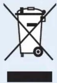
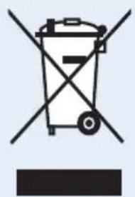
Symbol of a trash bin with crossed lines indicating no waste or restriction, and a solid black rectangle below (no text or symbols)- Do not throw away the appliance with the normal household waste at the end of its life, but hand it in at an official collection point for recycling. By doing this, you help to preserve the environment.
Removing the cooling element
The cooling element inside the appliance contains a substance that may pollute the environment. Therefore you must remove the cooling element before you discard the appliance.
You can also take or send the appliance to a Philips service centre. The staff of this centre will remove the cooling element for you and will dispose of it in an environmentally safe way.
Only remove the cooling element when you discard the appliance.
Be careful of the paste on the cooling element and adjacent parts. If this paste ends up on your clothes, it causes a permanent stain.
Remove the cooling element in the following way:

natural_image
Illustration of a hand operating a mechanical device with a blue circular arrow indicating rotation (no text or symbols present)1 Unplug the appliance.
2 Slide the release button to the right to open the doors.
There are two holes near the hinges of the doors on either side.
3 Remove the four screws located in these holes with a screwdriver.
4 Remove the back cover from the appliance.

natural_image
Illustration of a hand opening a device into a container with an arrow indicating direction (no text or symbols)
natural_image
Illustration of hands using a tool to adjust or install electronic components, with a blue arrow indicating direction (no text or symbols present)5 Pull the cooling fan out of the appliance.
Now you see an aluminium plate with fins on it and with two screw holes.

natural_image
Illustration of a hand using a tool to adjust or install a heat exchanger component (no text or symbols visible)
natural_image
Diagram of a mechanical device with a blue arrow pointing to a component, no visible text or symbols6 Undo the screws with a screwdriver.
7 Remove the aluminium plate.
After you have removed the aluminium plate, you see a white plate of approx. 4 x 4cm. This is the actual cooling element.
8 Place the shaft of a screwdriver against one side of the cooling element and push the cooling element off the back of the aluminium plate.
9 Cut the wires attached to the cooling element.
Do not connect the appliance to the mains again after you have removed the cooling element.
Never reassemble the cooling element once you have removed it.
10 Hand in the cooling element at an official collection point for chemical waste.
Guarantee & service
If you need information or if you have a problem, contact us online at www.philips.com or call the PerfectDraft call centre. Their phone number is 078-250159 (Belgium), 01801-324000 (Germany) or 0900-2224222 (Netherlands).
When you take the appliance to your dealer or a Philips service centre for determination of the cause of the problem, also bring the tube and the keg.
Guarantee restrictions
Your guarantee becomes invalid if:
- you do not use the appliance according to the instructions in this user manual.
- you use damaged kegs in this appliance.
- you do not install the kegs according to the instructions in this user manual.
- you use kegs from other suppliers than the ones mentioned in this user manual.
The kegs and tubes are not covered by this guarantee.
Troubleshooting
If you are unable to solve the problem with the information below, contact us online at www.philips.com or call the PerfectDraft call centre at 078-250159 (Belgium), 01801-324000 (Germany) or 0900-2224222 (Netherlands).
Problem Solution
Appliance general
| It is not possible to close the doors. | Make sure you push down the blue locking levers until they are in horizontal position before you close the doors. |
| Make sure the tube is placed correctly in the tap unit and the tap handle is in upright position. See chapter 'Preparing for use', section 'Placing the tube into the tap unit'. | |
| Make sure the tap unit is placed correctly on the keg. | |
| There is frost on the keg or on the appliance. | Unplug the appliance and let the keg or appliance defrost. Dry the appliance or keg with a cloth. |
| Make sure that the doors are properly closed. For instructions on how to close the doors, see the chapter 'Preparing for use', section 'Placing the keg into the appliance'. It is normal for some frost to be present on the back of the keg. | |
| Beer leaks out of the appliance. | Make sure that the tap unit and the tube are placed correctly (see chapter 'Preparing for use', sections 'Placing the tap unit onto the keg' and 'Placing the tube into the tap unit'). |
| Remove the tap unit and tube and reinstall them. If the problem continues to occur, contact the PerfectDraft call centre in your country to obtain a new tube. | |
| The appliance makes a sound. | Because the appliance chills constantly, the fan works continuously. |
| The pump may go on while you pour beer to maintain the right pressure. When you are not pouring beer, the pump also goes on every now and then to keep the appliance at the right pressure. | |
| If the appliance makes a hissing sound, the tap unit may not be properly connected to the keg. Make sure you rinse the tap unit thoroughly. It is essential that all rubber parts of the tap unit are moist before you assemble the tap unit onto the keg. | |
| The pump goes on frequently when I am not pouring beer. | Reinstall the tap unit and the keg by following the instructions in sections 'Placing the tap unit onto the keg' and 'Placing the keg into the appliance' in chapter 'Preparing for use'. If this does not help, try another keg together with a new tube. If the problem continues to occur, contact the PerfectDraft call centre in your country. |
Tap unit
| It is difficult to place the tap unit onto the keg. | Make sure no old beer is left in the tap unit. Clean the entire tap unit with hot water and, if necessary, some washing-up liquid. |
| It is difficult to press the release buttons to remove the tap unit. | First remove the keg from of the appliance. Then press the release buttons to remove the tap unit from the keg. |
| Beer residues may cause the tap unit to stick to the keg. Clean the tap unit with hot water and, if necessary, some washing-up liquid to dissolve beer residues. Then remove the tap unit from the keg. |
Problem Solution
| It is not possible to place the keg with the assembled tap unit in the appliance. | Make sure the tap unit is placed correctly on the keg. Push the tap unit down firmly when you place it onto the keg. See chapter 'Preparing for use', section 'Placing the tap unit onto the keg'. |
| Check if you have lifted the blue locking levers properly and push them down after you have installed the keg. | |
| The tube cannot be removed from the tap unit. | Remove the tap unit first before you remove the tube. Rinse the tap unit with hot water. Press the tube release button and pull the tube out of the spout. |
| It is difficult to place the tube into the tap unit. | Make sure the tube is placed correctly (see chapter 'Preparing for use', section 'Placing the tube into the tap unit'). |
| Make sure you clean the tap unit with hot water before you insert a new tube. | |
| The tube may be broken. Contact the PerfectDraft call centre in your country to obtain a new tube. | |
| LCD display/LED indicator lights | |
| The red indicator light flashes (HD3610). | Remove the tap unit, clean it and reinstall the tap unit. If this does not help, try another keg with a new tube. |
| If the problem continues to occur, please contact the PerfectDraft call centre in your country. | |
| There is a green dash on the display and the appliance does not work (HD3620). | Make sure that the tap unit is placed correctly (see chapter 'Preparing for use', section 'Placing the tap unit onto the keg'). |
| There is a green or red dash on the display and the background light flashes (HD3620). | Remove the tap unit, clean it and reinstall the tap unit. If this does not help try another keg with a new tube. |
| If the problem continues to occur, please contact the PerfectDraft call centre in your country. | |
| The display shows the wrong volume (HD3620). | For proper functioning of the volume indication, it is crucial that you open the tap handle completely (see chapter 'How to pour a perfect beer'). |
| In case of a power failure or if the appliance has been disconnected from the mains, the level indication will be accurate again after you have poured a few glasses of beer. | |
| Pouring beer | |
| No beer comes out when I pull the tap handle. | Perhaps the keg is empty. Put a new keg into the appliance. |
| Make sure the tube is fitted correctly in the tap unit (see chapter 'Preparing for use', section 'Placing the tube into the tap unit'). | |
Problem Solution
| Make sure that the tap unit is placed correctly on the keg (see chapter 'Preparing for use', section 'Placing the tap unit onto the keg'). | |
| Too much foam comes out of the appliance. | Make sure you open the tap completely when you pour beer (see chapter 'How to pour a perfect beer'). |
| The beer is too warm. Wait until the beer is cold enough to be poured, i.e. when temperature on the display is green (HD3620 only) or when the green indicator light goes on (HD3610). | |
| The keg has been shaken too much. Wait half an hour for the beer to settle. | |
| The first glass can contain more foam than usual. Try pouring a second glass. | |
| The tube may not function properly. Contact the PerfectDraft call centre in your country to obtain a new tube. | |
| The foam head is too high. See chapter 'How to pour a perfect beer'. | |
| The beer that comes out of the appliance is flat. | Check if the keg has been open for over 30 days and check if the expiry date of the keg has passed. |
| Perhaps the glasses you used were not clean enough. Rinse the glasses with water and some washing-up liquid. Rinse them thoroughly with cold water to remove all grease and soap residues | |
| Pour beer as described on the keg and in this user manual (see chapter 'How to pour a perfect beer'). | |
| The foam head collapses very quickly. | Perhaps the glasses you used were not clean enough. Rinse the glasses with water and some washing-up liquid. Rinse them thoroughly with cold water to remove all grease and soap residues. |
| Make sure the beer is cold enough to be poured, i.e. when temperature on the display is green (HD3620) or when the green indicator light goes on (HD3610). | |
| The keg fell, can I still use it? | When it is an unopened keg and it does not have any visual damage, you can try to use it. When the keg is already open, you cannot use the keg anymore and have to install a new keg. |
| The beer tastes bad. Make sure you keep the appliance plugged in all the time. Once the keg has been opened and is kept cool, the beer stays fresh for 30 days. Check the expiry date on the keg before you install a new keg. | |
| Always clean the tap unit and place a new tube into it when you install a new keg. | |
| Make sure you use clean glasses. | |
| Cooling | |
| The temperature on the display goes up (HD3620). | Make sure that the doors are properly closed (see chapter 'Preparing for use', section 'Placing the keg into the appliance'). |
| During hot days, put the appliance in a cooler place. | |
Problem Solution
| Place the appliance in an environment with an ambient temperature between 3°C and 32°C. Leave at least 10cm free space around the appliance. Do not expose the appliance to direct sunlight. | |
| Check if the fan outlet at the back of the appliance is free from dust and/or other particles. | |
| The appliance does not chill the beer sufficiently | At an ambient temperature of 23°C, chilling the keg takes approximately 12-15 hours. |
| At higher ambient temperatures, chilling the keg takes longer. When you use the appliance above 32°C (HD3620) or 30°C (HD3610), the beer temperature may rise above 3°C. When the temperature decreases to below 32°C, the beer temperature drops to 3°C again. | |
| You can prechill the keg in upright position in the fridge for a while before you install the keg. |
Keg suppliers
If you need information about the keg or if you have a problem with your keg, you can contact the supplier of the keg in your country. You will find the phone numbers in the table below.
Country Brand Phone number Web address
| The Netherlands Dommelsch 0800-0230367 www.dommelsch.nl | |||
| Hertog Jan 0800-0230375 www.hertogjan.nl | |||
| Jupiter 0800-0230945 www.jupiler.nl | |||
| Grolsch 0800-1591 www.grolsch.nl | |||
| Bavaria | 0900-2282742 (Eur 0,10 p/m) | www.bavaria.nl | |
| Belgium | Stella Artois | 070-222918 | www.stella-artois.be |
| Jupiter 070-222912 | www.jupiler.be | ||
| Leffe | 078 250 159 | www.perfectdraft.com | |
| Luxembourg | Diekirch | 0035-2802131999 | - |
| Jupiter 0032 70-222912 | www.jupiler.be | ||
| Leffe | 0032 78 250 159 | www.perfectdraft.com | |
| Germany | Beck's Pils | 0180/1324000 (Eur 0,12 p/m) | www.perfectdraft.com |
| Beck's Gold | 0180/1324000 (Eur 0,12 p/m) | www.perfectdraft.com | |
| Diebels Alt 0180/1324000 (Eur 0,12 p/m) | www.perfectdraft.com | ||
| Diebels Pils | 0180/1324000 (Eur 0,12 p/m) | www.perfectdraft.com | |
| Hasseröder | 0180/1324000 (Eur 0,12 p/m) | www.perfectdraft.com | |
Einführung
natural_image
Diagram of a heat exchanger with airflow direction indicated by arrows (no text or symbols)natural_image
Illustration of a remote control with a blue arrow pointing to the button (no text or symbols)natural_image
Illustration of a door handle next to a grid-patterned device with a blue arrow pointing to it (no text or symbols)natural_image
Diagram of a hand valve with a blue arrow indicating downward motion (no text or symbols present)natural_image
Illustration of a hand pressing a small mechanical component with a blue arrow indicating downward motion (no text or symbols)natural_image
Diagram of two mechanical components with directional arrows indicating motion, no text or symbols presentnatural_image
Illustration of a hand using a faucet to lift a showerhead in a tiled room (no text or symbols)natural_image
Diagram showing a hand operating a mechanical component with directional arrows indicating motion (no text or symbols present)natural_image
Illustration of a mechanical clamp or tool with a blue arrow indicating force direction (no text or symbols)natural_image
Illustration of a hand pump mechanism with blue arrow indicating direction (no text or symbols)natural_image
Illustration of a hand inserting a device into a device with a blue arrow indicating direction (no text or symbols)natural_image
Diagram of a mechanical device with a blue arrow indicating direction, showing internal components and assembly (no text or symbols)natural_image
3D mechanical assembly diagram showing piston and cylinder components (no text or labels)natural_image
Mechanical assembly diagram showing a rotating component with blue arrow indicating rotation (no text or symbols)natural_image
Illustration of a device with a handle and blue directional arrows indicating movement or flow (no text or symbols)natural_image
Diagram of a device with three battery icons and a light bulb, no text or symbols presentDie Kühlung
natural_image
Simple diagram of three vertical oval shapes with battery icons below, no text or symbols presentnatural_image
Illustration of hands operating a computer with a scroll wheel (no text or symbols)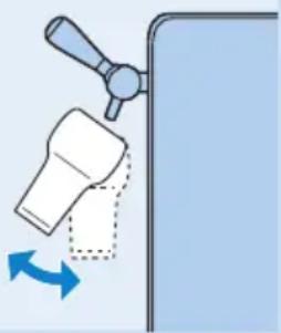
natural_image
Diagram showing a hand valve interacting with a bottle, with directional arrows indicating movement (no text or symbols)natural_image
Diagram of a hand operating a mechanical lever with a blue arrow indicating direction (no text or symbols present)
natural_image
Mechanical assembly diagram showing a blue arrow indicating direction (no text or symbols present)
natural_image
Mechanical assembly diagram showing a hand operating a cylindrical component with a blue arrow indicating direction (no text or symbols present)natural_image
Illustration of two electronic components with perforated bases, placed on a diagonal line (no text or symbols)natural_image
Diagram of a robotic arm with a blue arrow indicating upward motion (no text or symbols)natural_image
Symbol of a trash bin crossed with no text or numbers, representing waste sorting or disposal (no text present)natural_image
Diagram of a mechanical device with a hand operating a component, showing a blue circular motion indicator (no text or symbols)natural_image
Illustration of a hand inserting a device into a container with an arrow indicating direction (no text or symbols)
natural_image
Illustration of hands using a tool to adjust or install electronic components (no text or symbols visible)natural_image
Illustration of a hand holding a computer chassis with a blue circular arrow indicating rotation (no text or symbols present)natural_image
Diagram of a device with cable and a blue arrow indicating direction (no text or symbols)natural_image
Diagram of a mechanical lever with a blue upward arrow indicating force or movement (no text or symbols present)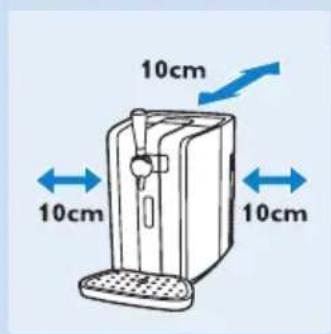

Le fût
Avertissement
natural_image
Diagram of a heat exchanger with airflow direction indicated by blue arrows (no text or symbols)natural_image
Illustration of a remote control with a blue arrow pointing to the button (no text or symbols)natural_image
Illustration of a device with a blue arrow pointing to a grid-like component (no text or symbols)natural_image
Diagram of a hand valve with a blue arrow indicating downward motion (no text or symbols present)natural_image
Illustration of a mechanical lever with a blue downward arrow indicating force or motion (no text or symbols)Avant utilisation
natural_image
Diagram of two mechanical components with directional arrows indicating rotation or movement (no text or symbols)natural_image
Illustration of a hand using a faucet to lift a showerhead in a tiled room (no text or symbols)natural_image
Illustration of a hand adjusting a mechanical component with directional arrows (no text or symbols)natural_image
Illustration of a hand turning a tool into a container with a blue arrow indicating force (no text or symbols)natural_image
Illustration of a mechanical lever mechanism with a blue arrow indicating direction (no text or symbols present)natural_image
Illustration of a hand inserting a device into a device with a blue arrow indicating direction (no text or symbols)natural_image
Diagram of a mechanical device with a blue arrow indicating direction, showing internal components and assembly (no text or symbols)natural_image
Mechanical assembly diagram showing a piston and cylinder inside a housing (no text or symbols)natural_image
Mechanical assembly diagram showing a rotating component with a blue arrow indicating rotation direction (no text or symbols present)natural_image
Illustration of a mechanical device with blue directional arrows indicating motion or flow (no text or symbols)natural_image
Simple diagram of three battery icons with a light bulb, no text or symbols presentnatural_image
Simple diagram of a three-panel air conditioner unit with indicator lights (no text or symbols)natural_image
Illustration of hands operating a computer tower with a scroll wheel (no text or symbols)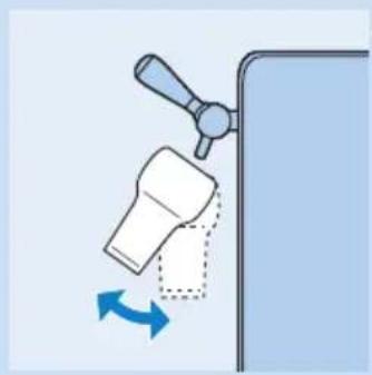
natural_image
Diagram showing a hand valve interacting with a bottle, with blue arrows indicating rotation (no text or symbols)natural_image
Diagram of a hand operating a mechanical lever with a blue arrow indicating direction (no text or symbols present)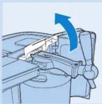
natural_image
Mechanical assembly diagram showing a lever mechanism with an upward arrow (no text or symbols)
natural_image
Mechanical assembly diagram showing a piston and valve mechanism (no text or labels)Remplacement du fût
natural_image
Illustration of two stacked electronic components with perforated bases, placed on a diagonal line (no text or symbols)natural_image
Diagram of a robotic arm with a blue arrow indicating upward motion (no text or symbols)Environnement
natural_image
Illustration of a hand operating a mechanical device with a blue circular arrow indicating rotation (no text or symbols present)
natural_image
Illustration of a hand inserting a device into a container with an arrow indicating direction (no text or symbols)
natural_image
Illustration of hands using a tool to adjust or install a mechanical component, with a blue arrow indicating direction (no text or symbols present)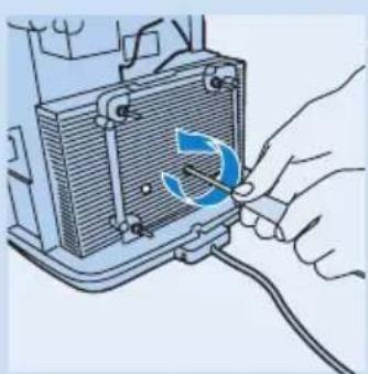
natural_image
Illustration of a hand using a tool to adjust or install a component, with no visible text or symbols.natural_image
Diagram of a device with cable and a blue arrow indicating direction (no text or symbols)natural_image
Diagram of a robotic arm with a blue arrow indicating upward motion (no text or symbols)
Attenzione
Avvertenza
natural_image
Diagram of a heat exchanger with airflow direction indicated by blue arrows (no text or symbols)natural_image
Diagram of two mechanical components with directional arrows indicating rotation or movement (no text or symbols)natural_image
Illustration of a hand operating a showerhead in a tiled room (no text or symbols)natural_image
Illustration of a hand adjusting a mechanical component with directional arrows (no text or symbols)natural_image
Illustration of a hand using a tool to lift a mechanical component, with a blue arrow indicating force direction (no text or symbols)natural_image
Illustration of a hand pump mechanism with a blue arrow indicating direction (no text or symbols)natural_image
Illustration of a device being inserted into a slot, with a hand pointing to the handle (no text or symbols present)natural_image
Diagram of a mechanical device with a blue arrow indicating direction, showing internal components and a handle (no text or symbols)natural_image
Technical illustration of a mechanical device with internal components and a blue arrow indicating motion (no text or symbols)natural_image
Mechanical assembly diagram showing a piston and crank mechanism with a blue arrow indicating motion (no text or symbols)natural_image
Illustration of a mechanical device with blue directional arrows indicating motion or flow (no text or symbols)natural_image
Diagram of a battery with three battery icons and a light bulb, no text or symbols presentnatural_image
Simple diagram of a three-panel air conditioner unit with indicator lights (no text or symbols)natural_image
Illustration of hands operating a computer tower with a scroll wheel (no text or symbols)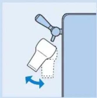
natural_image
Diagram showing a hand turning a bottle with a blue arrow indicating rotation (no text or symbols)natural_image
Diagram of a hand operating a mechanical lever with a blue arrow indicating direction (no text or symbols present)natural_image
Mechanical assembly diagram showing a lever mechanism with an upward arrow (no text or symbols)natural_image
Mechanical assembly diagram showing a cylindrical component being inserted into a housing (no text or symbols visible)natural_image
Illustration of two stacked electronic components with perforated bases, placed on a diagonal line (no text or symbols)natural_image
Symbol of a trash bin crossed with no text or numbers, representing waste sorting or disposal (no text present)natural_image
Illustration of a hand operating a mechanical device with a blue circular arrow indicating rotation (no text or symbols present)natural_image
Illustration of a hand opening a device into a container with an arrow indicating direction (no text or symbols)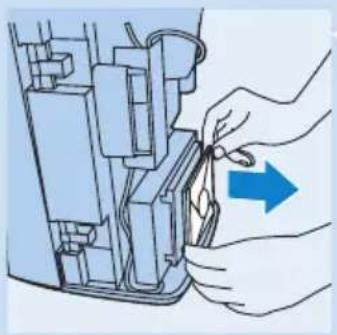
natural_image
Illustration of hands using a tool to adjust or install a mechanical component, with a blue arrow indicating direction (no text or symbols present)natural_image
Illustration of a hand using a tool to adjust or install a component with a blue circular arrow indicating rotation (no text or symbols present)natural_image
Diagram of a mechanical device with a blue arrow indicating direction, showing internal components and wiring (no text or symbols)Display LCD/spie a LED
natural_image
Diagram of a mechanical lever with a blue upward arrow indicating motion (no text or symbols)

Let op
natural_image
Diagram of a heat exchanger with airflow direction indicated by blue arrows (no text or symbols)natural_image
Illustration of a remote control with a blue arrow pointing to the button (no text or symbols)natural_image
Illustration of a door panel with a blue arrow pointing to it, next to a vertical structure (no text or symbols)natural_image
Illustration of a robotic arm with a blue arrow pointing to a handle (no text or symbols)natural_image
Illustration of a mechanical lever with a blue downward arrow indicating force or motion (no text or symbols)natural_image
Diagram of two mechanical components with directional arrows indicating rotation or movement (no text or symbols)natural_image
Illustration of a hand using a tool to lift a showerhead into a tiled wall (no text or symbols)natural_image
Illustration of a hand adjusting a mechanical component with directional arrows (no text or symbols)natural_image
Illustration of a hand using a tool to lift a mechanical component, with a blue arrow indicating downward motion (no text or symbols)natural_image
Illustration of a hand pump mechanism with a blue arrow indicating direction (no text or symbols)natural_image
Illustration of a hand inserting a device into a box with a blue arrow indicating direction (no text or symbols)natural_image
Diagram of a mechanical assembly with a blue arrow indicating direction (no text or symbols present)natural_image
3D mechanical assembly diagram showing internal components and a blue arrow indicating direction (no text or symbols)natural_image
Mechanical assembly diagram showing a rotating component with blue arrow indicating rotation (no text or symbols)4 Duw de blauwe vergrendelarmen omlaag tot ze in horizontale stand staan.
natural_image
Illustration of a device with blue directional arrows indicating flow or movement (no text or symbols)5 Sluit de deuren.
natural_image
Simple diagram of a three vertically oriented panel with battery icons and checkmark indicators (no text or labels)natural_image
Illustration of a hand inserting a device into a computer case with a blue arrow indicating rotation (no text or symbols)
natural_image
Diagram showing a hand valve interacting with a bottle, with a blue arrow indicating rotation (no text or symbols present)natural_image
Diagram of a hand operating a mechanical device with a blue arrow indicating direction (no text or symbols present)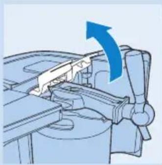
natural_image
Mechanical assembly diagram showing a lever mechanism with an upward arrow (no text or symbols)natural_image
Mechanical assembly diagram showing a cylindrical component being inserted into a housing (no text or symbols visible)natural_image
Illustration of two stacked electronic components with perforated bases, separated by a diagonal line (no text or symbols)natural_image
Diagram of a robotic arm with a blue arrow indicating upward motion (no text or symbols present)natural_image
Symbol of a trash bin crossed with no text or numbers, representing waste sorting or disposal (no text present)natural_image
Illustration of a hand operating a mechanical device with a blue circular arrow indicating rotation (no text or symbols present)natural_image
Illustration of a hand opening a device into a container with an arrow indicating direction (no text or symbols)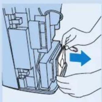
natural_image
Illustration of a hand using a tool to adjust or install a mechanical component, with no visible text or symbols.natural_image
Illustration of a hand using a tool to adjust or install a heat exchanger component (no text or symbols visible)
natural_image
Diagram of a device with a blue arrow pointing to a component, no visible text or symbols

- General description (Fig. 1)
- Tube unit (supplied with keg)
- Tap unit
- Keg
- Important
- The appliance
- Warning
- Caution
- The keg
- Electromagnetic fields (EMF)
- Before first use
- Installing the appliance
- Preparing for use
- Placing the tap unit onto the keg
- Placing the tube into the tap unit
- Placing the keg into the appliance
- Cooling
- LCD display (HD3620 only)
- Temperature indication
- Level indication
- Freshness indication
- Adapting the freshness indication
- Always write down the date and the number of days that the beer inside the keg is still fresh on the keg (see number of days on the display).
- Other indications
- LED indicator lights (HD3610 only)
- Cleaning beer glasses
- Pouring beer
- Serving a freshly poured beer
- Replacing the keg
- Cleaning
- Environment
- Removing the cooling element
- Guarantee & service
- Guarantee restrictions
- Troubleshooting
- Problem Solution
- Keg suppliers
- Einführung
- Die Kühlung
- Le fût
- Avertissement
- Avant utilisation
- Remplacement du fût
- Environnement
- Attenzione
- Avvertenza
- Let op
Brand : PHILIPS
Model : PerfectDraft HD3610
Category : Beer dispenser