
XTi 6002 - Receiver CROWN - Free user manual and instructions
Find the device manual for free XTi 6002 CROWN in PDF.


| Product Type | Professional Power Amplifier |
| Brand | Crown |
| Model | XTi 6002 |
| Number of Channels | 2 |
| Output Power (Stereo 4 Ω) | 1200 W per channel |
| Output Power (Bridge 8 Ω) | 2400 W |
| Frequency Response | 20 Hz - 20 kHz (±0.5 dB) |
| Signal-to-Noise Ratio | > 100 dB (A-weighted) |
| Total Harmonic Distortion (THD) | < 0.05 % |
| Input Impedance | 20 kΩ (balanced), 10 kΩ (unbalanced) |
| Input Connectors | XLR and 6.35 mm jack (balanced) |
| Output Connectors | Screw terminals and Speakon |
| Protections | Thermal, short-circuit, DC, intelligent limiter |
| Cooling | Variable speed fan, front-to-back airflow |
| Power Supply | AC 100-240 V, 50/60 Hz |
| Power Consumption | Approximately 2000 W at full power |
| Dimensions (W × H × D) | 483 × 89 × 411 mm (19", 2U) |
| Weight | 15.2 kg |
| Chassis Material | Robust steel |
| Operating Temperature | 0 °C to 40 °C |
| Maintenance and Cleaning | Unplug before cleaning; use a dry, lint-free cloth |
| Safety | Do not expose to water, do not obstruct ventilation grilles |
| Spare Parts and Repairability | Contact Crown authorized after-sales service |
Frequently Asked Questions - XTi 6002 CROWN
User questions about XTi 6002 CROWN
0 question about this device. Answer the ones you know or ask your own.
Ask a new question about this device
Download the instructions for your Receiver in PDF format for free! Find your manual XTi 6002 - CROWN and take your electronic device back in hand. On this page are published all the documents necessary for the use of your device. XTi 6002 by CROWN.
USER MANUAL XTi 6002 CROWN
XTi2 Series Operation Manual

natural_image
Front view of a multi-tiered rack-mounted server rack with multiple 1002 and 6002 XTR80023D units, each labeled 'crown' (no additional text or symbols visible)XTi 1002
XTi 2002
XTi 4002
XTi 6002
Obtaining Other Language Versions: To obtain information in another language about the use of this product, please contact your local Crown Distributor. If you need assistance locating your local distributor, please contact Crown at 574-294-8000.
This manual does not include all of the details of design, production, or variations of the equipment. Nor does it cover every possible situation which may arise during installation, operation or maintenance.
The information provided in this manual was deemed accurate as of the publication date. However, updates to this information may have occurred. To obtain the latest version of this manual, please visit the Crown website at www.crownaudio.com.
Trademark Notice: Crown, Crown Audio, and Amcron are registered trademarks of Crown International. Other trademarks are the property of their respective owners. Later versions of this manual and additional information about this product may be available at the Crown website at www.crownaudio.com.
Some models may be exported under the name Amcron®
©2011 by Harman International, 1718 W. Mishawaka Rd., Elkhart, Indiana 46517-9439 U.S.A. Telephone: 574-294-8000.
Important Safety Instructions
- Read these instructions.
- Keep these instructions.
- Heed all warnings.
- Follow all instructions.
-
Do not use this apparatus near water.
-
Clean only with a dry cloth.
-
Do not block any ventilation openings. Install in accordance with the manufacturer's instructions.
-
Do not install near any heat sources such as radiators, heat registers, stoves, or other apparatus (including amplifiers) that produce heat.
-
Do not defeat the safety purpose of the polarized or grounding-type plug. A polarized plug has two blades with one wider than the other. A grounding-type plug has two blades and a third grounding prong. The wide blade or the third prong is provided for your safety. If the provided plug does not fit into your outlet, consult an electrician for replacement of the obsolete outlet.
-
Protect the power cord from being walked on or pinched, particularly at plugs, convenience receptacles, and the point where they exit from the apparatus.
-
Only use attachments/accessories specified by the manufacturer.
-
Use only with a cart, stand, tripod, bracket, or table specified by the manufacturer, or sold with the apparatus. When a cart is used, use caution when moving the cart/apparatus combination to avoid injury from tip-over.
-
Unplug this apparatus during lightning storms or when unused for long periods of time.
-
Refer all servicing to qualified service personnel. Servicing is required when the apparatus has been damaged in any way, such as power-supply cord or plug is damaged, liquid has been spilled or objects have fallen into the apparatus, the apparatus has been exposed to rain or moisture, does not operate normally, or has been dropped.
-
Use the mains plug to disconnect the apparatus from the mains.
-
WARNING: TO REDUCE THE RISK OF FIRE OR ELECTRIC SHOCK, DO NOT EXPOSE THIS APPARATUS TO RAIN OR MOISTURE.
-
DO NOT EXPOSE THIS EQUIPMENT TO DRIPPING OR SPLASHING AND ENSURE THAT NO OBJECTS FILLED WITH LIQUIDS, SUCH AS VASES, ARE PLACED ON THE EQUIPMENT.
-
THE MAINS PLUG OF THE POWER SUPPLY CORD SHALL REMAIN READILY OPERABLE.


TO PREVENT ELECTRIC SHOCK DO NOT REMOVE TOP OR BOTTOM COVERS. NO USER SERVICEABLE PARTS INSIDE. REFER SERVICING TO QUALIFIED SERVICE PERSONNEL.
TO COMPLETELY DISCONNECT THIS EQUIPMENT FROM THE AC MAINS, DISCONNECT THE POWER SUPPLY CORD PLUG FROM THE AC RECEPTACLE. THE MAINS PLUG OF THE POWER SUPPLY CORD SHALL REMAIN READILY OPERABLE.
WATCH FOR THESE SYMBOLS:

The lightning bolt triangle is used to alert the user to the risk of electric shock.

The exclamation point triangle is used to alert the user to important operating or maintenance instructions.


IMPORTANT

XTi2 Series amplifiers require Class 2 output wiring.
MAGNETIC FIELD
CAUTION! Do not locate sensitive high-gain equipment such as preamplifiers or tape decks directly above or below the unit. Because this amplifier has a high power density, it has a strong magnetic field which can induce hum into unshielded devices that are located nearby. The field is strongest just above and below the unit.
If an equipment rack is used, we recommend locating the amplifier(s) in the bottom of the rack and the preamplifier or other sensitive equipment at the top.
FCC COMPLIANCE NOTICE
This device complies with part 15 of the FCC rules. Operation is subject to the following two conditions: (1) This device may not cause harmful interference, and (2) this device must accept any interference received, including interference that may cause undesired operation.
CAUTION: Changes or modifications not expressly approved by the party responsible for compliance could void the user's authority to operate the equipment.
NOTE: This equipment has been tested and found to comply with the limits for a Class B digital device, pursuant to part 15 of the FCC Rules. These limits are designed to provide reasonable protection against harmful interference in a residential installation. This equipment generates, uses, and can radiate radio frequency energy and, if not installed and used in accordance with the instruction manual, may cause harmful interference to radio communications. However, there is no guarantee that interference will not occur in a particular installation. If this equipment does cause harmful interference to radio or television reception, which can be determined by turning the equipment off and on, the user is encouraged to try to correct the interference by one or more of the following measures:
- Reorient or relocate the receiving antenna.
- Increase the separation between the equipment and receiver.
- Connect the equipment into an outlet on a circuit different from that to which the receiver is connected.
- Consult the dealer or an experienced radio/TV technician for help.
DECLARATION OF CONFORMITY
Issued By: Harman International.
1718 W. Mishawaka Rd.
Elkhart, IN 46517 U.S.A.
FOR FIELD SERVICE
QUESTIONS CALL: 1 800 342 6939
European Representative's Name and Address:
David J. Budge
10 Harvest Close
Yateley
GU46 6YS
United Kingdom
Equipment Type: Power amplifiers
Family Name: XTi2 Series
Model Names: XTi1002, XTi2002, XTi4002, XTi6002
EMC Standards:
EN 55103-1:1997 Electromagnetic Compatibility – Product Family Standard for Audio, Video, Audio-Visual and Entertainment Lighting Control Apparatus for Professional Use, Part 1: Emissions
EN 55103-1:1997 Magnetic Field Emissions-Annex A @ 10 cm and 1 M
EN 61000-3-2:2005 & Amd 1: 2008 Limits for Harmonic Current Emissions (equipment input current <16A per phase)
EN 61000-3-3:1998 Limitation of Voltage Fluctuations and Flicker in Low-Voltage Supply Systems Rated Current <16A
EN 55022:2006 Limits and Methods of Measurement of Radio Disturbance Characteristics of ITE: Radiated, Class B Limits; Conducted, Class B
EN 55103-2:1997 Electromagnetic Compatibility – Product Family Standard for Audio, Video, Audio-Visual and Entertainment Lighting Control Apparatus for Professional Use, Part 2: Immunity
EN 61000-4-2:2001 Electrostatic Discharge Immunity (Environment E2-Criteria B, 4k V Contact, 8k V Air Discharge)
EN 61000-4-3:2006 Radiated, Radio-Frequency, Electromagnetic Immunity (Environment E2, Criteria A)
EN 61000-4-4:2007 Electrical Fast Transient/Burst Immunity (Criteria B)
EN 61000-4-5:2006 Surge Immunity (Criteria B)
EN 61000-4-6:2006 Immunity to Conducted Disturbances Induced by Radio-Frequency Fields (Criteria A)
EN 61000-4-11:2001 Voltage Dips, Short Interruptions and Voltage Variation
Safety Standard:
IEC 60065: 2001: 7Ed & Amd 1: 2005 Safety Requirements - Audio Video and Similar Electronic Apparatus
I certify that the product identified above conforms to the requirements of the EMC Council Directive 89/336/EEC as amended by 92/31/EEC, and the Low Voltage Directive 73/23/EES as amended by 93/68/EEC.
Signed

Scott Potosky
Title: Director of Engineering Date of Issue: February 1, 2011
Get Started
Stereo DSP Off
This is the default mode the amplifier is set to from the factory. The amplifier is configured for stereo mode with all processing disabled.
- Connect Left/Right signal source to Channel 1 and Channel 2 using the XLR connectors.
- Connect a speaker to each channel output using Speakon®, Banana Plugs, or bare wire.

WARNING: Before you start to set up your amplifier, make sure you read and observe the Important Safety Instruc tions found at the beginning of this manual.

Factory Preset #2: BRIDGE
Putting the amplifier in BRIDGE (bridge-mono) mode delivers the power of both amp channels into a single 8 or 4 ohm load. The XTi2 Series amplifiers come pre-loaded with a preset that makes it easy to configure the amplifier for this operation.
Before you get started ensure that you:
- Connect signal source to Channel 1 and Channel 2 using XLR connectors (the amplifier inputs will automatically be summed together when selecting this preset).
- Connector the speaker as shown.
a. If using the binding post outputs, connect the positive terminal of the speaker to the positive terminal of Channel 1 and the negative terminal of the speaker to the positive terminal of Channel 2.
b. If using a Speakon® connector, connect the positive terminal of the speaker to 1+ and the negative terminal to 2+. Plug the connector into the Channel 1 output only.
Follow these quick steps to configure the amplifier for BRIDGE operation:
- Push the "Set/Enter" button and you will see the word "Preset" flashing.
- Push the "Set/Enter" button again to enter the list of presets in the amplifier.
- Push the "Next/Down" or "PREV/UP" button until the screen displays "Bridge".
- Push the "Set/Enter" button to confirm your selection.
- The display will now read "Bridge" with the Y icon and Bridge icon highlighted.
NOTE: Custom wiring should only be performed by qualified personnel.
Get Started
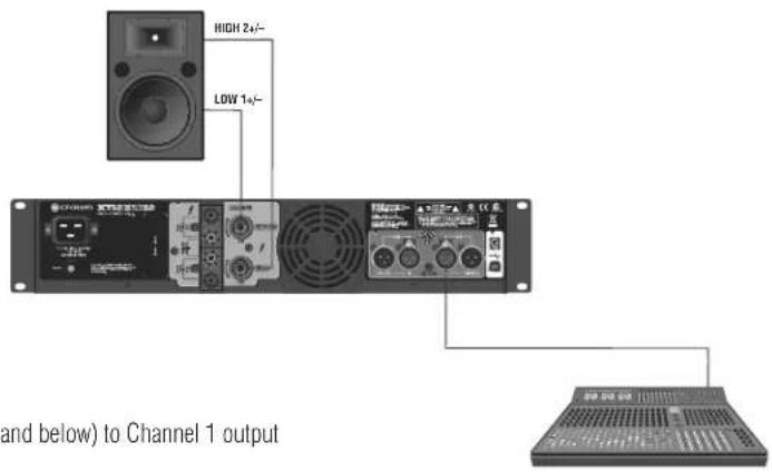
Factory Preset #3: XOVER
Putting the amplifier in XOVER mode enables a 1.2kHz 4th order (24dB/octave) filter that sends frequencies of 1.2kHz and below to Channel 1 output and frequencies of 1.2kHz and above to Channel 2 output. The XTi2 Series amplifiers come pre-loaded with a preset that makes it easy to configure the amplifier for this operation.
Before you get started ensure that you:
- Connect signal source to Channel 1 ONLY using an XLR connector (the amplifier inputs will automatically be put into Y mode when selecting this preset).
- Connector the speaker as shown.
a. Connect the speaker you wish to receive the low and mid frequencies (1.2kHz and below) to Channel 1 output using Speakon ^® , Banana Plugs, or bare wire.
b. Connect the speaker you wish to receive the high frequencies (1.2kHz and above) to Channel 2 output using Speakon ^® , Banana Plugs, or bare wire.
Follow these quick steps to configure the amplifier for XOVER operation:
- Push the "Set/Enter" button and you will see the word "Preset" flashing.
- Push the "Set/Enter" button again to enter the list of presets in the amplifier.
- Push the "Next/Down" or "PREV/UP" button until the screen displays "BIAMP".
- Push the "Set/Enter" button to confirm your selection.
- The display will now read "BIAMP" with the Y icon and XOV icon highlighted.
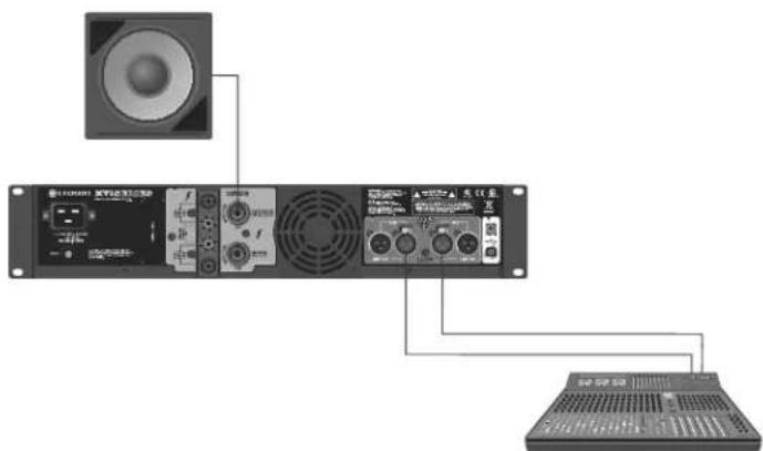
Factory Preset #4: BRG SUBS
Putting the amplifier in BRG SUBS (bridged subs) mode allows you to bridge the amplifier for use with a single 8 or 4 ohm subwoofer. The inputs are automatically summed, a 90Hz 4th order (24dB/octave) LowPass filter is enabled, and the output mode is put into bridge-mono mode. The XTi2 Series amplifiers come pre-loaded with a preset that makes it easy to configure the amplifier for this operation.
Before you get started ensure that you:
- Connect signal source to Channel 1 and Channel 2 using XLR connectors (the amplifier inputs will automatically be summed together when selecting this preset).
- Connector the speaker as shown.
a. If using the binding post outputs, connect the positive terminal of the speaker to the positive terminal of Channel 1 and the negative terminal of the speaker to the positive terminal of Channel 2.
b. If using a Speakon® connector, connect the positive terminal of the speaker to 1+ and the negative terminal to 2+. Plug the connector into the Channel 1 output only.
Follow these quick steps to configure the amplifier for XOVER operation:
- Push the "Set/Enter" button and you will see the word "Preset" flashing.
- Push the "Set/Enter" button again to enter the list of presets in the amplifier.
- Push the "Next/Down" or "PREV/UP" button until the screen displays "XOVER".
- Push the "Set/Enter" button to confirm your selection.
- The display will now read "XOVER" with the Y icon and XOV icon highlighted.
Get StartedGet Started
Factory Preset #5: SUBSYNTH
Putting the amplifier in SUBSYNTH mode allows you to turn on the SubHarmonic Synth feature for use with a subwoofer on both channels. The inputs are automatically summed, a 90Hz 4th order (24dB/octave) filter is enabled on both Channel 1 and Channel 2, and the SubHarmonic Synth feature is turned on at +12dB level. The XTi2 Series amplifiers come pre-loaded with a preset that makes it easy to configure the amplifier for this operation.
Before you get started ensure that you:
-
Connect signal source to Channel 1 and Channel 2 using XLR connectors (the amplifier inputs will automatically be summed together when selecting this preset).
-
Connector the speaker as shown.
a. Connect a speaker to each channel output using Speakon©, Banana Plugs, or bare wire
Follow these quick steps to configure the amplifier for SUBSYNTH operation:
-
Push the "Set/Enter" button and you will see the word "Preset" flashing.
-
Push the "Set/Enter" button again to enter the list of presets in the amplifier.
-
Push the "Next/Down" or "PREV/UP" button until the screen displays "SUBSYNTH".
-
Push the "Set/Enter" button to confirm your selection.
-
The display will now read "SUBSYNTH" with the Y icon and XOV icon highlighted.
Ensure Proper Cooling
When using an equipment rack, mount units directly on top of each other. Close any open spaces in rack with blank panels. DO NOT block front or rear air vents. The side walls of the rack should be a minimum of two inches (5.1 cm) away from the amplifier sides, and the back of the rack should be open.

CAUTION: Before you begin installing your amplifier, make sure it is disconnected from the power source, with the power switch in the "off" position and all level controls turned completely down (counterclock wise).

Welcome

There's no debate – when you choose Crown's XTi2 Series, you're choosing one of the most powerful and innovative amplifiers on the market today. That's because the all-new XTi2 Series amps continue to set the standard for unmatched performance and value, delivering the goods night after night without breaking a sweat.
With such innovations as a universal tracking switch-mode power supply and a fully integrated suite of speaker processing tools, these amps are at the top of their class when it comes to thermal efficiency and system flexibility.
You also have greatly improved control capabilities. The addition of Peakx Plus™ Limiters gives you full command over threshold, attack and release, and we enhanced the Subharmonic Synth so you can easily manage frequency, gain and filter type, allowing for application specific tuning.
Plus, you'll now be able to tailor fan speed for specific applications with the new Advanced Thermal controls and have software visibility of the Power Supply Temperature and AC Line Voltage with the new Advanced Monitoring controls. Combine all of that with integrated cast-aluminum rack handles for maximum durability and portability and you have the power to move you – and the world.
Next Generation Features include:
- PeakX Plus™ Limiters provide the ultimate in system performance and protection by allowing full control over threshold, attack, and release
- Enhanced Subharmonic Synth section provides user control over crossover frequency, max. harmonic frequency, and 1 PEQ filter for system-specific tuning
- New Advanced Thermal controls allow for 3 user-defined fan mode controls – normal, early and full speed – for matching fan performance to a specific application
• New Advanced Monitoring provides software visibility of the Power Supply Temperature and AC Line Voltage - Increased number of presets to a total of 50; 49 of which are user definable
- Integrated –cast aluminum handles for easy handling and enhanced durability
- Locking power cord clip provides a secure connection between the amplifier and power cord
- Updated HiQnet Band Manager™ and System Architect™ control software
How to Use This Manual
This manual provides you with the necessary information to safely and correctly setup and operate your amplifier. It does not cover every aspect of installation, setup, or operation that might occur under every condition. For additional information, please consult Crown's Amplifier Application Guide (available at www.crownaudio.com), Crown Technical Support, your system installer or retailer.
We strongly suggest you read all instructions, warnings and cautions contained in this manual. Also, for your protection, please send in your warranty registration card today. And save your bill of sale – it's your official proof of purchase.
Front Panel Features
Indicators:
Ready Indicator: Two green LEDs, one for each channel, illuminate when the amplifier is ready to produce audio.
Signal Presence Indicator: Two green LEDs, one for each channel, illuminate when the channel input exceeds -40dBu. Useful for troubleshooting cable runs.
-20 Indicator: Two green LEDs, one for each channel, illuminate when the output signal exceeds -20dB below clip.
-10 Indicator: Two green LEDs, one for each channel, illuminate when the output signal exceeds -10dB below clip.
Clip Indicator: Two red LEDs, one for each channel, illuminate at the threshold of audible distortion.
Thermal Indicator: Two red LEDs, one for each channel, illuminate when thermal compression begins due to excessive temperature conditions.


WARNING: Never connect the output to a power supply, battery or power main. Electrical shock may result.
Back Panel Features
XTi 1002, 2002, 4002
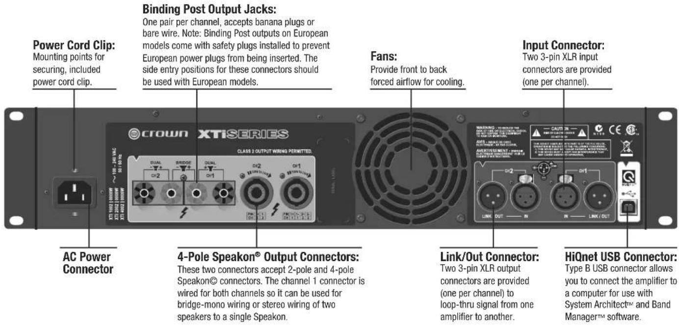
XTi 6002

Front Panel Navigation
From the front panel, you can change settings for several of the amplifier's integrated signal processing features: Input Y, Crossover Frequency, EQ, Delay, Limiting, and Stereo/Bridge-Mono. The Icons in the display illuminate to show which features are currently applied and turned on.
When you power-on the amplifier for the first time, the LCD screen displays "DSP OFF" (no DSP is applied). Subsequent power-ons display the preset that was active when you last shut off the amplifier.
The figure below shows the Menu Tree, which is the navigation path of options in the Menu. It shows how you navigate through the front panel and which settings are available from the front panel. For full access to all features, it is required that you hook up the amplifier via USB to a computer and run either HiQnet System Architect™ or Band Manager™ software. Both are available free via download from the following address: http://hiqnet.harmanpro.com.
Menu Tree

flowchart
graph TD
    A["Power-up"] --> B["CURRENT PRESET"]
    B --> C["FLASHING "PRESET" TEXT"]
    C --> D["FLASHING "PRESET" ICON"]
    D --> E["Next or Prev"]
    E --> F["FLASHING "CONFIG" TEXT"]
    F --> G["Next"]
    G --> H["DSP PROCESSES (ICONS on screen)"]
    H --> I["Next"]
    I --> J["CH1+CH2 INPUT Y STEREO"]
    J --> K["OFF, 90 Hz, 100 Hz, 1200 Hz, 1500 Hz, 2000 Hz, 2-CH SUB, CUSTOM"]
    K --> L["Next"]
    L --> M["EQ Ch. 1"]
    M --> N["Next"]
    N --> O["EQ OUT"]
    O --> P["EQ IN"]
    P --> Q["Next"]
    Q --> R["EQ OUT"]
    R --> S["EQ IN"]
    S --> T["Next"]
    T --> U["DELAY Ch. 1"]
    U --> V["Next"]
    V --> W["CURRENT, OFF, 50, 40, 30, 20,10, 9, 8, 7, 6, 5, 4, 3, 2, 1"]
    W --> X["Next"]
    X --> Y["CURRENT, OFF, 50, 40, 30, 20,10, 9, 8, 7, 6, 5, 4, 3, 2, 1"]
    Y --> Z["Next"]
    Z --> AA["LIM Ch. 1"]
    AA --> AB["Next"]
    AB --> AC["CURRENT, OFF, -0.5 dB, -1.0 dB, -1.5 dB... -40 dB"]
    AC --> AD["Next"]
    AD --> AE["LIM Ch. 2"]
    AE --> AF["Next"]
    AF --> AG["CURRENT, OFF, -0.5 dB, -1.0 dB, -1.5 dB... -40 dB"]
    AG --> AH["Next"]
    AH --> AI["BRIDGE"]
    AI --> AJ["STEREO"]
    AJ --> AK["Sel > Next > Sel lets you configure the DSP processes.<br>    AK <--> AL[SL > Sel > Next > SEL"]
Navigating the LCD Screen Menu: Basics
To step through the Menu options, press the Sel, Next or Prev buttons as described in the menu tree above. Icons illuminated at the top of the screen show which DSP functions are active with the current preset.
When you are modifying a preset, its icon flashes. You can scroll through its settings with the Prev and Next buttons. When you see the desired setting, select it by pressing Sel. Doing nothing returns you to the current preset after ten seconds.
In the LCD screen, if the Preset Icon is lit, the current preset is unchanged from its stored settings. If the Custom Icon is lit, the current preset has been changed from its stored settings.
Integrated Processing Features
The XTi2 Series amplifiers include a number of integrated processing features which appear as icons on the front panel LCD screen. They are described below:
NOTE: System Architect Software is required to have full control over all Integrated Processing Features which can be downloaded from the following URL – http://hiqnet.harmanpro.com/. When controlling more than one XTi2 at a time you will need USB Hub. We recommend using a Powered USB Hub.
Input Mode
- Stereo - In this mode, Channel 1 input goes to Channel 1 output and Channel 2 input goes to Channel 2 output. This is the mode the amplifier is configured for from the factory.
- SUM (CH1 + CH2) – In this mode, the Channel 1 input signal and Channel 2 input signal are summed and fed to both output channels. This provides a 6 dB level boost.
- Input Y – In this mode, the Channel 1 input signal is sent to the Channel 1 and Channel 2 output. The channel 2 input signal is ignored.
Output Mode
- Stereo – In this mode, the amplifier sends Channel 1 input signal to the Channel 1 output and the Channel 2 input signal to the Channel 2 output.
- Bridge-Mono – In this mode, the power of both amplifier channels are delivered into a single 8 or 4 ohm load.
Subharmonic Synth
The Subharmonic Synth feature takes the low frequencies and "synthesizes" or creates new frequencies that are one octave lower. The two signals are then summed together. Also new, are two user adjustable parametric EQ filters and crossover frequency filter. These can be used to "shape" the sound and enhance the desired effect.
Equalization
The XTi2 Series provides two blocks of equalization in the signal processing. The input EQ block is before the crossover and is usually used for the room EQ. The output EQ block is after the crossover and is usually used for speaking tuning.
Input EQ: This input EQ block provides 6 filters per channel each with frequency, gain, and Q that is user controllable. This block also has a High and Low Shelf Filter per channel which has gain and frequency control.
Output EQ: This output EQ block provides 8 filters per channel each with frequency, gain, and Q control that is user controllable.
Crossover:
The crossover section provides users with the ability to enable a HighPass and LowPass filter per channel along with BandPass gain and the ability to change the polarity. This allows the Crossover section to be customized to most system configurations.
For the HighPass and LowPass Filters, you have the choice of the following filters: Butterworth 6dB/oct, Butterworth 12dB/oct, Butterworth 18dB/oct, Butterworth 24dB/oct, Butterworth 48dB/oct, Linkwitz-Riley 24dB/oct, and Linkwitz-Riley 48dB/oct.
The BandPass gain provides you with -15dB to +15dB of gain.
Delay
There is up to 50msec of delay available in the signal processing for time aligning your speakers. The software allows you to enter the amount of delay needed in the form of seconds, feet, or meters and does the calculation for you.
Peakx Plus Limiter:
Feed-forward output limiter with user-adjustable attack, release and threshold (0.1 dB resolution), plus integrated feedback limiter to minimize amplifier clipping.
Integrated Processing Features
Advanced Thermal Control
In this section, you can tailor the fan speed to specific applications. You have the choice of the following modes:
Normal
- Early
Full-Speed
The fan mode can be changed using the front panel buttons at start-up or in the software. The default mode is normal and should work fine for most applications. Early mode turns the fan on sooner at a "lower" temperature, and Full-speed mode turns the fan on full-speed full-time. Full-speed mode is not recommended for "dirty" environments.
Advanced Monitoring
This feature allows you to have software visibility of both the Power Supply Temperature and AC Line voltage. AC Line voltage is “derived” from the amplifier rail voltage and is an approximation of the AC line voltage. This allows you to monitor the health of your amplifiers and provides for troubleshooting.
Front Panel Lock-Out
To disable or lock the buttons from the front panel, hold the Prev and Next at the same time until the screen says "locked". The rotary knobs (attenuators) will still operate. To unlock, hold Prev and Next until the screen says "unlocked".
The front panel can also be locked out from the software as well from the main panel. However once it is locked in the software, it can only be unlocked from the software. You cannot unlock from the front panel. The rotary knobs (attenuators) will still operate.
natural_image
Front view of a multi-tiered rack-mounted server unit with labeled ports (crown, 1002, 2002, 4002, 6002) and ventilation grilles (no readable text beyond branding)XTi 1002
XTi 2002
XTi 4002
XTi 6002
Willkommen

natural_image
Front view of a multi-tiered rack-mounted server rack with multiple 1002 and 4002 XTR802/630 units, each labeled 'crown' (no visible text beyond branding)XTi 1002
XTi 2002
XTi 4002
XTi 6002
natural_image
Front view of a multi-tiered rack-mounted server unit with multiple 1002, 2002, and 4002 XTR802/639 branding (no visible text beyond branding labels)XTi 1002
XTi 2002
XTi 4002
XTi 6002
CommencezCommencez
Préréglage usine #5 : SUBSYNTH
Bienvenue

| Minimum Guaranteed Power, 1 kHz XTi | 1002 XTi 2002 | XTi 4002 XTi 6002 | ||
| Per channel, both channels driven | ||||
| Stereo, 2 ohms (per channel) | 700W *† | 1,000W* | 1,600W* | 3,000W* |
| Stereo, 4 ohms (per channel) | 500W | 800W | 1,200W | 2,100W |
| Stereo, 8 ohms (per channel) | 275W | 475W | 650W | 1,200W |
| Bridge-Mono, 4 ohms | 1,400W *† | 2,000W* | 3,200W* | 6,000W* |
| Bridge-Mono, 8 ohms | 1,000W | 1,600W | 2,400W | 4,200W |
| With 0.5% THD. *With 1% THD. †Not rated for 100V versions. | ||||
Performance
Sensitivity (volts RMS) for full rated power at 4 ohms: 1.4 V.
Frequency Response (at 1 watt into 4 ohms, 20 Hz to 20 kHz): +0 dB, -1 dB.
Signal to Noise Ratio (below rated 1 kHz power at 8 ohms), A-weighted: 100 dB (103 dB in XTi 6000).
Damping Factor (8 ohm) 10 Hz to 400 Hz: >500.
Crosstalk (below rated power) 20 Hz to 1 kHz: >70 dB.
Input Impedance (nominal): 20 kilohms balanced, 10 kilohms unbalanced.
Input Stage: Input is electronically balanced and employs precision 1% resistors.
AC Line Current (120VAC amplifier playing 1/8 power pink noise into 4 ohms per ch):
XTi 1002: 6.8A, XTi 2002: 8.3A, XTi 4002: 10.5A; at idle draws no more than 30 watts.
XTi 6002: 15.3A; at idle draws no more than 180 watts.
Voltage Gain (at 1 kHz, 8 ohm rated output): XTi 1002: 30.5 dB. XTi 2002: 32.9 dB. XTi 4002: 34.2 dB.
XTi 6002: 37.1 dB.
Maximum Input Signal: +22 dBu typical.
Load impedance (note: safe with all types of loads)
Stereo: 2-8 ohms (4-8 ohms in XTi 1000 A1 100V versions).
Bridge-Mono: 4-16 ohms (8-16 ohms in XTi 1000 A1 100V versions).
AC Line Voltage and Frequency Configurations Available (± 10%): 100V, 120V, 220-240V 50/60 Hz.
Operating Temperature: 0°C to 40°C at 95% relative humidity (non-condensing).
Construction
Ventilation: Flow-through ventilation from front to back.
Cooling: Heat sinks and proportional-speed fan.
Dimensions. Width, Height, Depth (behind mounting surface):
EIA Standard 19 in. W (EIA RS-310-B) x 3.5 in. (8.9 cm) H x 12.25 in. (31.1cm) D. XTi 6000 is 16.2 in. (41.15 cm) D.
Weight
Net Weight, Shipping Weight: 18.5 lb (8.4 kg), 21.5 lb (9.8 kg). XTi 6002 is 24.0 lb (10.9 kg), 30.0 lb (13.6 kg).
Service
Crown amplifiers are quality units that rarely require servicing. Before returning your unit for servicing, please contact Crown Technical Support to verify the need for servicing.
Warranty is only valid within the country in which the product was purchased.
This unit has very sophisticated circuitry which should only be serviced by a fully trained technician. This is one reason why each unit bears the following label:

CAUTION: To prevent electric shock, do not remove covers. No user serviceable parts inside. Refer servicing to a qualified technician.
Complete the Crown Audio Factory Service Information form, in the back of this manual, when returning a Crown product to the factory or authorized service center. The form must be included with your product inside the box or in a packing slip envelope securely attached to the outside of the shipping carton. Do not send this form separately.
Worldwide Service
Service may be obtained from an authorized service center. (Contact your local Crown/Amcron representative or our office for a list of authorized service centers.) To obtain service, simply present the bill of sale as proof of purchase along with the defective unit to an authorized service center. They will handle the necessary paperwork and repair.
Remember to transport your unit in the original factory pack.
US and Canada Service
Service may be obtained in one of two ways: from an authorized service center or from the factory. You may choose either. It is important that you have your copy of the bill of sale as your proof of purchase.
Service at a US or Canada Service Center
This method usually saves the most time and effort. Simply present your bill of sale along with the defective unit to an authorized service center to obtain service. They will handle the necessary paperwork and repair. Remember to transport the unit in the original factory pack. A list of authorized service centers in your area can be obtained from Crown Factory Service, or online from http://www.crownaudio.com/support/servcent.htm.
Factory Service
Crown accepts no responsibility for non-serviceable product that is sent to us for factory repair. It is the owner's responsibility to ensure that their product is serviceable prior to sending it to the factory. Serviceable product list is available at http://crownweb.crownintl.com/crownrma/.
For more information, please contact us direct.
A Service Return Authorization (SRA) is required for product being sent to the factory for repair. An SRA can be completed online at www.crownaudio.com/support/factserv.htm. If you do not have access to the web, please call Crown's Customer Service at 574.294.8200 or 800.342.6939 extension 8205 in North America, Puerto Rico and the Virgin Islands only.
For warranty service, we will pay for ground shipping both ways in the United States. Contact Crown Customer Service to obtain prepaid shipping labels prior to sending the unit. Or, if you prefer, you may prepay the cost of shipping, and Crown will reimburse you. Send copies of the shipping receipts to Crown to receive reimbursement.
Your repaired unit will be returned via UPS ground. Please contact us if other arrangements are required.
Factory Service Shipping Instructions:
-
Service Return Authorization (SRA) is required for product being sent to the factory for service. Please complete the SRA by going to www.crownaudio.com/support/factserv.htm. If you do not have access to our website, call 1.800.342.6939, extension 8205 and we'll create the SRA for you.
-
See packing instructions that follow.
Service
-
Ship product to: CROWN AUDIO FACTORY SERVICE 1718 W MISHAWKA RD. ELKHART, IN 46517
-
Use a bold black marker and write the SRA number on three sides of the box.
-
Record the SRA number for future reference. The SRA number can be used to check the repair status.
Packing Instructions
Important: These instructions must be followed. If they are not followed, Crown Audio, Inc. assumes no responsibility for damaged goods and/or accessories that are sent with your unit.
- Fill out and include the Crown Audio Factory Service Information sheet in the back of this manual.
- Do not ship any accessories (manuals, cords, hardware, etc.) with your unit. These items are not needed to service your product. We will not be responsible for these items.
- When shipping your Crown product, it is important that it has adequate protection. We recommend you use the original pack material when returning the product for repair (Figure 9.1). If you do not have the original box, please call Crown at 800.342.6939 or 574.294.8210 and order new pack material. (Do not ship your unit in a wood or metal cabinet.)
- If you provide your own shipping pack, the minimum recommended requirements for materials are as follows:
a. 275 P.S.I. burst test, Double-Wall carton that allows for 2-inch solid Styrofoam on all six sides of unit or 3 inches of plastic bubble wrap on all six sides of unit.
b. Securely seal the package with an adequate carton sealing tape.
c. Do not use light boxes or "peanuts". Damage caused by poor packaging will not be covered under warranty.
Enclose the completed Crown Audio Factory Service Information form (or securely attach it to the outside of carton) and re-seal the shipping pack with a sturdy carton sealing tape.
Estimate Approval
Approval of estimate must be given within 30 days after being notified by Crown Audio Inc. Units still in the possession of Crown after 30 days of the estimate will become the property of Crown Audio Inc.
Payment of Non-Warranty Repairs
Payment on out-of-warranty repairs must be received within 30 days of the repair date. Units unclaimed after 30 days become the property of Crown Audio Inc.
If you have any questions, please contact Crown Factory Service.
Crown Factory Service
1718 W. Mishawaka Rd., Elkhart, Indiana 46517 U.S.A.
Telephone:
574-294-8200 800-342-6939 (North America, Puerto Rico, and Virgin Islands only)
Facsimile:
574-294-8301 (Technical Support) 574-294-8124 (Factory Service)
Web site:
http://www.crownaudio.com
Warranty — UNITED STATES & CANADA

SUMMARY OF WARRANTY
Crown International, 1718 West Mishawaka Road, Elkhart, Indiana 46517-4095 U.S.A. warrants to you, the ORIGINAL PURCHASER and ANY SUBSEQUENT OWNER of each NEW Crown product, for a period of three (3) years from the date of purchase by the original purchaser (the "warranty period") that the new Crown product is free of defects in materials and workmanship. We further warrant the new Crown product regardless of the reason for failure, except as excluded in this Warranty.
Warranty is only valid within the country in which the product was purchased.
ITEMS EXCLUDED FROM THIS CROWN WARRANTY
This Crown Warranty is in effect only for failure of a new Crown product which occurred within the Warranty Period. It does not cover any product which has been damaged because of any intentional misuse, accident, negligence, or loss which is covered under any of your insurance contracts. This Crown Warranty also does not extend to the new Crown product if the serial number has been defaced, altered, or removed.
WHAT THE WARRANTOR WILL DO
We will remedy any defect, regardless of the reason for failure (except as excluded), by repair, replacement, or refund. We may not elect refund unless you agree, or unless we are unable to provide replacement, and repair is not practical or cannot be timely made. If a refund is elected, then you must make the defective or malfunctioning product available to us free and clear of all liens or other encumbrances. The refund will be equal to the actual purchase price, not including interest, insurance, closing costs, and other finance charges less a reasonable depreciation on the product from the date of original purchase. Warranty work can only be performed at our authorized service centers or at the factory. We will remedy the defect and ship the product from the service center or our factory within a reasonable time after receipt of the defective product at our authorized service center or our factory. All expenses in remedying the defect, including surface shipping costs in the United States, will be borne by us. (You must bear the expense of shipping the product between any foreign country and the port of entry in the United States including the return shipment, and all taxes, duties, and other customs fees for such foreign shipments.)
HOW TO OBTAIN WARRANTY SERVICE
You must notify us of your need for warranty service within the warranty period. All components must be shipped in a factory pack, which, if needed, may be obtained from us free of charge. Corrective action will be taken within a reasonable time of the date of receipt of the defective product by us or our authorized service center. If the repairs made by us or our authorized service center are not satisfactory, notify us or our authorized service center immediately.
DISCLAIMER OF CONSEQUENTIAL AND INCIDENTAL DAMAGES
YOU ARE NOT ENTITLED TO RECOVER FROM US ANY INCIDENTAL DAMAGES RESULTING FROM ANY DEFECT IN THE NEW CROWN PRODUCT. THIS INCLUDES ANY DAMAGE TO ANOTHER PRODUCT OR PRODUCTS RESULTING FROM SUCH A DEFECT. SOME STATES DO NOT ALLOW THE EXCLUSION OR LIMITATIONS OF INCIDENTAL OR CONSEQUENTIAL DAMAGES, SO THE ABOVE LIMITATION OR EXCLUSION MAY NOT APPLY TO YOU.
WARRANTY ALTERATIONS
No person has the authority to enlarge, amend, or modify this Crown Warranty. This Crown Warranty is not extended by the length of time which you are deprived of the use of the new Crown product. Repairs and replacement parts provided under the terms of this Crown Warranty shall carry only the unexpired portion of this Crown Warranty.
DESIGN CHANGES
We reserve the right to change the design of any product from time to time without notice and with no obligation to make corresponding changes in products previously manufactured.
LEGAL REMEDIES OF PURCHASER
THIS CROWN WARRANTY GIVES YOU SPECIFIC LEGAL RIGHTS, YOU MAY ALSO HAVE OTHER RIGHTS WHICH VARY FROM STATE TO STATE. No action to enforce this Crown Warranty shall be commenced after expiration of the warranty period.
THIS STATEMENT OF WARRANTY SUPERSEDES ANY OTHERS CONTAINED IN THIS MANUAL FOR CROWN PRODUCTS. 12/09
Warranty — WORLDWIDE EXCEPT USA & CANADA

SUMMARY OF WARRANTY
Crown International, 1718 West Mishawaka Road, Elkhart, Indiana 46517-4095 U.S.A. warrants to you, the ORIGINAL PURCHASER and ANY SUBSEQUENT OWNER of each NEW Crown ^1 product, for a period of three (3) years from the date of purchase by the original purchaser (the "warranty period") that the new Crown product is free of defects in materials and workmanship, and we further warrant the new Crown product regardless of the reason for failure, except as excluded in this Warranty.
Warranty is only valid within the country in which the product was purchased.
^1 Note: If your unit bears the name “Amcron,” please substitute it for the name “Crown” in this warranty.
ITEMS EXCLUDED FROM THIS CROWN WARRANTY
This Crown Warranty is in effect only for failure of a new Crown product which occurred within the Warranty Period. It does not cover any product which has been damaged because of any intentional misuse, accident, negligence, or loss which is covered under any of your insurance contracts. This Crown Warranty also does not extend to the new Crown product if the serial number has been defaced, altered, or removed.
WHAT THE WARRANTOR WILL DO
We will remedy any defect, regardless of the reason for failure (except as excluded), by repair, replacement, or refund. We may not elect refund unless you agree, or unless we are unable to provide replacement, and repair is not practical or cannot be timely made. If a refund is elected, then you must make the defective or malfunctioning product available to us free and clear of all liens or other encumbrances. The refund will be equal to the actual purchase price, not including interest, insurance, closing costs, and other finance charges less a reasonable depreciation on the product from the date of original purchase. Warranty work can only be performed at our authorized service centers. We will remedy the defect and ship the product from the service center within a reasonable time after receipt of the defective product at our authorized service center.
HOW TO OBTAIN WARRANTY SERVICE
You must notify your local Crown importer of your need for warranty service within the warranty period. All components must be shipped in the original box. Corrective action will be taken within a reasonable time of the date of receipt of the defective product by our authorized service center. If the repairs made by our authorized service center are not satisfactory, notify our authorized service center immediately.
DISCLAIMER OF CONSEQUENTIAL AND INCIDENTAL DAMAGES
YOU ARE NOT ENTITLED TO RECOVER FROM US ANY INCIDENTAL DAMAGES RESULTING FROM ANY DEFECT IN THE NEW CROWN PRODUCT. THIS INCLUDES ANY DAMAGE TO ANOTHER PRODUCT OR PRODUCTS RESULTING FROM SUCH A DEFECT.
WARRANTY ALTERATIONS
No person has the authority to enlarge, amend, or modify this Crown Warranty. This Crown Warranty is not extended by the length of time which you are deprived of the use of the new Crown product. Repairs and replacement parts provided under the terms of this Crown Warranty shall carry only the unexpired portion of this Crown Warranty.
DESIGN CHANGES
We reserve the right to change the design of any product from time to time without notice and with no obligation to make corresponding changes in products previously manufactured.
LEGAL REMEDIES OF PURCHASER
No action to enforce this Crown Warranty shall be commenced after expiration of the warranty period.
THIS STATEMENT OF WARRANTY SUPERSEDES ANY OTHERS CONTAINED IN THIS MANUAL FOR CROWN PRODUCTS. 12/09
THIS PAGE INTENTIONALLY LEFT BLANK

crown®
by HARMAN
PRODUCT REGISTRATION
Crown Audio, Inc.
1718 W. Mishawaka Rd.
Elkhart, IN 46517-9439
Phone: 574-294-8000
Fax: 574-294-8329
www.crownaudio.com
Online registration is also available at http://crownweb.crownintl.com/webregistration.
Warranty is only valid within the country in which the product is purchased.
When this form is used to register your product, it may be mailed or faxed.
Crown Audio, Inc. Fax: 574-294-8329
1718 W Mishawaka Rd
Elkhart IN 46517
Please note that some information is required. Incomplete registrations will not be processed. * Indicates required information.
OWNER'S INFORMATION – PLEASE PRINT
* First name: ____ Middle initial: ____ * Last name: ____
Company:
* Mailing address:
* City: ____ * State: ____ * Zip Code: ____
* Country: ____ E-mail address: ____
* Phone # (include area code): ____ Fax #: ____
PRODUCT INFORMATION
* MODEL * SERIAL # * PURCHASE DATE
e.g. IT8000, CDi1000, PCC16
e.g. 800000000
mo/day/yr
/ /
____/____/____
____/____/____
____/____/____
Product purchased from: *(Business/Individual) ____ Country: ____
Comments:
THIS PAGE INTENTIONALLY LEFT BLANK
Crown Audio Factory Service Information
Shipping Address: Crown Audio Factory Service, 1718 W. Mishawaka Rd., Elkhart, IN 46517
PLEASE PRINT CLEARLY
SRA #: ____ (If sending product to Crown factory service.)
Model: ____ Serial Number: ____ Purchase Date: ____
PRODUCT RETURN INFORMATION
Individual or Business Name: ____
Phone #: ____ Fax #: ____ E-Mail: ____
Street Address (please, no P.O. Boxes): ____
City: ____ State/Prov: ____ Postal Code: ____ Country: ____
Nature of problem: ____
Other equipment in your system: ____
If warranty is expired, please provide method of payment. Proof of purchase may be required to validate warranty.
PAYMENT OPTIONS
☐ I have open account payment terms. Purchase order required. PO#: ____ ☐ COD
☐ Credit Card (Information below is required; however if you do not want to provide this information at this time, we will contact you when your unit is repaired for the information.)
Credit card information:
Type of credit card: □ MasterCard Visa American Express Discover
Type of credit card account: □ Personal/Consumer Business/Corporate
Card # ____ Exp. date: ____ *Card ID #: ____
*Card ID # is located on the back of the card following the credit card #, in the signature area. On American Express, it may be located on the front of the card. This number is required to process the charge to your account. If you do not want to provide it at this time, we will call you to obtain this number when the repair of your unit is complete.
Name on credit card: ____
Billing address of credit card: ____

CROWN®
by HARMAN
- XTi2 Series Operation Manual
- Important Safety Instructions
- WATCH FOR THESE SYMBOLS:
- IMPORTANT
- MAGNETIC FIELD
- FCC COMPLIANCE NOTICE
- DECLARATION OF CONFORMITY
- European Representative's Name and Address:
- EMC Standards:
- Safety Standard:
- Get Started
- Stereo DSP Off
- Factory Preset #2: BRIDGE
- Factory Preset #3: XOVER
- Factory Preset #4: BRG SUBS
- Get StartedGet Started
- Factory Preset #5: SUBSYNTH
- Ensure Proper Cooling
- Welcome
- Next Generation Features include:
- How to Use This Manual
- Front Panel Features
- Indicators:
- Back Panel Features
- XTi 6002
- Front Panel Navigation
- Navigating the LCD Screen Menu: Basics
- Integrated Processing Features
- Input Mode
- Output Mode
- Subharmonic Synth
- Equalization
- Crossover:
- Delay
- Peakx Plus Limiter:
- Advanced Thermal Control
- Advanced Monitoring
- Front Panel Lock-Out
- Willkommen
- CommencezCommencez
- Préréglage usine #5 : SUBSYNTH
- Bienvenue
- Performance
- Construction
- Weight
- Service
- CAUTION: To prevent electric shock, do not remove covers. No user serviceable parts inside. Refer servicing to a qualified technician.
- Worldwide Service
- US and Canada Service
- Service at a US or Canada Service Center
- Factory Service
- Factory Service Shipping Instructions:
- Packing Instructions
- Estimate Approval
- Payment of Non-Warranty Repairs
- Crown Factory Service
- Telephone:
- Facsimile:
- Web site:
- Warranty — UNITED STATES & CANADA
- SUMMARY OF WARRANTY
- ITEMS EXCLUDED FROM THIS CROWN WARRANTY
- WHAT THE WARRANTOR WILL DO
- HOW TO OBTAIN WARRANTY SERVICE
- DISCLAIMER OF CONSEQUENTIAL AND INCIDENTAL DAMAGES
- WARRANTY ALTERATIONS
- DESIGN CHANGES
- LEGAL REMEDIES OF PURCHASER
- Warranty — WORLDWIDE EXCEPT USA & CANADA
- crown®
- PRODUCT REGISTRATION
- OWNER'S INFORMATION – PLEASE PRINT
- PRODUCT INFORMATION
- Crown Audio Factory Service Information
- PLEASE PRINT CLEARLY
- PRODUCT RETURN INFORMATION
- PAYMENT OPTIONS
Brand : CROWN
Model : XTi 6002
Category : Receiver