
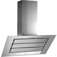
Ombre /2 800 Murale - Range hood ROBLIN - Free user manual and instructions
Find the device manual for free Ombre /2 800 Murale ROBLIN in PDF.


| Product type | Wall-mounted hood |
| Brand | Roblin |
| Model | Ombre /2 800 Wall-mounted |
| Width | 80 cm |
| Depth | 50 cm (estimate) |
| Height | 55 cm (estimate) |
| Net weight | 20 kg (estimate) |
| Power supply | 220-240 V, 50 Hz |
| Extraction power | Up to 600 m³/h (estimate) |
| Noise level | 45-65 dB (estimate) |
| Lighting | Integrated LED |
| Controls | Touch or button (depending on version) |
| Grease filters | Dishwasher safe |
| Charcoal filters | Optional, replace regularly |
| Exhaust type | Recirculation or external exhaust |
| Special functions | Automatic shutdown, timer, remote control (depending on version) |
| Maintenance and cleaning | Clean filters regularly, surface with a soft cloth |
| Safety | Automatic shutdown in case of overheating |
| Spare parts | Filters, LED bulbs, remote control |
| Warranty | 2 years (standard) |
Frequently Asked Questions - Ombre /2 800 Murale ROBLIN
User questions about Ombre /2 800 Murale ROBLIN
0 question about this device. Answer the ones you know or ask your own.
Ask a new question about this device
Download the instructions for your Range hood in PDF format for free! Find your manual Ombre /2 800 Murale - ROBLIN and take your electronic device back in hand. On this page are published all the documents necessary for the use of your device. Ombre /2 800 Murale by ROBLIN.
USER MANUAL Ombre /2 800 Murale ROBLIN
Libretto di Istruzioni Instructions Manual Manuel d'Instructions Bedienungsanleitung Gebruiksaanwijzing
INDICE
IT
CONSIGLI E SUGGERIMENTI....3
CARATTERISTICHE......4
INSTALLAZIONE 6
USO....9
MANUTENZIONE 11
INDEX
EN
RECOMMENDATIONS AND SUGGESTIONS 14
CHARACTERISTICS 15
INSTALLATION....17
USE 20
MAINTENANCE 22
SOMMAIRE
FR
CONSEILS ET SUGGESTIONS....25
CARACTERISTIQUES....26
INSTALLATION....28
UTILISATION 31
ENTRETIEN 33
INHALTSVERZEICHNIS
DE
Componenti
Connessioni
USCITA ARIA VERSIONE ASPIRANTE
CONNESSIONE ELETTRICA
Montaggio Camino
Camino superiore
Quadro comandi Telecomando


Illuminazione
RECOMMENDATIONS AND SUGGESTIONS
The Instructions for Use apply to several versions of this appliance. Accordingly, you may find descriptions of individual features that do not apply to your specific appliance.
INSTALLATION
- The manufacturer will not be held liable for any damages resulting from incorrect or improper installation.
- The minimum safety distance between the cooker top and the extractor hood is 650 mm (some models can be installed at a lower height, please refer to the paragraphs on working dimensions and installation).
- Check that the mains voltage corresponds to that indicated on the rating plate fixed to the inside of the hood.
- For Class I appliances, check that the domestic power supply guarantees adequate earthing.
Connect the extractor to the exhaust flue through a pipe of minimum diameter 120 mm. The route of the flue must be as short as possible. - Do not connect the extractor hood to exhaust ducts carrying combustion fumes (boilers, fireplaces, etc.).
- If the extractor is used in conjunction with non-electrical appliances (e.g. gas burning appliances), a sufficient degree of aeration must be guaranteed in the room in order to prevent the backflow of exhaust gas. The kitchen must have an opening communicating directly with the open air in order to guarantee the entry of clean air. When the cooker hood is used in conjunction with appliances supplied with energy other than electric, the negative pressure in the room must not exceed 0,04 mbar to prevent fumes being drawn back into the room by the cooker hood.
- In the event of damage to the power cable, it must be replaced by the manufacturer or by the technical service department, in order to prevent any risks.
USE
- The extractor hood has been designed exclusively for domestic use to eliminate kitchen smells.
- Never use the hood for purposes other than for which it has been designed.
- Never leave high naked flames under the hood when it is in operation.
- Adjust the flame intensity to direct it onto the bottom of the pan only, making sure that it does not engulf the sides.
- Deep fat fryers must be continuously monitored during use: overheated oil can burst into flames.
- Do not flambè under the range hood; risk of fire
- This appliance is not intended for use by persons (including children) with reduced physical, sensory or mental capabilities, or lack of experience and knowledge, unless they have been given supervision or instruction concerning use of the appliance by a person responsible for their safety.
- Children should be supervised to ensure that they do not play with the appliance.
- “CAUTION: Accessible parts may become hot when used with cooking appliances.”
MAINTENANCE
- Switch off or unplug the appliance from the mains supply before carrying out any maintenance work.
- Clean and/or replace the Filters after the specified time period (Fire hazard).
- Clean the hood using a damp cloth and a neutral liquid detergent.
The symbol 📋 on the product or on its packaging indicates that this product may not be treated as household waste. Instead it shall be handed over to the applicable collection point for the recycling of electrical and electronic equipment. By ensuring this product is disposed of correctly, you will help prevent potential negative consequences for the environment and human health, which could otherwise be caused by inappropriate waste handling of this product. For more detailed information about recycling of this product, please contact your local city office, your household waste disposal service or the shop where you purchased the product


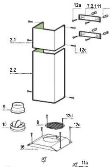
Components
| Ref. | Q.ty | Product components |
| 1 | 1 | Cooker hood with control unit, lights, blower unit, filters |
| 2.1 | 1 | Upper chimney |
| 2.2 | 1 | Lower chimney |
| 8 | 1 | Air outlet grid |
| 9 | 1 | Reducer flange ∅ 150-120 |
| 10 | 1 | Damper |
| 16 | 1 | Cover for recycling version |
Ref. Q.ty Installation components
| 7.2.1 2 Fixing brackets for upper chimney | ||
| 11 | 5 | Plugs |
| 11a | 2 | Plugs SB 12/10 |
| 12a | 5 | Screws 4,2 x 44,4 |
| 12c | 10 | Screws 2,9 x 6,5 |
| 12e | 2 | Screws 2,9 x 9,5 |
| Q.ty | Documentation |
| 1 | Instruction booklet |

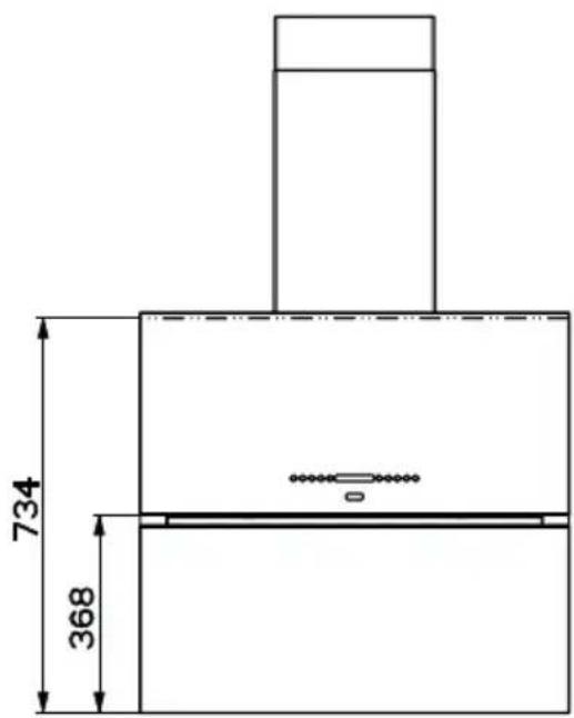
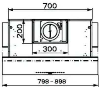
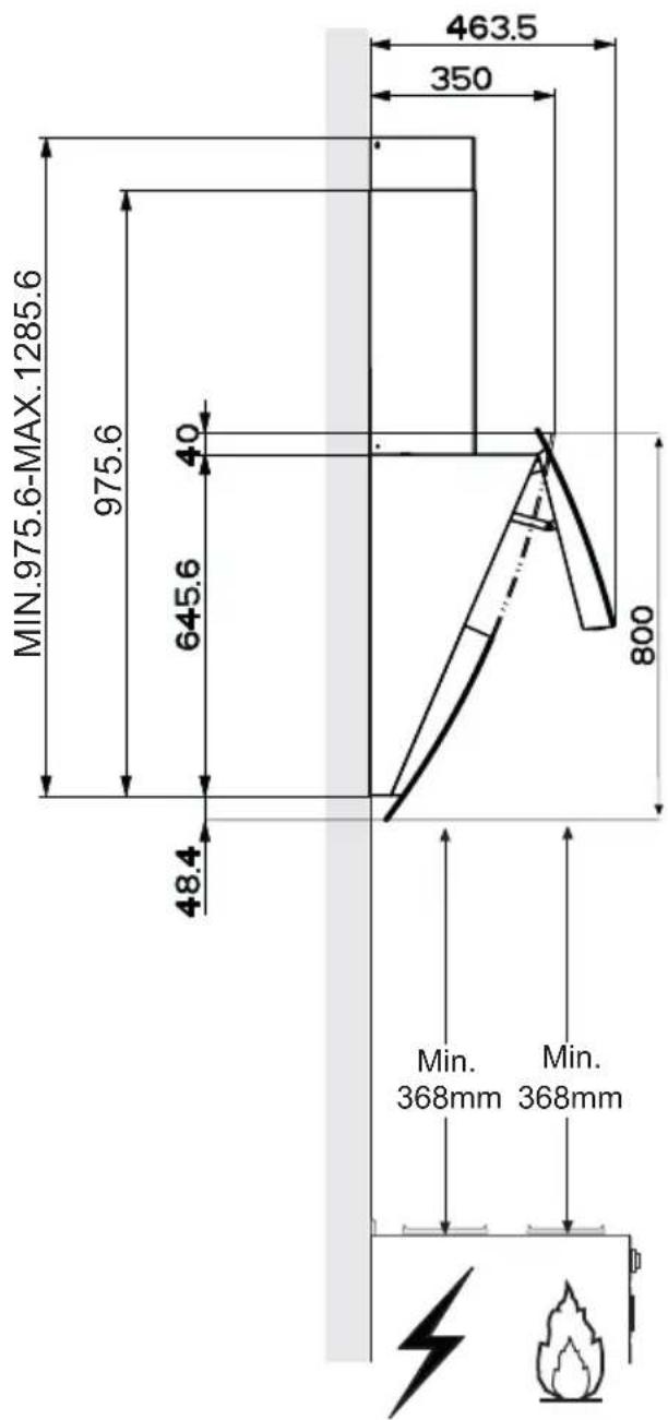
Wall drilling and bracket fixing
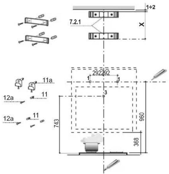
As a first step, proceed with the following drawings:
- a vertical line up to the ceiling or up to the upper limit, at the centre of the area in which the hood is to be fitted;
- a horizontal line at a minimum 960 mm above the cooker top.
- Mark a point (1) on the horizontal line, 292 mm to the right of the vertical reference line.
- Repeat this operation on the other side, checking that the two marks are levelled.
- Mark a reference point (3) at 743 mm above the cooker top on the vertical reference line.
- Drill at the marked points (1), using a φ 12 mm drill bit.
- Drill at the marked point(3), using a φ 8 mm drill bit.
- Insert the bracket plugs 11a into the holes (1) and tighten the screws.
- Insert plug 11 into hole (3).
- Place bracket 7.2.1 on the wall, about 1 - 2mm from the ceiling or from the upper limit, aligning the centre (notch) with the vertical reference line.
• Mark the wall at the centres of the bracket holes. - Place the bracket 7.2.1 on the wall at X mm below the first bracket (X = height of the upper chimney section), aligning the centre (notch) with the vertical line.
• Mark the wall at the centres of the bracket holes. - Drill φ 8 mm holes at all the marked centre points.
- Insert the wall plugs 11 in the holes.
- Fix the brackets using the 12a screws (4,2 x 44,4) supplied with the hood.
Hood body mounting
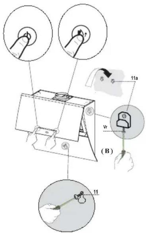
- Firstly, it is necessary to adjust the two Vr-screws of the 11a-brackets, at minimun (B).
- Hang the hood body on the two brackets 11a.
- Connect the hood to the mains supply by means of a bipolar switch with at least 3 mm contact gap.
- Press the “A”-key for one second (see Part USE) to open the upper panel.
- Remove the metal filters.
- In order to align the hood it is necessary to adjust the Vr-screws from inside the hood.
- Fasten the safety screw 11.
- Fit again the metal filters into their seats and close the upper panel by pressing “L”-key for one second (see Part USE).
- Disconnect the hood from the mains supply.
Attention: the upper panel stops if any barrier occurs in its way during the panel opening or closing. To open the panel it is enough to remove the barrier and press the key once again.
Connections
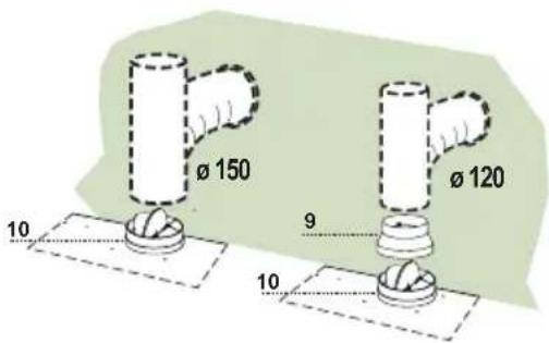
DUCTED VERSION AIR EXHAUST SYSTEM
When installing the ducted version, connect the hood to the chimney using either a flexible or rigid pipe 150 or 120mm, the choice of which is left to the installer.
To install a ø 150 pipe
• To install the dumper 10
- Fix the pipe in position using sufficient pipe clamps (not supplied).
To install a ø 120 pipe
- To install a 120 mm air exhaust connection, insert the reducer flange 9 on the dumper 10.
- Fix the pipe in position using sufficient pipe clamps (not supplied).
- Remove any activated charcoal filters.
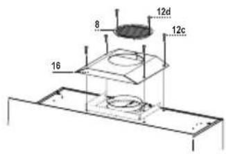
RECYCLING VERSION AIR OUTLET
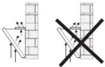
To install the hood in recycling version, the optional charcoal filter kit must be purchased.
- Remove the chimney angle bracket.
- Screw the filter cover onto the air outlet, using four screws 12c (2.9 x 12.5).
- Fix the air outlet grid 8 on the recirculation air outlet using the 2 screws 12d (2,9 x 9,5) provided.

ELECTRICAL CONNECTION
- Connect the hood to the mains supply.
- Open the upper panel by pressing the A-key (See Part "USE") for at least 2 seconds.
- Remove the metal filters (See Part “MAINTENANCE”) and make sure that the connector piece of the supply cable is correctly inside the hood socket.

Chimney assembly
Upper exhaust Chimney
- Slightly widen the two sides of the upper chimney and hook them behind the brackets 7.2.1, making sure that they are well seated.
- Secure the sides to the brackets using the 4 screws 12c (2,9 x 9,5) supplied.
Lower exhaust Chimney
- Slightly widen the two sides of the chimney and hook them between the upper chimney and the wall, making sure that they are well seated.
- Fix the lower part laterally to the hood body using the 2 screws 12c (2,9 x 9,5) supplied.

Control panel
| A | B | C | D | E |
| Button | Function Display | |
| A Door | Closed: Press and hold for approximately 2 Seconds to open the door and turn the motor on at the last speed set. Door Open: Press briefly to turn the motor Off or On. | Displays the set speed. |
| B | Decrease the working speed. | The number of lighted segments decreases. |
| C | Increase the working speed. | The number of lighted segments increases. |
| D Can | only be activated with Door Open. This speed is timed to run for 10 minutes. At the end of this time the system will automatically return to the speed set before. Suitable to deal with maximum levels of cooking fumes. | The indicator I flashes and all the segments on the Display are lit. It is disabled by pressing the Button. |
| E Can | only be activated with Door Open. Starts the Motor at a speed that allows suction of 100 m3/h. Cannot be activated if Intensive or Delay are active. | Displays 24 and the segments on the Display all light up and then turn off one at a time in cycle. It is disabled by pressing the Button. |
| F Can | be activated with motor on (except for intensive and 24 mode). Activates automatic shutdown of the Motor and the Lighting with a 30' delay. | Displays a flashing Clock symbol. It is disabled by pressing the Button. |
| G | Performs a Reset of the Filter saturation alarm when the button is pressed for approximately 3 seconds when all the users (motor + lights) are turned off. | After 100 hours in operation the Drop symbol is displayed to indicate saturation of the Metal Grease Filters. After 200 hours in operation the letter C is displayed to indicate saturation of the Activated Charcoal filters. |
| H | Modifies the intensity of the Lighting each time the Button is pressed, in cycle. | |
| I Door Closed: When pressed and held for approximately 2 seconds opens the door half way and turns the lighting on to maximum intensity. The intensity can be modified using button H. - When the button is pressed again, the lighting turns off and the door closes. - Press L for door fully open, motor at speed three and lighting on. - When button A is pressed the lights turn on and the motor operates at the first two speeds only. Door Open: Press briefly to turn the lighting On or Off. | ||
| L Door | Closed: Press and hold for approximately 2 Seconds to open the door, turn the motor on at speed three and turn the lighting on at maximum intensity. Door Open: When pressed and held for approximately 2 seconds turns off the motor and the lighting, cancelling any function that may be active and closing the door. |
Keyboard Lock: it is possible to lock the keyboard, for example when cleaning the Glass, when the Hood has Motor and Lights turned off and when no alarms have been triggered.
Press F (Delay) for approximately 5 Seconds to enable or disable the Keyboard Lock, which is always confirmed by a Beep and an animation on the display motor bar.
REMOTE CONTROL
The appliance can be controlled using a remote control powered by a 1.5 V carbon-zinc alkaline batteries of the standard LR03-AAA type (not included).
- Do not place the remote control near to heat sources.
• Used batteries must be disposed of in the proper manner.

Remote control panel

| Motor Door Door Open | Closed: Opens the door and turns the motor on at the last speed set. | |
| Motor On / Off | ||
| Pressed for 2 Seconds:a) If the door is open, Motor + Lights Off.b) If the door is closed, Opens the door and Lights + Motor On. | ||
| - | Decreases | the working speed each time it is pressed. |
| + | Increases the working speed each time it is pressed. | |
| i | Intensive | Activates the Intensive function |
| ◎ | Delay Activates the Delay function | |
| Pressed for | 2 Seconds: Activates / Deactivates the 24H function | |
| Light | Door Closed: Opens the door half way and turns the Lights on a Maximum Intensity. | |
| Door open | half way: Turns lights off and closes the door. | |
| Door Open | Lights On / Off | |
Metal grease filters
Filters can be washed in the dish machine. They need to be washed when Drop-sign appears on the display or in any case every 2 months, or even more frequently in case of particularly intensive use of the hood.
Alarm reset
- Press the G-key for at least 2 seconds.
Cleaning the filters
- Open the upper panel by pressing the A-key for 1 second (see Part USE).
- Remove the filters one by one pushing them towards the back side of the hood unit and simultaneously pulling downwards.
- Any kind of bending of the filters has to be avoided when washing them. Before fitting them again into the hood make sure that they are completely dry. (The colour of the filter surface may change throughout the time but this has no influence to the filter efficiency).
- When fitting the filters into the hood pay attention that they are mounted in correct position the handle facing outwards.
This cannot be washed or regenerated, and must be changed when the C symbol on the display appears, or at least once every 4 months. The Alarm signal must be activated in advance.
Activating the alarm signal
- In Recirculation Version Hoods, the Filter Saturation Alarm must be activated on installation or at a later date.
- Turn the Lights and the Suction Motor off.
- Press button E for approximately 5 seconds until an animation lights up on the Display. The “Clock” icon flashes.
- Within 5 seconds, press D to enable / disable the A.C. Filters
- Symbol C lights up, A.C. Filter saturation alarm ACTIVATED
- Symbol C turns off, A.C. Filter saturation alarm DEACTIVATED
REPLACING THE CHARCOAL FILTER
Alarm reset
- Press the G-key for at least 2 seconds.
Replacing the filter
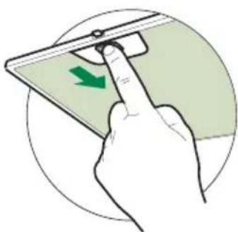
- Open the upper panel by pressing the A-key for about a second (see Part USE).
- Remove the metal filters.
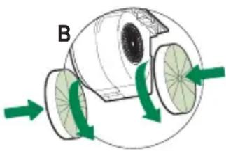
- Remove the saturated charcoal filter as indicated (A).
• Fit the new filters as indicated (B). - Put the metal grease filters in their seats.

Lighting unit
REPLACING OF THE LED UNIT
LED
- To remove the lighting unit a screwdriver can be used in order to slightly press the side part of the unit.
- Remove the unit, remove the electrical connector and replace the unit with a new one. ("To purchase contact technical support")
Warning: This appliance is fitted with a white LED lamp classed as 1M according to EN 60825-1: 1994 + A1:2002 + A2:2001 standards; maximum optical power emitted @439nm: 7μW. Do not look directly at the light through optical devices (binoculars, magnifying glasses...).
Replacing the fuser
- The fuser is placed up on the right side. Turn the fuser holder as indicated. Replace the fuser with one having the same features.

CONSEILS ET SUGGESTIONS
CARACTERISTIQUES
Composants
Branchements
SORTIE AIR VERSION ASPIRANTE
BRANCHEMENT ÉLECTRIQUE
Montage Cheminée
Cheminée supérieure
REEMPLACEMENT DU FILTRE ANTI-ODEUR AU CHARBON ACTIF

Éclairage
REMPLACEMENT DES AMPOULES
Spot à DEL
Komponenten
Anschlüsse
ELEKTROANSCHLUSS
Kaminmontage
Oberer Kaminteil

Beleuchtung
AUSWECHSELN DER LAMPE
LED-Strahler
ADVIEZEN EN SUGGESTIES
Onderdelen
Aansluitingen
LUCHTUITLAAT AFZUIGVERSIE

Verlichting
VERVANGEN VAN DE LAMPEN
Ledlampje
CE


- INDICE
- IT
- INDEX
- EN
- SOMMAIRE
- FR
- INHALTSVERZEICHNIS
- DE
- COMPONENTI
- CONNESSIONI
- USCITA ARIA VERSIONE ASPIRANTE
- CONNESSIONE ELETTRICA
- MONTAGGIO CAMINO
- CAMINO SUPERIORE
- QUADRO COMANDI TELECOMANDO
- ILLUMINAZIONE
- RECOMMENDATIONS AND SUGGESTIONS
- INSTALLATION
- USE
- MAINTENANCE
- WALL DRILLING AND BRACKET FIXING
- HOOD BODY MOUNTING
- CONNECTIONS
- DUCTED VERSION AIR EXHAUST SYSTEM
- TO INSTALL A Ø 150 PIPE
- TO INSTALL A Ø 120 PIPE
- RECYCLING VERSION AIR OUTLET
- ELECTRICAL CONNECTION
- CHIMNEY ASSEMBLY
- UPPER EXHAUST CHIMNEY
- LOWER EXHAUST CHIMNEY
- REMOTE CONTROL
- REMOTE CONTROL PANEL
- METAL GREASE FILTERS
- ALARM RESET
- CLEANING THE FILTERS
- ACTIVATING THE ALARM SIGNAL
- REPLACING THE CHARCOAL FILTER
- REPLACING THE FILTER
- LIGHTING UNIT
- REPLACING OF THE LED UNIT
- LED
- REPLACING THE FUSER
- CONSEILS ET SUGGESTIONS
- CARACTERISTIQUES
- COMPOSANTS
- BRANCHEMENTS
- SORTIE AIR VERSION ASPIRANTE
- BRANCHEMENT ÉLECTRIQUE
- MONTAGE CHEMINÉE
- CHEMINÉE SUPÉRIEURE
- REEMPLACEMENT DU FILTRE ANTI-ODEUR AU CHARBON ACTIF
- ÉCLAIRAGE
- REMPLACEMENT DES AMPOULES
- SPOT À DEL
- ANSCHLÜSSE
- ELEKTROANSCHLUSS
- KAMINMONTAGE
- OBERER KAMINTEIL
- BELEUCHTUNG
- AUSWECHSELN DER LAMPE
- LED-STRAHLER
- ADVIEZEN EN SUGGESTIES
- AANSLUITINGEN
- LUCHTUITLAAT AFZUIGVERSIE
- VERLICHTING
- VERVANGEN VAN DE LAMPEN
- LEDLAMPJE
Brand : ROBLIN
Model : Ombre /2 800 Murale
Category : Range hood