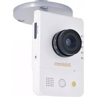
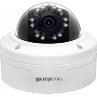
WCB-202AP - Surveillance Camera Brickcom - Free user manual and instructions
Find the device manual for free WCB-202AP Brickcom in PDF.


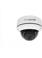
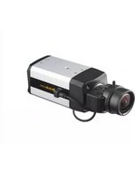
| Product Type | IP Surveillance Camera |
| Model | WCB-202AP |
| Brand | Brickcom |
| Image Sensor | 1/2.7-inch CMOS |
| Resolution | 2 Megapixels (1920x1080) |
| Lens | Fixed 4mm, F1.8 |
| Night Vision | Up to 30m with IR LEDs |
| Video Compression | H.265, H.264, MJPEG |
| Dimensions | 180 x 70 x 70 mm |
| Weight | 550 g |
| Power Supply | DC 12V 1A or PoE (802.3af) |
| Power Consumption | Max 6W |
| Network Interface | 10/100Mbps Ethernet |
| Wireless | Wi-Fi 802.11b/g/n (optional) |
| Storage | MicroSD slot up to 128GB, NVR, Cloud |
| Motion Detection | Yes, with email/APP alerts |
| Audio | Built-in microphone and speaker |
| Ingress Protection | IP67 (weatherproof) |
| Operating Temperature | -30°C to 60°C |
| Compliance | CE, FCC, RoHS |
| Mounting | Wall or ceiling mount included |
| Included Accessories | Power adapter, mounting kit, quick guide |
Frequently Asked Questions - WCB-202AP Brickcom
User questions about WCB-202AP Brickcom
0 question about this device. Answer the ones you know or ask your own.
Ask a new question about this device
Download the instructions for your Surveillance Camera in PDF format for free! Find your manual WCB-202AP - Brickcom and take your electronic device back in hand. On this page are published all the documents necessary for the use of your device. WCB-202AP by Brickcom.
USER MANUAL WCB-202AP Brickcom
Megapixel Cube Network Camera
CB-100A/CB-500A Series
User's Manual
Quality Service Group
Product name: Network Camera (CB-100A/CB-500A series)
Release Date: 2013/7
Manual Revision: V2.3
Web site: www.brickcom.com
Email: support@brickcom.com
info@brickcom.com
©2013 Brickcom Corporation. All Rights Reserved
Table of Contents
Before You Use This Product....0
FCC Warning 0
Regulatory Information.... 1
Product Comparison 0
Package Contents....0
Cube Network Camera Overview.... 2
Device Appearance Description 4
LED Behavior....7
Installation....9
System Requirements 9
Camera Connection 10
Basic Connection 10
Software Installation 12
EasyConfig 19
Accessing the Network Camera 28
Check Network Settings 28
Add Password to Prevent Unauthorized Access 28
Authentication.... 28
Installing the Plug-In....29
Live View....30
Configuration.... 33
Camera/Video/Audio 33
Camera 33
Video....35
Audio....39
Multicast....40
Privacy Mask Control....41
Enabling De-warp Function For Camera 42
Network 52
IP Settings 52
UPnP 54
DDNS (dynamic domain name service) 55
Brickcom
EasyLink™ 56
Wireless 58
HTTP/HTTPS 64
Event 67
Event Settings 67
Motion Detection 71
PIR(*)....72
Audio Detection 72
Notifications....73
FTP Settings 73
E-mail Settings 74
Samba Settings 74
HTTP Settings 75
Video Clip 76
Audio Clip(*) 77
LED Light(*) 78
System 79
System Log 79
Date and Time 80
Device Information 81
Storage Management(*) 83
LED Indicators 84
Maintenance....86
User Management 86
Language 87
IP Filter 87
Firmware Upgrade 88
Configuration 88
Reset to Default 89
Reboot 89
Brickcom
Before You Use This Product
In many countries, there are laws prohibiting or restricting the use of surveillance devices. This Network Camera is a high-performance, web-ready camera which can be part of a flexible surveillance system. It is the user's responsibility to ensure that the operation of this camera is legal before installing this unit for its intended use.
Upon opening the product's package, verify that all the accessories listed on the "Package Contents" are included. Before installing the Network Camera, read the warnings in the "Quick Installation Guide" to avoid misuse. When installing the Network Camera, carefully read and follow the instructions in the "Installation" chapters to avoid damages due to faulty assembly or installation.
FCC Warning
This device complies with Part 15 of FCC rules.
Operation is subject to the following two conditions;
(1) This device may not cause harmful interference, and
(2) This device must accept any interference received, including interference that may cause undesired operations.
Brickcom
Regulatory Information
Federal Communication Commission Interference Statement
This equipment has been tested and found to comply with the limits for a Class B digital device, pursuant to Part 15 of the FCC Rules. These limits are designed to provide reasonable protection against harmful interference in a residential installation. This equipment generates uses and can radiate radio frequency energy and, if not installed and used in accordance with the instructions, may cause harmful interference to radio communications. However, there is no guarantee that interference will not occur in a particular installation. If this equipment does cause harmful interference to radio or television reception, which can be determined by turning the equipment off and on, the user is encouraged to try to correct the interference by one of the following measures:
- Reorient or relocate the receiving antenna.
- Increase the separation between the equipment and receiver.
- Connect the equipment into an outlet on a circuit different from that to which the receiver is connected.
- Consult the dealer or an experienced radio/TV technician for help.
FCC Caution: Any changes or modifications not expressly approved by the party responsible for compliance could void the user's authority to operate this equipment.
This device complies with Part 15 of the FCC Rules. Operation is subject to the following two conditions: (1) This device may not cause harmful interference, and (2) this device must accept any interference received, including interference that may cause undesired operation.

IMPORTANT NOTE:
FCC Radiation Exposure Statement:
This equipment complies with FCC radiation exposure limits set forth for an uncontrolled environment. This equipment should be installed and operated with minimum distance 20cm between the radiator & your body.
This transmitter must not be co-located or operating in conjunction with any other antenna or transmitter.
The availability of some specific channels and/or operational frequency bands are country dependent and are firmware programmed at the factory to match the intended destination.
The firmware setting is not accessible by the end user.
Product Comparison
| Model Name Lens | Resolution DI/DO | WiFi | PoE | USB port for 3G/4G | ||
| CB-100A Series | CB-100Ap | Board Lens | 1280x800 | - | - - | - |
| WCB-100Ap | Board Lens | ✓ | - - | |||
| CB-101Ap V2.1 | Board Lens | (1/1) | - | ✓ ✓ | ||
| CB-102Ap V2.1 | CS Mount | - | ✓ ✓ | |||
| CB-500A Series | CB-500Ap | Board Lens | 2592 x 1944 pixel | (1/1) | - | ✓ ✓ |
| WCB-500Ap | Board Lens | ✓ | - - | |||
| CB-502Ap | CS Mount | - | ✓ ✓ | |||
| WCB-502Ap | CS Mount | ✓ | - - | |||
| CB-500A-360 Series | CB-500Ap 360p-L | Panomorph Lens | 2592 x 1944 pixel | (1/1) | - | ✓ ✓ |
Brickcom
Package Contents
Please check to make sure the product package contains all the accessories listed below.
a. Network Camera 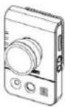  | b. Product CD |
c. Camera Stand d. Warranty Card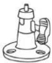  |  |
| e. Terminal I/O Connector Block (*)(H7YZ) | f. Easy Installation Guide |
g. 1.5m White Flat RJ-45 cable(For CB-100Ae/ CB-100Ap only) | h. Power Adapter (*)(DKTA) |

NOTE - (*) These are optional features. Please refer to the Product List
for the full list of optional features that are available for this product.
Brickcom
Cube Network Camera Overview
The compact Brickcom CB-100A/CB-500A series Cube network series offers a high quality, video surveillance solution for residences and small businesses. Unlike a general webcam, this camera series is a standalone surveillance system that does not need to be connected to a computer. EasyLink™ is a feature of the CB-100A/CB-500A series camera which allows for users to simply plug in the camera to any home or small business network and play the video.
This camera series offers a user-friendly and unique design which allows anyone without a technical background to use it. It features live video feed and two-way audio which can be used over a local area network (LAN), through any internet browser, or via any 3G mobile device. The wireless capability makes it easy to mount on any surface. The CB-100A/CB-500A series features many cutting edge functions and its fashionable, streamline design make it the perfect additional for any home or office.
Because of its many advanced features, the CB-100A/CB-500A series has many versatile applications. Users can easily monitor the safety of their family members, pets, office, valuables, and property.

Small Office Surveillance –
Security systems for small offices can be expensive and difficult to install and maintain. With the EasyConfig software, the CB-100A/CB-500A series can easily be installed and configured by anyone without extensive technical knowledge. The video can be reviewed remotely so business owners can monitor office safety and employee productivity at all times.

Residence monitor –
Home owners worry about their house and property when they are away. The CB-100A/CB-500A series has a built-in PIR sensor which can detect unauthorized movement in a residence. Once movement is detected, the illumination LED will be triggered and an alert with a snapshot can be emailed or sent through an MMS to the user's portable device.

Elderly and Child Care –
A high concern for many people is the safety of elderly relatives and small children. Users can use the CB-100A/CB-500A series camera to ensure the safety of their loved ones by use of the live view and intercom functions.
Brickcom
Pet Monitor –
The motion detection feature can be used to create forbidden areas in the home which the pet should not enter when the owner is away. If the camera records the pet entering the region, a recorded message can be programmed to play and the owner will be notified via email or MMS.
![graph TD A["Internet"] --> B["3G Phone"] A --> C["3G Network"] A --> D["AP/Router"] A --> E["CB-100A"] A --> F["CB-100A"] A --> G["Pet Monitor"] A --> H["Elderly and Child Care"] A --> I["Residence monitor"] A --> J["Small Office Surveillance"] B --> K["3G Network"] C --> L["AP/Router"] D --> M["CB-…](/content/2026/06/1256506/images/68783a0e597a922eb00c680cbc1d5430195abc8bf3a8ce42730d7271340281f1.jpg)
Device Appearance Description
CB-100A Series/CB-500A Series
< Front & Rear view >

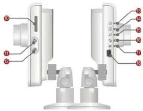
1 Adjustable focal Lens (*)
② Built-in Microphone
③ PIR (*)
4 Illumination LED
5 Speaker (*)
6 Power Connector
7 Ethernet RJ45 Socket
8 Reset Button
9 DIDO Terminal I/O Connector (*)
10 Micro SD/SDHC slot (*)
11 WPS button (*)
12 Privacy button
13 Power LED
14 Status LED
15 Internet LED
16 WPS LED (*)
17 Privacy LED
18 USB Port for 3G/4G (*)

Brickcom
Device Appearance Description
- CB-500Ap-360p-L
< Front & Rear view >

1 Adjustable focal Lens (*)
② Built-in Microphone
3 PIR (*)
4 Illumination LED
⑤ Speaker (*)
6 Power Connector
⑦ Ethernet RJ45 Socket
8 Reset Button
9 DIDO Terminal I/O Connector (*)
10 Micro SD/SDHC slot (*)
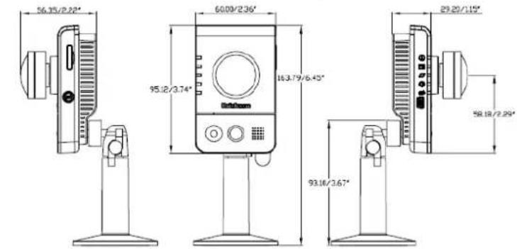
11 Privacy button
12 Power LED
13 Status LED
14 Internet LED
15 FW Upgrade Led
16 Privacy LED
17 USB Port for 3G/4G
Brickcom
-
NOTE - The WPS and Privacy buttons must first be enabled through the web GUI in order to work. See page 37 for details on how to enable the Privacy button and see page 50 for details on how to enable the WPS Button.
-
(*) These are optional features. Please refer to the Product List for the full list of optional features available for the product.
Brickcom
LED Behavior
| Function LED Behavior Description Remark | |||
| Power Continuous Illumination Normal Operation Top | (Blue) | ||
| Power Unlit | Powered off Top | (Blue) | |
| Status | Continuous Illumination | 1. Connected to switch by Ethernet or WiFi. | Second (Blue) |
| Status | Unlit | 1. Powered off2. No connection | Second (Blue) |
| Status | Blinking | 1. Data Transmission via WiFi or Ethernet | Second (Blue) |
| Internet | Continuous Illumination | Connected to Internet | Third (Blue) |
| Internet | Unlit | 1. Powered off2. No connection | Third (Blue) |
| WPS | Blinking | WPS in progress | WCB-100A/C B-500A SERIES Fourth (Blue) |
| WPS | Continuous Illumination | WPS success | WCB-100A/C B-500A SERIES Fourth (Blue) |
| Firmware Upgrade | Blinking | Under FW upgrade Process | WCB-100A/C B-500A SERIES Fourth (Blue) |
| Firmware Upgrade | Continuous Illumination | Firmware successfully upgraded | CB-100A/CB-5 00A SERIES Fourth (Blue) |
| Privacy | Continuous Illumination | Privacy mask active | Bottom(Red) |
| Privacy | Unlit | Privacy mask inactive | Bottom(Red) |
Brickcom
Hardware Reset
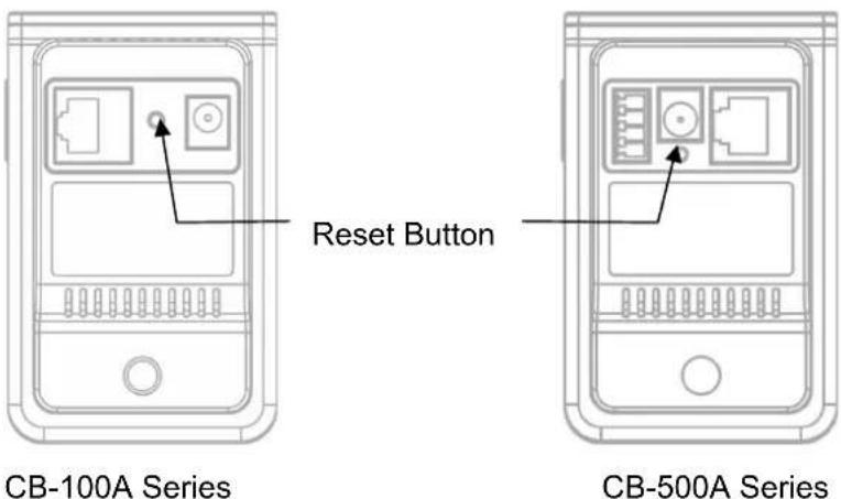
The Reset Button can be used to reboot the camera or restore it to factory default settings. If the camera experiences a problem, rebooting the camera may correct the problem. If the problem remains, please restore the camera to factory default settings and reinstall the software.
To Reboot - Press and hold the Reset Button for one second using a paper clip or thin object. Wait for the camera to reboot.
To Restore – Press and hold the Reset Button for ten seconds until the LED light turns off. When successful restored, the LED will be blue during normal operation.

NOTE - By restoring the camera, all settings will be restored to the factory default settings.
Micro-SD/SDHC Card Capacity
The network camera is compatible with Micro-SD/SDHC (Maximum 32GB) cards.
Brickcom
Installation
System Requirements
Operating System:
Microsoft Windows XP Home Edition SP2
Microsoft Windows XP Professional SP2
Computer:
IBM PC/AT Compatible
CPU:
Pentium 3GHz or faster
Memory:
1024 MB or more
Monitor:
1024 x 768 pixels or more, 24-bit True color or better
Network Interface:
10/100Mbps Network interface card must be installed
Web Browser:
Microsoft Internet Explorer 6.0 SP2 or higher
Adobe Reader:
Adobe Reader 8.0 or higher
Audio:
The audio function will not work if a sound card is not installed in the PC. Audio may be interrupted depending on network traffic.
Brickcom
Camera Connection

Warning Hot – Please attach the bracket before using CB-500A Series.
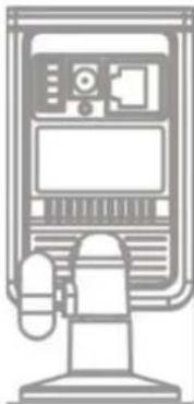
Terminal I/O Connector Block Connection
Attach the supplied connector block to the terminal connector on the camera. Refer to the diagram below to attach external devices to the connector block.

Basic Connection
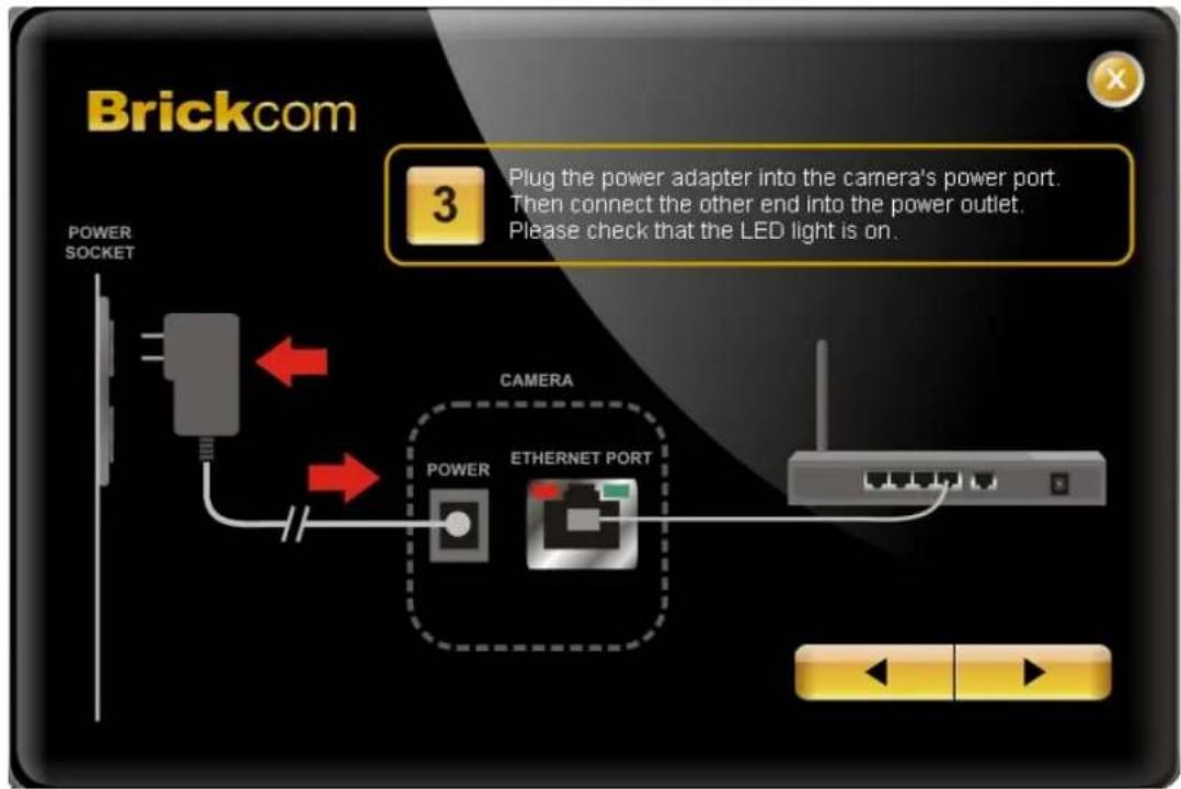
- Connect the supplied power cable from the camera to a power outlet.
- Connect the camera to a switch using an Ethernet cable.

CB-100A Series
Brickcom

CB-500A Series
When powering up, the power LED will light up and the camera will boot up. The status LED will turn amber when the camera is obtaining the IP address. After obtaining the IP address, the link LED will flash orange while the network connection is processing.
Brickcom
Software Installation
In this manual, "User" refers to whoever has access to the Network Camera, and "Administrator" refers to the person who can configure the camera and grant user access to the camera.
After checking the hardware connection, run the Installation Wizard program included on the product's CDROM to automatically search the intranet for the camera. There may be many cameras on the local network. Differentiate the cameras using the serial number which is printed on the labels on the carton and the bottom of the camera.
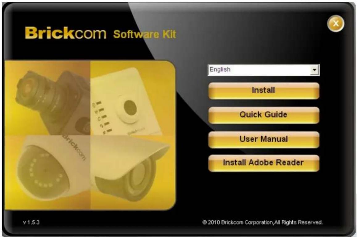
- Insert the Installation CD into the CD-ROM driver. Run Auto-Run Tool directly from the CD-ROM to start the installation. When installing the Brickcom software kit for the first time, select a desired language for the interface. The available languages are listed in the scroll box. Click
and follow the steps to install the EasyConfig wizard on the desired computer.
Brickcom
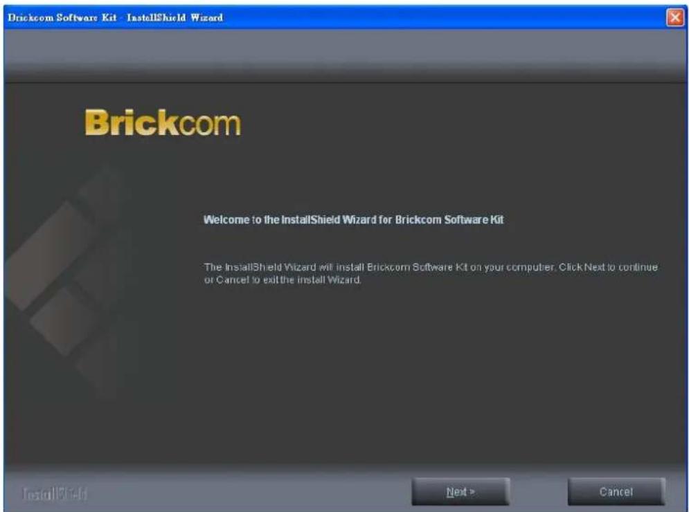
- In the Install Shield Wizard dialog box, click
to continue.
- Read the End-User License Agreement and check the option "I accept the terms of the license agreement". Click
to continue.

Brickcom
- Select either "Complete" setup or "Custom" setup to install the system.
a. If COMPLETE SETUP is selected:
i. All program features will be installed into the default directory. Check the option "Complete" and then click

ii. Select to create shortcuts. Click

iii. The installation information will be displayed. Click
![Brickcom Software Kit - InstallShield Wizard Please read the following text Current Settings [Setup Type] Complete [Select Features] EasyConfig PC-NVR Standard [Choose Destination Location] EasyConfig: C:\Program Files\Brickcom\EasyConfig PC-NVR Standard: C:\Program Files\Brickcom\PC-NVR Standard\Ex…](/content/2026/06/1256506/images/bef2b967885c085e34c06031c86380b4b2d67e8e89fbc6c13f01a7ecf82bf07f.jpg)
b. If CUSTOM SETUP is selected:
i. This option is recommended for advanced users. It can be used to install the system to a preferred directory or to select specific program feature(s).
ii. Check the option "Custom", and then click
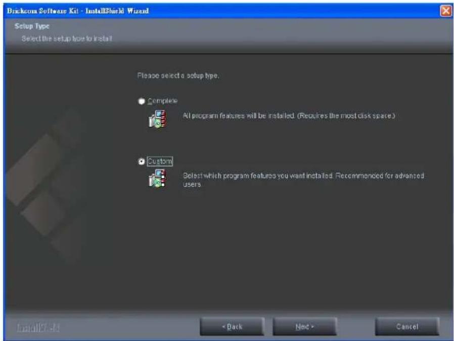
iii. Select the features to install. Click

iv. Click

v. Select programs to create shortcuts. Click

vi. The installation information will be displayed. Click
![Brickcom Software Kit - InstallShield Wizard Please read the following text Current Settings: [ Setup Type ] Custom [ Select Features ] EasyConfig PC-NVR Standard [ Choose Destination Location ] EasyConfig: C:\Program Files\Brickcom\EasyConfig PC-NVR Standard: C:\Program Files\Brickcom\PC-NVR Standa…](/content/2026/06/1256506/images/f1cf031010984032acf5f21466f242fcba6cf083c5d439ae11527b5c354d55a2.jpg)
Brickcom
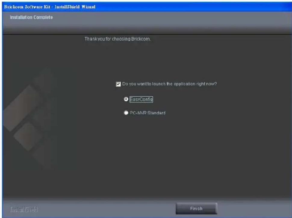
- To launch EasyConfig or PC-NVR Standard, select the application and click
. When launching the PC-NVR program, please refer to the PC-NVR user manual.
Brickcom
EasyConfig
To launch EasyConfig, select EasyConfig from the start menu. If Complete Setup type was used in the software installation, an EasyConfig icon was installed on the desktop. Double click to open the icon.
If Custom Setup type was used in the software installation and an EasyConfig icon was not installed on the desktop, the program will be installed under C:\Program Files\Brickcom\EasyConfig unless the program was saved to a preferred directory.
- Click
to continue. The program will automatically search for the camera in the intranet.

NOTE - Check "Skip the hardware installation guide" to skip checking the hardware connection. To check the hardware installation settings, do not check the option box.

Brickcom


Brickcom
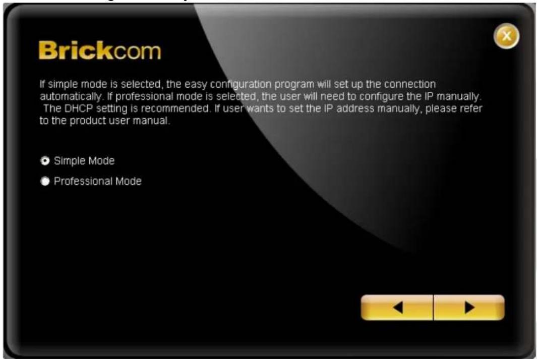
- Select either "Simple Mode" or "Professional Mode" to obtain the camera's IP settings. If "Simple Mode" is selected, EasyConfig will set up the connection automatically. If "Professional Mode" is selected, the user will need to configure the IP settings manually.
Brickcom
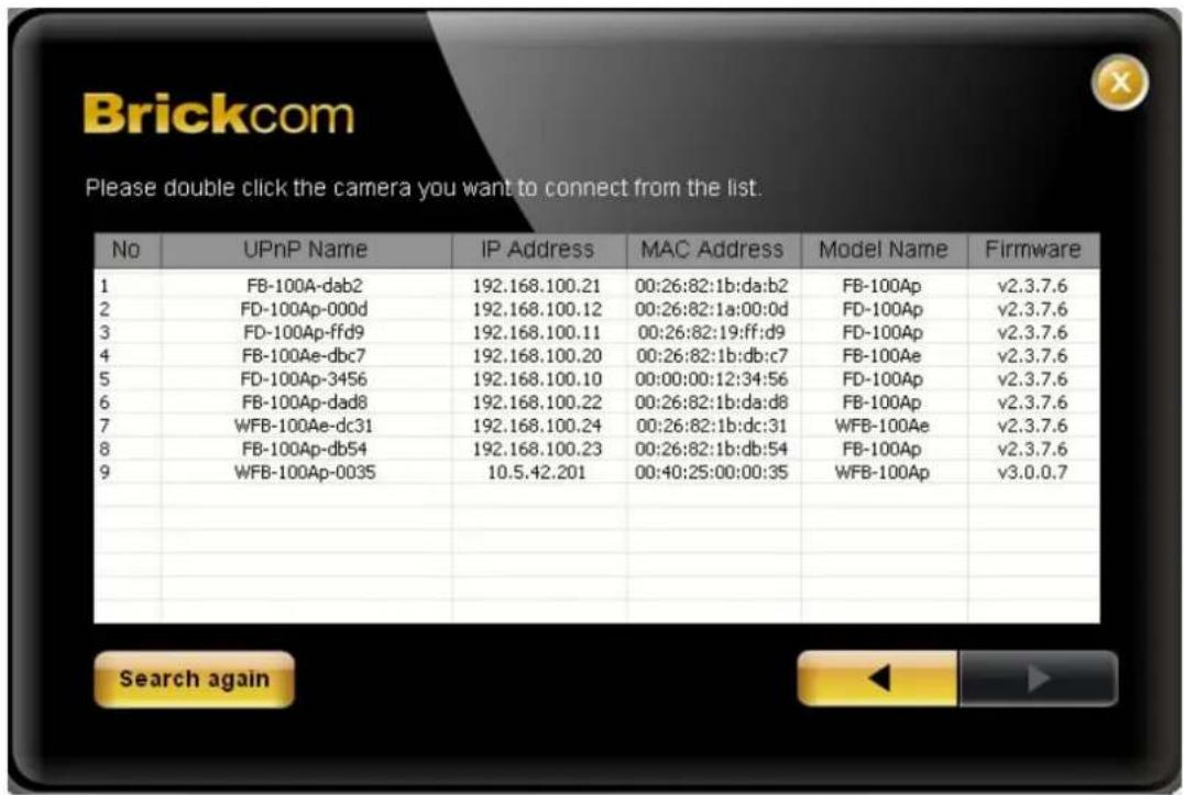
- There may be many cameras in the local network. Differentiate the cameras using their UPnP name. Double click on the camera from the survey list to connect.
- Enter the username and password of the camera. For first time use, the default username and password are "admin/admin."

Brickcom
- For configuring the IP address settings, select either
, or . The DHCP setting is recommended.
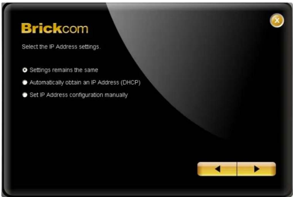
a. If

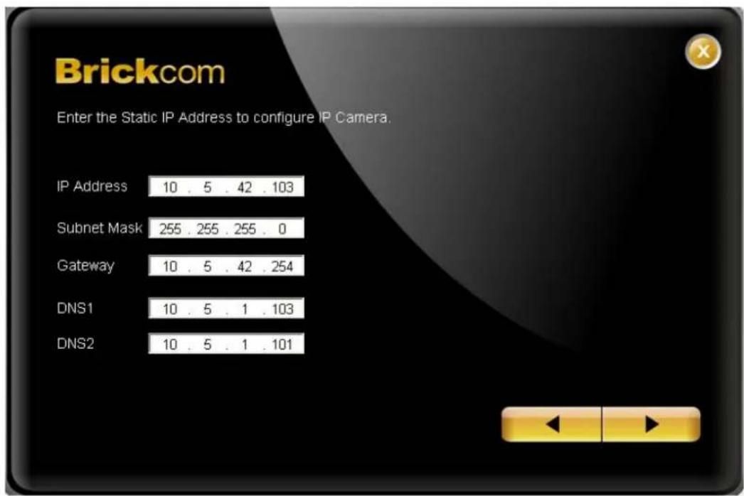
- If the camera supports the EasyLink™ function, the following page will be displayed. Otherwise, this page will not be shown. *If desired, click
to skip this setting.

Brickcom
EasyLink™ is a unique Brickcom function which allows users to assign a unique EasyLink name to their network camera's IP address. There is no need to configure the router to open up ports or remember hard-to-memorize IP addresses. When this feature is enabled, users can log onto [uniqueEasyLinkname].mybrickcom.com to view the camera's web GUI and live view.
- Enter a unique EasyLink name whose length must be between 5-32 characters.
- When finished, click the arrow button to continue.
- NOTE - See page 42 for more details about the EasyLink function.
Brickcom
- When the IP address settings have been configured, the screen will either display a successful or failed connection message. If the connection failed, either try again or quit the installation.
a. If "DHCP IP address settings" was selected, the failure page will be displayed as below:

b. If "Static IP address settings" was selected, the failure page will be displayed as below:

Brickcom
c. If the connection was successful, the user will see the message:
"Congratulations. The installation of the camera is complete."
When this window is displayed, click

Once installation is complete, the Administrator should proceed to the next section "Accessing the Network Camera" for necessary changes and configurations.
Brickcom
Accessing the Network Camera
Check Network Settings
The camera can be connected either before or immediately after the software installation. The Administrator should complete the network settings on the configuration page, including entering the correct subnet mask and IP address of gateway and DNS. Ask the network administrator or Internet service provider for the detail information.
Add Password to Prevent Unauthorized Access
The Administrator should immediately implement a new password as a matter of prudent security practice. For first time use, the user name and password for the Administrator are assigned as “admin/admin”. After the Administrator changes the Administrator password, the web browser will display an authentication window to confirm the new password. Once the password is set, there is no provision to recover the Administrator’s password. If the Administrator’s password is lost, the only option is to restore the original factory default settings.
The Administrator can set up a maximum of ten (10) user accounts. Users will be able to access the Network Camera, but will not be allowed to access system configurations.
Authentication
To access the camera's live view, open a web browser and enter the IP address of the camera. A dialog window will pop requesting a username and password. As stated on the previous page, for the default username and password for the Administrator are assigned as "admin/admin". For accounts other than the administrator's account, the user can choose to remember the password for future convenience. It is not recommended to check this box when viewing the camera feed from a public computer.

Brickcom
Installing the Plug-In
For the initial access to the camera in Windows, the web browser may prompt the administrator for permission to install a new plug-in for on Internet Explorer. Permission request depends on the Internet security settings of the user's PC or notebook. If the highest security level is set, the computer may prohibit any installation and execution attempt. This plug-in has been registered for certificate and is used to display the video in the browser. Click on to proceed. If the web browser does not allow the administrator to
continue the installation, check the Internet security option and lower the security levels or contact the networking supervisor or IT for help.

NOTE – If an error occurred or the plug-in fails to install, it is because the version of the
Electronic Signature is newly released and the VeriSign has not been submitted to Microsoft Windows update for validation. Therefore, plug-in will not have its root certificate. If IE discovers that there is no root certificate after the user's PC connects to the camera, it will automatically redirect to VeriSign Web site to download and install the latest root certificate to make the installation successfully. If the user's computer is able to connect to camera but unable to access the internet, then the installation will fail because the computer will not be able to download the latest root certificate. This problem can be resolved if computer can be connect to the internet and the camera at the same time and will not recur when Windows update patches become available.
Brickcom
Live View
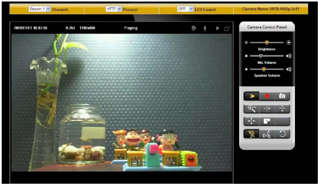

NOTE - (*) These are optional features. Please refer to the Product List for the full list of
optional features available for the product.
Live View is the default page that opens when accessing the camera. Live video is displayed directly in the browser window.
- Stream1/Stream2 Channels
The network camera offers simultaneous dual stream for optimized quality and bandwidth. Go to Configuration → Camera/Video/Audio → Video to configure the codec compression and video resolution or refer to the Video configuration page.
- HTTP/TCP/UDP protocol
HTTP – This unicast method can be used to traverse firewalls. Firewalls are commonly configured to allow the HTTP protocol, thus allowing RTP to be tunneled.
Brickcom
TCP - This protocol guarantees the complete delivery of streaming data and provides better video quality. The downside of using this protocol is that the quality of its real-time effect is less than that of the UDP protocol.
UDP - This protocol allows for more real-time audio and video streams. However, network packets may be lost due to network burst traffic and images may be broken. Activate UDP connection time-sensitive responses are more important than video quality.
LED Control – Use the drop-down menu to adjust the brightness of the camera's LED.


recording on/off - Displays the status of recording video


C on /off - Displays the status of the MIC volume


eaker on/off - Displays the status of the Speaker


D on/off - Displays the status of Motion Detection
● Brightness - Drag the slider bar to adjust the image brightness level.
● Mic volume - Drag the slider bar to adjust the microphone volume.
- Speaker volume - The built-in speaker will play sound from an audio clip from the computer microphone when it is enabled.
For more Audio settings, please refer to the Audio configuration page.
Play or Stop - Play or stop the video.

Recording - Record video to a computer.
Snapshot - Capture and save still images.

Digital Zoom - Enable the digital zoom operation.

Mirror - Horizontally reflect the display of the live video.

Flip - Vertically reflect the display of the live video.

Real Size - View the object in real size. Press it again to switch back to normal
Brickcom
mode.
Full Screen - Switch to full screen mode. Press the "Esc" key to return to normal
mode.
Motion Detection Alert - Enable the motion detection alert function.
Mute – Turn off the sound.
Talk(*) – To communicate through the camera using the computer MIC.

Set Default – Reset to default settings.

NOTE
- The
functions have no effect on the recorded video. Whatever changes are made to the will not be applied to the recorded video. - The LED is not for continuous use and has an estimated life span of 30,000 hours.
- The LED cannot be replaced.
Brickcom
Configuration
Click

NOTE - Only Administrators can access the Configuration page.
Camera/Video/Audio
Camera

Profile – Up to five profiles can be created for different lighting environments. Day and night are default profiles and users can create up to three additional profiles. Select a profile from the drop-down menu or select different icons to change profile settings.
Name – Profile Name
Brightness - Drag the bar to adjust the image brightness level from -5 to +5.
Contrast - Drag the bar to adjust the image contrast level from -5 to +5.
Sharpness - Drag the bar to adjust the image sharpness level from -5 to +5.
Saturation - Drag the bar to adjust the image saturation level from -5 to +5.
Flicker-Free – Eliminates the problem of flicker.
Brickcom
Exposure Control
Auto: The camera will automatically control exposure.
Manual: Select this option to define the exposure manually
Mirror and Flip
Mirror - Enable to horizontally reflect the display of the live video.
Flip - Enable to vertically reflect the display of the live video.
De-Noise
Auto - The camera will automatically filter the frame-to-frame defects to reduce the visual impact of blur.
The De-noise can be set between 1 to 3, with 3 giving the best video resolution.
Color Effect - Select to display color or black and white video streams.
White Balance: White balance is a camera setting that adjusts for lighting in order to make white.
Profile Management: Profiles can be scheduled to change at scheduled times or under different lightening changes.

Always- Select Always to use a single profile. Select the profile from the drop down menu.
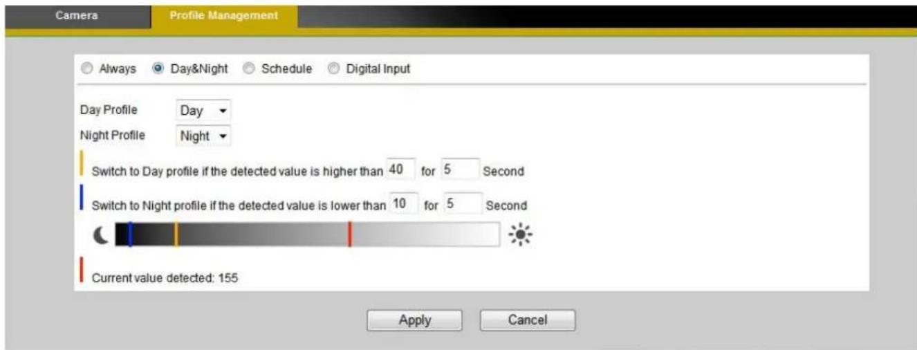
Day & Night (Only available with models with a light sensor)- Select Day & Night to schedule two profiles for day and night. Select profiles from the drop down menu for the Day and Night Profiles.

Schedule – Select Schedule to schedule specific time periods for different profiles.
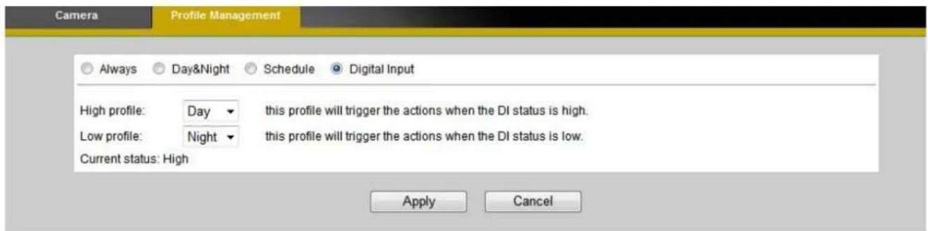
Digital Inputs (Only available with models with a DI terminal)- Select Digital Input to have the profile management controlled by an external sensor. Select profiles from the drop down menu. Profiles will change according to different trigger voltage levels.
Click Apply to apply settings or Cancel to cancel changes.
Video
The Network Camera offers two separate streams for different viewing options.

Stream 1 & Stream 2
Aspect Ratio – Select the width to height image aspect ratio.
Video Codec - The Network Camera offers three choices of video codec standards for real-time viewing: H.264, MPEG-4 and MJPEG.
Video Resolution - Select from the drop-down menu to choose the best resolution recording settings.
Frame Rate - Select the frame rate from drop-down menu. When H.264 or MJPEG is selected, the frame rate ranges from 1 to 30 fps. When MPEG-4 is selected, the frame rate ranges from 1 to 15 fps. Set a higher frame rate for smoother video quality.
Video quality and bit rate - Choose either “quality” or “bitrate” to control the video quality with video codec at H.264 or MPEG4. Only “quality” can be chosen when video codec at MJPEG is selected. Set the bitrate higher for a better video quality.
Transport-
RTP: The Real-time Transport Protocol (RTP) defines a standardized packet format for delivering audio and video over IP networks.
Brickcom
RTP with Quantization Table Header : Choose this option to explicitly include JPEG quantization table in the RTP stream [RFC 2435, section 3.1.8].
HTTP Transport: If MJPEG is used for Video Codec, HTTP Transport protocol must be enabled to remotely access the video stream.

NOTE - a higher bitrate will use higher network bandwidth. The video quality can be
set between Level 1 to Level 6, with Level 6 producing the best image quality.
HTTP Transport – If MJPEG is used for Video Codec, users can enable HTTP Transport protocol for video communication.

NOTE – HTTP Transport is for non-IE browser used only.
Click Apply to apply settings or Cancel to cancel changes.
Video Overlay

Timestamp
To display the date and time on the screen during live view, check "Enable" to enable the timestamp function and select the display position from the drop-down menu.
Text
To make a note about the camera, check "Enable" and select the display position from the drop-down menu. Enter a video description in the text box.
Click Apply to apply settings or Cancel to cancel changes.

NOTE - The video overlay will only takes effect in stream 1.
Brickcom
RTSP Server
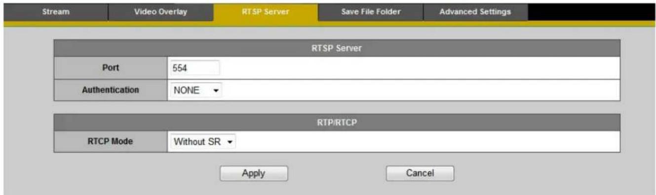
To utilize RTSP authentication, the user must first set a password for the camera. RTSP (Real-Time Streaming Protocol) controls the delivery of streaming media. By default the port number is set to 554.
Authentication - Depending on the network security requirements, the camera provides two types of security settings for streaming via RTSP protocol: NONE and DIGEST.
If DIGEST authentication is selected, user credentials are encrypted using MD5 algorithm, thus providing better protection against unauthorized access.
RTP/RTCP-
RTCP without SR - RTCP without SR (Sender Report) is the default option. Under this option, audio and video received from the IP camera are played immediately and independent of each other.
RTCP with SR - RTCP with SR option allows synchronization between video and audio on live viewing. Choose this option if audio and video become unsynchronized.
Click Apply to apply settings or Cancel to cancel changes.
Save File Folder

Brickcom
Recording folder path - The destination for saving the recording video files. Click Browse to specify the saving path.
Snapshot folder path - The destination for saving the snapshot files. Click Browse to specify the saving path and select the format from the drop-down menu.
Advanced Settings

Video usability information (VUI)- Enable this feature to insert extra information into the bit stream to enhance the use of the video for a wide variety of purposes.
Sequence Parameter Set (SPS) & Picture Parameter Set (PPS)-
Enable or disable SPS and PPS in the H.264 packet, Sequence parameter sets (SPS), which apply to a series of consecutive coded video pictures called a coded video sequence, and Picture parameter sets (PPS), which apply to the decoding of one or more individual pictures within a coded video sequence.
Click Apply to apply settings or Cancel to cancel changes.
Audio
The administrator can set up two separate streams for the camera for different viewing devices. The administrator can enable or disable the audio function on either stream. If audio enable is selected, select the Audio codec from the drop-down menu.
Brickcom

Advanced Settings

Camera Speaker – If the speaker is enabled, select the volume from the drop-down menu.
Echo Cancellation Enabled - Enable to avoid an echo.
Click Apply to apply settings or Cancel to cancel changes.
Multicast

Multicast sends a video stream to the multicast group address and allows multiple clients to acquire the stream at the same time by requesting a copy from the multicast group address.
Therefore, multicast can effectively save Internet bandwidth. The RTSP (Real-Time Streaming
Brickcom
Protocol) controls the delivery of streaming media.
Click "Enable" to enable Multicast stream 1 or Multicast stream 2. The default value for multicast address and port are 234.1.2.3 and 10000. Use different port number for different streams. It is recommended to use the default values.

NOTE - Using the IP address of the Network Camera enables access to the video.
Example: rtsp://192.168.1.1/channel1
Click Apply to apply settings or Cancel to cancel changes.
Privacy Mask Control
The Cube camera is equipped with a privacy feature which allows users to mask the camera's live view. A black screen will be displayed in place of the live view window. This application is particularly useful when the camera is being used for home surveillance. With the privacy button, the user can have privacy while they are going about their daily life.
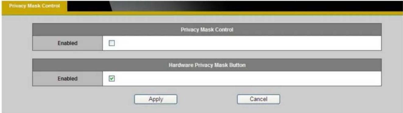
Privacy Mask Control – Enable the Privacy Mask control to remotely mask the camera's live view.
Hardware Privacy Mask Button – Click to enable the privacy mask button on the camera. If this feature is not enabled, the user will not be able to use the privacy mask button.
Click Apply to apply settings or Cancel to cancel changes.
Brickcom
Enabling De-Warp Function For Camera
From the camera search list, select the camera you wish to add. Enter the username and password for the camera (the default username is admin and the default password is admin), then click Add.

Drag the camera from the camera tree list to the live view window. The live view window will show the camera's image as below.
![Brickcom PC-NVR MD-580Ap-368-0230 2913/07/08 10:47:19 CB-300Ap-0133 [03] PB-040D-3cd9 PZ-040D-3cd9 [04] FB-300Ap-447a PB-300Ap-447a [05] GMD-100Ap-3933 GMD-200Ap-3933 [06] VPR-300Ap-415F VPR-300Ap-415F [07] HD-580Ap-360-02 HD-580Ap-360-02 Brightness Speaker Volume Camera List Setting PT3 Setting Liv…](/content/2026/06/1256506/images/40ab6dc1eb33d817d4b70339312e3e18e4ae7e8909801046fa9dde523e7206ab.jpg)
Brickcom
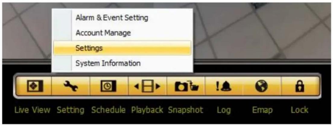
Click and choose Settings in the menu.
In Panorama Settings, click Enable and select the lens type of the selected camera.

Brickcom
- Immervision A8TRT:
For the 360P cameras (ex: MD-300Np-360P), please select Immervision A8TRT.

In the preview window, you can see an oval image with the black background. If you do not get the oval image, the de-warp function will not work properly.
Click OK to save and apply the panorama settings.
Brickcom
- FishEye:
For the 360C cameras (ex: MD-300Np-360C), please select FishEye.

In the preview window, you can see a circular image with the black background. If you do not get the circular image, the de-warp function will not work properly.
Click OK to save and apply the panorama settings.
Brickcom
- Immervision A0**V:
If you have a CS-mount ImmerVision Panomorph lens and want to use it with the camera (ex: CB-502Ap), please select Immervision A0**V.

In the preview window, you can see an oval image with the black background. If you do not get the oval image, the de-warp function will not work properly.
Click OK to save and apply the panorama settings.
Brickcom
![Brickcom PC-NVR Recommend Record Talk Sequence CSD Setting Image Ratio Unconnect Snapshot Disable Live View Image Effect Motion Detection Camera Info Image Post-processing Panorama Display Mode Camera Position Config Ceiling Ground wall [01] PB-130Ap-fb2a [02] OB-100Ap-b030 [03] PZ-040D-3cd5 [04] PB…](/content/2026/06/1256506/images/c061d23ff443d167e9817a338a3931ddb97898d18f128c89054850f568b144a2.jpg)
On the BRC64 PC-NVR, you can use the mouse or the software control panel to perform the PTZ (pan, tilt, zoom) operations. For the mouse-based PTZ control, the drag operation of the mouse changes the viewing direction, and the mouse wheel does the zoom-in and zoom-out of the image.
The result of the PTZ operation depends on where the camera is installed (on the ceiling, on the ground, or on the wall). For the BRC64 PC-NVR to know the actual position of the camera, please right click on the FishEye / Immervision A0**V / Immervision A8TRT camera image for the menu to pop up. Then select Image Effect → Panorama → Camera Position. Under Camera Position, 3 options are available: Ceiling, Ground, Wall.
| Ceiling Select this | option if the camera is installed on the ceiling facing the ground. |
| Ground Select this | option if the camera is installed on the ground facing the ceiling. |
| Wall Select this option if the camera is installed on the wall facing forward. | |
Brickcom
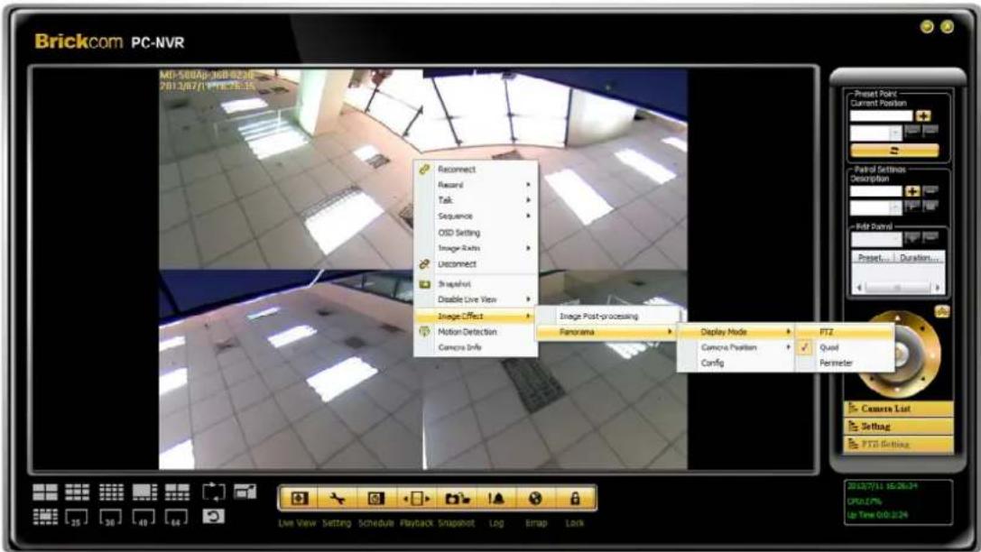
The BRC64 PC-NVR offers a few display modes for the FishEye / Immervision A0**V / Immervision A8TRT cameras, such as the normal PTZ-capable display, simultaneous quadruple PTZ-capable display, and the 180° perimeter display. To select the display mode, please right click on the FishEye / Immervision A0**V / Immervision A8TRT camera image for the menu to pop up. Then select Image Effect → Panorama → Display Mode. Under Display Mode, 3 options are available: PTZ, Quad, Perimeter.
| PTZ Select this option for the single display. The PTZ commands are applicable. |
| Quad Select this option for the 2x2 quadruple display. The PTZ commands are applicable to each of the displays, just like controlling 4 different cameras. |
| Perimeter Select this option for the 180° horizontal panoramic image. |
Brickcom
![[01] FB-130Np-fb2a FB-130Np-fb2a [02] OB-100Ap-b030 OB-100Ap-b030 [03] PZ-040D-3cd9 PZ-040D-3cd9 [04] FB-300Ap-447a FB-300Ap-447a [05] GMD-100Ap-3933 GMD-100Ap-3933 [06] WFB-300Ap-435f WFB-300Ap-435f [07] MD-500Ap-360-0230 MD-500Ap-360-0230 2 3 Camera List Setting PTZ Setting 1](/content/2026/06/1256506/images/5c02e83e04d3033d6833770c6cde832c647668936be1c27c88aee80764372ee2.jpg)
PTZ Control Panel:
Click the PTZ Setting button (marked by 1 on the picture) on the control panel to show the PTZ control section (marked by 2 on the picture). The PTZ control section consists of 8 directions and the Home button at the center.
- Click the direction buttons to change the viewing direction on the image.
- Click the Home button at the center of the PTZ control section to revert to the default viewing direction and zoom level.

After clicking the Setting button, the Zoom in and Zoom out buttons will show up.
Brickcom
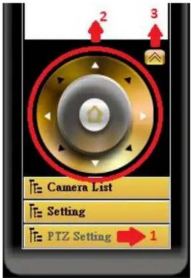
On the PTZ control section, click the arrow (marked by 3 on the picture) for the Preset Point and Patrol section to come up.
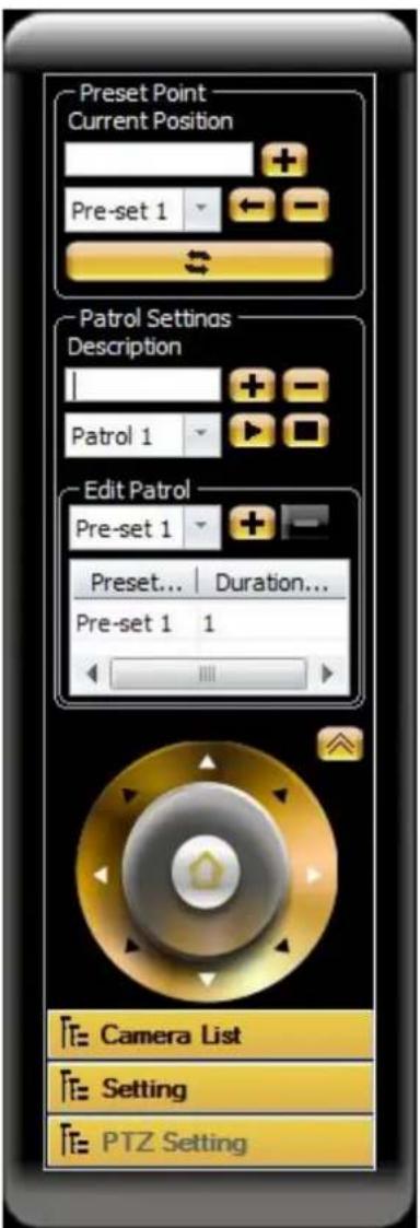
To set up the pre-set point(s):
- Determine the desired viewing direction and zoom level using the PTZ commands.
-
Enter the name into the Current Position field (ex. Pre-set 1),
then click to create a new pre-set point. Click to delete an existing pre-set point. -
On the drop-down list below the Current Position field, the user can view all the configured pre-set points. When the user selects a pre-set on the drop-down list and clicks the image corresponding to the preset will be Immediately displayed.
To set up the patrol rule(s):
- Enter the name into the Description field, then click

create a new patrol rule. Click to delete an existing rule.
- On the drop-down list below the Description field, the user can view all the configured patrol rules. When the user selects a patrol rule on the drop-down list and clicks ▶ the BRC64 PC-NVR will run this rule endlessly. Click ▶ stop the rule.
Brickcom
- When a patrol rule is selected, in the Edit Patrol section the user can see which pre-set points are included and put in order for the patrol rule. The user can select the desired pre-set point(s) on the drop-down list in the Edit Patrol section, then click + to add a pre-set point to the patrol rule, or click to delete a pre-set point from the patrol rule. The user can double-click the Duration field of each pre-set point to set the period of stay for the pre-set point.
Brickcom
Network
IP Settings
This section explains how to configure a wired network connection for the camera. There are several ways to setup the camera over the Internet: (1) obtain an available dynamic IP address assigned by a DHCP server, (2) use a static IP, or use PPPoE (Point-to-point over Ethernet). Select the desire setup mode from the IP settings drop-down menu.

- DHCP –If this option is selected, the camera will automatically obtain an available dynamic IP address from the DHCP server each time it connects to the LAN.

- Static IP - Select this option to manually assign a static IP address to the camera. Enter the static IP address, Subnet mask, Default Gateway, Primary and Secondary DNS provided by the ISP.
Brickcom

-
PPPoE (Point-to-point over Ethernet): Use this mode if connecting to the Internet through a DSL Line. NOTE - To utilize this feature, it requires an account provided by an Internet Service Provider. Enter the user name and password provided by the ISP. Click Apply to apply settings or Cancel to cancel changes.
-
3G(*) – Use this option if using a 3G SIM card to transmit video/audio surveillance over a 3G network
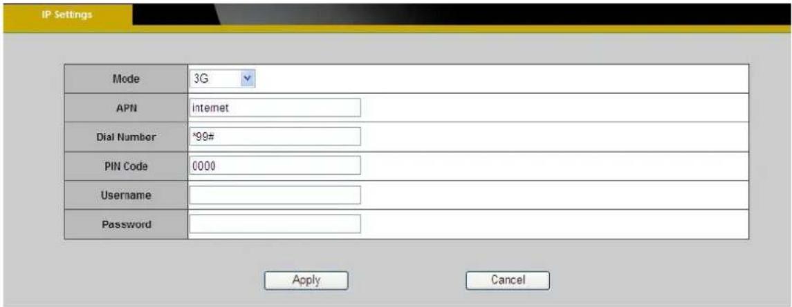

NOTE - This function is only available for GOB models.
a. Enter the APN (Access Point Number), Dial Number, PIN Code, User Name and Password provided by the ISP.
b. Click Apply to apply the settings. The message below will be displayed if the 3G settings were successfully applied.

c. Before disconnected the wired connection with the network camera, obtain the IP Address by opening EasyConfig. The 3G connection IP Address will be displayed in the IP Address column.
Brickcom

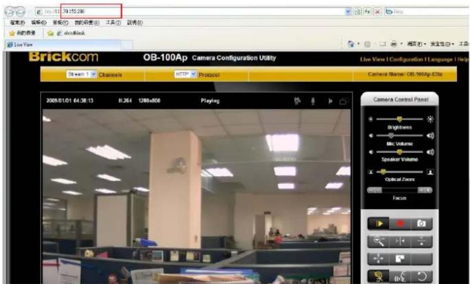
d. The network camera can now be accessed over a 3G network. To access the video feed through the internet, open a web browser and enter the network camera's IP address. A dialog window will pop up requesting a username and password. As stated on the previous page, the default username and password for the Administrator account are
"admin/admin".
UPnP
Universal Plug and Play (UPnP) simplifies the process of adding a camera to a local area network. Once connected to a LAN, the camera will automatically appear on the intranet. Click “Enable” to enable this function and enter an UPnP name which the camera will appear under on the intranet.
Brickcom

Click Apply to apply settings or Cancel to cancel changes.
DDNS (dynamic domain name service)
DDNS links a domain name to an IP address, allowing users to easily access their camera even with a changing IP address. Brickcom network cameras are compatible with three DDNS service providers (1) DynDNS, (2) TZO, and (3) No-IP. ⚠️NOTE - Before utilizing this function; please apply for a dynamic domain account from a DDNS provider.

DynDNS – Enable the DynDNS to allow the camera to have a fixed host and domain name. Refer to the DynDNS website (www.dyndns.com) to apply for a dynamic domain account. When an account has been created, enter the username, password and hostname.
Click Apply to apply settings or Cancel to cancel changes.
TZO

TZO is a DDNS provider which allows users to create a dynamic DNS. Refer to the TZO website (http://www.tzo.com/) to apply for a dynamic domain account. When an account has been created, enter the e-mail address, password and domain name.
Click Apply to apply settings or Cancel to cancel changes.
Brickcom
No-IP
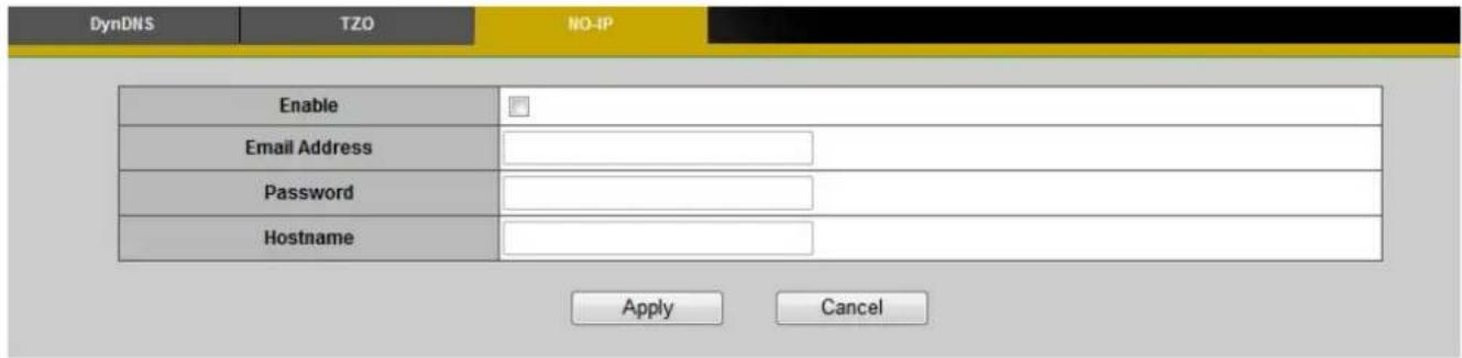
No-IP is a DDNS provider which offers DNS services, email, network monitoring and SSL certificates. Email services include POP3 email, outbound SMTP email, backup mail services and mail reflection and filtering. Refer to the No-IP website (www.no-ip.com) to apply for a dynamic domain account. When an account has been created, enter the e-mail address, password and domain name.
Click Apply to apply settings or Cancel to cancel changes.
EasyLink™
EasyLink™ is a unique Brickcom function which allows users to assign a unique EasyLink name to their network camera's IP address. There is no need to configure the router to open up ports or remember hard-to-memorize IP addresses. When this function is enabled, users can log onto [uniqueEasyLinkname].mybrickcom.com to view the camera's web GUI and live view.
- Check the box to enable EasyLink TM .
- If Auto mode is selected, the following page will be displayed. NOTE - This mode is recommended.
- Enter a unique EasyLink name whose length must be between 5-32 characters. Verify that the EasyLink name is available.

Brickcom
- If Manual mode is selected, the following page will be displayed.
a. Manually enter the Public IP Address, HTTP port and RTSP port or leave the default values.

Click Apply to apply settings or Cancel to cancel changes.

NOTE - The EasyLink function will not work if the following conditions occur:
- The camera cannot be located behind a double NAT network.
- The camera's IP address cannot be assigned to specific port numbers using the router's port forwarding.
- EasyLink uses UPnP to exchange port information with the router. The camera must connect to the internet through a router which supports UPnP.
Brickcom
Wireless
These settings control how a Network Camera interacts with a wireless network. Users can identify the wireless network and enable wireless encryption.

NOTE – This function is only available for WCB models.
Basic Settings

Network Name (SSID) - The Service Set Identifier (SSID) is the network name used to identify the wireless signal emitted from a wireless camera. It is case-sensitive and can be up to 32 characters long.
Wireless devices have a default SSID set by the factory. Brickcom wireless products use Brickcom as the default name. It is recommended for users to rename their SSID to something unique in order to distinguish their wireless device from surrounding wireless networks.

NOTE - Be careful when including personal information when naming the SSID as it is able by anyone browsing for wireless networks.
Brickcom
Security - Encryption protects data transmitted over a wireless network. Wi-Fi Protected Access (WPA-Personal/WPA2-personal) and Wired Equivalent Privacy (WEP) offer different levels of security for wireless communication. A network encrypted with WPA-Personal/WPA2-personal is more secure than a network encrypted with WEP because WPA-Personal/WPA2-personal uses dynamic key encryption. To protect the information as it passes through the airwaves, it is recommended to enable the highest level of encryption supported by the network equipment.
Site Survey – Survey the local area for available wireless networks. The user should select their Local Area Network (LAN) from the Site Survey List.
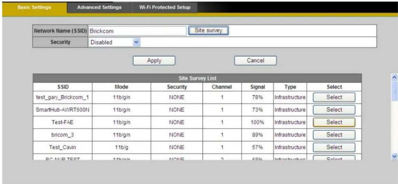
Brickcom
WEP- Wired Equivalent Privacy (WEP) is a basic encryption method which transmits network broadcast messages using radio signals. It is not as secure as WPA.

Tx Key - Select a key from the drop-down menu.
WEP Encryption - Select a level of WEP encryption: 64 bits 10 hex digits or 128 bits 26 hex digits. The default is 64 bits 10 hex digits.
Key 1-4 - Enter the WEP key(s) manually.
Authentication - The default is set to Open System, which allows either Shared Key or Auto authentication to be used. With Shared Key authentication, the sender and recipient use a WEP key for authentication. With Auto authentication, the sender and the recipient do not use a WEP key for authentication.
Click Apply to apply settings or Cancel to cancel changes.
WPA-Personal - WiFi Protected Access (WPA)-Personal

Encryption - Supports two encryption methods with dynamic encryption keys: Temporal Key Integrity Protocol (TKIP) and Advanced Encryption Standard (AES). Select the algorithm type from the drop down menu: TKIP or AES. The default is TKIP.
Shared Key - Enter the key shared between the Router and the server keys. Enter a password of 8-63 characters.
Click Apply to apply settings or Cancel to cancel changes.
WPA2-Persona I - WiFi Protected Access (WPA2-Personal)

Encryption - WPA2 supports AES encryption method with dynamic encryption keys.
Shared Key - Enter the key shared between the Router and the server keys. Enter a password of 8-63 characters.

NOTE - If using WPA or WPA2, each device in the wireless network must use the same
WPA or WPA2 method and shared key or else the network will not function properly.
Advanced Settings

Network Mode - From the drop-down menu, select the wireless standards running on the network.
- If there are Wireless-B, Wireless-G and Wireless-N (2.4GHz) devices on the network, use the default setting, BGN-Mixed.
- If there are Wireless-B and Wireless-G devices on the network, select BG-Mixed.
- If there are only Wireless-B devices on the network, select Wireless-B Only.
- If there are only Wireless-G devices on the network, select Wireless-G Only.
- If there are only Wireless-N (2.4GHz) devices on the network, select Wireless-N Only.
•(*)If there are Wireless-A and Wireless-N devices on the network, select AN-Mixed. - (*)If there are Wireless-A, Wireless-B, Wireless-G and Wireless-N (2.4GHz) devices on the network, use the default setting, ABGN-Mixed.
•(*)If there are only Wireless-A devices on the network, select Wireless-A Only.
Radio Band - The settings are available for the Auto-20/40MHz channel and Standard-20 MHz channel.
Enable WMM (802.1e QoS) - WMM is a wireless Quality of Service feature that improves quality for audio, video, and voice applications by prioritizing wireless traffic. To use this feature, the wireless client devices on the network must support Wireless WMM. The default setting is
Enabled. To disable this feature, select Disable.
Click Apply to apply settings or Cancel to cancel changes
Wi-Fi Protected Setup
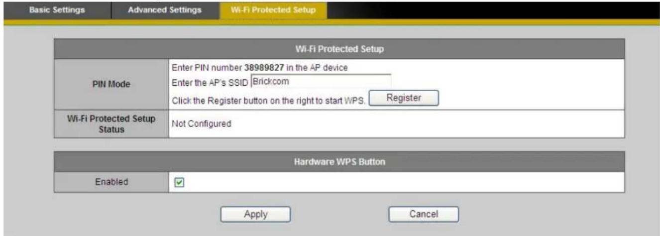
Use this method if the client device has a Wi-Fi Protected Setup PIN number.
- Enter the network name from the device in the field.
- Click
to start WPS. - Click "Enable" to enable the WPS Button. If this feature is not enabled, the user will not be able to use the WPS button
Click Apply to apply settings or Cancel to cancel changes.
HTTP/HTTPS
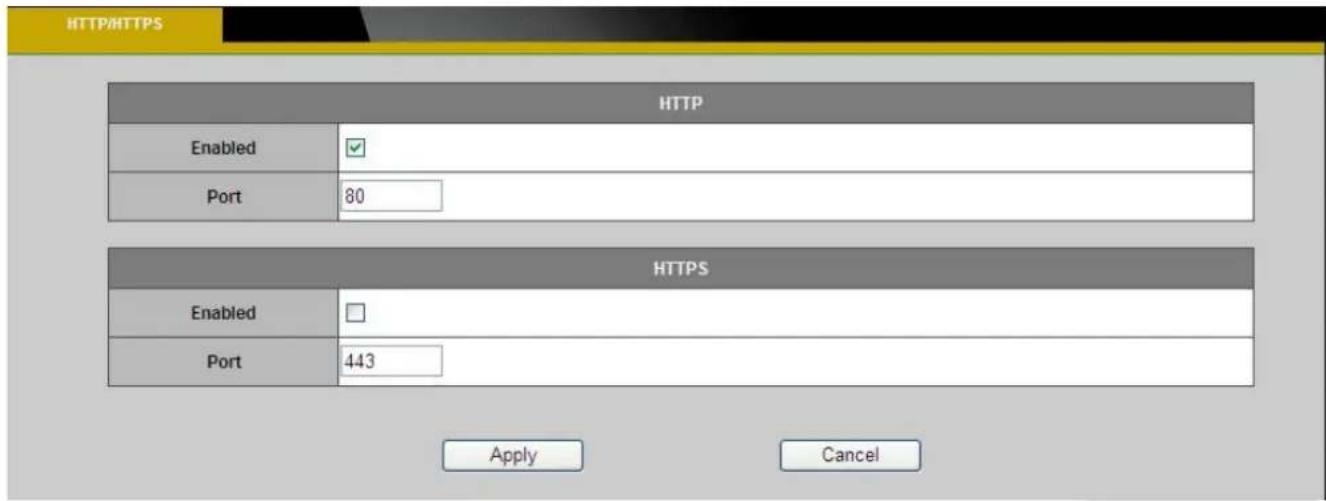
HTTP – (HyperText Transfer Protocol) - This protocol allows for TCP protocol quality without having to open specific ports for streaming. Users inside a firewall can utilize this protocol to allow streaming data through.
HTTPS - (Hypertext Transfer Protocol over SSL) - This protocol allows authentication and encrypted communication over SSL (Secure Socket Layer). It helps protect streaming data transmission over the Internet on a higher security level than HTTP.
Click "Enable" to enable and Apply to apply settings or Cancel to cancel changes.
Brickcom
To enable HTTPS, users have to create and install a certificate.
- Click "Continue to this website" to install.

There is a problem with this website's security certificate.
The security certificate presented by this website was issued for a different website's address.
Security certificate problems may indicate an attempt to fool you or intercept any data you send to the server.
We recommend that you close this webpage and do not continue to this website.
√ Click here to close this webpage.
Continue to this website (not recommended).
More information
- Enter the User name and Password of the camera.
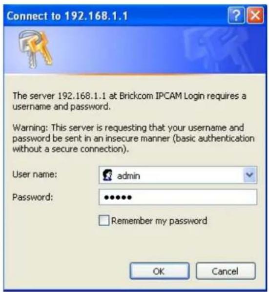
Brickcom
- Click "Certificate Error" on the top right corner of the window to view the certificate.

- Click "Install Certificate" and follow the steps to finish the installation.

Brickcom
Event
Event Settings
When an event (such as unauthorized movement) occurs, the camera can be scheduled to perform certain actions. An Event Type is a set of parameters that defines these actions. This section describes how to configure the camera to perform certain actions when events occur.

Click

How to Set Up an Event Schedule
Event Schedule describes how and when the camera performs certain actions.
- Check "Enable" and enter a descriptive name for the event schedule.
Brickcom
- Set Event Schedule to define when the event is activated by selecting from Always (24 hours), Schedule or Recurrence pattern.
a. If Schedule is selected from the Event Schedule, the following page will be displayed:
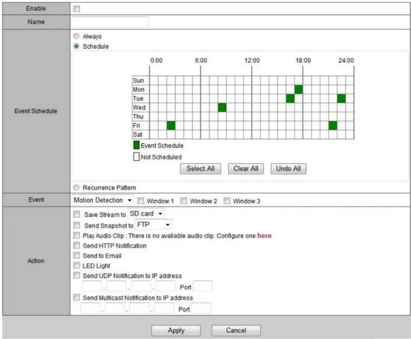
A Scheduled Event can be programmed for certain times and day. Click individual boxes to schedule specific times for the camera to detect events.
b. If Recurrence Pattern is selected, the following page will be displayed.
Event Settings
| Event List | |||
| Enabled | Name | Event Type | Action |
| 12345 | Motion Detection | Send to Email | |
| abcde | PIR | Take Snapshot | |
| asdf | Audio | LED Light | |

| Enabled | |
| Name | asdf |
| Event Schedule | AlwaysScheduleRecurrence PatternSunMonTueWedThuFriSatStart00:07Duration10Minutes |
| Event | Audio Detection |
| Action | Save Stream to SD cardSend Snapshot to FTPPlay Audio Clip : There is no available audio clip. Configure one hereSend HTTP NotificationSend to EmailLED LightSend UDP Notification to IP addressPortSend Multicast Notification to IP addressPort |

i. An event schedule can be programmed to recur at different times according to the user's needs. Select the days for the event schedule to occur. Select a start time and specify the duration.
- Define what will trigger an event to occur by selecting an option from the Event drop-down list.
- Select the Actions that will occur when the event is triggered.
Brickcom
a. When
| Enable | |
| Name | |
| Event Schedule | AlwaysScheduleRecurrence Pattern |
| Event | Motion Detection ▼ Window 1 □ Window 2 □ Window 3 |
| Action | Save Stream to FTP ▼Send Snapshot to FTP ▼Play Audio Clip : There is no available audio clip. Configure one hereSend HTTP Notification✓ Send to EmailLED LightSend UDP Notification to IP address. . . . . . PortSend Multicast Notification to IP address. . . . . . Port |
| SenderTOCCSender's NameSubject |
i. Sender - Enter the email address of the sender.
ii. Recipient - Enter the email address of the recipient. To enter multiple recipients, separate each using a comma.
iii. Sender's Name – Enter the sender's name that will appear in the recipient's inbox.
iv. Subject - Enter the title of the email.
- When complete, click Apply to save new event or Cancel to delete the event. The new event will appear on the event list.
- To edit an event setting; select the event from the list. To remove an event setting from the list, select an event name from the list and then click
. Click to add more events.

NOTE - Refer to the Audio Clip section for more details about the "Play Audio Clip" action.
Brickcom
Motion Detection
Motion can be detected by measuring changes in the speed or vector of an object or objects in the monitored area. This section explains how to configure the Network Camera to enable motion detection.
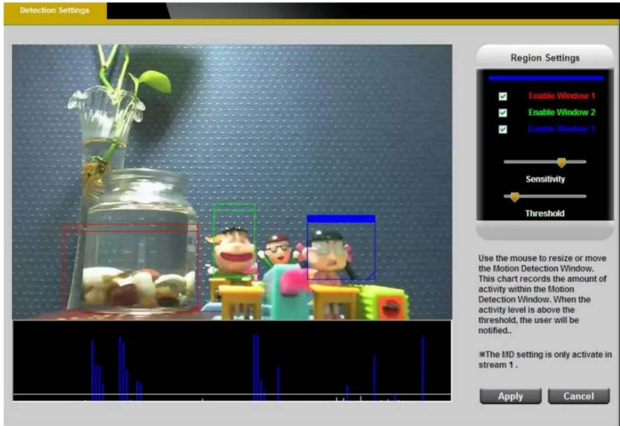
Detection Setting – Use this setting to enable and define the motion detection windows. The user can defined up to three areas on the live view window for motion detection.
- Select
, , or to adjust the motion detection window. - Check the box to enable the window.
- Use the mouse to resize or move the motion detection window.
- Adjust the "Sensitivity" level. Lower sensitivity levels will result in more activity needed to trigger an event.
- Adjust the "Threshold" to change the threshold level. The higher the threshold, the larger objects need to be to trigger an event.
- The chart below the Live View window indicates the activity level of the Motion Detection window. When motion is detected by the camera and exceeds the defined threshold, a red bar will appear. Users can use this feature as a trigger source to send photos or videos to a remote server via email or FTP.
Click Apply to apply settings or Cancel to cancel changes.
Brickcom
PIR(*)

The PIR (Passive InfraRed) sensor measures infrared light radiating from objects in its field of view. This can be used to detect a moving object, such as a person, in dimly lit areas.
Sensitivity – Adjust the sensitivity of the PIR Sensor from the drop down menu. The sensitivity can be set from 10 - 100%; with the default sensitivity set at 50%. Higher sensitivity levels will increase the range of the PIR Sensor. When the sensitivity level is set to 100%, the PIR sensor will be able to detect moving objects within six meters.
Audio Detection

Users can schedule an event to be triggered if there is a change in the sound level of a monitored area. Audio detection can be used to measure change in the ambient voice. Select the sensitivity from the drop-down menu.
Sensitivity - is used to adjust the sensitivity of the sound level from 10 - 100%. The default sensitivity is 50%.

60%
Display the current sound level.
Click Apply to apply settings or Cancel to cancel changes.
Brickcom
Notifications
Use the tools in this section to specify what type of notification will be sent when an event occurs. The camera can send buffered images to an FTP server, Samba, Email, or HTTP.
FTP Settings
File Transfer Protocol (FTP) is used as an application component to automatically transfer files for program internal functions. Select "Primary FTP Server" from the Server Selection drop down menu to send media files to a FTP server when an event is triggered. Enter the FTP IP address or hostname. By default, the FTP port server is set to 21. Enter the account name, password and FTP Path to configure the settings.
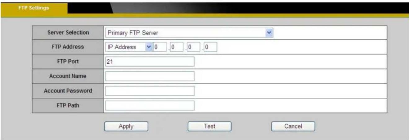
Click Apply to apply settings or Cancel to cancel changes.
Brickcom
E-mail Settings
Select "Primary Email Server" option from the Server Selection drop down menu to send media files to an email server when an event is triggered.
SMTP Server - Enter the server host name of the email server.
SMTP Port - Enter the port number of the email server; by default, the SMTP port is set to 25.
Authentication - Select the authentication type from the drop-down menu.
Email Account - Enter the user name of the email account if necessary.
Email Password - Enter the password of the email account if necessary.

Click Apply to apply settings or Cancel to cancel changes.
Samba Settings
Select this option to send the media files via a network neighborhood when an event is triggered.
Server Address - Enter the IP address of the Samba server.
User Name - Enter the user name of the Samba server.
Password - Enter the password of the Samba server.
Work Group - Enter the workgroup of the Samba server.
Shared Folder - Enter the share folder of the Samba server.

Click Apply to apply settings or Cancel to cancel changes.
Brickcom
HTTP Settings
Select this option to send the media files via an HTTP notification when an event is triggered.

URL –Specify the URL to send HTTP requests. The URL is normally written as:
http://ip_address/ notification.cgi?parameter
ip_address – type the IP address or host name of the HTTP host.
Parameter – type the notification parameter if necessary.
Example
URL - http://192.168.1.1/xxxx.cgi
Message - name1=value1&name2=vlaue2
Result - http://192.168.1.1/xxxx.cgi? name1=value1&name2=vlaue2
Ex:
https://192.168.1.1/notification.cgi?event=MD&camera=FB-100A
Message - Enter the message notification that will be sent when an event is triggered.
Enter the user name and password if necessary.
Click Apply to apply settings or Cancel to cancel changes.
Brickcom
Video Clip

This function is used to determine when video clips will be recorded and stored after an event is triggered.
Pre-alarm buffer - Images can be stored internally on the server from the time immediately preceding the trigger. Enter the desired length of time.
Post-alarm buffer - Images can be stored internally on the server from the time immediately following the trigger. Enter the desired length of time.
Maximum buffer size –Specify the maximum file size allowed.
Click Apply to apply settings or Cancel to cancel changes.
Brickcom
Audio Clip(*)
Audio Recording – Audio clips can be recording and played when an event occurs.

Click Browse to import a file from a local hard drive or network disk. Select the file and click
Import. ⚠️ NOTE – The camera can only play audio clips which are saved as .wav files with G.711 u-law encoding in 8000 Hz sampling rate.
To record a new clip using the camera's microphone:
- File Name-Enter a file name.
- Duration - Enter the number of seconds to record.
- Click Record to record the new audio clip.
- The new audio clip will appear on the audio clip list.
- Select an audio clip file from the Audio Clip List.
a. Play- Select to hear the audio clip
b. Stop- Select to stop playing the audio clip.
c. Delete- Select to delete an audio clip.
d. Export- Select to export the audio clip to a local hard drive or network disk.
Brickcom
LED Light(*)

Mode – Select “Keep active during event” or “Keep active for” a specific amount of time when an event is triggered.
LED Control - The LED on the front of the camera can be set to flash at a configurable interval when an event is triggered. From the Activate drop down menu, select a percentage which the LED will brighten to. When the LED reaches the selected percentage, it can be configured to fade to off or turn off. Select the option from the Inactive menu.
Click Apply to apply settings or Cancel to cancel changes.
Brickcom
System
System Log
Log - Set up the camera to record a system log when an event is triggered.
![LOG_WARNING-Wireless :Wireless connection for SSID [Brickcom]' is down, Thu Jan 1 00:00:12 2009 LOG_NOTICE-WebServer :User [admin]' logged in to [web server], Thu Jan 1 00:02:35 2009 LOG_NOTICE-WebServer :User [admin]' logged in to [web server], Thu Jan 1 00:02:52 2009 LOG_INFO-stream :Channel [1] s…](/content/2026/06/1256506/images/15036ca5ed32b56e8a3d32fda39538441e7ddf3c4caa7545e13b02d1650cd56d.jpg)
This page displays the system's log in chronological order. The system log is stored in the camera's buffer area and will be overwritten when the buffer area is full.
Click Retrieve to retrieve the log or click Save to file to save the system log.
Brickcom
Remote Logging

The user can configure the camera to send the system log file to a remote server as a log backup.
Click to enable remote log and enter the IP address of the remote server.
Enter the port number of the remote server.
Click Apply to apply settings or Cancel to cancel changes.
Date and Time
Manual – Manually enter the date and time.
Clone from PC – The camera will sync with the time, date and time zone of the computer used to modify the camera settings. Check “Clone” to utilize this option. The read-only date and time of the PC will be displayed.
NTP – (Network Time Protocol) - NTP is a protocol for synchronizing the clocks of a computer system. Select to update the time with a NTP server on an hourly, daily, weekly, or monthly basis.
Time Zone – Select the local time zone from drop-down menu.
NTP Server 1 and Server 2 - Enter the address of the NTP server
Daylight Saving - Enable this option to automatically update for Daylight Savings Time.

Click Apply to apply settings or Cancel to cancel changes.
Brickcom
Device Information
System Information – Displays the complete system information of the camera.
| LAN MAC Address | 00:26:82:B6:3C:7B |
| Firmware Version | v3.1.0.2 |
| Product Name | CB-100Ap |
| Hardware Version | V2 |
| Company Name | Brickcom Corporation |
| UPnP Name | CB-100Ap-3c7b |
Network Settings – Displays the complete network settings information of the camera.
| IP Information | |
| IP Setting Type | DHCP |
| IP Address | 192.168.1.21 |
| Subnet Mask | 255.255.255.0 |
| Default Gateway | 192.168.1.2 |
| Primary DNS | 192.168.1.2 |
| Secondary DNS | 192.168.1.2 |
| Network Services | |
| UPnP | Enabled |
| DynDNS | Disabled |
| TZO | Disabled |
| NO-IP | Disabled |
Video/Audio Settings – Displays the complete video/audio settings information of the camera.
| Stream 1 | |
| Video Codec | H.264 |
| Video Resolution | 1280x800 |
| Video Frame Rate | 25 fps |
| Video Bitrate | 4000 Kbps |
| Audio Codec | N/A |
| Multicast IP | N/A |
| Stream 2 | |
| Video Codec | MJPEG |
| Video Resolution | 1280x800 |
| Video Frame Rate | 25 fps |
| Video Quality | 3 |
| Audio Codec | N/A |
| Multicast IP | N/A |
Brickcom
Wireless - Displays the complete wireless information of the camera.
| System Information | Network Settings | Video/Audio Settings | Wireless | |
| Wireless MAC Address | 00:26:82:1B:DB:92 | |||
| Radio Band | Auto-20/40MHz Channel | |||
| Network Mode | BGN-Mixed | |||
| Security | Disabled | |||
| Network Name (SSID) | Brickcom_MARS | |||
| Wireless Channel | 6 | |||
| Wireless Signal Strength | 85% | |||
| Status | Connected | |||
Client Information- Displays the RTSP Client .You will see a list of RTSP clients with the following information: IP Address and channel.

Brickcom
Storage Management (*)
Storage Management is used to view all the recorded files on the Micro-SD/SDHC card.
| Local Storage Information | |
| Item | SD Card |
| Total Capacity | 7.41GB |
| Used Space | 2.27GB |
| Available Space | 5.14GB |
| Memory Card Management | Reload Remove Format |
| Storage Management | |
Click Reload to refresh the list of recorded files.
Click Remove to safely remove the Micro-SD/SDHC memory card.
Click Format to format the Micro-SD/SDHC memory card.
Left click on the folder to list the recorded files. The user can either play the snapshot of the recorded files by moving the mouse pointer over the file or double click on a file to play it.
Right click on the folder to download, play or delete the recorded files.

NOTE – The user may need to install QuickTime multimedia framework to play the video clips.
Advanced Settings

Automatic Recycle (*) – Enable to automatically overwrite older files when the available space remaining on the Micro-SD/SDHC card is less than 100MB. If the Automatic Recycle function is disabled, there must be at least 50MB hard drive space available for the camera to be able to record video files.
Offline Record – Enable to keep recording if the Network Camera is offline.
File Encryption – Enable the File Encryption to encrypt recorded video files. Files are encrypted using OPENSSL.
To unlock the encrypted file, please download and install the OPENSSL toolkit from the OPENSSL Web site.
http://gnuwin32.sourceforge.net/packages/openssl.htm
Use the following command to encrypted file:
openssl enc -ciphername [-in filename] [-out filename] [-pass arg] [-e] [-d] [-a/-base64] [-A] [-k password] [-kfile filename] [-K key] [-iv IV] [-S salt] [-salt] [-nosalt] [-z] [-md] [-p] [-P] [-bufsize number] [-nopad] [-debug] [-none] [-engine id]
For example: openssl enc -d -aes128 -in encryptfile -out decryptfile -k password
Click Apply to apply settings or Cancel to cancel changes.
LED Indicators
The LED on the front of the camera can be configured to remain unlit. Check "OFF" to enable
Brickcom
this function.

Click Apply to apply settings or Cancel to cancel changes.
Brickcom
Maintenance
User Management
This section explains how to enable password protection and create multiple accounts.

The administrator account name is "admin", which is permanent and cannot be deleted. Click Add to create an account.

Enter the new user's name, password and confirm password. Administrators can add up to 10 user accounts.
Select the privilege level for the new user account from the drop-down list. Privilege levels can be assigned as:
Brickcom
◆ Administrator - user has access to view and change the Configuration page. Users with administrator privilege can change other user's access rights and delete user accounts. Click Delete or Update to delete or modify a user's account.
◆ Viewer - user can only access the main page for live viewing.
◆ Remote Viewer - user can only access the main page for live viewing using TCP protocol.
Language

Select the desired language from the radio button.
Click Apply to apply settings or Cancel to cancel changes.
IP Filter
The IP Filter is used to filter the IP addresses which are able to access the network camera. Enable the IP Filter and select to allow or deny a range of IP addresses access to the server. Click Add to list to add the IP range to the IP filter list.

Click Apply to apply settings or Cancel to cancel changes.
Brickcom
Firmware Upgrade
This feature allows the user to upgrade the camera firmware. It will take a few minutes to complete the process.

NOTE - Do not power off the camera or camera during the upgrade.
Upgrade - Click Browse... and specify the firmware file. Click Upgrade. The camera will begin upgrading and will reboot automatically when the upgrade is finished.

Configuration
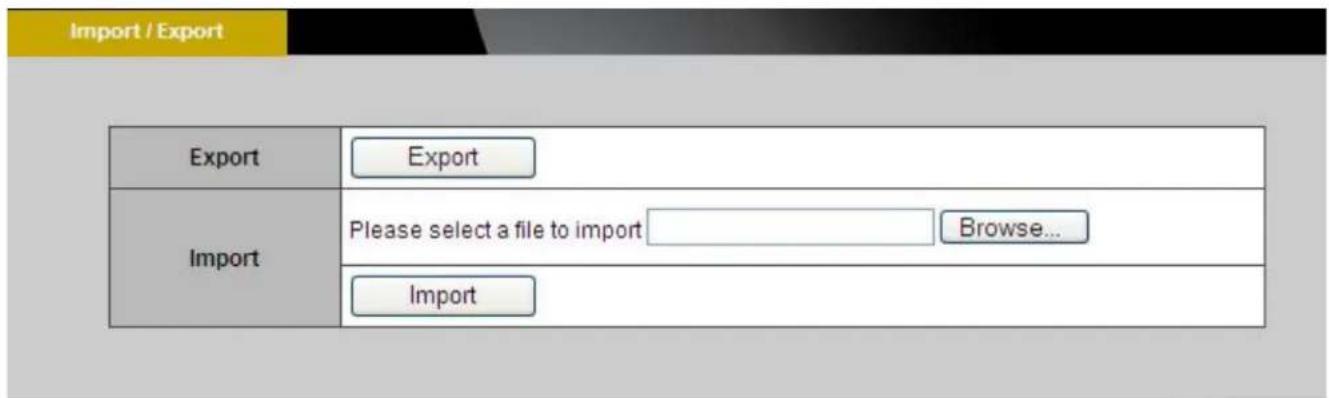
This feature allows the user to export/import the configuration files of the network camera.
Import/Export - Click export to pop up a dialog to indicate the location and file to export. Click browse to indicate the location and file of the camera configuration and click import to import the configuration file back into the network camera.
Brickcom
Reset to Default
This section is used to restore the camera to default factory settings. Check the boxes to preserve the IP, Wireless, Date and Time, EasyLink, or Language settings. Click Apply to restore the camera to default factory settings.

Reboot

This feature will reboot the camera. Click Apply to begin. A message will pop up asking "The device will reboot. Are you sure?" Click "OK" to continue. The camera will take about one minute to reboot.

The following message will show during the rebooting process.

When completed, the live video page will be displayed in the web browser.
- MEGAPIXEL CUBE NETWORK CAMERA
- CB-100A/CB-500A SERIES
- USER'S MANUAL
- QUALITY SERVICE GROUP
- TABLE OF CONTENTS
- BRICKCOM
- BEFORE YOU USE THIS PRODUCT
- FCC WARNING
- REGULATORY INFORMATION
- FEDERAL COMMUNICATION COMMISSION INTERFERENCE STATEMENT
- IMPORTANT NOTE
- FCC RADIATION EXPOSURE STATEMENT
- PACKAGE CONTENTS
- CUBE NETWORK CAMERA OVERVIEW
- SMALL OFFICE SURVEILLANCE
- RESIDENCE MONITOR
- ELDERLY AND CHILD CARE
- PET MONITOR
- DEVICE APPEARANCE DESCRIPTION
- HARDWARE RESET
- MICRO-SD/SDHC CARD CAPACITY
- INSTALLATION
- SYSTEM REQUIREMENTS
- CAMERA CONNECTION
- TERMINAL I/O CONNECTOR BLOCK CONNECTION
- BASIC CONNECTION
- SOFTWARE INSTALLATION
- IF CUSTOM SETUP IS SELECTED
- EASYCONFIG
- ACCESSING THE NETWORK CAMERA
- CHECK NETWORK SETTINGS
- ADD PASSWORD TO PREVENT UNAUTHORIZED ACCESS
- AUTHENTICATION
- INSTALLING THE PLUG-IN
- LIVE VIEW
- STREAM1/STREAM2 CHANNELS
- HTTP/TCP/UDP PROTOCOL
- NOTE
- CONFIGURATION
- CAMERA/VIDEO/AUDIO
- EXPOSURE CONTROL
- MIRROR AND FLIP
- DE-NOISE
- VIDEO
- STREAM 1 & STREAM 2
- TRANSPORT
- VIDEO OVERLAY
- TIMESTAMP
- TEXT
- RTP/RTCP
- SEQUENCE PARAMETER SET (SPS) & PICTURE PARAMETER SET (PPS)
- AUDIO
- ADVANCED SETTINGS
- MULTICAST
- PRIVACY MASK CONTROL
- ENABLING DE-WARP FUNCTION FOR CAMERA
- IMMERVISION A8TRT
- FISHEYE
- IMMERVISION A0**V
- NETWORK
- IP SETTINGS
- ADMIN/ADMIN
- UPNP
- TZO
- EASYLINK™
- WIRELESS
- EVENT
- EVENT SETTINGS
- HOW TO SET UP AN EVENT SCHEDULE
- MOTION DETECTION
- PIR(*)
- AUDIO DETECTION
- NOTIFICATIONS
- FTP SETTINGS
- E-MAIL SETTINGS
- SAMBA SETTINGS
- HTTP SETTINGS
- VIDEO CLIP
- AUDIO CLIP(*)
- LED LIGHT(*)
- SYSTEM
- SYSTEM LOG
- REMOTE LOGGING
- DATE AND TIME
- DEVICE INFORMATION
- STORAGE MANAGEMENT (*)
- LED INDICATORS
- MAINTENANCE
- USER MANAGEMENT
- IP FILTER
- FIRMWARE UPGRADE
- RESET TO DEFAULT
- REBOOT
Brand : Brickcom
Model : WCB-202AP
Category : Surveillance Camera