
M3113-R - Surveillance Camera AXIS - Free user manual and instructions
Find the device manual for free M3113-R AXIS in PDF.

| Product type | Fixed dome network camera |
| Brand | Axis |
| Model | M3113-R |
| Maximum resolution | 1 MP (1280 x 800) |
| Lens | Fixed focal length, 2.8 mm, F1.6 |
| Night vision | Yes, built-in IR LEDs (range 10 m) |
| Power supply | PoE (IEEE 802.3af), 5.5 W max |
| Dimensions (diameter x height) | 110 x 65 mm |
| Weight | 290 g |
| Protection rating | IP52 |
| Connectivity | Ethernet 10/100, PoE, I/O connector |
| Main functions | Motion detection, H.264 video, digital zoom, multiple streams |
| Storage | MicroSD (up to 64 GB), NAS, FTP server |
| Security | Password protection, HTTPS, IP filtering, IEEE 802.1X |
| Maintenance and cleaning | Dust with a soft dry cloth. Do not use abrasive cleaners. |
| Spare parts | No user-replaceable parts (except SD card) |
| Repairability | Not user-serviceable. Contact AXIS after-sales service. |
| General information | Manufacturer's warranty 3 years. Operating temperature: -10 to 50 °C. |
Frequently Asked Questions - M3113-R AXIS
User questions about M3113-R AXIS
0 question about this device. Answer the ones you know or ask your own.
Ask a new question about this device
Download the instructions for your Surveillance Camera in PDF format for free! Find your manual M3113-R - AXIS and take your electronic device back in hand. On this page are published all the documents necessary for the use of your device. M3113-R by AXIS.
USER MANUAL M3113-R AXIS
AXIS M31 Network Camera Series
AXIS M3113-R Network Camera
AXIS M3113-R M12 Network Camera
AXIS M3114-R Network Camera
AXIS M3114-R M12 Network Camera
About this Document
This document includes instructions for installing AXIS M3113-R, AXIS M3113-R M12, AXIS M3114-R and AXIS M3114-R M12 on your network. Previous experience of networking will be beneficial when installing the product.
Legal Considerations
Video and audio surveillance can be prohibited by laws that vary from country to country. Check the laws in your local region before using this product for surveillance purposes.
This product includes one (1) H.264 decoder license. To purchase further licenses, contact your reseller.
Electromagnetic Compatibility (EMC)
This equipment generates, uses and can radiate radio frequency energy and, if not installed and used in accordance with the instructions, may cause harmful interference to radio communications. However, there is no guarantee that interference will not occur in a particular installation.
If this equipment does cause harmful interference to radio or television reception, which can be determined by turning the equipment off and on, the user is encouraged to try to correct the interference by one or more of the following measures: Re-orient or relocate the receiving antenna. Increase the separation between the equipment and receiver. Connect the equipment to an outlet on a different circuit to the receiver. Consult your dealer or an experienced radio/TV technician for help. Shielded (STP) network cables must be used with this unit to ensure compliance with EMC standards.
USA – This equipment has been tested and found to comply with the limits for a Class B computing device pursuant to Subpart B of Part 15 of FCC rules, which are designed to provide reasonable protection against such interference when operated in a commercial environment. Operation of this equipment in a residential area is likely to cause interference, in which case the user at his/her own expense will be required to take whatever measures may be required to correct the interference.
Canada – This Class B digital apparatus complies with Canadian ICES-003.
Europe - C€ This digital equipment fulfills the requirements for radiated emission according to limit B of EN55022, and the requirements for immunity according to EN55024 residential and commercial industry.
Japan – This is a class B product based on the standard of the Voluntary Control Council for Interference from Information Technology Equipment (VCCI). If this is used near a radio or television receiver in a domestic environment, it may cause radio interference. Install and use the equipment according to the instruction manual.
Australia – This electronic device meets the requirements of the Radio communications (Electromagnetic Compatibility) Standard AS/NZS CISPR22.
Korea - Class B: As this equipment has obtained EMC registration for household use, it can be used in any area including residential areas.
Equipment Modifications
This equipment must be installed and used in strict accordance with the instructions given in the user documentation. This equipment contains no user-serviceable components. Unauthorized equipment changes or modifications will invalidate all applicable regulatory certifications and approvals.
Liability
Every care has been taken in the preparation of this document. Please inform your local Axis office of any inaccuracies or omissions. Axis Communications AB cannot be held responsible for any technical or typographical errors and reserves the right to make changes to the product and documentation without prior notice. Axis Communications AB makes no warranty of any kind with regard to the material contained within this document, including, but not limited to, the implied warranties of merchantability and fitness for a particular purpose. Axis Communications AB shall not be liable nor responsible for incidental or consequential damages in connection with the furnishing, performance or use of this material.
RoHS
This product complies with both the European RoHS directive, 2002/95/EC, and the Chinese RoHS regulations, ACPEIP.

WEEE Directive
The European Union has enacted a Directive 2002/96/EC on Waste Electrical and Electronic Equipment (WEEE Directive). This directive is applicable in the European Union member states.
The WEEE marking on this product (see right) or its documentation indicates that the product must not be disposed of together with household waste. To prevent possible harm to human health and/or the environment, the product must be disposed of in an approved and environmentally safe recycling process. For further information on how to dispose of this product correctly, contact the product supplier, or the local authority responsible for waste disposal in your area.
Business users should contact the product supplier for information on how to dispose of this product correctly. This product should not be mixed with other commercial waste. For more information, visit www.axis.com/techsup/commercial waste
Support
Should you require any technical assistance, please contact your Axis reseller. If your questions cannot be answered immediately, your reseller will forward your queries through the appropriate channels to ensure a rapid response. If you are connected to the Internet, you can:
- download user documentation and firmware updates
- find answers to resolved problems in the FAQ database; search by product, category, or phrases
- report problems to Axis support by logging in to your private support area.
AXIS M31 Series Installation Guide
This installation guide provides instructions for installing the following network cameras:
For all other aspects of using the product, please see the user's manual, available in the CD included with this package, or from www.axis.com/techsup
Installation steps
- Check the package contents against the list below.
- See Hardware overview. See page 4.
- Install the hardware. See page 6.
- Assign an IP address. See page 8.
- Set the password. See page 11.
- Adjust the focus. See page 12.
- Complete the installation. See page 12.
Important!
This product must be used in compliance with local laws and regulations.
Package contents
| Item Models/variants/notes | |
| Network camera AXIS | M3113-R, AXIS M3113-R M12, AXIS M3114-RAXIS M3114-R M12 |
| Lens toolDrill templateAllen key | |
| Optional accessories Adaptor for flat surface with 4 screwsAdaptor for curved surface | |
| CD | AXIS Network Video Product CD, including product documentation, installation tools and other software |
| Printed Materials AXIS | M31 Network Camera Series Installation Guide (this document)Axis Warranty Document |
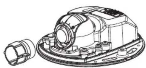
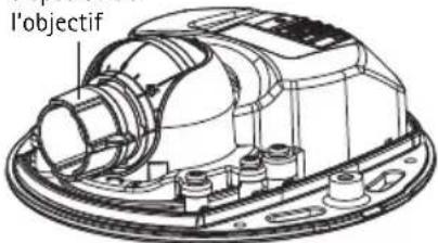
Hardware overview
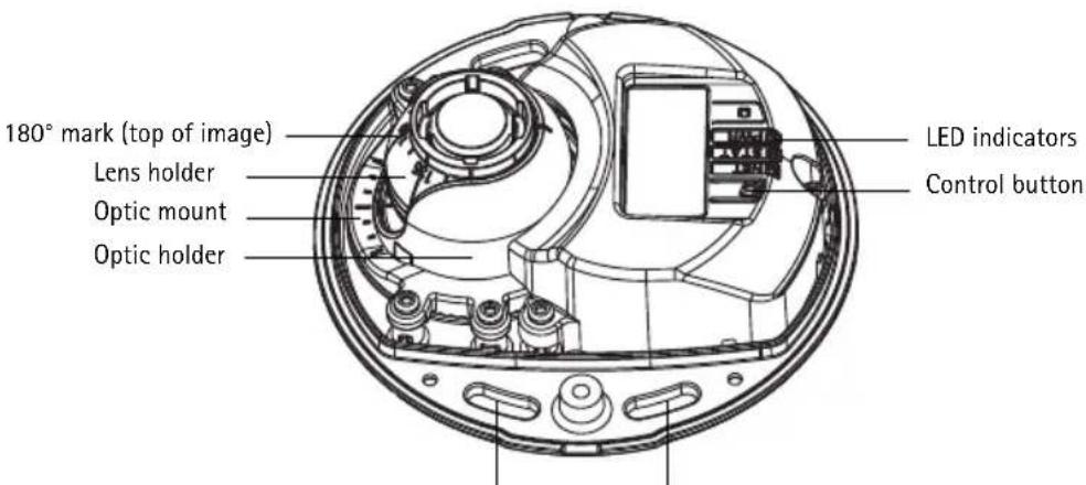
Use screws here to mount camera to mounting surface
natural_image
Line drawing of a mechanical device with a bulb and shaft, no text or symbols presentEthernet cable
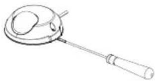
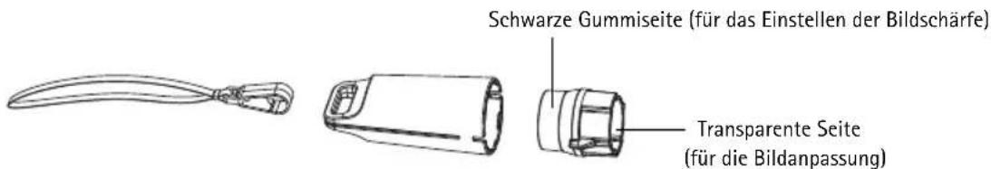
Lens tool
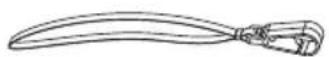
Black rubber side (for focus adjustment)
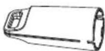
Transparent side
(for image adjustment)
Lens tool for adjusting image
natural_image
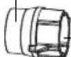
Technical line drawing of a mechanical assembly with no visible text or symbolsLens tool for adjusting focus
natural_image
Technical line drawing of a mechanical assembly with no visible text or symbolsLED indicators
| LED Color | Indication | |
| Net-work | Green Steady for connection to a 100 Mbit/s network. Flashes for network activity. | |
| Amber | Steady for connection to 10 Mbit/s network. Flashes for network activity. | |
| Unlit No network connection. Note: The Network LED can be configured to be unlit during normal operation. To configure, go to Setup > System Options > LED settings. See the online help files for more information. | ||
| Status Green Steady green for normal operation. Note: The Status LED can be configured to be unlit during normal operation, or to flash only when the camera is accessed. To configure, go to Setup > System Options > LED settings. See the online help files for more information. | ||
| Power Green Normal operation. | ||
Unit connectors
Network connector (AXIS M3113-R/AXIS M3114-R) - Female RJ-45 Ethernet connector for 10BaseT/100BaseTX. Supports Power over Ethernet. Using shielded cables is recommended.
Network connector (AXIS M3113-R M12/AXIS M3114-R M12) - Rugged female, D-coded M12 connector. Supports Power over Ethernet. Using shielded cables is recommended.
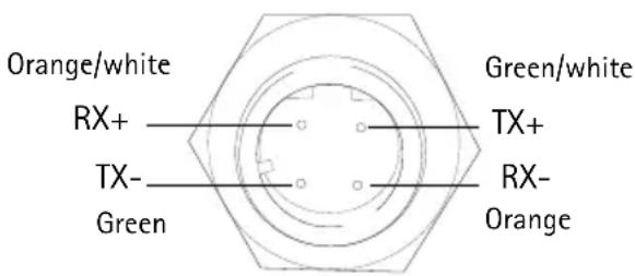
| M12 | |
| Data Power | |
| TX+ DC+/DC- | |
| RX+ DC-/DC+ | |
| TX- DC+/DC- | |
| RX- DC-/DC+ | |
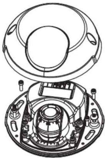
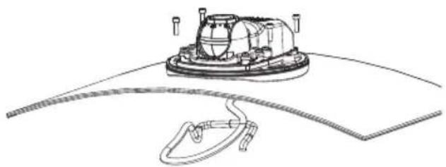
1 Install the hardware
natural_image
Line drawing of a ladle with a handle and circular opening (no text or symbols)- Remove the top cover from the camera unit by loosening the 2 screws. Then insert a screw driver into the slit in the bottom cover and lift.
- Depending on the kind of installation required, follow the appropriate instructions below.
Mount the camera without adaptor
- Adjust the drill template on the mounting surface so the camera's lens faces in the right direction, and drill four holes for the screws, and one hole for the cable.
- Align the screw slots in the camera with the screw holes in the mounting surface, and attach the camera with 4 screws.
Note:
It is recommended that each screw head with the washer does not exceed 5mm in height and 7mm in diameter.
Do not use a countersunk screw head.

natural_image
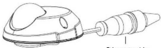
Technical line drawing of a mechanical assembly with no visible text or symbols- Attach the network cable to the camera's Ethernet cable.
Mount on a curved surface with an adaptor
- Place the adaptor on the curved mounting surface, align the two curvatures, and mark the two screw holes if drilling is required.
- Remove the protective paper from the adhesive tabs on the adaptor by pulling the ends.
- Place the adaptor in position and press down on the adhesive tabs.
Note:
Fasten the adaptor to the surface with two screws if the adhesive tabs do not stick to the surface material.
-
Place the drill template on the adaptor and turn the camera lens in the direction you want the camera to point.
-
Adjust the template to align the screw holes with the screw holes in the adaptor.
- Mark the cable hole, and mark the four screw holes if drilling is required.
- Drill the cable hole, and if required, 4 holes for the screws.
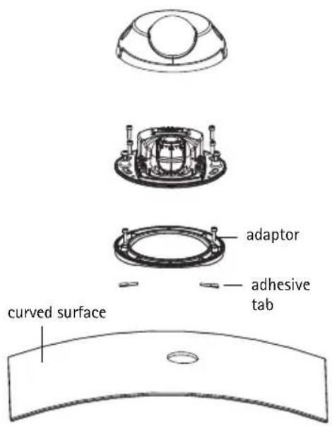
- Route the camera's Ethernet cable through the hole.
- Place the camera on the adaptor in the right direction and fasten with four screws.
Mount on a flat surface with an adaptor
- Place the adaptor on the mounting surface and position the slot for the cable where appropriate.
- Fasten the adaptor with three screws appropriate to the surface material.
- Fix the camera's Ethernet cable in the slot in the adaptor and press into place.
- Place the camera on the adaptor, and turn the camera so the lens faces the correct direction.
- Adjust so the screw slots on the camera are aligned with the screw holes in the adaptor, and attach the 4 screws (torque < 2.5 Nm).
- Attach the network cable to the camera's Ethernet cable.
Note:
Do not use a countersunk screw head.

natural_image
Technical line drawing of a mechanical device with hoses and components (no text or symbols)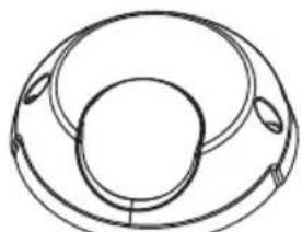
natural_image
Pure geometric diagram of concentric circles and rings without any text, numbers, or symbols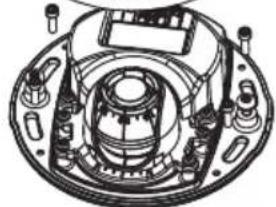
natural_image
Technical line drawing of a mechanical assembly with no visible text or symbols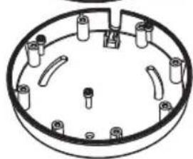
natural_image
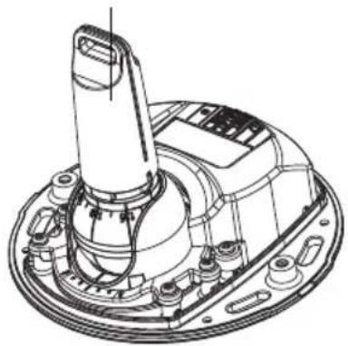
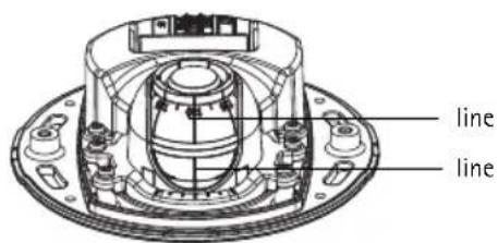
Technical line drawing of a circular mechanical component with multiple cylindrical pins and mounting holes (no text or symbols)② Adjust the direction of the lens
Fit the lens tool to the lens holder, and adjust the position of the lens by pointing the lens tool handle in the preferred direction (See illustration on page 4). This can be done vertically from 0 to 90 degrees, and 30 degrees to the left or the right on either side in increments of five.
The lens holder can also be rotated to adjust the image.
Align the ribs in the lens tool horizontally so that the image is also aligned horizontally.
Note:
The '0' mark on the lens holder indicates the bottom of the image and the '180' mark indicates the top, see Hardware overview above. If the camera is mounted upside down, adjust so the '0' mark is on top and the '180' mark below the lens.
natural_image
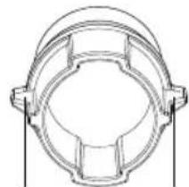
Technical line drawing of a mechanical component with symmetrical cutouts and mounting brackets (no text or symbols)Align ribs horizontally
The line inside of the bottom of the optic holder should be aligned with the line at the center of the optic mount.
3 Assign an IP address
The AXIS M31 Network Camera Series is designed for use on an Ethernet network and requires an IP address for access. Most networks today have a DHCP server that automatically assigns IP addresses to connected devices. If your network does not have a DHCP server, the AXIS M31 Network Camera Series will use 192.168.0.90 as the default IP address.
AXIS IP Utility and AXIS Camera Management are the recommended methods for setting an IP address in Windows. These free applications are available on the Axis Network Video Product CD supplied with this product, or they can be downloaded from www.axis.com/techsup Depending on the number of cameras you wish to install, use the method that suits you best.
| Method Recommended for Operating system | |||
 | AXIS IP UtilitySee page 9 | Single cameraSmall installations | Windows |
 | AXIS CameraManagementSee page 10 | Multiple camerasLarge installationsInstallation on a different subnet | Windows 2000Windows XP ProWindows 2003 ServerWindows Vista |
Notes:
- If you are unable to set the IP address, check for any firewall blocking the operation.
- For other methods of assigning or discovering the IP address, such as in other operating systems, see page 13.
AXIS IP Utility - single camera/small installation
AXIS IP Utility automatically discovers and displays Axis devices on your network. You can also manually set a static IP address through this application. AXIS IP Utility is available on the Axis Network Video Product CD, or it can be downloaded from www.axis.com/techsup
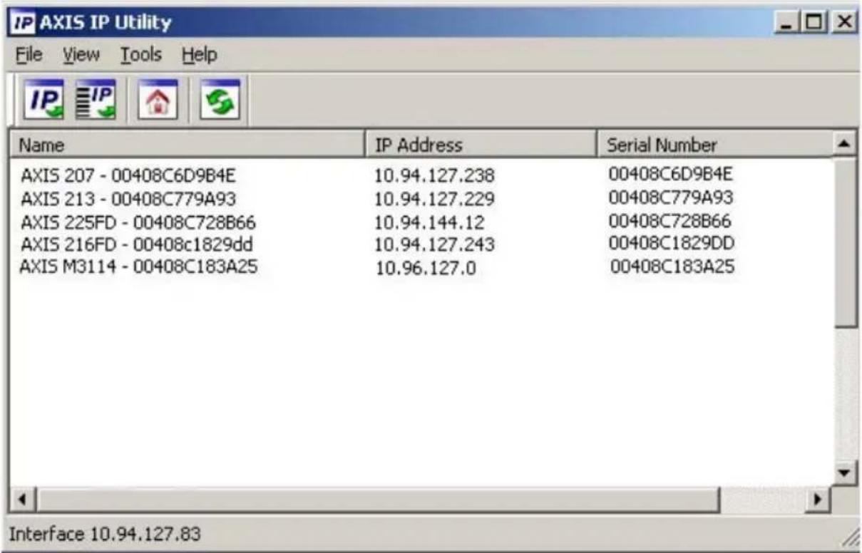
Note that you must install the network camera on the same network segment (physical subnet) as the computer running AXIS IP Utility.
Automatic discovery
- Check that the network camera is connected to the network and that power has been applied.
- Start AXIS IP Utility.
- When the camera appears in the window, double-click it to open its home page.
- See page 11 for instructions on how to assign the password.
Assign the IP address manually (optional)
- Acquire an unused IP address on the same network segment as your computer.
- Select AXIS M3113-R/AXIS M3114-R in the list.
- Click the button IP Assign new IP address to selected device and enter the IP address.
- Click the Assign button and follow the instructions.
- Click the Home Page button to access the camera's web pages.
- See page 11 for instructions on how to set the password.
AXIS Camera Management - multiple cameras/large installations
AXIS Camera Management can automatically discover multiple Axis devices, show connection status, manage firmware upgrades, and set IP addresses.
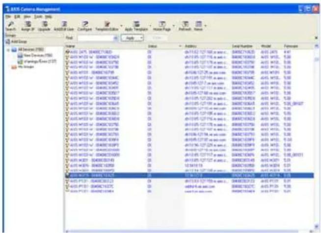
Automatic discovery
- Check that the camera is connected to the network and that power has been applied.
- Start AXIS Camera Management. When the camera appears in the window, right-click the link and select Live View Home Page.
- See page 11 for instructions on how to set the password.
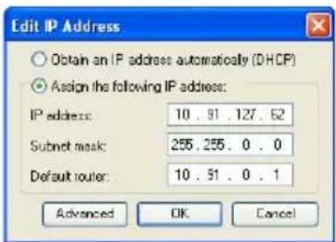
Assign an IP address in a single device
-
Select one of the AXIS M31 Network Camera Series in AXIS Camera Management and click the Assign IP button JP
-
Select Assign the following IP address and enter the IP address, the subnet mask, and default router the device will use.
-
Click OK.
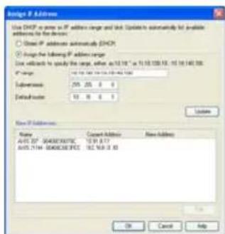
Assign IP addresses in multiple devices
AXIS Camera Management speeds up the process of assigning IP addresses to multiple devices, by suggesting IP addresses from a specified range.
-
Select the devices you wish to configure (different models can be selected) and click the Assign IP button JP
-
Select Assign the following IP address range and enter the range of IP addresses, the subnet mask, and default router the devices will use.
-
Click the OK button.

Set the password
To gain access to the product, the password for the default administrator user root must be set. This is done in the Configure Root Password dialog, which is displayed when the network camera is accessed for the first time.
To prevent network eavesdropping when setting the root password, this can be done via an encrypted HTTPS connection, which requires an HTTPS certificate.
To set the password via a standard HTTP connection, enter it in the Configure Root Password window.
To set the password via an encrypted HTTPS connection, follow these steps:
- Click the Create self-signed certificate button.
- Provide the requested information and click OK. The certificate is created and the password can now be set securely. All traffic to and from the network camera is encrypted from this point on.
- Enter a password and then re-enter it to confirm the spelling. Click OK. The password has now been configured.
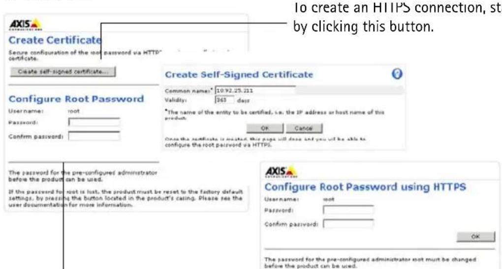
To configure the password directly via an unencrypted connection, enter the password here.
To create an HTTPS connection, start by clicking this button.
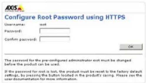
- To log in, enter the user name "root" in the dialog as requested.
Note: The default administrator user name root cannot be deleted.
- Enter the password as set above, and click OK. If the password is lost, the network camera must be reset to the factory default settings. See page 14.
If required, click Yes to install AMC (AXIS Media Control), which allows viewing of the video stream in Internet Explorer. You will need administrator rights on the computer to do this.
The Live View page of the network camera appears. The Setup link to the right gives you menu options for customizing the camera.
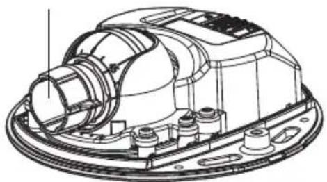
⑤ Adjust the focus
natural_image
Technical line drawing of a mechanical assembly with no visible text or symbols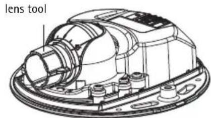
Fit black rubber side to adjust focus
Pull the lens tool from the lens tool holder, turn it around and fit the black rubber side to the lens. Adjust the focus. Check the image in the Live View page, and move the lens to the desired position using the transparent side of the lens tool. See illustration under Hardware overview, on page 4.
After replacing the top cover, the image may appear slightly out of focus due to the optical effect of the dome (especially in the case of tele/zoom lenses). To compensate, focus on an object slightly closer than the intended area. If possible, position the top cover in front of the lens while adjusting focus.
6 Complete the installation
To complete the installation, replace the top cover with care and tighten the captive screws. Ensure that the rubber gasket in the top cover and the ridge it fits into in the bottom plate are dust-free.
Changing the lens
To change the lens of the network camera:
- Fit the black rubber side of the lens tool to the lens holder and unscrew the lens.
- Remove the lens from the lens tool and fix the new lens to it.
- Fit the new lens to the camera and tighten the lens into place.
- Adjust the focus as described above.
Other methods of setting the IP address
All the methods listed the table below are enabled by default, and can be disabled.
| Use in operating system | Notes | |
| UPnPTM | Windows When enabled on your computer, the camera is automatically detected and added to "My Network Places." | |
| Bonjour | MAC OSX (10.4 or later) | Applicable to browsers with support for Bonjour. Navigate to the Bonjour bookmark in your browser (e.g. Safari) and click on the link to access the camera's web pages. |
| AXIS Dynamic DNS Service | All A free service from Axis that allows you to quickly and simply install your camera. Requires an Internet connection with no HTTP proxy. See www.axiscam.net for more information. | |
| ARP/Ping | All See below. The command must be issued within 2 minutes of connecting power to the camera. | |
| View DHCP server admin pages | All To view the admin pages for the network DHCP server, see the server's own documentation. | |
Set the IP address with ARP/Ping
- Acquire an IP address on the same network segment your computer is connected to.
- Locate the serial number (S/N) on the camera's label.
- Open a command prompt on your computer and enter the following commands:
| Windows syntax Windows example | |
| arp -s <IP Address> <Serial Number> ping -l 408 -t <IP Address> | arp -s 192.168.0.125 00-40-8c-18-10-00 ping -l 408 -t 192.168.0.125 |
| UNIX/Linux/Mac syntax UNIX/Linux/Mac example | |
| arp -s <IP Address> <Serial Number> temp ping -s 408 <IP Address> | arp -s 192.168.0.125 00:40:8c:18:10:00 temp ping -s 408 192.168.0.125 |
- Check that the network cable is connected to the camera and then start/restart the camera, by disconnecting and reconnecting power.
- Close the command prompt when you see 'Reply from 192.168.0.125: ...' or similar.
- In your browser type http://
in the Location/Address field and press Enter.
Notes:
- To open a command prompt in Windows: from the Start menu, select Run... and type cmd. Click OK.
- To use the ARP command on a Mac OS X, use the Terminal utility in Application > Utilities.
Resetting to the Factory Default Settings
This will reset all parameters, including the IP address, to the Factory Default settings:
- Disconnect the network cable from the camera.
- Remove the top cover by loosening the 2 captive screws.
- Press and hold the Control button and reconnect the power\network cable.
- Keep the Control button pressed until the Status indicator displays amber (this may take up to 15 seconds).
- Release the Control button. When the Status indicator displays green (which can take up to 1 minute) the process is complete and the camera has been reset.
- Re-assign the IP address, using one of the methods described in this document.
It is also possible to reset parameters to the original factory default settings via the web interface. For more information, please see the online help or the user's manual.
Further information
The user's manual is available from the Axis Web site at www.axis.com or from the Axis Network Video Product CD supplied with this product.
Tip!
Visit www.axis.com/techsup to check if there is updated firmware available for your network camera. To see the currently installed firmware version, click the Basic Configuration menu item in the product's web page.
Série AXIS M31
natural_image
Technical line drawing of a mechanical assembly with no visible text or symbolsnatural_image
Technical line drawing of a mechanical assembly with no visible text or symbolsTémoins DEL
natural_image
Line drawing of a magnifying glass with handle and circular lens (no text or symbols)natural_image
Technical line drawing of a mechanical assembly with no visible text or symbolsnatural_image
Technical line drawing of a mechanical device with hoses and components (no text or symbols)natural_image
Abstract line drawing of a circular mechanical or architectural component with three concentric rings and two small oval cutouts (no text or symbols)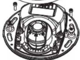
natural_image
Technical line drawing of a mechanical assembly with no visible text or symbols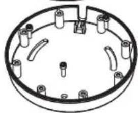
natural_image
Technical line drawing of a circular mechanical component with multiple cylindrical pins and mounting holes (no text or symbols)natural_image
Technical line drawing of a mechanical component with symmetrical cutouts and mounting brackets (no text or symbols)natural_image
Technical line drawing of a mechanical assembly with no visible text or symbolsdispositif de
natural_image
Line drawing of a mechanical device with a bulb and threaded shaft (no text or symbols)Ethernet-Kabel
Objektivwerkzeug
natural_image
Technical line drawing of a mechanical assembly with no visible text or symbolsnatural_image
Technical line drawing of a mechanical assembly with no visible text or symbolsLED-Anzeigen
natural_image
Line drawing of a magnifying glass with a handle and circular lens (no text or symbols)natural_image
Technical line drawing of a mechanical assembly with no visible text or symbolsnatural_image
Technical line drawing of a mechanical device with curved base and attached tubing (no text or symbols)natural_image
Pure diagram of concentric circular rings with no text or symbols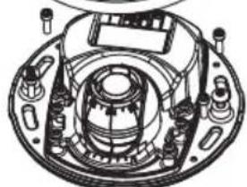
natural_image
Technical line drawing of a mechanical assembly with no visible text or symbols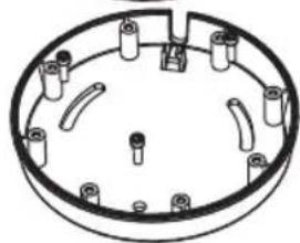
natural_image
Technical line drawing of a circular mechanical component with multiple cylindrical pins and mounting holes (no text or symbols)
natural_image
Technical line drawing of a mechanical component with symmetrical cutouts and mounting brackets (no text or symbols)natural_image
Technical line drawing of a mechanical assembly with no visible text or symbols
natural_image
Line drawing of a mechanical device with a cylindrical shaft and circular top component (no text or symbols)Cavo Ethernet
natural_image
Technical line drawing of a mechanical assembly with no visible text or symbolsnatural_image
Technical line drawing of a mechanical assembly with no visible text or symbolsIndicatori LED
natural_image
Line drawing of a magnifying glass with a handle and circular lens (no text or symbols)natural_image
Technical line drawing of a mechanical assembly with no visible text or symbolsnatural_image
Technical line drawing of a mechanical device with hoses and components (no text or symbols)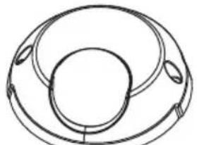
natural_image
Pure technical line drawing of a circular mechanical component with no text or symbols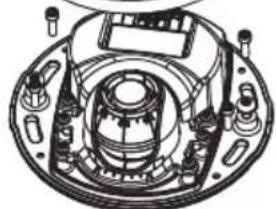
natural_image
Technical line drawing of a mechanical assembly with no visible text or symbols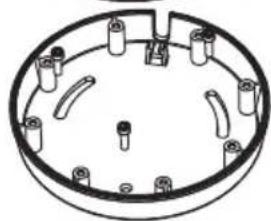
natural_image
Technical line drawing of a circular mechanical component with multiple cylindrical pins and mounting holes (no text or symbols)natural_image
Technical line drawing of a mechanical component with symmetrical cutouts and mounting brackets (no text or symbols)natural_image
Technical line drawing of a mechanical assembly with no visible text or symbolsnatural_image
Technical line drawing of a mechanical assembly with no visible text or symbolsIndicadores LED
natural_image
Line drawing of a ladle with handle and spout (no text or symbols)natural_image
Technical line drawing of a mechanical assembly with no visible text or symbolsnatural_image
Technical line drawing of a mechanical device with hoses and components (no text or symbols)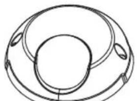
natural_image
Abstract geometric diagram with concentric circles and curved lines, no text or symbols present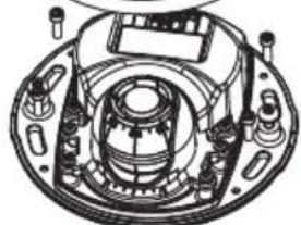
natural_image
Technical line drawing of a mechanical assembly with no visible text or symbols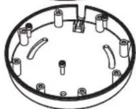
natural_image
Technical line drawing of a circular mechanical component with multiple cylindrical pins and mounting holes (no text or symbols)natural_image
Technical line drawing of a mechanical component with symmetrical cutouts and mounting brackets (no text or symbols)natural_image
Technical line drawing of a mechanical component with no visible text or symbolsnatural_image
Technical line drawing of a mechanical assembly with no visible text or symbolsAXIS M31 Network Camera Series Printed: February 2010
© Axis Communications AB, 2009-10 Part No. 37711
- About this Document
- Legal Considerations
- Electromagnetic Compatibility (EMC)
- Equipment Modifications
- Liability
- RoHS
- WEEE Directive
- Support
- AXIS M31 Series Installation Guide
- Installation steps
- Hardware overview
- Lens tool
- LED indicators
- Unit connectors
- Install the hardware
- Mount the camera without adaptor
- Note:
- Mount on a curved surface with an adaptor
- Mount on a flat surface with an adaptor
- ② Adjust the direction of the lens
- Assign an IP address
- Notes:
- AXIS IP Utility - single camera/small installation
- Automatic discovery
- Assign the IP address manually (optional)
- AXIS Camera Management - multiple cameras/large installations
- Assign an IP address in a single device
- Assign IP addresses in multiple devices
- Set the password
- ⑤ Adjust the focus
- Complete the installation
- Changing the lens
- Other methods of setting the IP address
- Set the IP address with ARP/Ping
- Resetting to the Factory Default Settings
- Further information
- Tip!
- Série AXIS M31
- Objektivwerkzeug
- Indicatori LED
- Indicadores LED
Brand : AXIS
Model : M3113-R
Category : Surveillance Camera