
CMV980RVS - Range hood Pelgrim - Free user manual and instructions
Find the device manual for free CMV980RVS Pelgrim in PDF.


| Product type | Range hood |
| Brand | Pelgrim |
| Model | CMV980RVS |
| Dimensions (LxDxH) | 90 x 50 x (85-110) cm |
| Net weight | 15 kg |
| Power supply | 220-240 V, 50 Hz, 200 W |
| Max extraction power | 600 m³/h |
| Noise level | 65 dB (A) |
| Energy class | A |
| Lighting | LED, 2 x 1.5 W |
| Control type | Touch electronic |
| Grease filter | Aluminium, washable |
| Charcoal filter | Optional |
| Extraction/recirculation function | Yes |
| Number of speeds | 3 + intensive |
| Installation | Wall-mounted or island |
| Material | Stainless steel |
| Warranty | 2 years |
| Maintenance | Clean the grease filter every month |
| Safety | Automatic shut-off possible |
Frequently Asked Questions - CMV980RVS Pelgrim
User questions about CMV980RVS Pelgrim
0 question about this device. Answer the ones you know or ask your own.
Ask a new question about this device
Download the instructions for your Range hood in PDF format for free! Find your manual CMV980RVS - Pelgrim and take your electronic device back in hand. On this page are published all the documents necessary for the use of your device. CMV980RVS by Pelgrim.
USER MANUAL CMV980RVS Pelgrim
natural_image
Hand inserting a plastic cover into an open shelf (no text or symbols visible)CMV680ERVS
CMV980ERVS
Handleiding
afzuigkap
natural_image
Diagram of a vertical structure with arrows indicating airflow or movement, no text or symbols presentnatural_image
Diagram of a brick wall with a vertical structure and directional arrows indicating movement or force (no text or symbols)natural_image
3D mechanical assembly diagram showing internal components and a directional arrow (no text or symbols)2
natural_image
3D mechanical assembly diagram showing a component with an arrow indicating direction (no text or symbols)
natural_image
3D diagram of a mechanical component with labeled parts (1 and 2), showing internal structure and directional arrows (no text or symbols beyond labels)natural_image
Diagram showing two steps of a solar panel installation, with arrows indicating direction (no text or symbols present)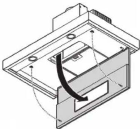
natural_image
Technical line drawing of a mechanical assembly with internal components and a curved arrow indicating motion (no text or symbols)natural_image
Diagram of a device with an open lid and internal components, showing a lock mechanism (no text or symbols present)natural_image
Illustration of a hand holding a screwdriver, a circular component with a lid, and a circular dial with arrows (no text or symbols)Algemeen
natural_image
Diagram of a mechanical or electrical component with directional arrows and a central hanging component (no text or symbols)Montage





natural_image
Technical diagram of a mechanical assembly with a curved arrow indicating motion or force, no visible text or symbols
natural_image
Technical diagram of a mechanical assembly with an inset showing a rotating component (no text or symbols present)
natural_image
Technical diagram showing a mechanical assembly with an inset view of a tool interacting with a component (no text or symbols present)

natural_image
Isometric line drawing of a mechanical device with a curved arrow and label '11' (no text or symbols on the device itself)
natural_image
Technical illustration of a mechanical device with a cylindrical component mounted on a base, labeled '15' (no text or symbols on the diagram itself)
natural_image
Technical line drawing of a mechanical device with a coiled spring and control panel (no text or symbols)
natural_image
Isometric diagram of a mechanical device with a coiled spring and housing, showing motion arrows (no text or symbols)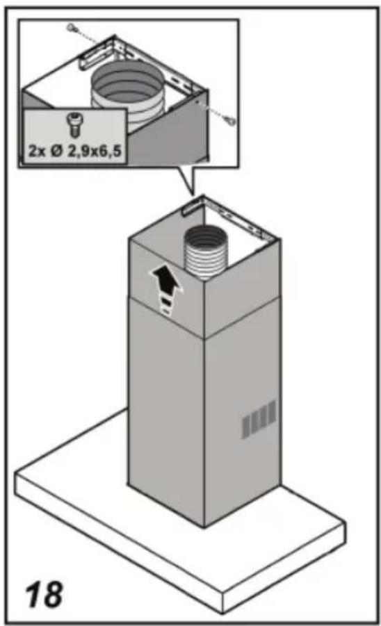


natural_image
Technical diagram showing a mechanical assembly with labeled parts and an inset view of a tool interacting with a component (no text or symbols present)
natural_image
Technical diagram showing a mechanical assembly with an inset view of a rotating component (no text or symbols present)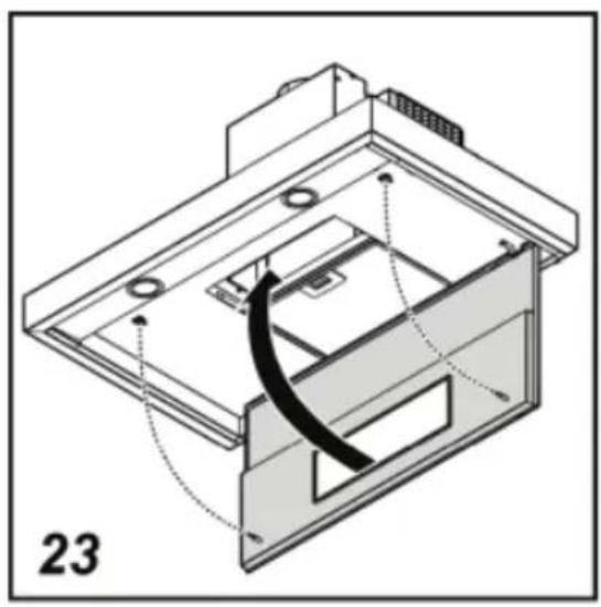
natural_image
Technical diagram of a device with internal components and a curved black line indicating a motion or assembly (no text or symbols present)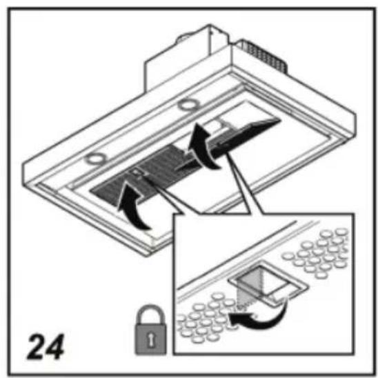
natural_image
Symbol of a trash bin with crossed x's and no text or numbers, representing waste sorting or disposal (no text present)natural_image
Architectural diagram showing a brick wall with ventilation ducts and a cabinet, no text or symbols presentnatural_image
Diagram of a vertical structure with brick wall and adjacent panel, showing airflow or movement arrows (no text or symbols)natural_image
3D mechanical assembly diagrams showing two views of a device with internal components and directional arrows (no text or symbols)natural_image
Diagram showing two steps of a mechanical assembly with grid-like components and directional arrows (no text or symbols)natural_image
Diagram showing a device with internal components and a lock mechanism, no text or symbols present
natural_image
Technical diagram of a mechanical assembly with internal components and a curved arrow indicating motion (no text or symbols)natural_image
Technical diagram of a mechanical assembly with an inset showing a lock mechanism (no text or symbols present)natural_image
Illustration of three hand tools: a screwdriver, a circular dial with a pointer, and a circular dial with arrows (no text or symbols)Généralités

natural_image
Diagram of a mechanical or electrical component with directional arrows and a central hanging component (no text or symbols)Montage


natural_image
Technical diagram of a mechanical assembly with a curved arrow indicating motion or force, no visible text or symbols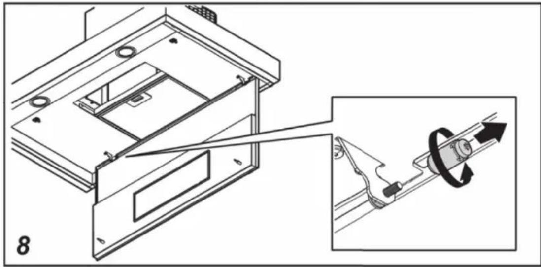
natural_image
Technical diagram of a mechanical assembly with an inset showing a rotating component (no text or symbols present)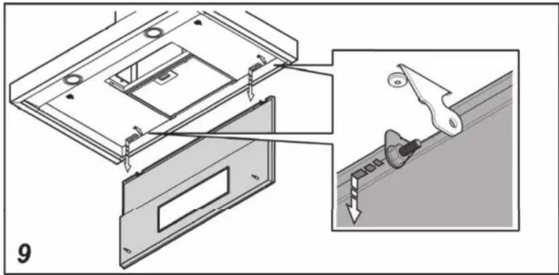
natural_image
Technical diagram showing a mechanical assembly with an inset view of a tool interacting with a component (no text or symbols present)

natural_image
Isometric line drawing of a mechanical device with a curved arrow and label '11' (no text or symbols on the device itself)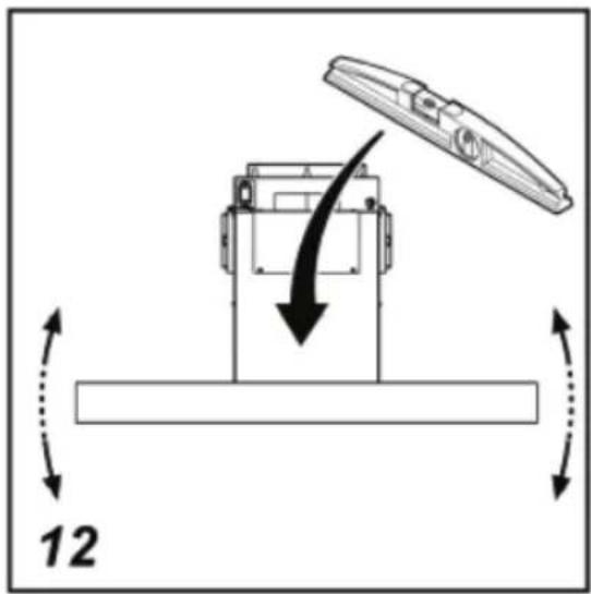

natural_image
Technical illustration of a mechanical device with a cylindrical component mounted on a base, labeled '15' (no text or symbols on the diagram itself)
natural_image
Technical line drawing of a mechanical device with a coiled spring and control panel (no text or symbols)
natural_image
Isometric diagram of a mechanical device with a coiled spring and housing, labeled '17' (no text or symbols on the diagram itself)


natural_image
Technical diagram showing a mechanical assembly with labeled parts and an inset view of a tool interacting with a component (no text or symbols present)
natural_image
Technical diagram showing a mechanical assembly with an inset view of a rotating component (no text or symbols present)
natural_image
Technical diagram of a device with internal components and a curved black line indicating a motion or assembly (no text or symbols present)
natural_image
Symbol of a trash bin with crossed x-marks and a blank base (no text or numbers)natural_image
3D mechanical assembly diagram showing internal components with a central component and upward arrow (no text or symbols)2

natural_image
3D diagram of a mechanical device with an arrow indicating direction (no text or symbols)
natural_image
3D diagram of a mechanical component with labeled parts (1 and 2), showing internal structure and directional arrows (no text or symbols beyond labels)natural_image
Diagram showing two steps of a mechanical assembly with arrows indicating direction (no text or symbols present)
natural_image
Technical diagram of a mechanical assembly with internal components and directional arrows (no text or symbols)natural_image
Technical diagram of a device with an open lid and internal components, showing a close-up view of a lock mechanism (no text or symbols present)natural_image
Illustration of a hand holding a screwdriver, a circular component with a knob, and a circular dial with arrows (no text or symbols)Allgemein
natural_image
Diagram of a mechanical or electrical component with directional arrows and a central hanging component (no text or symbols)Montage




natural_image
Technical diagram of a mechanical assembly with a curved arrow indicating motion or force, no visible text or symbols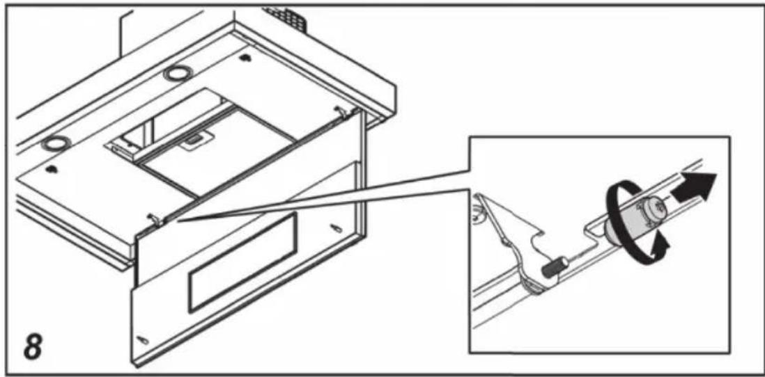
natural_image
Technical diagram of a mechanical assembly with an inset showing a rotating component (no text or symbols present)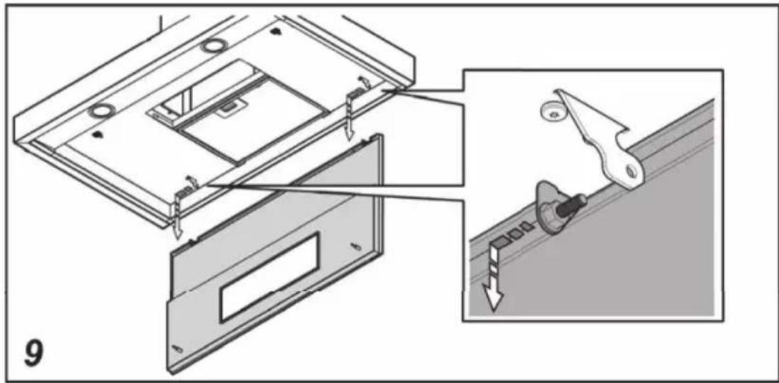
natural_image
Technical diagram showing a mechanical assembly with an inset view of a tool interacting with a component (no text or symbols present)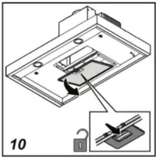

natural_image
Isometric line drawing of a mechanical device with a curved arrow and label '11' (no text or symbols on the device itself)


natural_image
Technical illustration of a mechanical device with a cylindrical component mounted on a base, labeled '15' (no text or symbols on the diagram itself)
natural_image
Technical line drawing of a mechanical device with a coiled spring and control panel (no text or symbols)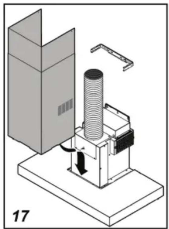
natural_image
Isometric diagram of a mechanical device with a coiled spring and housing, labeled '17' (no text or symbols on the diagram itself)


natural_image
Technical diagram showing a mechanical assembly with labeled parts and an inset view of a tool interacting with a component (no text or symbols present)
natural_image
Technical diagram showing a mechanical assembly with an inset view of a rotating component (no text or symbols present)
natural_image
Technical diagram of a device with internal components and a curved black line indicating a motion or assembly (no text or symbols present)
natural_image
Symbol of a trash bin with crossed x's and no text or numbers, representing waste sorting or disposal (no text present)Extraction systems 6
Extraction system and electric flap
Extractor hoods for mechanical ventilation systems 7
Motorless extractor hoods 7
Quiet, efficient and energy-saving 8
Operation
Switching on/off 9
Adjusting the speed 9
Setting the switch-off time 9
Switching the light on/off 10
Grease filter signal 10
Charcoal filter signal 10
Maintenance
Cleaning 12
Removing the grease filters 13
Replacing the carbon filter 14
Replacing the lights 14
Installation
General 15
Electrical connection 16
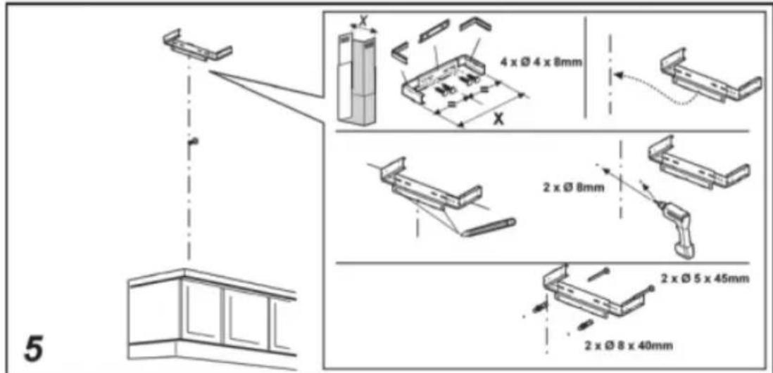
Mounting the extractor hood 17
Environmental aspects
Disposal of package and appliance 24
Introduction
You have selected a Pelgrim extractor hood. Optimum ease of use and simple operation were the most important factors in the development of this product.
The extractor hood provides maximum extraction effect. Cooking smells are reduced optimal. The CMV680 and CMV980 are specially designed for use on a central extraction system and are fitted with an electric flap.
This manual describes how you can make the best possible use of your extractor hood. You can find information in it about the controls and background information about how the appliance works. You will also find maintenance tips.
The safety instructions that are important during the installation are included in the installation guide, which is supplied separately and is meant for the installer.
Read the manual thoroughly before using the appliance, and store these instructions in a safe place for future reference.
Enjoy your cooking!
Control panel

1 On/Off button
2 Fan button (4 settings)
3 Display
4 Light button
5 Timer button
Attention!

Make sure the appliance is installed by an authorised installer (see “Installation” chapter). Do not connect the appliance to the flow network before completing the installation.
- Connect the appliance in accordance with the applicable regulations in your area.
- We advise you to wear protective work gloves during the installation of the cooker hood due to possible sharp edges.
- The appliance has been manufactured in accordance with the latest safety standards. However we do advise that mentally handicapped, disabled or retarded individuals do not use this appliance without the proper supervision of a competent person. The same applies to children.
- Never use the cooker hood when the grease filter has not been properly installed!
- Do not lean against the cooker hood.
- The hood must never be used as a support surface unless specifically indicated.
- Make sure there is sufficient circulation when you use the cooker hood above a gas cooker.
- The exhaust exit must never be connected to a smoke duct which is also used for other heating appliances.
- Never flambé under the cooker hood and always clean the filters on time. Frying needs to be done under constant supervision to prevent the heated fat from catching fire.
- The cooker hood needs to be cleaned regularly (at least once a month) on the inside as well as on the outside. When the filters are insufficiently cleaned or replaced, this will result in a fire hazard.
- If the connection cable becomes damaged, it should be replaced by the manufacturer's service department or by a person with equivalent qualifications, in order to prevent dangerous situations from arising.
- NB! Extended use can lead to condensation forming on the extractor hood. This condensation can be removed easily with a dry cloth.
Attention!

- First disconnect the appliance from the socket when you replace the lights!
- Only use identical lamps with the wattage indicated. Only use the cooker hood with lamps installed to reduce the risk of electrical shock.
- The grease filters become hot during operation. Wait a minimum of 30 minutes after cooking before cleaning it.
- The main current must be switched off during reparation or cleaning. Remove the plug from the mains current or turn the switch in the meter cupboard to zero.
- Grease and oil are flammable when they are overheated. Stay in the vicinity of the cooker when preparing food.
- We will not accept any responsibility for any faults, damage or fires caused to the appliance as a result of the non-observance of the instructions included in this manual.
Extraction systems

These hoods have two extraction systems working parallel:
- As an extractor hood on a CMV extraction duct:
The cooking vapours are sucked in and filtered and then carried outside via the CMV system.
- Recirculation hood:
As a recirculation hood, the grease particles and the smell in the extracted vapours are filtered. The air that has been sucked in is not carried outside but recirculates in the kitchen.

natural_image
Diagram of a brick wall with a vertical structure and directional arrows indicating movement or force (no text or symbols)Extractor hoods for mechanical ventilation systems
With central mechanical ventilation systems, the normal extraction rate is often not high enough in the kitchen. Pelgrim has developed and patented its own unique system. This system fits all of the leading systems for central mechanical ventilation (CMV).
The system is a combination of two separate extraction systems: mechanical ventilation and recirculation. On the one hand, optimum use is made of the existing central mechanical ventilation system, and on the other hand, a recirculation system is used to increase the rate of the air being extracted.
- CMV
- Recirculation
1

natural_image
3D mechanical assembly diagram showing internal components and a directional arrow (no text or symbols)2

natural_image
3D mechanical assembly diagram showing a component with an arrow indicating direction (no text or symbols)
natural_image
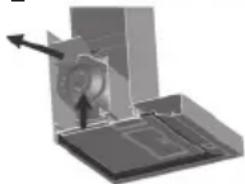
3D diagram of a mechanical component with labeled parts (1 and 2), showing internal structure and directional arrows (no text or symbols beyond labels)The extractor hoods are fitted with a washable long-life charcoal filter, and are quieter and more energy-efficient than conventional extraction hoods. Almost all odours and vapours are eliminated even during extended periods of cooking. Thanks to the recirculation system, the air does not all disappear outside. That is because some of the extracted air is returned into the kitchen after filtering. This means you use less energy.
Motorless extractor hoods
Pelgrim also manufactures a complete range of motorless extractor hoods, suitable for central mechanical ventilation systems with an electrically operated flap for an hermetic seal. The electric flap opens and closes within a few seconds. Once it is open or closed, the electric motor is turned off which saves energy.
Another ‘green’ advantage is that the flap stops warm air being sucked outside via the extractor hood, which reduces your heating costs. Because the system is hermetically sealed after cooking, this makes annoying whistling noises a thing of the past.
Quiet, efficient and energy-saving
The new developed system and the electric flap are now both integrated in your extractor hood. This ensures the best possible air quality in your kitchen. Cooking odours and grease are extracted very effectively, the efficiency is improved, and the extractor hood has become even quieter.
Switching on/off

Make sure the CMV system in your home is switched to the highest setting.
- Press the On/Off button.
The electric flap is opened; the hood switches on in the first setting. The display shows '1'. - To switch off the hood, press the On/Off button again.
The electric flap is closed; the hood switches off. '1' will disappear.
▶ After switching on, wait at least 20 seconds before switching the hood back off. The electric flap needs this time to open/close.
Adjusting the speed

The fan has four settings.
- Press the fan button to go directly to the first setting.
The electric flap is opened; the hood switches on in the first setting. The display shows '1'.
If the hood is already running in the first setting (switched on with the On/Off button), the hood switches directly to the second setting.
- By pressing the fan button (several times), the hood switches from the first setting to a higher setting. Setting 4 is the intensive setting; '4' will blink in the display.
▶If you choose setting 4, the hood switches automatically to setting 3 after 5 minutes. You can change the setting within these 5 minutes by pressing the fan button (several times). The electric flap stays open. To switch off the hood completely, press the On/Off button (the electric flap closes).
Setting the switch-off time

You can use the timer button to set a period of time after which the hood switches off automatically. This is only possible with the hood switched on in setting 2, 3 or 4. You can use this feature, for example, when you have finished cooking, but still want the extractor hood to keep running for a while.
- Be sure the hood is switched on and that it has been set to setting 2, 3 or 4.
If you press the timer button with the hood in setting 2, the hood will switch off after 15 minutes.
- If you press the timer button with the hood in setting 3, the hood will switch off after 10 minutes. - If you press the timer button with the hood in setting 4, the hood will switch off after 5 minutes.
If the switch-off time has been set, a dot will blink in the display.
- You can switch off the hood completely during the switch-off time by pressing the On/Off button or the timer button.
- If you press the fan button during the switch-off time, the hood keeps active and will not switch off automatically.
Switching the light on/off

- Press the light button.
The lighting comes on. - Press the light button again.
The lighting goes off.
Grease filter signal
- The grease filter signal occurs after 40 hours of operation and is shown in the display with number 1 flashing. Such signal means that the grease filter needs to be cleaned. The signal is visible when the hood is ON. On page 12 and 13 you can read how to clean the grease filters. Have you replaced the grease filters, you can deactivate the grease filter signal by pressing the On/Off button for at least three seconds, until it goes off.
▶If the charcoal filter has to be cleaned also, numbers 1 and 2 flash alternately in the display. To reset, carry out the procedure to deactivate the signal twice.
Charcoal filter signal
- The charcoal filter signal occurs after 320 hours of operation and is shown in the display with number 2 flashing. Such signal means that the charcoal filter needs to be cleaned. The signal is visible when the hood is ON. On page 13 and 14 you can read how to clean the charcoal filter. Have you replaced the charcoal filter, you can deactivate the charcoal filter signal by pressing the On/Off button for at least three seconds, until it switches off.
If the grease filters have to be cleaned too, numbers 1 and 2 flash alternately in the display. To reset, carry out the procedure to deactivate the signal twice.

- If you want this signal to appear again when the charcoal filter needs to be cleaned, then you have to reactivate the signal; turn off the extractor hood with the on/off button, and then press the fan button and light button at the same time for at least three seconds. You will see the numbers '1' and '2' flashing alternately in the display for two seconds. The signal will then start flashing the next time the charcoal filter needs to be cleaned.

- If you do not want this signal to appear again when the charcoal filter needs to be cleaned, you can deactivate the signal; turn off the extractor hood with the on/off button, and then press the fan button and light button at the same time for at least three seconds. The number '1' will flash in the display for two seconds. The signal when the charcoal filter needs to be cleaned will no longer appear.
Cleaning

Attention!
Before performing any maintenance operation, isolate the hood from the electrical supply by switching off at the connector and removing the connector fuse. Or if the appliance has been connected through a plug and socket, then the plug must be removed from the socket.
The cooker hood should be cleaned regularly (at least with the same frequency with which you carry out maintenance of the grease filters) internally and externally. Do not use abrasive products.
Do not use alcohol!

Attention!
Failure to carry out the basic cleaning recommendations of the cooker hood and replacement of the filters may cause risk of fire. Therefore, we recommend observing these instructions.
The manufacturer declines all responsibility for any damage to the motor or any fire damage linked to inappropriate maintenance or failure to observe the above safety recommendations.
Cooker hood
Clean the cooker hood with soapy water and a soft cloth. Then wipe with clean water to rinse. Do not use aggressive cleaning agents such as soda. The cooker hood paintwork will stay looking nice if you wax it occasionally.
Stainless steel extractor hoods
Do not use any sort of scourer. Treat with a stainless steel care product and polish in the direction of the structure of the stainless steel.
Metal grease filters
These must be cleaned once a month (or when the filter saturation indication system indicates this necessity) using non aggressive detergents, either by hand or in the dishwasher, which must be set to a low temperature and a short cycle. The openings must be placed downwards to let the water run out of the filters. The cleaning agents will make the aluminium filter turn dull, this is normal.
Long life charcoal filter
The charcoal filter with frame can be washed once every six months (or when the filter saturation indication system indicates this necessity)

natural_image
Diagram showing two views of a solar panel structure with arrows indicating assembly direction (no text or symbols)using hot water and a suitable detergent, or in a dishwasher at 65^ C (if the dishwasher is used, select the full cycle function and leave dishes out).
Eliminate excess water without damaging the filter, then remove the mattress located inside the plastic frame and put it in the oven for 10 minutes at 100 °C to dry completely. Replace the mattress every 3 years and when the cloth is damaged. You can rinse out the mattress max. five times.
Removing the grease filters
Switch off the electricity! Remove the plug from the socket or switch off the electricity at the mains.
The hood has two different grease filters:
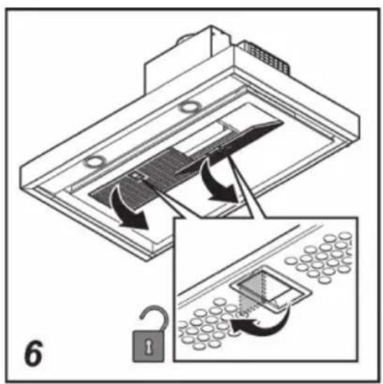
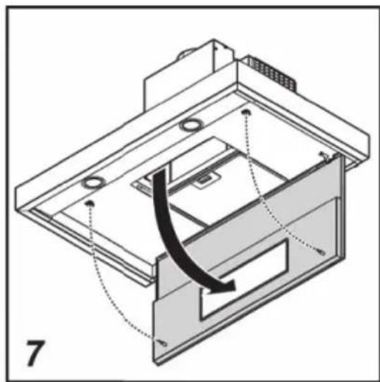
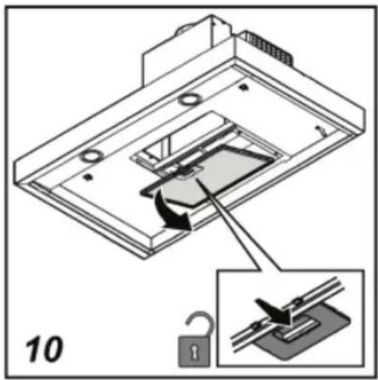
- Open the catch to release the grease filter of the CMV and then tilt the grease filter down toward you. Do this with the other grease filter as well (CMV980).
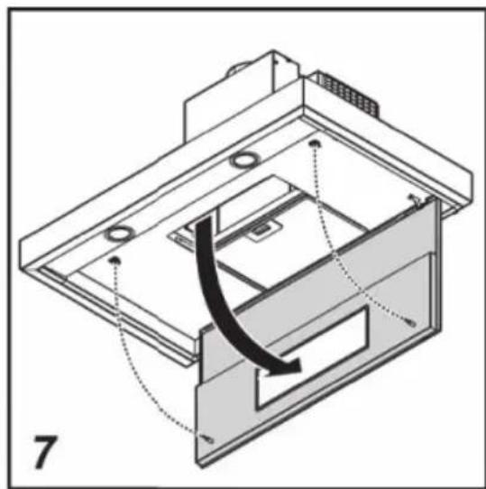
- Pull the panel that holds the grease filter(s) downwards.


natural_image
Technical diagram of a mechanical assembly with internal components and directional arrows (no text or symbols)- Push in the stud to release the recirculation grease filter, and tilt the grease filter down toward you.

natural_image
Diagram of a device with an open lid and internal components, showing a lock mechanism (no text or symbols present)Removing the long life charcoal filter
Switch off the electricity! Remove the plug from the socket or switch off the electricity at the mains.
- Pull the panel (that holds the grease filter(s) of the CMV) downwards.
- Push in the stud to release the recirculation grease filter, and tilt the grease filter down toward you.
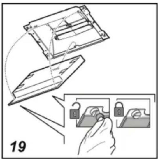
- Behind the grease filter you can find the charcoal filter. Remove the filter holder frame by turning the knobs (*) 90° that affix the chimney to the cooker hood.


Important:
- Saturation of the activated charcoal will eventually occur after more or less prolonged use, depending on the type of cooking and how frequently the grease filter is cleaned.
- You can wash and reuse the carbon filter. Replace the mattress every 3 years and when the cloth is damaged.
- You can rinse out the mattress max. five times.
Replacing the lights
- Remove the lamp cover and replace the halogen light bulb with a replacement bulb with a maximum output power of 20 Watts. Re-close the lamp cover.

natural_image
Illustration of a hand holding a screwdriver, a close-up of a circular component, and a circular dial with arrows (no text or symbols)General
This appliance should be connected to the power supply by a recognized fitter who is familiar with, and works according to the correct safety regulations. This appliance meets the European requirements.

Important to know:
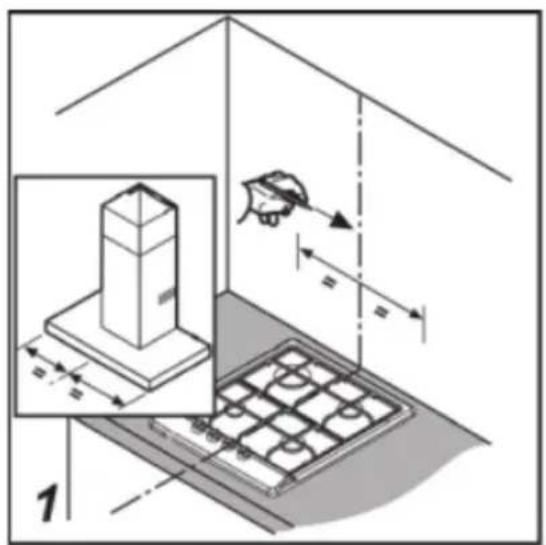
- The minimum distance between the supporting surface for the cooking vessels on the gashob and the lowest part of the range hood must be not less than 65 cm. For use with an electric, ceramic or induction hob, this distance must be at least 55 cm.
- If the cooker hood is to be fitted to an existing duct no other appliances, such as a geyser or heater, may be connected to that same duct.
- Consider local regulations with respect to the ventilation of gas appliances.
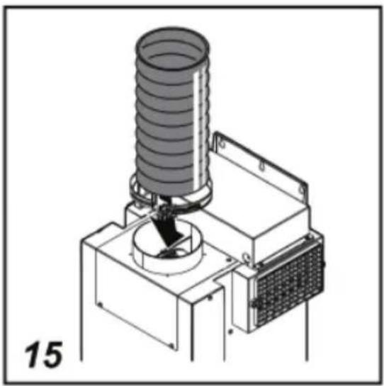
- The shorter the duct, and the fewer the bends in it, the better the cooker hood will work.
- Before you start drilling check that there are no installation cables present.
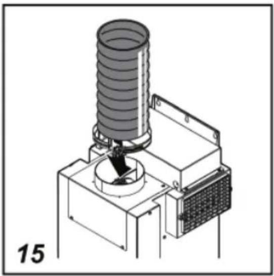
- The connecting pipe for the cooker hood has a diameter of 125 mm. It is best also to use a flue pipe of the same diameter.
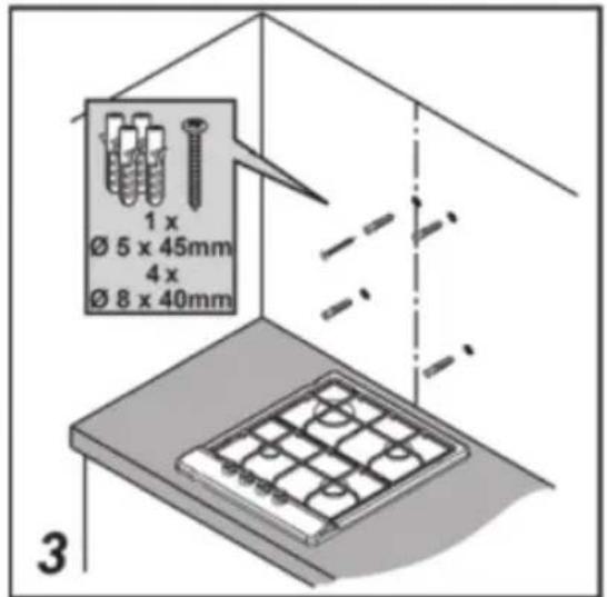
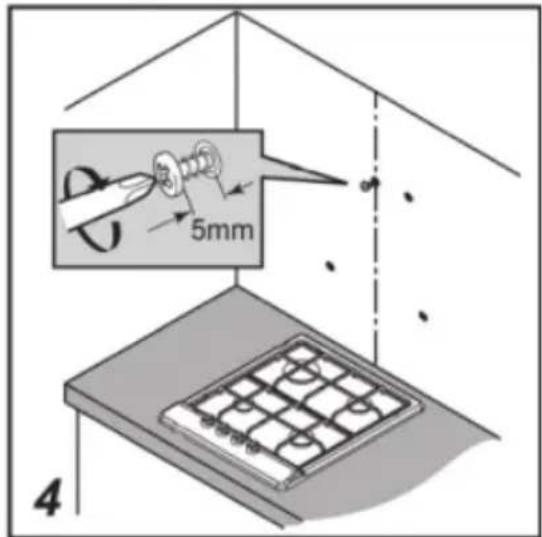
- The installation material supplied with this range hood is designed for fixing to reinforced concrete or masonry walls. For some types of walls you may need special plugs and screws.
Electrical connection
The appliance has been manufactured as a class I. The cable must be connected to an earthed socket!
Make sure the supply voltage ratings correspond with those stated on the appliance data plate. The connection to the mains is carried out as follows:
BROWN = phase L
BLUE = phase N
YELLOW/GREEN = earth
This extractor hood has been provided with a power plug. When installing the hood, make sure that this plug remains accessible. We recommend installing the wall socket out of view, behind the chimney cover.

Attention:
If you want to make a fixed connection, ensure that a multi-pole switch with a distance between contacts of 3 mm is installed in the supply cable.
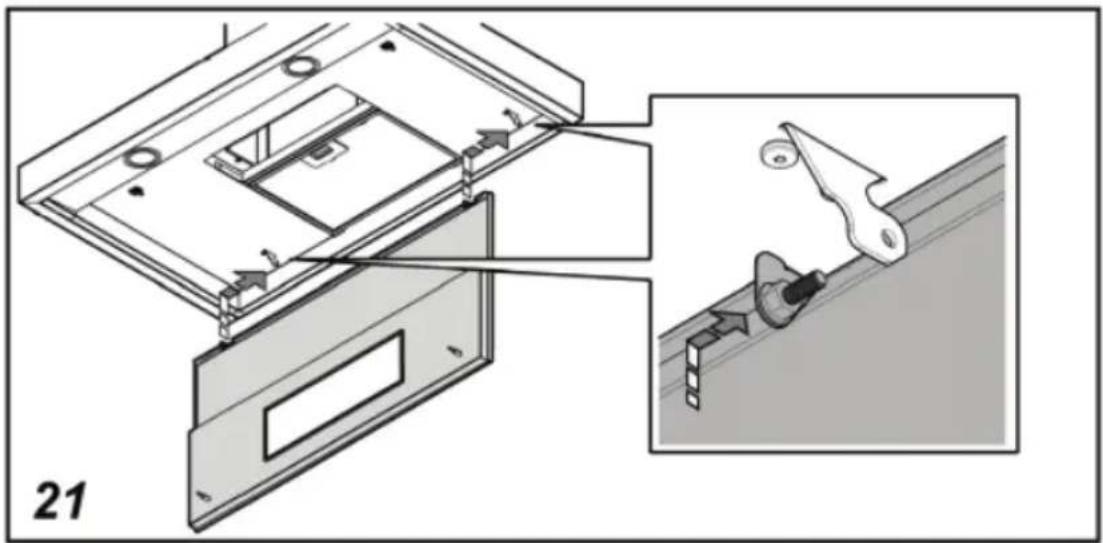
max 150 cm

natural_image
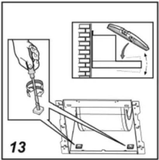
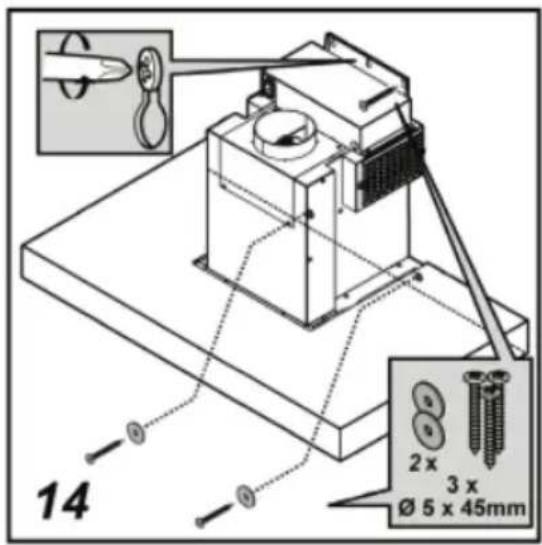
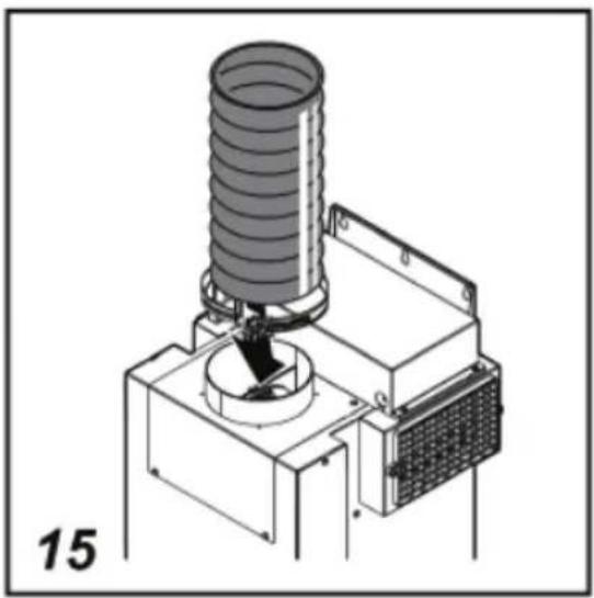
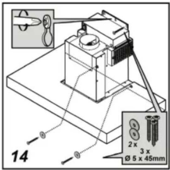
Diagram of a mechanical or electrical setup with a box, wires, and directional arrows (no text or symbols)Mounting the extractor hood



natural_image
Technical diagram of a mechanical assembly with a curved arrow indicating motion or force, no visible text or symbols
natural_image
Technical diagram of a mechanical assembly with an inset showing a rotating component (no text or symbols present)

natural_image
Isometric line drawing of a mechanical device with a curved arrow and label '11' (no text or symbols on the device itself)


natural_image
Technical illustration of a mechanical device with a cylindrical component mounted on a base, labeled '15' (no text or symbols on the diagram itself)
natural_image
Technical line drawing of a mechanical device with a coiled spring and control panel (no text or symbols)
natural_image
Isometric diagram of a mechanical device with a coiled spring and housing, showing motion arrows (no text or symbols)
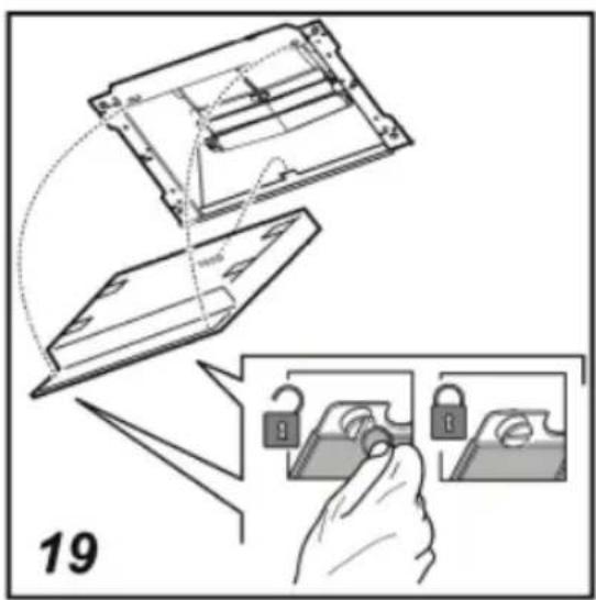


natural_image
Technical diagram showing a mechanical assembly with labeled parts and an inset view of a tool interacting with a component (no text or symbols present)
natural_image
Technical diagram showing a mechanical assembly with an inset view of a rotating component (no text or symbols present)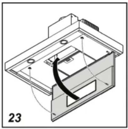
natural_image
Technical diagram of a device with internal components and a curved black line indicating a motion or assembly (no text or symbols present)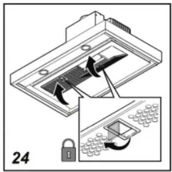
Disposal of packaging and appliance
In the manufacturing of this appliance durable materials were used. Make sure to dispose of this equipment responsibly at the end of its lifecycle. Ask the authorities for more information regarding this.
The appliance packaging is recyclable. The following may have been used:
- cardboard;
- polythene film (PE);
• CFC-free polystyrene (PS hard foam).
Dispose of these materials in a responsible manner and in accordance with government regulations.

natural_image
Symbol of a trash bin with crossed x's and no accompanying text or labelsAs a reminder of the need to dispose of household appliances separately, the product is marked with the symbol of a crossed-out wheeled dustbin. This means that at the end of its working life, the product must not be disposed of as urban waste. It must be taken to a special local authority differentiated waste collection centre or to a dealer providing this service.
Disposing of a household appliance separately avoids possible negative consequences for the environment and health deriving from inappropriate disposal and enables the constituent materials to be recovered to obtain significant savings in energy and resources.

- Algemeen
- Montage
- Généralités
- Allgemein
- Extraction system and electric flap
- Operation
- Maintenance
- Installation
- Environmental aspects
- Introduction
- Control panel
- Attention!
- Extraction systems
- These hoods have two extraction systems working parallel:
- Extractor hoods for mechanical ventilation systems
- Motorless extractor hoods
- Quiet, efficient and energy-saving
- Switching on/off
- Adjusting the speed
- Setting the switch-off time
- Switching the light on/off
- Grease filter signal
- Charcoal filter signal
- Cleaning
- Do not use alcohol!
- Cooker hood
- Stainless steel extractor hoods
- Metal grease filters
- Long life charcoal filter
- Removing the grease filters
- Removing the long life charcoal filter
- Important:
- Replacing the lights
- General
- Important to know:
- Electrical connection
- Attention:
- Disposal of packaging and appliance
Brand : Pelgrim
Model : CMV980RVS
Category : Range hood