
FL-36 R - External Flash OLYMPUS - Free user manual and instructions
Find the device manual for free FL-36 R OLYMPUS in PDF.
| Product Type | External flash for digital camera |
| Brand | OLYMPUS |
| Model | FL-36 R |
| Guide number (GN) | 36 (at 42 mm, Four Thirds) / 20 (at 12 mm) |
| Illumination angle | Automatic, from 12 mm to 42 mm (Four Thirds), with wide-angle panel up to 8 mm |
| Flash modes | TTL AUTO, AUTO, MANUAL, FP TTL AUTO, FP MANUAL, RC, SL AUTO, SL MANUAL |
| Power source | 2 AA batteries (alkaline, NiMH, lithium, oxyride, NiCd) or 1 CR-V3 pack (Olympus LB-01) |
| Dimensions | 67 x 108 x 95 mm (without protrusions) |
| Weight | 260 g (without batteries) |
| Recycling time | Approx. 7.5 s (alkaline batteries) to 6.5 s (lithium pack) |
| Number of flashes (full power) | Approx. 140 (alkaline batteries) to 320 (lithium pack) |
| Tilt angles | Up 0-90°, down 7°, right 0-90°, left 0-180° |
| Special functions | Wireless RC flash, slave flash, AF illuminator, exposure compensation +/-3 EV |
| Care and cleaning | Clean contacts with a dry cloth. Avoid dust and moisture. Do not use solvents. |
| Safety | Do not disassemble. Do not expose to water. Use only recommended batteries. Avoid firing within 1 m of eyes. |
| Spare parts and repairability | Contact Olympus support or an authorized center. No spare parts provided with the manual. |
Frequently Asked Questions - FL-36 R OLYMPUS
User questions about FL-36 R OLYMPUS
0 question about this device. Answer the ones you know or ask your own.
Ask a new question about this device
Download the instructions for your External Flash in PDF format for free! Find your manual FL-36 R - OLYMPUS and take your electronic device back in hand. On this page are published all the documents necessary for the use of your device. FL-36 R by OLYMPUS.
USER MANUAL FL-36 R OLYMPUS
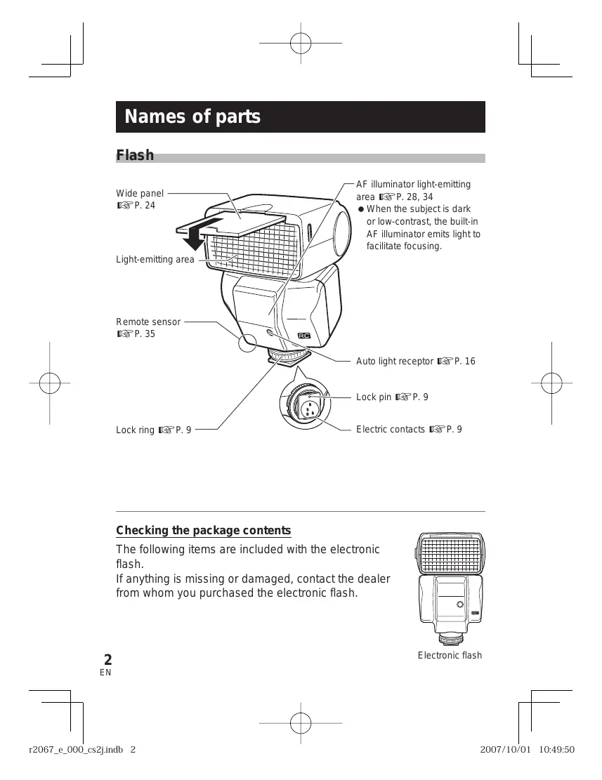
Checking the package contents
The following items are included with the electronic flash.
If anything is missing or damaged, contact the dealer from whom you purchased the electronic flash.
Electronic flash
Flash stand FLST-1
Flash case
- Instruction manual (this manual)
Warranty card
Notes on this manual
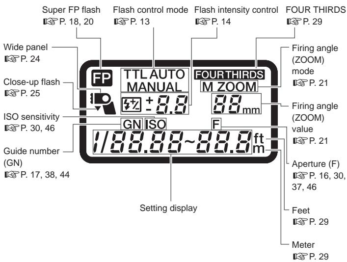
The indications on the control panel may differ from those shown in the illustration above depending on the setup of the electronic flash, the camera in use, and the shooting conditions.
For example, the firing angle (ZOOM) can be displayed in either of the following modes.
① FOUR THIRDS……Focal length of a Four Thirds System digital camera
(2) 135............ Focal length converted to an equivalent angle of view on a 135 type (35 mm film) camera
The text in this manual employs the [FOUR THIRDS] display mode and puts values in the [135] display mode inside parentheses, for example "(xx mm with the 135 type)".
For the selection of the display modes, refer to "Custom setup" (P. 28).
Table of contents
Names of parts 2
Flash 2
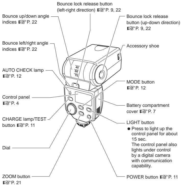
Control panel 4
Basic shooting. 7
Loading batteries 7
Attaching to the camera 9
Turning on the electronic flash 11
Shooting 12
Flash intensity control 14
Other flash photography modes 16
AUTO 16
MANUAL 17
FP TTL AUTO 18
FP MANUAL 20
Setting the firing angle (ZOOM) 21
Bounce shooting 22
Using the wide panel 24
Close-up flash 25
Various flash shooting methods 26
Custom setup 28
All reset. 31
Wireless flash 32
Basic wireless photography 33
About the placement of the electronic flash 35
Picture shooting using a digital camera without communication capability 37
AUTO 37
MANUAL 38
Slave flash 39
Warning display list. 40
Q&A 41
Guide number (GN) list. 44
Light control range in AUTO mode 46
Continuous firing. 47
Safety precautions
(Be sure to read and observe the following) 48
Caution for usage environment 52
Specifications 54
Basic shooting
Loading batteries
The batteries are available separately. Always use one of the following battery combinations.
- AA (R6) alkaline batteries/AA (R6) NiMH batteries/
AA (R6) lithium batteries/AA (R6) oxyride batteries/
AA (R6) NiCd batteries : × 2
- Lithium battery packs (CR-V3 type) (Olympus LB-01) : x 1
Notes
- AA (R6) manganese batteries cannot be used.
- Do not mix old and new batteries or batteries of different types together.
- Carry spare batteries when traveling or when using the electronic flash in cold areas.
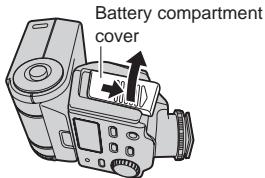
1 Open the battery compartment cover.
2 Insert the batteries with correct + / - polarity.
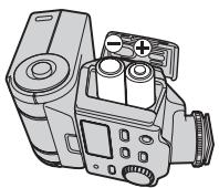
AA (R6) batteries
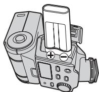
CR-V3
3 Close the battery compartment cover.
Flash interval and flash count
| Batteries used | Flash interval | Flash count |
| AA (R6) alkaline batteries | Approx. 7.5 sec. | Approx. 140 times |
| AA (R6) NiMH batteries (2,400 mAh) | Approx. 5.5 sec. | Approx. 200 times |
| AA (R6) lithium batteries | Approx. 7.5 sec. | Approx. 260 times |
| AA (R6) oxyride batteries | Approx. 6.5 sec. | Approx. 140 times |
| CR-V3 lithium battery pack | Approx. 6.5 sec. | Approx. 320 times |
- Measurements obtained from in-house tests at Olympus. Actual figures may vary depending on shooting conditions.
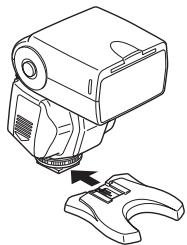
Attaching to the camera
Confirm that both the camera and electronic flash are off.
Attaching or removing the electronic flash while either the flash or the camera is on may result in malfunction.
1 Pressing the bounce lock release button, place the light-emitting section in standard position (horizontal, front).
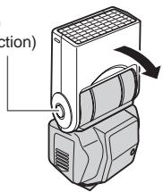
Bounce lock release button (up-down direction)
Hot shoe cover
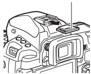
2 Remove the hot shoe cover from the camera.
- Store the hot shoe cover in the pocket located on the inner side of the flash case.
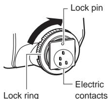
3 Loosen the lock ring.
- If the lock pin is protruding, pull it back inside by turning the lock ring as far as it will go in the direction opposite to LOCK.
Notes
- Do not apply excessive force to the lock pin.
- Do not touch the electric contacts with a finger or metallic object.
- Do not attach the electronic flash while the lock pin is protruding. Otherwise, malfunction may result.
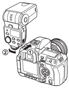
4 Slide the electronic flash all the way into the hot shoe until it stops with a click (1).
5 Turn the lock ring as far as it will go in the direction of LOCK (②).
How to remove
1 Loosen the lock ring completely, then slide the electronic flash out of the hot shoe.
2 Attach the hot shoe cover to the camera.
Using with a camera not equipped with hot shoe
- If the camera has an external flash connector, connect the electronic flash using the flash bracket and bracket cable (optional).
- The electronic flash can be used as a wireless flash with cameras compatible with the Olympus wireless RC flash system. "Wireless flash" (P.32)
- The electronic flash can be used as a slave flash with cameras equipped with the slave mode or manual flash mode. 忍 ^ 忍 "Slave flash" (P.39)
Turning on the electronic flash
Turn on the camera and electronic flash only after attaching to the camera. After turning on the electronic flash, be sure to check the remaining battery charge.
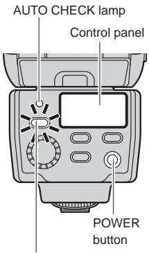
CHARGE lamp/TEST button
1 Press the POWER button.
- The control panel lights up and battery charging starts.
- Press the POWER button again to turn the electronic flash off.
2 Verify that the CHARGE lamp lights up.
- Replace the batteries if the time it takes for the CHARGE lamp to light up exceeds the following values.
| Alkaline or oxyride batteries | 30 sec. or more |
| NiMH or lithium batteries | 10 sec. or more |
- If the CHARGE lamp and AUTO CHECK lamp blink simultaneously, it means that the battery capacity is running low. In this case, replace the batteries.
- Press the TEST button to test the flash activation.
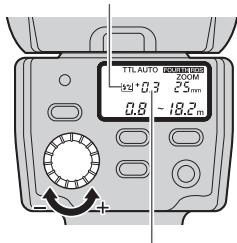
Shooting
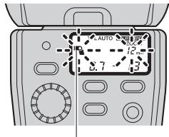
Let's try shooting pictures using the TTL AUTO mode. In TTL AUTO mode the flash intensity is controlled automatically according to the camera's settings.
Firing angle
Displayed according to the focal length of the lens.
1 Set the camera's shooting mode to P (Program Auto).
2 Press the MODE button of the electronic flash repeatedly to set the flash control mode to [TTL AUTO].
3 Press the shutter button halfway.
- Shooting information will be communicated between the camera and the electronic flash and the light control range will be displayed on the control panel.
- If the subject is not within the light control range, adjust the distance to the subject.
- The light control range will vary according to the camera's setup (ISO sensitivity, aperture value and focal length of the lens).
4 Press the shutter button fully.
- When flash activation has been performed correctly, the AUTO CHECK lamp blinks for about 5 seconds after the shutter is released.
Flash control modes
Select the flash control mode according to the subject and the shooting conditions. Press the MODE button repeatedly to change the flash control mode.
| Control panel display | Control operation | Main application | Ref. page |
| TTL AUTO | The flash light intensity is controlled automatically according to the camera's setup. The flash will be adjusted based on the brightness taken through the camera's lens. | Usually use this mode with a camera with communication capability. | P. 12 |
| AUTO | The flash light intensity is controlled automatically according to the camera's setup. The flash will be adjusted based on the brightness captured by auto light receptor on the electronic flash. | If the camera has communication capability, this mode can be used only when the camera is an AUTO-compatible model. | P. 16 |
| MANUAL | In this mode, the flash is emitted according to the guide number setting. | Shooting using manual flash. | P. 17 |
| FP TTL AUTO | Super FP flash. This mode allows you to use flash photography even at shutter speeds faster than the flash synchronization speed of the camera. In AUTO mode the flash light intensity is controlled automatically. In MANUAL mode the flash is emitted according to the guide number selected. | Outdoor shooting using flash, such as fill-in flash shooting in the daytime. | P. 18, 20 |
| FP MANUAL |
Notes
- Certain modes may be unavailable depending on the shooting mode set on the camera and the functions of the camera in use.
It is not possible to select an unavailable mode.
Operation of the flash in each shooting mode
Values and operation details in the table will vary depending on the camera. Refer to your camera's instruction manual.
| Shooting mode | Flash emission | Shutter speed | Aperture |
| P | The flash is emitted automatically when either backlight or a brightness level requiring flash is detected. | The camera sets the shutter speed automatically. At the shooting conditions that will trigger a flash emission, shutter speed is fixed at 1/30 or 1/60. | The camera sets the aperture automatically. |
| A | The camera sets the shutter speed automatically. At the shooting conditions that will require slower shutter speeds, shutter speed is fixed at 1/30 or 1/60. | The aperture will be set to the value you select. Use the guide number and the light control range as a reference when setting the aperture value. ↓“Guide number (GN) list” (P. 44), “Light control range in AUTO mode” (P. 46) | |
| S | The flash will always be emitted at shutter speeds slower than the flash synchronization speed of the camera. The flash will always be emitted with Super FP flash. | The shutter speed will be set to the value you select. | The camera sets the aperture automatically. |
| M | The aperture will be adjusted to the value you select. |
Flash intensity control
The flash light intensity can be adjusted between +3 and -3 .
1 In the custom setup, set the flash intensity control to [on]. "Custom setup" (P. 28)
The indicator appears in the control panel.
Flash intensity control
Flash intensity value
2 Turn the dial to select a flash intensity value.
- Turning the dial toward + will change the value as follows: 0 +0.3 +0.7 +1.0 +3.0 .
- Turning the dial toward - will change the value as follows: 0 -0.3 -0.7 -1.0 -3.0 .
3 When the camera's flash intensity control mode is set, the actual flash light intensity will be the total of the flash intensity value set on the electronic flash and that set on the camera.
The flash intensity value displayed on the control panel is that of the electronic flash only.
e.g.)
| Selected adjustment value | Adjustment value displayed on the control panel | Actual flash intensity value | |
| Flash | +0.3 | +0.3 | +0.6 |
| Camera | +0.3 |
Notes
- In MANUAL and FP MANUAL mode settings on the camera will be ignored.
Other flash photography modes
AUTO
The flash light intensity is controlled automatically by measuring the amount of light through the auto light receptor. This mode uses the settings on the camera together with the settings on the electronic flash.
1 The control panel shows the light control range according to the camera's setup.
- The light control range is not displayed if the camera's setup (ISO sensitivity and aperture value) does not match one of the usable ISO sensitivity/aperture value combinations. In this case, the [ISO] and [F] indicators blink to alert you. Change the camera's setup (ISO sensitivity and/or aperture value). "Light control range in AUTO mode" (P. 46)
2 When flash activation has been performed correctly, the AUTO CHECK lamp blinks for about 5 seconds after the shutter is released.
Test flash activation
Flash activation can be tested before actually releasing the shutter.
Press the TEST button for test flash activation.
If the AUTO CHECK lamp blinks for about 5 seconds after the test flash activation, the flash is adjusted correctly.
If the lamp does not blink, change the aperture value, ISO sensitivity, subject distance, etc.
- Checking the light by means of test flash activation is possible only in AUTO mode.
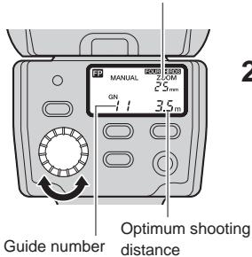
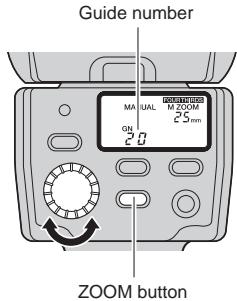
In this mode, the flash is emitted according to the guide number (GN) setting.
Firing angle
Displayed according to the focal length of the lens.
Guide number
Optimum shooting
distance
1 Turn the dial to set the guide number.
- The control panel shows the guide number set and the optimum shooting distance according to the camera's setup.
2 If the distance to the subject does not match the optimum shooting distance, change the guide number or the distance to the subject.
- The optimum shooting distance varies according to the camera's setup (ISO sensitivity, aperture value, lens focal distance and shutter speed). For details refer to "Guide number (GN) list" (P. 44).
Optimum shooting distance
When the ISO sensitivity is set to 100, you can calculate the optimum shooting distance by dividing the guide number (GN) by the aperture value (F). "Guide number (GN) list" (P. 44)
FP TTL AUTO
In this mode, the electronic flash uses Super FP flash to synchronize with high shutter speeds.
The following operations are possible using Super FP flash.
- Attenuation of shades when shooting a backlit picture.
- Outdoor portrait shooting using daytime fill-in flash shooting with the aperture opened up to blur the background.
Shooting against light

Without flash

With flash (FP TTL AUTO)
Portrait shooting

With aperture adjusted

With aperture open
1 The control panel shows the light control range according to the camera's setup.
2 Confirm that the distance to the subject is within the light control range.
- If it is not within the light control range, change the distance to the subject or the camera's setup.
- The light control range varies according to the camera's setup (ISO sensitivity, aperture value, lens focal length and shutter speed).
3 When flash activation has been performed correctly, the AUTO CHECK lamp blinks for about 5 seconds after the shutter is released.
Notes
- With Super FP flash the highest guide number will be lower than in TTL AUTO mode. As a result, the light control range will be shortened.
In this mode, Super FP flash is performed at the set flash intensity.
Firing angle
Displayed according to the focal length of the lens.
1 Turn the dial to set the guide number.
- The control panel shows the guide number set and the optimum shooting distance according to the camera's setup.
2 If the distance to the subject does not match the optimum shooting distance, change the settings or the distance to the subject.
- The optimum shooting distance varies according to the camera's setup (ISO sensitivity, aperture value, lens focal distance and shutter speed). For details refer to "Guide number (GN) list" (P. 44).
Optimum shooting distance
When the ISO sensitivity is set to 100, you can calculate the optimum shooting distance by dividing the guide number (GN) by the aperture value (F). "Guide number (GN) list" (P. 44)
Setting the firing angle (ZOOM)
The firing angle can be adjusted manually.
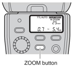
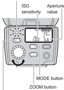
1 Press the ZOOM button to adjust the firing angle.
- The [M ZOOM] indicator lights in the control panel.
The firing angle can be set to one of 12, 14, 17, 25, 35 and 42mm (24, 28, 35, 50, 70 and 85mm with the 135 type).
Each press of the ZOOM button switches the firing angle as follows.
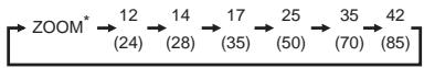
When the wide panel is used
"Using the wide panel" (P. 24):
- [ZOOM] (auto) can be selected only when the camera in use is equipped with the communication capability.
Notes
- Selecting a value larger than the focal length of the lens in use will darken the peripheral areas of the image.
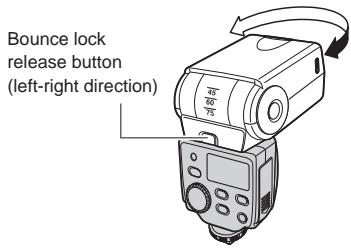
Bounce shooting
Bounce shooting refers to a method in which the light from the flash is bounced off the ceiling or walls.
This allows the light to go all around the subject, resulting in a soft picture without harsh contrast or shadow.

Shooting without bounce

Shooting with bounce
Bounce lock release button (left-right direction)
1 Pressing the bounce lock release button, turn the light-emitting section up/down and left/right.
You can turn it down: 7^ "Close-up flash" (P. 25)
Notes
- When the light-emitting section is at the bounce position, the light control range and optimum shooting distance are not displayed in the control panel.
- The color of the surface (ceiling and/or walls) off which the light is bounced will affect the pictures you take. Whenever possible, bounce the light off a neutral surface (white or very light grey will work best).
- The firing angle will be set automatically to 25mm (50 mm with the 135 type), and “- - ” will be displayed on the control panel. You can press the ZOOM button to adjust the firing angle manually. “Setting the firing angle (ZOOM)” (P. 21)
Using the reflector adapter (optional)
When you use an optional reflector adapter to shoot with bounce flash, you can divert part of the light toward the subject to reflect it off the subject. In this way you can achieve a catch-light effect — the light reflection on people's eyes. You can also illuminate with the reflector light parts of the picture that might have been shaded because of the bounce flash.
Shooting with bounce alone
Shooting with reflector adapter To achieve the catch-light effect, turn the light-emitting section directly up or directly sideways and aim the plate towards the subject.
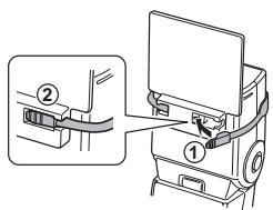
1 Pass the end with the mark of the reflector adapter's belt through the plate (①) and insert the part of the belt into the plate (②).
2 Align the flat surface of the plate with the electronic flash and wrap the belt around the flash (①). Insert the other end of the belt firmly into the plate (②).
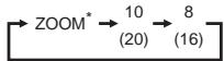
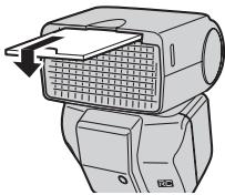
Using the wide panel
Use the built-in wide panel in flash shooting when the lens focal length is set to a position wider than 12mm .
Wide panel
ZOOM button
1 When the lens focal length is shorter than 12mm (24 mm with the 135 type), the wide panel warning indicator blinks in the control panel.
This does not occur if the camera is not equipped with communication capability.
2 Slide out the wide panel and place it on the light-emitting area.
The wide panel indicator lights up in the control panel.
3 Press the ZOOM button to adjust the firing angle.
- The firing angle can be selected from 8 mm and 10 mm (16 mm and 20 mm with the 135 type).
- When the wide panel is used, the guide number will be lower, and the available shooting range or the optimum shooting distance will be shortened.
Notes
- To prevent damage to the wide panel, do not flip it in the upward direction.
- If the wide panel is damaged when it is slid out, the ZOOM button will no longer be operable. If that happens, disable the wide panel switch to restore operability.
- "Custom setup" (P. 28)
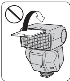
Close-up flash
When the distance to the subject is between 0.5m (1.6 ft.) and 1.0m (3.3 ft.), the flash light emission area will not match the range included in the shot. In this case, point the flash to the down-most angle (7^) using the bounce lock release button.
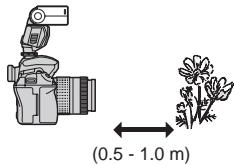
1 Pressing the bounce lock release button, tilt the light-emitting section to the down-most angle (7^) . The close-up flash indicator lights in the control panel.
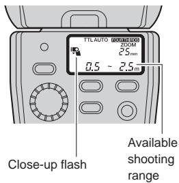
Notes
The available shooting range is up to 2.5m
- The flash light may be blocked when the lens is long or large in diameter. Be sure to perform test shooting.
- Do not use this function for any purpose other than close-up shooting. If it is used in normal shooting, there will be insufficient illumination for the upper half of the picture.
Various flash shooting methods
The following flash shooting methods are possible according to the camera's setup.
- Some flash shooting methods may be unavailable depending on the function and design of the camera.
- For details on how to use these modes, refer to the instruction manual for your camera.
Red-eye reduction flash
Reduces the appearance of red eyes due to flash emission.

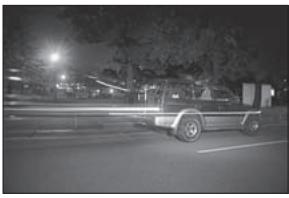
Slow synchronization
The flash is emitted while the shutter is open for a longer time. Usually when the flash is emitted, the shutter speed is fixed. However in this mode, the shutter speed is extended depending on the brightness. You will be able to take great pictures of people in night or twilight scenes.

Second curtain synchronization
A slow shutter is used and the flash is emitted immediately before the end of the exposure period.
This makes it possible to take pictures of moving objects such as car taillights with a streaming effect.
Combination with camera's built-in flash
When the camera in use has a built-in flash, it can be used simultaneously with the electronic flash.
- For example, you can bounce the light from the electronic flash off the wall or ceiling while using the camera's built-in flash for a catchlight effect. Advanced shooting techniques are possible.
- With certain camera models, the built-in flash may be disabled when the electronic flash is attached to the camera's hot shoe.

Notes
- The electronic flash control mode should be set to TTL AUTO or FP TTL AUTO.
Custom setup
Custom setup allows you to customize the electronic flash to suit your preferences.
MODE button
1 Press and hold the MODE button for more than 2 seconds, until the setup mode display appears in the control panel.
2 Press the MODE button to select the setup mode.
3 Turn the dial to select the value.
4 Press and hold the MODE button for more than 2 seconds to confirm the setup.
| Setup mode | Mode display | Value display | Function | Default value |
| MODE button | Dial | |||
| AF illuminator | ILL | R | AF illuminator is activated according to the control from the camera. | A |
| OFF | AF illuminator is off. | |||
| Flash cable | CLP | ON | Use this setting when not using the flash cable (attaching to the hot shoe or using a clip-on). | on |
| OFF | Use this setting when using the flash cable (off-flash cable). | |||
| Firing angle (ZOOM) display | FOUR THIRDS ZOOM - - mm | 4-3 | Firing angle is displayed in terms of the lens focal length of a FOUR THIRDS camera. | 4-3 |
| ZOOM - - mm | 135 | Firing angle is converted into the focal distance of the 135 type. This allows the flash to be used in the same feeling as the flash for a 135 type (35 mm film) camera. | ||
| Distance display unit | ft m | m | Distance is displayed in meter. | m |
| ft | Distance is displayed in feet. | |||
| Flash intensity control | #2 | OFF | Flash intensity cannot be adjusted. | OFF |
| ON | Flash intensity can be adjusted. | |||
| Wide panel switch disabling | # | ON | The wide panel switch is activated. Use this setting to detect that the wide panel has been slid out. | on |
| OFF | The wide panel switch is deactivated. Use this setting when the wide panel is damaged so as to be able to change the firing angle with the ZOOM button. | |||
| Guide number display | GN | ON | The flash intensity is displayed in a guide number. | on |
| OFF | The flash intensity is displayed in a flash intensity ratio. | |||
| ISO, F communication in AUTO mode • Available only in AUTO mode, with cameras with communication capability. | ISO F | ON | The ISO sensitivity and aperture value setup will be adjusted automatically by the camera. | on |
| OFF | You can adjust the ISO sensitivity and aperture value on the electronic flash. | |||
| ISO sensitivity selection in AUTO mode • Works with a camera without communication capability. Also works with a camera with communication capability when the ISO, F communication is set to [OFF]. | ISO | 25 3200 | The ISO sensitivity can be set with the dial. | 100 |
All reset
All reset resets the custom setups to the factory default settings.
1 Press the MODE and LIGHT buttons simultaneously for 2 or more seconds to reset to default settings.
- The distance display unit (m/ft) is not altered by the all reset operation.
Wireless flash
This flash is compatible with the Olympus wireless RC flash system. Using the electronic flash with an Olympus digital camera that is also compatible with this system, gives you wireless remote control over the flash emission. The flash mode and other controls are set on the camera and it controls the electronic flash automatically.
You can also combine several flashes to create a multiple flash array. To find out if your camera is compatible with this system, refer to the camera's instruction manual.
In wireless photography mode, the camera controls the electronic flash through a light communication system with the camera's built-in flash. Adjust the following settings on the camera and the electronic flash in advance.
RC mode:
This is the wireless mode. Set both the camera and the electronic flash to RC mode.
Channel:
Changes the channel so the camera will not receive mistaken signals from other Olympus wireless RC flash systems operating nearby. Select a channel between 1 and 4 and set the same channel on the camera and the electronic flash.
Group:
You can control remotely up to three groups (A, B, C) of flash arrays with different flash modes and other settings. On the electronic flash set in advance the group with which the flash will be emitted.
Basic wireless photography
This function will be explained using an example of the electronic flash used together with an Olympus digital SLR camera E-3. Refer to the camera's instruction manual for details on the setup range of flash and the operations on the camera.
1 Place the camera and the electronic flash. "About the placement of the electronic flash" (P. 35)
2 Press the MODE button of the electronic flash repeatedly to set the flash control mode to RC mode.
3 Set [RC MODE] on the camera to [ON] and set the camera's built-in flash to a condition that it can be emitted.
- Set the flash mode and the flash intensity on the camera.
![OLYMPUS FL-36 R - Set [RC MODE] on the camera to [ON] and set the camera's built-in flash to a condition that it can be emitted. - 1](/content/2025/01/125249/images/362230379cb53136681be6f00eddc05a3ed6d4c942ad9f654366e348ec615b13.jpg)
![OLYMPUS FL-36 R - Set [RC MODE] on the camera to [ON] and set the camera's built-in flash to a condition that it can be emitted. - 2](/content/2025/01/125249/images/b7f3b493b4c26f50e0622e94e7ad3d1f3f6c8aa0c0b9c0744e027e20211641d4.jpg)
MODE button
4 While holding down the MODE button, turn the dial to select the channel and group.
- When 2 seconds pass with the MODE button held, the camera enters custom setup.
5 After shooting preparations are completed, take some test shots to check the flash operation and images.
6 Begin shooting while checking the charging completed indications of the camera and the electronic flash.
- The charge condition of the electronic flash is not communicated to the camera. Shoot the picture only after checking that the CHARGE lamp at the back of the electronic flash is on, or that the AF illuminator part at the front of the electronic flash is blinking.
- When the camera's flash intensity control mode is set, the actual flash light intensity will be the total of the flash intensity value set on the electronic flash and that set on the camera.
Notes
- The firing angle of the flash cannot be controlled automatically so be sure to check it beforehand. Pressing the ZOOM button on the electronic flash once will display the firing angle for about 2 seconds. You can change the firing angle by pressing ZOOM button again while the current firing angle is displayed. Verify whether the firing angle setting is appropriate or not by performing a test shot.
- When shooting using 2nd curtain synchronization, set the shutter speed up to 4 seconds since the flash will be emitted automatically after about 5 seconds.
- In RC mode the built-in flash of the camera is used to send the remote control signal and therefore cannot be used as a flash.
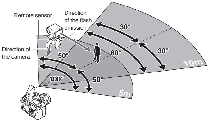
About the placement of the electronic flash
The remote control signal is sent using the built-in flash of the camera so the maximum range for the placement of the electronic flash will vary depending on the camera. For details, refer to the camera's instruction manual.
1 Attach the flash stand to the camera.
- Slide the electronic flash all the way into the flash stand until it stops with a click.
- If the lock pin is protruding, pull it back inside by turning the lock ring as far as it will go in the direction opposite to LOCK.
- You can also fix the flash stand on a tripod.
2 Place the electronic flash so that the remote sensor is facing the camera, and turn the light-emitting section in the direction of the subject you want to shoot.
Placement examples: Placement of a single flash
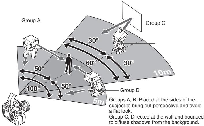
Changing the amount of light of each flash
When shooting with multiple flashes you can create different effects of the flash photography by changing the amount of light of each flash. First, try to change the flash mode and flash intensity value for each group. If that is not enough to create the expression you want, try the following.
- Change the distance between the electronic flash and the subject.
- Change the flash intensity value on the electronic flash.
- Change the firing angle.
Notes
- If there is an object between the camera's built-in flash and the electronic flash it may obstruct the light signal and the flash may not be emitted.
- If enough light can be reflected back from the subject or from the background (for example a wall when shooting indoors), the arrangement will work even if it is not perfectly aligned.
- Although there is no limit to the number of wireless flashes you can use, it is recommended that each group have no more than three flashes to prevent flash malfunction due to mutual interference.
- Place flashes that are to be emitted in AUTO mode so that the auto light receptor will face the subject. In such case, the remote sensor will not face the camera so the flash will be emitted making use to reflected light from the subject or background.
- After you finish placing the electronic flash, be sure to perform a test shot.
Picture shooting using a digital camera without communication capability
When using the electronic flash with a camera without communication capability, adjust the ISO sensitivity and aperture value in AUTO mode to the same values as on the camera or change the shooting distance in MANUAL mode.
You can also emit the flash wirelessly as a slave flash. "Slave flash" (P. 39)
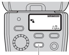
AUTO
In this mode, the flash light intensity is controlled automatically according to the aperture setting.
AUTO CHECK lamp
TEST button
1 While holding down the MODE button, turn the dial to adjust the ISO sensitivity.
- When 2 seconds pass with the MODE button held, the camera enters custom setup.
2 Press the ZOOM button to adjust the firing angle according to the focal distance of the lens.
3 Turn the dial according to the aperture value of the lens.
- If the ISO sensitivity/aperture value combinations do not match the usable range, the ISO sensitivity and aperture value blink to alert you. In this case, change the ISO sensitivity and/or aperture value. "Light control range in AUTO mode" (P. 46)
- Press the TEST button to test the flash activation. "Test flash activation" (P. 16)
4 When flash activation has been performed correctly, the AUTO CHECK lamp blinks for about 5 seconds after the shutter is released.
Flash intensity value
By selecting an ISO sensitivity and aperture value different from those set on the camera, the flash intensity can be adjusted in 1/3 steps.
MANUAL
In this mode, the flash is emitted according to the guide number (GN) setting.
1 The control panel shows the current guide number.
- Flash intensity can also be displayed as flash intensity ratio. "Custom setup" (P. 28)
- Flash intensity ratio: Ratio of emitted flash intensity with respect to the intensity at full emission.
2 Press the ZOOM button to adjust the firing angle according to the focal distance of the lens.
3 Turn the dial to set the guide number.
How to determine the aperture value and guide number
When the shooting distance and aperture value are already determined:
Determine the guide number with the following formula and set the value on the electronic flash.
$$ \text {G u i d e n u m b e r (G N)} = \frac {\text {A p e r t u r e v a l u e (F) x S h o o t i n g d i s t a n c e (m)}}{\text {I S O s e n s i t i v i t y c o e f f i c i e n t s}} $$
When it is necessary to determine the aperture value:
Determine the aperture value with the following formula and set the value on the electronic flash.
$$ \text {A p e r t u r e} (F) = \frac {\text {G u i d e n u m b e r (G N)} \times \text {I S O s e n s i t y c o e f f i c i e n t}}{\text {S h o o t i n g d i s t a n c e (m)}} $$
When it is necessary to determine the optimum shooting distance:
$$ \text {O p t i m u m} (m) = \frac {\text {G u i d e n u m b e r (G N)} \times \text {I S O s e n s i t y c o e f f i c i e n t}}{\text {A p e r t u r e v a l u e (F)}} $$
ISO sensitivity and their coefficients
| ISO sensitivity | 25 | 50 | 100 | 200 | 400 | 800 | 1600 | 3200 |
| Coefficient | 0.5 | 0.71 | 1.0 | 1.4 | 2.0 | 2.8 | 4.0 | 5.6 |
Slave flash
The electronic flash is equipped with the slave function. In this function you can emit the flash with a wireless remote control by synchronizing it to the emission of another flash.
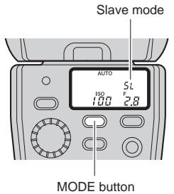
1 Place the electronic flash.
Refer to "About the placement of the electronic flash" (P. 35).
2 Press the MODE button of the electronic flash repeatedly to set the flash control mode to [SL AUTO] or [SL MANUAL].
The flash setup is the same as in AUTO or MANUAL mode. "AUTO" (P. 37), "MANUAL" (P. 38)
3 Setup the camera in the following way.
- Set cameras with slave mode to slave mode.
- Set cameras with manual flash emission mode to manual flash mode. This setup will function also if you attach an external flash with manual flash emission mode to the camera.
Notes
- The slave flash mode cannot be used with cameras that perform a pre-flash because the electronic flash will be emitted simultaneously with the pre-flash.
- If other photographers are shooting using flash, the electronic flash may react to those lights and be emitted.
- The firing angle of the flash cannot be controlled automatically so be sure to check it beforehand. Pressing the ZOOM button on the electronic flash once will display the firing angle for about 2 seconds. You can change the firing angle by pressing ZOOM again while the current firing angle is displayed. Verify whether the firing angle setting is appropriate or not by performing a test shot.
Warning display list
| Warning details | Control panel display | Remedy | Ref. page |
| In AUTO mode: Out of light control range | AUTO GOGO DODD ZOOM (camera with communication capability) | Change the camera's ISO sensitivity or aperture setting. | P. 16 |
| AUTO GOGO DODD ZOOM (camera without communication capability) | P. 37 | ||
| In MANUAL mode: Subject too close | MANUAL GOGO DODD M ZOOM GN 40 7.5cm | When the optimum shooting distance is less than 0.6 m (1.9 ft.) (0.5 m (1.6 ft.) in case of close-up flash), the displayed value blinks to alert you that the shooting range does not match the light emission area of the flash. ① Change the camera's ISO sensitivity or aperture setting. ② Change the guide number setting. | P. 17 |
| In FP MANUAL mode: Subject too close | MANUAL GOGO DODD ZOOM GN 40 7.5cm | ① Change the camera's ISO sensitivity or aperture setting. ② Change the guide number setting. | P. 20 |
| In all modes: Wide panel request warning | SET the wide panel. | Set the wide panel. | P. 24 |
| In all modes: Downward bounce | The light-emitting section is tilted 7° downwards. Cancel this setting except for close-up flash photography. | P. 25 | |
| In all modes: Wide panel warning | The wide panel is set. Pay attention to the distance to the subject since the guide number will be lower. | P. 24 |
Q&A
Q When are test flash activation and auto checking effective?
A Checking the optimum flash activation based on the AUTO CHECK lamp is particularly effective in bounce flash (in AUTO modes only).
Q Why does the electronic flash get hot after successive emissions?
A The batteries generate heat when flash is emitted repeatedly. In this case, use the electronic flash at intervals until the flash emission section and batteries cool down.
Why can't I mount the electronic flash on the camera?
A The electronic flash cannot be attached if the lock pin is protruding. In such case, turn the lock ring as far as it will go in the direction opposite to LOCK (P. 9).
Q Why doesn't the flash control mode change when I press the MODE button?
A When the electronic flash is connected to certain types of communication-capable cameras, the flash control mode can only be controlled from the camera.
Q What is the recommended white balance setting for the camera when using the electronic flash?
A The auto white balance mode is recommended. If you use the manual white balance mode, set the color temperature to around 5500K. Note that the color temperature varies depending on the flash intensity.
Q The AF illuminator does not light up. What is wrong?
A The AF illuminator only works when you use the electronic flash with Olympus Four Thirds System digital SLR cameras. It does not work with other cameras. The AF illuminator will not work also when lenses large in diameter that can obstruct it are attached to the camera.
Q The light control range is not displayed on the control panel. What is wrong?
A The light control range is not displayed in the following cases:
- When the extension tube EX-25 (optional) is used.
- When the lens has been removed.
In bounce shooting. - When the ISO sensitivity and aperture value are out of the setting range.
Q The flash wasn't emitted when shooting in RC mode. What is wrong?
A Verify that the camera and the electronic flash are set to the same channel and that the group is set correctly (P. 34).
Q How can I find out if my camera is compatible with wireless flash?
A You can use the RC mode only with cameras compatible with the Olympus wireless RC flash system. With other cameras you may be able to use the electronic flash as slave flash if the camera's built-in flash can be set to slave flash mode or manual flash mode. For details, refer to the camera's instruction manual.
Q When the Olympus digital camera entered the sleep mode, the control panel on the electronic flash turned off as well. Is this normal?
A Yes, it is normal. When the camera enters the sleep mode, the FL-36R does as well. When the camera wakes up, so does the FL-36R. After approximately 15 minutes in sleep mode, the FL-36R turns off. In such a case, press the POWER button to turn the FL-36R back on.
Q Does the FL-36R also turn off when the Olympus digital camera is turned off?
A When the camera is turned off, the FL-36R enters the sleep mode. After approximately 15 minutes, the FL-36R automatically turns off. In such a case, press the POWER button to turn the FL-36R back on.
Q Why did the FL-36R automatically turn off?
A The FL-36R automatically turns off in RC mode and slave mode when no operations are performed for 60 minutes. When connected to a camera without communication capability, the FL-36R enters the sleep mode if it is not operated for about 15 minutes. After another 15 minutes, the power turns off.
Guide number (GN) list
- TTL AUTO/AUTO
ISO100,m
| ZOOM (mm) | FOUR THIRDS | 8 | 10 | 12 | 14 | 17 | 25 | 35 | 42 |
| With 135 | 16 | 20 | 24 | 28 | 35 | 50 | 70 | 85 | |
| TTL AUTO/AUTO | Full emission | 12 | 14 | 20 | 22 | 24 | 28 | 32 | 36 |
- MANUAL
ISO100,m
| ZOOM (mm) | FOUR THIRDS | 8 | 10 | 12 | 14 | 17 | 25 | 35 | 42 |
| With 135 | 16 | 20 | 24 | 28 | 35 | 50 | 70 | 85 | |
| MANUAL | 1/1 | 12.0 | 14.0 | 20.0 | 22.0 | 24.0 | 28.0 | 32.0 | 36.0 |
| 1/2 | 8.5 | 9.9 | 14.1 | 15.6 | 17.0 | 19.8 | 22.6 | 25.5 | |
| 1/4 | 6.0 | 7.0 | 10.0 | 11.0 | 12.0 | 14.0 | 16.0 | 18.0 | |
| 1/8 | 4.2 | 4.9 | 7.1 | 7.8 | 8.5 | 9.9 | 11.3 | 12.7 | |
| 1/16 | 3.0 | 3.5 | 5.0 | 5.5 | 6.0 | 7.0 | 8.0 | 9.0 | |
| 1/32 | 2.1 | 2.5 | 3.5 | 3.9 | 4.2 | 4.9 | 5.7 | 6.4 | |
| 1/64 | 1.5 | 1.8 | 2.5 | 2.8 | 3.0 | 3.5 | 4.0 | 4.5 | |
| 1/128 | 1.1 | 1.2 | 1.8 | 1.9 | 2.1 | 2.5 | 2.8 | 3.2 |
FP TTL AUTO
ISO100,m
| ZOOM (mm) | FOUR THIRDS | 8 | 10 | 12 | 14 | 17 | 25 | 35 | 42 |
| With 135 | 16 | 20 | 24 | 28 | 35 | 50 | 70 | 85 | |
| Shutter speed | 1/125 | 8.5 | 9.9 | 14.1 | 15.6 | 17.0 | 19.8 | 22.6 | 25.5 |
| 1/160 | 7.5 | 8.8 | 12.5 | 13.8 | 15.0 | 17.5 | 20.0 | 22.5 | |
| 1/200 | 6.7 | 7.8 | 11.2 | 12.3 | 13.4 | 15.7 | 17.9 | 20.1 | |
| 1/250 | 6.0 | 7.0 | 10.0 | 11.0 | 12.0 | 14.0 | 16.0 | 18.0 | |
| 1/320 | 5.3 | 6.2 | 8.8 | 9.7 | 10.6 | 12.4 | 14.1 | 15.9 | |
| 1/400 | 4.7 | 5.5 | 7.9 | 8.7 | 9.5 | 11.1 | 12.6 | 14.2 | |
| 1/500 | 4.2 | 4.9 | 7.1 | 7.8 | 8.5 | 9.9 | 11.3 | 12.7 | |
| 1/640 | 3.8 | 4.4 | 6.3 | 6.9 | 7.5 | 8.8 | 10.0 | 11.3 | |
| 1/800 | 3.4 | 3.9 | 5.6 | 6.1 | 6.7 | 7.8 | 8.9 | 10.1 | |
| 1/1000 | 3.0 | 3.5 | 5.0 | 5.5 | 6.0 | 7.0 | 8.0 | 9.0 | |
| 1/1250 | 2.7 | 3.1 | 4.5 | 4.9 | 5.4 | 6.3 | 7.2 | 8.0 | |
| 1/1600 | 2.4 | 2.8 | 4.0 | 4.3 | 4.7 | 5.5 | 6.3 | 7.1 | |
| 1/2000 | 2.1 | 2.5 | 3.5 | 3.9 | 4.2 | 4.9 | 5.7 | 6.4 | |
| 1/2500 | 1.9 | 2.2 | 3.2 | 3.5 | 3.8 | 4.4 | 5.1 | 5.7 | |
| 1/3200 | 1.7 | 2.0 | 2.8 | 3.1 | 3.4 | 3.9 | 4.5 | 5.0 | |
| 1/4000 | 1.5 | 1.8 | 2.5 | 2.8 | 3.0 | 3.5 | 4.0 | 4.5 | |
| 1/5000 | 1.3 | 1.6 | 2.2 | 2.5 | 2.7 | 3.1 | 3.6 | 4.0 | |
| 1/6400 | 1.2 | 1.4 | 2.0 | 2.2 | 2.4 | 2.8 | 3.2 | 3.6 | |
| 1/8000 | 1.1 | 1.2 | 1.8 | 1.9 | 2.1 | 2.5 | 2.8 | 3.2 |
- FP MANUAL
The following guide number figures have a 1/1 flash intensity ratio.
ISO100,m
| ZOOM (mm) | FOUR THIRDS | 8 | 10 | 12 | 14 | 17 | 25 | 35 | 42 |
| With 135 | 16 | 20 | 24 | 28 | 35 | 50 | 70 | 85 | |
| Shutter speed | 1/125 | 8.5 | 9.9 | 14.1 | 15.6 | 17.0 | 19.8 | 22.6 | 25.5 |
| 1/160 | 7.5 | 8.8 | 12.5 | 13.8 | 15.0 | 17.5 | 20.0 | 22.5 | |
| 1/200 | 6.7 | 7.8 | 11.2 | 12.3 | 13.4 | 15.7 | 17.9 | 20.1 | |
| 1/250 | 6.0 | 7.0 | 10.0 | 11.0 | 12.0 | 14.0 | 16.0 | 18.0 | |
| 1/320 | 5.3 | 6.2 | 8.8 | 9.7 | 10.6 | 12.4 | 14.1 | 15.9 | |
| 1/400 | 4.7 | 5.5 | 7.9 | 8.7 | 9.5 | 11.1 | 12.6 | 14.2 | |
| 1/500 | 4.2 | 4.9 | 7.1 | 7.8 | 8.5 | 9.9 | 11.3 | 12.7 | |
| 1/640 | 3.8 | 4.4 | 6.3 | 6.9 | 7.5 | 8.8 | 10.0 | 11.3 | |
| 1/800 | 3.4 | 3.9 | 5.6 | 6.1 | 6.7 | 7.8 | 8.9 | 10.1 | |
| 1/1000 | 3.0 | 3.5 | 5.0 | 5.5 | 6.0 | 7.0 | 8.0 | 9.0 | |
| 1/1250 | 2.7 | 3.1 | 4.5 | 4.9 | 5.4 | 6.3 | 7.2 | 8.0 | |
| 1/1600 | 2.4 | 2.8 | 4.0 | 4.3 | 4.7 | 5.5 | 6.3 | 7.1 | |
| 1/2000 | 2.1 | 2.5 | 3.5 | 3.9 | 4.2 | 4.9 | 5.7 | 6.4 | |
| 1/2500 | 1.9 | 2.2 | 3.2 | 3.5 | 3.8 | 4.4 | 5.1 | 5.7 | |
| 1/3200 | 1.7 | 2.0 | 2.8 | 3.1 | 3.4 | 3.9 | 4.5 | 5.0 | |
| 1/4000 | 1.5 | 1.8 | 2.5 | 2.8 | 3.0 | 3.5 | 4.0 | 4.5 | |
| 1/5000 | 1.3 | 1.6 | 2.2 | 2.5 | 2.7 | 3.1 | 3.6 | 4.0 | |
| 1/6400 | 1.2 | 1.4 | 2.0 | 2.2 | 2.4 | 2.8 | 3.2 | 3.6 | |
| 1/8000 | 1.1 | 1.2 | 1.8 | 1.9 | 2.1 | 2.5 | 2.8 | 3.2 |
The guide numbers for flash intensity ratios other than 1/1 in the FP MANUAL mode can be calculated with the following formula.
Guide number = Guide number at 1 / 1× Flash intensity ratio coefficient
Flash intensity ratios and their coefficients
| Flash intensity ratio | 1/1 | 1/2 | 1/4 | 1/8 | 1/16 |
| Coefficient | 1.0 | 0.71 | 0.5 | 0.35 | 0.25 |
Light control range in AUTO mode
Useable ISO sensitivity/aperture value (F) combinations for light control in AUTO mode
AUTO light control range (m)
| Aperture value | ISO sensitivity | Firing angle (mm) Upper row: FOUR THIRDS Lower row: 135 | |||||||||||||
| 3200 | 1600 | 800 | 400 | 200 | 100 | 50 | 8(W panel) | 10(W panel) | 12 | 14 | 17 | 25 | 35 | 42 | |
| 16(W panel) | 20(W panel) | 24 | 28 | 35 | 50 | 70 | 85 | ||||||||
| F8 | F5.6 | F4 | F2.8 | F2 | F1.4 | 0.8 - 8.6 | 0.9 - 10.0 | 1.3 - 14.3 | 1.4 - 15.7 | 1.5 - 17.1 | 1.8 - 20.0 | 2.0 - 22.9 | 2.3 - 25.7 | ||
| F11 | F8 | F5.6 | F4 | F2.8 | F2 | F1.4 | 0.6 - 6.0 | 0.6 - 7.0 | 0.9 - 10.0 | 1.0 - 11.0 | 1.1 - 12.0 | 1.3 - 14.0 | 1.4 - 16.0 | 1.6 - 18.0 | |
| F16 | F11 | F8 | F5.6 | F4 | F2.8 | F2 | 0.5 - 4.3 | 0.5 - 5.0 | 0.6 - 7.1 | 0.7 - 7.9 | 0.8 - 8.6 | 0.9 - 10.0 | 1.0 - 11.4 | 1.1 - 12.9 | |
| F22 | F16 | F11 | F8 | F5.6 | F4 | F2.8 | 0.5 - 3.0 | 0.5 - 3.5 | 0.5 - 5.0 | 0.5 - 5.5 | 0.5 - 6.0 | 0.6 - 7.0 | 0.7 - 8.0 | 0.8 - 9.0 | |
| F32 | F22 | F16 | F11 | F8 | F5.6 | F4 | 0.5 - 2.1 | 0.5 - 2.5 | 0.5 - 3.6 | 0.5 - 3.9 | 0.5 - 4.3 | 0.5 - 5.0 | 0.5 - 5.7 | 0.6 - 6.4 | |
| F32 | F22 | F16 | F11 | F8 | F5.6 | 0.5 - 1.5 | 0.5 - 1.8 | 0.5 - 2.5 | 0.5 - 2.8 | 0.5 - 3.0 | 0.5 - 3.5 | 0.5 - 4.0 | 0.5 - 4.5 | ||
| F32 | F22 | F16 | F11 | F8 | 0.5 - 1.1 | 0.5 - 1.3 | 0.5 - 1.8 | 0.5 - 2.0 | 0.5 - 2.2 | 0.5 - 2.5 | 0.5 - 2.9 | 0.5 - 3.3 | |||
| F32 | F22 | F16 | F11 | 0.5 - 0.8 | 0.5 - 0.9 | 0.5 - 1.3 | 0.5 - 1.4 | 0.5 - 1.5 | 0.5 - 1.8 | 0.5 - 2.0 | 0.5 - 2.3 | ||||
| F32 | F22 | F16 | 0.5 - 0.5 | 0.5 - 0.6 | 0.5 - 0.9 | 0.5 - 1.0 | 0.5 - 1.1 | 0.5 - 1.3 | 0.5 - 1.5 | 0.5 - 1.6 | |||||
The right part of the table shows light control ranges when using a camera without communication capability. The figures given are for reference only.
When you use a camera equipped with the communication function, the light metering range for the lens in use is displayed on the control panel. This range may be different from the figures in this table.
Continuous firing
For your safety, be sure to observe the following.
Continuous firings make the light-emitting section hot and may result in its deterioration, malfunction or deformation. Therefore, continuous firing should be limited to the counts shown in the following table. Always leave the electronic flash unused for at least 10 minutes after continuous firing up to the limit count.
Limit counts of continuous firings
| Flash intensity | Flash interval | Limit count |
| FULL; 1/1 | 6 sec. | 10 |
| 1/2 | 3 sec. | 20 |
| 1/4 | 1 sec. | 40 |
| 1/8 - 1/128 | 0.5 sec. or less | 80 |
Safety precautions (Be sure to read and observe the following)
This instruction manual uses a variety of common symbols and icons to assist you in proper handling and usage of this product and to warn you of potential hazards to yourself and others as well as to property. These symbols and their significance are described below.
| Symbols for prohibiting action | Symbol instructing action |
| Prohibited Disassembly prohibited | Mandatory |
This electronic flash has been designed exclusively for use with Olympus digital cameras. Do not connect the electronic flash to a camera not manufactured by Olympus, as this may result in a malfunction or damage to the camera and/or flash.
DANGER


The electronic flash incorporates high-voltage circuitry. Never attempt to disassemble or modify it, as this may result in electric shock and/or injury.
Do not use the electronic flash in a place where it may be exposed to flammable or explosive gas. Otherwise, fire ignition or explosion may result.
To prevent a traffic accident, do not direct the flash towards the driver of a car.
WARNING
- Do not fire the flash or AF illuminator light immediately in front of a person's eyes (particularly an infant). Exposure to the light from the flash at a very short range may cause irreparable injury to the eyes. Be especially careful to avoid using the electronic flash at a distance of less than 1 meter from an infant.
Do not leave the electronic flash and batteries within reach of children. - If a child swallows a battery or small accessory, see a doctor immediately.
- If the flash is emitted near a child, their eyes may be injured irreparably.
- Moving parts of the electronic flash could injure a child.
Avoid the following actions to prevent fire or injury due to battery fluid leak, overheating, fire ignition or bursting. - Do not use batteries that are not specified for use with this electronic flash.
- Do not throw the battery in a fire, expose it to heat, short-circuit it, or disassemble it.
- Do not mix old and new batteries, or batteries of different types or brands.
- Do not attempt to recharge non-rechargeable batteries such as alkaline batteries.
- Do not load batteries with the +/- polarity reversed.
- Do not store the electronic flash in a place exposed to excessive dust or moisture. Otherwise, fire or electric shock may result.
- Do not use the flash when it is covered by a flammable object such as a handkerchief.
- Do not touch the light-emitting area after use. It will be very hot and could burn you.
If the electronic flash is dropped in water or any fluid gets inside, immediately remove the batteries. Contact your dealer or consult your Olympus Authorized Service Station. Continued use could result in fire or electric shock.
Do not expose the electric flash to dripping or splashing.
Do not expose the battery to excessive heat such as sunshine, fire or the like.


CAUTION
If you notice any abnormalities such as leakage, discoloration, deformation, overheating, or odor, stop using this device. Continued use could result in fire, overheating or explosion. Remove the batteries carefully to avoid burning yourself and to prevent exposure to gas or dangerous fluids that may be released. Contact your dealer or consult your Olympus Authorized Service Station.
Always remove the batteries when you don't expect to use the electronic flash for a long period. Otherwise, heat generation or fluid leak from the batteries may result in fire, injury and/or contamination of the surroundings.
- Do not use a leaking battery. Doing so could result in fire or electric shock.
Do not handle the electronic flash with wet hands. Doing so could result in electric shock.
- Do not leave the electronic flash in a place where it may be exposed to high temperatures. Otherwise, deterioration of parts or fire may result.
- Do not take out the batteries immediately after using the electronic flash continuously for a long period. Otherwise, the hot batteries may cause burns.
- Do not deform the battery compartment or allow any foreign objects to get inside.


BATTERY PRECAUTIONS
Use only the specified batteries.
■ Be sure to observe the following points. Otherwise, battery fluid leak, overheating, fire ignition and/or bursting may result.
- Do not mix old and new batteries, recharged and discharged batteries, batteries of different capacities, or batteries of different types or brands.
- Do not attempt to recharge non-rechargeable batteries such as alkaline batteries.
- Do not load or use the batteries with the +/- polarity reversed. If the batteries do not fit smoothly in the battery compartment, do not force them.
- Never use a battery if its outer coating (insulation) has been partially or entirely peeled off. Otherwise, leakage, overheating or explosion may result.
- Some brand-new batteries may also have their outer coating (insulation) peeled off completely or partially. Never use these batteries.
Do not use the following kinds of batteries.


Outer coating (insulation) is peeling or has peeled off (even if the battery is brand-new).

The negative end is slightly swollen and is not covered by the coating (insulation).

The negative end is flat (whether or not a part of the negative pole is covered by the coating).
If battery fluid gets on your skin or clothes, it may irritate your skin. Immediately rinse your skin or clothes with clean water.
If battery fluid comes in contact with your eyes, blindness may result. Rinse your eyes with clean water without rubbing them and see a doctor immediately.
Do not apply a strong shock to a battery or throw it.
- Do not immerse batteries in water or expose to moisture including rain, seawater and animal urine.
Do not throw a battery in fire or heat it.


Caution for usage environment
-
To protect the high-precision technology contained in this product, never leave the flash in the places listed below, no matter if in use or storage:
-
Places where temperatures and/or humidity are high or go through extreme changes. Direct sunlight, beaches, locked cars, or near other heat sources (stove, radiator, etc.) or humidifiers.
- In sandy or dusty environments.
- Near flammable items or explosives.
- In wet places, such as bathrooms or in the rain.
-
In places prone to strong vibrations.
-
Never drop the flash or subject it to severe shocks or vibrations.
- When the electronic flash has not been used for a long period, mold or moss may form. This can cause a malfunction. To prevent this, it is recommended to check the operations before using the electronic flash after a long period of storage.
- Do not touch electric contacts on the flash.
Battery Handling Precautions
- If the + / - terminals of a battery are stained with sweat or oil smudges, contact failure may result. Clean the terminals well with a dry cloth before using the batteries.
- All rechargeable batteries must be recharged using the specified battery charger, simultaneously and completely. Be sure to read the battery and battery charger instruction manual.
- In general, battery performance will be temporarily reduced as the ambient temperature drops. When using batteries in a cold place, keep them warm by keeping the electronic flash in cold protection gear or clothing.
- When traveling, it is a good idea to carry spare batteries with you. In some countries, it may be difficult to obtain certain batteries.
- When disposing of a rechargeable battery, insulate the +/- terminals with pieces of tape and be sure to follow local regulations.
For customers in USA
FCC Notice
This device complies with part 15 of the FCC rules. Operation is subject to the following two conditions: (1) This device may not cause harmful interference, and (2) this device must accept any interference received, including interference that may cause undesired operation. Any unauthorized changes or modifications to this equipment would void the user's authority to operate.
For customers in CANADA
This Class B digital apparatus complies with Canadian ICES-003.
For customers in Europe

"CE" mark indicates that this product complies with the European requirements for safety, health, environment and customer protection. "CE" mark cameras are intended for sales in Europe.

This symbol [crossed-out wheeled bin WEEE Annex IV] indicates separate collection of waste electrical and electronic equipment in the EU countries.
Please do not throw the equipment into the domestic refuse.
Please use the return and collection systems available in your country for the disposal of this product.
Trademarks
All brand names and product names mentioned in this manual are the trademarks or registered trademarks of their respective owners.
Specifications
| Model number | : FS-FL36R |
| Type | : External electronic flash for digital still camera |
| Guide number | : Automatic switching 36: When in 42 mm (85 mm with the 135 type) 20: When in 12 mm (24 mm with the 135 type) 12/14 switching (when the wide panel is used) |
| Firing angle | : Automatic switching At 12 mm: Up/down 61°, Left/right 78° (equivalent to image angle of 12 mm lens)* At 42 mm: Up/down 21°, Left/right 28° (equivalent to image angle of 42 mm lens)* At 8 mm using the wide panel: Up/down 83°, Left/right 101° (equivalent to image angle of 8 mm lens)* * ZOOM values are the FOUR THIRDS camera values. |
| Flash emission period | : Approx. 1/20000 to 1/500 sec. (variable according to the flash intensity, except in Super FP flash) |
| Flash emission count (at full activation) | : Approx. 140 times (using AA (R6) alkaline batteries) Approx. 320 times (using lithium battery packs) (Variable depending on shooting conditions) |
| Recharge time (from full activation to CHARGE lamp lighting) | : Approx. 7.5 seconds (using AA (R6) alkaline batteries) Approx. 6.5 seconds (using lithium battery packs) |
| Flash modes | : TTL AUTO, AUTO, MANUAL, FP TTL AUTO, FP MANUAL, RC, SL AUTO, SL MANUAL |
| Bounce angles | : Up: 0 to 90°, down: 7° Right: 0 to 90°, left: 0 to 180° |
| Auto power off | : Interlocks with the auto power off operation of a camera with communication capability |
| AF illuminator | : Automatic firing at low intensity, possible only when a camera with communication capability is connected. Standard effective distances: 1 to 5 m (3.3 to 16.4 ft.) (Variable depending on the camera and lens in use.) |
RC function
Available when used together with cameras compatible with the Olympus wireless RC flash system. Effective distance : Up to approx. 10 m (32.9 ft.)
Power supply
AA (R6) alkaline batteries, AA (R6) NiMH batteries, AA (R6) lithium batteries, AA (R6) oxyride batteries, AA (R6) NiCd batteries × 2 or CR-V3 lithium battery pack (Olympus LB-01) × 1
Dimensions
67 (W) × 108 (H) × 95 (D) mm (2.6× 4.3× 3.7 in.) (excluding protrusions)
Weight
: 260 g (9.2 oz.) (excluding batteries)
Operating environment
Temperature: 0 to 40^ (32 to 104^ ) Humidity: No more than 80% (without condensation)
Specifications are subject to change without any notice or obligation on the part of the manufacturer.
OLYMPUS
http://www.olympus.com/
OLYMPUS IMAGING CORP.
Shinjuku Monolith, 3-1 Nishi-Shinjuku 2-chome, Shinjuku-ku, Tokyo, Japan
OLYMPUS IMAGING AMERICA INC.
3500 Corporate Parkway, P.O. Box 610, Center Valley, PA 18034-0610, USA Tel. 484-896-5000
Technical Support (USA)
24/7 online automated help: http://www.olympusamerica.com/DSLR
Phone customer support: Tel. 1-800-260-1625 (Toll-free)
Our phone customer support is available from 8 am to 10 pm (Monday to Friday) ET
E-Mail: e-slrpro@olympus.com
OLYMPUS IMAGING EUROPA GMBH
Premises: Wendenstrasse 14-18, 20097 Hamburg, Germany
Tel: +49 40-23 77 3-0 / Fax: +49 40-23 07 61
Goods delivery: Bredowstrasse 20, 22113 Hamburg, Germany
Letters: Postfach 10 49 08, 20034 Hamburg, Germany
European Technical Customer Support:
Please visit our homepage http://www.olympus-europa.com
or call our TOLL FREE NUMBER*: 00800 - 67 10 83 00
for Austria, Belgium, Denmark, Finland, France, Germany, Italy, Luxemburg, Netherlands,
Norway, Portugal, Spain, Sweden, Switzerland, United Kingdom
- Please note some (mobile) phone services providers do not permit access or request an additional prefix to +800 numbers.
For all European Countries not listed and in case that you can't get connected
to the above mentioned number, please make use of the following
CHARGED NUMBERS: +49 180 5 - 67 10 83 or +49 40 - 237 73 4899
Our Technical Customer Support is available from 9 am to 6 pm MET (Monday to Friday)
- Checking the package contents
- Notes on this manual
- Table of contents
- Basic shooting
- Loading batteries
- Notes
- Flash interval and flash count
- Attaching to the camera
- How to remove
- Using with a camera not equipped with hot shoe
- Turning on the electronic flash
- Shooting
- Flash control modes
- Operation of the flash in each shooting mode
- Flash intensity control
- Other flash photography modes
- AUTO
- Test flash activation
- Optimum shooting distance
- FP TTL AUTO
- Shooting against light
- Portrait shooting
- Setting the firing angle (ZOOM)
- Bounce shooting
- Using the reflector adapter (optional)
- Using the wide panel
- Close-up flash
- Various flash shooting methods
- Red-eye reduction flash
- Slow synchronization
- Second curtain synchronization
- Combination with camera's built-in flash
- Custom setup
- All reset
- Wireless flash
- RC mode:
- Channel:
- Group:
- Basic wireless photography
- Set [RC MODE] on the camera to [ON] and set the camera's built-in flash to a condition that it can be emitted.
- About the placement of the electronic flash
- Placement examples: Placement of a single flash
- Changing the amount of light of each flash
- Picture shooting using a digital camera without communication capability
- Flash intensity value
- MANUAL
- How to determine the aperture value and guide number
- When the shooting distance and aperture value are already determined:
- When it is necessary to determine the aperture value:
- When it is necessary to determine the optimum shooting distance:
- ISO sensitivity and their coefficients
- Slave flash
- Warning display list
- Q&A
- Guide number (GN) list
- - TTL AUTO/AUTO
- - MANUAL
- - FP MANUAL
- Light control range in AUTO mode
- Useable ISO sensitivity/aperture value (F) combinations for light control in AUTO mode
- Continuous firing
- Safety precautions (Be sure to read and observe the following)
- DANGER
- WARNING
- CAUTION
- BATTERY PRECAUTIONS
- Caution for usage environment
- Battery Handling Precautions
- For customers in USA
- FCC Notice
- For customers in CANADA
- For customers in Europe
- Trademarks
- Specifications
- OLYMPUS
- OLYMPUS IMAGING CORP.
- OLYMPUS IMAGING AMERICA INC.
- Technical Support (USA)
- OLYMPUS IMAGING EUROPA GMBH
- European Technical Customer Support:
Brand : OLYMPUS
Model : FL-36 R
Category : External Flash