
RT-ID 75 - Drill EINHELL - Free user manual and instructions
Find the device manual for free RT-ID 75 EINHELL in PDF.


| Product Type | Impact Drill |
| Brand | Einhell |
| Model | RT-ID 75 |
| Power Supply | 230 V ~ 50 Hz |
| Power Consumption | 750 W |
| No-Load Speed | 0 – 2800 min⁻¹ |
| Impact Rate | 0 – 48000 min⁻¹ |
| Chuck Type | Keyless |
| Chuck Capacity | 1.5 – 13 mm |
| Drilling Capacity (Steel) | 13 mm |
| Drilling Capacity (Wood) | 40 mm |
| Drilling Capacity (Concrete) | 16 mm |
| Maximum Torque | 25 Nm |
| Weight | 2.0 kg |
| Cable Length | 2.0 m |
| Protection Class | II (Double Insulated) |
| Additional Features | Soft grip handle, lock-on button, belt clip |
| Maintenance | Keep ventilation slots clean; replace carbon brushes when worn |
| Safety | Wear eye protection; use correct drill bits; disconnect power before changing accessories |
| Spare Parts Available | Carbon brushes, chuck, on/off switch |
Frequently Asked Questions - RT-ID 75 EINHELL
User questions about RT-ID 75 EINHELL
0 question about this device. Answer the ones you know or ask your own.
Ask a new question about this device
Download the instructions for your Drill in PDF format for free! Find your manual RT-ID 75 - EINHELL and take your electronic device back in hand. On this page are published all the documents necessary for the use of your device. RT-ID 75 by EINHELL.
USER MANUAL RT-ID 75 EINHELL
Operating Instructions Hammer Drill
Einhell®
natural_image
Silhouette of a drill bit with a handle (no text or symbols)RT-ID 75

GB
To avoid damaging the gearbox, the drill / hammer drill selector switch should only be moved when the machine is at a standstill
When the quick-change drill chuck is open as far as it will go (maximum drill bit opening) and secure, turn the drill chuck clockwise (viewed from the front) until you hear a grating noise. Now turn the drill chuck approx. 3 mm in the opposite direction until you hear a clicking noise. Then turn the drill chuck clockwise again to the desired position. This function will prevent damage to the drill chuck.


natural_image
Close-up of a drill bit with numbered component (8) and motion arrows indicating rotation (no text or symbols)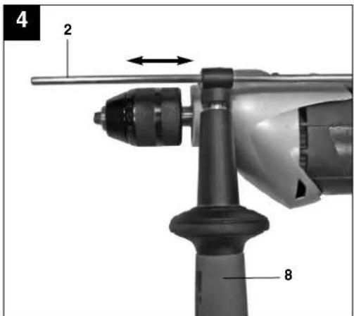



natural_image
Close-up of a drill bit being inserted into a drill bit, showing motion direction (no text or symbols)


"Caution - Read the operating instructions to reduce the risk of injury"

Wear ear-muffs.
The impact of noise can cause damage to hearing.

Wear a breathing mask.
Dust which is injurious to health can be generated when working on wood and other materials.
Never use the device to work on any materials containing asbestos!

Wear safety goggles.
Sparks generated during working or splinters, chips and dust emitted by the device can cause loss of sight.
⚠️ Important!
When using equipment, a few safety precautions must be observed to avoid injuries and damage. Please read the complete operating manual with due care. Keep this manual in a safe place, so that the information is available at all times. If you give the equipment to any other person, give them these operating instructions as well.
We accept no liability for damage or accidents which arise due to non-observance of these instructions and the safety information.
1. Safety regulations
The corresponding safety information can be found in the enclosed booklet.
CAUTION!
Read all safety regulations and instructions.
Any errors made in following the safety regulations and instructions may result in an electric shock, fire and/or serious injury.
Keep all safety regulations and instructions in a safe place for future use.
2. Layout (Fig. 1)
- Drill chuck
- Drill depth stop
- Drill/hammer drill selector switch
- Locking button
- ON/OFF switch
- Speed controller
- Clockwise/Counter-clockwise switch
- Additional handle
- Dust extraction
- Dust extractor adapter
3. Proper use
The drill is designed for drilling holes into wood, iron, non-ferrous metals and rock using the appropriate bits.
The equipment is to be used only for its prescribed purpose. Any other use is deemed to be a case of misuse. The user / operator and not the manufacturer will be liable for any damage or injuries of any kind caused as a result of this.
Please note that our equipment has not been designed for use in commercial, trade or industrial
applications. Our warranty will be voided if the machine is used in commercial, trade or industrial businesses or for equivalent purposes.
4. Technical data
Mains voltage: 230 V \~ 50 Hz
Power input: 750 W
Idling speed: 0-2,700 min
Drilling capacity Concrete 16 mm
Steel 13 mm
Wood 30 mm
Protection class: II / ☐
Weight: 2.45 kg
Sound and vibration
Sound and vibration values were measured in accordance with EN 60745.
L_pA sound pressure level 98 dB(A)
K_pA uncertainty 3
L_WA sound power level 109 dB(A)
K_WA uncertainty 3
Wear ear-muffs.
The impact of noise can cause damage to hearing.
Total vibration values (vector sum of three directions) determined in accordance with EN 60745.
Hammer drilling in concrete (handle)
Vibration emission value a_h = 22.44 m/s^2
K uncertainty = 1.5 m/s²
Hammer drilling in concrete (additional handle)
Vibration emission value a_h = 37.76 m/s^2
K uncertainty = 1.5 m/s ^2
Drilling in metal (handle)
Vibration emission value a_h ≤ 2.5 m/s ^2
K uncertainty = 1.5 m/s²
Drilling in metal (additional handle)
Vibration emission value a_h ≤ 2.5 m/s ^2
K uncertainty = 1.5 m/s²
GB
⚠️ Important!
The vibration value changes according to the area of application of the electric tool and may exceed the specified value in exceptional circumstances.
5. Before starting the equipment
Before you connect the equipment to the mains supply make sure that the data on the rating plate are identical to the mains data.
Always pull the power plug before making adjustments to the equipment.
5.1. Fitting the additional handle (Fig. 2-3/Item 8)
The additional handle (8) enables you to achieve better stability whilst using the hammer drill. Do not use the tool without the additional handle.
The additional handle (8) is secured to the hammer drill by a clamp. During the handle clockwise tightens this clamp. Turning it anti-clockwise will release the clamp.
●The supplied additional handle (8) must first be fitted. To do this, the clamp must be opened by turning the handle until it is wide enough for the additional handle to be slid over the chuck (1) and on to the hammer drill.
●After you have positioned the additional handle (8), turn it to the most comfortable working position for you.
●Now turn the handle in the opposite direction again until the additional handle is secure.
●The additional handle (8) is suitable for both left-handed and right-handed users.
5.2 Fitting and adjusting the depth stop (Fig. 4/Item 2)
The depth stop (2) is held in place by the additional handle (8) by clamping. The clamp can be released and tightened by turning the handle.
●Release the clamp and fit the depth stop (2) in the recess provided for it in the additional handle.
- Set the depth stop (2) to the same level as the drill bit.
●Pull the depth stop back by the required drilling depth.
●Turn the handle on the additional handle (8) until it is secure.
●Now drill the hole until the depth stop (2) touches the workpiece.
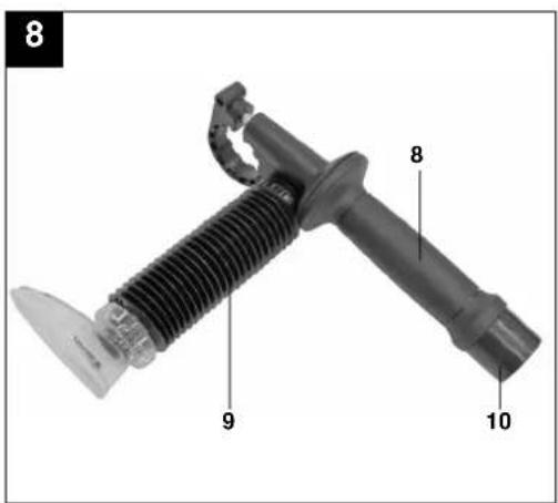
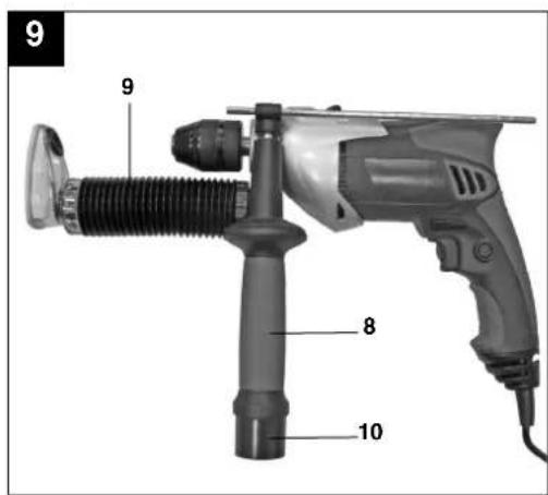
5.3 Fitting the dust extraction system (Fig. 5-9)
The dust extraction system (9) is fitted on the additional handle (8). It can also be used in combination with the depth stop (2). This prevents the work area becoming very dirty.
●Release the cover (A) and the sealing cap (B) by turning the additional handle (8). Several drill bits can be stored in the sealing cap (B) to save space (Fig. 5-6).
●Screw the dust extractor adapter (10) on to the additional handle (8) from underneath.
- Now place the dust extraction system (9) on to the additional handle (8) as shown in Fig. 7 – 8 and secure it by turning it.
Important. There are detents on the cover (A) and the dust extraction system (9) which must be engaged in the corresponding recesses on the additional handle (8) before the cover (A) or dust extraction system (9) can be turned and locked.
- Remove the dust extraction system (9) by following the above in reverse.
●Fit the additional handle (8) on the machine as described in 5.1. Please note that the additional handle (8) must be fitted to the left-hand side of the machine if the dust extraction system (9) is also fitted (Fig. 9).
●The dust extraction system (9) can be fitted to the machine even if the additional handle (8) is fitted.
- If the dust extraction system (9) is not required, the cover (A) and the sealing cap (B) must be fitted to the additional handle (8).
5.4 Fitting the drill bit (Fig. 10)
●Always pull the power plug before making adjustments to the equipment.
●Release the depth stop as described in 5.2 and push it towards the additional handle. In addition the dust extraction system (9) should be removed (see 5.3). This provides free access to the chuck (1).
●This hammer drill is fitted with a keyless chuck (1).
- Open the chuck (1). The drill bit opening must be large enough to fit the drill bit into.
- Select a suitable drill bit. Push the drill bit as far as possible into the chuck opening.
- Close the chuck (1). Check that the drill bit is secure in the chuck (1).
- Check at regular intervals that the drill bit or tool is secure (pull the mains plug).
6. Operation
6.1 ON/OFF switch (Fig. 11/Item 5)
●First fit a suitable drill bit into the tool (see 5.4).
- Connect the mains plug to a suitable socket.
- Position the drill in the position you wish to drill.
To switch on:
Press the ON/OFF switch (5)
Continuous operation:
Secure the ON/OFF switch (5) with the locking button (4).
Important. It may only be locked if the drill is set to rotate clockwise.
To switch off:
Press the ON/OFF switch (5) briefly.
6.2 Adjusting the speed (Fig. 11/Item 5)
●You can infinitely vary the speed whilst using the tool.
- Select the speed by applying a greater or lesser pressure to the ON/OFF switch (5).
- Select the correct speed: The most suitable speed depends on the workpiece, the type of use and the drill bit used.
●Low pressure on the ON/OFF switch (5): Lower speed (suitable for: small screws and soft materials)
●Greater pressure on the ON/OFF switch (5): Higher speed (suitable for large/long screws and hard materials)
Tip: Start drilling holes at low speed. Then increase the speed in stages.
Benefits:
●The drill bit is easier to control when starting the hole and will not slide away.
- You avoid drilling messy holes (for example in tiles).
6.3 Preselecting the speed (Fig. 11/Item 6)
●The speed setting ring (6) enables you to define the maximum speed. The ON/OFF switch (5) can only be pressed to the defined maximum speed setting.
- Set the speed using the setting ring (6) on the ON/OFF switch (5).
- Do not attempt to make this setting whilst the drill is in use.
6.4 Clockwise/Counter-clockwise switch (Fig. 11/Item 7)
●Change switch position only when the drill is at a standstill!
●Switch the direction of the hammer drill using the clockwise/counter-clockwise switch (7):
Direction
Switch
Clockwise (forwards and drill) Pushed in to the right
Counter-clockwise (reverse) Pushed in to the left
6.5 Drill / hammer drill selector switch (Fig. 12/Item 3)
Change switch position only when the drill is at a standstill!
Drill
Drill / hammer drill selector switch (3) in the drill position. (Position A)
Use for: Wood, metal, plastic
Hammer drill
Drill / hammer drill selector switch (3) in the hammer drill position. (Position B)
Use for: Concrete, rock, masonry
6.6 Drilling with the dust extraction system (9)
Use the dust extraction system only for drilling into concrete, bricks and masonry since wood or plastic chips may block the extraction system. Do not drill into metallic materials since hot metal chips can damage the dust extraction system.
●Fit the dust extraction system (9); see point 5.3.
- Connect the dust extractor adapter (10) to the suction hose of a suitable vacuum cleaner. The vacuum cleaner must be suitable for handling the substance that will be extracted. Harmful dust must not be extracted using the dust extraction system (9). Use on materials containing asbestos is prohibited!
●Set the required drilling depth (see point 5.2).
●Mark the drilling position.
●Tip: To prevent the wall being soiled, you can mask the area around the transparent extraction opening with masking tape. Before you use the masking tape, test whether the tape can be removed easily from the wall again in a place that it not easily visible.
●Switch on the vacuum cleaner and place the transparent cover on the front of the dust extraction system (9) over the drilling point so that the drill bit is in front of the mark. Ensure that the transparent cover is in contact with the workpiece or wall.
GB
- Press the drill bit and machine gently against the mark whilst the ON/OFF switch (5) is still set to off.
●Then drill the hole. See the instructions in point 6.7 for more details.
●The dust extraction system (9) must be cleaned after at least every 15 holes. For this purpose remove the dust extraction system (9) and the additional handle (8) as described in points 5.3 and 5.1. Clean the dust extraction system (9) and the interior of the additional handle (8) by carefully tapping them or blowing them through with low pressure compressed air. - If the extraction performance is poor, check the dust extraction system (9) for possible blockages or dirt.
●The transparent cover is enclosed in a protective ring to prevent it from suffering damage. This protective ring should be replaced as soon as it is damaged or worn.
6.7 Tips for working with your hammer drill
6.7.1 Drilling concrete and masonry
●Switch the Drill/Hammer drill selector switch (3) to position B (Hammer drill).
●Always use carbide drill bits and a high speed setting for drilling into masonry and concrete.
6.7.2 Drilling steel
●Switch the drill / hammer drill selector switch (3) to position A (drill).
●Always use HSS drill bits (HSS = high speed steel) and a low speed setting for drilling steel.
- We recommend that you lubricate the hole with a suitable cutting fluid to prevent unnecessary drill bit wear.
6.7.3 Inserting/Removing screws
●Switch the Drill/Hammer drill selector switch (3) to position A (drill).
●Use a low speed setting
6.7.4 Starting holes
If you wish to drill a deep hole in a hard material (such as steel), we recommend that you start the hole with a smaller drill bit.
6.7.5 Drilling tiles
●To start the hole, switch the drill / hammer drill selector switch (3) to position A (drill).
- Switch the drill / hammer drill selector switch (3) to position B (hammer drill) as soon as the drill bit has passed through the tiles.
7. Replacing the power cable
If the power cable for this equipment is damaged, it must be replaced by the manufacturer or its after-sales service or similarly trained personnel to avoid danger.
8. Cleaning, maintenance and ordering of spare parts
Always pull out the mains power plug before starting any cleaning work.
8.1 Cleaning
- Keep all safety devices, air vents and the motor housing free of dirt and dust as far as possible. Wipe the equipment with a clean cloth or blow it with compressed air at low pressure.
●We recommend that you clean the device immediately each time you have finished using it.
●Clean the equipment regularly with a moist cloth and some soft soap. Do not use cleaning agents or solvents; these could attack the plastic parts of the equipment. Ensure that no water can seep into the device.
8.2 Carbon brushes
In case of excessive sparking, have the carbon brushes checked only by a qualified electrician. Important! The carbon brushes should not be replaced by anyone but a qualified electrician.
8.3 Maintenance
There are no parts inside the equipment which require additional maintenance.
8.4 Ordering replacement parts:
Please quote the following data when ordering replacement parts:
●Type of machine
●Article number of the machine
●Identification number of the machine
●Replacement part number of the part required For our latest prices and information please go to www.einhell.com.au
9. Disposal and recycling
The unit is supplied in packaging to prevent its being damaged in transit. This packaging is raw material and can therefore be reused or can be returned to the raw material system.
The unit and its accessories are made of various types of material, such as metal and plastic.
Defective components must be disposed of as special waste. Ask your dealer or your local council.
The guarantee provided in this Guarantee Certificate is given by Einhell Australia Pty Limited ACN 134 632 858 of 6/166 Wellington Street, Collingwood, Victoria (Telephone number 1300 922 271) (Einhell Express Guarantee).
GB GUARANTEE CERTIFICATE
Dear Customer,
All of our products undergo strict quality checks. In the unlikely event that your device develops a fault, please contact our service department at the address shown on this guarantee certificate. Of course, if you would prefer to call us then we are also happy to offer our assistance under the service number printed below. Please note the following terms under which claims under the Einhell Express Guarantee can be made:
- The benefits conferred by the Einhell Express Guarantee are in addition to all rights and remedies which you may be entitled to under the Australian Consumer Law, and any other statutory rights you may have under other applicable laws. This Einhell Express Guarantee does not exclude, restrict or modify any such rights or remedies.
We do not charge you for the Einhell Express Guarantee. - Our goods come with guarantees that cannot be excluded under the Australian Consumer Law. You are entitled to a replacement or refund for a major failure and for compensation for any other reasonably foreseeable loss or damage. You are also entitled to have the goods repaired or replaced if the goods fail to be of acceptable quality and the failure does not amount to a major failure.
- The Einhell Express Guarantee only covers problems caused by material or manufacturing defects, and our liability under the Einhell Express Guarantee is limited, at our discretion, to the rectification of these defects or replacement of the product. Please note that the product has not been designed for use in commercial, trade or industrial applications. Consequently, the Einhell Express Guarantee will not apply if the product is used in commercial, trade or industrial applications or for other equivalent activities.
- The following are also excluded from the Einhell Express Guarantee: compensation for transport damage, damage caused by failure to comply with the installation/assembly instructions or damage caused by unprofessional installation, failure to comply with the operating instructions (e.g. connection to the wrong mains voltage or current type), misuse or inappropriate use (such as overloading of the product or use of non-approved tools or accessories), failure to comply with the maintenance and safety regulations, ingress of foreign bodies into the product (e.g. sand, stones or dust), effects of force or external influences (e.g. damage caused by the product being dropped) and normal wear resulting from proper operation of the product. The Einhell Express Guarantee will also not apply if any attempt is made to tamper with the product.
- The Einhell Express Guarantee is valid for a period of 2 years starting from the purchase date of the product. Claims made under the Einhell Express Guarantee should be submitted before the end of this guarantee period and within two weeks of the defect being noticed. No claims under the Einhell Express Guarantee will be accepted if submitted after the end of this guarantee period. The original guarantee period remains applicable to the device even if repairs are carried out or parts are replaced. In such cases, the work performed or parts fitted will not result in an extension of the guarantee period for the Einhell Express Guarantee, and the Einhell Express Guarantee will not apply for the work performed or parts fitted. This also applies when an on-site service is used.
- To make a claim under the Einhell Express Guarantee, please send the relevant product postage-free to the address shown below and enclose either the original or a copy of your sales receipt or another dated proof of purchase. It would help us if you could describe the nature of the problem in as much detail as possible. If the defect is covered by the Einhell Express Guarantee, your product will be repaired immediately and returned to you, or we will send you a new device (at our election).
Any costs incurred by you in making a claim under this Einhell Express Guarantee, unless specified otherwise in this guarantee certificate, must be borne by you.
Of course, we are also happy to offer a chargeable repair service for any defects which are not covered by the scope of the Einhell Express Guarantee or for products which are no longer covered by the Einhell Express Guarantee. To take advantage of this service, please send the product to our service address.
EINHELL AUSTRALIA PTY LTD
6/166 Wellington Street
Collingwood VIC 3066
Australia
Phone: 1300 922 271
- ⚠️ Important!
- Safety regulations
- CAUTION!
- Layout (Fig. 1)
- Proper use
- Technical data
- Sound and vibration
- Wear ear-muffs.
- Hammer drilling in concrete (handle)
- Hammer drilling in concrete (additional handle)
- Drilling in metal (handle)
- Drilling in metal (additional handle)
- GB
- Before starting the equipment
- Fitting the additional handle (Fig. 2-3/Item 8)
- Fitting and adjusting the depth stop (Fig. 4/Item 2)
- Fitting the dust extraction system (Fig. 5-9)
- Fitting the drill bit (Fig. 10)
- Operation
- ON/OFF switch (Fig. 11/Item 5)
- To switch on:
- Continuous operation:
- To switch off:
- Adjusting the speed (Fig. 11/Item 5)
- Benefits:
- Preselecting the speed (Fig. 11/Item 6)
- Clockwise/Counter-clockwise switch (Fig. 11/Item 7)
- Direction
- Switch
- Drill / hammer drill selector switch (Fig. 12/Item 3)
- Drill
- Hammer drill
- Drilling with the dust extraction system (9)
- Tips for working with your hammer drill
- Drilling concrete and masonry
- Drilling steel
- Inserting/Removing screws
- Starting holes
- Drilling tiles
- Replacing the power cable
- Cleaning, maintenance and ordering of spare parts
- Cleaning
- Carbon brushes
- Maintenance
- Ordering replacement parts:
- Disposal and recycling
- GB GUARANTEE CERTIFICATE
Brand : EINHELL
Model : RT-ID 75
Category : Drill