
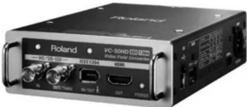
VC-50HD - Video Converter ROLAND - Free user manual and instructions
Find the device manual for free VC-50HD ROLAND in PDF.


| Product Type | Video Converter |
| Brand | Roland |
| Model | VC-50HD |
| Input Interfaces | HDMI, SDI, CVBS (Composite) |
| Output Interfaces | HDMI, SDI |
| Max Resolution | 1920 x 1080 (1080p) |
| Video Standards | NTSC, PAL |
| Audio Support | Embedded audio via HDMI/SDI |
| Dimensions (W x H x D) | 200 x 150 x 40 mm |
| Weight | 0.5 kg |
| Power Supply | DC 12V, 1A via external adapter |
| Operating Temperature | 0°C to 40°C |
| Storage Temperature | -20°C to 60°C |
| Main Functions | Signal conversion, scaling, format conversion between HDMI, SDI, and CVBS |
| Maintenance | Clean with a soft dry cloth; do not use liquids |
| Safety | Use only supplied power adapter; avoid exposure to moisture |
| Spare Parts | Power adapter available; no user-serviceable parts inside |
| General Information | Professional-grade video converter suitable for broadcast and production |
Frequently Asked Questions - VC-50HD ROLAND
User questions about VC-50HD ROLAND
0 question about this device. Answer the ones you know or ask your own.
Ask a new question about this device
Download the instructions for your Video Converter in PDF format for free! Find your manual VC-50HD - ROLAND and take your electronic device back in hand. On this page are published all the documents necessary for the use of your device. VC-50HD by ROLAND.
USER MANUAL VC-50HD ROLAND
Before using this unit, carefully read the sections entitled: "USING THE UNIT SAFELY" and "IMPORTANT NOTES" (p. 3-5; p. 6-7).
These sections provide important information concerning the proper operation of the unit. Additionally, in order to feel assured that you have gained a good grasp of every feature provided by your new unit, Owner's Manual should be read in its entirety. The manual should be saved and kept on hand as a convenient reference.
For the U.K.
IMPORTANT: THE WIRES IN THIS MAINS LEAD ARE COLOURED IN ACCORDANCE WITH THE FOLLOWING CODE.
BLUE: NEUTRAL
BROWN: LIVE
As the colours of the wires in the mains lead of this apparatus may not correspond with the coloured markings identifying the terminals in your plug, proceed as follows:
The wire which is coloured BLUE must be connected to the terminal which is marked with the letter N or coloured BLACK.
The wire which is coloured BROWN must be connected to the terminal which is marked with the letter L or coloured RED.
Under no circumstances must either of the above wires be connected to the earth terminal of a three pin plug.
INSTRUCTIONS FOR THE PREVENTION OF FIRE, ELECTRIC SHOCK, OR INJURY TO PERSONS
About ⚠ WARNING and ⚠ CAUTION Notices
| WARNING | Used for instructions intended to alert the user to the risk of death or severe injury should the unit be used improperly. |
| CAUTION | Used for instructions intended to alert the user to the risk of injury or material damage should the unit be used improperly.* Material damage refers to damage or other adverse effects caused with respect to the home and all its furnishings, as well to domestic animals or pets. |
About the Symbols
| The △ symbol alerts the user to important instructions or warnings. The specific meaning of the symbol is determined by the design contained within the triangle. In the case of the symbol at left, it is used for | |
| The Ⓧ symbol alerts the user to items that must never be carried out (are forbidden). The specific thing that must not be done is indicated by the design contained within the circle. In the case of the symbol at left, it means that the unit must never be disassembled. | |
| The ● symbol alerts the user to things that must be carried out. The specific thing that must be done is indicated by the design contained within the circle. In the case of the symbol at left, it means that the power-cord plug must be unplugged from the outlet. |
ALWAYS OBSERVE THE FOLLOWING
! WARNING
- Do not open (or modify in any way) the unit or its AC adaptor.

- Do not attempt to repair the unit, or replace parts within it (except when this manual provides specific instructions directing you to do so). Refer all servicing to your retailer, the nearest Roland Service Center, or an authorized Roland distributor, as listed on the "Information" page.

! WARNING
- Never install the unit in any of the following locations.

- Subject to temperature extremes (e.g., direct sunlight in an enclosed vehicle, near a heating duct, on top of heat-generating equipment); or are

- Damp (e.g., baths, washrooms, on wet floors); or are
- Exposed to steam or smoke; or are
- Subject to salt exposure; or are
- Humid; or are
- Exposed to rain; or are
• Dusty or sandy; or are - Subject to high levels of vibration and shakiness.
- Make sure you always have the unit placed so it is level and sure to remain stable. Never place it on stands that could wobble, or on inclined surfaces.

- Be sure to use only the AC adaptor supplied with the unit. Also, make sure the line voltage at the installation matches the input voltage specified on the AC adaptor's body. Other AC adaptors may use a different polarity, or be designed for a different voltage, so their use could result in damage, malfunction, or electric shock.

- Use only the attached power-supply cord. Also, the supplied power cord must not be used with any other device.


WARNING
- Do not excessively twist or bend the power cord, nor place heavy objects on it. Doing so can damage the cord, producing severed elements and short circuits. Damaged cords are fire and shock hazards!

- This unit, either alone or in combination with an amplifier and headphones or speakers, may be capable of producing sound levels that could cause permanent hearing loss. Do not operate for a long period of time at a high volume level, or at a level that is uncomfortable. If you experience any hearing loss or ringing in the ears, you should immediately stop using the unit, and consult an audiologist.

- Do not allow any objects (e.g., flammable material, coins, pins); or liquids of any kind (water, soft drinks, etc.) to penetrate the unit.

- Immediately turn the power off, remove the AC adaptor from the outlet, and request servicing by your retailer, the nearest Roland Service Center, or an authorized Roland distributor, as listed on the "Information" page when:

- The AC adaptor, the power-supply cord, or the plug has been damaged; or
- If smoke or unusual odor occurs
- Objects have fallen into, or liquid has been spilled onto the unit; or
- The unit has been exposed to rain (or otherwise has become wet); or
- The unit does not appear to operate normally or exhibits a marked change in performance.


WARNING
- In households with small children, an adult should provide supervision until the child is capable of following all the rules essential for the safe operation of the unit.

- Protect the unit from strong impact. (Do not drop it!)

- Do not force the unit's power-supply cord to share an outlet with an unreasonable number of other devices. Be especially careful when using extension cords—the total power used by all devices you have connected to the extension cord's outlet must never exceed the power rating (watts/amperes) for the extension cord. Excessive loads can cause the insulation on the cord to heat up and eventually melt through.

- Before using the unit in a foreign country, consult with your retailer, the nearest Roland Service Center, or an authorized Roland distributor, as listed on the "Information" page.

- Batteries must never be recharged, heated, taken apart, or thrown into fire or water.

- Never expose Battery or Battery to excessive heat such as sunshine, fire or the like.


CAUTION
- The unit and the AC adaptor should be located so their location or position does not interfere with their proper ventilation.

• Always grasp only the plug on the AC adaptor cord when plugging into, or unplugging from, an outlet or this unit.

- At regular intervals, you should unplug the AC adaptor and clean it by using a dry cloth to wipe all dust and other accumulations away from its prongs. Also, disconnect the power plug from the power outlet whenever the unit is to remain unused for an extended period of time. Any accumulation of dust between the power plug and the power outlet can result in poor insulation and lead to fire.

- Try to prevent cords and cables from becoming entangled. Also, all cords and cables should be placed so they are out of the reach of children.

- Never climb on top of, nor place heavy objects on the unit.

- Never handle the AC adaptor or its plugs with wet hands when plugging into, or unplugging from, an outlet or this unit.

- Before moving the unit, disconnect the AC adaptor and all cords coming from external devices.

- Before cleaning the unit, turn off the power and unplug the AC adaptor from the outlet (p. 21).

- Whenever you suspect the possibility of lightning in your area, disconnect the AC adaptor from the outlet.


CAUTION
- If used improperly, batteries may explode or leak and cause damage or injury. In the interest of safety, please read and observe the following precautions (p.16).

- Carefully follow the installation instructions for batteries, and make sure you observe the correct polarity.

- Avoid using new batteries together with used ones. In addition, avoid mixing different types of batteries.

- Remove the batteries whenever the unit is to remain unused for an extended period of time.
- If a battery has leaked, use a soft piece of cloth or paper towel to wipe all remnants of the discharge from the battery compartment. Then install new batteries. To avoid inflammation of the skin, make sure that none of the battery discharge gets onto your hands or skin. Exercise the utmost caution so that none of the discharge gets near your eyes. Immediately rinse the affected area with running water if any of the discharge has entered the eyes.
- Never keep batteries together with metallic objects such as ballpoint pens, necklaces, hairpins, etc.
• Used batteries must be disposed of in compliance with whatever regulations for their safe disposal that may be observed in the region in which you live.

- Should you remove ferrite cores, screws to fasten battery plate holder or screws removed from VC-50HD's top panel, keep them in a safe place out of children's reach, so there is no chance of them being swallowed accidentally. If the insulating tube happens to comes loose, then to prevent it from being accidentally swalled, store it out of the reach of small children.

Power Supply: Use of Batteries
- Do not connect this unit to same electrical outlet that is being used by an electrical appliance that is controlled by an inverter (such as a refrigerator, washing machine, microwave oven, or air conditioner), or that contains a motor. Depending on the way in which the electrical appliance is used, power supply noise may cause this unit to malfunction or may produce audible noise. If it is not practical to use a separate electrical outlet, connect a power supply noise filter between this unit and the electrical outlet.
- The AC adaptor will begin to generate heat after long hours of consecutive use. This is normal, and is not a cause for concern.
- The use of an AC adaptor is recommended as the unit's power consumption is relatively high. Should you prefer to use batteries, please use the alkaline type.
- When installing or replacing batteries, always turn off the power on this unit and disconnect any other devices you may have connected. This way, you can prevent malfunction and/or damage to speakers or other devices.
- Before connecting this unit to other devices, turn off the power to all units. This will help prevent malfunctions and/or damage to speakers or other devices.
Placement
- Using the unit near power amplifiers (or other equipment containing large power transformers) may induce hum. To alleviate the problem, change the orientation of this unit; or move it farther away from the source of interference.
- This device may interfere with radio and television reception. Do not use this device in the vicinity of such receivers.
- Noise may be produced if wireless communications devices, such as cell phones, are operated in the vicinity of this unit. Such noise could occur when receiving or initiating a call, or while conversing. Should you experience such problems, you should relocate such wireless devices so they are at a greater distance from this unit, or switch them off.
- Do not expose the unit to direct sunlight, place it near devices that radiate heat, leave it inside an enclosed vehicle, or otherwise subject it to temperature extremes. Excessive heat can deform or discolor the unit.
- When moved from one location to another where the temperature and/or humidity is very different, water droplets (condensation) may form inside the unit. Damage or malfunction may result if you attempt to use the unit in this condition. Therefore, before using the unit, you must allow it to stand for several hours, until the condensation has completely evaporated.
- Depending on the material and temperature of the surface on which you place the unit, its rubber feet may discolor or mar the surface. You can place a piece of felt or cloth under the rubber feet to prevent this from happening. If you do so, please make sure that the unit will not slip or move accidentally.
Maintenance
- For everyday cleaning wipe the unit with a soft, dry cloth or one that has been slightly dampened with water. To remove stubborn dirt, use a cloth impregnated with a mild, non-abrasive detergent. Afterwards, be sure to wipe the unit thoroughly with a soft, dry cloth.
- Never use benzine, thinners, alcohol or solvents of any kind, to avoid the possibility of discoloration and/or deformation.
Repairs and Data
- Please be aware that all data contained in the unit's memory may be lost when the unit is sent for repairs. Important data should always be written down on paper (when possible). During repairs, due care is taken to avoid the loss of data. However, in certain cases (such as when circuitry related to memory itself is out of order), we regret that it may not be possible to restore the data, and Roland assumes no liability concerning such loss of data.
Additional Precautions
- Please be aware that the contents of memory can be irretrievably lost as a result of a malfunction, or the improper operation of the unit. To protect yourself against the risk of loosing important data, we recommend that you periodically write down on paper.
- Unfortunately, it may be impossible to restore the contents of data that was stored on internal memory once it has been lost. Roland Corporation assumes no liability concerning such loss of data.
- Use a reasonable amount of care when using the unit's buttons, sliders, or other controls; and when using its jacks and connectors. Rough handling can lead to malfunctions.
- When connecting / disconnecting all cables, grasp the connector itself—never pull on the cable. This way you will avoid causing shorts, or damage to the cable's internal elements.
- To avoid disturbing your neighbors, try to keep the unit's volume at reasonable levels (especially when it is late at night).
- When you need to transport the unit, package it in the box (including padding) that it came in, if possible. Otherwise, you will need to use equivalent packaging materials.
Copyright
- This product can be used to record or duplicate audio or visual material without being limited by certain technological copy-protection measures. This is due to the fact that this product is intended to be used for the purpose of producing original music or video material, and is therefore designed so that material that does not infringe copyrights belonging to others (for example, your own original works) can be recorded or duplicated freely.
- Do not use this unit for purposes that could infringe on a copyright held by a third party. We assume no responsibility whatsoever with regard to any infringements of third-party copyrights arising through your use of this unit.
USING THE UNIT SAFELY 3
IMPORTANT NOTES......6
Contents 8
Check the included items 9
Main features .... 10
The VC-50HD's conversion capabilities 11
Names of things and what they do 12
Front panel....12
Side panel.... 13
Placement and connections 14
Power supply 15
Connecting the AC adaptor 15
Installing AA batteries 16
Attaching an external battery.... 18
Turning the power on/off 20
Turning the power on 20
Turning the power off....21
Connections with video devices 22
Converting SDI to IEEE 1394 22
Mode settings to output HDV 23
Mode settings to output DV 23
Mode settings to output MPEG-2 TS 23
Converting IEEE 1394 to SDI 24
Mode settings for converting IEEE 1394 to SDI 24
Using the VC-50HD with the F-1 25
Connecting Monitors/Mixers 26
Connecting monitor equipment 26
Using the SDI thru-out....26
Other mode settings.... 27
Specifying the audio input/output channels 27
Accepting remote control 28
Appendices 29
Troubleshooting....29
Main Specifications.... 30
Dimensions 31
Block Diagram....31
Timecode 32
Memo 33
Check the included items
The following items are included. Please make sure that all items are present. If anything is missing, please contact your dealer.
The VC-50HD itself
Battery case

natural_image
Black rectangular electronic component with three leads (no visible text or symbols)AC adaptor and power cable

natural_image
Coiled black cables and a rectangular device with connectors (no visible text or symbols)* A ferrite core is attached when the cable is shipped from the factory. Do not remove this ferrite core.
Adaptor cable (AC adaptor to XLR 4-pin connector)

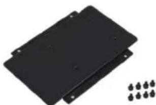
Battery plate holder and fastening screws (8 pcs.)
natural_image
Two black plastic panels with mounting holes and a row of small metallic pins (no text or symbols visible)* Compatible with the P-V2 (V-Plate) made by the IDX Corporation and with the QRC-GOLD made by Anton/Bauer, Inc.
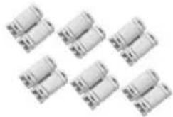
Ferrite cores (6 pcs.)
natural_image
Six identical cylindrical electronic components arranged in a 2x2 grid (no visible text or symbols)Owner's manual (this document)
Conversion between HD/SD-SDI and HDV/DV
The VC-50HD provides a compact solution for converting between high-quality uncompressed HD/SD-SDI video and the HDV/DV video widely used by video devices. It allows a camera or deck with SDI input and output connectors to be connected to an HDV/DV device with IEEE 1394 (i.LINK) connectors, enabling high-quality image conversion regardless of which device is the source.
High-quality conversion of MPEG-2 TS (35 Mbps/50 Mbps)
When receiving an HD/SD-SDI input and sending it from IEEE 1394, the signal can be converted not only to HDV/DV but also to MPEG-2 TS 35 Mbps or 50 Mbps. This capability allows recording with even better quality than 25 Mbps HDV/DV. You can take your laptop computer or an F-1 (version 2 or later) to the shooting location, and capture high-quality video for online use at the same time that you're shooting. Of course, conversion from MPEG-2 TS to SDI is also supported.
Three-way power supply support
In addition to the AC adaptor, the VC-50HD can be powered from an external battery or from AA batteries, allowing use in a variety of situations. AA batteries installed in the internal battery case will operate as a backup power supply. This allows the unit to continue operating seamlessly even if the AC adaptor should become unplugged or if the external battery is replaced.
Compact and tough body
Like the F-1, the VC-50HD is designed for use in the field (Field Oriented Design). Its compact and tough design ensures that it can be used reliably in rugged conditions.
Provides a low-cost monitoring environment
An HDMI output connector is provided on the VC-50HD's front panel. This can be connected to a computer display or TV monitor, providing a low-cost monitoring environment.
* MMP (Moore Microprocessor Portfolio) refers to a patent portfolio concerned with microprocessor architecture, which was developed by Technology Properties Limited (TPL). Roland has licensed this technology from the TPL Group.
* IDX and ENDURA are registered trademarks of IDX Company, Ltd.
* Anton Bauer is registered trademark of Anton/Bauser, Inc.
The VC-50HD's conversion capabilities
The format of the input to the VC-50HD is detected automatically. The VC-50HD is capable of performing conversions in either direction (SDI to IEEE 1394 and IEEE 1394 to SDI). The formats that can be converted and output are shown below.
| SDI IEEE 1994 | ||
| HD-SDI | 1080/59.94i1080/50i720/59.94p720/50p | HDV |
| 35Mbps MPEG-2 TS | ||
| 50Mbps MPEG-2 TS | ||
| SD-SDI 480/59.94i(NTSC)576/50i(PAL) | DV | |
| 9Mbps MPEG-2 TS | ||
| 12Mbps MPEG-2 TS | ||
* The VC-50HD does not support up/down-conversion, I/P conversion, or frame rate conversion.
* If you select MPEG-2 TS as the IEEE 1394 output, and input SD-SDI, the bit rate will be approximately one quarter of what it is when HD-SDI is input.
Names of things and what they do
Front panel
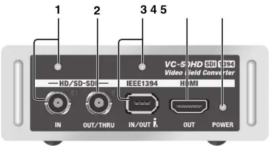
1. HD/SD-SDI input connector and indicator
This connector allows SDI signals to be input. Connect it to the SDI output connector of your camera or deck. If an input signal is present, the indicator will light in one of the following colors. If there is no input, the indicator will blink.
• HD-SDI (1080i) : green
•HD-SDI (720p): orange
- SD-SDI: red
2. HD/SD-SDI output/thru out connector
This connector outputs an SDI signal. Connect this to the SDI input connector of your deck or other video recording device. You can also use this as a thru-out for the SDI signal that is being input to the VC-50HD, in order to send ("thru-out") this signal to a video mixer or similar device.
3. IEEE 1394 connector and indicator
This connector inputs and outputs an HDV/DV or other signal via IEEE 1394. Connect it to the IEEE 1394 (i.LINK) connector of your camera, deck, or computer. If input is present, the indicator will light in one of the following colors. If there is no input, the indicator will blink.
•HDV/MPEG-2 TS: green
•DV : red

If the F-1 (version 2 or later) is connected as the output destination device, you'll be able to edit the VC-50HD's settings via remote control from the F-1.

Carefully check the shape of the IEEE 1394 connector before connecting it. Connecting it in the reversed orientation may damage components inside the VC-50HD, causing malfunctions.
4. HDMI output connector
Connect this to a monitor device that has an HDMI input, such as a television or computer display.
5. POWER indicator
This indicator will light when the VC-50HD is powered up.
* This indicator will blink if the AA batteries run low. If this begins blinking, replace the batteries as soon as possible.
Side panel

1. USB connector
This can be connected to your computer, allowing the VC-50HD's settings to be switched via remote control. For the remote control software, please refer to the following Roland website.
http://www.rolandsystemsgroup.net/
2. Mode select switches
These switches allow you to switch the VC-50HD's input/output mode and control mode. Use a fine-pointed pen or similar object to change the setting of a switch. Switches 1-6 make the following settings.
•1: Conversion direction (from SDI to IEEE 1394, or from IEEE 1394 to SDI)
•2: In conjunction with switch 3, specifies the SDI audio input/output channels
•3: In conjunction with switch 2, specifies the SDI audio / output channels
•4: Codec for IEEE 1394 input/output (HDV/DV or MPEG-2 TS)
- 5: In conjunction with switch 4, this specifies the HDV/DV or MPEG-2 TS (35Mbps/50Mbps) setting.
* If MPEG-2 TS is selected, the setting will be 9 Mbps/12 Mbps if the input signal is SD.
- 6: Control mode (local or remote control of the VC-50HD)
* If switch 6 is ON, switches 1 thru 5 will be disabled and remote control will be accepted.
* When shipped from the factory, these switches are set as follows.

If all switches are OFF, the following settings will be in effect.
- HD/SD-SDI input is converted to HDV/DV and output.
- Channels 1/2 of SDI embedded audio are output without change as channels 1/2 of HDV/DV.
- Remote control is not accepted.
3. POWER switch
This turns the VC-50HD's power on/off. If mode select switch 6 is on, the POWER switch will not operate.

Mode select switch 6 specifies the remote control setting. For details on remote control, refer to "Accepting remote control" (p. 28).
4. DC IN connector
Connect the AC adaptor or an external video camera battery here.

For details on attaching an external battery to the VC-50HD, refer to "Attaching an external battery" (p. 18).
Placement and connections
Cooling vents
Do not block the cooling vents located on the sides of the VC-50HD. When placing the VC-50HD, make sure to leave at least 2 ~cm of space in front of the cooling vents. If the air intake or exhaust are blocked, the interior temperature will rise, possibly causing heat-related malfunctions.

Theft prevention lock
A commercially available security cable can be attached to the VC-50HD to prevent theft. For details, refer to the following URL. http://www.kensington.com/

Connection cables
Ferrite cores
Six ferrite cores are included with the VC-50HD. Attach these ferrite cores to the IEEE 1394 cables, HDMI cables, and USB cables that are connected to the VC-50HD. Place the ferrite core around the cable and press it closed until it clicks shut.
* A ferrite core is attached to the included AC adaptor when it is shipped from the factory. Do not remove this ferrite core. Attach the ferrite cores to the input/output cables.
* Be careful not to pinch your hand when attaching the ferrite core.

Cable quality
Use high-quality cables to make connections. Poor-quality cables may not convey the signal correctly.
Power supply
In addition to being powered by the AC adaptor, the VC-50HD can also be powered by AA batteries in the internal battery case, or by an external battery.
The AA batteries will operate as a backup power supply. This allows the VC-50HD to continue operating even while you exchange the external battery.
* Even if AA batteries are installed, the power supplied from the DC IN connector will take priority.
Connecting the AC adaptor
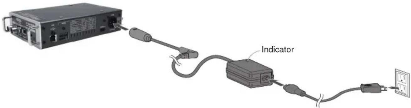
1. Connect the adaptor cable to the AC adaptor
Before you connect the AC adaptor to the VC-50HD, connect the adaptor cable as shown in the illustration below.
* Never detach the insulating tube attached to the AC adapter to XLR 4-pin connector adapter cable.

natural_image
Pure electrical circuit lines without any symbols2. Connect the AC adaptor to the VC-50HD
Place the AC adaptor so the side with the indicator (see illustration) faces upwards and the side with textual information faces downwards. The indicator will light when you plug the AC adaptor into an AC outlet.
Installing AA batteries
Install commercially available AA batteries into the VC-50HD, following the procedure described below.
* Zinc-carbon batteries cannot be used. You may use nickel-metal hydride batteries or alkaline batteries.
* Even if you're using the AC adaptor, leaving AA batteries installed will provide a backup power supply in the event that the AC adaptor cable is inadvertently disconnected.
* Even if AA batteries are installed, the power supply from the DC IN connector will take priority.
* It is dangerous to insert your hand or fingers into the opening of the VC-50HD when inserting or removing the battery case. Do not insert your hand or fingers into the opening.
* When using the AA batteries in the battery case, do not subject the VC-50HD to vibration or physical shock. The power may turn off if this occurs.
* The VC-50HD cannot recharge nickel-metal hydride batteries. You will need to acquire a commercially available charger.
* Carefully read and observe all precautions and handling instructions that accompany the AA batteries.
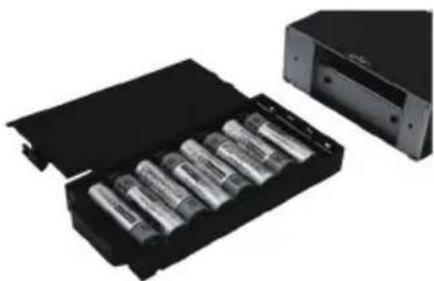
1. Install eight AA batteries in the battery case
Taking care to observe the correct polarity (orientation), insert the batteries in accordance with the symbols imprinted inside the battery case.
natural_image
Black-and-white photo of a battery pack with multiple cylindrical batteries, next to an open black case (no visible text or symbols)2. Remove the rear cover
Loosen the two screws that fasten the VC-50HD's rear cover, and remove the rear cover.
* The screws cannot be removed from the rear cover.

natural_image
Hand holding a rectangular electronic device with directional arrows indicating motion or force (no text or symbols visible)3. Insert the battery case into the VC-50HD
Insert the battery case into the VC-50HD as it was originally. When doing so, take care that no metallic foreign object touches the terminals of the battery case. This could short-circuit the battery, possibly causing it to overheat or ignite.

natural_image
Close-up of hands holding a black electronic device with an arrow indicating motion (no text or symbols visible)4. Close the rear cover
Close the rear cover as it was originally, and use the two screws to fasten it.
Caution regarding batteries
* When inserting batteries, take care to observe to observe the correct polarity (orientation) in accordance with the symbols imprinted inside the battery case.
* Remove the batteries if you won't be using the VC-50HD for an extended period of time (several months or longer).
* Do not mix fresh batteries with used batteries, and do not mix batteries of differing types.
* If a battery should leak, use a soft cloth to carefully wipe off any leaked electrolyte from the battery case, and then install new batteries. Battery electrolyte that contacts your skin may cause a rash. Battery electrolyte is harmful to the eyes; if any gets into your eyes, thoroughly rinse your eyes with water.
* Do not carry or store batteries together with metallic objects such as pens, necklaces, or hairpins.
* Carefully read and observe any precautions and handling instructions that accompany the batteries.
Continuous use of AA batteries
When using nickel-metal hydride batteries or alkaline batteries, the battery life for continuous operation is as follows.
| Battery Type | Operation Time |
| Nickel Hydride | Approx 2 hours |
| Alkaline | Approx 30 minutes (backup) |
* The above times are approximate. They will change depending on conditions of use, such as the temperature.
Attaching an external battery
If you want to supply power from an external battery, you must first attach the holder included with the VC-50HD to the battery plate. The included holder is compatible with the P-V2 (V-Plate) made by the IDX Company, Ltd. and with the QRC-GOLD made by Anton/Bauer, Inc.

The battery, battery plate, and power supply cable are not included. You'll need to purchase these separately from the battery manufacturer.

natural_image
Stacked electronic devices with ports and connectors, no visible text or symbols1. Attach the battery plate (sold separately) to the included holder
Use the four included screws to attach the battery plate (sold separately) to the included holder. Refer to the photograph below.

natural_image
Two-panel image showing a disassembled electronic device with screwdriver and accessories, and a hand holding a black electronic device with a switch (no visible text or symbols)2. Remove the screws from the top surface of the VC-50HD.
Remove four screws from the top surface of the VC-50HD. To do so, you'll need to use a screwdriver (no. 1 screwdriver) that is finer-tipped than the screwdriver you used in step 1. Keep the removed screws in a safe place.

natural_image
Close-up of a hand holding a device with a screwdriver inserted, no visible text or symbols3.Fasten the battery plate and holder to the top of the VC-50HD
Using the four included screws, fasten the battery plate and holder that you assembled in step 1 to the top surface of the VC-50HD.
* Use caution, since excessive tightening may damage the VC-50HD.

natural_image
Close-up of hands using a screwdriver to adjust or install electronic components on a device (no visible text or symbols)4. Attach the external battery
Attach the external battery, and connect its power cable to the VC-50HD's DC IN connector.

natural_image
Close-up of hands installing a black electronic device on a rack, no visible text or symbolsNOTE
The eight screws included with the VC-50HD are only for attaching the battery plate holder. The four screws removed from the top surface of the VC-50HD cannot be used for this purpose. When attaching an external battery, be aware of the different types of screws.
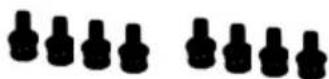
Screws for fastening

Removed screws
Regarding the external battery
The VC-50HD is compatible with external batteries that produce an output voltage in the range of 9 volts to 20 volts. Please use a product that falls within this range.
A fully charged ENDURA-10 (E-10) made by the IDX Company, Ltd. will provide approximately ten hours of continuous operation.
* The continuous operating time will depend on the temperature and other conditions of use.
Turning the power on
After you have made connections correctly, you must turn on the power as described below. Incorrect operation may cause malfunctions or may damage the speakers of your monitoring system.
* Due to a circuitry-protection feature, the VC-50HD requires a few moments after it has been powered up before it is ready for normal operation.
* If you are operating the unit only on AA batteries, the POWER indicator will blink when the batteries run low. Replace the batteries as soon as possible.
On the side of the VC-50HD, slide the POWER switch in the direction of the arrow and hold it for two or three seconds until the POWER indicator lights.
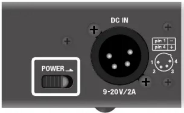

If mode select switch 6 is on, so that remote control is activated, the VC-50HD's power will automatically be turned on when power is supplied at DC IN. In this case, the POWER switch is disabled. However, the power will not turn on automatically if you're using only the internal AA batteries as the power supply, with nothing connected to the DC IN connector. Use the POWER switch to turn the power on/off.

Mode select switch 6 is the remote control setting. For details on remote control, refer to “Accepting remote control” (p. 28).
Turning the power off
Slide the POWER switch in the direction of the arrow and hold it for two or three seconds until the POWER indicator goes out.

If mode select switch 6 is on, so that remote control is activated, operating the POWER switch will not turn off the power. To turn off the power, disconnect the power cable.

Mode select switch 6 is the remote control setting. For details on remote control, refer to “Accepting remote control” (p. 28).
Caution regarding the power supply
* If you're using an external battery without installing AA batteries internally, the VC-50HD's power will be turned off if you disconnect the power cable from the DC IN connector. Simply reconnecting the power cable to the DC IN connector will not turn the power on again. You will need to use the POWER switch to turn on the power.
* Before making connections to other devices, turn off the power of all devices to prevent malfunction and/or speaker damage.
* Depending on the circumstances of your installation, you may experience an unexpected sensation of roughness when you touch a metallic component of the VC-50HD or of a connected monitoring device or deck. This is due to an infinitesimal electrical charge, which is absolutely harmless. If you are bothered by this, you can connect the grounding terminal shown below to an electrical ground. If this is connected, a slight amount of noise may occur depending on the conditions of use.
If you are not sure how to make this connection, please contact Roland service.

natural_image
Top-down view of a device casing with mounting holes and internal components (no visible text or symbols)Do not connect this to locations such as the following:
• Water pipe (may cause electrocution)
•Gas pipe (may cause explosion or fire)
- Telephone ground or lightning rod (hazardous during lightning)
Connections with video devices
This section explains the types of conversions and mode settings provided by the VC-50HD. The correct mode setting must be made in order to perform each type of conversion.

Before switching modes, you must either disconnect your external device from the IEEE 1394 connector, or power-off the VC-50HD.
Converting SDI to IEEE 1394
From a device with an SDI output connector, the SDI signal can be input to the VC-50HD and converted to IEEE 1394. For the audio mode setting, set switches 2 and 3 according to the desired audio output channels.

For details on channel settings for embedded audio, refer to "Specifying the audio input/output channels" (p. 27).


Pay attention to the writing speed if you will be recording on your computer's external media, such as a USB hard disk. Writing errors may occur if you use slower media. Use media that has as fast a writing speed as possible.

Nonlinear editing software that has been verified to work while capturing via the VC-50HD will be listed periodically on the following Roland website.
http://www.rolandsystemsgroup.net/
Mode settings to output HDV
For converting HD-SDI to HDV, make the following mode settings.
* For HDV connection to a computer, you must turn mode select switch 5 off.

Mode settings to output DV
For converting SD-SDI to DV, make the following mode settings.
* For DV connection to a computer, you must turn mode select switch 5 on.

Mode settings to output MPEG-2 TS
For converting HD-SDI to 35 Mbps or 50 Mbps MPEG-2 TS, make the following mode settings.
* With this mode setting, you won't be able to send the output to an HDV/DV deck or camera.

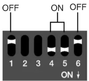
35Mbps/9Mbps 50Mbps/12Mbps
Converting IEEE 1394 to SDI
A signal can be input from an HDV/DV device or computer equipped with an IEEE 1394 (i.LINK) connector to the VC-50HD, and converted to SDI for output to a video recorder.

Audio channels 1 and 2 of the HDV/DV will be output to the channels you specify as the SDI output. Refer to "Specifying the audio input/output channels" (p. 27).

Mode settings for converting IEEE 1394 to SDI
For converting HDV/DV to SDI, make the following mode settings.

HDV(1080i)

HDV(720p)/MPEG-2 TS

DV
Using the VC-50HD with the F-1
If the VC-50HD is used with the F-1 (version 2 or later), the output from an SDI device can be captured by the F-1, or be sent from the F-1 to an SDI device.
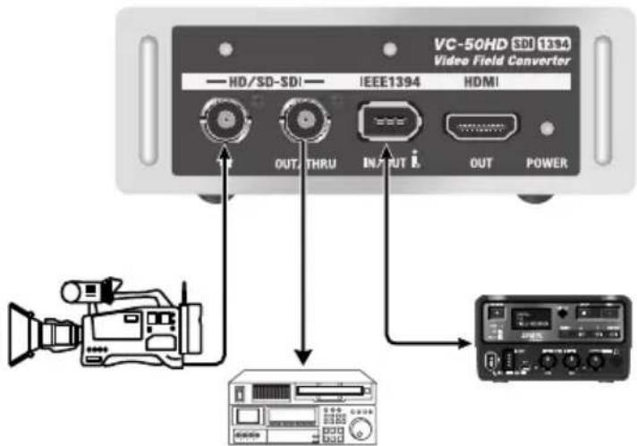
To use the VC-50HD in conjunction with the F-1, make the following setting.

For details about settings on the F-1, refer to the F-1 Version 2 owner's manual section "Using the F-1 with the VC-50HD."

If mode select switch 6 is turned ON so that remote control will be received, operation of the other switches will be disabled.

Even if the VC-50HD is set to receive remote control, the power will not turn on automatically if you're using only the internal AA batteries as the power supply, with nothing connected to the DC IN connector. Use the POWER switch to turn the power on/off.

Even if the VC-50HD is set to receive remote control, the power will not turn on automatically if you're using only the internal AA batteries as the power supply, with nothing connected to the DC IN connector. Use the POWER switch to turn the power on/off.
Connecting Monitors/Mixers
Connecting monitor equipment
The VC-50HD provides an HDMI output connector. You can set up an inexpensive monitoring environment by connecting this to a television or personal computer display equipped with an HDMI input.
* Up/down conversion, I/P conversion, and frame rate conversion are not performed for the HDMI output either.
* The audio channels that are output via HDMI are as follows.
- For HD/SD-SDI input: The channels selected by mode select switches 2/3
•For IEEE 1394 input: Channels 1/2
* Switching the input signal to the VC-50HD while a device remains connected to the HDMI output connector, or frequently connecting or disconnecting a device at the HDMI output connector, may in rare cases result in the picture or audio failing to be output properly, depending on the device connected to the HDMI output connector. If this occurs, reset the power to the VC-50HD or the HDMI device.
* Problems such as faulty contact can also impede correct output of video or audio. Use high-quality HDMI cables.
* The HDMI connector is a precision parts. Handling carefully to prevent contact failure and trouble.

Using the SDI thru-out
If the SDI output of a camera or other device is being input to the VC-50HD and you want the signal to be output to a video mixer or other device in addition to a video recorder, you can use the HD/SD-SDI output/thru-out connector.

By setting the mode select switches located on the VC-50HD's side panel, you can select the audio channels that will be output, and allow remote control from a computer.
Specifying the audio input/output channels
For the SDI embedded audio, only the two specific channels you select will be input and output. Make settings as follows to specify the channels that will be input and output.
* The VC-50HD does not support HDV/DV four-channel audio. If four-channel audio is input, only the two channels 1/2 will be selected.
Selecting which two SDI audio channels go into IEEE 1394
Make the following settings to determine which two channels will go to IEEE 1394.
* If SDI is the source, turn switch 1 to OFF.

Selecting where your two IEEE 1394 audio channels will be encoded to SDI
Make the following settings to determine which two channels will go to SDI.
* If IEEE 1394 is the source, turn switch 1 to ON.

Accepting remote control
The VC-50HD can be remotely controlled by a computer connected to its USB connector or by an F-1 (version 2 or later) connected to its IEEE 1394 connector. Mode settings can be switched via remote control. If you want the VC-50HD to accept remote control, make the following settings.

With this setting, the VC-50HD can receive remote control commands from a computer connected to the USB connector.
For more about remote control software, please refer to the following Roland website. http://www.rolandsystemsgroup.net/

If the VC-50HD is set to accept remote control, its POWER screen will not operate. The power will turn on/off in response to remote control from the external device, or when you disconnect the power cable.

If mode select switch 6 is turned ON so that remote control will be received, the operation of the other switches will be disabled.

Even if the VC-50HD is set to receive remote control, the power will not turn on automatically if you're using only the internal AA batteries as the power supply, with nothing connected to the DC IN connector. Use the POWER switch to turn the power on/off.
Troubleshooting
If you suspect a malfunction, please check the following points before you contact us. If this does not solve the problem, please contact a Roland customer service center.
Can't turn off the power
- Could mode select switch 6 be turned ON? If this is ON, the power will turn off when you disconnect the power cable supply (p. 28).
Power turns on even though you don't operate the POWER switch
- Could mode select switch 6 be turned ON? If this is ON, the power will turn on when you connect the power supply cable (p. 28).
Can't output to computer / Can't input from computer
- Check the setting of mode select switch 5. You must set this OFF if you're using an HDV connection, or ON if you're using a DV connection (p.22, 24).
- After changing the mode setting, you must either reconnect the IEEE 1394 cable or power-cycle the VC-50HD.
- Restart the software you're using, or restart your computer.
- The Roland website listed below contains a continuously-updated list of nonlinear editing software that has been verified to work with material captured via the VC-50HD.
http://www.rolandsystemsgroup.net/
Timecode is not output to your HDV/DV device
- Does the connected HDV/DV device support timecode input via IEEE 1394? If not, it won't be able to record the timecode that's being output from the VC-50HD.
- For details on timecode support, refer to the owner's manual of the connected HDV/DV device.
HDMI output is not shown in the screen
- If the connected HDMI device does not support the signal format being output by the source device, nothing will be displayed on the HDMI device.
* The VC-50HD does not detect the formats supported by an HDMI device, nor does it convert to a supported format. - For details on supported formats, refer to the owner's manual of the connected HDMI device.
Main Specifications
| Video Input | Connectors | ||
| IEEE 1394(i.LINK) | IEEE 1394 (i.LINK) | 6 pin type x 1IEEE 1394-1995(S100)Conforms to HDV/DV standards | |
| HDVDVMPEG-2 TS | 1080/59.94i, 1080/50i, 720/59.94p, 720/50p480/59.94i(NTSC), 576/50i(PAL)1080/59.94i, 1080/50i, 720/59.94p, 720/50p480/59.94i(NTSC), 576/50i(PAL) | HD/SD-SDIInput | BNC type x 1Conforms to SMPTE 259M-C, SMPTE 292M |
| SDI (HD/SD : SMPTE 259M-C, SMPTE 292M) | |||
| HD-SDISD-SDI | 1080/59.94i, 1080/50i(SMPTE 274M)720/59.94p, 720/50p(SMPTE 296M)480/59.94i(NTSC), 576/50i(PAL)(ITU-R BT.656-4) | HD/SD-SDIOut/Thru Out | BNC type x 1Conforms to SMPTE 259M-C, SMPTE 292M |
| HDMIOutput | TYPE A (19 pin) x 1 | ||
| Video Output | |||
| IEEE 1394(i.LINK) | USB | B type x 1Supports USB1.1 Full Speed | |
| HDVDVMPEG-2 TS | 1080/59.94i, 1080/50i, 720/59.94p, 720/50p480/59.94i(NTSC), 576/50i(PAL)1080/59.94i, 1080/50i , 720/59.94p, 720/50p480/59.94i(NTSC), 576/50i(PAL) | DC IN | XLR 4 pin type x 1 |
| SDI (HD/SD : SMPTE 259M-C, SMPTE 292M) | Power Supply | ||
| HD-SDISD-SDI | 1080/59.94i, 1080/50i(SMPTE 274M)720/59.94p, 720/50p(SMPTE 296M)480/59.94i(NTSC), 576/50i(PAL)(ITU-R BT. 656-4) | AC adaptor (PSB-1U), External Battery (DC 9-20V)or AA Batteries (Nickel Hydride or Alkaline) x 8 | |
| Max Operation Time | |||
| HDMI | Approx 2 hours : Nickel Hydride BatteriesApprox 30 minutes : Alkaline BatteriesApprox 10 hours : External Battery(IDX ENDURA-10 Li-Ion Battery)* These operation times are approximate.Actual time may vary somewhat. | ||
| 1080/59.94i, 1080/50i, 720/59.94p, 720/50p, 480/59.94i, 576/50i | |||
| Audio Input | |||
| IEEE 1394(i.LINK) | |||
| HDVDVMPEG-2 TS | MPEG-1 Audio Layer2, 16bit/48kHz, 2ch, 384kbpsLinear PCM, 16bit/48kHz, 2chMPEG-1 Audio Layer2, 16bit/48kHz, 2ch, 384kbps | ||
| SDI (HD/SD : Embedded Audio) | Current Draw | ||
| HD-SDISD-SDI | Linear PCM, 24bit/48kHz, 2ch (SMPTE 299M)Linear PCM, 24bit/48kHz, 2ch (SMPTE 272M-AC) | 2000mA | |
| Dimensions | |||
| Audio Output | 114(W) x 194(D) x 42(H) mm1-1/2(W) x 7-11/16(D) x 1-11/16(H) inches | ||
| IEEE 1394(i.LINK) | Weight | ||
| HDVDVMPEG-2 TS | MPEG-1 Audio Layer2, 16bit/48kHz, 2ch, 384kbpsLinear PCM, 16bit/48kHz, 2chMPEG-1 Audio Layer2, 16bit/48kHz, 2ch, 384kbps | 620g1 lb 6 oz (excluding batteries) | |
| Operation Temperature | |||
| SDI (HD/SD : Embedded Audio) | 0 to +40 degrees Celsius+32 to +104 degrees Fahrenheit | ||
| HD-SDISD-SDI | Linear PCM, 24bit/48kHz, 2ch (SMPTE 299M)Linear PCM, 24bit/48kHz, 2ch (SMPTE 272M-AC) | Accessories | |
| HDMI | Owner's Manual,AC Adaptor (PSB-1U),Power Cable,Conversion Cable (AC adaptor to XLR 4 pins),Battery Case,Battery Plate Holder,Fastening Screws x 8 for Battery Plate Holder,Ferrite Core x 6 | ||
| Linear PCM, 24bit/48kHz, 2ch | |||
| Timecode Input/Output | |||
| IEEE 1394(i.LINK) | |||
| HDVDVMPEG-2 TS | Conforms to HDV standardsConforms to IEC 61834-2Conforms to IEC 13818-2 | ||
| SDI (HD/SD) | |||
| HD-SDISD-SDI | Conforms to SMPTE RP188(VITC, LTC)Conforms to SMPTE 266M(DVITC), RP188(VITC, LTC) | ||
* In the iinterest of product improvement, the specifications and/or appearances of this unit are subject to change without prior notice..
Dimensions

Block Diagram

flowchart
graph TD
    A["HD/SD-SDI IN"] --> B["SDI RX"]
    B --> C["ENCODE / DECODE"]
    C --> D["CONVERT"]
    D --> E["IEEE 1394"]
    C --> F["SPLIT"]
    F --> G["SDI TX"]
    F --> H["HDMI TX"]
    G --> I["HD/SD-SDI OUT/THRU"]
    H --> J["HDMI OUT"]
Timecode
• Supported timecode
See "Main specifications" (p. 30)
• TC input priority order
VITC and LTC ancillary timecode (SMPTE RP 188) is supported for HD-SDI.
For SD-SDI, digital timecode (SMPTE 266M DVITC) is also supported in addition to the above two.
Since only one of these timecodes can converted into the output signal from the IEEE 1394 connector, they are used in the following priority order.
For HD-SDI (1080i/720p)
SMPTE RP 188 VITC is detected > use SMPTE RP 188 VITC
>
(undetected)
>
SMPTE RP 188 LTC is detected > use SMPTE RP 188 LTC
>
(undetected)
>
Use free-run of internal timecode generator
For SD-SDI (480i/576i)
SMPTE 266M DVITC is detected > use SMPTE 266M DVITC
>
(undetected)
>
SMPTE RP 188 VITC is detected > use SMPTE RP 188 VITC
>
(undetected)
>
SMPTE RP 188 LTC is detected > use SMPTE RP 188 LTC
>
(undetected)
>
Use free-run of Internal timecode generator
* If the input signal is 1080/59.94i, 720/59.94p, or 480/59.94i, the internal timecode generator will be drop-frame.
• DVITC insertion lines
NTSC: 16, 18 PAL: 11, 13
Memo
For EU Countries

UK This symbol indicates that in EU countries, this product must be collected separately from household waste, as defined in each region. Products bearing this symbol must not be discarded together with household waste.
This equipment has been tested and found to comply with the limits for a Class B digital device, pursuant to Part 15 of the FCC Rules. These limits are designed to provide reasonable protection against harmful interference in a residential installation. This equipment generates, uses, and can radiate radio frequency energy and, if not installed and used in accordance with the instructions, may cause harmful interference to radio communications. However, there is no guarantee that interference will not occur in a particular installation. If this equipment does cause harmful interference to radio or television reception, which can be determined by turning the equipment off and on, the user is encouraged to try to correct the interference by one or more of the following measures:
- Reorient or relocate the receiving antenna.
- Increase the separation between the equipment and receiver.
- Connect the equipment into an outlet on a circuit different from that to which the receiver is connected.
- Consult the dealer or an experienced radio/TV technician for help.
This device complies with Part 15 of the FCC Rules. Operation is subject to the following two conditions:
(1) this device may not cause harmful interference, and
(2) this device must accept any interference received, including interference that may cause undesired operation.
Unauthorized changes or modification to this system can void the users authority to operate this equipment. This equipment requires shielded interface cables in order to meet FCC class B Limit.
For Canada
NOTICE
This Class B digital apparatus meets all requirements of the Canadian Interference-Causing Equipment Regulations.
AVIS
This product contains chemicals known to cause cancer, birth defects and other reproductive harm, including lead.
For the USA
DECLARATION OF CONFORMITY Compliance Information Statement
Model Name : VC-50HD
Type of Equipment : Converter
Responsible Party : Roland Systems Group U.S.
Address: 801 West Orchard Drive, Suite 3, Bellingham, WA, 98225 U.S.A
Telephone : (360) 594-4282
- INSTRUCTIONS FOR THE PREVENTION OF FIRE, ELECTRIC SHOCK, OR INJURY TO PERSONS
- ALWAYS OBSERVE THE FOLLOWING
- ! WARNING
- WARNING
- CAUTION
- Power Supply: Use of Batteries
- Placement
- Maintenance
- Repairs and Data
- Additional Precautions
- Copyright
- Check the included items
- The VC-50HD itself
- Battery case
- AC adaptor and power cable
- Adaptor cable (AC adaptor to XLR 4-pin connector)
- Battery plate holder and fastening screws (8 pcs.)
- Ferrite cores (6 pcs.)
- Owner's manual (this document)
- Conversion between HD/SD-SDI and HDV/DV
- High-quality conversion of MPEG-2 TS (35 Mbps/50 Mbps)
- Three-way power supply support
- Compact and tough body
- Provides a low-cost monitoring environment
- The VC-50HD's conversion capabilities
- Names of things and what they do
- Front panel
- HD/SD-SDI input connector and indicator
- HD/SD-SDI output/thru out connector
- IEEE 1394 connector and indicator
- HDMI output connector
- POWER indicator
- Side panel
- USB connector
- Mode select switches
- POWER switch
- DC IN connector
- Placement and connections
- Cooling vents
- Theft prevention lock
- Connection cables
- Ferrite cores
- Cable quality
- Power supply
- Connecting the AC adaptor
- Connect the adaptor cable to the AC adaptor
- Connect the AC adaptor to the VC-50HD
- Installing AA batteries
- Install eight AA batteries in the battery case
- Remove the rear cover
- Insert the battery case into the VC-50HD
- Close the rear cover
- Caution regarding batteries
- Continuous use of AA batteries
- Attaching an external battery
- Attach the battery plate (sold separately) to the included holder
- Remove the screws from the top surface of the VC-50HD.
- 3.Fasten the battery plate and holder to the top of the VC-50HD
- Attach the external battery
- NOTE
- Regarding the external battery
- Turning the power on
- Turning the power off
- Caution regarding the power supply
- Connections with video devices
- Converting SDI to IEEE 1394
- Mode settings to output HDV
- Mode settings to output DV
- Mode settings to output MPEG-2 TS
- Converting IEEE 1394 to SDI
- Mode settings for converting IEEE 1394 to SDI
- Using the VC-50HD with the F-1
- Connecting Monitors/Mixers
- Connecting monitor equipment
- Using the SDI thru-out
- Specifying the audio input/output channels
- Selecting which two SDI audio channels go into IEEE 1394
- Selecting where your two IEEE 1394 audio channels will be encoded to SDI
- Accepting remote control
- Troubleshooting
- Can't turn off the power
- Power turns on even though you don't operate the POWER switch
- Can't output to computer / Can't input from computer
- Timecode is not output to your HDV/DV device
- HDMI output is not shown in the screen
- Dimensions
- Block Diagram
- Timecode
- Memo
- For EU Countries
- NOTICE
- AVIS
- DECLARATION OF CONFORMITY Compliance Information Statement
Brand : ROLAND
Model : VC-50HD
Category : Video Converter