
SM-DVN-84X - KVM switch Smart-AVI - Free user manual and instructions
Find the device manual for free SM-DVN-84X Smart-AVI in PDF.


| Product Type | KVM Switch |
| Model Number | SM-DVN-84X |
| Brand | Smart-AVI |
| Connections | 8 DVI-D video inputs, 8 USB Type-B inputs, 1 DVI-D output, 2 USB Type-A console ports, 3.5mm audio |
| Supported Computers | Up to 8 computers |
| Video Resolution | Up to 1920 x 1200 @ 60Hz |
| Control Methods | Front panel push buttons, keyboard hotkeys, RS-232 |
| Power Supply | DC 5V, 2A power adapter (included) |
| Dimensions (W x D x H) | 17.0 x 4.3 x 1.7 inches (432 x 110 x 44 mm) |
| Weight | 2.6 lbs (1.2 kg) |
| Operating Temperature | 32°F to 104°F (0°C to 40°C) |
| Storage Temperature | -4°F to 140°F (-20°C to 60°C) |
| Humidity | 0% – 80% RH, non-condensing |
| LED Indicators | Power, active port |
| Cable Length | Up to 15 ft recommended per KVM cable |
| Keyboard/Mouse Emulation | USB HID emulation for seamless switching |
| Audio Support | Separate 3.5mm microphone and speaker jacks |
| Maintenance | Clean with a soft, dry cloth; do not use liquids |
| Safety | Keep away from moisture and direct sunlight; use only provided power adapter |
| Spare Parts | No user-serviceable parts; contact support for replacements |
| Warranty | 2 years limited warranty |
Frequently Asked Questions - SM-DVN-84X Smart-AVI
User questions about SM-DVN-84X Smart-AVI
0 question about this device. Answer the ones you know or ask your own.
Ask a new question about this device
Download the instructions for your KVM switch in PDF format for free! Find your manual SM-DVN-84X - Smart-AVI and take your electronic device back in hand. On this page are published all the documents necessary for the use of your device. SM-DVN-84X by Smart-AVI.
USER MANUAL SM-DVN-84X Smart-AVI
| SM-DVN-44X | 4-Port DVI-D KVM Matrix, 4 Users |
| SM-DVN-82X | 8-Port DVI-D KVM Matrix, 2 Users |
| SM-DVN-84X | 8-Port DVI-D KVM Matrix, 4 Users |
TABLE OF CONTENTS
TECHNICAL SPECIFICATIONS 3
WHAT'S IN THE BOX? 4
SM-DVN FRONT AND REAR 4
INSTALLATION 5-8
LED's BEHAVIOR 11
SYSTEM OPERATION 12
TROUBLESHOOTING 12
TECHNICAL SUPPORT 12
LIMITED WARRANTY STATEMENT 13
TECHNICAL SPECIFICATIONS
| VIDEO | ||
| Format DVI-I Dual Link | ||
| Host Interface | SM-DVN-44X | (4) DVI-I 29-pin (female) / DVI-D |
| SM-DVN-82X / SM-DVN-84X | (8) DVI-I 29-pin (female) / DVI-D | |
| User Console Interface | SM-DVN-82X | (2) DVI-I 29-pin (female) / DVI-D |
| SM-DVN-44X / SM-DVN-84X | (4) DVI-I 29-pin (female) / DVI-D | |
| Max Resolution | 2560 x 1600 @ 60Hz; 3840x2160 @ 30Hz (w/HDMI-to-DVI adapter) | |
| DDC 5 volts p-p (TTL) | ||
| Input Equalization Automatic | ||
| Input Cable Length Up to | 20 ft. | |
| Output Cable Length Up to | 20 ft. | |
| USB | ||
| Signal Type | USB 2.0, 1.1, and 1.0 w/ internal hub | |
| Type A to B | SM-DVN-44X | (4) |
| SM-DVN-82X / SM-DVN-84X | (8) | |
| User Console Interface | (2) USB Type-A for keyboard and mouse connection only | |
| AUDIO | ||
| Input (4) / (8) Connector Stereo 3.5mm Female | ||
| Output (2) / (4) Connector Stereo 3.5mm Female | ||
| CONTROL | ||
| Front Panel | Push Buttons with LED indicators | |
| RS232 | Via Serial @ 115200 bps | |
| Hot Keys | Via Keyboard | |
| POWER | ||
| Power Requirements | 12V DC, 3A (minimum) power adapter with center-pin positive polarity. | |
| ENVIRONMENT | ||
| Operating Temp | 32° to 104° F (0° to 40° C) | |
| Storage Temp | -4° to 140° F (-20° to 60° C) | |
| Humidity | 0-80% RH, non-condensing | |
| OTHER | ||
| Emulation | Keyboard, Mouse and Video | |
| Control | Front Panel Buttons | |
WHAT'S IN THE BOX?
| SM-DVN Unit | 4/8-port DVI-D Matrix KVM |
| PS12VDC3A | 12V DC, 3A (minimum) power adapter with center-pin positive polarity. |
| User Manual |
SM-DVN-84X REAR

natural_image
Back view of a black electronic device rack with multiple ports and connectors (no visible text or labels)SM-DVN-84X FRONT

SM-DVN-44X REAR
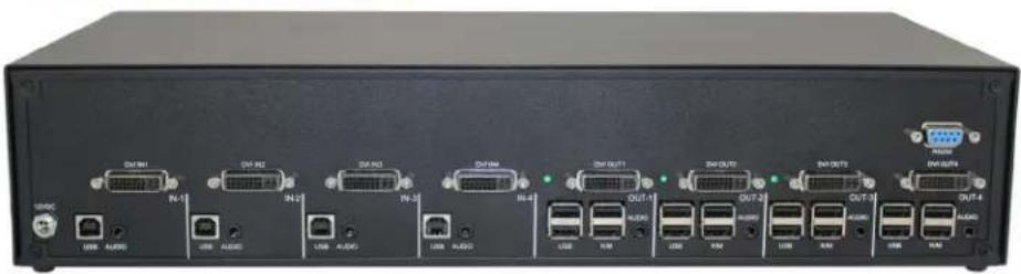
natural_image
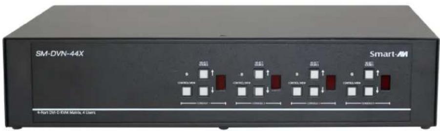
Back view of a black electronic device rack with multiple ports and connectors (no visible text or labels)SM-DVN-44X FRONT
INSTALLATION
- Ensure that power is turned off or disconnected from the unit and the computers.
- Use a DVI cable to connect the DVI output port from each computer to the corresponding DVI-D IN ports of the unit.
- Use a USB cable (Type-A to Type-B) to connect a USB port on each computer to the respective USB ports of the unit.
- Optionally, connect a stereo audio cable (3.5mm to 3.5mm) to the audio output of each computer to the AUDIO IN ports of the unit.
- For each user, connect a monitor to each DVI-D OUT console port of the unit using DVI cables.
- For each user, connect a USB keyboard and mouse to the two USB console ports.
- Optionally, for each user, connect stereo speakers to the AUDIO OUT ports of the unit.
- Finally, power on the KVM by connecting a 12VDC power supply to the power connector, and then turn on all the computers.
Note: You can connect up to 8 computers to the 8 port KVM and up to 4 computers to the 4 port KVM.

flowchart
graph TD
    A["Computer"] -->|USB 2.0 OUT| B["Switch"]
    A -->|USB IN| C["Server"]
    A -->|DVI IN| D["Computer"]
    A -->|DVI OUT| E["Switch"]
    A -->|AUDIO IN| F["Computer"]
    A -->|AUDIO OUT| G["Switch"]
    H["Computer"] -->|USB K/M OUT| I["Switch"]
    H -->|USB IN| J["Server"]
    H -->|DVI IN| K["Switch"]
    H -->|DVI OUT| L["Computer"]
SM-DVN-44X Shown
INSTALLATION (CONTINUED)

flowchart
graph TD
    A["Server 1"] --> B["Server 2"]
    B --> C["Server 3"]
    C --> D["Server 4"]
    D --> E["Server 5"]
    E --> F["Server 6"]
    F --> G["Server 7"]
    G --> H["Server 8"]
    H --> I["Server 9"]
    I --> J["Server 10"]
    J --> K["Server 11"]
    K --> L["Server 12"]
    L --> M["Server 13"]
    M --> N["Server 14"]
    N --> O["Server 15"]
    O --> P["Server 16"]
    P --> Q["Server 17"]
    Q --> R["Server 18"]
    R --> S["Server 19"]
    S --> T["Server 20"]
    T --> U["Server 21"]
    U --> V["Server 22"]
    V --> W["Server 23"]
    W --> X["Server 24"]
    X --> Y["Server 25"]
    Y --> Z["Server 26"]
    Z --> AA["Server 27"]
    AA --> AB["Server 28"]
    AB --> AC["Server 29"]
    AC --> AD["Server 30"]
    AD --> AE["Server 31"]
    AE --> AF["Server 32"]
    AF --> AG["Server 33"]
    AG --> AH["Server 34"]
    AH --> AI["Server 35"]
    AI --> AJ["Server 36"]
    AJ --> AK["Server 37"]
    AK --> AL["Server 38"]
    AL --> AM["Server 39"]
    AM --> AN["Server 40"]
    AN --> AO["Server 41"]
    AO --> AP["Server 42"]
    AP --> AQ["Server 43"]
    AQ --> AR["Server 44"]
    AR --> AS["Server 45"]
    AS --> AT["Server 46"]
    AT --> AU["Server 47"]
    AU --> AV["Server 48"]
    AV --> AW["Server 49"]
    AW --> AX["Server 50"]
SM-DVN-84X Shown
INSTALLATION (CONTINUED)
EDID Learn:
The KVM is designed to learn the connected monitor's EDID upon power up. In the event of connecting a new monitor to the KVM, a power recycle is required.
The KVM will indicate to the user that the EDID learn process is ongoing by flashing the LED next to DVI OUT port 1. When the LEDs stop flashing, the EDID learn process is done.
The monitor must be connected to the video output connector located in the console space at the back of the KVM during the EDID learn process.
If the read EDID from the connected monitor is identical to the current stored EDID in the KVM then the EDID learn function will be skipped unless the force learn EDID process is used. To force learn the EDID, hold down the First and Last CAC buttons of Front Panel for 3 seconds to force Learn

SYSTEM OPERATION
There are three ways to control the SM-DVN: Keyboard Hotkeys, RS-232 Serial Commands, and Front Panel Buttons. All modes of control will allow the user to set their desired configurations.
FRONT PANEL CONTROL
To switch to an input port for a given console, push the UP or DOWN buttons as many times as needed to navigate to the desired channel. The channel number indicator will display to selected channel for each console.
By default, the unit will start in View Mode, indicated by a red LED above the CAC button on the front panel. In View Mode, keyboard and mouse functionality are disabled. Control Mode enables full keyboard and mouse functionality.
HOTKEY AND RS232 SERIAL CONTROL
The SM-DVN may also be controlled via RS-232 commands. To use these commands, you must use HyperTerminal or an alternative terminal application. The settings for the connection are as follows: Baudrate 115200; Data Bits 8; Parity None; Stop Bits 1; Flow Control None.
Once you have connected to the SM-DVN via Serial, you will see the SM-DVN information when the device starts up.
The following commands can be used for RS-232 with available keyboard hotkeys:
| Command Description | HotKey | RS-232 Command |
| Switch all USB devices and Main video | [CTRL] [CTRL] c [port #] [ENTER] | //c [user #] [port #] [ENTER] |
| Switch Channel View Only | [CTRL] [CTRL] v [port #] [ENTER] | //v [user #] [port #] [ENTER] |
| Learn EDID | [CTRL] [CTRL] e [ENTER] | //e [ENTER] |
| Trigger Hotplug | [CTRL] [CTRL] h [ENTER] | //h [ENTER] |
| Reset Software | [CTRL] [CTRL] r [ENTER] | //r [ENTER] |
| View Current Hotkey | N/A | //hk [ENTER] |
CUSTOM HOTKEY TRIGGERS
Users are able to customize the keys that trigger Hotkeys. The default trigger for hot key function on the Keyboard is Ctrl +Ctrl. The trigger function can be used to change to double Ctrl, Shift, or Scroll Lock.
To view hotkey trigger setting:
Type on Keyboard: Alt + Alt + Alt + k + 0 + [Enter]
The LED Light on the user's keyboard will Flash indicating which trigger is currently active
Num Lock LED flash indicates CTRL
Caps Lock LED flash indicates Shift
Scroll Lock LED flash indicates Scroll Lock
To change the hotkey trigger setting:
Hotkey trigger twice + x + [1 | 2 | 3]
1 - Ctrl
2 - Shift
3 - Scroll Lock
Example: If the hotkey trigger is Shift and would like to change to Scroll Lock,
Type: Shift + Shift + x + 3
LED'S BEHAVIOR
User Console Interface – Display LED:
| # | Status Description | |
| 1 | Off | Monitor is not connected |
| 2 | On Monitor is connected | |
| 3 | Flashing (back panel) | EDID problem – Learn EDID to fix the problem |
Front Panel – Port Selection LED's:
| # Status Description | |
| 1 Red View Mode | |
| 2 Green Control Mode |
EDID Learn - Front Panel LED's:
All LED's are turned on for 1 second. Then:
- Port 1 LED's will flash until the end of the process.
SYSTEM OPERATION
Front Panel Control
Below is a list of commands sent through button presses on the front panel. Refer to diagram below for the names of buttons:
- Press CAC button - Toggle between Control and View mode
- Press UP button - Increment current channel, loop back to 1 after ch. 8
- Press DOWN button - Decrement current channel, loop back to 8 after ch. 1
- Press and hold the CAC button, then press the UP button - enables CAC mode only when user is already in control mode
- Press and hold the CAC button, then press the DOWN button - disables the display and KM control for that user.

Close-up of the Front Panel controls for the matrix series.
TROUBLESHOOTING
No Power
- Make sure that the power adapter is securely connected to the power connector of the unit.
- Check the output voltage of the power supply and make sure that the voltage value is around 12VDC.
- Replace the power supply.
No Video
- Check if all the video cables are connected properly.
- Connect the computer directly to the monitor to verify that your monitor and computer are functioning properly.
- Restart the computers
Keyboard is not working
- Check if the keyboard is properly connected to the unit.
- Check if the USB cables connecting the unit and the computers are properly connected.
- Try connecting the USB on the computer to a different port.
- Make sure that the keyboard works when directly connected to the computer.
- Replace the keyboard.
Mouse is not working
- Check if the mouse is properly connected to the unit.
- Try connecting the USB on the computer to a different port.
- Make sure that the mouse works when directly connected to the computer.
- Replace the mouse.
No Audio
- Check if all the audio cables are connected properly.
- Connect the speakers directly to the computer to verify that the speakers and the computer audio are functioning properly.
- Check the audio settings of the computer and verify that the audio output is through the speakers.
TECHNICAL SUPPORT
For product inquiries, warranty questions, or technical questions, please contact info@smartavi.com.
LIMITED WARRANTY STATEMENT
A. Extent of limited warranty
SmartAVI, Inc. warrants to the end-user customers that the SmartAVI product specified above will be free from defects in materials and workmanship for the duration of 1 year, which duration begins on the date of purchase by the customer. Customer is responsible for maintaining proof of date of purchase.
SmartAVI limited warranty covers only those defects which arise as a result of normal use of the product, and do not apply to any:
a. Improper or inadequate maintenance or modifications
b. Operations outside product specifications
c. Mechanical abuse and exposure to severe conditions
If SmartAVI receives, during applicable warranty period, a notice of defect, SmartAVI will at its discretion replace or repair defective product. If SmartAVI is unable to replace or repair defective product covered by the SmartAVI warranty within reasonable period of time, SmartAVI shall refund the cost of the product.
SmartAVI shall have no obligation to repair, replace or refund unit until customer returns defective product to SmartAVI.
Any replacement product could be new or like new, provided that it has functionality at least equal to that of the product being replaced.
SmartAVI limited warranty is valid in any country where the covered product is distributed by SmartAVI.
B. Limitations of warranty
To the extant allowed by local law, neither SmartAVI nor its third party suppliers make any other warranty or condition of any kind whether expressed or implied with respect to the SmartAVI product, and specifically disclaim implied warranties or conditions of merchantability, satisfactory quality, and fitness for a particular purpose.
C. Limitations of liability
To the extent allowed by local law the remedies provided in this warranty statement are the customers sole and exclusive remedies.
To the extant allowed by local law, except for the obligations specifically set forth in this warranty statement, in no event will SmartAVI or its third party suppliers be liable for direct, indirect, special, incidental, or consequential damages whether based on contract, tort or any other legal theory and whether advised of the possibility of such damages.
D. Local law
To the extent that this warranty statement is inconsistent with local law, this warranty statement shall be considered modified to be consistent with such law.
Smart-AM
SMART AUDIO VIDEO INNOVATION
NOTICE
The information contained in this document is subject to change without notice. SmartAVI makes no warranty of any kind with regard to this material, including but not limited to, implied warranties of merchantability and fitness for particular purpose. SmartAVI will not be liable for errors contained herein or for incidental or consequential damages in connection with the furnishing, performance or use of this material. No part of this document may be photocopied, reproduced, or translated into another language without prior written consent from SmartAVI, Inc.
20180109

Designed and Manufactured in the USA
Tel: (800) AVI-2131 • (702) 800-0005
2455 W Cheyenne Ave, Suite 112
North Las Vegas, NV 89032
www.smartavi.com


- TABLE OF CONTENTS
- WHAT'S IN THE BOX?
- SM-DVN-84X REAR
- SM-DVN-84X FRONT
- SM-DVN-44X REAR
- SM-DVN-44X FRONT
- INSTALLATION
- INSTALLATION (CONTINUED)
- EDID Learn:
- SYSTEM OPERATION
- FRONT PANEL CONTROL
- HOTKEY AND RS232 SERIAL CONTROL
- CUSTOM HOTKEY TRIGGERS
- To view hotkey trigger setting:
- To change the hotkey trigger setting:
- LED'S BEHAVIOR
- TROUBLESHOOTING
- No Power
- No Video
- Keyboard is not working
- Mouse is not working
- No Audio
- TECHNICAL SUPPORT
- LIMITED WARRANTY STATEMENT
- Extent of limited warranty
- Limitations of warranty
- Limitations of liability
- Local law
- Smart-AM
- SMART AUDIO VIDEO INNOVATION
- NOTICE
Brand : Smart-AVI
Model : SM-DVN-84X
Category : KVM switch