
676R - AV Switch Kramer - Free user manual and instructions
Find the device manual for free 676R Kramer in PDF.


| Product Type | AV Switch / Switcher |
| Model | Kramer 676R |
| Brand | Kramer Electronics |
| Category | Audio/Video Switcher |
| Form Factor | Rack-mountable, 1U |
| Dimensions (W x D x H) | 19 x 10 x 1.75 inches (typical) |
| Weight | Approximately 3.5 lb (1.6 kg) |
| Power Supply | 110-240V AC, 50/60 Hz, internal or external adapter |
| Power Consumption | 5W max |
| Inputs | Multiple composite video / stereo audio (RCA) |
| Outputs | 1 composite video + stereo audio (RCA) |
| Control | Front panel buttons, RS-232 (optional) |
| Bandwidth | 100 MHz (-3dB) typical |
| Video Format | NTSC, PAL, SECAM compatible |
| Audio Impedance | 50 kOhm (input), 1 kOhm (output) |
| Cleaning Instructions | Wipe with a soft, dry cloth; do not use liquids or solvents |
| Safety | Use only with provided power supply; avoid moisture |
| Spare Parts & Repairability | Contact Kramer support for parts; no user-serviceable parts inside |
| General Information | Designed for professional AV switching; suitable for home theater or broadcast |
Frequently Asked Questions - 676R Kramer
User questions about 676R Kramer
0 question about this device. Answer the ones you know or ask your own.
Ask a new question about this device
Download the instructions for your AV Switch in PDF format for free! Find your manual 676R - Kramer and take your electronic device back in hand. On this page are published all the documents necessary for the use of your device. 676R by Kramer.
USER MANUAL 676R Kramer

Scan for full manual
676T / 676R Quick Start Guide
This guide helps you install and use your 676T / 676R for the first time.
Go to www.kramerav.com/downloads/676T or www.kramerav.com/downloads/676R to download the latest user manual and check if firmware upgrades are available.
Step 1: Check what's in the box
676T HDMI Optical Transmitter or 676R HDMI Optical Receiver
1 Bracket set
4 Rubber feet
1 Power cord and adapter
1 Quick start guide
1 OSP-MM1 Fiber Optic SFP+ Transceiver
Step 2: Get to know your 676T and 676R

676T can be connected to a single 676R device or to multiple devices via optical splitters. When multiple devices are connected, a receiver device is defined as primary when its Tx (SFP+ OUT) optical fiber is connected directly to the 676T Rx optical fiber (SFP+ IN).
676T

flowchart
graph TD
    1["1"] --> IN["○"]
    2["2"] --> OUT["○"]
    3["3"] --> LINK["Tx"]
    4["4"] --> ON["○"]
    style IN fill:#fff,stroke:#000
    style OUT fill:#fff,stroke:#000
    style LINK fill:#fff,stroke:#000
    style ON fill:#fff,stroke:#000
flowchart
graph TD
    A["5"] --> B["HDMI™ IN"]
    C["6"] --> D["RS-232"]
    E["7"] --> F["OUT IN"]
    G["8"] --> H["SETUP"]
    I["9"] --> J["RESET"]
    K["10"] --> L["SERVICE"]
    M["11"] --> N["12V DC"]
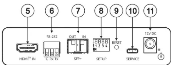
| # | Feature | Function | |
| 1 | IN LED | Lights green when a connected source device (with an active HDMITM signal) is detected. Flashes 4 times green when resetting the device. Off when no active signal is detected on the connected HDMI source device. | |
| 2 | OUT LED | Lights green when an HDMI acceptor device (with an active HDMI signal) is detected. Off when no active signal is detected on the connected acceptor. | |
| 3 | LINK LEDs | Tx | Lights green when OUT IN SFP+ is connected, and an active Tx optical link is detected. Lights red when OUT IN SFP+ is connected, and a fault is detected on the single/primary 676R receiving optical link. Off when the OUT IN SFP+ is disconnected. |
| Rx | Lights green when OUT IN SFP+ is connected, and an active Rx optical link is detected. Lights red when OUT IN SFP+ is connected, and a fault is detected on the incoming optical link. Off when OUT IN SFP+ is disconnected. | ||
| 4 | ON LED | Lights green when the device receives power. | |
| 5 | HDMITM IN Connector | Connect to an HDMI source. | |
| 6 | RS-232 (Tx, Tr, G) 3-pin Terminal Block Connector | Connect to a serial controller to communicate serially with all the connected receivers. i Receives RS-232 communication only from a single/primary receiver. | |
| 7 | OUT IN SFP+ Connector | Connect the fiber optic cable to the plugged-in SFP+ optical module connectors. (OSP-MM1, included). | |
| 8 | SETUP 4-way DIP-switch | Sets the device behavior. | |
| 9 | RESET Recessed Button | Press and hold for 5 seconds or less to reset the device. Press and hold for over 5 seconds to reset the device to factory default values. | |
| 10 | SERVICE Micro USB Port | Connect to a PC to perform firmware upgrade (via K-Upload). | |
| 11 | 12V DC Power Connector | 12V DC connector for powering the unit. | |
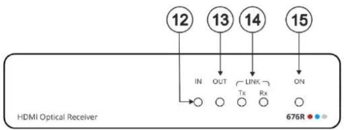

| # | Feature | Function | |
| 12 | IN LED | Lights green when a connected HDMI source device (with an active HDMI signal) is detected.Flashes 4 times green when resetting the device.Off when no active signal is detected on the connected source device. i IN LED is always off for 676R receivers other than the single/primary device. | |
| 13 | OUT LED | Lights green when an HDMI acceptor device (with an active HDMI signal) is detected on the single/primary 676R device.Off when no active signal is detected on the connected acceptor. | |
| 14 | LINK LEDs | Tx | Lights green when OUT IN SFP+ is connected, and an active Tx optical link is detected.Lights red when OUT IN SFP+ is connected, and a fault is detected on the 676T receiving optical link.i Tx LED on devices other than the single/primary 676R device always light red.Off when OUT IN SFP+ is disconnected. |
| Rx | Lights green when OUT IN SFP+ is connected, and an active Rx optical link is detected.Lights red when OUT IN SFP+ is connected, and a fault is detected on the incoming active optical link.Off when OUT IN SFP+ is disconnected. | ||
| 15 | ON LED | Lights green when the device receives power. | |
| 16 | HDMI ^TM OUT Connector | Connect to an HDMI acceptor. | |
| 17 | RS-232 (Tx, Tr, G) 3-pin Terminal Block Connector | Connect to the serial control port of a controlled device located next to the 676R.i Only the controlled device connected to the single/primary receiver returns serial data to the transmitter. | |
| 18 | OUT IN SFP+ Connector | Connect the fiber optic cable to the plugged-in SFP+ optical module connectors (OSP-MM1, Included). | |
| 19 | SERVICE Micro USB Port | Connect to a PC to perform firmware upgrade via K-Upload. | |
| 20 | 12V DC Power Connector | 12V DC connector for powering the unit. | |
Step 3: Mount 676T/676R
Install 676T/676R using one of the following methods:
- Attach the rubber feet and place the unit on a flat surface.
- Fasten a bracket (included) on each side of the unit and attach it to a flat surface (see www.kramerav.com/downloads/676T).
- Mount the unit in a rack using the recommended rack adapter (see www.kramerav.com/product/676T).


- Ensure that the environment (e.g., maximum ambient temperature & air flow) is compatible for the device.
- Avoid uneven mechanical loading.
- Appropriate consideration of equipment nameplate ratings should be used for avoiding overloading of the circuits.
- Reliable earthing of rack-mounted equipment should be maintained.
• Maximum mounting height for the device is 2 meters.
Step 4: Connect inputs and outputs
Always switch OFF the power on each device before connecting it to your 676T/676R.

flowchart
graph TD
    subgraph_676T["676T"]
        A["PC"] --> B["HDMI IN"]
        B --> C["RS-232 G RX TX"]
        C --> D["OUT IN"]
        D --> E["SFP+"]
        E --> F["SETUP"]
        F --> G["RESET"]
        G --> H["SERVICE"]
        H --> I["12V DC +"]
    end

    subgraph_676R["676R"]
        J["Display"] --> K["HDMI OUT"]
        K --> L["RS-232 G RX TX"]
        L --> M["OUT IN"]
        M --> N["SFP+"]
        N --> O["SERVICE"]
        O --> P["12V DC +"]
    end

    A --> Q["SL-240 Controller"]
    C --> R["RS-232"]
    E --> S["RS-232"]
    G --> T["RS-232"]
    I --> U["RS-232"]
    style 676T fill:#f9f,stroke:#333
    style 676R fill:#bbf,stroke:#333

For optimal performance, use the recommended Kramer cables available at www.kramerav.com/product/676T.
Using third-party cables may cause damage!
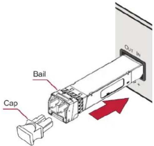
To install/replace the OSP-MM1 or other Kramer recommended SFP+ transceiver:
- Pull the bail out and remove the currently installed transceiver, insert the protective cap and store in a safe place.
- Make sure the bail of the new transceiver is pushed up, in the closed position.
- Insert the new transceiver into the relevant optical device SFP+ slot and push it in until it clicks.
- Remove the protective cap and store it in a safe place for future use.
Warning: Connecting the OSP SFP+ connector to an LC(APC) fiber connector may cause poor performance and damage the connector! Refer to www.kramerav.com/downloads/OSP-MM1 for more information.
Warning: Class 1 Laser Product
• Invisible laser radiation present.
- Avoid long-term viewing of laser.
- Avoid the use of magnifying viewing aids or instruments (such as binoculars, telescopes, microscopes and magnifying lenses, but not spectacles or contact lenses).
- Avoid placing optical devices in the emitted beam that could cause the concentration of the laser radiation to be increased.
Step 5: Connect power
Connect the power cord to 676T/676R and plug it into the mains electricity.

Safety Instructions (See www.kramerav.com for updated safety information)
• There are no operator serviceable parts inside the unit.
Warning:
- Use only the power cord that is supplied with the unit.
- Disconnect the power and unplug the unit from the wall before installing.
- Use only the power cord that is supplied with the unit. - Disconnect the power and unplug the unit from the wall before installing.
Step 6: Operate 676T and 676R
Set the 676T DIP-switches
The DIP-switch setup on 676T applies to all the 676R devices that are connected.
A DIP-switch that is down is on, up is off. Changes to the DIP-switches take effect immediately. By-default, all DIP-switches are set to Off
| # | Function | Status |
| 1 | EDID Lock | Off (up) – Unlock stored EDID.On (down) – Lock stored EDID. |
| 2 | Color Depth | Off (up) – Follow output color depth.On (down) – Force 8-bit color depth. |
| 3 | Input HDCP Appearance | Off (up) – HDCP ON. Always input HDCP-supported appearance.On (down) – HDCP OFF. Always input HDCP-unsupported appearance (MAC mode). |
| 4 | For future use |
Control the devices
Operate remotely, by RS-232 serial commands transmitted by a touch screen system, PC, or other serial controller
| RS-232 Control / Protocol 3000 on the Micro USB | |||
| Baud Rate: | 115,200 | Parity: | None |
| Data Bits: | 8 | Command Format: | ASCII |
| Stop Bits: | 1 | ||
| Example (get device model name): #model? | |||
| Factory Default Parameters | |||
| Reset front panel button: | Press and hold for over 5 seconds to reset the device to factory default settings. | ||
| P3K command: | #factory | ||
The terms HDMI, HDMI High-Definition Multimedia Interface, and the HDMI Logo are trademarks or registered trademarks of HDMI Licensing Administrator, Inc.


- 676T / 676R Quick Start Guide
- Step 1: Check what's in the box
- Step 2: Get to know your 676T and 676R
- Step 3: Mount 676T/676R
- Step 4: Connect inputs and outputs
- To install/replace the OSP-MM1 or other Kramer recommended SFP+ transceiver:
- Warning: Class 1 Laser Product
- Step 5: Connect power
- Step 6: Operate 676T and 676R
- Set the 676T DIP-switches
- Control the devices
Brand : Kramer
Model : 676R
Category : AV Switch