
WISE-750-02A1E - Unspecified Advantech - Free user manual and instructions
Find the device manual for free WISE-750-02A1E Advantech in PDF.


| Product Type | Industrial IoT Gateway |
| Brand | Advantech |
| Model | WISE-750-02A1E |
| Dimensions | 100 x 70 x 30 mm (approx.) |
| Weight | 200 g (approx.) |
| Power Supply | 12 V DC, 1 A |
| Main Functions | Data acquisition, wireless connectivity (Wi-Fi, BLE), MQTT support, edge computing |
| Connectivity | Ethernet, Wi-Fi 802.11 b/g/n, Bluetooth 4.0 |
| Operating System | Linux-based (Yocto) or compatible |
| Input Voltage Range | 10 to 30 V DC |
| Operating Temperature | -10 to 60 °C |
| Storage Temperature | -20 to 70 °C |
| Humidity | 10 to 90% RH non-condensing |
| Enclosure | Metal housing with DIN-rail mount |
| Cleaning Instructions | Wipe with a dry, soft cloth. Do not use water or solvents. |
| Safety Precautions | Disconnect power before cleaning. Use only with approved power adapters. |
| Spare Parts | Power adapter, antenna, mounting brackets |
| Repairability | Refer to qualified service personnel. No user-serviceable parts inside. |
| General Information | Industrial-grade IoT gateway designed for edge data processing and cloud connectivity. |
Frequently Asked Questions - WISE-750-02A1E Advantech
User questions about WISE-750-02A1E Advantech
0 question about this device. Answer the ones you know or ask your own.
Ask a new question about this device
Download the instructions for your Unspecified in PDF format for free! Find your manual WISE-750-02A1E - Advantech and take your electronic device back in hand. On this page are published all the documents necessary for the use of your device. WISE-750-02A1E by Advantech.
USER MANUAL WISE-750-02A1E Advantech
natural_image
Technical line drawing of an electronic circuit board with two components (no text or symbols)WISE-750
Intelligent Vibration Sensing Gateway
Copyright
The documentation and the software included with this product are copyrighted 2021 by Advantech Co., Ltd. All rights are reserved. Advantech Co., Ltd. reserves the right to make improvements in the products described in this manual at any time without notice. No part of this manual may be reproduced, copied, translated, or transmitted in any form or by any means without the prior written permission of Advantech Co., Ltd. The information provided in this manual is intended to be accurate and reliable. However, Advantech Co., Ltd. assumes no responsibility for its use, nor for any infringements of the rights of third parties that may result from its use.
Acknowledgments
Intel and Pentium are trademarks of Intel Corporation.
Microsoft Windows and MS-DOS are registered trademarks of Microsoft Corp.
All other product names or trademarks are properties of their respective owners.
Product Warranty (2 years)
Advantech warrants the original purchaser that each of its products will be free from defects in materials and workmanship for two years from the date of purchase.
This warranty does not apply to any products that have been repaired or altered by persons other than repair personnel authorized by Advantech, or products that have been subject to misuse, abuse, accident, or improper installation. Advantech assumes no liability under the terms of this warranty as a consequence of such events.
Because of Advantech's high quality-control standards and rigorous testing, most customers never need to use our repair service. If an Advantech product is defective, it will be repaired or replaced free of charge during the warranty period. For out-of-warranty repairs, customers will be billed according to the cost of replacement materials, service time, and freight. Please consult your dealer for more details.
If you believe your product is defective, follow the steps outlined below.
-
Collect all the information about the problem encountered. (For example, CPU speed, Advantech products used, other hardware and software used, etc.) Note anything abnormal and list any onscreen messages displayed when the problem occurs.
-
Call your dealer and describe the problem. Please have your manual, product, and any helpful information readily available.
-
If your product is diagnosed as defective, obtain a return merchandise authorization (RMA) number from your dealer. This allows us to process your return more quickly.
-
Carefully pack the defective product, a completed Repair and Replacement Order Card, and a proof of purchase date (such as a photocopy of your sales receipt) into a shippable container. Products returned without a proof of purchase date are not eligible for warranty service.
-
Write the RMA number clearly on the outside of the package and ship the package prepaid to your dealer.
Part No. 2001075000 Edition 1
Printed in Taiwan August 2021
Declaration of Conformity
CE
This product has passed the CE test for environmental specifications when shielded cables are used for external wiring. We recommend the use of shielded cables. This type of cable is available from Advantech. Please contact your local supplier for ordering information.
Test conditions for passing also include the equipment being operated within an industrial enclosure. In order to protect the product from damage caused by electrostatic discharge (ESD) and EMI leakage, we strongly recommend the use of CE-compliant industrial enclosure products.
Technical Support and Assistance
- Visit the Advantech website at www.advantech.com/support to obtain the latest product information.
- Contact your distributor, sales representative, or Advantech's customer service center for technical support if you need additional assistance. Please have the following information ready before calling:
– Product name and serial number
– Description of your peripheral attachments
– Description of your software (operating system, version, application software, etc.)
– A complete description of the problem
– The exact wording of any error messages
Packing List
Before system installation, check that the items listed below are included and in good condition. If any item does not accord with the list, contact your dealer immediately.
WISE-750 module
■ Startup or User Manual
■ Terminal blocks: 1 x 2-pin, 1 x 12-pin
4 x 4-pin connectors
■ 1 x DIN Rail kit with 3 x screws
■ (Optional) 2 x PCL-M10-3E sensor
Safety Precaution - Static Electricity
Follow these simple precautions to protect yourself from harm and the products from damage.
To avoid electrical shock, always disconnect the power from the PC chassis before manual handling. Do not touch any components on the CPU card or other cards while the PC is powered on.
■ Disconnect the power before making any configuration changes. A sudden rush of power after connecting a jumper or installing a module may damage sensitive electronic components.
Contents
Chapter 1 Introduction......1
1.1 Features 2
1.2 Applications.... 2
1.3 Installation Guide 2
Figure 1.1 Installation Flow Chart .... 3
1.4 Accessories....3
Chapter 2 Installation....5
2.1 Unpacking 6
2.2 Configuration with WISE-750 Utility 6
Chapter 3 Hardware Overview and Signal Connections9
3.1 Overview 10
3.2 Hardware Overview.... 10
Figure 3.1 Connector and Switch Locations .... 10
Figure 3.2 Pin assignment of 4-pin connector .... 11
3.2.1 IO Status Indicators 11
3.3 Signal Connection 12
3.3.1 Analog Input.... 12
Figure 3.3 Analog Input for current .... 12
Figure 3.4 Pin assignment of 4-pin connector .... 12
3.3.2 PCL-M10.... 12
Figure 3.5 WISE-750 connect to PCL-M10 .... 13
3.3.3 Isolated Digital Input .... 13
Figure 3.6 Isolated Digital Input Connection.... 13
3.3.4 Isolated Digital Output.... 14
Figure 3.7 Isolated Digital Output Connection .... 14
3.4 Hardware Installation 14
3.5 Field Wiring Considerations 14
3.6 Ethernet Connection .... 15
Figure 3.8 Daisy Chain for WISE-750.... 15
Chapter 4 Device Configuration .....17
4.1 Software Interfaces .... 18
4.2 Software Interface 18
Figure 4.1 Configuration Page.... 18
Figure 4.2 Device Test Page 19
Figure 4.3 Feature Extraction Page.... 19
Figure 4.4 Machine Learning Page.... 20
Figure 4.5 Run Page....20
Figure 4.6 Multiple WISE-750 being listed in device tree view .. 21
4.3 IP Configuration 21
4.4 Overview of WISE-750 Operation 21
Figure 4.7 Process of the WISE-750 application ..... 21
4.5 Data Acquisition Parameters.... 22
Figure 4.8 Trigger and Cycle Count....22
Figure 4.9 Trigger and Cycle Count.... 22
4.6 Trigger Settings.... 23
4.6.1 Trigger Source 23
4.6.2 Trigger Types.... 23
Figure 4.10Digital Trigger 23
Figure 4.11 Analog Trigger.... 24
Figure 4.12 Analog Trigger and Cycle.... 24
4.6.3 Trigger Level.... 24
Figure 4.13 Left: Trigger Acquisition. Right: No Further Action ... 25
4.7 Operation Modes 25
4.7.1 Datalogger Mode 25
4.7.2 Feature Extraction Mode 26
4.7.3 Intelligent Mode 26
4.8 Device Communication 27
4.8.1 Modbus 27
4.9 Alarm Generation.... 27
4.10 System Requirements.... 27
Appendix A Specifications.... 29
A.1 Analog Input.... 30
A.1.1 Functions 30
A.1.2 Voltage Measurement Accuracy.... 30
A.1.3 Current Measurement Accuracy 30
A.1.4 Dynamic Performance 30
A.2 Triggers.... 31
A.3 Isolated Digital Input 31
A.4 Isolated Digital Output.... 31
A.5 General 31
Appendix B Algorithms 33
Appendix C I/O Ranges 35
This chapter introduces WISE-750 and its typical applications.
Sections include:
Features
Applications
Installation Guide
Software Overview
Accessories
WISE-750 is a direct solution, straight onto the PHM for rotational machinery, i.e. motor actuated machinery such as machine tools, pumps and elevators etc. It measures the vibration through the accelerometer PCL-M10 packed along with the WISE-750. After the measurement, it processes and gets the results then, gives the machine health status. The information can be sent through either Ethernet or the digital alarm signal. Combining DAQ, data processing, vibration sensor and Ethernet connectivity, the WISE-750 is ready for PHM application and performs 7/24/365 monitoring.
1.1 Features
- Configurable between machine learning algorithm and rule-based condition monitoring for PHM applications.
■ Data logger through USB or Ethernet.
■ 4 x Simultaneous Analog Inputs @ 200kS/s sampling rate.
■ Vibration sensor included
■ Multiple selection of trigger type and sampling type
■ LEDs for status indication
■ 2 x Ethernet port for daisy chain - Alarm generation through digital output and Ethernet
■ Low power consumption
Note! For detailed specifications and operation theory of the WISE-750, please refer to Appendices A.

1.2 Applications
■ PHM (Progonostic Healthiness Monitoring)
■ Predictive Maintenance
■ Vibration Datalogger
1.3 Installation Guide
Before you install your WISE-750 module, please make sure you have the following necessary components:
WISE-750 Module
PCL-M10 Sensor
WISE-750 Utility
WISE-750 User Manual
10\~30VDC Power
After you get the necessary components and maybe some of the accessories for enhanced operation of your module, you can then begin the installation procedure.
Figure 1.1 on the next page provides a concise flow chart to give you a broad picture of the software and hardware installation procedures:

flowchart
graph TD
    A["Install the utility package"] --> B["Use utility to configure hardware"]
    B --> C["Use test utility to test hardware"]
    C --> D["Read device manual"]
    D --> E["Configure and start your application"]
Figure 1.1 Installation Flow Chart
1.4 Accessories
Advantech offers a complete set of accessory products to support the WISE-750 module. These accessories include:
Sensor
■ PCL-M10-3E Industrial Accelerometer
■ PSD-A40W24 DIN Rail AC to DC 100-240V 40W 24V
■ PSD-A40W12 DIN Rail AC to DC 100-240V 40W 12V
Chapter 2
Installation
2.1 Unpacking
After receiving your WISE-750 package, inspect its contents first.
The package should contain the following items:
WISE-750 Module
■ Terminal blocks: 1 x 2-pin, 1 x 12-pin
4 x 4-pin connectors
■ 1 x DIN Rail kit with 3 x screws
■ (Optional) 2 x PCL-M10-3E sensor
Startup Manual
The WISE-750 module harbors certain electronic components vulnerable to electrostatic discharge (ESD). ESD could easily damage the integrated circuits and certain components if preventive measures are not carefully paid attention to.
Before removing the module from the anti-static box, you should take following precautions to prevent ESD damage:
■ Touch a metal part of your computer chassis with your hand to discharge static electricity accumulated on your body. Or use a grounding strap.
After taking out the module, you should first inspect the module for any possible signs of external damage (loose or damaged components, etc.). If the module is visibly damaged, please notify our service department or the local sales representative immediately. Avoid installing a damaged module into your system. Also, pay extra caution to the following aspects to ensure proper installation:
- Avoid physical contact with materials that could hold static electricity such as plastic, vinyl and Styrofoam.
- Whenever you handle the module, grasp it only by its edges. DO NOT TOUCH the exposed metal pins of the connector or the electronic components.
Note!
Keep the anti-static bag for future use. You may need the original package to store the module if you have to remove the module from the PC or transport it elsewhere.

2.2 Configuration with WISE-750 Utility
To start using the WISE-750, you need to download and install the utility first. The utility can be downloaded from Advantech support portal (https://support.advantech.com/support/new_default.aspx). After the installation, you can find the program under Start/Advantech Automation/WISE750/WISE-750 Utility.
Device Connection
- The WISE-750 is an Ethernet device with default IP 10.0.0.1. To connect to the device, you should set your NIC IP to identical network section 10.0.0.x with sub-net mask setting 255.255.255.0. Or, any other configuration that could successfully recognize the IP 10.0.0.1 is also fine.
- Connect the Ethernet cable to WISE-750(suggest to be CAT 5e or above grade).
- Plug the power and you'll see the power lamp lights up(10\~30VDC power supply with 6W capability would be fine).
-
Start the utility.
-
The WISE-750 should be listed in the left column with the IP address labeled. If you don't see the module be listed, you may check:
a. The Ethernet cable connection
b. Firewall are shut down on both Windows and your anti-virus
c. Seek for local technical support for help
Note!
You should configure all your IP for WISE-750 one by one before connect them together. Connect them together in a network will result in incorrect connection between devices and the utility.

Device Test
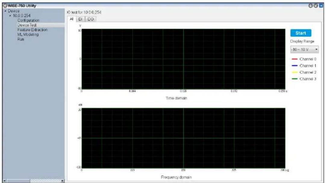
Go to the page Device Test to test your device. In this page, you'll be able to test the analog input, digital input and digital output functions respectively. Note that in the runtime, the digital inputs act as trigger and digital outputs act as alarm. The digital I/O tests here are only to let you test the signal connection and make sure all the connections work as expected. For detailed signal connection, please refer to section 3.3.
Application
WISE-750 could operate 3 modes, Intelligent, Rule-base and Datalogger mode. To start with the modes, you should set the running mode in Configuration page then switch the page to corresponded page for further configuration. For detailed settings in each mode, please refer to section 4.7.
Chapter 3
Hardware Overview and Signal Connections
This chapter provides useful information about how to connect input and output signals to the WISE-750 Module via the I/O connector.
Sections include:
Overview
■ IO Indicators and Pin Definition
Signal Connections
Field Wiring Considerations
3.1 Overview
Maintaining signal connections is one of the most important factors in ensuring that your application system is sending and receiving data correctly. A good signal connection can avoid unnecessary and costly damage to your PC and other hardware devices. This chapter provides useful information about how to connect input and output signals to the WISE-750 module via the I/O connector.
3.2 Hardware Overview
Please refer to Figure 3.1 for the location of all IO connectors and indicators.

Figure 3.1 Connector and Switch Locations
Pin Assignment
Connector Description
| Pin Description Pin Description | |||
| CH0 Analog Input channel 0 CH1 Analog input channel 1 | |||
| CH2 Analog input channel 2 CH3 Analog input channel 3 | |||
| DI0 | Digital input channel 0 | DI1 Digital input channel 1 | |
| DI2 | Digital input channel 2 | DI3 Digital input channel 3 | |
| DO0 | Digital output channel 0 | DO1 | Digital output channel 1 |
| DO2 | Digital output channel 2 | DO3 | Digital output channel 3 |
| EC | Common pin for digital input | PC | Common input for digital output |
| GND Ground USB Reserved, no function | |||
| LAN1 | Ethernet Port 1 | LAN2 | Ethernet Port 2 |
| PWR+ | Positive power connection PWR- | 0V or GND connection for power input | |
■ Analog Input Pin Assignment (4-pin connector)

Figure 3.2 Pin assignment of 4-pin connector
3.2.1 IO Status Indicators
Module Status
PWR - Indicates the power if the module is connected to 10\~30VDC power supply ERR - Indicates if the status is abnormal RUN - Indicates if the program is running
| LED Status | |||
| Off On Blinking | |||
| PWR Power OFF Power ON - | |||
| ERR Normal | - Abnormal Session Stoppage (Need to reboot the module)- IP address conflicting (This would automatically resume when the conflict is resolved) | -- | |
| RUN Program Not Ready Program Ready | -Booting up to main program- Updating firmware | ||
Channel Status
Each of the analog input channel has a corresponded LED indicator. The LED lights up when the channel alarm happens.
| LED Status | ||
| Off On | ||
| CHx Channel | OK Channel | Alarm |
3.3 Signal Connection
3.3.1 Analog Input
The WISE-750 accepts 0\~20mA current input. The sensor PCL-M10 packed along with the WISE-750 follows the specification and can be connected to the WISE-750 directly. If there's another sensor to be connected to WISE-750, it should follow figure 4.
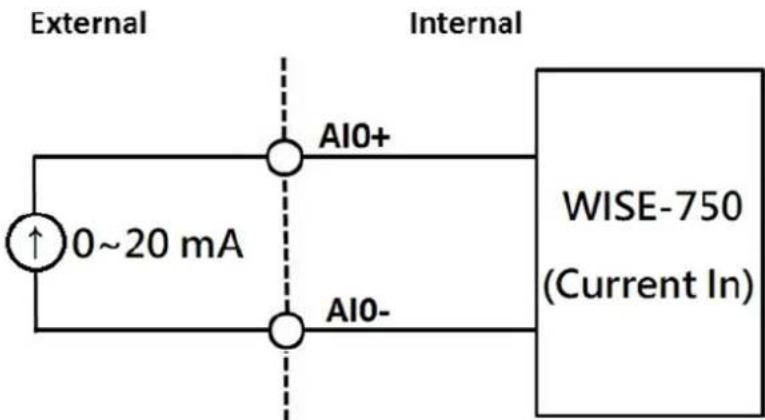
Figure 3.3 Analog Input for current
The WISE-750-02A1E package includes 2 accelerometers PCL-M10-3E by default. The sensor can be connected to the WISE-750 analog channel 0\~3 directly. However, if you'd like to connect your own sensor to the WISE-750, you should connect your sensor to the 4-pin connector with the pin-assignment below.

Figure 3.4 Pin assignment of 4-pin connector
3.3.2 PCL-M10
The PCL-M10 is designed to connect to WISE-750 directly. In some of the models, PCL-M10(s) is packed along with the WISE-750. The PCL-M10 follows the pin assignment of 3.3.1. Connect directly to the analog input channels, then you can test the accelerometer PCL-M10 in Device Test page.

natural_image
Blue WISE-750 network device with USB cable and connector ports, no visible text or symbols on main bodyFigure 3.5 WISE-750 connect to PCL-M10
3.3.3 Isolated Digital Input
Each of the isolated digital input channels accepts bi-directional 10 \~ 30 VDC voltage inputs. This means that both positive and negative voltage can be applied to an isolated input pin (VIN). Figure 2 shows how to connect an external input source to one of the module's isolated input channels.

Figure 3.6 Isolated Digital Input Connection
3.3.4 Isolated Digital Output
The WISE-750 refers the digital output as alarm. When the inspection criteria is reached, the alarm would be pulled to high automatically, in order to trigger the external equipment. The signal connection is shown in figure 3.

Figure 3.7 Isolated Digital Output Connection
3.4 Hardware Installation
WISE-750 can be integrated with a DIN-Rail mount for easy operation.
- Take out the mount kit from the package.
- Install the DIN-rail kit using the 3 screws provided in the pack.
3.5 Field Wiring Considerations
When you use WISE-750 module to acquire data from outside, noises in the environment might significantly affect the accuracy of your measurements if due cautions are not taken. The following measures will be helpful to reduce possible interference running signal wires between signal sources and the WISE-750 module.
The signal cables must be kept away from strong electromagnetic sources such as power lines, large electric motors, circuit breakers or welding machines, since they may cause strong electromagnetic interference. Keep the analog signal cables away from any video monitor, since it can significantly affect a data acquisition system.
If the cable travels through an area with significant electromagnetic interference, you should adopt individually shielded, twisted-pair wires as the analog input cable. This type of cable has its signal wires twisted together and shielded with a metal mesh. The metal mesh should only be connected to one point at the signal source ground.
- Avoid running the signal cables through any conduit that might have power lines in it.
If you have to place your signal cable parallel to a power line that has a high voltage or high current running through it, try to keep a safe distance between them. Alternatively, you can place the signal cable at a right angle to the power line to minimize the undesirable effect.
3.6 Ethernet Connection
The WISE-750 has two LAN port with RJ45 connector. To connected with WISE-750, you should use at least CAT 5e cable with RJ-45 connector to connect to the WISE-750.
The WISE-750 supports daisy chain. The topology could be expanded with this feature. (Figure 3.7)

flowchart
graph TD
    PC["PC"] -->|USB| LAM1["LAM1"]
    LAM1 -->|USB| LAM2["LAM2"]
    LAM2 -->|USB| LAM1
    LAM1 -->|USB| LAM2
    LAM2 -->|USB| LAM1
    LAM1 -->|USB| LAM2
    LAM2 -->|USB| LAM1
    LAM1 -->|USB| LAM2
    LAM2 -->|USB| LAM1
    LAM1 -->|USB| LAM2
    LAM2 -->|USB| LAM1
    LAM1 -->|USB| LAM2
    LAM1 -->|USB| LAM2
    LAM2 -->|USB| LAM1
    LAM2 -->|USB| LAM2
Figure 3.8 Daisy Chain for WISE-750
Chapter 4
Device Configuration
Sections include:
Software Interfaces
IP Configuration
Overview of WISE-750 Operation
Data Acquisition Parameters
Trigger Settings
Operation Modes
4.1 Software Interfaces
To configure the WISE-750, you need to download and install the WISE-750 Utility from Advantech support portal. The installation package will guide you through the installation and install essential components in your system. After the installation, you'll see the WISE-750 Utility. You'll see the interface when you start the utility. The utility will scan all the available WISE-750 devices connected to your computer when it starts.
4.2 Software Interface
There are two parts in WISE-750 utility. One is the device tree view on the left hand side, the other is specific settings. The device will be listed on the device tree view, labeled with its IP address when the system is connected with WISE-750 via Ethernet. The contents under each WISE-750 could be operated after click each functions. The available functions are: Configuration, Device Test, Feature Extraction, ML Modeling and Run.
Configuration
This function provides all the device configuration, including network configuration, run mode and DAQ configuration.

Figure 4.1 Configuration Page
Device Test
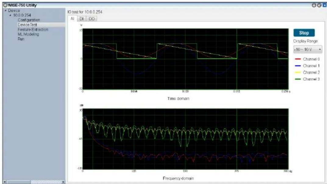
This function allows you to tests all the functions of WISE-750 in terms of signal connection. Each page performs its corresponded functions from analog input, digital input to digital output. Note that the FFT plot in analog test is transformed from time-domain data in the computer. It is not transformed by WISE-750 itself.
line
| Time domain | Channel 0 | Channel 1 | Channel 2 | Channel 3 | | ----------- | --------- | --------- | --------- | --------- | | 0 | ~8 | ~6 | ~7 | ~9 | | 0.054 | ~6 | ~4 | ~5 | ~7 | | 0.139 | ~8 | ~6 | ~7 | ~9 | | 0.192 | ~6 | ~4 | ~5 | ~7 | | 0.256 | ~8 | ~6 | ~7 | ~9 | | Frequency domain | Channel 0 (top) | Channel 1 (bottom) | Channel 2 (top) | Channel 3 (bottom) | | - | - | - | - | - | | - | - | - | - | - | | - | - | - | - | - | | - | - | - | - | - | | - | - | - | - | - | | - | - | - | - | - | | - | - | - | - | - | | - | - | - | - | - | | - | - | - | - | - | | - | - | - | - | - | | - | - | - | - | - | | - | - | - | - | - | | - | - | - | - | - | | - | - = 0 | - | - | - | | - | - = 0 | - | - | - | | - | - = 0 | - | - | - | | - | - = 0 | - | - | - | | - | - = 0 | - | - | - | | - | - = 0.5 | - | - | - | | - | - = 0.5 | - | - | - | | - | - = 0.5 | - | - | - | | - | - = 0.5 | - | - | - | | - | - = 0.5 | - | - | - | | ... | ... | ... | ... | ... | | 0 | 0.5 | 0.3 | 0.4 | 0.2 | | 0.139 | 0.3 | 0.1 | 0.2 | 0.1 | | 0.192 | 0.1 | 0.0 | 0.1 | 0.0 | | 0.256 | 0.0 | 0.0 | 0.0 | 0.0 | | ... | ... | ... | ... | ... | | ... | ... | ... | ... | ... | | ... | ... | ... | ... | ... | | ... | ... | ... | ... | ... | | ... | ... | ... | ... | ... | | ... | ... | ... | ... | ... | | ... | ... | ... | ... | ... | | .. | ... | ... | ... | ... | | .. | ... | ... | ... | ... | | .. | ... | ... | ... | ... | | .. | ... | ... | ... | ... | | .. | ... | ... | ... | ... | | .. | ... | ... | ... | ... | | .. | ... = 1 | ... | ... | ... | | .. | ... = 1 | ... | ... | ... | | .. | ... = 1 | ... | ... | ... | | .. | ... = 1 | ... | ... | ... | | .. | ... = 1 | ... | ... | ... | | .. | ... = 1.5 | ... | ... | ... | | .. | ... = 1.5 | ... | ... | ... | | .. | ... = 1.5 | ... | ... | ... | | .. | ... = 1.5 | ... | ... | ... | | .. | ... = 1.5 | ... | ... | ... | | . , .. , .. , .. , .. , .. , .. , .. , .. , .. , .. , .. , .. , .. , .. , .. , .. , .. , .. , .. , .. , .. , .. , .. , .. , .. , .. , .. , .. , .. , .. , .. , .. , .. , .. , .. , ..Figure 4.2 Device Test Page
Feature Extraction
In this page, the function of feature extraction can be set. To activate this page, the run mode should be set to "Feature Extraction Mode" in Configuration page. The data logging and alarm criteria could be set in this page. For more information, please refer to 4.6.2 Feature Extraction Mode.

Figure 4.3 Feature Extraction Page
ML Modeling
The machine learning related functions are all in this page. To activate this page, the run mode should be set to "Intelligent Mode" in Configuration page. The dataset
retrieving, model training and alarm criteria could be set in this page. For more information, please refer to 4.6.3 Intelligent Mode.

Figure 4.4 Machine Learning Page
Run
All the results can be instantly viewed from this page.
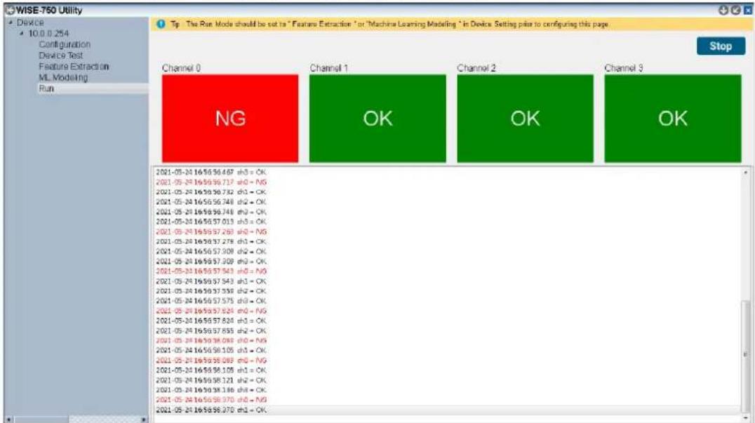
Figure 4.5 Run Page
Multiple Module Connection
The software supports multiple connection in the system, no matter if it's connected by daisy chain, through switch etc. The devices would be listed in the system when they are set to different IPs and connected. (Figure 4.6)
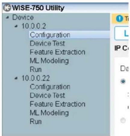
Figure 4.6 Multiple WISE-750 being listed in device tree view
4.3 IP Configuration
The IP Configuration is the first thing to do when you start configuring the WISE-750. The device itself has a default IP setting of 10.0.0.1. In order to successfully connect to WISE-750 in the beginning of using the device, you need to configure your NIC IP connected to WISE-750 to the same section (10.0.0.x with sub-net mask 255.255.255.0). After that, you can revise the IP in IP Config. Press the button to set the IP and then the WISE-750 will reboot automatically to apply the setting.
Note! It's suggested to shut down the Windows firewall and the anti-virus software while connecting to WISE-750. The WISE-750 relies on UDP communication, which is likely to be blocked by firewall and antivirus.
4.4 Overview of WISE-750 Operation
The WISE-750 follows Figure 4.7 in its operation. An iteration cycle includes data acquisition, calculation and communication. The data acquisition starts right after the end of previous cycle to retrieve analog data (vibration data) into the system. After acquisition, WISE-750 will execute the corresponded calculation and judgment based on the judgment type. Then, the result will be sent out through Ethernet and digital output. Another cycle will start right after the end of the communication session from data acquisition.
![[Section Length] samples Acquisition Clock ... ... ... DAQ CAL COM 1 Cycle](/content/2026/06/1250113/images/b2b13bab55385cc11d1aaf558a356325940e2e052262a4c5ef29f6e978ea3a02.jpg)
Figure 4.7 Process of the WISE-750 application
4.5 Data Acquisition Parameters
There are several parameters to set in order to catch vibration signals without any aliasing or resource wasting.
Sampling Rate
The speed to acquire the vibration, the unit is S/s which stands for samples per second.
Section Length
Number of samples to be retrieved in each iteration cycle.
Cycle Count
Number of iteration cycles to be made in each trigger. Figure 4.8 describes the reaction when section count is set to a non-zero value.

flowchart
graph TD
    A["DAQ"] --> B["..."]
    C["CAL"] --> D["..."]
    E["COM"] --> F["..."]
    G["..."] --> H["..."]
    I["..."] --> J["..."]
    K["..."] --> L["..."]
    M["..."] --> N["..."]
    O["..."] --> P["..."]
    Q["..."] --> R["..."]
    S["..."] --> T["..."]
    U["..."] --> V["..."]
    W["..."] --> X["..."]
    Y["..."] --> Z["..."]
    AA["..."] --> AB["..."]
    AC["..."] --> AD["..."]
    AE["..."] --> AF["..."]
    AG["..."] --> AH["..."]
    AI["..."] --> AJ["..."]
    AK["..."] --> AL["..."]
    AM["..."] --> AN["..."]
    AO["..."] --> AP["..."]
    AQ["..."] --> AR["..."]
    AS["..."] --> AT["..."]
    AU["..."] --> AV["..."]
    AW["..."] --> AX["..."]
    AY["DAQ"] --> Z
    AZ["CAL"] --> AA
    BA["COM"] --> BB
    BC["..."] --> BC
    BD["..."] --> BD
    BE["..."] --> BF
    BG["CAL"] --> BH
    BI["COM"] --> BJ
    BK["..."] --> BK
    BL["CAL"] --> BM
    BN["COM"] --> BO
    BP["CAL"] --> BP
    BQ["CAL"] --> BQ
    BN["CAL"] --> BN
    BO["CAL"] --> BO
    BP["CAL"] --> BP
    BQ["CAL"] --> BQ
    style A fill:#d4edda,stroke:#333
    style B fill:#d4edda,stroke:#333
    style AC fill:#d4edda,stroke:#333
    style AD fill:#d4edda,stroke:#333
    style AE fill:#d4edda,stroke:#333
    style AF fill:#d4edda,stroke:#333
    style AG fill:#d4edda,stroke:#333
    style AH fill:#d4edda,stroke:#333
    style AI fill:#d4edda,stroke:#333
    style AJ fill:#d4edda,stroke:#333
    style AK fill:#d4edda,stroke:#333
    style AL fill:#d4edda,stroke:#333
    style AM fill:#d4edda,stroke:#333
    style AN fill:#d4edda,stroke:#333
    style AO fill:#d4edda,stroke:#333
    style AP fill:#d4edda,stroke:#333
    style AQ fill:#d4edda,stroke:#333
    style AR fill:#d4edda,stroke:#333
Figure 4.8 Trigger and Cycle Count
If the section count is set to 0, this would act as continuous mode. Each cycle would be started right after previous cycle until stop trigger happens. In this mode, the trigger would act as a gate to control the iteration. See Figure 4.9.

flowchart
graph TD
    A["DAQ"] --> B["..."]
    C["CAL"] --> D["..."]
    E["COM"] --> F["..."]
    G["Digital Trigger"] --> H["Signal Waveform"]
    style A fill:#d4edda,stroke:#333
    style C fill:#d4edda,stroke:#333
    style E fill:#d4edda,stroke:#333
    style G fill:#d4edda,stroke:#333
    style B fill:#fff,stroke:#333
    style D fill:#fff,stroke:#333
    style F fill:#fff,stroke:#333
    style H fill:#fff,stroke:#333
Figure 4.9 Trigger and Cycle Count
4.6 Trigger Settings
4.6.1 Trigger Source
Select the trigger source via the options in the combo box. Options are: None, Digital Input, and Analog Input from the respective channels to be chosen from. Whenever the trigger is set to None, WISE-750 will run right after the setting is downloaded to the machine. Otherwise, the cycles would start when receiving the trigger signal/action.
4.6.2 Trigger Types
Digital Trigger
The digital trigger of WISE-750 uses the level trigger. There are two options "Active High" and "Active Low" to trigger the iteration cycle. That means, a trigger is generated whenever the level of trigger source is HIGH (Active High) or LOW (Active Low) based on the settings. On the other hand, in the context of analog trigger, the options would be changed to beyond (>) or under (<) trigger level. In the meantime, the filter can also be set (see the section Filter).
Figure 4.10 describes the action in the context where the type is set to Digital Trigger and Active High. In the beginning of the cycle, the trigger signal is high. In this situation, a trigger would be generated. The triggers are also effective when the signal turns to high, just like the consecutive two pulses. Whenever the process idles and meets the active zone, the process cycle will be triggered. This mechanism could also be applied when setting type to Active Low.

line
| State | Trigger Level | | --------- | ------------- | | Active | High | | Inactive | Low | | Active | High | | Active | Low | | Inactive | Low | | Active | High | | Inactive | Low |Figure 4.10 Digital Trigger
Analog Trigger
When the trigger type is set to ">" (greater than) level, a trigger will be generated when the incoming signal condition is fulfilled.
See Figure 4.11.

line
| Time Segment | Voltage (V) | | ------------ | ----------- | | 1 Cycle | Low | | Peak | High | | 1 Cycle | Low | | Peak | High |Figure 4.11 Analog Trigger
Triggers won't be generated when the cycle is already running. The trigger signal would be referred to as ineffective when the process is already running. See Figure 4.12.

line
| Step | Value | |------|-------| | 1 | Low | | Acquisition Starts | Peak | | Ineffective Trigger, no action taken | Low |Figure 4.12 Analog Trigger and Cycle
4.6.3 Trigger Level
This would only be available when using analog triggers. This is the trigger voltage level. The trigger would be generated when the voltage passes through this value. This field would only be available when the trigger source is analog input.
Filter
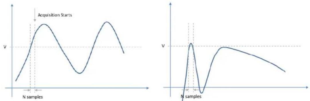
Figure 4.13 Left: Trigger Acquisition. Right: No Further Action
Refer to Figure 4.13. The filter parameter sets a sample count. The sample count is a period to measure if all of the values within these period of time exceed the trigger level. If they are, this would allow trigger generation. If they aren't, no trigger would be generated.
4.7 Operation Modes
There are three modes that could be run in the WISE-750. They are Datalogger, Feature Extraction, and Intelligent Mode respectively. You can set them in the WISE-750 Utility. They are independent modes. They each have their own functions respectively. The function of each mode cannot be used in other modes. For example, the Datalogger function in Datalogging mode cannot be used in Extraction Mode and Intelligent Mode.
4.7.1 Datalogger Mode
The Datalogger Mode is hte default mode when first starting the application. No matter the final application is in Feature Extraction Mode or Intelligent Mode, this function is always used in the starting stage of the application. After data logging, users can analyze the data then understand the data features and will be able to set the criteria afterwards. To use the datalogger, switch the utility to "Feature Extraction" Page.
Options and Parameters:
Data Type: Choose Feature Values or Raw Data to set the data type you'd like to saves the data for.
File Count: The datalogger will save corresponded number of files according to this parameter. For non-zero file count setting, the logger will save corresponded number of files to the directory you set. For file count 0, the logger will save the files until you press the stop button. The settings in different mode will result in different types of data logging:
- Raw Data Mode: the datalogger will save data to file with the number of section length data written in the file and save number of files for this parameter. For example, if you set the section length for 2048 and file count for 100, there will be 100 files saved and 2048 rows of data in each file.
- Feature Extraction Mode: the datalogger will save feature data (calculated in every iteration of section length) to file with 100 rows of feature data in each file. The file count sets the number of files to be saved.
Destination: set the data logger directory in this PC.
Configuration Process:
-
Select the data logging types. The option "Feature Values" will save the feature values to the destination you set.
-
Enter the file count in the box.
- Click "..." button to enter a destination of your data.
- Click on the Start button then the data logging will be started.
4.7.2 Feature Extraction Mode
The Feature Extraction Mode allows you to set the alarm using the feature values we provided already in WISE-750. They are maximum, minimum, peak value, peak to peak and RMS respectively. To employ this mode, the alarm type of WISE-750 needs to be set to "Feature Extraction" in Configuration Page.
Alarm Threshold Setting
You can choose which feature value you are concerned about by checking the box and then entering the criteria. Finally, press the button "Save To Device" to set the alarm criteria to WISE-750. After that, the condition monitoring using criteria setting will be started.
For the details of all the feature values, please refer to Appendix B.
4.7.3 Intelligent Mode
Machine Learning Model Building
The Intelligent Mode operates the condition monitoring by machine learning algorithm. The WISE-750 allows you to set models for each channel. The training data set is pre-processed by FFT to transfer from time domain to frequency domain. Follow the steps below to employ Intelligent Mode in WISE-750:
- Set the alarm type to Machine Learning and the channels in Configuration page.
- Switch to ML Modeling page
- Set the number of data set you'd like to train the model with. Every data set is saved to a file. Each file contains data count of half of the section length. For example, if you set the file count to 100 and section length to 2048, there will be 100 files and each file containing 1024 data comes after FFT (Fast Fourier Transform).
- Set the destination. This would be the path of the data set. We strongly suggest you to fix this path once you decide to use this mode.
- Press start then the datalogger will start to retrieve the data set for machine learning. The datalogger will follow the parameter you set in Configuration to get the data. If you set the trigger, the datalogger will get data until the trigger happens.
- After retrieving the data set, the dataset will be listed in the column Dataset Selection. Select the dataset you'd like to train the model with.
- Press start. This will train the model and also download the model to each selected channel.
Alarm Threshold Setting
The training session will build and download the model to the WISE-750. In the inference session, the WISE-750 will indicate if the iteration is OK or NG. The WISE-750 will give a score to indicate the status of the measured machine/component. The score is calculated using success rate in the past N iterations, while N is user-configurable in Alarm Setting page. For example, if the number is set to 200 and there are 160 Oks in the past 200 iterations, the score will be 160/200 × 100 = 80 . Users need to set an alarm threshold for the score. Hence, the WISE-750 will generate the alarm when the score is lower than the threshold. Then, press the button to set the parameters for the device.
4.8 Device Communication
WISE-750 supports instant data reading and input from protocols. To retrieve instant values from WISE-750, please make sure the WISE-750 is running and then follow the mapping table to get corresponded values.
4.8.1 Modbus
WISE-750 provides Modbus mapping for instant feature values and inspection results. For detailed mapping table, please refer to Appendix C.
4.9 Alarm Generation
Alarm thresholds could be set in WISE-750. The setting interface is in the "Feature Extraction" and "ML Modeling" page respectively. The inspection result could either be retrieved from communication interfaces or corresponded digital output. For example, if WISE-750 finds that channel 0 fail to pass the threshold, the digital output 0 will be set to High level. Otherwise, in the normal situation, the digital output will stay in Low level. For the communication protocol table and digital output specification, please refer to Appendix A and Appendix C.
4.10 System Requirements
The installation package installs essential components altogether, including Python and Tensorflow. The system should be a 64-bit Windows system, at least Windows 7 and suggested to be Windows 10.
Appendix
A
Specifications
A.1 Analog Input
A.1.1 Functions
■ Channels: 4 single-ended, simultaneous sampling
■ Input coupling: DC
■ Input range: ±10 V, 0 \~ 20 mA
■ A/D converter (ADC) resolution: 16 bits
■ A/D converter (ADC) type: successive approximation (SAR)
■ Maximum sample rate (fs): 200 KS/s
■ Sample clock source: internal
■ Maximum working voltage for all analog inputs: ±15 V
■ Integral non-linearity error (INLE): ± 2 LSB
■ Differential non-linearity error (DNLE): ± 1 LSB
■ Voltage Input impedance: 1 MΩ in parallel with 5 pF
■ Current Input impedance: 500 Ω
■ Built-in memory: 4096 samples
A.1.2 Voltage Measurement Accuracy
Gain error
Operating temperature within 5 °C of last auto-calibration temperature: < ±0.02%
Over full operating temperature range: < ±0.08%
Offset error
Operating temperature within 5 °C of last auto-calibration temperature: < ±0.7 mV
Over full operating temperature range: < ±9 mV
A.1.3 Current Measurement Accuracy
Gain error
Operating temperature within 5 °C of last auto-calibration temperature: < ±0.03%
Over full operating temperature range: < ±0.09%
Offset error
Operating temperature within 5 °C of last auto-calibration temperature: < ± 10 μA
Over full operating temperature range: < ± 45 μA
A.1.4 Dynamic Performance
-3 dB bandwidth: 23 KHz
■ Idle channel noise: 0.61 mVrms
■ Effective number of bits (ENOB): 13.5 Bits @(fin = 1KHz)
■ Signal-to-Noise Ration (SNR): 85 dB @(fin = 1KHz)
■ Total Harmonic Distortion (THD): -91 dB @(fin = 1KHz)
■ Total Harmonic Distortion pulse Noise (THD+N): -84 dB @(fin = 1KHz)
A.2 Triggers
- Trigger function: start trigger, stop trigger (refer to IDI)
A.3 Isolated Digital Input
Channels: 4
■ Logic "0" level: 0 - 3 VDC
■ Logic "1" level: 10 – 30 VDC
■ Input Resistance: 3.2 KΩ
■ Wiring Type: dry contact, wet contact
■ Isolation Protection: 2,500 VDC
■ Opto-Isolator Response: 100 us
A.4 Isolated Digital Output
Channels: 4
■ Output Type: sink (NPN)
■ Sink Current: 500 mA max./channel
■ Isolation Protection: 2,500 VDC
■ Opto-Isolator Response: 100 us
A.5 General
■ Power input: 10\~30V DC
■ Power Consumption:
+24 V: 70 mA typ. / 250mA max. (without sensors connected)
■ Dimensions: 133 × 40 × 98 mm
I/O connector: 4 x 4-pin connectors and 1 x 12-pin connector
■ Operating temperature: 0 to 60 °C (32 to 140 °F)
■ Storage temperature: -40 to 70 °C (-40 to 158 °F)
■ Operating humidity: 10 to 90% RH, non-condensing
■ Storage humidity: 5 to 95% RH, non-condensing
Appendix
B
Algorithms
■ AVG (Average) - Average of the numbers, a calculated "central" value of a set of numbers.
■ MAX (Maximum) - The maximum value of Y-axis on the plot.
■ MIN (Minimum) - The minimum value of Y-axis on the plot.
- Peak To Peak - The difference between the maximal positive value and the minimal negative value of a waveform.
- Peak - The maximum of the absolute of the waveform
$$ \text { Peak } = \operatorname{Max} (| F (n) |) $$
RMS - The root mean square (abbreviated RMS or rms) is defined as the square root of the mean square (the arithmetic mean of the squares of a set of numbers).
$$ \mathrm{RMS} = \sqrt {\sum F (n) ^ {2}} $$
Measurement of PCL-M10 - The formula to transform the voltage to vibration value is (voltage)/(sensitivity). PCL-M10 itself will have a DC voltage of 5V in default.
So, the formula to transfer PCL-M10 voltage to vibration is
Acceleration = (Voltage - 5 / 0.08) g
For example, a 6V in measurement could be transferred to (6-5)/0.08 = 12.5g.
Appendix C
I/O Ranges
C.1 Modbus Mapping
| Table C.1: Modbus Mapping | ||||||||
| Available Mode | Tag Name Type | Modbus Address | Remark | |||||
| Ch0 Ch1 Ch2 Ch3 Global | ||||||||
| Feature Extraction | Rule-base Result | INT 30 | 001 301 | 01 302 | 01 303 | 01 | 0: Pass, 1: Fail | |
| MAX | INT 30 | 003 30 | 103 30 | 203 30 | 303 | 2 digit decimal* | ||
| MIN | INT 30 | 005 30 | 105 30 | 205 30 | 305 | 2 digit decimal* | ||
| MEAN | INT 30 | 007 30 | 107 30 | 207 30 | 307 | 2 digit decimal* | ||
| Peak | INT 30 | 009 30 | 109 30 | 209 30 | 309 | 2 digit decimal* | ||
| Peak To Peak | INT | 30011 | 30111 | 30211 | 30311 | 2 digit decimal* | ||
| RMS | INT 30 | 013 30 | 113 30 | 213 30 | 313 | 2 digit decimal* | ||
| Intelligent | Inference Result | INT 30 | 015 30 | 115 30 | 215 30 | 315 | 0: Pass, 1: Fail | |
| Score | INT 30 | 017 30 | 117 30 | 217 30 | 317 | 2 digit decimal* | ||
| Score Threshold | INT | 30019 | 30119 | 30219 | 30319 | 2 digit decimal* | ||
| All | Running Mode | INT | 30401 | 0: Datalogger, 1: Feature, 2: Intelligent | ||||
| Running Status INT | 30 | 403 | 0: Idle, 1: Running | |||||
| Cycle Start/Stop | INT | 40401 | 0: Stop, 1: Start | |||||
*The value includes 2-digit decimal. To retrieve the actual value, a division of 100 should be performed. For example, if the value read back is 1000, the actual value would be 1000 / 100 = 10 .
www.advantech.com
Please verify specifications before quoting. This guide is intended for reference purposes only.
All product specifications are subject to change without notice.
No part of this publication may be reproduced in any form or by any means, such as electronically, by photocopying, recording, or otherwise, without prior written permission from the publisher.
All brand and product names are trademarks or registered trademarks of their respective companies.
© Advantech Co., Ltd. 2021

- WISE-750
- Intelligent Vibration Sensing Gateway
- Copyright
- Acknowledgments
- Product Warranty (2 years)
- Declaration of Conformity
- CE
- Technical Support and Assistance
- Packing List
- Safety Precaution - Static Electricity
- Contents
- Chapter 1 Introduction......1
- Chapter 2 Installation....5
- Chapter 3 Hardware Overview and Signal Connections9
- Chapter 4 Device Configuration .....17
- Appendix A Specifications.... 29
- Appendix B Algorithms 33
- Appendix C I/O Ranges 35
- Features
- Applications
- Installation Guide
- Accessories
- Sensor
- Chapter 2
- Unpacking
- Configuration with WISE-750 Utility
- Device Connection
- Note!
- Device Test
- Application
- Chapter 3
- Hardware Overview and Signal Connections
- Overview
- Hardware Overview
- IO Status Indicators
- Module Status
- Channel Status
- Signal Connection
- Analog Input
- PCL-M10
- Isolated Digital Input
- Isolated Digital Output
- Hardware Installation
- Field Wiring Considerations
- Ethernet Connection
- Chapter 4
- Device Configuration
- Sections include:
- Software Interfaces
- Software Interface
- Configuration
- Feature Extraction
- ML Modeling
- Run
- Multiple Module Connection
- IP Configuration
- Overview of WISE-750 Operation
- Data Acquisition Parameters
- Sampling Rate
- Section Length
- Cycle Count
- Trigger Settings
- Trigger Source
- Trigger Types
- Digital Trigger
- Analog Trigger
- Trigger Level
- Operation Modes
- Datalogger Mode
- Options and Parameters:
- Configuration Process:
- Feature Extraction Mode
- Alarm Threshold Setting
- Intelligent Mode
- Machine Learning Model Building
- Device Communication
- Modbus
- Alarm Generation
- System Requirements
- Appendix
- A
- A.1 Analog Input
- A.1.1 Functions
- A.1.2 Voltage Measurement Accuracy
- A.1.3 Current Measurement Accuracy
- A.1.4 Dynamic Performance
- A.2 Triggers
- A.3 Isolated Digital Input
- A.4 Isolated Digital Output
- A.5 General
- B
- Algorithms
- Appendix C
- C.1 Modbus Mapping
- www.advantech.com
Brand : Advantech
Model : WISE-750-02A1E
Category : Unspecified