
WISE-4210-APNA - Unspecified Advantech - Free user manual and instructions
Find the device manual for free WISE-4210-APNA Advantech in PDF.

| Product Type | LPWAN IoT Wireless to Ethernet Access Point |
| Model | WISE-4210-APNA |
| Dimensions (W x H x D) | 70 x 112 x 38 mm |
| Weight | Approximately 200 g |
| Power Input | 10-50 V DC, 0.8 W @ 24 V DC |
| Operating Temperature | -20 to 70°C (-4 to 140°F) |
| Storage Temperature | -40 to 85°C (-40 to 185°F) |
| Humidity | 5-95% RH (non-condensing) |
| Wireless Standard | IEEE 802.15.4g |
| Frequency Bands | 868 MHz (EU), 915 MHz (NA), 923 MHz (NA), 433 MHz (UN) |
| Data Rate | 625 bps / 2.5 Kbps / 5 Kbps / 50 Kbps |
| Outdoor Range (625 bps) | 5 km (line of sight) |
| Maximum End Nodes | 64 |
| Configuration Interface | RJ-45 Ethernet port (web browser) |
| Protocols | Modbus/TCP, RESTful Web API, TCP/IP, UDP, HTTP, HTTPS, DHCP, ARP, SNTP |
| LED Indicators | Status, Error, Rx, Tx, LAN (Link and Speed) |
| Mounting Options | DIN rail, wall, pole |
| Enclosure Material | PC (polycarbonate) |
| Certifications | CE (RED), FCC Class A, IC, NCC |
| Included Accessories | Mounting bracket, China RoHS (UA series only), Antenna (UA series only) |
| Optional Accessories | Antenna (1750008836-01/8837-01), Battery (1760002647-01), USB cable (1700023619-01) |
| Maintenance | Disconnect power before cleaning; use a damp cloth, no liquids or sprays |
| Safety | FCC Class A: may cause interference in residential areas; IC: radiation exposure distance 20 cm |
Frequently Asked Questions - WISE-4210-APNA Advantech
User questions about WISE-4210-APNA Advantech
0 question about this device. Answer the ones you know or ask your own.
Ask a new question about this device
Download the instructions for your Unspecified in PDF format for free! Find your manual WISE-4210-APNA - Advantech and take your electronic device back in hand. On this page are published all the documents necessary for the use of your device. WISE-4210-APNA by Advantech.
USER MANUAL WISE-4210-APNA Advantech
The documentation and the software included with this product are copyrighted 2020 by Advantech Co., Ltd. All rights are reserved. Advantech Co., Ltd. reserves the right to make improvements in the products described in this manual at any time without notice. No part of this manual may be reproduced, copied, translated or transmitted in any form or by any means without the prior written permission of Advantech Co., Ltd. Information provided in this manual is intended to be accurate and reliable. However, Advantech Co., Ltd. assumes no responsibility for its use, nor for any infringements of the rights of third parties, which may result from its use.
Acknowledgements
Intel and Pentium are trademarks of Intel Corporation.
Microsoft Windows and MS-DOS are registered trademarks of Microsoft Corp.
All other product names or trademarks are properties of their respective owners.
Product Warranty (2 years)
Advantech warrants to you, the original purchaser, that each of its products will be free from defects in materials and workmanship for two years from the date of purchase.
This warranty does not apply to any products which have been repaired or altered by persons other than repair personnel authorized by Advantech, or which have been subject to misuse, abuse, accident or improper installation. Advantech assumes no liability under the terms of this warranty as a consequence of such events.
Because of Advantech's high quality-control standards and rigorous testing, most of our customers never need to use our repair service. If an Advantech product is defective, it will be repaired or replaced at no charge during the warranty period. For out-of-warranty repairs, you will be billed according to the cost of replacement materials, service time and freight. Please consult your dealer for more details.
If you think you have a defective product, follow these steps:
-
Collect all the information about the problem encountered. (For example, CPU speed, Advantech products used, other hardware and software used, etc.) Note anything abnormal and list any onscreen messages you get when the problem occurs.
-
Call your dealer and describe the problem. Please have your manual, product, and any helpful information readily available.
-
If your product is diagnosed as defective, obtain an RMA (return merchandise authorization) number from your dealer. This allows us to process your return more quickly.
-
Carefully pack the defective product, a fully-completed Repair and Replacement Order Card and a photocopy proof of purchase date (such as your sales receipt) in a shippable container. A product returned without proof of the purchase date is not eligible for warranty service.
-
Write the RMA number visibly on the outside of the package and ship it prepaid to your dealer.
Part No. 2003421021 Edition 2
Printed in Taiwan March 2020
Declaration of Conformity
FCC Class A
Note: This equipment has been tested and found to comply with the limits for a Class A digital device, pursuant to part 15 of the FCC Rules. These limits are designed to provide reasonable protection against harmful interference when the equipment is operated in a commercial environment. This equipment generates, uses, and can radiate radio frequency energy and, if not installed and used in accordance with the instruction manual, may cause harmful interference to radio communications. Operation of this equipment in a residential area is likely to cause harmful interference in which case the user will be required to correct the interference at his own expense.
This transmitter must not be co-located or operating in conjunction with any other antenna or transmitter.
Technical Support and Assistance
- Visit the Advantech web site at www.advantech.com/support where you can find the latest information about the product.
- Contact your distributor, sales representative, or Advantech's customer service center for technical support if you need additional assistance. Please have the following information ready before you call:
– Product name and serial number
– Description of your peripheral attachments
– Description of your software (operating system, version, application software, etc.)
– A complete description of the problem
– The exact wording of any error messages
Warnings, Cautions and Notes
Warning! Warnings indicate conditions, which if not observed, can cause personal
injury!

Caution!
Cautions are included to help you avoid damaging hardware or losing data. e.g. There is a danger of a new battery exploding if it is incorrectly installed. Do not attempt to recharge, force open, or heat the battery. Replace the battery only with the same or equivalent type recommended by the manufacturer. Discard used batteries according to the manufacturer's instructions.

Note! Notes provide optional additional information.

Document Feedback
To assist us in making improvements to this manual, we would welcome comments and constructive criticism. Please send all such - in writing to: support@advantech.com
Package List
Before setting up the system, check that the items listed below are included and in good condition. If any item does not accord with the table, please contact your dealer immediately.
WISE-4210-APNA/UA
■ 1 x WISE-4210-APNA/UA LPWAN IoT Wireless to Ethernet AP
■ 1 x Mounting bracket
■ 1x China RoHS (UA series only)
■ 1x Antenna (UA series only)
WISE-4210-S231NA/UA
1 x WISE-4210-S231NA/UA LPWAN IoT Wireless module with temperature and humidity sensor
1 x Mounting bracket
■ 1x China RoHS (UA series only)
■ 1x Antenna (UA series only)
WISE-4210 NA/UA
■ 1 x WISE-4210 NA/UA module
■ 1 x Mounting bracket
■ 1x China RoHS (UA series only)
■ 1x Antenna (UA series only)
WISE-S214-A
1x WISE-S214-A I/O Module
1x China RoHS
4x Screws
1x I/O sticker
WISE-S250-A
1x WISE-S250-A I/O Module
1x China RoHS
4x Screws
1x I/O sticker
WISE-S251-A
1x WISE-S251-A I/O Module
1x China RoHS
4x Screws
1x I/O sticker
Note!Antenna for NA series should be ordered respectively based on the required frequency range.

1750008836-01 863-870MHz Dipole Antenna for WISE-4210
1750008837-01 902-928MHz Dipole Antenna for WISE-4210
Note!Battery needs to be ordered separately

1760002647-01 3.6V/2500mAh AA Cylindrical Battery (non rechargeable)
Safety Instructions
- Read these safety instructions carefully.
- Keep this User Manual for later reference.
- Disconnect this equipment from any AC outlet before cleaning. Use a damp cloth. Do not use liquid or spray detergents for cleaning.
- For plug-in equipment, the power outlet socket must be located near the equipment and must be easily accessible.
- Keep this equipment away from humidity.
- Put this equipment on a reliable surface during installation. Dropping it or letting it fall may cause damage.
- The openings on the enclosure are for air convection. Protect the equipment from overheating. DO NOT COVER THE OPENINGS.
- Make sure the voltage of the power source is correct before connecting the equipment to the power outlet.
-
Position the power cord so that people cannot step on it. Do not place anything over the power cord.
-
All cautions and warnings on the equipment should be noted.
-
If the equipment is not used for a long time, disconnect it from the power source to avoid damage by transient overvoltage.
-
Never pour any liquid into an opening. This may cause fire or electrical shock.
-
Never open the equipment. For safety reasons, the equipment should be opened only by qualified service personnel.
-
If one of the following situations arises, get the equipment checked by service personnel:
-
The power cord or plug is damaged.
-
Liquid has penetrated into the equipment.
-
The equipment has been exposed to moisture.
-
The equipment does not work well, or you cannot get it to work according to the user's manual.
-
The equipment has been dropped and damaged.
-
The equipment has obvious signs of breakage.
-
DO NOT LEAVE THIS EQUIPMENT IN AN ENVIRONMENT WHERE THE STORAGE TEMPERATURE MAY GO BELOW -20°C (-4°F) OR ABOVE 60°C (140°F). THIS COULD DAMAGE THE EQUIPMENT. THE EQUIPMENT SHOULD BE IN A CONTROLLED ENVIRONMENT.
-
CAUTION: DANGER OF EXPLOSION IF BATTERY IS INCORRECTLY REPLACED. REPLACE ONLY WITH THE SAME OR EQUIVALENT TYPE
RECOMMENDED BY THE MANUFACTURER, DISCARD USED BATTERIES ACCORDING TO THE MANUFACTURER'S INSTRUCTIONS.
- The sound pressure level at the operator's position according to IEC 704-1:1982 is no more than 70 dB (A).
DISCLAIMER: This set of instructions is given according to IEC 704-1. Advantech disclaims all responsibility for the accuracy of any statements contained herein.
Safety Precaution - Static Electricity
Follow these simple precautions to protect yourself from harm and the products from damage.
- Disconnect power before making any configuration changes. The sudden rush of power as you connect a jumper or install a card may damage sensitive electronic components.
NCC 警语
Industry Canada statement:
This device complies with ISED's licence-exempt RSSs. Operation is subject to the following two conditions: (1) This device may not cause harmful interference, and (2) this device must accept any interference received, including interference that may cause undesired operation.
Radiation Exposure Statement:
This equipment complies with ISED radiation exposure limits set forth for an uncontrolled environment. This equipment should be installed and operated with minimum distance 20cm between the radiator & your body.
This radio transmitter (IC: 9404A-WISE4210 / Model: WISE-4210-S231, WISE-4210-S251, WISE-4210-AP, WISE-4210) has been approved by ISED to operate with the antenna type listed below with maximum permissible gain indicated. Antenna types not included in this list, having a gain greater than the maximum gain indicated for that type, are strictly prohibited for use with this device.
Approved antenna(s) list
| Type Gain | Brand Manufacturer | ||
| Dipole | 2.19 dBi | Advantech | 1750008836-01 |
| Dipole | 1.33 dBi | Advantech | 1750008837-01 |
Contents
Chapter 1 Product Overview....1
1.1 Series Family and Specifications 2
1.2 Mechanical Design and Dimensions....2 Figure 1.1 WISE-4210 Dimension Front & Side....2
1.3 System Diagram....3 Figure 1.2 WISE-4210 System Diagram....3
1.4 LED Definition 4
1.4.1 WISE-4210-AP....4 Figure 1.3 WISE-4210-AP LED Indicator....4 Figure 1.4 WISE-4210-AP LAN Port LED....5
1.4.2 WISE-4210-S231....5 Figure 1.5 WISE-4210-S231 LED Indicator....5
1.4.3 WISE-4210....7 Figure 1.6 WISE-4210 LED Indicator ....7
1.5 Membrane Button....9 Figure 1.7 WISE-4210 Membrane Button....9
1.6 Battery Power Switch....11 Figure 1.8 WISE-4210 Battery Switch....11
1.7 Package Information 11
Chapter 2 General Specification......13
2.1 General Specification.... 14
2.1.1 Wireless Interface 14
2.1.2 General 15
2.1.3 Power 15
2.1.4 Software....16
2.1.5 Configuration Interface.... 16
2.2 WISE-4210-AP 16
2.2.1 Uplink Communication Port 16
2.2.2 Pin Assignment....17 Figure 2.1 WISE-4210-AP Pin Assignment....17
2.2.3 Block Diagram....17 Figure 2.2 WISE-4210-AP Block Diagram....17
2.3 WISE-4210-S231 17
2.3.1 I/O Specifications 17
2.3.2 Pin Assignment....18 Figure 2.3 WISE-4210-S231 Pin Assignment....18
2.4 WISE-S214 (4AI/4DI) 18
2.4.1 I/O Specifications 18
2.4.2 Pin Assignment....19 Figure 2.4 WISE-S214 Pin Assignment....19
2.5 WISE-S250 (6DI, 2DO& 1RS-485) 19
2.5.1 I/O Specifications 19
2.5.2 Pin Assignment.... 20 Figure 2.5 WISE-S250 Pin Assignment.... 20
2.6 WISE-S251 (6DI/1RS-485) 20
2.6.1 I/O Specifications 20
2.6.2 Pin Assignment.... 20 Figure 2.6 WISE-S251 Pin Assignment.... 20
2.6.3 Application Wiring .... 21 Figure 2.7 WISE-S214 Digital Input Wiring Diagram .... 21 Figure 2.8 WISE-S214 Analog Input Wiring Diagram .... 21 Figure 2.9 WISE-S250 Digital Input Wiring Diagram .... 22
Figure 2.10WISE-S250 Digital Output Wiring Diagram ...... 2 2
Figure 2.11WISE-S250 RS-485 Wiring Diagram.... 23
Figure 2.12WISE-S251 Digital Input Wiring Diagram.... 24
Figure 2.13WISE-S251 RS-485 Wiring Diagram.... 24
2.7 WISE-4210 Node Block Diagram.... 25
Figure 2.14WISE-4210 Node Block Diagram 25
Chapter 3 Hardware Installations.... 27
3.1 Modular Design....28
Figure 3.1 I/O Module Installation.... 28
3.2 Interface Introduction 29
Figure 3.2 WISE-4210 Interface Introduction ...... 29
3.3 Mounting 30
Figure 3.3 WISE-4000 Series Mounting Kit Dimensions ..... 30
3.3.1 DIN-Rail Mounting 30
Figure 3.4 DIN-rail Mounting Installation 30
Figure 3.5 DIN-rail Mounting (front).... 31
Figure 3.6 DIN-rail Mounting (back) 31
3.3.2 Wall Mounting 32
Figure 3.7 Wall Mounting Installation 32
Figure 3.8 Wall Mounting Installation 33
3.3.3 Pole Mounting.... 34
Figure 3.9 Pole Mounting (front).... 34
Figure 3.10 Pole Mounting (back) 35
3.4 Wiring and Connections.... 35
3.4.1 Power Supply Wiring 35
Figure 3.11WISE-4210-AP Power Wiring.... 35
Figure 3.12WISE-4210-S231 Power Wiring 36
Figure 3.13WISE-S200 Power Wiring 36
3.4.2 Battery Installation 36
Figure 3.14WISE-4210 Battery Socket.... 36
Figure 3.15WISE-4210 Battery Switch 37
3.4.3 I/O Units 37
Chapter 4 System Configuration.... 39
4.1 Connection.... 40
4.1.1 WISE-4210-AP Connection 40
Figure 4.1 WISE-4210-AP LAN port.... 40
4.1.2 WISE-4210-Sxxx Node Connection.... 40
Figure 4.2 USB configuration port of WISE-4210 node...... 40
4.2 Configuring WISE-4210-AP with Browser.... 41
4.2.1 System Requirements 41
4.2.2 Factory Default Settings 41
4.2.3 Module Authorization.... 41
4.3 Install WISE Studio and Configure End Devices 43
4.4 Connection between AP and Nodes 44
4.5 WISE-4210-AP Configuration 45
4.6 Setup WISE-4210 Network 47
4.7 Access WISE-4210 I/O Data by Modbus/TCP Protocol.... 47
4.8 Push WISE-4210 data by RESTful Web Service.... 50
4.9 Access WISE-4210 I/O Data by RESTful API.... 51
Chapter 1
Product Overview
1.1 Series Family and Specifications
| Function Model Description | |
| Wireless Access Point WISE-4210-AP LPWAN IoT Wireless to Ethernet AP | |
| Wireless Module WISE-4210 LPWAN IoT Wireless Module | |
| Wireless Sensor Node WISE-4210-S231 | LPWAN IoT Wireless Sensor Node with Temperature and Humidity Sensor |
| I/O Module WISE-S214 4AI/4DI | |
| I/O Module WISE-S250 6DI, 2DO & 1RS-485 | |
| I/O Module WISE-S251 6DI, 1RS-485& 1RS-485 | |
1.2 Mechanical Design and Dimensions
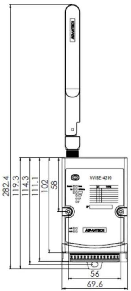

Figure 1.1 WISE-4210 Dimension Front & Side
1.3 System Diagram
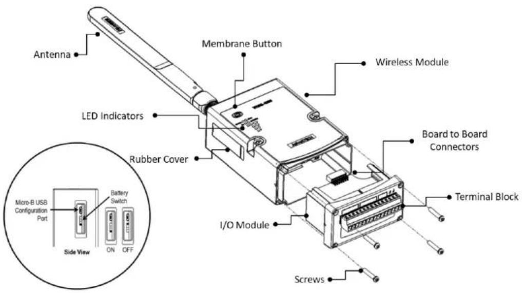
Figure 1.2 WISE-4210 System Diagram
1.4 LED Definition
1.4.1 WISE-4210-AP

Figure 1.3 WISE-4210-AP LED Indicator
LED Color Indication Behavior
| Status Green Blinking 0.5Hz: Operating normally | ||
| Error Red Blinking 2Hz: I/O error or RF related error | ||
| Rx Green Blinking Receiving data from LPWAN nodes | ||
| Tx Green Not Used | ||
| LAN Green | Blinking | 1Hz: Gateway's IP is available and is normally at work |
| On for 30 Sec | When enable LOCATE function | |
| COM Rx Green | Steady On | Receiving data from RS-485Turn on at last 10ms |
| Off | No data received from RS-485 | |
| COM Tx Yellow | Steady On | Sending data to RS-485Turn on at last 10ms |
| Off | No data sent to RS-485 | |
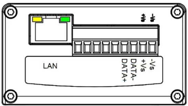
Figure 1.4 WISE-4210-AP LAN Port LED
| LED Color Indication Behavior | |
| Link Green | On Both ends of devices are connected |
| Off Not connected yet | |
| Speed Yellow | On 100 Mbps |
| Off Less than 100 Mbps | |
1.4.2 WISE-4210-S231

Figure 1.5 WISE-4210-S231 LED Indicator
| LED Color Indication Behavior | |||
| Status Green | Blink | 2 Hz: Initial Status0.5 Hz: Node is connected and nor-mally at work.(Automatically go OFF after 15 seconds when battery power is used.) | |
| On Site Survey mode | |||
| Off OTA mode (RF RX or RF TX on) | |||
| RF RX Green | On(at least 10 ms) Receiving data from the Gateway | ||
| On Listen RF channel | |||
| Off Idle | |||
| Rx Tx Yellow | On (at least 10 ms) | Sending data to the Gateway(Automatically be disabled after 15 seconds when battery power is used.) | |
| Off Idle | |||
| Error Red | Fast Blink | I/O ErrorOTA FailTX/RX Firmware fail in OTA | |
| Slow Blink | Low battery voltage | ||
| Off No error | |||
| Signal 4 Green | Fast Blink | RF related error | |
| Signal 3 Green | Fast Blink | IO error | |
| Signal Strength Green | On * 4 | Full signal(In site survy mode)Battery level (100%)(Automatically go OFF after 15 seconds when battery power is used.) | |
| On * 3 | Good signalBattery level (100%~50%)(same as above) | ||
| On * 2 | Okay signalBattery level (50%~30%)(same as above) | ||
| On * 1 | Poor signalBattery level (30%~0%)(same as above) | ||
| All Off | No signalBattery level (0%) | ||
All of LEDs will automatically go OFF after 15 seconds when battery power is used. RF RX and Signal Strength LEDs are only available in WISE Link v2 mode.
1.4.3 WISE-4210

Figure 1.6 WISE-4210 LED Indicator
| LED Color Indication Behavior | |||
| Status Green | Blink | 2 Hz: Initial Status0.5 Hz: Node is connected and nor-mally at work.(Automatically go OFF after 15 seconds when battery power is used.) | |
| On Site Survey mode | |||
| Off OTA mode (RF RX or RF TX on) | |||
| RF RX Green | On(at least 10 ms) Receiving data from the Gateway | ||
| On Listen RF channel | |||
| Off Idle | |||
| Rx Tx Yellow | On (at least 10 ms) | Sending data to the Gateway(Automatically be disabled after 15 seconds when battery power is used.) | |
| Off Idle | |||
| Error Red | Fast Blink | I/O ErrorOTA FailTX/RX Firmware fail in OTA | |
| Slow Blink | Low battery voltage | ||
| Off No error | |||
| Signal 4 Green | Fast Blink | RF related error | |
| Signal 3 Green | Fast Blink | IO error | |
| Signal Strength Green | On * 4 | Full signal(In site survy mode)Battery level (100%)(Automatically go OFF after 15 seconds when battery power is used.) | |
| On * 3 | Good signalBattery level (100%~50%)(same as above) | ||
| On * 2 | Okay signalBattery level (50%~30%)(same as above) | ||
| On * 1 | Poor signalBattery level (30%~0%)(same as above) | ||
| All Off | No signalBattery level (0%) | ||
All of LEDs will automatically go OFF after 15 seconds when battery power is used. RF RX and Signal Strength LEDs are only available in WISE Link v2 mode.
1.5 Membrane Button
WISE-4210-Sxxx end nodes have one membrane button on name plate. This button is design for switching different LED display mode or operation mode.
Note!WISE-4210-AP doesn't have membrane button, please use LAN port to do further configuration.


Figure 1.7 WISE-4210 Membrane Button
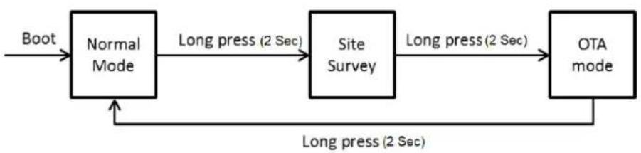
flowchart
graph LR
    A["Boot"] --> B["Normal Mode"]
    B --> C["Long press (2 Sec)"]
    C --> D["Site Survey"]
    D --> E["Long press (2 Sec)"]
    E --> F["OTA mode"]
    F --> G["Long press (2 Sec)"]
    G --> B
| Normal Mode | ||
| Mode Power Saving Mode Non-power saving Mode | ||
| Light Press (0.5 Sec) | LED turn on→Get battery level→LED turn off* | Get battery level→LED turn off* |
| Long Press (2 Sec) Leave normal mode Leave normal mode | ||
| Site Survey Mode | ||
| Light Press (0.5 Sec) Tx site survey packet | ||
| Long Press (2 Sec) Leave site survey mode | ||
| OTA Mode | ||
| Status Rx Status | Tx Status(by USB port) | Low Battery Update FW fail |
| Light Press (0.5 Sec) Read battery level | TxConfiguration | NA Reset OTA mode |
| Long Press (2 Sec) Leave OTA mode Tx Firmware Leave OTA mode NA | ||
*(LED indicator will go off automatically 15 secs later when using battery power.)
1.6 Battery Power Switch
Open the rubber cover on the side of WISE-4210-Sxxx nodes, there is a battery switch to turn on or turn off the battery power supply.
Note! This switch is only available for WISE-4210-Sxxx nodes, not for WISE-4210-AP.

This switch only controls the power supply from batteries. It did not control the power supply of line power from terminal block.

Figure 1.8 WISE-4210 Battery Switch
1.7 Package Information
WISE-4210-APNA/UA
■ 1 x WISE-4210-APNA/UA LPWAN IoT Wireless to Ethernet AP
1 x Mounting bracket
■ 1x China RoHS (UA series only)
■ 1x Antenna (UA series only)
WISE-4210-S231NA/UA
1 x WISE-4210-S231NA/UA LPWAN IoT Wireless module with temperature and humidity sensor
■ 1 x Mounting bracket
■ 1x China RoHS (UA series only)
■ 1x Antenna (UA series only)
WISE-4210 NA/UA
1 x WISE-4210 NA/UA module
1 x Mounting bracket
■ 1x China RoHS (UA series only)
■ 1x Antenna (UA series only)
WISE-S214-A
1x WISE-S214-A I/O Module
1x China RoHS
4x Screws
1x I/O sticker
WISE-S250-A
1x WISE-S250-A I/O Module
1x China RoHS
4x Screws
1x I/O sticker
WISE-S251-A
1x WISE-S251-A I/O Module
1x China RoHS
4x Screws
1x I/O sticker
Note!Antenna for NA series should be ordered respectively based on the required frequency range.

1750008836-01 863-870MHz Dipole Antenna for WISE-4210
1750008837-01 902-928MHz Dipole Antenna for WISE-4210
Note!Battery needs to order separately.

1760002647-01 3.6V/2500mAh AA Cylindrical Battery (non-rechargeable)
Note!Micro-B USB cable for configuring WISE-4210 nodes can be ordered optionally.

1700023619-01 1M micro USB type-B male to USB type-A male cable
Chapter 2
General Specification
2.1 General Specification
2.1.1 Wireless Interface
IEEE Standard
- IEEE 802.15.4g
- Operating Frequency
- NA923: 923MHz (920.8\~924.4), BW: 400KHz
– EU868: 868MHz (865.2\~868.8), BW:400KHz
Data Rate:
– WISE-4210-AP: 625 bps/ 2.5K bps / 5K bps / 50K bps
– WISE-4210 Node: 625 bps, 50K bps
Outdoor Range
- 625bps: 5 km (Line of sight)
- 50kbps: 2 km (Line of sight)
Antenna Gain
- 902\~928MHz: 1.48 dBi
- 863\~870MHz: 2.02 dBi
■ Transmit Power (CE): 14dBm±1dBm
■ Receiver Sensitivity:
- 115 dBm @ 625bps (Long-Rang Mode)
- 100 dBm @50Kbps
Topology: Star
■ Network Capacity: Up to 64 end nodes
Channel List:
| EU868BW: 400K Hz(Frequency: MHz) | NA915BW: 400K Hz(Frequency: MHz) | UN433BW: 300K Hz(Frequency: MHz) |
| Chanel 1 865.2 Chanel 1 920.8 Chanel 1 433.2 | ||
| Chanel 2 865.6 Chanel 2 921.2 Chanel 2 433.5 | ||
| Chanel 3 866.0 Chanel 3 921.6 Chanel 3 433.8 | ||
| Chanel 4 866.4 Chanel 4 922.0 Chanel 4 434.1 | ||
| Chanel 5 868.8 Chanel 5 922.4 Chanel 5 434.4 | ||
| Chanel 6 867.2 Chanel 6 922.8 | ||
| Chanel 7 867.6 Chanel 7 923.2 | ||
| Chanel 8 868.0 Chanel 8 923.6 | ||
| Chanel 9 868.4 Chanel 9 924.0 | ||
| Chanel 10 868.8 Chanel 10 924.4 | ||
Note!

The transmitting distance is subject to the environment of application site. Please perform site survey to determine the set up range of the wireless network.
2.1.2 General
■ Configuration Interface: Micro-B USB
Connector:
WISE-S200: Plug-in screw terminal block (I/O and power)
■ LED Indicator: Status, Error, Tx, Rx, Signal Level
■ Mounting: DIN35 rail, wall, pole and stack
■ Dimension (W x H x D): 70 x 112 x 38 mm
■ Certification: CE(RED), NCC, FCC, IC
I/O connector: 3.5-mm spacing plug-in screw terminal block
■ Power connector: 3.5-mm spacing plug-in screw terminal block
■ Real-time clock (RTC) accuracy: ±2 s/day
■ Enclosure: PC
Operation temperature: -20\~70°C (-4\~140°F)
■ Storage temperature: -40\~85°C (-40\~185°F)
- Operating humidity: 5\~95% RH (non-condensing)
■ Storage humidity: 0\~95% RH (non-condensing)
Note! Equipment will operate below 30% humidity. However, static electricity

problems occur much more frequently at lower humidity levels. Make sure you take adequate precautions when you touch the equipment.
Consider using ground straps, anti-static floor coverings, etc. if you use the equipment in low humidity environments.
Note! Measuring temperature and humidity will depend on sensor type.

Whether the device is measuring temperature or humidity depends on the settings of the sensors.
2.1.3 Power
■ Power input voltage: 10 \~ 50 V DC
■ Power consumption:
- WISE-4210-AP: 0.8 W @ 24 V _DC
- WISE-4210 Nodes: 0.3 W @ 24 V DC
■ Battery socket (WISE-4210 Nodes only, not for WISE-4210-AP)
AA 3.6VDC battery x 3 (parallel connection)
■ Battery life (2500mAh battery x3) @ 25°C:
- 625bps: 5 years with 10 minute update rate
- 50kbps: 5 years with 1 minute update rate
Note! The battery life is estimated with 2500mAh battery, SB-AA11 by Vitzrocell Co., Ltd.

Testing condition:
WISE-4210-S231: Temperature/Humidity sensor
■ WISE-4210-S251: Digital input only
Note! Power saving is not for downlink mode.

Note! The battery life is estimated in the environment at 25^ C. If the battery operated in low temperature, the battery life would be lower. Here is the estimation for battery SB-AA11 at different temperature:

■ SB-AA11 @ 0°C: Less than 30%
■ SB-AA11 @ -10°C: Less than 18%
■ SB-AA11 @ -25°C: Less than 13%
2.1.4 Software
Utility: WISE Studio
■ Driver: ADAM .NET Class Library
WISE-4210-AP Protocols: TCP/IP, UDP, HTTP, HTTPS, DHCP, ARP, SNTP
■ WISE-4210-AP supports RESTful Web API .JSON format
2.1.5 Configuration Interface
WISE-4210-AP
■ Interface: LAN port
Connector: RJ-45
WISE-4210 Nodes
■ Interface: USB virtual COM port
Connector: Micro-B USB
USB chipset: Silicon Labs CP210x
Driver: CP210x USB to UART Bridge VCP Drivers (https://www.silabs.com/products/development-tools/software/usb-to-uart-bridge-vcp-drivers)
2.2 WISE-4210-AP
2.2.1 Uplink Communication Port
LAN port
Ethernet: IEEE 802.3u 10/100Base-T(X)
Connector: 1-port RJ-45
■ Protocol: Modbus/TCP, RESTful web API
RS-485 port
Signal: DATA+, DATA-
- Connector: 3.5-mm spacing plug-in screw terminal block
Protocol: Modbus/RTU
2.2.2 Pin Assignment

Figure 2.1 WISE-4210-AP Pin Assignment
2.2.3 Block Diagram

flowchart
graph TD
    A["RF"] --> B["RF module with MCU"]
    C["LED"] --> B
    D["LED"] --> E["MCU"]
    F["Coin Battery"] --> E
    B <--> G["Power Converter"]
    E <--> H["Power Converter"]
    G <--> I["10~50V Power"]
    H <--> I
    E <--> J["LAN"]
    E <--> K["RS-485"]
    B <--> L["Communication Interface"]
Figure 2.2 WISE-4210-AP Block Diagram
2.3 WISE-4210-S231
2.3.1 I/O Specifications
Temperature Sensor Input
■ Operating Range: -25°C \~ 70°C (-4°F \~ 157.9°F)
■ Data Resolution: 0.1 (°C/°F/K)
■ Accuracy: ±2.0°C (Vertical Installation)
■ Update Rate: Minimum 1 second
■ Response Time: 15 seconds (Achieving 63% of a step function)
■ Long Term Drift: 0.05°C/Year (0.09°F/Year)
Humidity Sensor Input
■ Operating Range: 10\~90% RH
■ Resolution: 0.1% RH
Accuracy:
- ±4% for 0%\~50% RH
- ±6% for 50%\~60% RH
- ±10% for 60%\~90% RH
■ Update Rate: Minimum 1 second
■ Response Time: 10 seconds (Achieving 63% of a step function)
■ Long Term Drift: 0.5% RH/Year
2.3.2 Pin Assignment

natural_image
Technical line drawing of a rectangular electronic device with internal circuitry and mounting holes (no text or symbols)Figure 2.3 WISE-4210-S231 Pin Assignment
2.4 WISE-S214 (4AI/4DI)
2.4.1 I/O Specifications
Analog Input
Channels: 4
■ Resolution: 16bits Bipolar
15bits Unipolar
■ Sampling Rate:
1Hz (per Channel) with 50/60Hz Rejection (Power Saving Mode)
10Hz (Total) with 50/60Hz Rejection (Normal Mode)
Accuracy: ±0.1% for Voltage Input ±0.2% for Current Input
Input Range: 0\~150mV, 0\~500mV, 0\~1V, 0\~5V, 0\~10V, ±150mV, ±500mV, ±1V, ±5V, ±10V, 0\~20mA, ±20mA, 4-20mA
■ Input Impedance: >1MΩ (Voltage)
■ Isolated voltage: 3kVrms
■ Digital Input
– Channels: 4
■ Support Data Scaling and Averaging Digital Input Channels 4 (Dry Contact)
■ Supports 32-bit counter input function (maximum signal frequency 200Hz)
■ Supports keep/discard counter value on power-off
■ Support inverted digital input status
2.4.2 Pin Assignment
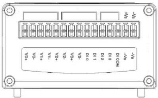
Figure 2.4 WISE-S214 Pin Assignment
2.5 WISE-S250 (6DI, 2DO& 1RS-485)
2.5.1 I/O Specifications
Digital Input
■ Channels: 6 (Dry Contact)
■ Supports 3kHz Frequency Input
Frequency mode
Counter mode
Digital Output (Sink Type)
Channels: 2
Output Current: 100 mA
- At 0 -> 1: 100 us
- At 1 -> 0: 100 us (for Resistive Load)
■ Supports Pules Output 5 kHz
Max. Load Voltage: 50V
Serial Port
■ Port Number: 1
Type: RS-485
Data Bits: 7, 8
■ Stop Bits: 1, 2
■ Parity: None, Odd, Even
Baud Rate (bps): 1200, 2400, 4800, 9600, 19200, 38400, 57600, 115200
Protocol: Modbus/RTU (Total 32 addresses by 8 max. instructions)
2.5.2 Pin Assignment
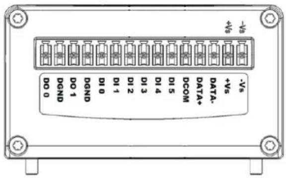
Figure 2.5 WISE-S250 Pin Assignment
2.6 WISE-S251 (6DI/1RS-485)
2.6.1 I/O Specifications
2.6.1.1 Digital Input
Channels: 6
■ Logic level (dry contact)
- 0: Open
- 1: Close DI COM
■ Supports 32-bit counter input function (maximum signal frequency, 200Hz)
■ Supports keep/discard counter value on power-off
■ Supports inverted digital input status
2.6.1.2 RS-485 Port
■ Port Number: 1
Type: RS-485
Data Bits: 7, 8
- Stop Bits: 1, 2
■ Parity None, Odd, Even
Baud Rate (bps): 1200, 2400, 4800, 9600, 19200, 38400, 57600, 115200
■ Protocol: Modbus/RTU (Total 32 address by max. 8 instructions)
2.6.2 Pin Assignment
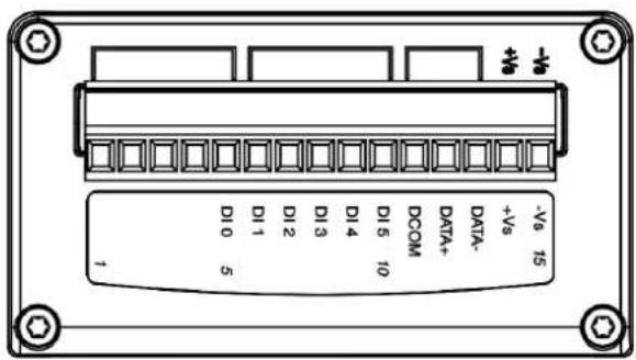
Figure 2.6 WISE-S251 Pin Assignment
2.6.3 Application Wiring
WISE-S214
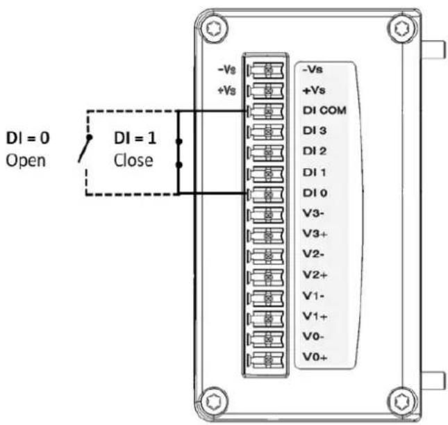
Figure 2.7 WISE-S214 Digital Input Wiring Diagram
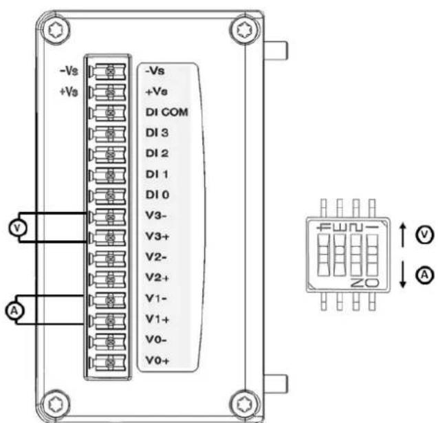
Figure 2.8 WISE-S214 Analog Input Wiring Diagram
WISE-S250
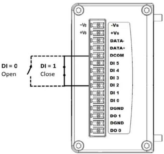
Figure 2.9 WISE-S250 Digital Input Wiring Diagram

Figure 2.10 WISE-S250 Digital Output Wiring Diagram

Figure 2.11 WISE-S250 RS-485 Wiring Diagram
WISE-S251
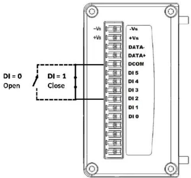
Figure 2.12 WISE-S251 Digital Input Wiring Diagram
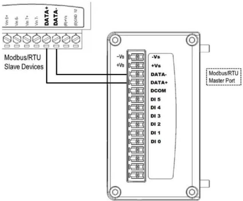
Figure 2.13 WISE-S251 RS-485 Wiring Diagram
2.7 WISE-4210 Node Block Diagram
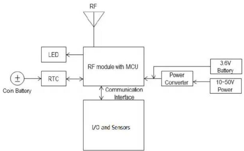
flowchart
graph TD
    A["Coin Battery"] --> B["RTC"]
    B --> C["RF module with MCU"]
    C --> D["LED"]
    C --> E["Power Converter"]
    D <--> C
    E <--> C
    F["I/O and Sensors"] --> G["Communication Interface"]
    H["RF"] --> C
    I["3.6V Battery"] --> E
    J["10-50V Power"] --> E
Figure 2.14 WISE-4210 Node Block Diagram
Chapter 3
Hardware Installations
The wireless sensor nodes for WISE-4210, like those for all WISE-4000 series modules, are designed as separate units. The procedure for installing these nodes in the module is explained in the following sections.
3.1 Modular Design
WISE-4210 features a modular design that supports various I/O configurations. The benefit of a modular design is that the same wireless board can be leveraged by different I/O modules via a board-to-board connector. This allows users to install two I/O modules according to their specific usage requirements. Moreover, the modules can be affixed to WISE-4210 using the six screws provided (as shown in Figure 3.1).
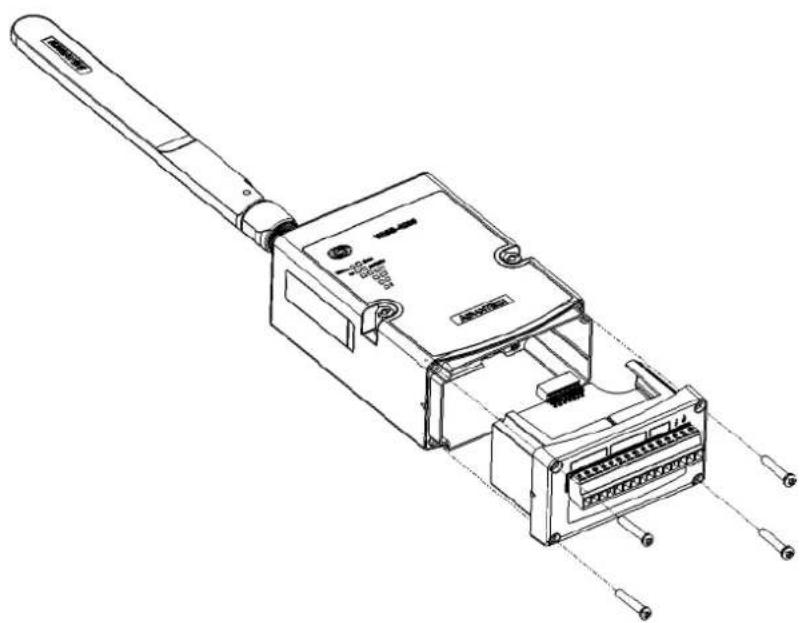
natural_image
Technical line drawing of an electronic device with internal components and connectors (no text or symbols)Figure 3.1 I/O Module Installation
3.2 Interface Introduction

Figure 3.2 WISE-4210 Interface Introduction
3.3 Mounting
Like all WISE-4000 series modules, the WISE-4210 series of wireless sensor nodes are designed as compact units. Applicable installation methods are briefly described in the following sections.
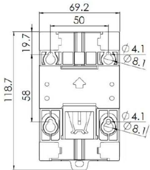
Figure 3.3 WISE-4000 Series Mounting Kit Dimensions
3.3.1 DIN-Rail Mounting
WISE-4210 modules can be fixed to a cabinet with mounting rails. Use a flathead screwdriver to fasten the DIN rail adapter to your module. You can then use the end brackets included in the package in order to keep it from sliding.
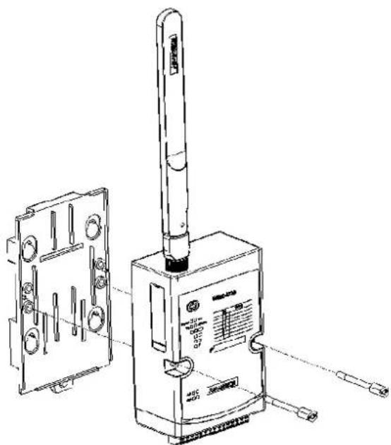
Figure 3.4 DIN-rail Mounting Installation
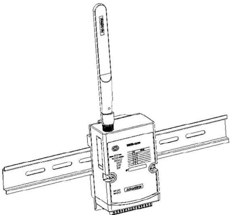
natural_image
Technical line drawing of a satellite or radar device with a vertical sensor mounted on its body (no text or symbols visible)Figure 3.5 DIN-rail Mounting (front)
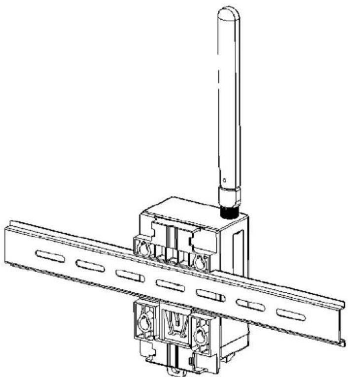
natural_image
Technical line drawing of a mechanical assembly with a vertical rod and mounting bracket (no text or symbols)Figure 3.6 DIN-rail Mounting (back)
3.3.2 Wall Mounting
The plastic wall-mounting bracket that comes with the module can be used to mount it on a wall, panel, or cabinet.
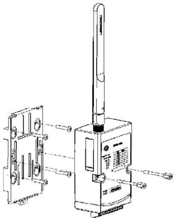
natural_image
Technical line drawing of a handheld device with internal components and mounting brackets (no text or symbols)Figure 3.7 Wall Mounting Installation
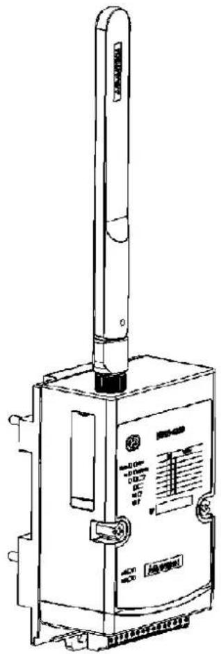
natural_image
Technical line drawing of a mechanical device with a vertical rod and control panel (no text or symbols)Figure 3.8 Wall Mounting Installation
3.3.3 Pole Mounting
Put the pole mounting ring through the middle hole. Note that you should unlock the pole mounting ring with a screw driver before mounting. Mount the WISE-4200 module steadily onto the pole by locking the pole mounting ring tightly.
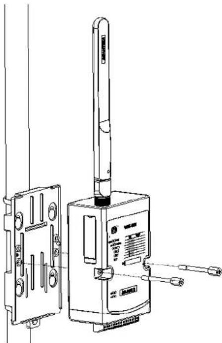
natural_image
Technical line drawing of a device with attached components and a vertical rod (no text or symbols)Figure 3.9 Pole Mounting (front)
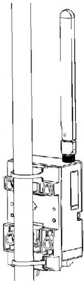
natural_image
Technical line drawing of a mechanical device with cylindrical components and mounting features (no text or symbols)Figure 3.10 Pole Mounting (back)
3.4 Wiring and Connections
This section provides basic information on wiring the power supply and I/O units.
3.4.1 Power Supply Wiring
WISE-4210 modules are designed to support a standard industrial unregulated 24- V_DC power supply. For other applications, they can also accept +10 to +50 V_DC input with 200 mV of peak-to-peak power ripple. The immediate ripple voltage should be maintained between +10 and +50 V_DC . The screw terminals labeled "+Vs" and "-Vs" are for the power supply wiring.

Figure 3.11 WISE-4210-AP Power Wiring
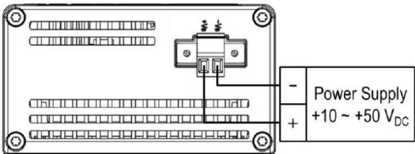
Figure 3.12 WISE-4210-S231 Power Wiring
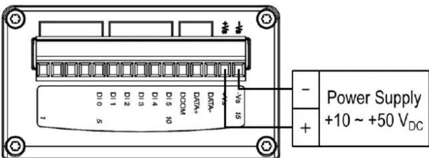
Figure 3.13 WISE-S200 Power Wiring
3.4.2 Battery Installation
Open the battery cover on the back of module. There are 3 battery sockets for 3.6 VDC AA batteries. Since the batteries are parallel connection, batteries are installed in same direction, positive pole (+) on left and negative pole (-) on right.
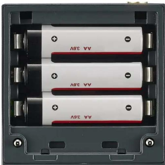
natural_image
Interior view of a battery pack with three white batteries each labeled with 'AA 3.6V' and red leads, showing no additional text or symbols.Figure 3.14 WISE-4210 Battery Socket
Open the rubber cover on the side of WISE module, there is a battery switch to turn on or turn off the battery power supply.
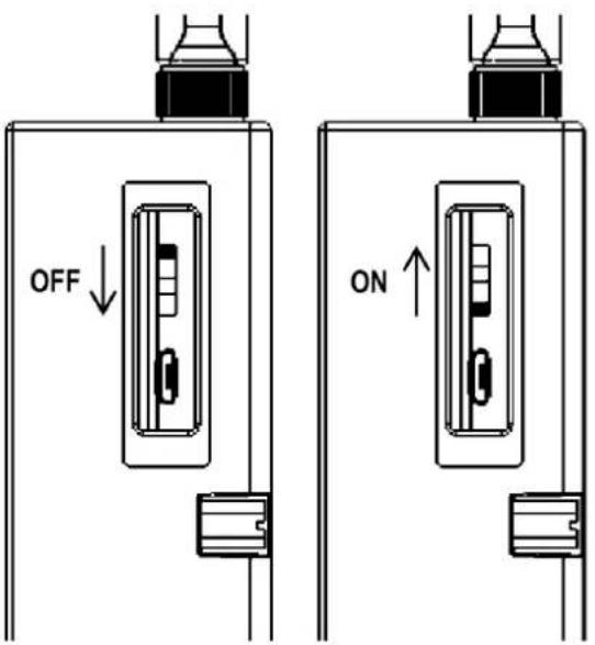
Figure 3.15 WISE-4210 Battery Switch
Note! This switch is only available for WISE-4210 nodes, not for WISE-4210-AP.

Note!Battery needs to order separately

1760002647-01 3.6V/2500mAh AA Cylindrical Battery (non-rechargeable)
3.4.3 I/O Units
WISE-4210 uses a plug-in screw terminal block for the interface between WISE-4210 and field devices. The following information is critical when connecting electrical devices to I/O modules.
■ Use the correct wire gauge (note that the terminal block accepts wires from 0.5 to 2.5 mm)
■ Use a continuous length of wire (do not join separate wires to form a continuous length)
■ Use the shortest wire length possible
■ Use wire trays for routing wherever possible
■ Avoid running wires near to high-energy wiring
■ Avoid running input wiring near output wiring
■ Avoid creating sharp bends or kinks in the wires
Chapter 4
System Configuration
4.1 Connection
4.1.1 WISE-4210-AP Connection
WISE-4210 uses the RJ-45 LAN port for configuration. Connect your computer to Ethernet port of the WISE module with RJ-45 cross-over Ethernet cable, and configure the IP address of your computer as same IP domain as default IP address of module: 10.0.0.1
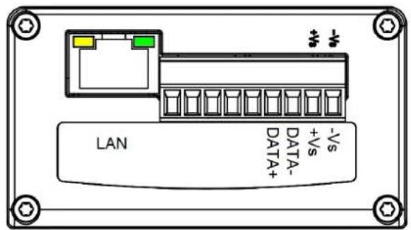
Figure 4.1 WISE-4210-AP LAN port
4.1.2 WISE-4210-Sxxx Node Connection
WISE-4210-Sxxx node uses the micro-B USB port for configuration. After removing the rubber cover on the side of the WISE module, there is a micro-B connector. Connect this port to the computer's USB port for configuration. The USB driver would be needed for creating a virtual COM port on the computer. Please refer to the following link to get the latest USB driver: CP210x USB to UART Bridge VCP Drivers (https://www.silabs.com/products/development-tools/software/usb-to-uart-bridge-vcp-drivers)

Figure 4.2 USB configuration port of WISE-4210 node
Note! Micro-B USB cable for configuring WISE-4210 nodes is available for ordered:
1700023619-01 1M micro USB type-B male to USB type-A male cable

4.2 Configuring WISE-4210-AP with Browser
4.2.1 System Requirements
The web utility of WISE-4210-AP is developed with public HTML 5, but for detailed information and data transmission mode, the type of web utility will depend on the web page of the operating system.
For mobile devices, the minimum system requirements of web browsers are as below:
■ Safari 6 in Apple iOS
■ Web Browser in Google Android 4.0 (Ice Cream Sandwich)
Chrome in Google Android 4.0 (Ice Cream Sandwich)
Mobile Browser Chrome Android Safari
| Configuration Y | Y | Y | |
| File Upload | N | N | N |
| Data Log Chart | Y | Y | Y |
| Data Log Export | N | N | N |
For PC platforms, the minimum requirements of web browsers are as below:
■ Internet Explorer (version 11)
■ Google Chrome (version 30)
■ Mozilla Firefox (version 25)
| Mobile Browser | Chrome | Firefox | Safari | IE11 | IE10 |
| Configuration | Y | Y | Y | Y | Y |
| File Upload | Y | Y | N | Y | N |
| Data Log Chart | Y | Y | Y | Y | Y |
| Data Log Export | Y | Y | N | N | N |
4.2.2 Factory Default Settings
IP Mode: Static IP Address
Default IP: 10.0.0.1
■ Subnet Mask: 255.0.0.0
■ Default Gateway: 0.0.0.0
IP Mode: Static
HTTP Port: 80
4.2.3 Module Authorization
| Account | Default Password | Access Ability |
| root | 00000000 | All privileges |
| admin | 00000000 | All privileges except access control configuration |
| user | 00000000 | View module status only.Not allow to change configurations |
Functions Account
| root admin user | |
| Device information View View View | |
| Device setting Edit Edit Deny | |
| System Restart Edit Edit Edit | |
| Module Locate Edit Edit Edit | |
| Change passwords Edit Deny Deny | |
| Reset Password Edit Deny Deny | |
| Reset to default Edit Deny Deny | |
| Access control configurations | Edit Edit Deny |
| Group configurations | Edit Edit Deny |
| Download/upload processes | Edit Edit Deny |
| Network configurations | Edit Edit View |
| I/O configurations | Edit Edit View |
| I/O statuses monitor View View View | |
| Reset AI calibration to default | Edit Deny Deny |
| MODBUS addresses | Edit Edit View |
| Data log configuration and query | Edit Edit View |
| Clear data log | Edit Edit Deny |
4.3 Install WISE Studio and Configure End Devices
Step 1. Download and install WISE Studio through:
https://support.advantech.com/support/new_default.aspx
Step 2. Execute WISE Studio
Step 3. Power up WISE-4210 using batteries or line power.
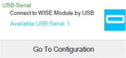
Step 4. Use a USB cable to communicate between WISE-4210 and the computer. (Please take note the USB cable is not able to power up the device.)
Step 5. Click "Go to Configuration" where it shows "available USB-Serial" in USB-Serial box. (If the device cannot be connected through USB, please install CP210x USB to UART Bridge VCP Drivers from the following website:
https://www.silabs.com/products/development-tools/software/usb-to-uart-bridge-vcp-drivers)
Step 6. Click "Connect" to access the end device.

Step 7. Once everything is all set, you should be successfully into the configuration page.
4.4 Connection between AP and Nodes
The first step of the connection between WISE-4210 end node devices and WISE-4210-AP is to configure the units in the same network with the same frequency range. Please go to "End Devices \ RF Status \ Configuration" to configure the RF module by following the instructions below.
RF Operation Mode: WISE-4210 end node devices support "Push Mode", communication from the end node device to AP is uplink only, no downlink.
Data Rate (bps): Lower data rate is helpful of extending communication range, while higher data rates can reduce the communication time which allows more data to be uploaded to AP in the same period of time.
- Tx Power (dBm): Lower Tx power helps to reduce the power consumption and extend longer battery life; higher Tx power enhances the communication distance.
Baseband (kHz): If several WISE-4210-AP or sub-GHz networks are in the same area, users can select different base bands to reduce the interference of each network. Note that each WISE-4210 end node devices in the same network should use the same baseband as WISE-4210-AP.

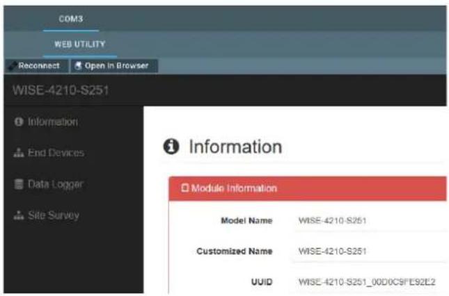
Device: WISE-4210-S251

Once the network configuration is finished, go to "End Devices \ IO Status" for I/O function configuration.

4.5 WISE-4210-AP Configuration
Step 1. The default IP address of WISE-4210-AP is 10.0.0.1, if you are not able to access WISE-4210-AP, please follow the steps below to search the IP address of WISE-4210-AP.
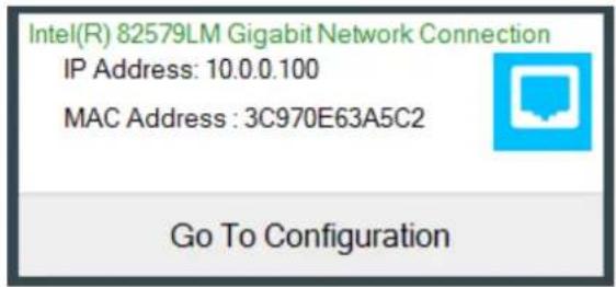
Step 2. Configure the Ethernet adapter to 10.0.0.1 IP address. In the following figure, the IP address is configured as 10.0.0.100. Find the Ethernet box in WISE Studio, and click "Go to Configuration"
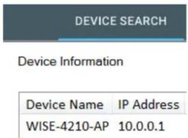
Step 3. After the above steps, WISE Studio will search WISE-4210-AP, and you will see the IP address on the Device Information screen.
Step 4. Enter the IP address of WISE-4210-AP in the browser, or you can keep using WISE Studio to make further configurations.
The default account and password of WISE-4210-AP to log into the web page is root and 00000000. Cick "Login".

Step 5. Go to "Configuration \ Network" to configure LAN port parameters of WISE-4210-AP.

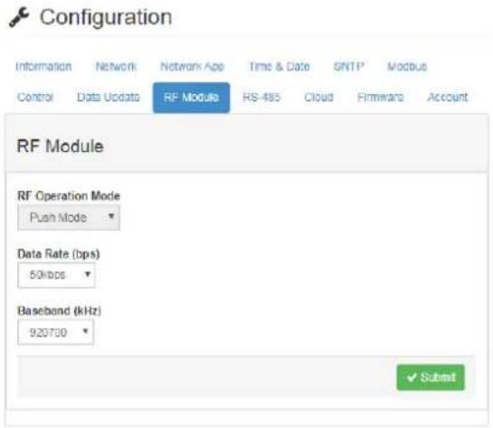
Step 6. Go to "Configuration \ RF Module" to configure the RF module.
RF Operation Mode: WISE-4210 end node devices support "Push Mode", communication from the end node device to AP is uplink only, no downlink.
Data Rate (bps): Lower data rates are helpful for extending communication ranges, while higher data rates can reduce the communication time which allows more data to be uploaded to AP in the same period of time.
Baseband (kHz): If several WISE-4210-AP or sub-GHz networks are in the same area, users can select different base bands to reduce the interference of each network. Note that each WISE-4210 end node device in the same network should use the same baseband as WISE-4210-AP.
4.6 Setup WISE-4210 Network
After configuring all end devices into the network with WISE-4210-AP, users can go to "End Devices" tab to see "End Device List".
■ MAC Address: The unique identifier of each end device.
Modbus ID: Modbus ID is automatically assigned by WISE-4210-AP. User can configure Modbus ID manually in "Configuration \ Modbus \ Modbus ID".
■ RSSI (dBm): Signal strength when data updated from end device to AP. RSSI will be updated when WISE-4210-AP is receiving data from end node devices. It is suggested RSSI is higher than -100dBm.
Inactive Time: Elapsed time since WISE-4210-AP received data from the end node devices. If end node devices update data every 5 seconds and they have good wireless signal quality, Inactive Time will go back to 0 or 1 every 5 seconds.

End Device List
| MAC Address | Modbus ID | RSSI | Inactive Time | Battery Status | Battery Level | RTC Battery Status | Power Source | Device Status |
| 4B0012CD11AC | 1 | -71 | 2 | No Error | 100 % | No Error | Line power, Device battery | Active |
| 4B0012CC4166 | 2 | -72 | 4 | No Error | 100 % | No Error | Line power, Device battery | Active |
| 4B0012CD140B | 3 | -62 | 2 | No Error | 100 % | No Error | Line power, Device battery | Active |
4.7 Access WISE-4210 I/O Data by Modbus/TCP Protocol
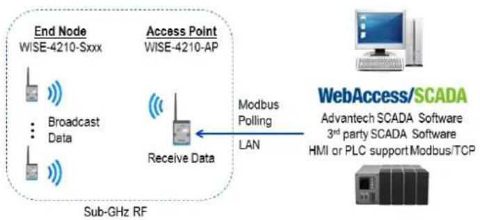
flowchart
graph LR
    A["End Node WISE-4210-Sxxx"] --> B["Broadcast Data"]
    B --> C["Receive Data"]
    C --> D["WebAccess/SCADA\nAdvantech SCADA Software\n3rd party SCADA Software\nHMI or PLC support Modbus/TCP"]
    D --> E["Modbus Polling LAN"]
    E --> C
    style A fill:#f9f,stroke:#333
    style B fill:#ccf,stroke:#333
    style C fill:#cfc,stroke:#333
    style D fill:#fcc,stroke:#333
    style E fill:#cff,stroke:#333
Go to "Configuration \ Modbus \ Modbus ID" to check MAC address of AP and each end node device, and to configure the Modbus ID. Use Modbus/TCP protocol to access each end device by WISE-4210-AP, polling different Modbus ID for different end node devices, or AP.

Configuration
Information
Network
Network App
Time & Date
SNTP
Modbus
Control
Data Update
RF Module
RS-485
Cloud
Firmware
Account
Modbus Address
Modbus ID
Modbus ID
AP
Modbus ID
241
End Devices
| End Device MAC | Modbus ID | |
| 4B0012CC4166 | 2 | Delete |
| 4B0012CD140B | 3 | Delete |
| 4B0012CC414D | 4 | Delete |
| 4B0012CD11EB | 5 | Delete |
| 4B0012CD11AC | 1 | Delete |
| 4B0012CD1427 | 6 | Delete |
| 4B0008FB79A1 | 7 | Delete |

Submit

Delete All End Devices
- Modbus Address Table for WISE-4210-S231
Modbus Address Sensor Input
40501 Temperature
40502 Humidity
45302 RSSI (-dBm)
- Modbus Address Table for WISE-4210-S250
| Modbus Address I/O |
| 00001 DI0 |
| 00002 DI1 |
| 00003 DI2 |
| 00004 DI3 |
| 00005 DI4 |
| 00006 DI5 |
| 01001~01032 RS-458 Coils |
| 41001~41032 RS-458 Registers |
| 45302 RSSI (-dBm) |
4.8 Push WISE-4210 data by RESTful Web Service
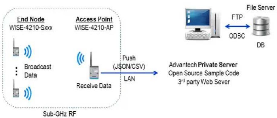
flowchart
graph LR
    A["End Node\nWISE-4210-Sxxx"] --> B["Access Point\nWISE-4210-AP"]
    B --> C["Receive Data"]
    C --> D["Push (JSON/CSV)\nLAN"]
    D --> E["Advantech Private Server\nOpen Source Sample Code\n3rd party Web Sever"]
    E --> F["File Server"]
    F --> G["DB"]
    H["Sub-GHz RF"] --> C
    I["FTP"] --> F
    J["ODBC"] --> F
Step 1. Configure the Private Server in "Configuration \ Cloud"
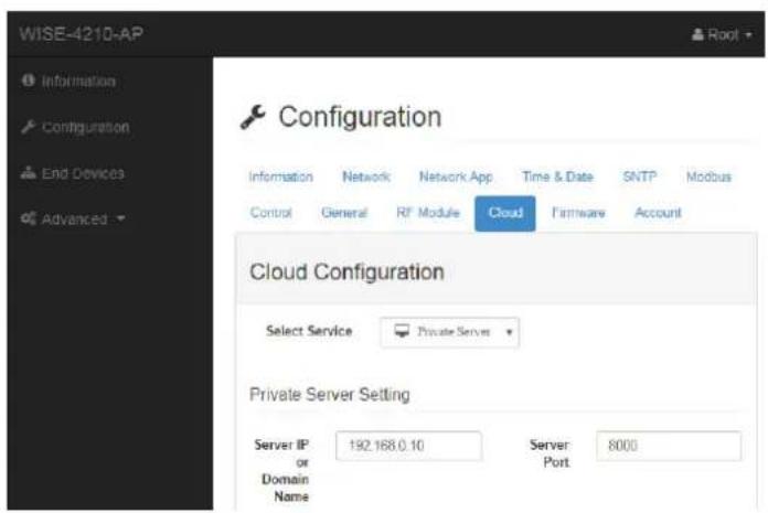
Step 2. Enable the Data Logger function in "Advanced \ Data Logger \ Logger Configuration"

4.9 Access WISE-4210 I/O Data by RESTful API
/lpwan_message/slot_macID
Description Retrieves the log data in system memory.

URL Structure http://10.0.0.1/lpwan_message/slot_macID

HTTP Method GET: According to the setting of filtering, server returns the all/partial of push data.

Request:
GET / lpwan_message/slot_macID

[Example]:
■ Request : GET /lpwan_message/slot_AD4210112233 for WISE-4210 module

Content-type: application/json
Response: 200 OK
{
    "TIM": "2014-11-11T15:48:32+08:00",
    "UID": "WISE-4210-AP_00D0C90E8738",
    "MAC": "00-D0-C9-FE-16-01",
    "Rssi": -33,
    "Record": [
    [0,0,1,0],
    [0,0,2,50],
    [0,0,3,10],
    [0,1,4,0],
    [0,1,5,456],
    [0,1,6,0],
    [0,0,30,0],
    [0,0,31,16],
    [0,0,32,32767]
]
}
■ JSON array name definition:
Field Abbreviation Data Type
Array of I/O records Record Array
■ Resource value definitions:
Field Abbreviation Data Type Property Description
| Timestamp of the storage– Coordinated Universal Time (UTC) | ||||
| Ex. "1415757750" corresponds to November 12, 2014, 2:02:30 am, Standard Time. (meanwhile, 2014, 10:02:30 am, Taipei Time.) | ||||
| Timestamp TIM String R | – Local Date/Time according GMT time zone (ISO 8601) | |||
| Ex. "1994-11-05T08:15:30-05:00" corresponds to November 5, 1994, 8:15:30 am, US Eastern Standard Time. | ||||
| UUID UID String R | Universally Unique Identifier (UUID) Max. 32 characters | |||
| MAC ID MAC String R | MAC address, ex, "00-D0-C9-F0-63-F7" | |||
| RSSI Rssi Number | R | The RSSI value | ||
| Recording message | Record | Array | R | * The data type in array is as follows. [Number, Number, Number, Number]* The information in array is as follows. [Slot-index, Channel-index, I/O-type-index, I/O-value]* See I/O Type Index Table for I/O type-index |
Index Recording I/O-type of the storage
| 0 Invalid |
| 1 DI Logic Status |
| 2 DI Counter value |
| 3 DI Frequency value |
| 4 DO Logic Status |
| 5 DO Absolute Pulse Output value |
| 6 DO Incremental Pulse Output Value |
| 7 AI value |
| 8 Historical Maximum AI value |
| 9 Historical Minimum AI value |
| 10 AI value after scaling |
| 11 AI status flags |
| 12 AI engineering value |
| 13 Historical Maximum AI engineering value |
| 14 Historical Minimum AI engineering value |
| 24 DI period (counter mode) |
| 25 DI low-to-high trigger tick |
| 30 Expansion bit data |
| 31 Expansion bit error code |
| 32 Expansion word data |
| 33 Expansion word error code |
| 40 Sensor engineering value |
| 41 Sensor maximum engineering value |
| 42 Sensor minimum engineering value |
| 43 Sensor status |
| 44 Sensor alarm status |
www.advantech.com
Please verify specifications before quoting. This guide is intended for reference purposes only.
All product specifications are subject to change without notice.
No part of this publication may be reproduced in any form or by any means, electronic, photocopying, recording or otherwise, without prior written permission of the publisher.
All brand and product names are trademarks or registered trademarks of their respective companies.
© Advantech Co., Ltd. 2020

- Acknowledgements
- Product Warranty (2 years)
- Declaration of Conformity
- FCC Class A
- Technical Support and Assistance
- Warnings, Cautions and Notes
- Document Feedback
- Package List
- WISE-4210-APNA/UA
- WISE-4210-S231NA/UA
- WISE-4210 NA/UA
- WISE-S214-A
- WISE-S250-A
- WISE-S251-A
- Safety Instructions
- Safety Precaution - Static Electricity
- NCC 警语
- Industry Canada statement:
- Contents
- Chapter 1 Product Overview....1
- Chapter 2 General Specification......13
- Chapter 3 Hardware Installations.... 27
- Chapter 4 System Configuration.... 39
- Chapter 1
- Series Family and Specifications
- Mechanical Design and Dimensions
- System Diagram
- LED Definition
- WISE-4210-AP
- WISE-4210-S231
- WISE-4210
- Membrane Button
- Battery Power Switch
- Package Information
- Chapter 2
- General Specification
- Wireless Interface
- General
- Power
- Software
- Configuration Interface
- WISE-4210-AP
- WISE-4210 Nodes
- WISE-4210-AP
- Uplink Communication Port
- LAN port
- RS-485 port
- Pin Assignment
- Block Diagram
- WISE-4210-S231
- I/O Specifications
- Temperature Sensor Input
- Humidity Sensor Input
- Pin Assignment
- WISE-S214 (4AI/4DI)
- I/O Specifications
- Pin Assignment
- WISE-S250 (6DI, 2DO& 1RS-485)
- I/O Specifications
- Pin Assignment
- WISE-S251 (6DI/1RS-485)
- I/O Specifications
- Digital Input
- RS-485 Port
- Pin Assignment
- Application Wiring
- WISE-4210 Node Block Diagram
- Chapter 3
- Modular Design
- Interface Introduction
- Mounting
- DIN-Rail Mounting
- Wall Mounting
- Pole Mounting
- Wiring and Connections
- Power Supply Wiring
- Battery Installation
- I/O Units
- Chapter 4
- Connection
- WISE-4210-AP Connection
- WISE-4210-Sxxx Node Connection
- Configuring WISE-4210-AP with Browser
- System Requirements
- Factory Default Settings
- Module Authorization
- Install WISE Studio and Configure End Devices
- Connection between AP and Nodes
- WISE-4210-AP Configuration
- Setup WISE-4210 Network
- Access WISE-4210 I/O Data by Modbus/TCP Protocol
- Configuration
- Push WISE-4210 data by RESTful Web Service
- Access WISE-4210 I/O Data by RESTful API
- www.advantech.com
Brand : Advantech
Model : WISE-4210-APNA
Category : Unspecified