
VNM Enterprise Controller - Controller Extron - Free user manual and instructions
Find the device manual for free VNM Enterprise Controller Extron in PDF.


| Product Type | Enterprise Controller for VN-Matrix Systems |
| Brand | Extron |
| Model | VNM Enterprise Controller |
| Dimensions (W x H x D) | 17.0" x 1.7" x 10.5" (approximate, 1U rack mount) |
| Weight | Approximately 10 lbs (4.5 kg) |
| Power Supply | 100-240 VAC, 50/60 Hz, internal power supply |
| Default IP Address | 192.168.254.254 |
| Default Subnet Mask | 255.255.255.0 |
| Network Interface | Two Ethernet ports: eth0 (primary network), eth1 (cluster/redundancy) |
| Front Panel Features | Power button, Reset button, CD/DVD drive (or CompactFlash), USB ports, Status LEDs (Power, Drive Activity, Network Activity, Overheat) |
| Rear Panel Connectors | IEC power connector, VGA, PS/2 mouse/keyboard, COM1 serial, USB, two Ethernet (eth0, eth1) |
| Redundancy Support | Dual (redundant) controller configuration with cluster IP and crossover cable |
| Transport Protocols | Multicast RTP, Unicast RTP, Unicast TCP |
| Maximum Managed Devices | Supports large deployments (over 10 devices recommended) |
| Web-Based User Interface | Full device management, preset configuration, monitoring, and firmware updates |
| Preset Management | Create, save, and recall presets with connection rules and device attributes |
| HLI Support | High-Level Interface for third-party control via Ethernet or serial |
| Firmware Update | Via Upgrade page in web UI; supports single and redundant controller updates |
| Compatible Devices | VN-Matrix encoders, decoders, codecs, VNM recorders, VNR 100, VNS 104 software decoder |
| Operating Temperature | 32°F to 122°F (0°C to 50°C) typical |
| Safety | FCC Class A, CE; follow Extron Safety and Regulatory Compliance Guide |
| Warranty | 3 years parts and labor |
Frequently Asked Questions - VNM Enterprise Controller Extron
User questions about VNM Enterprise Controller Extron
0 question about this device. Answer the ones you know or ask your own.
Ask a new question about this device
Download the instructions for your Controller in PDF format for free! Find your manual VNM Enterprise Controller - Extron and take your electronic device back in hand. On this page are published all the documents necessary for the use of your device. VNM Enterprise Controller by Extron.
USER MANUAL VNM Enterprise Controller Extron
VNM Enterprise Controller
VN-Matrix® Enterprise Controller

natural_image
Extron VNM Enterprise Controller rack with ports and connectors (no readable text or symbols beyond branding)Safety Instructions
Safety Instructions • English
WARNING: This symbol, , when used on the product, is intended to alert the user of the presence of uninsulated dangerous voltage within the product's enclosure that may present a risk of electric shock.
ATTENTION: This symbol, when used on the product, is intended to alert the user of important operating and maintenance (servicing) instructions in the literature provided with the equipment.
For information on safety guidelines, regulatory compliances, EMI/EMF compatibility, accessibility, and related topics, see the Extron Safety and Regulatory Compliance Guide, part number 68-290-01, on the Extron website, www.extron.com.
© 2016-2019 Extron Electronics. All rights reserved.
Trademarks
All trademarks mentioned in this guide are the properties of their respective owners. The following registered trademarks ^® , registered service marks ^SM , and trademarks ^TM are the property of RGB Systems, Inc. or Extron Electronics (see the current list of trademarks on the Terms of Use page at www.extron.com):
| Registered Trademarks ^® |
| Extron, AVTrac, Cable Cubby, ControlScript, CrossPoint, DTP, eBUS, EDID Manager, EDID Minder, Flat Field, FlexOS, Global Configurator, Global Scripter, GlobalViewer, Hideaway, Inline, IP Intercom, IP Link, Key Minder, LinkLicense, LockIt, MediaLink, MediaPort, NetPA, PlenumVault, PoleVault, PowerCage, PURE3, Quantum, SoundField, SpeedMount, SpeedSwitch, System INTEGRATOR, TeamWork, TouchLink, V-Lock, VersaTools, VN-Matrix, VoiceLift, WallVault, WindoWall, XTP, and XTP Systems |
| Registered Service Mark ^(SM) : S3 Service Support Solutions |
| Trademarks ^(TM) |
| AAP, AFL (Accu-Rate Frame Lock), ADSP (Advanced Digital Sync Processing), Auto-Image, CableCover, CDRS (Class D Ripple Suppression), DDSP (Digital Display Sync Processing), DMI (Dynamic Motion Interpolation), Driver Configurator, DSP Configurator, DSVP (Digital Sync Validation Processing), eLink, EQIP, FastBite, FOX, FOXBOX, IP Intercom HelpDesk, MAAP, MicroDigital, Opti-Torque, ProDSP, QS-FPC (QuickSwitch Front Panel Controller), Room Agent, Scope-Trigger, ShareLink, SIS, Simple Instruction Set, Skew-Free, SpeedNav, Triple-Action Switching, True4K, Vector ^TM 4K , WebShare, XTRA, ZipCaddy, and ZipClip |
FCC Class A Notice
This equipment has been tested and found to comply with the limits for a Class A digital device, pursuant to part 15 of the FCC rules. The Class A limits provide reasonable protection against harmful interference when the equipment is operated in a commercial environment. This equipment generates, uses, and can radiate radio frequency energy and, if not installed and used in accordance with the instruction manual, may cause harmful interference to radio communications. Operation of this equipment in a residential area is likely to cause interference. This interference must be corrected at the expense of the user.
NOTE: For more information on safety guidelines, regulatory compliances, EMI/EMF compatibility, accessibility, and related topics, see the "Extron Safety and Regulatory Compliance Guide" on the Extron website.
Battery Notice
This product contains a battery. Do not open the unit to replace the battery. If the battery needs replacing, return the entire unit to Extron (for the correct address, see the Extron Warranty section on the last page of this guide).
CAUTION: Risk of explosion. Do not replace the battery with an incorrect type. Dispose of used batteries according to the instructions.
Conventions Used in this Guide
Notifications
The following notifications are used in this guide:
CAUTION: Risk of minor personal injury.
NOTE: A note draws attention to important information.
TIP: A tip provides a suggestion to make working with the application easier.
Software Commands
Commands are written in the fonts shown here:
^AR Merge Scene,,Op1 scene 1,1 ^B 51 ^W^C [∅1] R∅004∅03∅0∅04∅0∅08∅0∅06∅0 [∅2] 35 [17] [∅3]
Esc X1 * X17 * X20 * X23 * X21 CE ←
NOTE: For commands and examples of computer or device responses mentioned in this guide, the character "0" is used for the number zero and "0" is the capital letter "o."
Computer responses and directory paths that do not have variables are written in the font shown here:
Reply from 208.132.180.48: bytes=32 times=2ms TTL=32 C:\Program Files\Extron
Variables are written in slanted form as shown here:
ping xxx.xxx.xxx.xxx -t SOH R Data STX Command ETB ETX
Selectable items, such as menu names, menu options, buttons, tabs, and field names are written in the font shown here:
From the File menu, select New. Click the OK button.
Specifications Availability
Product specifications are available on the Extron website, www.extron.com.
Extron Glossary of Terms
A glossary of terms is available at http://www.extron.com/technology/glossary.aspx.
Contents
Introduction 1
About this Guide....1
About the VNM Enterprise Controller .... 1
About the Web-based User Interface....2
About Dual (Redundant)
VNM Enterprise Controllers....3
Transport Protocols Used for Streaming 4
Multicast RTP — An Overview 4
Unicast RTP — An Overview 5
Unicast TCP — An Overview 5
Definitions....6
Features 6
Panels and Cabling....7
Installation Overview 7
Front Panel Features....7
Rear Panel Features 9
Controller Configuration and Operation.....10
Power Up Procedure 10
Web-based User Interface Overview......10
Accessing the Web-based User Interface ..... 11
Power Down Procedure.... 12
Single Enterprise Controller
Configuration....13
Setup Overview 13
Single VNM Enterprise Controller
Configuration....14
Configuring the Network Settings 14
Setting the Role....15
Configuring the Transport Protocol.... 16
Configuring a Single Enterprise Controller
as the System Controller 17
Adding the VNM Enterprise Controller to the Controller List .... 17
Configuring the VN-Matrix Devices 18
Advanced Controller Configuration....19
Network Page 20
Password Page 21
Role Page....22
Time Page....23
Reported Time Panel 23
Clock Synchronization Panel....24
Clock Settings Panel....25
Time Zone Panel....26
Upgrade Page 27
Version Page 27
System Config Page....28
About the System Info Page 30
About the Default Multicast Address....31
VN-Matrix Device Configuration
and Control 35
Devices Page Overview 36
About the Devices Page 36
Sorting Devices by Column....38
Sorting Devices by Group 39
About the Actions Menu Bar......40
Actions Menu Bar Overview......41
Device Configuration 42
VNM 200/225/300/325 Configuration....42
Info Menu 42
Connections Menu 43
Configure Menu 44
Format Menu (Encoders) 45
Format Menu (Decoders) 50
Compression Menu (Encoders Only)......51
Peripherals Menu....55
License Menu 57
Upgrade Menu (2xx and 3xx Devices)......58
Mode Menu (VNC Devices Only) 60
Misc Menu....61
Group Menu 63
VNM 250 Configuration 64
Info Menu (VNM 250)....64
Configure Menu....65
Connections Menu 66
Format Menu (VNE 250) 66
Format Menu (VND 250) 68
Compression Menu (VNE 250 Only)....71
Peripherals Menu....74
License Menu 76
Upgrade Menu 76
Misc Menu....77
Recorder Configuration....79
Info Menu 79
Recorder Menu....80
Configure Menu....81
License Menu 82
VNS 104 Software Decoder Configuration......83
VNS 104 Decode Windows 88
About the Switcher Page....89
Hidden Devices 91
Preset Manager 92
Presets Overview....92
Preset Manager Page....93
Preset List 94
Preset List Controls 94
Matrix Devices List.... 96
Preset Design Panel 97
Preset Design – Device Icons......97
Preset Design – Connection Rules......97
Device Attributes 98
Device Attributes - Codecs.... 98
Device Attributes – Encoders....98
Device Attributes – Decoders....100
Device Attributes – VND 250 Decoder ..... 101
Device Attributes – VN-Matrix Recorder: Play Mode 103
Device Attributes – VN-Matrix Recorder: Record Mode 104
Device Attributes – VNR 100 Player ...... 105
Device Attributes – VNR 100 Recorder ..... 105
Device Attributes – VNS 104 Software Decoder: Decode Window...... 106
Recorder Directory and File Management ..... 107
Directory Management Overview ...... 107
File Management Overview....111
Completed Directory Structure.... 112
Player File Management....112
Creating Presets 113
Create a New Preset....113
Saving Presets....116
Using the VNS 104 in a Preset....117
Recorder Presets....119
Player Presets....120
Launch Behavior....121
Selecting a File for Playback 124
Transport Bar Shortcut 127
Chase-Play Feature (VNR 100 Only) ...... 128
About the Format Editor Page 130
About Custom Source and Display Formats ... 131
Creating a New Source Format (Input Mode) .. 132
Creating a New Display Format (Output Mode)....146
Deleting Formats 149
About the Source Format Editor 150
About the Display Format Editor.... 151
About Alarms 153
Overview 153
Alarms Page....153
Sorting Alarms by Column 154
Sorting Alarms by Group 154
Alarm Type Reference Tables 155
Encoders....155
Decoders....156
Encoder/Decoder 157
System Controller 157
Dual (Redundant) Controller
Configuration....158
Setup Overview 158
Configuring Dual VNM Enterprise Controllers..159
Configuring the Network Settings (Eth0)..... 159
Setting the Role of the Primary Enterprise Controller 161
Setting the Role of the Secondary Enterprise Controller 162
Configuring the Primary Enterprise Controller Time Settings 163
Configuring the Secondary Enterprise Controller Time Settings 164
Configuring Dual Enterprise Controllers as the System Controller 165
Adding the VNM Enterprise Controllers to the Controller List 165
Configuring the Transport Protocol.... 166
Setting the Cluster IP Address 167
Setting the Crossover Subnet IP Address (Eth1)....168
Node Test Page....169
Pairing the VNM Enterprise Controllers ..... 171
Configuring VN-Matrix Devices for Dual VNM Enterprise Controllers....171
About the Cluster Properties Pages...... 172
Cluster Page....172
System Control 175
HLI Overview 176
HLI Features....176
HLI Connection and Control 176
Ethernet Connection 176
Serial Port (COM) Connection 177
Using the VNM Enterprise Controller User Interface....177
HLI Command Tables 178
HLI Responses....178
Controller Firmware and License
Updates....179
Updating the VNM Enterprise Controller License....179
Updating the Firmware of a Single Enterprise Controller....181
Updating the Firmware of Dual (Redundant) Enterprise Controllers .... 181
Download the Firmware Update File ...... 182
Save the Device Configuration and Presets Files 182
Unpair the Controller Cluster....186
Update the Redundant Secondary Controller....187
Update the Primary Controller....187
Pair the Controllers 188
Restore the Device Configuration and Presets Files 189
VN-Matrix Product Variants 194
VNM Enterprise Controller with CompactFlash Overview....194
Installing and Configuring the CompactFlash Replacement Card....194
Obtain the Configuration Settings of the VNM Enterprise Controller .... 195
Install the CompactFlash Card....197
Configure the Settings of the VNM Enterprise Controller .... 197
Browser Configuration....200
Microsoft Internet Explorer (version 7 or above)....200
Mozilla Firefox (version 1.3 or above) ...... 202
Reference Information ......204
Default Factory Settings....204
VN-Matrix System Port Usage 204
Mounting....206 Rack Installation....206
UL Guidelines for Rack Mounting......206
Basic Rack Mounting....207
Rack Mounting Using Rack Rails 208
HLI Command Overview....211
HLI Command Examples....212
General Commands 213 analogOutputEnable 213
analogOutputMute....213
analogOutputSetLevel 214
connect 214
createdisplay 220
createsource....220
currentTime 221
deleteddevice 221
disconnectall 221
getalarmlogs....222
getcontrollers....222
getdevices 223
getDeviceLayout (VNS 104 Only) ...... 225
getFilesInFolder 225
getFolderTree....226
Stat 226
mkdir 227
pause (VNM Recorder and VNR 100 devices only)....227
play (VNM Recorder and VNR 100 devices only)....228
record (VNM Recorder and VNR 100 devices only)....229
rmdir....229
setDeviceLayout (VNS 104 only) ...... 229
scaleMode....230
stop (VNM Recorder and VNR 100 devices only)....231
userParam [1, 2 or 3]......231
walk....232
delete (VNM Recorder and VNR 100
devices only)....233
Preset Commands.... 234
presetadvance....234
presetcopy 234
presetdelete....235
presetget 235
presetgetlist....236
presetgetplayerstatus (VNM Recorder
and VNR 100 only)....236
presetgetrecorderstatus (VNM Recorder
and VNR 100 only)....237
presetlaunch....238
presetload 239
presetplay....240
presetplayerpause 240
presetplayerstart....240
presetplayerstop....241
presetrecstart 241
presetrecstop 241
presetrename 242
presetset 242
presetstep 242
presetseek....243
presetunlaunch....243
Extron Warranty 244
Contact Information 244
Introduction
This section gives an overview of the user guide and describes the Extron VNM Enterprise Controller and its features. Topics that are covered include:
- About this Guide
• About the VNM Enterprise Controller - Accessing the Web-based User Interface
- About Dual (Redundant) VNM Enterprise Controllers
• Transport Protocols Used for Streaming - Definitions
- Features
About this Guide
This guide contains installation, configuration, and operating information for the VNM Enterprise Controller.
In this guide:
- The terms "controller" and "Enterprise Controller" refer specifically to the VNM Enterprise Controller.
- The term "codec" refers to a VN-Matrix device that can be configured as either an encoder or decoder.
- The term "stream" refers to multimedia that is constantly received by (and normally presented to) an end-user while being delivered by a VN-Matrix encoding device.
- The term "element" refers to the video/graphics, audio, (user) data, and whiteboard (annotation data) content that is contained within a stream.
- The VN-Matrix system model prefix "VNM" is used generically to refer to the VNC (codec), VND (decoder), and VNE (encoder) models, and is used to refer to both the 2xx series and 3xx series devices. If specific models must be referenced, the exact model name is used.
NOTE: This user guide details menus that are used to configure and control VN-Matrix encoder, decoder, and codec devices, VNM recorders, and VNS software decoders. The menus on the VNM Enterprise Controller contain configuration and control menus for these devices. Where necessary, differences in the configuration and operation of controls for a specific VN-Matrix model or series is identified.
About the VNM Enterprise Controller
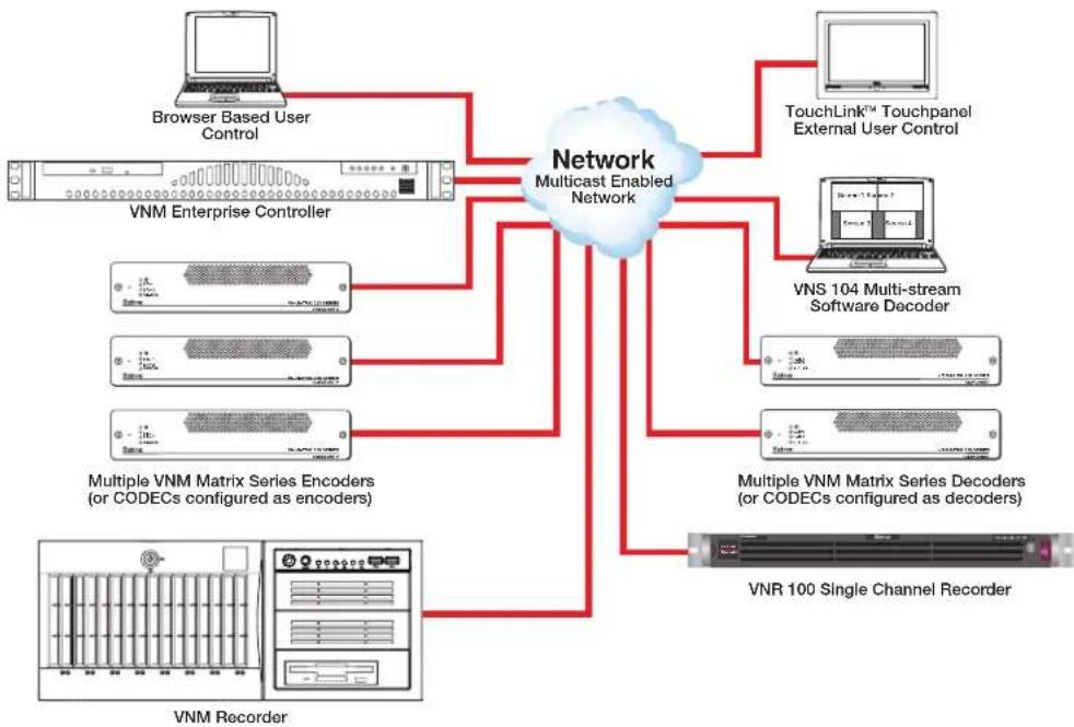
The VNM Enterprise Controller is a dedicated control device for VN-Matrix systems. The Controller simplifies managing a large VN-Matrix deployment allowing users to view, manage, and dynamically control multiple VN-Matrix systems and networked VN-Matrix domains from a single interface. Figure 1 on the next page shows a simple application.
flowchart
graph TD
    A["Browser Based User Control"] --> B["Network Multicast Enabled Network"]
    C["VNM Enterprise Controller"] --> B
    D["TouchLink™ Touchpanel External User Control"] --> B
    E["VNS 104 Multi-stream Software Decoder"] --> B
    F["Multiple VNM Matrix Series Encoders (or CODECs configured as encoders)"] --> B
    G["VNR 100 Single Channel Recorder"] --> B
    H["VNM Recorder"] --> B
    B --> I["Network Multicast Enabled Network"]
    I --> J["Browser Based User Control"]
    I --> K["TouchLink™ Touchpanel External User Control"]
    I --> L["VNS 104 Multi-stream Software Decoder"]
    I --> M["Multiple VNM Matrix Series Encoders (or CODECs configured as encoders)"]
    I --> N["VNR 100 Single Channel Recorder"]
Figure 1. Single VNM Enterprise Controller System with No Redundancy
Two versions of the VNM Enterprise Controller are available:
• VNM Enterprise Controller with fixed hard disk drive
- VNM Enterprise Controller with removable CompactFlash ^® card
NOTE: Both VNM Enterprise Controllers function the same. The only difference is that one has a removable flash card. For additional information on the VNM Enterprise Controller with removable CompactFlash card, see VN-Matrix Product Variants on page 194.
The VNM Enterprise Controller is recommended when:
• More than ten VN-Matrix units are configured into a system.
- A system of VN-Matrix units are interfaced to an external control system requiring dynamic control of the units in a switching solution.
- Preset configurations must be prepared and recalled.
- Redundant system control is required.
For information on setting up a single VNM Enterprise Controller system, see the Single Enterprise Controller Configuration section page 13.
About the Web-based User Interface
Every VN-Matrix system product includes a basic embedded interface for configuration and control of itself and a few additional units. This interface is useful when control is limited to a few units that generally remain in a fixed operational state.
However, for large systems (more than ten devices) the VNM Enterprise Controller provides a more sophisticated user interface that simplifies the configuration and usability of a VN-Matrix system.
About Dual (Redundant) VNM Enterprise Controllers
For applications where it is essential to maintain system control, a second VNM Enterprise Controller can be added with both units configured as part of a redundant pair (see figure 2). In a redundant system, an internal database stores the current system configuration. The internal database is held on both units.
A crossover network cable is fitted to the eth1 port of each VNM Enterprise Controller. This connection is used to monitor the health of the system.
NOTES:
- The crossover connection must use a subnet that is different from the main VN-Matrix network (eth0).
- The crossover cable must be directly connected between the two VNM Enterprise Controller devices without using extra network equipment (such as a switch or router).
When the VN-Matrix system is started, the VNM Enterprise Controllers communicate with each other and one is chosen as the controller for the system. While the VN-Matrix system runs, each VNM Enterprise Controller continually monitors the health of the other. If the primary device (acting as the system controller) fails, the secondary unit takes over control of the VN-Matrix system. Transparent operation and communication within the system is maintained.
The two controllers in a redundant system are known as a "cluster". Each device has its own unique physical IP address (eth0) assigned. A third IP address, known as the cluster address, is also assigned. The cluster IP address is used as the controller IP address for all of the VN-Matrix devices in the system.
For information on setting up a dual (redundant) VNM Enterprise Controller system, see the Dual (Redundant) Controller Configuration section on page 158.

flowchart
graph TD
    A["VNM Enterprise Controller (Primary)"] --> B["ETH1 Cluster Port"]
    A --> C["Eth0 Physical Port (VN-Matrix Network) 192.168.254.254"]
    A --> D["Crossover Cable 192.168.253.0"]
    A --> E["Eth1 Cluster Port"]
    A --> F["VNM Enterprise Controller (Secondary)"]
    F --> G["Cluster Address 192.168.254.250"]
    F --> H["Eth0 Physical Port (VN-Matrix Network) 192.168.254.253"]
    G --> I["Network Multicast Enabled Network"]
    H --> I
    I --> J["TouchLink™ Touchpanel External User Control"]
    I --> K["Multiple VNM Series Devices"]
    I --> L["Browser Based User Control"]
Figure 2. Dual (Redundant) VNM Enterprise Controller System
Transport Protocols Used for Streaming
The source data from a VN-Matrix encoder can be distributed to multiple displays/decoders (one-to-many) or to a single display/decoder (point-to-point). A previously recorded stream can be distributed in the same way and may be thought of as an encoder in this context.
A stream may be transported from the source (encoder, recorded stream) to the display (decoder) using one of three methods:
• Multicast Real-time Transport Protocol (RTP)
• Unicast Real-time Transport Protocol (RTP)
• Unicast Transmission Control Protocol (TCP)
These transport protocols are summarized in this section. For information on how to change the transport protocol used by the VNM Enterprise Controller see System Config Page on page 28.
Multicast RTP – An Overview
Multicast Real-time Transport Protocol (RTP) allows a source to be viewed on multiple displays. This method uses a real-time variation of UDP (User Datagram Protocol).

flowchart
graph LR
    A["SOURCE"] -->|RTP| B["Network"]
    B -->|R| C["DISPLAYS"]
    C -->|RTP| D["Multi decoders can be part of the multicast group."]
    B -->|RTP| E["Display"]
    E --> F["Output"]
    style A fill:#f9f,stroke:#333
    style C fill:#ccf,stroke:#333
    style D fill:#cfc,stroke:#333
    style E fill:#fcc,stroke:#333
Figure 3. Multicast RTP Streaming
The source encoder uses RTP to send data to a multicast group. The source does not need to know the IP address of the decoders that are using the source.
RTP provides very low latency which is important for video streaming. Unlike other protocols, RTP packets include a time stamp. If packets are received in the wrong order, they are sorted into the correct order for display or discarded if the time stamp is out-of-date.
However, because RTP is a connectionless protocol, data delivery is not guaranteed. When data packets are lost (for example, due to excessive network traffic) the VN-Matrix devices carefully manage the data stream to minimize image disruption.
Unicast RTP – An Overview
Similar to multicast RTP, this method uses a real-time variation of UDP, called unicast RTP. Unicast RTP is used where the network infrastructure does not support multicast traffic. Typically, this protocol is used for point-to-point configuration (single source to single display), but can be configured to stream to a maximum of four displays.
NOTE: The encoder sends an individual stream to each decoder. This means that the total bandwidth of the VN-Matrix system increases as more decoders are added.

flowchart
graph LR
    A["SOURCE"] -->|RTP (1 - 4)| B["Network"]
    B -->|RTP 1| C["DISPLAYS"]
    B -->|RTP 2| D["Display"]
    B -->|RTP 3| E["Display"]
    B -->|RTP 4| F["Display"]
    style A fill:#f9f,stroke:#333
    style B fill:#ccf,stroke:#333
    style C fill:#cfc,stroke:#333
    style D fill:#fcc,stroke:#333
    style E fill:#cff,stroke:#333
    style F fill:#ffc,stroke:#333
Figure 4. Unicast RTP Streaming
RTP provides very low latency which is important for video streaming. Unlike other protocols, RTP packets include a time stamp. If packets are received in the wrong order, they are sorted into the correct order for display or discarded if the time stamp is out-of-date.
However, because RTP is a connectionless protocol, data delivery is not guaranteed. When data packets are lost (for example, due to excessive network traffic) the VN-Matrix devices carefully manage the data stream to minimize image disruption.
Unicast TCP – An Overview
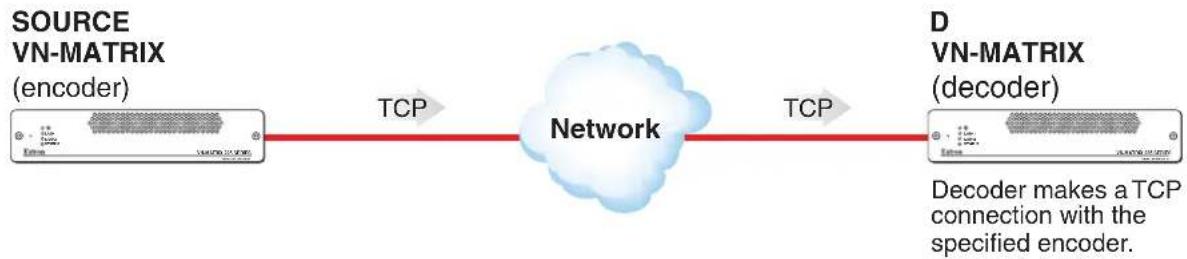
This method transports data using standard Transport Control Protocol (TCP) and should only be used for single point-to-point transfer of data.
TCP is a connection-based protocol and, therefore, data delivery is guaranteed. However, in the event of excessive network traffic, delivery can be delayed, impacting real-time performance.
flowchart
graph LR
    A["SOURCE VN-MATRIX (encoder)"] -->|TCP| B["Network"]
    B -->|TCP| C["D VN-MATRIX (decoder)"]
    C -->|Decoder makes a TCP connection with the specified encoder.| B
Figure 5. Unicast TCP Streaming
The decoder defines which source it connects to. Other than defining an IP address and source type (if required), no special source encoder setup is required.
Definitions
- PURE3 — PURE3 ^ is specifically designed for network transmission of real time media (such as video or graphics, audio, data, and whiteboard elements). It features both spatial and temporal image compression, which allows for efficient bandwidth usage and eliminates the need for forward error correction.
- PURE3 streams always contain video or graphic elements.
-
PURE3 streams may contain audio, data, and whiteboard elements that are associated with the video and graphic elements.
-
Streaming media (stream) — Multimedia that is constantly received by (and normally presented to) an end-user while being delivered by a streaming provider. Internet television is a commonly streamed medium. Streaming media (stream) in this guide refers to a PURE3 media stream that is produced by a VN-Matrix encoding device.
- Element — This term refers to the video/graphics, audio, (user) data, and whiteboard (annotation data) content that is contained within a stream.
- Device license — This term refers to the number of licensed features that are available on a device within a VN-Matrix system. All devices contain a default license that offers a default level of functionality. For information about device licenses, see License Menu on page 57.
- Controller license — This term refers to the license that is applied to the VNM Enterprise Controller (see Controller Firmware and License Updates on page 179 for information about controller licenses).
- (User) Data — This term refers to the transfer of user data between an encoder and a decoder. User data is created at the encoder, placed into the PURE3 stream, and sent to the decoder. The data is received in the same form that it was transmitted. This method of data transfer is unidirectional and can only be sent from an encoder to a decoder.
- Whiteboard (wb) data — Also known as annotation data, whiteboard data outputs text and/or simple pointer annotation onto local displays that are connected to VN-Matrix encoders or decoders. This type of data is bidirectional, which allows a decoder to send whiteboard data to an encoder.
- Cluster — This refers to VNM Enterprise Controllers that are paired in a redundant configuration. A cluster IP address is used to access both VNM Enterprise Controllers at the same time.
- Cluster IP address — This refers to a single IP address that is used to access paired VNM Enterprise Controllers. A unique IP address on the same subnet as assigned to the eth0 port of the primary and secondary VNM Enterprise Controllers is used as the cluster IP address.
NOTE: When configuring the controller IP address of VN-Matrix devices, use the VNM Enterprise Controller cluster IP address.
Features
• Monitor, configure, and manage all VN-Matrix units as a system.
- Supplies the network heartbeat for encoder and decoder synchronization and communication.
- High-level interface provides single point of control for external control systems.
- Manage multiple VN-Matrix systems in combined or independent domains.
- Provides redundant control in mission critical applications.
Panels and Cabling
This section provides information on:
• Installation Overview
- Front Panel Features
• Rear Panel Features
Installation Overview
- Turn off and disconnect the VNM Enterprise Controller and all existing devices.
- Mount the controller (see Mounting on page 206).
- Connect all devices to the controller (see Front Panel Features below and Rear Panel Features on page 9).
- Reconnect and power on all devices.
- Configure the controller.
- Configure all connected devices.
Front Panel Features
NOTE: Some features listed in this user guide may not be available on some units. This will not affect the overall functionality of the VNM Enterprise Controller.
The front panel of the VNM Enterprise Controller is shown in figure 6 below.

Figure 6. VNM Enterprise Controller Front Panel
A CD/DVD drive — Insert any compatible CD or DVD into this drive. This drive is used to update the VNM Enterprise Controller software. The drive is not required for normal operation.
A compact flash drive can replace the CD/DVD drive. For more information on the compact flash drive, see VN-Matrix Product Variants on page 194.
ATTENTION:
B Status LEDs — Five LEDs provide the status of the VNM Enterprise Controller (see figure 6 on the previous page).

Overheat

Network Activity (2)

Network A

ctivity (1)

Power
Figure 7. Status LED Icons
- Overheat LED — When this LED is lit, the controller has achieved a condition which can cause it to overheat. The LED remains on for as long as the condition exists.
NOTE: If this LED is continuously lit, it can be caused by cables obstructing the airflow of the controller or the ambient room temperature. Check the routing of the cables and make sure all fans are operating normally. If necessary, move the controller to a cooler location or adjust the room temperature.
• Network Activity LED (2) — This LED flashes to indicate activity on the second network.
• Network Activity LED (1) — This LED flashes to indicate activity on the first network.
- Drive Activity LED — This LED flashes to indicate hard drive and CD/DVD drive activity.
• Power LED — This LED lights when the controller is receiving power.
C Reset button — This button reboots the system.
Power button — This is the main power button, used to apply or turn off the main power. When the main power is turned off, standby power is actively supplied to the controller.
E USB (Universal Serial Bus) ports — Insert any compatible USB device into these ports. The ports are not required for normal operation.
Rear Panel Features
NOTES:
- Some features listed in this user guide are not available on each unit. This does not affect the overall functionality of the VNM Enterprise Controller.
- Items A, G, and H are required for normal operation. The other items are used when upgrading the VNM Enterprise Controller.
The rear panel of the VNM Enterprise Controller is shown in figure 8 below.

Figure 8. VNM Enterprise Controller Rear Panel
Power input (IEC connector) — Plug a standard IEC power cord into this connector to connect the controller to a 100 to 240 VAC, 50 Hz or 60 Hz power source.
B PS/2 mouse connector (optional) — Connect a PS/2 mouse to this port.
PS/2 keyboard connector (optional) — Connect a PS/2 keyboard to this port.
USB (Universal Serial Bus) connectors — Insert any compatible USB device into these ports.
E COM1 serial connector (optional) — Connect a compatible device to this 9-pin serial port. This port can control the VNM Enterprise Controller using HLI commands (see System Control on page 175).
F VGA connector (optional) — Connect a compatible VGA monitor to this port.
G Ethernet connector (eth0) — Connect an RJ-45 cable to this port. This port connects to a primary network and is the default network port to connect the controller to a VN-Matrix network.
H Ethernet connector (eth1) — Connect an RJ-45 cable to this port. This port connects to a second VNM Enterprise Controller and is used to monitor the status of the primary VNM Enterprise Controller in a redundant configuration. This port is also referred to as the "cluster" or "service" port.
Controller Configuration and Operation
This section provides information on:
• Power Up Procedure
• Web-based User Interface Overview
- Accessing the Web-based User Interface
• Power Down Procedure
Power Up Procedure
NOTE: Before turning on the VNM Enterprise Controller, ensure that all necessary devices are powered on and connected properly.
- Plug the IEC power cord into the VNM Enterprise Controller (see Rear Panel Features, A on page 9).
- Press the power button on the front of the unit (see Front Panel Features, D on page 7). The power LED lights indicating the unit is powered. The VNM Enterprise Controller takes about 60 seconds to boot before it is fully operational.
Web-based User Interface Overview
The web-based user interface is used to configure the controller and operate connected devices in a VN-Matrix network. It is accessed by entering the IP address of the VNM Enterprise Controller into a compatible web browser (see Browser Configuration on page 200). The user interface provides system level configuration, monitoring, and operation of VN-Matrix devices connected to the VNM Enterprise Controller. The following list outlines the main features of the user interface.
- Codec device configuration includes device name, compression settings, peripheral communications, and device mode.
- Monitor the network bit rate and active connections in a VN-Matrix system.
- Enable and configure the on-screen display (OSD) feature for VN-Matrix devices.
- Update the firmware of connected VN-Matrix devices.
- Record and play back video using a connected VN-Matrix recorder.
- Create and save presets to quickly reconfigure devices.
- Stream to desktops with VN-Matrix software decoders.
Accessing the Web-based User Interface
To access the web-based user interface:
-
Configure the network settings of a control PC so that it is compatible with the VN-Matrix network and connect the control PC to the VN-Matrix network.
-
Open a compatible web browser (Microsoft ^® Internet Explorer ^® version 7 or above or Mozilla ^® Firefox ^® version 1.3 or above) running on the PC or laptop connected in step 1.
NOTE: See Configuring the Network Settings on page 14 for information on how to configure the network settings of the VNM Enterprise Controller.
- In the address bar, enter the IP address of the Enterprise Controller (default IP address is 192.168.254.254).
The login screen opens in the browser (see figure 9). The controller is security protected.
NOTE: If the web browser cannot access the web-based user interface, the security settings of the web browser may need to be configured (see Browser Configuration on page 200 for more information).
Extron Electronics Matrix Enterprise Controller

Figure 9. VNM Enterprise Controller Login Page
- Enter the appropriate username and password. Two profiles are available.
NOTES:
- The procedures detailed use the administrator username and password to configure the VNM Enterprise Controller. Extron recommends that the administrator username and password be given only to those who require it. Others should use the guest login information to access the controller ensuring that important configuration settings are not changed.
- Username and password entries are case sensitive.
- For information on how to change the password, see Changing the login password on page 21.
- Guest — This profile hides the Configuration and Format Editor tabs prohibiting system changes to the Enterprise controller.
- Guest username — Default: user
• Guest password — By default, no password is required.
- Administrator — This profile allows full access to all of the web-based user interface configuration settings and is the default configuration profile.
• Administrator username — Default: admin
- Administrator password — By default, no password is required.
- Click Login or press
. The Devices page opens (see figure 10) and the VNM Enterprise Controller is now ready for configuration and operation.
NOTE: The Devices page only displays devices properly configured to operate with the VNM Enterprise Controller (see the user guides for individual devices for more information). The VNM Enterprise Controller must also be configured properly.
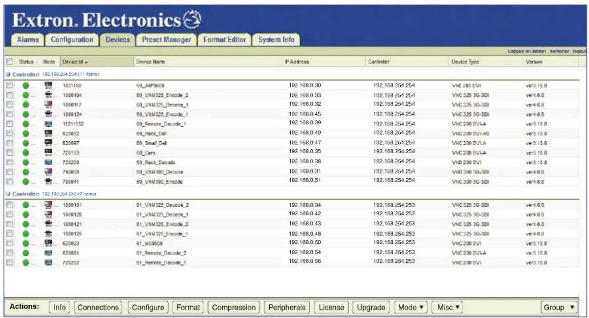
Figure 10. Devices Page
The Alarms, Configuration, and System Info pages, are used to configure and operate the Enterprise Controller. The remaining tabs for the Devices, Preset Manager, and Format Editor pages can configure and operate connected devices.
Power Down Procedure
To power down the VNM Enterprise Controller, press the power button on the front of the controller (see Front Panel Features, D on page 7). The power LED turns off.
NOTE: Turning off the controller using the power button removes the main power, but standby power is still supplied to the system.
Single Enterprise Controller Configuration
This section details basic information needed to configure the settings of a single VNM Enterprise Controller. For information on how to set up redundant VNM Enterprise Controllers, see Dual (Redundant) Controller Configuration on page 158.
This section provides information on:
- Setup Overview
- Single VNM Enterprise Controller Configuration
- Configuring a Single Enterprise Controller as the System Controller
- Configuring the VN-Matrix Devices
NOTE: For additional configuration information, see Advanced Controller Configuration on page 19.
Setup Overview
- Use a network switch to connect the primary VN-Matrix network to the rear panel Ethernet connector (eth0) of the VNM Enterprise Controller (see Rear Panel Features on page 9).
- Power on the VNM Enterprise Controller, all VN-Matrix devices present in the system, and all necessary devices (see Power Up Procedure on page 10).
- Connect a control PC to the VN-Matrix network and navigate to the web-based user interface of the VNM Enterprise Controller (see Accessing the Web-based User Interface on page 11).
- Configure the settings of the VNM Enterprise Controller (see Single VNM Enterprise Controller Configuration on page 14).
- Configure the VNM Enterprise Controller as the VN-Matrix system controller (see Configuring a Single Enterprise Controller as the System Controller on page 17).
- Configure the VN-Matrix system devices (see Configuring the VN-Matrix Devices on page 18).
- If necessary, update the license of the VNM Enterprise Controller (see Controller Firmware and License Updates on page 179).
- Power down the VNM Enterprise Controller (see Power Down Procedure on page 12) and all configured devices. After a few seconds, power on the VNM Enterprise Controller and all necessary devices.
Single VNM Enterprise Controller Configuration
This section details procedures on how to set up and configure a single
VNM Enterprise Controller (see Advanced Controller Configuration on page 19 for additional configuration information).
Configuring the Network Settings
The VNM Enterprise Controller is pre-configured with the following network settings.
IP address: 192.168.254.254
Subnet mask: 255.255.255.0
Gateway: 192.168.254.1
MTU: 1500
NOTE: With these settings, the units connected to the VN-Matrix network must use IP addresses within the range of 192.168.254.2 through 192.168.254.253 and use the same subnet mask.
Use the following procedure to change the network settings of the VNM Enterprise Controller, if necessary.
-
Log on the VNM Enterprise Controller (see Accessing the Web-based User Interface on page 11).
-
Click the Configuration tab (see figure 11, ①).
The Configuration page opens.

Figure 11. Configuration Page — Configuring the Network Settings
- Under Device Properties, click the Network link (2).
NOTE: Make sure the VNM Enterprise Controller is not "paired". If it is paired, the unit must first be unpaired (see Unpairing controllers on page 174). Be aware that unpairing and then pairing a VNM Enterprise Controller deletes device files and custom input or output modes.
- Change the IP Address, Netmask, Gateway, and MTU fields as necessary (see figure 11, ③ on the previous page).
NOTE: The default value of 1500 in the MTU field is the correct setting in most instances.
-
Click Apply Changes ( 4 ), to save and apply the configuration.
-
Configure the IP address of the control PC so that it is within the address range of the VNM Enterprise Controller.
NOTE: Complete this step only if the IP address of the VNM Enterprise Controller is using a network prefix other than 192.168.254.xxx or subnet mask other than 255.255.255.0.
- If necessary, restart the control PC to save the configuration.
Setting the Role
Use the following procedure to set the role of the VNM Enterprise Controller (see Accessing the Web-based User Interface on page 11 for login information).
- Click the Configuration tab. The Configuration page opens (see figure 12, ①).
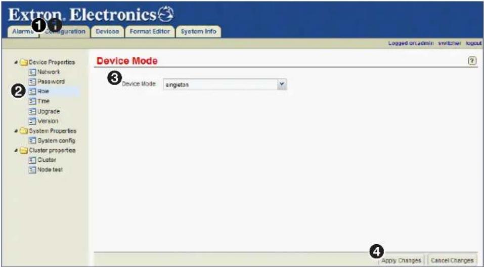
Figure 12. Configuration Page — Single VNM Enterprise Controller Role Setting
-
Click the Role link (②).
-
From the Device Mode drop-down list, select singleton (3).
NOTE: For information on the other device modes, see Role Page on page 22.
- Click Apply Changes (④).
NOTE: The web-based user interface returns to the login page after saving the configuration.
Configuring the Transport Protocol
Use the following procedure to configure the transport protocol that will be used throughout the VN-Matrix system (see Accessing the Web-based User Interface on page 11 for information on how to login).
- Click the Configuration tab.
The Configuration page opens (see figure 13, ①).

Figure 13. Configuration Page — Configuring the Transport Protocol
- Click the System config link (②).
- From the Protocol drop-down list, select the preferred transport protocol that will be used throughout the VN-Matrix system (③).
NOTE: The default transport protocol is Unicast. For more information on transport protocols, see Transport Protocols Used for Streaming on page 4.
- Click Apply Changes (④), to save the configuration.
Configuring a Single Enterprise Controller as the System Controller
This section details how to assign a single VNM Enterprise Controller as the system controller. Before proceeding, make sure the procedures detailed in Single VNM Enterprise Controller Configuration on page 14 are completed first.
NOTE: For information on how to configure dual VNM Enterprise Controllers as system controllers, see Configuring Dual Enterprise Controllers as the System Controller on page 165.
Adding the VNM Enterprise Controller to the Controller List
Use the following procedure to add the VNM Enterprise Controller to the controller list (see Accessing the Web-based User Interface on page 11 for information on how to login).
- Click the Configuration tab.
The Configuration page opens (see figure 14, ①).

Figure 14. Configuration Page — Adding Controllers to the Controller List
- Click the System config link (②).
- Click Add (③). The Peer Controller Address (Add IP) dialog box opens.
- Enter the IP address of this VNM Enterprise Controller and click OK (4).
NOTE: If necessary, clear the Controllers field by highlighting the displayed IP addresses and clicking Delete.
- Click Apply Changes (⑤) to save the configuration.
The VNM Enterprise Controller restarts the user interface, and is assigned as the system controller.
Configuring the VN-Matrix Devices
For the VNM Enterprise Controller to function properly with connected devices:
- Update each VN-Matrix device with the IP address of the VNM Enterprise Controller and configure each device to operate on the same network as the VNM Enterprise Controller.
- Access the VNM Enterprise Controller web-based user interface by entering the IP address of the VNM Enterprise Controller into the address bar of a web browser.
- Use the web-based user interface to select one or more devices from the Devices page and use the Actions menu bar at the bottom of the page to configure the selected devices (see About the Actions Menu Bar on page 40, and Mode Menu (VNC Devices Only) on page 60).
For information on configuring VN-Matrix devices, see the user guide for each device.
Advanced Controller Configuration
The Configuration page contains nine additional pages to configure the general settings of the VNM Enterprise Controller. This section presents a detailed overview of each page. The following configuration pages are available.
• Network Page
- Password Page
- Role Page
• Time Page
- Upgrade Page
- Version Page
- System Config Page
• About the System Info Page
- About the Default Multicast Address
NOTE: The Cluster Page on page 172 and Node Test Page on page 169 appear only when paired VNM Enterprise Controllers are available.
Network Page
The Network page (see figure 15, ①) configures the primary physical (eth0) IP address of the VNM Enterprise Controller.

Figure 15. Network Page
The following fields are available for configuration.
• IP Address — Enter a valid IP address into this field (2).
- Netmask — Enter a valid subnet mask into this field (3).
• Gateway — Enter a valid gateway address into this field (4).
NOTE: The gateway address field is only required if devices are on different subnets.
• MTU — Enter a valid MTU into this field (5).
NOTE: The default value of 1500 in the MTU field is the correct setting for most systems.
- eth0 MAC address — This field details the Media Access Control (MAC) address assigned to the primary physical (eth0) IP address (6). This field cannot be modified.
- eth1 MAC address — This field details the MAC address assigned to the secondary (eth1) IP address (⑦). This field cannot be modified.
For information on how to change the network settings of the VNM Enterprise Controller see Configuring the Network Settings on page 14.
Password Page
The Password page (see figure 16, ①) is used to set the passwords for the administrator and user profiles.

Figure 16. Password Page
Changing the login password
- From the User drop-down list (②), select one of the following account names.

- Select user to change the user password.
- Select admin to change the administrator password.
NOTE: The user name entries (user and admin) cannot be changed.
- Enter the desired password in the top Password field (③). The password can consist of letters, numbers, and the underscore character. Password entries are case sensitive.

- Re-enter the password in the bottom Password field (③).
- Click Apply Changes (④), to save the password.
Role Page
The Role page is used to set the mode of the VNM Enterprise Controller.

Figure 17. Role Page
The following device modes are available.
- singleton — Select this option when a single VNM Enterprise Controller is the system controller.
- redundant_primary — Select this option when a VNM Enterprise Controller is running as the first (primary) unit of a redundant pair.
- redundant_secondary — Select this option when a VNM Enterprise Controller is running as the second (secondary) unit of a redundant pair.
NOTE: If the Device Mode field is set to redundant_primary or redundant_secondary, the cluster properties pages are available for configuration (see About the Cluster Properties Pages on page 172).
For information on setting the different device modes, see:
- Setting the Role on page 15
• Setting the Role of the Primary Enterprise Controller on page 161 - Setting the Role of the Secondary Enterprise Controller on page 162
Time Page
The Time page (see figure 18, ①) is used to manage the clock-related functions available on the VNM Enterprise Controller.

Figure 18. Time Page
Reported Time Panel
This panel (2) contains a read-only field that displays the current system time of the controller that is logged in to.
NOTE: When logged into a cluster, the time of the primary controller is displayed in this field.
Clock Synchronization Panel
This panel (see figure 18, ③ on the previous page) is used to determine the primary clock source for the controller.
NOTE: If there is only one VNM Enterprise Controller in the system, it is not necessary to configure clock synchronization.
All devices in a VN-Matrix system (controllers, encoders, decoders, and recorders) reference a primary system clock, sourced from the controller.
If the Enable Clock Synchronization check box is selected, the controller that is logged in offsets its own time to match the system time of the first VNM Enterprise Controller in the Sources list. If the first controller fails, the system time of the second controller in the list is used as the reference, and so on.
If the Enable Clock Synchronization check box is not selected, the controller that is logged in references its own clock for the system time (in the case of a singleton system with one VNM Enterprise Controller) or the time of the controller acting as the primary (in the case of a paired VNM Enterprise Controller cluster).
NOTES:
- Only physical IP addresses of VNM Enterprise Controllers should be added to the Sources list. Do not use service (cluster) IP addresses.
- The order of the controllers in the Sources list should be identical for each VNM Enterprise Controller.
Adding controllers to the Sources list
NOTE: Only IP addresses of valid controller devices can be added to this list.
- To add a controller to the list, click the Add button located below the Sources list.
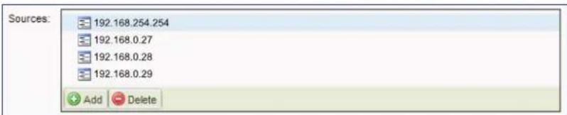
- The following dialog box appears.

- Enter the desired IP address and click OK.
- Repeat steps 1 through 3 for each controller in the VN-Matrix system.
- When finished adding controllers, click Apply Changes located at the lower right corner of the web page.
Removing controllers from the Sources list
- To remove a controller from the list, select a controller from the Sources list.
- Click the Delete button located below the Sources list to remove the selected IP address.
- When finished, click Apply Changes located at the lower right corner of the web page.
Enabling clock synchronization
- Add all of the controller IP addresses to the Sources list (see Adding controllers to the Sources list on page 24). Do not add service (cluster) IP addresses.
- Select the Enable Clock Synchronization check box.
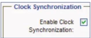
- Click Apply Changes, located at the lower right corner of the web page, to save the setting.
- Repeat this procedure for each controller device listed in the Sources list.
Disabling clock synchronization
- Deselect the Enable Clock Synchronization check box.
- Click Apply Changes, located at the lower right corner of the web page, to save the setting.
Clock Settings Panel
This panel (see figure 18, 4 on page 23) is used to set the local time and date on the controller that is logged into.
NOTES:
- Do not alter these fields if logged into the cluster IP address.
- If Enable Clock Synchronization is selected in the Clock Synchronization panel (3), the values in this panel are dimmed.
- Set time — Enter the local time into this field or use the drop-down list button located at the right side of this field to select the desired time.
The time is entered as follows.
- Use the HH:MM:SS (hours:minutes:seconds) format based on the 24-hour clock. For example, 08:25:00 for AM or 20:35:10 for PM.
- Set date — Enter the current date into this field or use the calendar button located at the right side of this field to open a calendar and select the desired date.
The date is entered as follows.
• Use the MM/DD/YYYY (month/day/year) format. For example, 05/14/2012.
Setting the time and date
NOTES:
- Set the time zone before manually setting the time and date (see Setting the time zone, below).
- Do not alter these fields if logged into the cluster IP address.
1. Make sure Enable Clock Synchronization is not selected.

NOTE: If Enable Clock Synchronization is checked, the Set time and Set date fields are dimmed.
2. Enter the time in the Set time field.
Set time: 11:39:43
- Use the HH:MM:SS (hours:minutes:seconds) format based on the 24-hour clock. For example, 08:25:00 or 20:35:10.
3. Enter or select the date in the Set date field.
Set date: 11/05/2010
• Use the MM/DD/YYYY (month/day/year) format. For example, 05/14/2016.
4. Cick Apply Changes, located at the lower right corner of the web page, to save the configuration.
Time Zone Panel
This panel (see figure 18, ⑤ on page 23) is used to set the time zone.
- Set timezone — Use the drop-down list located at the right side of this field to select the desired time zone.
NOTE: Setting the time zone automatically adjusts the field in the Reported Time Panel (see Reported Time Panel on page 23).
Setting the time zone
- Select the desired time zone from the Set timezone drop-down list.
Set timezone: EST5EDT
- Click Apply Changes, located at the lower right corner of the web page, to save the configuration.
Upgrade Page
The Upgrade page is used to update the firmware of the VNM Enterprise Controller.
- For information on updating the firmware of a single VNM Enterprise Controller, see Updating the Firmware of a Single Enterprise Controller on page 181.
- For information on updating the firmware of dual (redundant) VNM Enterprise Controllers, see Updating the Firmware of Dual (Redundant) Enterprise Controllers on page 181.
Version Page
The Version page (see figure 19, ①) details the versions of firmware running on various components of the VN-Matrix system.
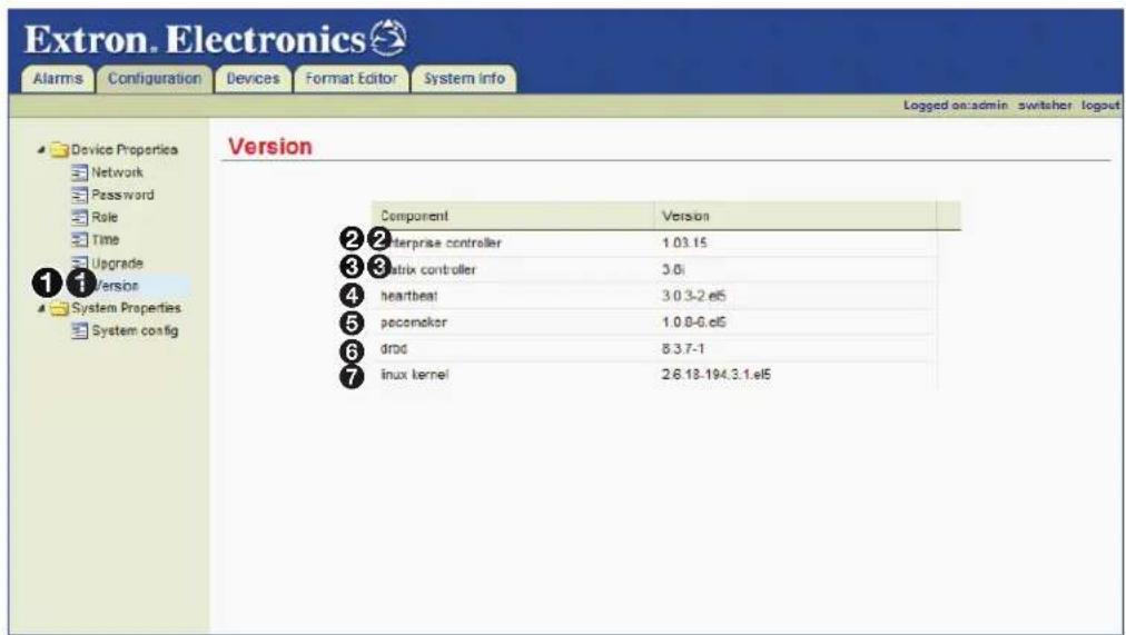
Figure 19. Version Page
The following fields are read-only (cannot be edited).
- enterprise controller — This field ( ②) displays the version of software that is running on the VNM Enterprise Controller.
- matrix controller — This field ( 3) displays the version of firmware that is running on the VNM Enterprise Controller.
- heartbeat — This field ( 4) displays the Heartbeat clustering software version that is running on the VNM Enterprise Controller. The Heartbeat and Pacemaker software work together to create a cluster.
- pacemaker — This field (5) displays the Pacemaker clustering software version that is running on the VNM Enterprise Controller. The Heartbeat and Pacemaker software work together to create a cluster.
- drbd — This field (6) displays the Distributed Redundant Block Device (DRBD®) version that is running on the VNM Enterprise Controller. DRBD is used to manage and sync a cluster of VNM Enterprise Controllers.
- linux kernel — This field (⑦) displays the version of Linux that is running on the VNM Enterprise Controller.
System Config Page
The System Config page (see figure 20, ①) is used to configure the following sets of control options.
- Transport protocol (multicast RTP, unicast TCP, unicast RTP)
• Multicast addressing schemes - Clean switch
- Controller listing
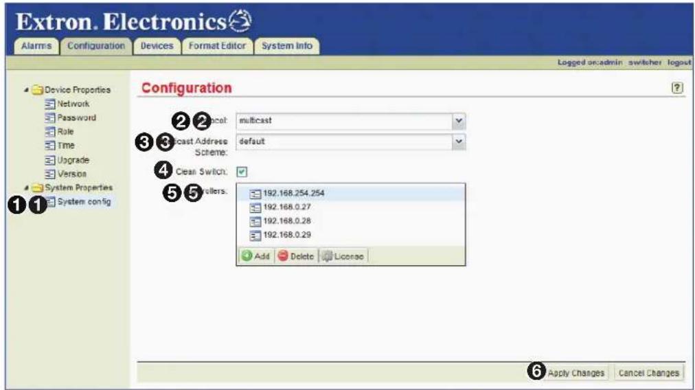
Figure 20. System Config Page
The following options are available for configuration.
- Protocol — This drop-down list (②) sets the default transport protocol. Three transport protocol selections are available.
- multicast — This transport protocol supports unlimited endpoints (displays) per single stream (source) (see Multicast RTP — An Overview on page 4).
- unicast — This transport protocol supports up to four endpoints (displays) per single stream (source) (see Unicast RTP — An Overview on page 5).
- tcp — This transport protocol supports one endpoint (display) per single stream (source) (see Unicast TCP — An Overview on page 5).
- Multicast Address Scheme — This drop-down list (see figure 20, ③ on the previous page) selects the algorithm that calculates the multicast addresses within the VN-Matrix system.
NOTES:
- This option needs to be set only if multicast is selected in the Protocol field.
- Class C (255.255.255.0) subnet addresses are supported by default. Contact the Extron S3 Sales and Technical Support Hotline regarding other addressing schemes.
Three multicast address schemes are available.
- default — This setting assumes that VN-Matrix devices on the system use Class C (255.255.255.0) subnet addresses. This is the default setting (see About the Default Multicast Address on page 31).
- octet-0-1-3 — This is specific to systems that have special addressing schemes. This scheme is not suitable for use on standard system configurations and should not be used.
- octet-1-3 — This scheme is specific to systems that have special addressing schemes. This scheme is not suitable for use on standard system configurations and should not be used.
Select the default multicast address scheme and click Apply Changes (6), located at the lower right corner of the web page, to save the setting.
- Clean Switch (VN-Matrix 2xx only) — The clean switch (4) feature allows glitch free transitions when switching between decoded streams. Select the check box to activate the clean switch option or deselect to deactivate the clean switch option. Click Apply Changes (6), located at the lower right corner of the web page, to save the setting.
NOTES:
- The scale output feature must be activated on the decoder when using clean switch.
- VN-Matrix 300 / 325 devices do not support Clean Switch and ignore this setting.
- Controllers — This field (5) is used to add the IP addresses of all singleton and service (cluster) controllers. This field is used to keep the VNM Enterprise Controller that is logged into aware of the devices it is controlling and the devices that are managed by the other controllers in the system. This field allows streaming between devices managed by other controllers, as well as editing configuration options of devices connected to other controllers.
NOTE: If only one controller is used in the VN-Matrix system, the IP address of the controller still needs to be added to this field. If the IP address is not added, the Devices page is empty (see About the Actions Menu Bar on page 40).
Adding and removing controllers from this field is similar to adding and removing controllers on the Time page (see page 23).
For information on how to add and remove controllers:
- Adding controllers to the Sources list on page 24
- Removing controllers from the Sources list on page 25
About the System Info Page
This page is accessed by selecting the System Info tab (see figure 21).

Figure 21. System Info Page
The System Info page displays general information about the VNM Enterprise Controller. If the VN-Matrix system contains multiple controllers, they are displayed on this page by IP address using individual columns. The following information is displayed.
① cluster_server — This field displays the role of the VNM Enterprise Controller cluster as follows:
- singleton for a single Controller that is NOT running as part of a redundant cluster.
- primary for a Controller running as part of a cluster, with the unit configured as the redundant_primary unit in control of the cluster.
• secondary for a Controller running as part of a cluster, with the unit configured as the redundant_secondary unit in control of the cluster.
② hli.memory_usage — This field displays the amount of memory the VNM Enterprise Controller cluster is currently using for the web-based user interface.
③ hli.uptime — This field displays the number of days the VNM Enterprise Controller cluster web-based user interface has been operational.
4 server.disk_usage — This field displays the amount of disk space being used by the VNM Enterprise Controller cluster to keep the VN-Matrix system operational.
⑤ server.memory_usage — This field displays the amount of memory being used by the VNM Enterprise Controller cluster to keep the VN-Matrix system operational.
⑥ server.uptime — This field displays the number of days the VNM Enterprise Controller cluster server has been operational.
⑦ time.delta — This field displays the time difference between the clock of this Controller and the reference time source. This value is normally less than one video frame.
⑧ time.last_mark — This field displays the date and time that the cluster was last updated.
⑨ time.last_rejam — This field displays the date and time that the cluster was force updated.
10 time.last_switch — This field displays the date and time that the cluster last switched roles (primary to secondary or secondary to primary).
⑪ time.source — This field displays the device being used for clock synchronization within the VN-Matrix system.
About the Default Multicast Address
When multicast is chosen as the transport protocol, the VNM Enterprise Controller assigns multicast IP addresses automatically. Three schemes are available. Each of these schemes is designed to calculate and assign a multicast address based on the IP address of an encoder device. This section details how the default multicast address scheme operates.
The default multicast address scheme is used for all VN-Matrix systems. It creates at least one and a maximum of four multicast addresses for each encoder. This is dependant on how many stream elements are selected for transport. The table below details how the IP address is derived.
| Default Multicast Address Scheme | ||
| Address Type Address Format Description and Comments | ||
| VN-Matrix deviceIP address | aaa.bbb.ccc.ddd | aaa.bbb.ccc. is the subnet. |
| ddd is a host number in the range 1 to 254. | ||
| VN-Matrix devicesubnet mask | 255.255.255.0 | Subnet mask set on all devices. |
| Derived multicastaddress | 239.192.bbbxxxyy.zzzzzzzz | b represents bits 8, 7, and 6.- These bits are always 0. |
| x represents bits 5, 4, and 3 and is the channel number in the range 0 to 4.- Encoders are always 0.- Recorder channels are 0 to 4 as appropriate. | ||
| y represents bits 2 and 1 and is the stream element number.- 00 = audio- 01 = video- 10 = whiteboard- 11 = data | ||
| z represents the value of the fourth octet in the host IP address. | ||
An example of how video multicast addresses are created is shown in the table below.
| Video Multicast Address Example for IP Address 192.168.0.102 | |||
| Item Value Binary Comments | |||
| Default Value for the First Two Octets | |||
| First octet | 239 | All multicast addresses in this scheme use these values. | |
| Second octet | 192 | ||
| Deriving the Third Octet This is a binary value | derived as follows. | ||
| Bits 8, 7, 6 (bbb) | ∅ | 000 xxx yy The most significant three bits are always ∅. | |
| Channel number (xxx) | ∅ | bbb 000 yy The channel number for an encoder is ∅. | |
| Video stream element (yy) | 1 | bbb xxx ∅1 | The value for the video stream element is ∅1. |
| Resulting third octet | 1 | 000 000 ∅1 | |
| Deriving the Fourth Octet | |||
| Fourth octet (z) | 102 | Takes the value of the last octet in the device IP address. | |
| Final Multicast Address | |||
| Video stream multicast address | 239.192.1.102 | ||
For each of the multicast group addresses, the VNM Enterprise Controller creates two port numbers. The table below details how port numbers are derived.
| Default Multicast Address Port Numbers | ||
| Port Type Port Format Description and Comments | ||
| Base port number | 9004 | |
| Derived port number (even) | 9004 + xxxyyzzzzzzzzE | x represents the channel number in the range 0 to 4.- Encoders are always 0.- Recorder channels are 0 to 4 as appropriate. |
| y represents the stream element number.- 00 = audio- 01 = video- 10 = whiteboard- 11 = data | ||
| z represents the value of the last octet in the host IP address. | ||
| E represents the last bit.- 0 makes the port number an even value.- 0 + 1 makes the port number an odd value. | ||
| Derived port number (odd) | 9004 + xxxyyzzzzzzzz0 + 1 | Derived even port number plus 1. |
An example of how port numbers are created is shown in the table below.
| Video Port Number Example for IP Address 192.168.0.102 | |||
| Item Value Binary Comments | |||
| Base port number | 9004 | All multicast port numbers in this scheme start from this value. | |
| Deriving the Port Number Offset | |||
| Channel number (xxx) | 0 000yyzzzzzzzzE | The channel number for an encoder is 0. | |
| Video stream element (yy) | 1 xxx01zzzzzzzzE | The value for a video stream element is 01. | |
| Fourth octet (zzzzzzzzz) | 102 xxxyy01100110E | Takes the value of the last octet in the device IP address. | |
| Last bit (E) | 0 xxxyyzzzzzzzzz0 | Always 0 to make the port number an even value. | |
| Port number offset value | 716 00001011001100 | 716 is the decimal value of the binary number. | |
| Creating the Final Port NumberNOTE: There are two port numbers associated with each multicast address.The even port number is for RTP stream data. The odd port number is for the associated RTCP data. | |||
| Final port number (RTP, video) | 9720 | The sum of 9004 and the port offset value, 716. | |
| Second port number (RTCP, video) | 9721 | Even port number plus 1. | |
VN-Matrix Device Configuration and Control
The VN-Matrix Enterprise Controller is the center of an audio and video streaming network that connects and controls VN-Matrix hardware encoders, decoders, recorders, and software decoders.
The controller can control all VN-Matrix devices residing on the same network. Each matrix device must have its system controller IP address set to the IP address of the controller.
The matrix devices are monitored and configured from the device list page. The Preset Manager page builds connections between VN-Matrix devices. The presets are saved for later use to enable rapid system configuration.
This section provides instructions on how to view VN-Matrix codecs, recorders, and software decoders on a VNM Enterprise Controller, configure the devices for proper operation, and to operate those devices in a VN-Matrix network.
Sections include:
• Devices Page Overview
• About the Devices Page
• About the Actions Menu Bar
- Actions Menu Bar Overview
• Device Configuration
• VNM 200/225/300/325 Configuration
• VNM 250 Configuration
- Recorder Configuration
• VNS 104 Software Decoder Configuration
• About the Switcher Page
For the VNM Enterprise Controller to operate and control devices on the network:
- Update each VN-Matrix device with the IP address of the VNM Enterprise Controller and configure them to operate on the same network as the VNM Enterprise Controller.
- Access the VNM Enterprise Controller web-based user interface from a control computer on the same network by entering the IP address of the VNM Enterprise Controller into the address bar of a web browser (see Accessing the Web-based User Interface on page 11).
- Use the web-based user interface to select one or more devices from the Devices page and use the Actions menu bar at the bottom of the page to configure the selected device (see About the Devices Page on the next page).
For information on the configuration of VN-Matrix devices, see the user guide for each device.
Devices Page Overview
The VN-Matrix Enterprise Controller is the center of an audio and video streaming network that connects and controls VN-Matrix hardware encoders, decoders, recorders, and software decoders. The controller provides support for third party system control using the HLI protocol.
The following VN-Matrix devices are discussed in this section:
| Device Description | |
| VNM 2xx Series DVI, HDMI, and RGB encoders, decoders and codecs | |
| VNM 3xx Series 3G-SDI codecs | |
| VNR 100 Single channel recorder/player | |
| VNM Recorder Five-channel recorder/player | |
| VNS 104 Multi-stream software decoder | |
To use the devices in a VN-Matrix system, the Enterprise Controller is required. The devices are added to the system, then configured for control from the EC. The controller connects the devices together in smaller systems to support specific operations and tasks using the Preset Manager (see Preset Manager on page 92).
About the Devices Page
The Devices page lists all VN-Matrix devices detected on the network and is the main page for configuring and managing devices. This is also the default page opened after logging in (see figure 22).
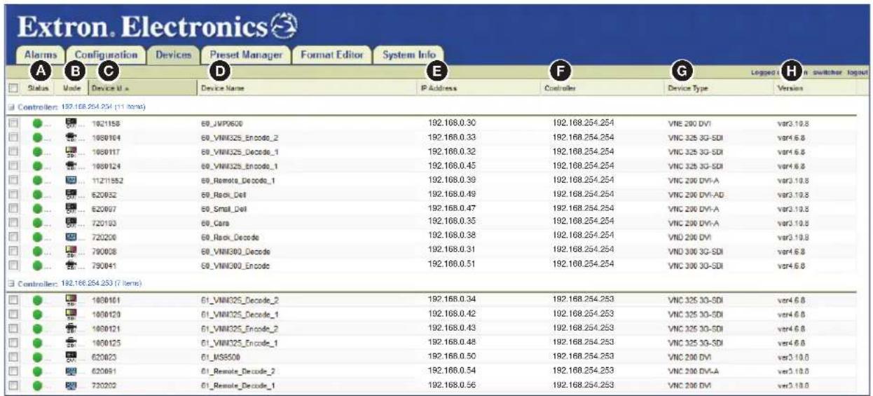
Figure 22. Devices Page
NOTE: If devices are added after the page has opened, they might not automatically appear in this list. Refresh the page or click the Devices tab to update the list.
When a VN-Matrix device is detected and listed on the Devices page, an entry is always displayed even if the device is subsequently disconnected. All valid devices are listed by device name and followed by their current IP address.
NOTE: Some listed devices will not show an IP address. These devices are inactive. A device is considered inactive if it is disconnected from the network or powered down.
The columns on the devices page detail important information about VN-Matrix devices. Each recognized device is listed.
A Status Icons — The status of a device is indicated by a colored icon.

A device under active control and connected to the VN-Matrix network.

A device that is not under active control (not online in the VN-Matrix network).
B Mode Icons — The current configuration status of each device is identified by an icon.

An undefined device. This icon is shown when a codec device is connected to the VN-Matrix system for the first time and before it has been configured as a source or a display.

A VN-Matrix 200 / 225 device configured as an encoder (source).

A VN-Matrix 200 / 225 device configured as a decoder (display).

A VN-Matrix 300 / 325 device configured as an encoder (source).

A VN-Matrix 300 / 325 device configured as a decoder (display).

A VNE 250 encoder.

A VND 250 decoder.

A VNR 100 recorder.

A VN-Matrix 5-channel recorder.

A single sub-channel of a VN-Matrix 5-channel recorder.

A VNS 104 software decoder.

A single VNS 104 window. The lit window indicates the position of the window with active streaming (example icon indicates window 1).

NOTE: A warning triangle over the device icon represents an issue or a problem with the device (such as the device not having an active source or display connection). Search for the device on the Alarms Page (see page 153) to see if the device contains an active alarm.
Device ID — The devices unique identifier is shown in this column.
Device Name — The device name is shown in this field. To change the name of the device, see Device Name in the Configure Menu on page 44.
E IP Address — The IP address of the device is shown in this column.
NOTE: The IP address of a device is shown only if the device is currently present on the network and configured to use the VNM Enterprise Controller.
F Controller — This column shows the IP address of the device acting as the system controller.
G Device Type — This column shows the type of device connected to the VN-Matrix system.
Version — This column shows the current firmware version installed on each device.
NOTE: To avoid compatibility issues, all devices of the same model must have the same version of firmware installed on each device.
Sorting Devices by Column
Columns can be sorted by clicking directly on any of the column names. Click a column name to sort the list in ascending or descending order. Figure 23 shows the devices sorted by device ID number. The Device Id column (1) is darkened and contains an ▲ icon to indicate the devices are sorted by the Device ID number in ascending order.

Figure 23. Sort by Device ID
Hovering over the right side of a column name reveals a drop-down arrow that, when clicked, accesses the advanced column sorting menu (see figure 24). Use this menu to sort columns in ascending or descending order and populate the page with necessary information by adding or removing columns. A checkmark indicates the column is visible.

Figure 24. Advanced Column Sorting
Sorting Devices by Group
Devices can be sorted in groups using the Group By menu (see figure 25, A).

Figure 25. Grouping Devices
The following group options are available.
NOTES:
- After selecting a grouping option, groups can be further sorted using column sorting. Figure 25 shows the devices grouped by mode and sorted by device ID in ascending order.
- Grouped devices can be expanded and collapsed by clicking on the square icon located next to the group name (see figure 25, B).
- None — Removes group sorting.
• Status — Organizes the devices into the following groups.
- Active - No device
• Mode — Organizes the devices into the following groups.
- Display - Recorder
-
Source - None
-
Type — Groups the devices by their description (type). For example, all VN-Matrix 200/225/250/300/325 codec devices are grouped together, all VN-Matrix decoder devices are grouped together, all VN-Matrix encoder devices are grouped together, and so on.
- Controller — Groups the devices by system controller. When a VN-Matrix system contains more than one system controller, use this option to link the devices to each system controller.
• Version — Groups the devices by firmware version. - Source — Groups each source by device ID. Displays or connections associated with each source are also grouped together. Similar devices that are not connected to a source are also grouped together.
- Expand All — Reveals all the devices. The devices are displayed under the appropriate group name.
- Collapse All — Hides all devices. Only the group names are displayed on the page.
About the Actions Menu Bar
The Actions menu bar, located at the bottom of the Devices page when a device is selected, is used to check information, configure, license, and upgrade controlled devices. Actions menu items change with the selected device (see figure 26).
Encoder
| Actions: | Info | Connections | Configure | Format | Compression | Peripherals | License | Upgrade | Mode▼ | Misc▼ | Group▼ |
| Decoder | |||||||||||
| Actions: | Info | Connections | Configure | Format | Peripherals | License | Upgrade | Mode▼ | Misc▼ | Group▼ | |
| VN-Matrix Recorder | |||||||||||
| Actions: | Info | Recorder | Configure | License | Upgrade | Misc▼ | Group▼ | ||||
| VN-Matrix Recorder Sub-channel | |||||||||||
| Actions: | Info | Recorder | License | Misc▼ | Group▼ | ||||||
| VNS 104 | |||||||||||
| Actions: | Info | Connections | Configure | Audio | Misc▼ | Group▼ | |||||
| VNS 104 Decode Windows | |||||||||||
| Actions: | Info | Format | Misc▼ | Group▼ | |||||||
Figure 26. Actions Menu Bar
Using the Actions menu bar, the following sections provide individual configuration and connection details for the various VN-Matrix devices.
Click a device on the Devices page (see figure 27, ①) to open its action bar. Click an action bar menu item to open a dialog box with configuration options for its intended operation.
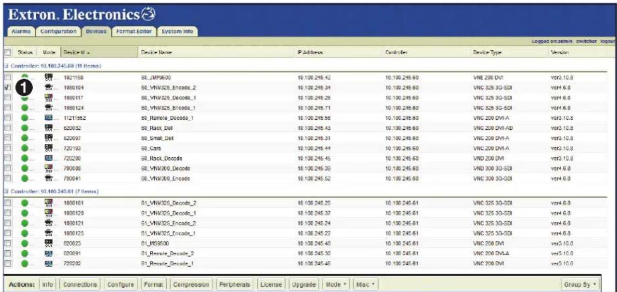
Figure 27. Encoder Actions Bar
The VNM 325 is selected in the example in figure 27 (outlined in red). Notice the check in the device selection box. When a device is selected, the Actions: bar at the bottom of the page enables all options, connections, and configuration for the device.
Actions Menu Bar Overview
The Actions menu bar buttons perform similar functions regardless of the device selected. The following is an overview of each button and the devices they are associated with.
- Info (all devices) — The Info button provides information about the device including the Device ID, Device Name, IP address (control and streaming), current status (active, inactive), and the network link status (poor, good). These items change depending on the selected device.
- Connections (Encoders, Decoders, VNS 104) — The Connections button provides a real-time display of the device connections.
- Configure (Encoders, Decoders, VNS 104) — The Configure button opens a dialog that provides the ability to name the device and enable the text overlay on the local display.
- Format (Encoders, Decoders, VNS 104) — The Format button opens a dialog that shows the current status of the device and allows selection and control of the input or output format, video and audio properties, and other configuration options depending on the selected device.
- Compression (Encoders and Decoders) — The Compression button opens a dialog used to configure the audio and video compression of the encoder and set the bitrate.
- Peripherals (Encoders and Decoders) — The Peripherals button configures the serial control port of the selected device.
- License (Encoders, Decoders, and Recorders) — The License button opens a dialog that shows information about the features that are enabled on the device.
- Upgrade (Encoders, Decoders, and VNR 100) — The Upgrade button opens a dialog that allows a firmware upgrade file to be downloaded to the selected device.
- Mode (Encoders, Decoders) — The Mode button opens a drop-down list used to set a selected codec device to either encoder or decoder operation.
- Misc (All) — The Misc button drop-down list has five options that include a real-time bandwidth monitor, a delete device function to remove the selected device from the device list, a multiple device licensing upgrade application, an OSD ID editor, and an application to issue HLI commands to the selected device.
- Recorder (Recorders only) — The Recorder button opens the recording browser to allow a user to select previously recorded streams. The browser provides information for each recording and allows users to manage the recordings of a selected device.
- Audio (VNS 104 only) — The Audio button opens the Configure Audio Settings dialog. This dialog sets the level for the audio stream and also allows it to be muted.
NOTE: Only one of the connected video streams is able to decode audio.
Device Configuration
The next section describes the general configuration of VN-Matrix devices and applies to VN-Matrix hardware encoders, decoders, and codecs.
- For details on the configuration of the VNM-250 see VNM 250 Configuration on page 64.
• For VN-Matrix recorders see Recorder Configuration on page 79. - For software decoders see VNS 104 Software Decoder Configuration on page 83.
- For a full description of a specific function, see the user guide for the device.
The menus change slightly between the encoders, decoders, and codecs. Where differences exist, they are noted.
VNM 200/225/300/325 Configuration
Info Menu
Click Info (see figure 26 on page 40) to open the Device Information dialog box to display basic information for the selected VN-Matrix device (see figure 28).

Figure 28. Device Information (Encoder or Decoder Shown)
The following fields are read-only (cannot be edited).
• Device ID — Displays the device ID number of the selected device.
• Device Name — Displays the name of the selected device.
• IP Address — Displays the IP address of the selected device.
- Device Status — The status of the selected device. Normally it shows Active and the quality of the link is indicated in the Link Status field. If the device is missing or cannot be contacted on the network, it shows No Device.
- Link Status — A link status of Good indicates little or no management packet loss. A link status of Fair indicates a small amount of packet loss. A link status of Poor indicates a bad link; investigate whether the link to the device has sufficient bandwidth to carry the data and management traffic.
Connections Menu
When devices are part of an active (launched) preset, the columns populate with the connection details of the selected VN-Matrix device (see figure 29). Click Connections to open the Connections dialog box.
VNM 200/225
| Connections | ||||
| Vice | Audio | Whiteboard | Data | |
| Description id Source Destination Locale Slot | 61_Decode2.videwindow 620023.1.0 0 239.192.1.42:5600 ext 0 | 61_Decode2.audiowindow 620023.0.0 0 239.192.0.42:9088 ext 0 | 61_Decode2.wbWindow 620023.2.0 0 239.192.2.42:10112 ext 0 | 61_Decode2.dataWindow 629023.5.0 0 239.192.3.42:10824 ext 0 |
| Description id Source Destination Locale Slot | 61_Decode3.videwindow 620009.1.0 0 239.192.1.42:5600 ext 0 | 61_Decode3.audiowindow 620009.0.0 0 239.192.0.42:9088 ext 0 | ||
VNM 300/325
| Connections | ||||
| Video | Audio | FEC Rows | FEC Cols | |
| Description id | 61_VNM300_Decode.videowindow 79008.1.0 | 61_VNM300_Decode.audiewindow 79008.0.0 | 61_VNM300_Decode.rowfscWindow 79008.5.0 | 61_VNM300_Decode.cefscWindow 79008.4.0 |
| Source | 0 | 10 | 0 | 10 |
| Destination | 239.192.1.52:9620 | 239.192.0.52:9108 | 239.192.2.52:10132 | 239.192.3.52:10644 |
| Locale slot | ext 0 ext 0 | ext 0 | ext 0 | ext 0 |
Figure 29. Connections Dialog Box
NOTE: The VN-Matrix 3xx connections dialog changes the Whiteboard column to FEC Rows and the Data column to FEC Cols.
The following fields are read-only (cannot be edited).
• Description — For a source, this field is the name of devices receiving a stream from the selected source. For a display, it has the name of the device providing the stream.
- id — Displays the device ID of the connected device.
- Source — For unicast transports, displays the IP address and port number of the source stream. For multicast transports this value is zero on an encoder.
- Destination — Displays the IP address and port number of the stream receiver device.
- Locale — This field displays loc when the data streaming between source and display are controlled by the same controller (loc). It displays ext if the data stream is exported across two different controllers or if the transport protocol is multicast RTP.
- Slot — This field displays information depending on the type of transport protocol used.
- For unicast RTP, the stream number is displayed. Four streams are available, numbered 0, 1, 2, and 3.
- For multicast RTP, this field displays for a source and -1 for a display.
Configure Menu
Click Configure to open the Configure Device Settings dialog box to set global parameters specific to the VN-Matrix 200/225 and 3xx devices (see figure 30).
Encoder Decoder
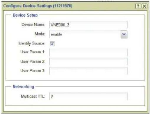

Figure 30. Configure Device Settings
Device Setup panel
- Device Name — Enter a name for the device in this field. This name appears in the device list and can be comprised of letters, numbers, and the underscore character. Spaces are not allowed.
• Mode — A device can be configured using one of four modes.
- enable — This is normal operation.
- disable — Use this mode on a source device to stop streaming to the network, but still show pass-through output. A display device outputs a splash screen.
- standby — Use this mode on a source device to stop streaming and also disable pass-through output. On a display device this mode disables all output.
-
test — Use this mode on a device (source or display) to show a splash screen with the words "Test Mode". Normal streaming is suspended.
-
Enable Splash Screen (Decoder Only) — Check this box to display a splash screen on the video output when no video stream is available.
- Identify Display (Decoder Only) — Check this box to show the device name on the connected display. The position and appearance of the label can be modified (see OSD Identifier Editor (Encoders and Decoders) on page 62).
- Identify Source (Encoder) — Check this box to display the name of the device on the image output to the loop-through connector. The source resolution and frame rate are displayed on the image that is otuput to the loop-through connector. The position and appearance of the label can be modified (see OSD Identifier Editor (Encoders and Decoders) on page 62).
- Identify Source (Decoder) — Check this box to display the name of the currently connected encoder on the connected display. The position and appearance of the label can be modified (see OSD Identifier Editor (Encoders and Decoders) on page 62).
- User Param [1, 2, 3] — These fields are used to enter user defined parameter names. When entering HLI or CLI commands into a control program from an external control system, the parameter names identify devices. The names can be comprised of letters, numbers, and the underscore character. Spaces are not allowed.
Networking panel
- Multicast TTL — This field specifies the number of hops multicast traffic can make between routed domains when it exits a source. It is not used for TCP or unicast RTP traffic.
Format Menu (Encoders)
Click Format to open the Source Format dialog box used to view information about the incoming source. It is also used to make adjustments to the signal and set the EDID options (see figure 31). The menu differs between the VN-Matrix 200/225 and VN-Matrix 3xx series.

VN-Matrix 200/225 Series VN-Matrix 3xx Series

Figure 31. Source Format Dialog Box
NOTES:
- The Status panel and Measured Video Properties panel contain fields that are read-only (cannot be edited).
- This menu works differently when a decoder or a display device is selected. For information on how to use the menu for decoders and display devices, see Format Menu (Decoders) on page 50.
Status panel
- Source — This field details the video input connection. Active means a video source is recognized at the input. Unplugged means no source is connected or there is no active video.
- Stream — When this field displays (1, 1) the source is recognized and ready to stream. When this field displays (0, 1) the source is either not connected or not recognized.
- Lock — If this field displays a value of 0, the VN-Matrix device has not locked on to the incoming source. A value of 1 indicates the VN-Matrix device has locked on to the source.
Measured Video Properties panel
This panel provides information about currently connected sources. The following fields are read-only (cannot be edited).
- Current Mode — This field details the current video resolution of the connected source. A complete list of supported resolutions is available in the VN-Matrix 200, VN-Matrix 225, VN-Matrix 250, VN-Matrix 300, and VN-Matrix 325 User Guides.
- Type — This field details the type of video format that is connected to the source.
NOTE: The VN-Matrix 200/225 reports DVI or analog. The VN-Matrix 3xx reports SDI.
• Line Count — This field details the total number of lines used in the connected source.
- Line Period (ms) — This field details how often the lines of information are updated in milliseconds (ms).
- Active Pixels — This field details the number of active pixels used in the connected source.
- Active Lines — This field details the number of active lines used in the connected source.
- First Pixel — This field details the position of the first active pixel in a line.
- First Line — This field details the position of the first active line in a frame.
- Phase — This field details the current waveform phase setting. The phase setting can be adjusted in the Input panel (see below).
Measured Audio Properties panel (VN-Matrix 200/225 only)
This panel provides the sampling rate of the incoming audio source for the VN-Matrix 200/225. The line is blank for the VN-Matrix 3xx (see Ancillary Audio Panel (VN-Matrix 3xx Only) on page 48 for audio details of the VN-Matrix 3xx).
Input panel (VN-Matrix 200/225 only)
This panel is only active for VN-Matrix 200/225 models and provides timing information for the connected analog sources.
NOTE: This panel is only active when configuring analog source types.
- Mode — VN-Matrix codecs support automatic video format detection for most standard source types. However, if a non-standard source type is used, the video format can be manually specified using this drop-down list.
- Phase — This drop-down list is used to adjust the waveform phase setting. This value should normally be set to auto. However, if a waveform suitable for automatic detection is not available, manually select a phase value to provide better image quality. Automatic phase adjustment maximizes the contrast between pixels. A good image for phase adjustment should have adjacent black and white pixels.
NOTE: Phase adjustment is only required on analog sources.
- Color Space — This drop-down list selects between RGB and YPbPr video source types.
NOTES:
- When auto is selected from the Mode drop-down list, the color space cannot be determined.
- Component sources are detected as an RGsB video type.
- Macrovision Defeat — Macrovision copy protection is often applied to commercially produced videos and DVDs. This adds additional sync level pulses to the waveform which must be ignored for proper video detection.
- Select this check box if the source contains content protected with Macrovision copy protection.
- Deselect this check box for all other sources. Selecting this check box for non-Macrovision sources may result in tearing at the top of the image.
Blanking panel (VN-Matrix 200/225 Only)
- Blanking — This drop-down list adjusts the blanking setting. This value is normally set to auto. However, if it is important that pixels on the very edge of the display are visible, setting this value to manual activates the Pixels and Lines fields so that offsets can be entered. The offsets are made relative to the First Pixel and First Line values of the source format selected on the Format Editor page (see Format Menu (Encoders) on page 45).
NOTE: Blanking adjustment is only required on analog sources.
- Pixels — This field is used to enter an offset to adjust the horizontal blanking. The value is entered as a positive (for example, 6) or negative (for example, -6) integer.
- Lines — This field is used to enter an offset to adjust the vertical blanking. The value is entered as a positive (for example, 6) or negative (for example, -6) integer.
EDID panel (VN-Matrix 200/225 Only)
- From Monitor — This field reports the EDID of the locally connected display. If no display is present or the display does not support EDID, No Device is reported. This is a read-only field (cannot be edited).
- To Source — This drop-down list specifies the EDID device type the VN-Matrix unit identifies itself as when connected to a source. Values are chosen from any of the stored EDID codes used on previously connected devices.
NOTE: If the transparent option is selected, the EDID of the last display or the currently connected display is reported.
Ancillary Audio Panel (VN-Matrix 3xx Only)
The VN-Matrix 3xx models replace the Input, Blanking, and EDID panels with an Ancillary Audio panel for audio configuration (see figure 32). Configuration options change depending upon the model and the transport mode selection. The differences are noted in the following descriptions.

Transparent Mode

Stereo Mode (VNM 325 Only)
Figure 32. Ancillary Audio Menus
• Audio Channels — This field reports the number of available audio channels.
• VN-Matrix 300: 4, 8, 12, or 16 depending on the number of licensed groups.
• VN-Matrix 325: Reads 16 when the transport mode is set to Transparent. Reads 2 when the transport mode is set to Stereo.
- Transport Mode — A drop-down list with two selections:
- Transparent: Audio is transported in groups of 4 channels. Multiple groups (see Selection Boxes below) can be selected for transport with payloads depending on the data: SDI (8 Mbps) or HDSDI/3G-SDI (16 Mbps).
Transparent mode is supported on both the VN-Matrix 300 and 325.
- Stereo: Audio is transported in stereo pairs. Only one pair can be selected at a time. Stereo pairs have a payload of 2.4 Mbps.
Stereo mode is supported on the 325 only.
- Selection Boxes — These boxes (Groups or Stereo Pairs), when checked, indicate different items depending on the selected transport mode.
- Transparent: Each box, when selected, indicates the number of audio groups that are transported with the video stream.
- VN-Matrix 300: The number of groups depends on the license of the connected device. The VN-Matrix 300 series can be licensed for up to four groups (see Audio Channels above).
• VN-Matrix 325: Up to four groups can be selected.
- Stereo: The selection boxes indicate the stereo pair selected for transport with the video stream. Only one stereo pair can be selected at a time.
- Audio Type (Stereo mode only) — This field reports the format of the audio data stream.
• PCM 24, 48 KHz: HDSDI and 3GSDI (typical)
• PCM 20, 48 KHz: SDI (typical)
- Compression (Stereo mode only) — This drop-down list selects the compression to apply to the stereo audio signal. The normal bitrate for a stereo pair is 2.4 Mbps.
- Pack 24: Sends all audio (20 or 24 bits) without compression and sends audio control data once per second.
- Pack 20: Same as Pack 24 except the least significant 4 bits of audio data are removed and set to zero. The bit rate is 1.92 Mbps.
- Pack 16: Same as Pack 24 except the least significant 8 bits of audio data are removed and set to zero. The bit rate is 1.54 Mbps.
- Decimate 2: Same as Pack 16 except the sample rate is reduced to half. The bit rate is 768 Kbps.
- Decimate 4: Same as Pack 16 except the sample rate is reduced to one-quarter. The bit rate is 384 Kbps.
- FEC Mode (Transparent mode only) — FEC (Forward Error Correction) can be applied to the ancillary audio to protect against errors caused by packet loss when the data is transported over a network. FEC enables the decoder to recreate data that has been lost or corrupted without the need for retransmission. The FEC data is sent separate from the image and ancillary data. The level of FEC can be set to protect against different levels of data loss. This produces a corresponding change in the amount of data that is transported and thus, the bit rate is increased or decreased in proportion to the amount of FEC applied.
- FEC Overhead (Transparent mode only) — This field reports the calculated overhead as a percentage of the signal bitrate.
- FEC Rows (Transparent mode only) — Row FEC protects against the loss of a single packet. It is the simplest method of protection and results in the lowest overhead in terms of bitrate and latency. However, it is not able to handle consecutive (burst) packet loss. Refer to the VN-Matrix 3xx Series User Guide for details on how to configure this setting.
- FEC Columns (Transparent mode only) — Column FEC protects against burst packet losses, providing that the burst of packet losses are not in the same row. Column FEC is known as 1D (dimension) FEC, as correction data is only calculated on one dimension. Refer to the VN-Matrix 3xx Series User Guide for details on how to configure this setting.
NOTES:
- The values set in the FEC row and column drop-down lists depend on the quality of the network link in use.
- The FEC data can add a large overhead to the overall bit rate. Some settings, while providing a high level of reliability, are inefficient.
- Settings that add little overhead may not provide a sufficient level of protection on networks with a poor Quality of Service (QoS).
- The recommended starting point for the FEC row and column error correction is 5,5.
Format Menu (Decoders)
When a decoder device is selected, click Format to open the Display Format dialog box used to configure the output format of a decoder (see figure 33 and figure 34). The menu differs slightly depending on the selected VN-Matrix device.
NOTES:
• The Current Format field is read-only (cannot be edited).
- This menu works differently when an encoder or a source device is selected. For information on how to use the menu for encoders and source devices, see Format Menu (Encoders) on page 45.
VN-Matrix 200/225 Display Format

Figure 33. VN-Matrix 200/225 Display Format Dialog Box
- Current Format — This read-only field displays the current output video format of the selected VN-Matrix device.
- When the Output Format field is set to auto, this field displays the resolution of the decoded stream. If an exact match is not possible, then this field displays Special followed by the available resolution closest to the decoded stream.
- When the Output Format field is not set to auto, this field displays the chosen resolution.
- If the Enable Splash Screen check box is selected and the device is not connected to a stream (or not decoding), this field displays splash screen 1024x768.
- Output Format (VN-Matrix 200/225 only) — This drop-down lists contain preset output video formats, plus an additional auto option. Selecting a preset format forces the output of the VN-Matrix device to the selected format. Selecting auto matches the output video format to the native resolution of the decoded stream.
NOTE: When a preset output format is selected, the Scale to Output Format check box must be selected.
- Scale to Output Format (VN-Matrix 200/225 only) — When selected, this check box enables scaling of the decoded stream to the resolution selected in the Output Format drop-down list. Upscaling and downscaling are supported.
NOTES:
- For smooth playback, select an output format with approximately the same frame rate as the source.
- Scaling adds two frames of latency to the delay between source capture and display output.
- Scaling is disabled when auto is selected in the Output Format drop-down list or when the scaling ratio is 1:1
- Sync on Green (SoG) (VN-Matrix 200/225 only) — This check box, when selected, enables Sync on Green on the output analog waveform. When SoG is enabled, separate horizontal and vertical syncs are present on the analog output.
NOTE: SoG is currently limited to the output of progressive modes. If an interlace mode is selected, the SoG request is ignored.
- Playback Delay (s) — This field is used to enter the amount of time (in seconds) that the display waits before playing back the source stream.
VN-Matrix 3xx Display Format

Figure 34. VN-Matrix 3xx Series Display Format Dialog Box
The VN-Matrix 3xx series display format dialog box shares two configuration options with the VN-Matrix 200/225:
- Current Format
- Playback Delay (s)
These configuration options function identically to those on the VN-Matrix 2xx series Display Format menu.
Genlock is added to the VN-Matrix 3xx menu, selected with the check box:
- Genlock — When selected, enables a local SDI source with the same refresh rate as the streamed video to act as a digital genlock signal to synchronize the decoder.
Compression Menu (Encoders Only)
When an encoder device is selected, click Compression to open the Compression Settings dialog box used to set the amount of compression on the encoded source (see figure 35).

VNx 200/225 Series VNx 3xx Series

Figure 35. Compression Dialog Box
The configuration options have a direct effect on the network bandwidth required for the encoded stream.
- Increasing compression decreases the network bandwidth requirements for the stream.
• Decreasing compression increases the network bandwidth requirements for the stream.
Alternatively, the desired bandwidth can be set using the Bitrate panel (see page 53) and the VN-Matrix adjusts compression and frame rate to meet the specified bandwidth limit.
NOTE: This menu is only available when an encoder device is selected.
Video Compression panel
• Transform (VN-Matrix 2xx only) — Two transform types are supported.
- graphics — Optimizes the video to support text and sharp lines, such as are present on most computer screens.
-
video — Optimizes the video to support smooth tone changes such as are present in movies and other video content.
-
Luma Compression — This drop-down list sets the amount of compression on the luma (black and white) portion of the signal. A value of 1 is the minimum amount of compression available; a value of 10 is maximum compression.
- Chroma Compression — This drop-down list sets the amount of compression on the chroma (color) portion of the signal. A value of 1 is the minimum amount of compression available; a value of 10 is maximum compression.
NOTE: This field is available only when the Luma/Chroma Lock is not selected.
- Luma/Chroma Lock — Selecting this check box automatically sets the chroma compression value higher than the Luma Compression setting.
When the check box is selected, the Chroma Compression field tracks the Luma Compression field by a fixed value of +1 (Luma Compression = 1) or +2 (Luma Compression > 1).
- Temporal Compression — Selecting this check box causes areas of the screen to refresh only when a change between frames is detected. Enabling temporal compression can significantly reduce network bandwidth.
NOTE: For all normal operation, Temporal Compression should be enabled.
- Refresh Rate — This field controls how frequently static parts of the screen are updated when the Temporal Compression check box is selected. This is useful when connecting new displays to a temporally encoded source and fills in gaps in the data when using a lossy network transport (such as RTP). A value of 1 refreshes the screen once a second; a value of 10 refreshes the screen once every ten seconds. A value of 0 disables the refresh. Valid settings are 1 though 17.
- Threshold — This drop-down list controls the sensitivity of the temporal change detection algorithm. A value of 0 means any screen changes will be sent. Increasing the value increases the send threshold and reduces the network bandwidth. A setting of 0 is suitable for DVI computer generated sources. Sources with more noise or video-type motion should use a setting between 1 and 4. Camera sources should always use values greater than 0.
- Chroma Threshold — This check box controls whether the temporal algorithm should consider changes in the color (chrominance) of the image. Selecting this check box provides better results when using digital simulation type sources. However, this can increase the transmit bandwidth by up to 200%, so it should be disabled on bandwidth sensitive systems.
NOTE: This option is normally not required for video or camera type sources.
- Motion (VN-Matrix 2xx only) — This drop-down list is used to adjust motion compression. The value can be set from to 15, where is no additional motion compression and 15 is full motion compression. When enabled, motion detected on the area of the screen is heavily compressed. This reduces bandwidth when the eye cannot perceive significant detail due to the motion. When motion stops, the video is resent at the standard resolution preserving screen integrity.
Audio Compression panel (VN-Matrix 200/225 only)
NOTE: The audio compression settings for the VNM 3xx series are located in the source format menu (see Ancillary Audio Panel (VN-Matrix 3xx Only) on page 48).
- Compression — VN-Matrix supports limited compression of S/PDIF audio sources. This is controlled by the Compression setting. The S/PDIF digital data bus can carry two types of data: 2-channel uncompressed audio and encoded digital data, the latter often in AC-3 (Dolby Digital) format. The following compression values are supported.
| Available Compression Settings | ||
| Compression Stereo | Audio Tracks AC-3 Data Track | Track |
| No compression | 24 bit native data (2975 kbps) | 24 bit native data (2975 kbps) |
| 24-bit to 16-bit | 16 bit data, full sample rate (1517 kbps) | 16 bit data, zeros run length encoded (430 kbps) |
| 44 kHz to 22 kHz | 16 bit data, 1/2 sample rate (784 kbps) | 16 bit data, zeros run length encoded (430 kbps) |
| 44 kHz to 11 kHz | 16 bit data, 1/4 sample rate (418 kbps) | 16 bit data, zeros run length encoded (430 kbps) |
Bitrate panel
The Bitrate panel sets a specific bandwidth limit for the encoded stream.
- Limit Mode — This drop-down list contains management modes that limit the instantaneous traffic on the network and drops traffic when the bandwidth rate is exceeded. This is useful when the network connection between the source and display has limited bandwidth.
NOTE: Rapidly changing content may produce instantaneous peaks in bandwidth rate when using PBR-F management mode.
Six bandwidth management modes are supported.
- None — This mode does not use bandwidth management. Only the underlying compression settings are managed.
-
Manual Frame Drop — This mode allows the user to specify the precise fraction of frames to drop. This mode does not manage the bandwidth rate at a fixed level, but does result in a smoother display update when using rapidly changing video content types.
-
Shared Flowrate (FD) — This mode limits the total video network traffic for the source. Frames are dropped if the instantaneous data rate is higher than the flowrate entered in the Target Rate (Mbps) field.
- Peak Flowrate (FD) — This mode limits the video network traffic for a single source stream. Frames are dropped if the instantaneous data rate is higher than the flowrate entered in the Target Rate (Mbps) field. Using N output streams increases the bandwidth N times unless the multicast RTP transport protocol is used.
- PBR-F — This mode dynamically modifies the compression settings to limit the transmitted bandwidth depending on the specified value entered in the Target Rate (Mbps) field. The specified Compression setting is used as the minimum compression value. This control mode averages the bit rate over a period of two frames.
- PBR-F (FD) — This mode is the same as PBR-F except frames are dropped when a larger bandwidth reduction (such as a reduction that cannot be achieved with compression settings alone) is required.
- Target Rate (Mbps) — This field is used in all bandwidth management modes (except Manual Frame Drop) to specify the network bandwidth used by the source. This value is specified in Megabits per second (Mbps).
- Frame Drop (%) — This field is used in Manual Frame Drop mode and specifies the percentage of frames to discard. A value of 95% discards 19 out of every 20 frames reducing a 60 frames per second (fps) video signal to 3 fps. 1 fps is the minimum frame rate. A value of 99% results in all frames being dropped due to rounding.
Peripherals Menu
Click Peripherals to open the Peripherals Settings dialog box to manage remote keyboard and mouse communications on a VN-Matrix 200/225 (see figure 36).
NOTE: Mouse and keyboard functions are supported by VN-Matrix 2xx series devices only. For a complete description, see the device user guide at www.extron.com.
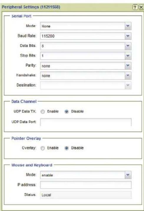
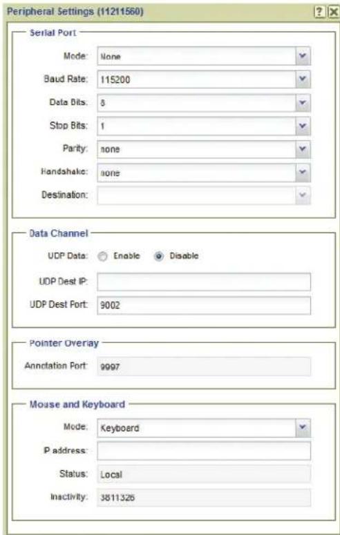
Encoder Decoder
Figure 36. Peripherals Dialog
Serial Port
The serial port panel configures the RS-232 port on VN-Matrix encoder and decoder devices. For a full description of the serial port configuration, including server/client setup, see the User Guide for the device. Default settings are shown in figure 36.
• Mode: — The serial port can operate in one of three modes:
• None: The serial port is not used.
• Pass-through server: The serial port acts as a destination for serial port clients.
• Pass-through client: The serial port connects to server serial ports on other devices
A point to point link can be established by setting the serial port of one VN-Matrix device to pass-through server mode and a second device to pass-through client mode. The destination of the second device is set to the pass-through port on the first (server) device.
A server can accept multiple client connections. Under these conditions the data input by the server serial port is duplicated to all connected clients. The data received from the clients is multiplexed (in order of arrival) and output through the server serial port.
- RS-232 Settings: Basic configuration of the serial port includes baud rate, data bits, stop bits, parity, and handshake.
- Destination: — This option can only be modified when the serial port is in client mode. The dropdown list allows a passthrough connection request from each VN-Matrix device in the network, regardless of whether the device is currently configured as a server.
Data Channel
The data channel panel configures the UDP data stream.
- UDP Data Tx (encoder) — Enables or disables UDP data transport through the dataport.
- UDP Data Port (encoder) — The port number to receive UDP traffic on. This setting must match the port number defined by the external device or system that generates the UDP data.
- UDP Data RX (decoder) — Enables or disables the UDP data.
- UDP Dest IP (decoder) — The IP address of the external device or system that receives UDP traffic. UNICAST or MULTICAST addresses are valid.
- UDP Dest Port (decoder) — This is the port number used by the (external) device or system to receive the UDP data.
Pointer Overlay
• Overlay (encoder) — Enable the overlay pointer on the local loop-through display.
- Annotation Port (decoder) — Read-only value of the annotation port.
Mouse and Keyboard
• Mode: — Device specific.
-
Encoder: Enabled, allows mouse and keyboard forwarding.
• Decoder: This control has four options: -
Disable: The decoder does not forward mouse and keyboard information.
• Keyboard: The decoder forwards mouse and keyboard information. - Keyboard + keepalive: The link is automatically established if broken.
• Force: Mouse and keyboard forwarding + keepalive is permanently enabled.
- IP Address: —
- Encoder: Not Required.
- Decoder: Used to specify the IP address of the target encoder when the transport is multicast or when the encoder exists on a different controller domain.
NOTE: Leading zeros are not allowed.
- Status: — Read-only, is the current status of the Link.
- Encoder: Disabled, local, or remote keyboard and mouse is displayed.
- Decoder: Disabled, local, or forwarding is displayed. In case of a connection error, a reason is shown in brackets.
- Inactivity: Read-only, (decoder only). Displays the number of seconds since the mouse or keyboard reported a change
License Menu
Click License to open the Device License Management dialog box. This dialog displays the enabled features on the selected unit and also enables optional features (see figure 37).

VN-Matrix 200/225 VN-Matrix 3xx

Figure 37. License Menu
NOTE: The Licensed Features panel and Current Structure panel contain fields that are read-only (cannot be edited).
Licensed Features panel
The Licensed Features panel details the features currently enabled on the device.
• Video (all) — Details the input signal format type.
• Audio (all) — Details the number of supported audio channels.
• Video Scaler (VNM 200/225) — Details if video scaling is enabled or disabled.
- Whiteboard (VNM 200/225) — Details if whiteboard data streaming is enabled or disabled.
• Data (VNM 200/225) — Details if data streaming is enabled or disabled.
Current Structure panel
- Hardware ID (VNM 3xx only) — Displays the hardware ID of the device.
• Structure (all) — Details the current structure key used by the selected device. - Checksum (all) — Details the current checksum used by the selected device.
Change Device Structure panel
NOTE: See Update a device license below for information on updating the structure key and checksum.
ATTENTION:
• Structure — This field is used to update the structure key used by the device.
- Checksum — This field is used to update the checksum used by the device.
Update a device license
To obtain and install a new device license, follow the procedure below.
-
Contact the Extron S3 Sales and Technical Support Hotline and provide the following information.
-
The device ID of the VN-Matrix device. This can be obtained from the back of the device.
-
The order number of the VN-Matrix device.
-
The Extron S3 Sales and Technical Support Hotline provides a structure key and a checksum.
• Enter the structure key into the Structure field.
- Enter the checksum into the Checksum field.
- Click Update License to save the new license.
Upgrade Menu (2xx and 3xx Devices)
Click Upgrade to open the Upgrade Device Firmware dialog box used to upgrade the firmware of one or more VN-Matrix devices (see figure 38, on the next page).
ATTENTION:
Figure 38. Upgrade FW Dialog
- Select a Version — This drop-down list contains previously uploaded firmware versions that are available.
- Upload New Version — Click Browse to upload new firmware versions. New firmware versions uploaded to the VNM Enterprise Controller are added to the Select a Version drop-down list.
To upgrade the firmware:
- Select a device or multiple devices from the Devices page (see About the Devices Page on page 36).
- Click Upgrade on the Actions toolbar.
- Select the desired version from the Select a Version drop-down list and click Upgrade.
If the desired version is not available in the Select a Version drop-down list:
- Select a device or multiple devices from the Devices page (see About the Devices Page).
- Click Upgrade on the Actions toolbar.
- Click Browse and navigate to the appropriate location of the firmware. When the firmware is selected, it is uploaded to the VNM Enterprise Controller.
- After the proper firmware is uploaded, select the version from the Select a Version drop-down list and click Upgrade.
NOTES:
- If a VN-Matrix device selected for upgrade already contains the latest version of firmware, the upgrade status displays "Wait". If multiple devices are selected for upgrade, the devices already containing the firmware upgrade display "Wait" while the other devices are upgraded (see figure 39).
- See Update a device license on page 58 for information on updating the structure key and checksum.
- The firmware for the VN-Matrix 2xx series differs from the firmware for the VN-Matrix 3xx series. Upgrading multiple devices is possible only when selected devices are either all VN-Matrix 2xx series or all VN-Matrix 3xx series.
- The VNM Recorder can not be upgraded from this page (see the VNM Recorder User Guide at www.extron.com).

Figure 39. Device Firmware Upgrade Status
Mode Menu (VNC Devices Only)
The mode menu assigns VN-Matrix codec devices as decoders or encoders.
NOTE: Choosing a mode or toggling a device between an encoder and a decoder can take a few seconds after the selection is made.
To configure a codec device as a decoder or encoder:
-
Select a codec device or multiple codec devices from the Devices page (see About the Devices Page on page 36).
-
On the action toolbar, click Mode (①).
The Mode menu opens.

- Select Decoder to set the codec as a display device or select Encoder to set the codec as a source device.
Misc Menu
This menu contains five selections (see figure 40).
• Real-time Bandwidth Monitor
- Delete Device
• Multiple Device Licensing
- OSD Identifier Editor
- Send HLI command

Figure 40. Misc Menu
Real-time Bandwidth Monitor
Select the real-time bandwidth monitor to open a new dialog box that monitors the bandwidth (measured in Mbps) used by the selected device or devices (see figure 41).
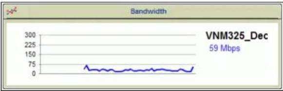
line
| Bandwidth | Value | | --------- | ----- | | VNM325_Dec | 59 Mbps |Figure 41. Bandwidth Monitor
NOTE: Bandwidth data is displayed only for decoder devices. A graph is displayed for an encoder, but the data always shows ∅ Kbps.
Delete Device
Select this option to delete the selected device or devices.
NOTES:
- Be certain the appropriate devices are selected when using this menu option. The selected devices are deleted right away; no notification or warning is given when the option is selected.
- A device can only be deleted when it is offline. Active devices can not be removed from the device list.
Multiple Device Licensing
Select this option to open a dialog box to upgrade the feature sets of multiple devices simultaneously.
NOTE: This option is not available on the VND 250.
OSD Identifier Editor (Encoders and Decoders)
Select this option to customize the appearance of the on-screen display for the selected device or devices (see figure 42).

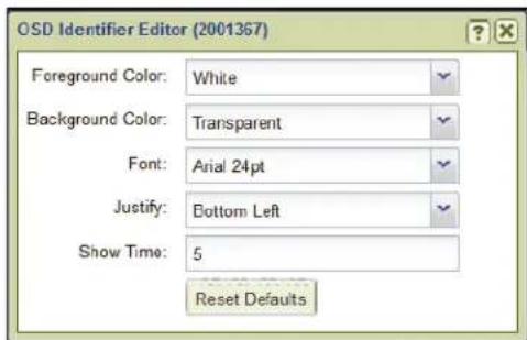
VNM 200/225/300/325 VNE 250, VND250, VNS 104
Figure 42. OSD Identifier Editor
• Foreground Color — This drop-down list selects the color of the text box font.
• Background Color — This drop-down list selects the text box background color.
- Font — This drop-down list selects the type of font used in the text block.
- X — This field selects the X (horizontal) position for the text block. The value is a percentage of the screen width and references the center of the text block.
- Y — This field selects the Y (vertical) position for the text block. The value is a percentage of the screen height and references the center of the text block.
- Justify — This drop-down list places the text block in one of nine fixed positions.
• Show Time — Sets the length of time (in seconds) the name of the source device is visible after a connection is made. A value of keeps the name visible indefinitely.
NOTES:
- This control option only functions when the Identify Source check box is selected on the Configure menu (see Configure Menu on page 44).
• The OSD is not recorded. - See VNS 104 Software Decoder Configuration on page 83 for VNS 104 OSD options.
Send HLI Command
Selecting this option opens a dialog box used to send High Level Interface (HLI) command strings to VN-Matrix devices (see figure 43).

Figure 43. HLI Command Window
To send a command:
- Click in the (enter command line) text field.
- Type the command.
- Press
.
NOTE: The response is returned in the response area of the dialog box.
Example HLI commands and information on how to use them are available in System Control on page 175.
Group Menu
See Sorting Devices by Group on page 39 for information on using this menu.
VNM 250 Configuration
The VND 250 and VNE 250 add HDMI input and output capability to the VN-Matrix system. Several configuration items have been added to the normal encoder and decoder configuration pages for HDMI and HDCP compatibility.
Info Menu (VNM 250)
The Info action bar dialog adds two LAN port connection entries for separate control and streaming connections. Click Info to open the Device Information dialog box that displays basic information for the selected VNM 250 (see figure 44).
VNE 250

VND 250

Figure 44. Device Information - VNM 250
The following fields are read-only (cannot be edited).
• Device ID — Displays the device ID number of the selected device.
• Device Name — Displays the name of the selected device.
• LAN 1 IP (Control) — Displays the IP address of the control port.
• LAN 2 IP (Streaming) — Displays the IP address of the streaming port.
- Device Status — The status of the selected device. Normally it shows Active and the quality of the link is indicated in the Link Status field. If the device is missing or cannot be contacted on the network, it shows No Device.
- Link Status — A link status of Good indicates little or no management packet loss. A link status of Fair indicates a small amount of packet loss. A link status of Poor indicates a bad link; investigate whether the link to the device has sufficient bandwidth to carry the data and management traffic.
Configure Menu
Click Configure to open the Configure Device Settings dialog box and set global parameters specific to the VNM 250 devices (see figure 45).

Figure 45. VNM 250 Configure Device Settings
Device Setup panel
• Device Name — Enter a name for the device (see Device Setup panel on page 44).
• Mode — A device can be configured using one of four modes.
- enable — This is normal operation.
- disable — On a source device, stops streaming to the network, but still shows pass-through output. A display device outputs a splash screen.
- standby — Use this mode on a source device to stop streaming and also disable pass-through output. On a display device this mode disables all output.
-
test — Use this mode on a device (source or display) to show a splash screen with the words "Test Mode". Normal streaming is suspended.
-
Enable Splash Screen (decoder only) — Check this box to display a splash screen on the connected display or device when no video is available.
- Identify Device — Check this box to show the device name on the pass-through output. The position and appearance of the label can be modified.
- Identify Source (Encoder) — Check this box to display the name of the device on the image output to the loop-through connector. The source resolution and frame rate are displayed on the image that is otuput to the loop-through connector. The position and appearance of the label can be modified (see OSD Identifier Editor (Encoders and Decoders) on page 62).
- Identify Source (Decoder) — Check this box to display the name of the currently connected encoder on the connected display. The position and appearance of the label can be modified (see OSD Identifier Editor (Encoders and Decoders) on page 62).
- Flash LCD — Check this box to flash the front panel of the selected device. This assists users with identifying an individual device within a large system.
- User Param [1, 2, 3] — These fields are used to enter user defined parameter names (see Device Setup panel on page 44).
Networking panel
- Multicast TTL — This field specifies the number of hops multicast traffic can make between routed domains when it exits a source. It is not used for TCP or unicast RTP traffic.
Connections Menu
When devices are part of an active (launched) preset, the columns in the Connections menu populate with the connection details of the selected VN-Matrix device (see Connections Menu on page 43). The Connections dialog adds the location of the return audio path to the columns.
Format Menu (VNE 250)
Select the VNE 250 and click Format from the action bar to open the source menu. Status, Measured Video Properties, Measured Audio Properties, and EDID panel configuration is the same as the VNM 200/225/300/325 device (see Format Menu (Encoders) on page 45).
Input Configuration and Audio (VNE 250 Only)
The VNE 250 adds an input selection, HDCP authorization, program audio selection, and return audio selection.
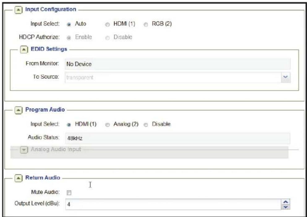
Figure 46. VNE 250 Source Format
- Input Configuration — Click the desired input option.
- Auto: When enabled, the HDMI input is automatically selected whenever a digital source is detected.
The EDID settings become read only in this mode.
• HDMI (1): Selects the HDMI input. The EDID Settings panel is active.
• RGB (2): Selects the RGB input. The EDID Settings panel is active. - HDCP Authorize: When an HDMI signal is detected, enable or disable HDCP authorization.
• EDID Settings — Select the EDID source from two choices.
- From Monitor: This read-only field reports the EDID of the locally connected display. If no display is present or the display does not support EDID,
- To Source: This drop-down list specifies the EDID device type the VN-Matrix unit identifies itself as when connected to a source. Values are chosen from any of the stored EDID codes used on previously connected devices or from a fixed list of input formats.
NOTE: If the transparent option is selected, the EDID of the last display or the currently connected display is reported.
- Program Audio — Click the desired audio input.
- Input Select: Selects the input audio source. HDMI audio is not supported if RGB (2) input video is selected.
• HDMI (1): Selects the embedded HDMI audio.
- Analog (2): Selects the rear panel analog audio input.
- Disable: Mutes all audio inputs.
- Audio Status: Read-only field that displays the sampling rate of the selected audio source.
- Analog Audio Input — Available only when the audio source is set to Analog.
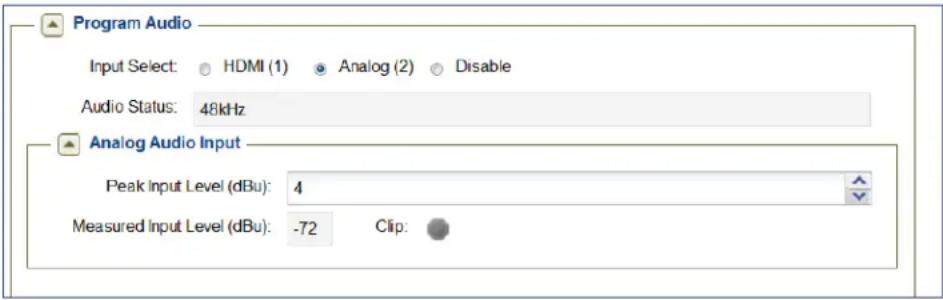
- Peak Input Level (dBu): Optimize Signal to Noise Ratio (SNR) prior to the Analog to Digital Conversion (ADC) process. Set the Peak Input Level to a value just above the highest level of the source audio material. For example, if the input level from the source material peaks at +3 dBu, the Peak Input Level is set to +4 dBu.
The range is -26 to 12 dBu. Default is +4 dBu.
- Measured Input Level (dBu): This field shows the current measured input level of the analog input source in dBu. The value is updated every second and can be used as a guide to determine the Peak Input Level (see above) of the source material. If the measured input level exceeds the specified peak input level, the Clip warning indicator glows red. When the input level falls back within range, the warning indicator remains lit for three seconds and then turns off.
- Return Audio — Controls the audio level for audio received from a decoder. Only one decoder receiving an audio stream from an encoder can send return audio to the source or connected audio device. Only analog audio is supported for return audio.
- Mute Audio: Mutes the return audio.
- Output Level (dBu): Only available when a connection is made to a decoder. Adjust the audio level of the rear panel return audio output.
The range is -70 to +12 dBu. Default: +4 dBu.
Format Menu (VND 250)
The VND 250 Display Format dialog shares two configuration options with the VN-Matrix 200/225:
- Current Format
- Output Format
These two configuration options function identically to those on the VN-Matrix 200/225 (see Format Menu (Decoders) on page 50).

Figure 47. VND 250 Display Format Dialog Box (Decoder)
The following configuration options are added:
- Scale Mode — Select fill or follow.
- Fill scales the output video to fill the entire screen of the connected display. The aspect ratio is not maintained.
- Follow keeps the output format the same as the input, maintaining the aspect ratio and adding black bars as needed.
NOTE: Scale mode options are not available when the output format is set to Auto.
- HDCP Mode — The HDCP mode control is used to set the encryption negotiation method between the decoder and an HDCP compliant display.
- Auto: HDCP negotiation occurs each time a new stream is decoded. Encryption is set automatically, dependent on the decoded stream.
Encryption is enabled if the decoded stream is protected and disabled if not.
- On: Encryption is forced on (enabled) at all times regardless of the decoded stream type.
Forcing encryption results in a cleaner switching transition between encrypted and non-encrypted content.
- Genlock — Enables the synchronization of the output to a reference waveform. The VND 250 uses TTL level signaling which is not compatible with normal genlock sources.
- Enable: Setting this option enables the decoder output to lock to an incoming genlock signal generated by another VND 250 device.
- Disable: The decoder output is locked to its own internal timing reference. Any incoming genlock signal is ignored.
- Framelock Ref: This drop-down control is used with the genlock control described above. It defines which VND 250 device is used as the frame reference in a genlock group. When such a group is formed, a network-based protocol permits the chosen VND 250 to coordinate frame timing so that all decoders are showing frames captured at the same time.
- Channel Delay(s) — The channel delay is unique to each channel of video, audio, data or whiteboard data and is set in seconds. In normal operation on a LAN, Channel Delay is set to 0.0.
- Frame Delay — The frame delay can only be modified on the video channel and is converted from frames to seconds depending on the video mode the decoder is currently receiving. In normal operation on a LAN, Frame Delay is set to 6 frames.
- Total Delay(s) — The delay time between the data being input to the encoder and output on the decoder is controlled by setting the Channel Delay(s) and the Frame Delay. The Total Delay(s) time shown in this read-only field is the sum of the two values.
Where synchronization between channels is required, either between video and audio on one device or between video channels on multiple devices, the default values (Channel Delay: 0.0, Frame Delay: 6) results in an end to end delay of 100ms on a 60 fps signal. On a WAN, the Channel Delay parameter can be used to add an amount corresponding to the one-way network delay (half of the round trip time [RTT]).
The hardware has a minimum delay requirement of 2.5 frames in progressive mode and 3.5 fields in interlace mode. Setting a Total Delay less than these values results in uneven playback and pipeline underflow alarms. There is one exception to this rule. Setting the Total Delay to 0.0 (zero) places the system in a special minimum-latency mode.
Excessively long delays cause data to build up in a software buffer within the decoder. When the build up is more than 10 video frames, frames of data are discarded which can result in on-screen artifacts.
Videowall panel (not available when output format is set to Auto)
The Videowall configuration settings allow a video stream from a single source to split over several decoders, each attached to one monitor of a videowall layout. The number of monitors that make up the full size of the wall and the selected decoders position in the wall must be configured for each decoder.
The videowall can be as large as 5 monitors tall by 5 monitors wide in any variation. The decoder segments its portion of the full video into the proper size based on the two size entries and the position of the connected monitor.
Size tells the decoder how many total monitors (and decoders) make up the videowall. For instance, in the videowall example below, H size is 2 and V size is 2 indicating a 2x2 videowall resulting in four segments of the full video.
Position is the location of the monitor as part of the entire wall and tells the decoder which segment of the full video it displays. Numbering always begins with the upper left monitor.
- Size (H) — 1 to 5
- Size (V) — 1 to 5
- Position — 0 to 25. Position 0 ignores the size entries and displays the full video on the connected display. The top left monitor as the user views the videowall is position 1. Numbering runs left to right and top to bottom from that point as shown.
Example: The selected decoder is connected to the video monitor in the lower left of the 2x2 videowall shown at right. The configuration is:
| 1 | 2 |
| 3 | 4 |
- Size (H)—2: indicates the videowall is 2 monitors wide.
- Size (V) — 2: indicates the videowall is 2 monitors tall.
- Position — 3: selects the segment of the full video the decoder outputs.
Bezel Compensation panel (Mullion Compensation)
In Videowall mode, the bezel compensation settings correct image geometry when the decoded image is spread across displays that have a mullion. The settings in the horizontal and the vertical adjustments are applied equally to both edges.
• Horizontal — 0 to 100%
• Vertical — 0 to 100%
Configuring for Videowall
In addition to the size, bezel compensation, and position settings, when configuring a group of decoders for videowall use, the following settings are also required:
- Output Format — Select the same output resolution for all decoders in the group.
- Scale Mode — Select Fill for all decoders in the group.
NOTE: The aspect ratio of the decoded source image is not maintained.
- Genlock and Framelock settings — All decoders are configured as a genlock group (see Genlock on the previous page).
NOTE: The image quality of a single source that is scaled across multiple displays, depends on the compression applied to the source and the size of the final image. The recommended maximum videowall size is three displays horizontal by three displays vertical. It is further recommended that displays used in a videowall be the same type, resolution, and size.
Program Audio Output panel
- Output Select—Select HDMI audio, analog audio, both, or none.
- Analog Audio Output Level (dBu) — Sets the analog output level from a range of -26 to +12 dBu.
- Decode Buffer Settings Channel Delay(s) — Configured the same as the video channel delay (see Channel Delay(s) on page 69).
Return Audio Input panel
- Peak Input Level (dBu)—To optimize signal-to-noise ratio (SNR) prior to the Analog to Digital Conversion (ADC) process, the Peak Input Level is set to a value just above the highest level of the source audio material. For example, if the input level from the source material peaks at +3 dBu, the peak input level is set to +4 dBu. The range is -26 to +12 dBu.
- Measured Input Level (dBu) — This read-only field shows the audio level of the analog input source in dBu. The value is updated every second and can be used as a guide to determine the Peak Input Level (see above) of the source material. If the measured input level exceeds the specified peak input level, the Clip warning indicator glows red. When the input level falls back within range, the warning indicator remains lit for three seconds and then turns off.
Compression Menu (VNE 250 Only)
With an encoder device selected, click Compression to open the Compression Settings dialog box to set the amount of compression on the encoded source (see figure 48).

Figure 48. Compression Dialog Box (Encoder Only)
These configuration options have a direct effect on the network bandwidth required for the encoded stream.
- Increasing compression decreases the network bandwidth requirements for the stream.
• Decreasing compression increases the network bandwidth requirements for the stream.
Alternatively, the desired bandwidth is set using the Bitrate panel to meet the specified bandwidth limit.
Video Compression panel
• Transform — Two transform types are supported.
- graphics — Optimizes the video to support text and sharp lines, such as are present on most computer screens.
- video — Optimizes the video to support smooth tone changes, such as are present in movies and other video content.
- Luma Compression — This drop-down list sets the amount of compression on the luma (black and white) portion of the signal. A value of 1 is the minimum amount of compression available; a value of 10 is maximum compression.
- Chroma Compression — This drop-down list sets the amount of compression on the chroma (color) portion of the signal. A value of 1 is the minimum amount of compression available; a value of 10 is maximum compression.
NOTE: This field is available only when the Luma/Chroma Lock is not selected.
- Luma/Chroma Lock — Selecting this box disables the Chroma Compression field and automatically sets chroma compression two levels higher than Luma Compression.
When selected, the Chroma Compression field tracks the Luma Compression field by a fixed value of +1 (Luma Compression = 1) or +2 (Luma Compression > 1).
- Temporal Compression — Selecting this check box causes areas of the screen to refresh only when a change between frames is detected. Enabling temporal compression can significantly reduce network bandwidth.
NOTE: For all normal operation, Temporal Compression should be enabled.
- Refresh Rate — This field controls how frequently static parts of the screen are updated when the Temporal Compression check box is selected. This is useful when connecting new displays to a temporally encoded source and fills in gaps in the data when using a lossy network transport (such as RTP). A value of 1 refreshes the screen once a second; a value of 10 refreshes the screen once every ten seconds. A value of 0 disables the refresh. Valid settings are 1 though 17.
- Threshold — This drop-down list controls the sensitivity of the temporal change detection algorithm. A value of means any screen changes will be sent. Increasing the value increases the send threshold and reduces the network bandwidth. A setting of is suitable for DVI computer generated sources. Sources with more noise or video-type motion should use a setting between 1 and 4. Camera sources should always use values greater than .
- Chroma Threshold — This check box controls whether the temporal algorithm should consider changes in the color (chrominance) of the image. Selecting this check box provides better results when using digital simulation type sources. However, this can increase the transmit bandwidth by up to 200%, so it should be disabled on bandwidth sensitive systems.
NOTE: This option is normally not required for video or camera type sources.
- Motion — This drop-down list is used to adjust motion compression. The value can be set from 0 to 15, where 0 is no additional motion compression and 15 is full motion compression. When enabled, motion detected on the area of the screen is heavily compressed. This reduces bandwidth when the eye cannot perceive significant detail due to the motion. When motion stops, the video is resent at the standard resolution preserving screen integrity.
Audio Compression panel
- Compression — VN-Matrix devices support limited compression of audio sources. The S/PDIF digital data bus can carry two types of data: 2-channel uncompressed audio and encoded digital data, the latter often in AC-3 (Dolby Digital) format. If the source is HDMI AC-3, run length encoding (RLE) is applied that results in an output bandwidth of about 430 kbps. If the source is HDMI PCM, the full set of compression values is used.
The following compression values are supported:
| Compression Stereo Audio Tracks AC-3 Audio Track | ||
| No compression (~3 Mbps) | 24 bit native data (2975 kbps) 24 bit native data (2975 kbps) | |
| 24-bit to 16 bit (~1.5 Mbps) | 16 bit data, full sample rate (1517 kbps) | 16 bit data, zeros run length encoded (430 kbps) |
| 44 kHz to 22 kHz (~800 kbps) | 16 bit data, half sample rate (784 kbps) | 16 bit data, zeros run length encoded (430 kbps) |
| 44 kHz to 11 kHz (~400 kbps) | 16 bit data, quarter sample rate (418 kbps) | 16 bit data, zeros run length encoded (430 kbps) |
Bitrate panel
The Bitrate panel sets a specific bandwidth limit for the encoded stream.
- Limit Mode — This drop-down list contains management modes that limit the instantaneous traffic on the network and drops traffic when the bandwidth rate is exceeded. This is useful when the network connection between the source and display has limited bandwidth.
NOTE: Rapidly changing content may produce instantaneous peaks in bandwidth rate when using PBR-F management mode.
Six bandwidth management modes are supported.
- None — This mode does not use bandwidth management. Only the underlying compression settings are managed.
- Manual Frame Drop — This mode allows the user to specify the precise fraction of frames to drop. This mode does not manage the bandwidth rate at a fixed level, but does result in a smoother display update when using rapidly changing video content types.
- Shared Flowrate (FD) — This mode limits the total video network traffic for the source. Frames are dropped if the instantaneous data rate is higher than the flowrate entered in the Target Rate (Mbps) field.
- Peak Flowrate (FD) — This mode limits the video network traffic for a single source stream. Frames are dropped if the instantaneous data rate is higher than the flowrate entered in the Target Rate (Mbps) field. Using N output streams increases the bandwidth N times unless the multicast RTP transport protocol is used.
- PBR-F — This mode dynamically modifies the compression settings to limit the transmitted bandwidth depending on the specified value entered in the Target Rate (Mbps) field. The specified Compression setting is used as the minimum compression value. This control mode averages the bit rate over a period of two frames.
- PBR-F (FD) — This mode is the same as PBR-F except frames are dropped when a larger bandwidth reduction (such as a reduction that cannot be achieved with compression settings alone) is required.
- Target Rate (Mbps) — This field is used in all bandwidth management modes (except Manual Frame Drop) to specify the network bandwidth used by the source. This value is specified in Megabits per second (Mbps).
- Frame Drop (%) — This field is used in Manual Frame Drop mode and specifies the percentage of frames to discard. A value of 95% discards 19 out of every 20 frames reducing a 60 frames per second (fps) video signal to 3 fps. 1 fps is the minimum frame rate. A value of 99% results in all frames being dropped due to rounding.
Peripherals Menu
Click Peripherals to open the Peripherals Settings dialog box to manage serial port, data channel, pointer overlay, and remote keyboard and mouse communications for the VNM 250 (see figure 49).
VND 250 VNE 250
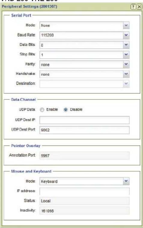
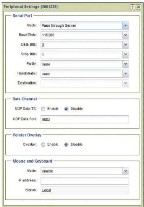
Figure 49. Peripherals Dialog Box
Serial Port
The serial port panel configures the RS-232 port. For a full description of the serial port configuration, including server/client setup, see the VNM 250 User Guide. Default settings are shown in figure 49.
• Mode: — The serial port can operate in one of three modes:
• None: The serial port is not used.
• Pass through Server: The serial port acts as a destination for serial port clients.
• Pass through Client: The serial port can connect to serial ports on other devices
A point to point link can be established by setting the serial port of one VN-Matrix device to Pass-through Server mode and a second device to Pass-through Client mode. The destination of the second device is set to the pass-through port on the first (server) device.
A server can accept multiple client connections. Under these conditions the data input by the server serial port is duplicated to all connected clients. The data received from the clients is multiplexed (in order of arrival) and output through the server serial port.
- RS-232 Settings: Basic configuration of the serial port includes baud rate, data bits, stop bits, parity, and handshake.
- Destination: — This option can only be modified with the serial port in client mode. The drop-down list allows a pass-through connection request from each VN-Matrix device in the network, regardless of whether the device is currently configured as a server.
Data Channel
The data channel panel configures the UDP data stream.
- UDP Data Tx (encoder) — Enables or disables UDP data transport through the dataport.
- UDP Data Port (encoder) — The port number to receive UDP traffic on. This setting must match the port number defined by the external device or system that generates the UDP data.
- UDP Data RX (decoder) — Enables or disables the UDP data.
- UDP Dest IP (decoder) — The IP Address of the external device or system that receives UDP traffic. UNICAST or MULTICAST addresses are valid.
- UDP Dest Port (decoder) — This is the port number used by the (external) device or system to receive the UDP data.
Pointer Overlay
• Overlay (encoder) — Enable the overlay pointer on the local loop-through display.
- Annotation Port (decoder) — Read-only value of the annotation port number.
Mouse and Keyboard
• Mode: — Device specific.
-
Encoder: Enabled, allows mouse and keyboard forwarding.
• Decoder: The control has four options; -
Disable: The decoder does not forward mouse and keyboard information.
- Keyboard: The decoder forwards mouse and keyboard information.
- Keyboard + keepalive: the link is automatically established if broken.
- Force: Mouse and keyboard forwarding + keepalive is permanently enabled.
- IP Address: —
- Encoder: Not Required.
- Decoder: Used to specify the IP address of the target encoder when the transport is multicast or when the encoder exists on a different controller domain.
NOTE: Leading zeros are not allowed.
• Status: — Read-only, is the current status of the link
- Encoder: Disabled, local, or remote keyboard and mouse is displayed.
- Decoder: Disabled, local, or forwarding is displayed. In case of a connection error, a reason is shown in brackets.
- Inactivity: — Read-only (decoder only). Displays the number of seconds since the mouse or keyboard reported a change.
License Menu
Click License to open the Device License Management dialog box. This dialog displays enabled features for the selected unit and enables optional features (see figure 50).

Figure 50. VND 250 (Left) and VNE 250 (Right) License Menu
NOTE: The Licensed Features panel and Current Structure panel fields are read-only (cannot be edited).
Licensed Features panel
The Licensed Features panel details the features currently enabled on the device.
• Video — Indicates the input signal format type.
• Audio — Indicates the number of supported audio channels.
• Video Scaler (VND 250 only) — Indicates whether video scaling is enabled or disabled.
- Whiteboard — Indicates whether whiteboard data streaming is enabled or disabled.
• Data — Indicates whether data streaming is enabled or disabled.
Current Structure panel
The Current Structure panel details the current structure code and its corresponding checksum. These are read-only (non-changeable) fields.
- Structure — Shows the current feature set of the selected device. The values in this code correspond to the active features displayed in the Licensed Features panel, above.
- Checksum — Shows the checksum value used to enable the structure code.
Upgrade Menu
Click Upgrade to open the Upgrade Device Firmware dialog box used to upgrade the firmware (see Upgrade Menu (2xx and 3xx Devices) on page 58).
ATTENTION:
This menu contains four selections for the VND 250 and three for the VNE 250 (see figure 51).
• Real-time Bandwidth Monitor (VND 250)
- Delete Device
- OSD Identifier Editor
- Send HLI Command

Figure 51. VNM 250 Misc Menu
Real-time Bandwidth Monitor (VND 250)
Select the real-time bandwidth monitor to open a new dialog box that monitors the bandwidth (measured in Mbps) used by the selected device or devices (see figure 52).

line
| Time | Bandwidth (Mbps) | | ---- | ---------------- | | 0 | 0 | | 10 | 75 | | 20 | 75 | | 30 | 75 | | 40 | 75 | | 50 | 75 | | 60 | 75 | | 70 | 75 | | 80 | 75 | | 90 | 75 | | 100 | 75 | | 110 | 75 | | 120 | 75 | | 130 | 75 | | 140 | 75 | | 150 | 75 | | 160 | 75 | | 170 | 75 | | 180 | 75 | | 190 | 75 | | 200 | 75 | | 210 | 75 | | 220 | 75 | | 230 | 75 | | 240 | 75 | | 250 | 75 | | 260 | 75 | | 270 | 75 | | 280 | 75 | | 290 | 75 | | 300 | 75 |Figure 52. Bandwidth Monitor
NOTE: Bandwidth data is displayed only for decoder devices. A graph is displayed for an encoder, but the data always shows 0 Kbps.
Delete Device
Select this option to delete the selected device or devices.
NOTES:
- Be certain the appropriate devices are selected when using this menu option. The selected devices are deleted right away; no notification or warning is given when the option is selected.
- A device can only be deleted when it is offline. Active devices can not be removed from the device list.
OSD Identifier Editor
Select this option to customize the appearance of the on-screen display for the selected device or devices (see figure 53).
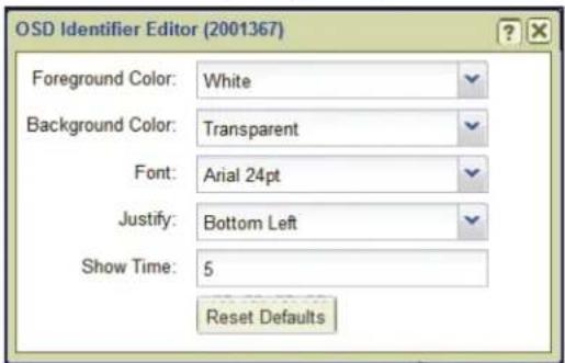
Figure 53. VNM 250 OSD Identifier Editor
• Foreground Color — This drop-down list selects the color of the text box font.
• Background Color — This drop-down list selects the text box background color.
- Font — This drop-down list selects the type of font used in the text block.
- Justify — This drop-down list places the text block in one of nine fixed positions.
• Show Time — Sets the length of time (in seconds) the name of the source device is visible after a connection is made. A value of keeps the name visible indefinitely.
NOTE: This control option only functions when the Identify Source check box is selected in the Configure menu (see VNM 250 Configuration on page 64).
Send HLI Command
Selecting this option opens a dialog box used to send High Level Interface (HLI) command strings to VN-Matrix devices (see figure 54).
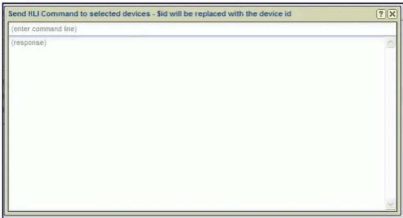
Figure 54. HLI Command Window
To send a command, click in the (enter command line) text field, type the command, and press
NOTE: The response is returned in the response area of the dialog box.
Example HLI commands and information on how to use them are available in System Control on page 175.
Recorder Configuration
This section details options available in the Actions menu bar located at the bottom of the devices page. The options associated with recorders are listed below (see figure 55). The first action bar configuration displays when a recorder is selected. The next bar is available only on the sub-channels of a recorder device. Each sub-channel can be used to record video, audio, and data from an associated VN-Matrix encoder. Click an action button to configure the selected recorder.
VN-Matrix Recorder
| Actions: | Info | Recorder | Configure | License | Upgrade | Misc▼ | Group▼ |
| VN-Matrix Recorder Sub-channel | |||||||
| Actions: | Info | Recorder | License | Misc▼ | Group▼ | ||
Figure 55. Actions Bar Menu, VN-Matrix Recorders
Info Menu
Click Info to open the Device Information dialog box. The box displays read-only information for the selected recorder or sub-channel. The display is the same for the VNR 100 and VNM Recorder (see figure 56).

Figure 56. VN-Matrix Recorders, Device Information
Recorder Menu
Click Recorder to open the Recording Browser dialog box. This box displays recorded files for the selected recorder and recorder sub-channels.
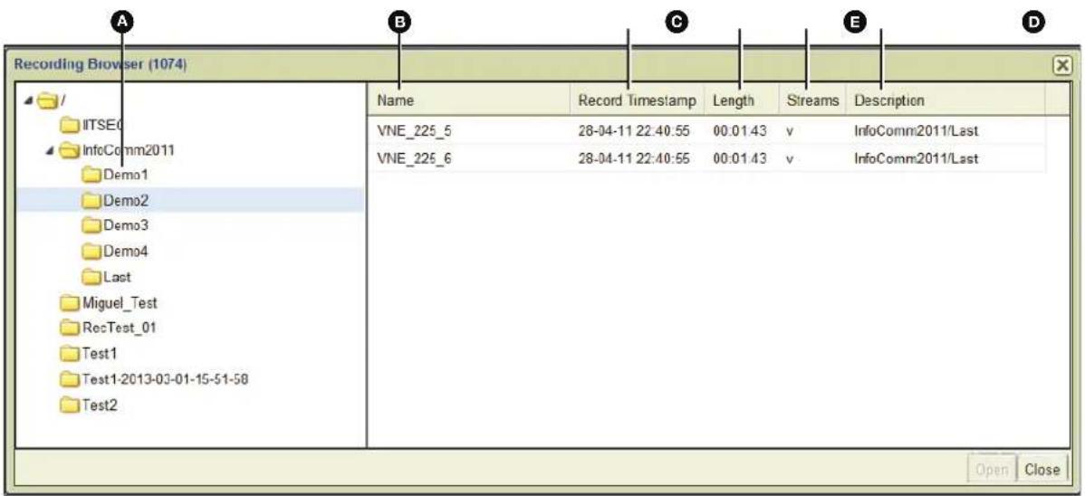
Figure 57. VN-Matrix Recorders, Recording Browser
The user can select a recording from the default location or navigate to another location on the hard drive. The browser provides information on each recording, allowing a user to manage the recordings on the selected device (see File Management Overview on page 111).
The menu items are:
A Directory Tree – The directory structure of the recorder. The tree functions like a standard Windows directory structure.
B Name – The name of each channel in the recording. If a name is not set by the user, the default name of the file is the device ID of the connected encoder.
Record Timestamp – The date and time a recording is created.
D Length – The duration of the recording in hours, minutes, and seconds (HH:MM:SS).
E Streams – The stream types included in the recording; v=video, a=audio, and d=data.
F Description – A text string entered by the user when the recording is created.
Configure Menu
Click Configure to open the Configure Device Settings dialog box used to change the device name or to configure up to three user parameters for the recorder. The dialog box is the same for the VNM Recorder and the VNR 100.

Figure 58. Recorder Configure Dialog Box
Device Setup Panel
- Device Name: — Enter a user defined name for the VN-Matrix Recorder. This is the name that appears in the device list. The name can be letters, numbers, and the underscore character. Spaces are not allowed.
- User Parameters: — Up to three user parameters can be entered in these three fields to customize the operation of the recorder.
Networking Panel
- Multicast TTL: — Specifies the number of router hops multicast traffic can make between routed domains.
License Menu
Click License to open the Device License Management dialog box. This dialog provides information about the recorder features licensed for use on the VN-Matrix system. The information is read-only, shown for reference.

Figure 59. Device License Dialog Box, Recorders
Licensed Features
The Licensed Features panel is not functional at this time.
Current Structure
• Structure — This field details the current structure key for the recorder.
- Checksum — This field details the current checksum for the recorder.
Change Device Structure
The Change Device Structure panel is not functional at this time.
VNS 104 Software Decoder Configuration
The VNS 104 Multi-stream Decoding Software decodes one or four video streams and one stereo audio stream from VNE 225/250 real-time encoders and VN-Matrix Recorder playback channels. It operates on a Windows PC and is managed from the VN-Matrix Enterprise Controller. Before you can view content, ensure the VNM Enterprise Controller is properly licensed with the VNS 104 option and checksum (provided by Extron). Once the Controller license has been updated, the VNS 104 Multi-stream Software Decoder can be selected and configured.
The VNS 104 appears in the devices list as five separate icons, one for the root and one for the each of the decode windows. Each decode window appends the device ID with a number from 1 to 4 (see figure 60).
NOTE: The position of the highlighted display in the VNS 104 icon (☐) is the screen position target for the associated video stream (see figure 60).
| ✓ | ● | VS | 21212121 | VNS104 | 10.13.3.71 | 10.90.0.43 | VNS 104 | ver1.0.0 |
| ● | 21212121:1 | VNS104:1 | 10.13.3.71 | 10.90.0.43 | VNS 104 | ver1.0.0 | ||
| ● | 21212121:2 | VNS104:2 | 10.13.3.71 | 10.90.0.43 | VNS 104 | ver1.0.0 | ||
| ● | 21212121:3 | VNS104:3 | 10.13.3.71 | 10.90.0.43 | VNS 104 | ver1.0.0 | ||
| ● | 21212121:4 | VNS104:4 | 10.13.3.71 | 10.90.0.43 | VNS 104 | ver1.0.0 |
Figure 60. Devices Tab, VNS 104
Actions Menu Bar
Action bar menu items change when switching between the main VNS 104 root icon and the individual decode windows. The Actions menu bar for the main device contains information and configuration options common to all four decode windows. Selecting an action opens a dialog box to configure the individual device.

Figure 61. VNS 104 Action Bar, Main Menu
Info Menu
Click Info to open the Device Information dialog box. There are no configuration settings, only information about the connected VNS 104 device.

Figure 62. VNS 104 Root Device - Device Information
The fields are:
• Device ID – Displays the device ID of the connected VNS 104.
• Device Name – Displays the name of the connected VNS 104.
- IP Address – The IP address of the connected VNS 104 device.
- Device Status – Displays Active when there is a VNS 104 connected, or No Device if a VNS 104 is not detected. When the device is active, the Link Status indicates the quality of the management link.
- Link Status – Displays Good when an active VNS 104 device is connected with little or no management packet loss; Fair when a small amount of packet loss is detected; and Poor for a bad link. When the Link Status is Poor, ensure the link has sufficient bandwidth to carry the data.
Connections Menu
Click Connections to open the Connections dialog box. This box contains general information for the connected VNS 104 device showing the active stream source for each of the four connections.
| Connections | ||
| Video | Audio | |
| Description id 720202.0.0 Source 239.152.1.46:9600 Destination 239.192.1.46:9600 Locale ext Slot -1 | ||
| Description id 620032.0.0 Source 239.192.1.43:8006 Destination 239.192.1.43:8006 Locale ext Slot -1 | ||
| Description id 720197.0.0 Source 239.152.1.29:9574 Destination 239.192.1.29:9574 Locale ext Slot -1 | ||
| Description id 1021158.0.0 Source 239.152.1.42:9600 Destination 239.192.1.42:9600 Locale ext Slot -1 | ||
| Description id 61_Rack_Del.audioPort0 620032.A0.0 Source 239.192.0.43:8008 Destination 239.192.0.43:8008 Locale ext Slot -1 | ||
Figure 63. VNS 104 Root Device - Connections
The Connections dialog box includes:
- Description – Displays the name of the stream source device.
- ID – Displays the device ID of the stream source device.
- Source – For unicast transports, displays the IP address and port number of the stream source device.
- Destination – Displays the IP address and port number of the device receiving the stream.
- Locale – This field displays loc when the data streaming between the source and display are controlled by the same controller (loc). This field displays ext if the data stream has been exported across two different controllers or if the transport protocol is multicast RTP.
- Slot – This field displays information depending on the type of transport protocol in use.
- Using the unicast RTP transport protocol, this field displays the stream number. Four streams are available numbered 0, 1, 2, and 3.
- Using the multicast RTP transport protocol, this field displays ∅ for a source and -1 for a display.
Configure Menu
Click Configure to open the Configure Device Settings dialog box. This box contains general information for the connected VNS 104 device showing the active stream source for each of the four connections.
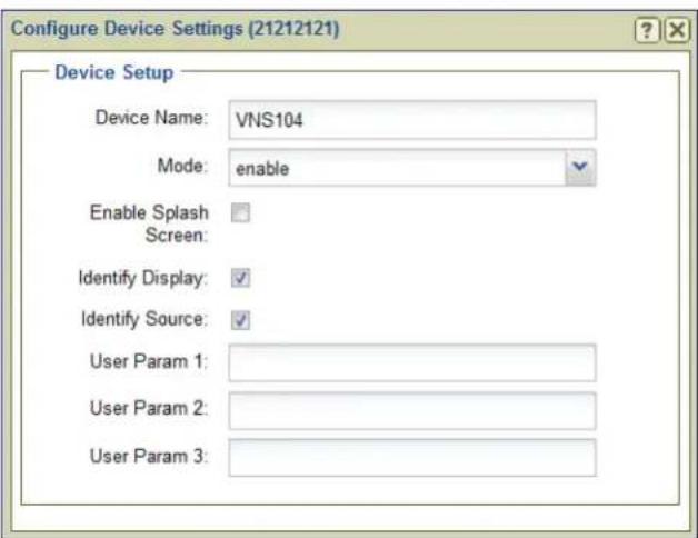
Figure 64. VNS 104 Root Device - Actions Bar, Configure Device Settings
This dialog box contains the following settings:
- Device Name: – This field is used to enter a user defined name for the device. The name appears in the device list and can be letters, numbers, and the underscore character. Spaces and other characters are not allowed.
-
Mode: – Drop-down list selects the operation of the VNS 104. Selections are:
-
Enable – Enables normal decoding of assigned streams.
- Disable – Disables decoding. Displays a splash screen (if enabled), or a black screen.
- Standby – Disables decoding and displays a black screen.
-
Test – Disables decoding and displays a splash screen (if enabled), or a black screen.
-
Enable Splash Screen: – Enables the display of a splash screen when the display device detects a break in the input data stream or a source stream is not assigned. When this check box is not selected, a black screen is displayed when a source stream is not present or when the display device detects a break in the input data stream. See the VNS 104 User Guide for instructions on how to install and use a custom splash screen.
- Identify Display: – Overlays the device name on the decode window or windows.
- Identify Source: – Overlays the source name on the decode window or windows. If a source is not selected for the window, "No Stream Selected" is displayed.
- User Parameters 1-3: – Up to three user parameters can be entered in these three fields to customize the operation of the VNS 104.
Audio Menu
Click Audio to open the Configure Audio Settings dialog box. Only one of the connected video streams can have its audio selected for decode. The audio stream is assigned in the preset manager device attributes control. This dialog sets the level for that stream and also allows it to be muted.

Figure 65. Root Device - Audio Settings Dialog Box
The audio output configuration dialog box provides the following settings:
- Mute Output: – Place a check mark in the box to mute the audio decode stream.
• Volume Level: – Adjust the audio level from -70 to +12. Default is 4.
VNS 104 Misc Menu
The miscellaneous menu provides the following selections:
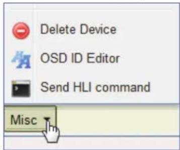
Figure 66. Actions Bar - VNS 104 Root, Misc
- Delete Device: – Deletes the VNS 104 device from the Enterprise Controller Devices list.
NOTES:
- Be certain the appropriate devices are selected when using this menu option. The selected devices are deleted right away; no notification or warning dialog box appears when the option is selected.
-
A device can only be deleted when it is offline. Active devices can not be removed from the device list.
-
Send HLI command: – Sends an HLI command to the selected device.
- VNS 104 OSD ID Editor – Customize the format and placement of the display text entered in the configuration menu (see Configure Menu on page 85).

Figure 67. OSD ID Editor, VNS 104 Shown
The OSD ID editor provides the following:
- Foreground Color: – Sets text color from a list of 11 colors and shades (or transparent).
- Background Color: – Sets background color from a list of 11 colors and shades (or transparent).
- Font – Sets the font and font size from a list.
- Justify: – Sets the position of the text window from a list of nine locations.
- Show Time: – Sets the time (in seconds) the text remains on-screen. ∅ leaves the text onscreen permanently.
NOTE: These settings are applied globally to all VNS 104 decode windows.
VNS 104 Decode Windows
When the streams for each of the four displays are assigned using the Preset Manager (see Preset Manager Page on page 93), select an individual stream to view information specific to that stream and also allow the stream to be customized for the preset.
VNS 104 Decode Windows

Figure 68. VNS 104 Action Bar, Single Stream Menu
Info
The Information dialog menu is the same as the main VNS 104 root device (see Info Menu on page 84).
VNS 104 Display Format
Click the Format button to open the Display Format dialog box. Each decode window provides a dialog box that allows several ways to customize the display of each stream.
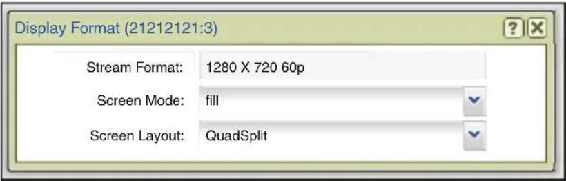
Figure 69. VNS 104 Display Format (One of Four Streams)
In this dialog box the following items are shown:
- Stream Format (read-only) – Displays the format of the assigned stream.
- Screen Mode – Selects from the three screen modes; Fill, follow, or unity (see the VNS 104 User Guide for details on how these screen modes appear on a VNS 104 display).
-
Screen Layout – Select Full screen or QuadSplit screen layouts.
-
Full Screen: The selected decode window is displayed full screen. Only one decode window can be set to full screen. The other decode windows are no longer visible. The decode window last set becomes the active full screen window.
- Quadsplit: The VNS 104 is configured as four decode windows. Each decode window is positioned as part of a 2x2 array.
Using either layout, streams are assigned to decode windows using the Preset manager control or the Switcher page (see Device Attributes – VNS 104 Software Decoder: Decode Window on page 106 and About the Switcher Page on page 89).
NOTES:
- Settings made here are intended to configure the VNS 104 when the VNM Enterprise Controller Switcher page is used.
- Screen Mode and Screen Layout configuration settings are also available in the Preset manager device attributes control for the VNS 104.
- The settings operate on a last takes precedence basis. Modifications to the settings made in either the device list page or preset manager page overwrite previous settings.
About the Switcher Page
The Switcher page assigns encoders (sources) to decoders (displays). This allows the user to control streaming throughout the entire system using a single page. Use the following procedure to configure the Switcher page.
- Click switcher (see figure 70, ①) to open the Switcher page (see Accessing the Web-based User Interface on page 11 for information on how to login).

A new window opens.
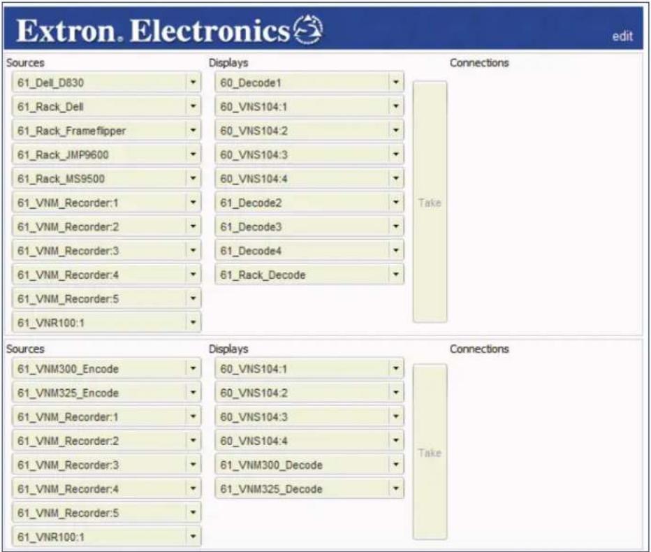
Figure 70. Switcher Window
NOTES:
- In the Switcher screen, VN-Matrix 2xx series devices appear in the upper part of the screen and VN-Matrix 3xx devices appear below. VNS 104 devices and recorders can appear in either.
-
If a VNS 104 is in full screen mode, only a single channel is available for switching. The other three channels are still listed, but are dimmed.
-
In the Sources column, click an encoder (source) (see figure 71, ②).
The selected box darkens.
- In the Displays column, click a decoder (display) (③).
The selected box darkens.
- Click Take ( ④).
A connection is created between the selected encoder (source) and decoder (display).
• Figure 71 shows that the JMP9600 Source is streaming media to Rack_Decode.
- Also, the VN-Matrix 300 source, VNM300_Encode, is streamed to the display, VNM300_Decode (both highlighted in figure 71) when Take is pressed.

Figure 71. Switcher Window "Take"
- Repeat this procedure to create other connections as necessary.
NOTES:
- To remove a connection, select a connection from the Connections column and click Break Connection from the drop-down list.
- To break all connections, select any connection and click Break All Connections.
- Selecting Break All Connections immediately disconnects all devices. No other warning is given.

- If audio data is present within the stream, click on the edit link located at the top right of the Switcher page and select the Switch audio with video (1) option. This keeps the audio and video together when creating connections.

Select Edit Hidden Devices (see next page) to display a pop-up that allows the user to hide any devices on the Switcher page.
Hidden Devices
When there are too many devices on the screen, management becomes difficult. The switcher provides a way to hide unused or rarely used devices.
There are two ways to set and recover hidden devices:
- Click the drop-down button on any source or display device and select Hide Device (①).

- To display the Edit hidden devices menu:
- Click the drop-down button from a source or display device and choose Edit hidden devices (2). -Or-
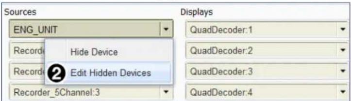
- Click Edit > Edit hidden devices (③) on the main switcher menu.
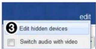
Both step 2 options open the Edit Hidden Devices menu (see right). The menu displays a list of all connected devices whether hidden, or not.
A checkmark in the box indicates the device is hidden. To display the device, uncheck the box. If you want to hide a device or series of devices, place a check mark in each device box.

Preset Manager
This section provides instructions to connect, disconnect, and operate VN-Matrix Devices using the Preset Manager.
Sections include:
- Presets Overview
- Preset Manager Page
- Preset List
• Matrix Devices List - Preset Design Panel
• Device Attributes
• Recorder Directory and File Management - Creating Presets
- Selecting a File for Playback
• Chase-Play Feature (VNR 100 Only)
Presets Overview
Presets can quickly configure and connect devices to operate as a system and fall into three types:
- Switching presets (encoders and decoders only) – Connect an input device (encoder) to an output device (decoder).
- Recording presets (encoders and recorders only) – Connect input devices to the inputs (Record) of the recorder in order to record the connected stream.
- Player presets (players and decoders only) – Connect recorder outputs (Play) to stream previously recorded programs to an output device.
NOTE: The current settings for a device are reflected in the dialog boxes whenever they are accessed in the Device List page, Actions bar.
- Configuration changes made on the Preset Manager page using Device Attributes are applied only when the preset is launched.
• Changes made to a device on the Device List page are applied immediately.
Preset Manager Page
The Preset Manager page enables connection of system devices from the device list for use in the VN-Matrix system. It allows users to create, save, and recall simple or complex system configurations using drag and drop rules under the following guidelines:
- A preset can contain a mix of VNM device types.
NOTE: Some device combinations are not allowed (see Preset Design - Connection Rules on page 97).
- A preset can have a set of attributes that define the mode and configuration parameters of devices in that preset.
• A preset can be named and saved for easy recall. - A preset can be recalled by name using HLI commands.
- Presets are non-exclusive. The recall of one preset does not affect other devices in the VNM system that are not part of that preset.

Figure 72. Preset Manager Page
The preset manager page is divided into four panels:
① Preset List
② Matrix Devices list
③ The Preset: Design workspace
④ Device Attributes
In addition, there are two toolbars:
⑤ To create, launch, stop, copy, rename, or delete a selected preset, a toolbar is located at the bottom of the Preset List panel (1).
⑥ When a new preset is configured or an existing preset modified, it is saved using the toolbar at the bottom of the Preset: Design workspace (③).
Preset List
The Preset List panel (see figure 72, ① on the previous page) provides management and control of the system presets from the preset list toolbar and provides a way to quickly reconfigure devices.
System presets configure and connect groups of VN-Matrix devices for a specific task. They are built using devices in the Matrix Devices list (2). Once defined in the Preset Design workspace (3), presets are saved (6) to the Preset List for use at a later time.
Each preset can contain a mix of matrix devices that includes encoders, decoders, codecs, and recorders. Controls to manage presets are provided at the bottom of the preset list box (5).
All saved presets are displayed in the Preset List workspace, listed in alpha-numeric order. If the list of presets is too long to display within the area, a scroll bar is displayed on the right side of the window pane.
NOTE: Multiple presets can be active, however, the last preset launched takes precedence when connections conflict with other active presets.
Preset List Controls
A toolbar at the bottom of the Preset List workspace provides preset creation and control (5). It is not possible to select multiple presets.
New
Select New to create a preset. When selected, it clears any previously loaded preset from the preset design area (see Preset Design Panel on page 97).
Note: Preset names must not include spaces or non alphanumeric characters such as / *, % ! " £ \$ % ^ & * ()@\~#?><. These characters are blocked from use. Underscore (_) and hyphen (-) are permitted.
Launch
Launch configures and connects devices included in the preset.
Click Launch to activate a preset:
-
Select a preset from the list.
-
Click Launch to activate the preset.
Launch is also available by right-clicking on a selected preset in the preset list.
Stop
Stop clears all settings made in a preset when launched, including:
- Connections between encoders or players and decoders or recorders are removed.
- An active recording or playback is stopped.
Copy
Click Copy to copy a previously defined preset and save it as another name. To copy a preset:
- In the Preset List, select the desired preset.
- Click Copy. The Copy Selected Preset dialog box opens.
-
Enter the name for the new preset into the field entry area.
-
Click OK to save the new preset to the Preset List. -Or-
Click Cancel to abandon the copy process.
- The new preset appears in the Preset List.

Note: Preset names must not include spaces or non alphanumeric characters such as /*, % ! " £ \$ % ^ & * ()@\~#?><. These characters are blocked from use. Underscore (_) and hyphen (-) are permitted.
Rename
Rename changes the name of a previously defined preset.
- In the Preset List, select the required preset.
- Click Rename. The Rename Selected Preset dialog box opens.
- Enter the name for the new preset.
-
Click OK to save the new preset to the preset list. -Or-
Click Cancel to abandon the rename process. -
The renamed preset appears in the preset list.

Delete
Delete erases a previously defined preset.
NOTE: Delete does not clear existing connections made by the preset. To clear those connections, first Stop the preset.
Right-click Behavior
Select a preset from the Preset List and
- Refresh: Update the list with the latest status.
- Launch: Activate the selected preset.
- Transport Controls: For a player or recorder preset, displays the Transport Controls dialog.
- Delete: Deletes the currently selected preset.

Matrix Devices List
The available VN-Matrix devices are displayed on the Preset Manager page as a list in the Matrix Devices panel.
- Matrix devices are listed alphabetically by device name. It is not possible to sort or group them.
- Icons that represent each device are the same as the icons on the devices page (see About the Devices Page on page 36).
- The icon that represents VN-Matrix codecs depends on the mode of that device as set by the active preset. To determine the current mode, right-click anywhere inside the Matrix device area and select Refresh.
• Devices assigned to the currently selected preset appear dim in the list. Note the difference between device11212054, not assigned in the selected preset, and device11212060 and also device11212070 below it, which are both assigned. - A question mark in place of the device icon indicates a device that is no longer connected to the system or powered down.
- After the first channel of a 5-channel recorder is added to a preset, all channels default to the same mode; either all recorder channels or all player channels.
- Single channel recorders are listed as one player and one recorder device.
- When the list is too long to display all devices, a scroll bar allows navigation of the list.
• Devices are selected one at a time. It is not possible to select multiple devices from the list.

Preset Design Panel
The workspace in the Preset: design panel is where new system presets are created and details of a selected preset are viewed.
- Whether creating a new or modifying a current preset, devices are dragged from the Matrix Devices list into the design area to create a preset (see Creating Presets on page 113).
- A new preset is saved the first time using the Save As button. After that, updates are saved using Save.
- Changes made to a preset are discarded by clicking Cancel.
- Save As copies a selected preset to a new name.
- Devices are removed from a preset by highlighting the device, then right-clicking and selecting Delete.
- When a preset is selected from the Preset list (see Preset Manager Page on page 93), the design workspace displays the configuration of all devices used in that preset.
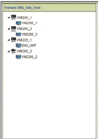
Preset Design – Device Icons
Device icons used in the preset design area are the same as those used on the Device page (see About the Devices Page on page 36).
The icon used in a preset for certain devices depends on the device function in that preset.
- The function of VNM Recorder devices is set only when the channel is placed in a preset. When the first channel is placed, all channels are set to the same mode (recorder or player).
- A codec device can be used as an encoder or decoder. The appropriate icon is shown when the device is placed in the preset.
Preset Design – Connection Rules
Preset connections are subject to connection rules. In the table below, "X" represents connections not allowed or invalid combinations for devices in a preset.
| Connection Rules | Source (Input) Device | ||||
| 2xx Codec 2xx Encoder 3xx | Codec Player | ||||
| Output Device | 2xx Codec Yes | Yes Yes Yes | |||
| 2xx Decoder Yes | Yes Yes Yes Yes | ||||
| 3xx Codec X X | Yes Yes | ||||
| 300 Decoder X X | Yes Yes | ||||
| Recorder Yes | Yes Yes X | ||||
| SW Decoder Yes | Yes Yes Yes Yes | ||||
Additionally, it is not possible to place fixed function devices such as encoder-only or decoder-only devices into an illegal position in the preset.
NOTES:
- In unicast transport mode, the maximum number of connections made to an encoder is four.
- It is not possible to record VNE 250 source material that is HDCP encrypted with the VNR 100 or the VNM 5-Channel recorder.
Device Attributes
When a device is placed in the Preset Design workspace, the Device Attributes panel provides access to preset-specific device settings available to the preset manager. When the device is selected, an appropriate set of attributes for that device populates the device attributes panel. Attributes customize the device for a specific function within that preset and are a subset of the full configuration control set available in the device list view (see About the Devices Page on page 36).
| Device Attributes | |
| Name | VN_Recorder_5CH:1 |
| Directory | /Test1/ |
| File | diff1 |
| Launch Status | Play |
| Repeat | No |
| Time Sync | Yes |
| Start Offset | 00:00:00 |
| Stop Offset | 00:07:02 |
| File Length | 00:07:02 |
Figure 73. Preset Manager, Device Attributes (Player)
The Device Attributes configuration panel populates according to the selected device and its function in the preset. The following information details configuration options available in the attribute panel for each device.
Device Attributes - Codecs
Device attributes change depending on the role of the codec in the preset (see Device Attributes – Encoders, and Device Attributes – Decoders in the following pages).
Device Attributes - Encoders
Only the VNE 250 has attributes configurable by the preset manager. The attribute panel for the other encoder devices only contain a read-only Name field.
| Device Attributes | |
| Name | VNE250_1 |
| Video Input | Auto |
| Program Audio Input | HDMI |
| Return Audio Source | None |
| RS232 Mode | Pass through Client |
| RS232 Server | |
| RS232 Data Tx | Disable |
| UDP Data Tx | Enable |
| UDP Data Port | 9002 |
Figure 74. Device Attributes, VNE 250
• Name — Read-only field for the device name taken from the device list.
• Video Input — A drop-down list to select the input video source. Choices are:
- Auto — This option automatically selects the HDMI input when a digital source is detected.
• HDMI — Selects the HDMI input. - RGB — Selects the RGB input.
- Program Audio Input — A drop-down list to select the program input source. Choices are:
- HDMI — Selects the digital audio from the HDMI input.
- Analog — Selects the analog audio input.
- Disable — Disables both audio inputs.
- Return Audio Source (read-only) — Reports the name of the VND 250 device with return audio enabled in the current preset.
• RS-232 Mode — Drop-down list to select the RS-232 channel mode. Choices are:
- None — the RS232 pass-through port is disabled.
- Pass through Server — Configures the device as a server.
- Pass through Client — Configures the device as a client.
- Data channel — Configures the device to transport RS-232 communications over the data channel.
NOTES:
- In pass-through mode, RS-232 data is bi-directional and can be sent and received between server and client devices. In this mode, RS-232 communications operate independently of device connections. Pass-through communications can not be recorded.
- In data channel mode, RS-232 communications operate over the current connections and are uni-directional, from encoder to decoder. Data channel communications can be recorded.
- RS-232 Server — A drop-down list with the servers currently on the same domain. Only available when Pass through Server is selected in RS-232 mode (see above).
- RS-232 Data Tx — Enable or disable RS-232 data transmission.
- UDP Data Tx — Enable or disable a UDP data transmission port.
- UDP Data Port — Enter the port number that UDP data is received on. This setting must match the port number that is defined by the external device or system that generates the UDP data.
Device Attributes – Decoders
Decoder device attributes differ depending on the selected device (see figure 75).

(a) 200/225 Series
(b) 3xx Series
Figure 75. Device Attributes Panel, Decoders
• Name — Read-only field for the device name taken from the device list.
- Stream settings — The following attributes enable or disable the connection of a specific stream. By default, the video stream is always made when a preset is built. A stream type can only be enabled if it is present in the connection from an encoder or player device.
• VND 200/225 series only
• Audio — Drop-down list enables or disables the audio channels.
- Whiteboard (VND 200/225 only) — Select Yes to decode available whiteboard data from the stream (see License Menu on page 82).
• Data — Select Yes to decode data information from the stream.
• VND 3xx series only
- Ancillary — See Ancillary Audio Panel (VN-Matrix 3xx Only) on page 48.
- Column FEC — See Ancillary Audio Panel (VN-Matrix 3xx Only) on page 48.
- Row FEC — See Ancillary Audio Panel (VN-Matrix 3xx Only) on page 48.
NOTE: The configuration of individual streams is made on the appropriate device in the device list page. For example, the video compression settings or the audio format for an encoder are set on the device list page.
Device Attributes - VND 250 Decoder
The VND 250 decoder has an extended set of device attributes.
| Device Attributes | |
| Name | VND250_1 |
| Output Format | 1024 x 768 60p GTF |
| Scale Mode | Fill |
| Audio Stream | None |
| Program Audio Source | None |
| Program Audio Output | HDMI |
| RS232 Mode | Pass through Client |
| RS232 Server | VND300_2 |
| Data Stream | Yes |
| UDP Data Rx | Enable |
| UDP Dest IP | |
| UDP Dest Port | 9002 |
| Annotation | No |
Figure 76. Device Attributes Panel, VND 250
- Name — Read-only field for the device name, taken from the device list.
• Output Format — Drop-down list of available output resolutions. Choices are:
• Auto — Output format is the same as the input source (stream) format.
- Monitor — Output format is set to the preferred mode (EDID) of the display. If necessary, scaling is applied.
- Fixed — Output format is selected from a drop-down of available resolutions. If necessary, scaling is applied.
- Scale Mode — Drop-down list available when the Output Format is Monitor or Fixed. Choices are:
- Fill — The decoded image is scaled to the selected output format. Aspect ratio is not maintained.
- Follow — The decoded image is scaled to the selected output format. Aspect ratio is maintained.
• Audio Stream — Drop-down list with the following choices:
- None — Mutes the audio streams.
- Program — Enables the decoding of program audio.
- Program plus Return — Enables the decoding of program audio and return path audio.
• Program Audio Source — Drop-down list of the other VNE 250 devices in the preset.
- None — Default. Selects audio from the currently connected stream.
• {List} — Selects an audio source from a list of VNE 250 devices in the preset.
- Program Audio Output— Selects the required output for the program audio.
- HDMI — Select to enable the HDMI audio output.
- Analog — Select to enable the analog audio output.
- Both — Selects both the analog and digital audio outputs.
- Disable — Mutes all audio output.
- RS-232 Mode — Drop-down list to select the RS-232 channel mode.
- None — the RS-232 pass-through port is disabled.
- Pass through Server — Configures the device as a server.
- Pass through Client — Configures the device as a client.
- Data Channel — Configures the device to transport RS-232 communications over the data channel.
NOTES:
- In pass-through mode, RS-232 data is bi-directional and can be sent and received between server and client devices. In this mode, RS-232 communications operate independently of device connections. Pass-through communications can not be recorded.
- In data channel mode, RS-232 communications operate over the current connections and are uni-directional, from encoder to decoder. Data channel communications can be recorded.
- RS-232 Server — When RS-232 mode is set to Pass through Client provides a drop-down list of available servers on the system.
• Data Stream — Select Yes to enable the data stream, No to disable.
- UDP Data Rx — Select Enable to receive UDP data from the system. When enabled, the UDP Dest IP and UDP Dest Port selections are listed below.
- UDP Dest IP — The IP address of the external device or system that receives UDP traffic. UNICAST or MULTICAST addresses are valid.
- UDP Dest Port — The port number used by the (external) device or system to receive the UDP data.
- Annotation — Select Yes to enable annotation pointer overlay functions.
NOTES:
- When creating a videowall using presets, VND 250 devices are configured and connections are built using the Preset Manager. Modifying the output format or the scale mode settings of a VND 250 decoder in the Presets Device Attributes panel changes the current configuration of the decoder in the Device List to those set in the Device Attributes panel only when the preset is launched.
- The normal encoder to decoder connection count limit applies.
- Unicast transport supports a maximum of four connections to a single encoder. Note that each unicast connection increases the bit rate by the same amount for each connection. The aggregate bit rate for four unicast connections can not exceed the maximum supported bit rate of 270 Mbps for an encoder.
- Multicast transport supports "one to many" connections allowing for wall sizes of more than four displays.
See the System Config Page on page 28 for additional information on unicast and multicast connections.
Device Attributes – VN-Matrix Recorder: Play Mode
The 5-channel VN-Matrix Recorder in player mode operates with Ch1 set as the primary for all channels (see figure 77, left).
| Device Attributes | |
| Name | Recorder_5Channel:1 |
| Directory | |
| File | |
| Launch Status | Play |
| Repeat | No |
| Time Sync | Yes |
| Start Offset | 00:00:00 |
| Stop Offset | 00:00:00 |
| File Length | 00:00:13 |
| Device Attributes | |
| Name | Recorder_5Channel.2 |
| Directory | |
| File | |
| File Length | 00:00:13 |
Figure 77. Device Attributes, 5-channel Player
The player device attributes for a 5-channel device provide the following functions:
NOTE: The attributes for individual channels 2, 3, 4, and 5 (shown in figure 77, right) are a reduced set of the attributes for Ch1.
- Name — Read-only field displays the device name and selected sub-channel number.
- Directory — Opens the recorder browser for directory level navigation and selection.
- File — Opens the directory listed in the Directory field to enable selection of a single recorded file and displays the filename.
-
Launch Status — Drop-down control to define the start condition of a Play or Record preset.
-
Play (player channel 1 only) — When the preset is launched, playback begins immediately.
- Provision — Delays playback until the appropriate command is sent from the transport bar or from an external control system.
- Repeat — A drop-down control sets a player into loop mode.
- Time Sync — A drop-down control that sets the timing relationship between the channels on multiple devices in a player preset.
- Start Offset — Editable field that sets the start time of a selected file.
- Stop Offset — Editable field that sets the stop time of a selected file.
- File Length — Displays the length of the recording in hh:mm:ss format.
Device Attributes – VN-Matrix Recorder: Record Mode
The 5-channel VN-Matrix Recorder in recorder mode operates with Ch1 set as the primary for all other channels on that device.
| Device Attributos | |
| Name | Recorder_5Channel-1 |
| Directory | /RecTest_01V |
| File | ChaseTST01 |
| Launch Status | Record |
| Description | |
| Audio | No |
| Whiteboard | No |
| Data | No |
Figure 78. Device Attributes, 5-channel Recorder
The recorder device attributes for a 5-channel device provide the following functions:
- Name — Read-only field displays the device name. For the 5-channel recorder, if a sub-channel is selected, this displays the device name and sub-channel number.
- Directory — Type a new directory name directly into an editable field or use a file browser to create and delete directories (see Recorder Directory and File Management on page 107).
- File — An editable field and navigation tree to create and delete files.
-
Launch Status — Drop-down control to define the start condition of the preset.
-
Provision — Places the recorder in pause when the preset is launched. The recording begins only when the record button is clicked on the transport bar.
- Record — When the preset is launched, starts the recording immediately.
• Description — A user defined text field used to describe the recording.
• Audio — Select Yes to enable or No to disable the audio stream.
- Whiteboard — Enable/disable whiteboard (see Recorder Configuration on page 79).
• Data — Enable/disable a data stream (see Recorder Configuration on page 79).
Device Attributes - VNR 100 Player
The VNR 100 single-channel player attributes panel provides the following functionality:
| Device Attributes | |
| Name | VNR100:p |
| Directory | /GFChaseTst/ |
| File | TEST |
| Launch Status | Play |
| Time Sync | Yes |
| Start Offset | 00:00:00 |
| Stop Offset | 00:00:00 |
| File Length | 00:00:02 |
Figure 79. Device Attributes, VNR 100 Player
The function of each attribute is the same as the 5-channel player (see Device Attributes - VN-Matrix Recorder: Play Mode on page 103).
NOTE: You cannot set a stop offset in chase-play (live) mode when using a single channel recorder (see Chase-Play Feature (VNR 100 Only) on page 128).
Device Attributes - VNR 100 Recorder
| Device Attributes | |
| Name | VNR100:r |
| Directory | /New_Directory/ |
| File | GDFTST_002 |
| Launch Status | Record |
| Description | Test File |
| Audio | No |
| Whiteboard | No |
| Data | No |
Figure 80. Device Attributes, Single-Channel Recoder
The VNR 100 recorder Device Attributes panel provides the following functionality:
- Name — Read-only field displays the device name.
- Directory — Type a new directory name into this field or use a file browser to create and delete directories.
- File — An editable field and navigation tree to create and delete files.
- Launch Status — Drop-down control to define the start condition of a preset.
- Provision — Places the recorder in pause mode when the preset is launched. The recording begins only when the record button is clicked on the transport bar.
- Record — Starts the recording immediately when the preset is launched.
• Description — A user defined text field to describe the recording.
• Audio — Enables or disables audio recording. - Whiteboard — Enables or disables whiteboard data recording.
• Data — Enables or disables data stream recording.
Device Attributes - VNS 104 Software Decoder: Decode Window
| Device Attributes | |
| Name | VNS104:1 |
| Audio | No |
| Mute Audio | No |
| Audio Volume | 4 |
| Screen Mode | Fill |
| Screen Layout | QuadSplit |
Figure 81. Device Attributes, VNS 104
Each VNS 104 decode window has the following attributes (see figure 81):
- Name — Read-only field for the device name.
- Audio — Drop-down list enables (Yes) or disables (No) connection of specific stream types within a decoder channel.
- Mute Audio — Mutes the audio stream.
• Audio Volume — Sets the volume level of the audio stream. - Screen Mode — Select from three screen modes; Fill, Follow, or Unity (see the VNS 104 User Guide for more details on how these screen modes appear on a connected display).
- Screen Layout — Select between Full screen or QuadSplit screen layouts. In full screen layout, the selected channel is the only one available to the display (see VNS 104 Software Decoder Configuration on page 83).
Recorder Directory and File Management
VN-Matrix recorders can be used as a source (player) or display (recorder). The following section describes the recorder directory and file structure and rules to assist in their management.
Directory Management Overview
A recording can be made on single or multiple devices (recorders). A recording contains all files required to recreate the original stream from an encoder in a set. The set can consist of audio, video, and data file types. Each recording set is stored in a unique directory.
• Each directory can hold only the files for a single recording.
- Directories must have a unique name, duplicates are not allowed.
A new directory can be created in two ways. The same methods are used on both the single and 5 -channel devices.
NOTE: Directory names must not include spaces or non alphanumeric characters such as / *, % ! " £ \$ % ^ & * ()@\~#?><. These characters are blocked from use. Underscore (_) and hyphen (-) are permitted.
Create Directory – Directory browser method (preferred)
To create a new directory using the navigation tree:
- Create a preset with an encoder and recorder (see Recorder Presets on page 119).
- Select a recorder (channel) in the Preset Design workspace.
- Click anywhere inside the Directory field of the Device Attributes panel, then select the drop-down box on the right hand side (see figure 82, 1).

Figure 82. Select Directory Drop-down Box
The Recording Browser dialog box opens.
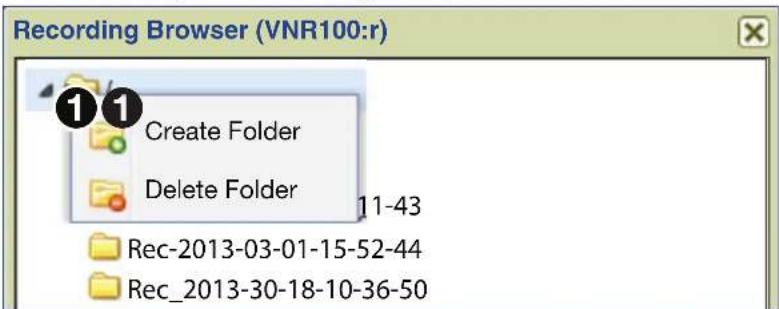
Figure 83. Recording Browser Window, Create Folder
- Select the root folder,
on the folder (see figure 83, ①), then click Create Folder.
The Create Folder dialog box opens.
- Enter the directory name and click OK.
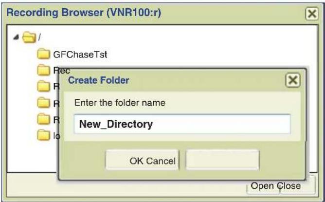
Figure 84. Create Directory, Enter Name
NOTE: Using this method, the directory is created and displayed in the directory list immediately.
The new directory is created and the Recording Browser dialog box displays all directories, including the new one. The browser remains open.
- Select the new directory, and click Open to continue (see figure 85, ①).
NOTE: Select Close to cancel the process (the new folder remains).

Figure 85. Recording Browser, Select and Open Directory
- A dialog box opens. Select Yes (see figure 86, ①) to automatically create the same directory on other recorder devices in the preset, or No to continue.
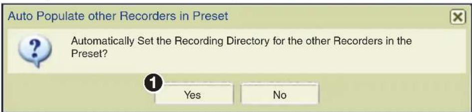
Figure 86. Recording Browser, Auto Populate Other Recorders
NOTE: If multiple recorder devices (single or 5-channel) are in the preset, using the same directory simplifies file selection for replay.
Create Directory – Direct entry method (advanced)
To create a directory using direct entry:
- Create a preset with an encoder and recorder (see Recorder Presets on page 119).
- Select a recorder (channel) in the Preset Design workspace.
- In the Device Attribute panel, click in the Directory row and enter the new directory name in the field.
A red marker indicates a change in the device attributes (see figure 87).
| Device Attributes | |
| Name | VNR100:r |
| Directory | New_Directory |
| File | |
| Launch Status | Record |
| Description | |
| Audio | No |
| Whiteboard | No |
| Data | No |
Figure 87. Device Attributes - Create Directory (Advanced)
NOTE: Using this method, the new directory appears in the browser directory listing only after the preset is launched.
- Save the preset. The red marker clears when the preset is saved.
NOTE: It is only necessary to set the directory name on one channel in a 5-channel device. Although it is possible to enter different directory names in the other four channels, the name used for the directory when the preset is launched is the directory name last entered. Therefore, all channels use the directory name entered last and ignore the previous entries.
Duplicate Directory Naming
If a recorder preset is built (or copied) using an existing directory name, or if the same preset is launched more than once without changing the name of the directory, a new directory name is automatically created. The first time a recording is launched, the previously entered directory name is created (see figure 88).

Figure 88. Duplicate Directory Naming
When the same preset is launched a second time, a new directory name is created using the original directory name appended with a time and date stamp (see figure 89).

Figure 89. Duplicate Directory Naming, New Recording
Each directory contains only the files from a single recording.
Delete Directory - Recording Browser
Directories are deleted using the Recording Browser.

Figure 90. Delete Directory
All files in the directory are deleted. A warning is given to confirm the deletion.
NOTE: The root directory can not be deleted.
File Management Overview
The recorder allows creation of both directories and files while the player can only select directories and files after they are created by the recorder.
Filename
By default, the name of the encoding device is used as the name of the recorder file. The default name is changed by entering a new name in the Device Attributes File field.
Creating a File
A file is created when a recording begins. If the file field is blank when the recording starts (see figure 91), the device name of the encoder is used as the filename.
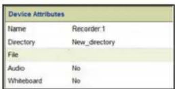
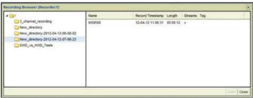
Figure 91. Create a File
NOTE: The filename field in the Device Attributes panel remains blank.
If a specific filename is desired, the name is entered in the File field (see figure 92, ①), which then becomes the name of the file in the recording (②).
NOTE: File names must not include spaces or non alphanumeric characters such as /*, % ! " £ \$ % ^ & * ()@\~#?><. These characters are blocked from use. Underscore (_) and hyphen (-) are permitted.
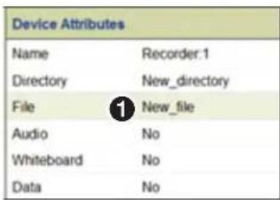

Figure 92. Create a File Using Direct Text Input
Completed Directory Structure
A recording directory contains one set of files for each recorder (channel) in the preset. A file set can contain audio, whiteboard, and other data streams associated with the video file.

Figure 93. Recording Browser, One File per Channel
Deleting a File
Delete a file by highlighting it in the browser,

Figure 94. File Browser, Delete a Channel
NOTE: The browser must be refreshed after a delete.
Player File Management
All files for a single recording are in one directory. In a 5-channel device, the directory can contain up to five sets of files, one for each channel.
In a multi-player system, the same directory must be present on all devices, and each directory must contain the files recorded for that channel.
When selecting a previously recorded file for playback, navigate to the directory using the Recording Browser. When the directory is selected, files in the directory are loaded into all players automatically. It is not necessary to select individual files for each player device.
Creating Presets
Presets are created that configure devices to operate as a system. Once created, presets can be launched with a single button click. The Enterprise Controller then reconfigures and connects the devices in the preset to create the system.
The three preset types are:
- Switching – Connect inputs to outputs. Source devices must always be placed into the design area first. Source devices (codecs, encoders, or players) are dragged from the Matrix Devices list into any blank space in the Preset Design workspace.
- Record – Connect encoders to a record channel, select the stream and stream types to record, and specify the directory and file names. Source devices are always placed first with the desired recording channel dropped on it.
- Play – Connect decoders to a player and view previously recorded material. Players are always placed first followed by the decoder.
Several general rules for the Preset Design workspace are:
- The first device dragged into the design area is positioned vertically on the left hand side of the workspace. Subsequent devices are positioned under the previous one in the order placed.
- Once placed in this column, the space to the right of a source device becomes a connection point for decoders or recorder channels.
- A Codec can be added to a preset regardless of its current mode. When dropped into the design area first, a codec formatted as a decoder reconfigures to an encoder. Similarly, a codec formatted as an encoder, reconfigures to a decoder when dropped onto an encoder.
Create a New Preset
To create a new preset, drag and drop a device onto the Preset panel, then drag an appropriate device onto the first device. In this example, Encode1 is an encoder streaming video to the system. Decode1 is a decoder connected to a display.
To create an encoder to decoder preset:
- Click New (①) at the base of the Preset List panel to create a blank preset (see Preset Manager Page on page 93).

Figure 95. Preset List - New Preset
- Add an encoder to the Preset panel. Click and hold the encoding device (see figure 96, ②).

Figure 96. Preset Workspace, Place a Device
- Drag the device to the upper left corner of the Preset panel (③).
- Drop the device ( ④).
NOTE: Devices dragged into the Preset Design workspace are positioned on the left side in the first open space vertically, and in the order they are placed.
- Add a decoder to the Preset panel. Click on and hold the desired decoder (see figure 97, 1).
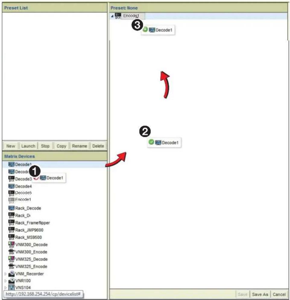
Figure 97. Preset Workspace, Add a Decoder
- Drag the device to the upper left corner of the preset panel (②).
- While holding the decoder, place it on top of the previously placed Encoder1, then release (3).
The preset completes after a moment.
NOTE: Although the user interface shows a connection between the devices, the connection is made only when the preset is launched (see Launch Behavior on page 121).
Saving Presets

Figure 98. Save a Preset
Before saving the preset, configure the decoder using the Device Attributes panel (the encoder has no attributes available).
- Click on the decoder device in the Preset panel (see figure 98, ①) to populate the device attributes (②).
- Configure the attributes of the decoder (②) as needed (see Device Attributes on page 98).
NOTE: A red triangle appears as each attribute is changed to remind you the changes have not been saved. The triangle goes away when the preset is saved.
- When the decoder is configured, click Save As on the Presets panel toolbar (③). The Save As dialog opens.
- Type a name using the standard naming format, then click OK (④).
- The new name appears in the Preset List panel (⑤).
- Click on the preset, then click Launch on the Preset List toolbar to activate the preset (6).
Using the VNS 104 in a Preset
The VNS 104 appears in the Device List as a four channel decoder with four possible connections. In the Preset Design panel, each channel can be connected to the same or to a different encoder or player channel.
- Select New at the base of the Preset List panel to create a blank preset (see figure 99, ①).

Figure 99. Presets, Using the VNS 104
- Drag an encoder from the Device List and drop it onto the Preset design panel.

Figure 100. Presets, Drag and Drop an Encoder
NOTE: Devices dragged into the Preset panel workspace are positioned in the first open space vertically on the left hand side of the design area in the order they are placed.
- Drag one of the four software decoder channels (see figure 101, ①) from the Device List and drop it onto the source device in the Preset panel.

Figure 101. Presets, Drag and Drop the VNS 104
NOTE: Output devices are positioned below and to the right of the source device they are connected to.
- Set output device attributes as required (see Device Attributes on page 98).
- Click Save As and name the preset (see Preset List on page 94).
The connection between the source device and the VNS 104 Software Decoder window is now available.
- Either drop more software channels onto the encoder, or drag more encoders into the Preset panel, then drop additional software decoder channels onto them as required. In this manner, connections are made between inputs (sources) and any or all channels of the VNS 104 Multi-stream Software Decoder.
Recorder Presets
Recorder presets are created similar to switching presets. Place an encoder device into the Preset panel first, followed by a recorder channel or channels. Use the Device Attributes panel of a recorder to create or select a file directory, and select the channels to record.
To Record a Channel
- Create a preset with an encoder source and recorder channel (see figure 102).

Figure 102. Create a Preset
- Select the record channel (see figure 103, ②). The Device Attributes panel populates with the configuration options appropriate for the recorder.
- Create or select a directory (③) for the recording file (see Directory Management Overview on page 107).
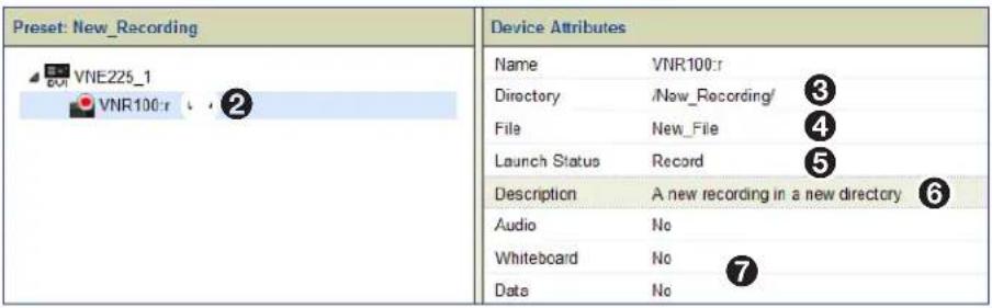
Figure 103. Select the Record Channel
- Enter a filename (④) for the recording (see Recorder Directory and File Management on page 107).
- Set the launch status ( ⑤) (see Launch Behavior on page 121).
- Enter a description, if desired (⑥).
- Select the remaining recording options (audio, whiteboard, and data) as needed (⑦).
- In the Preset panel, click Save (see Saving Presets on page 116).
The record preset is now complete.
- Click Launch in the Preset List panel to begin the recording.
VNE250, HDCP, and Recording
It is not possible to record an HDCP encrypted source, however, this condition is not rules checked in the preset manager (see Preset Design – Connection Rules on page 97). The source content is known only when the preset is launched and the recording starts.
If there is an attempt to record HDCP content, the system behaves as described for other content. However, the recorded file is not created if the content is HDCP encrypted. This condition is not flagged in the user interface.
Player Presets
Player presets are created similar to switching presets. A player channel is placed into the Preset panel first, followed by a decoder or decoders. The player channel attributes include the playback directory, the playback file, set the start and end offset time and synchronization, and select the playback channels.
To Play a Channel
- Create a preset with a player channel and a decoder (see Creating Presets on page 113).

Figure 104. Preset for Playing a Channel
- In the Preset panel, select the player (see figure 104, ①).
The Device Attributes panel populates with the configuration options appropriate for the player (2).
-
Select an existing directory (③) (see Selecting a File for Playback on page 124).
-
Select a filename (④) for playback (see Selecting a File for Playback on page 124).
-
Set the launch status ( ⑤) as desired (see Launch Behavior on page 121).
-
Select playback options (Time Sync, Start Offset, Stop Offset, and File Length) from the remainder of the list (6).
-
In the Preset panel, click Save, then name the preset (see Saving Presets on page 116).
The play preset is now ready.
- Click Launch in the Preset List panel to start playback of the file.
Launch Behavior
Click Launch (see Preset List Controls on page 94) to activate a previously saved preset. Launching a preset causes the configuration of the devices to change according to the device attributes and connections specified in the preset. Until launched, the Preset List defaults each preset to Stop.
In general, presets operate independently of each other. When a preset launches, devices in the preset are configured according to the attributes and connections of the preset regardless of their previous mode and operation. No other devices in the system are affected.
When the same devices are used in multiple presets, device operation is defined by the configuration and connections made in the last preset launched.
Switcher Launch Behavior
When a switching preset is launched, attributes for each device in the preset are changed according to the device attributes saved in the preset (see Device Attributes on page 98). The connections between the devices are then made according to the diagrams in the Preset design workspace (see Preset Design Panel on page 97).
Recorder Launch Behavior
The Launch Status in the Device Attribute panel (see Device Attributes on page 98) is available for presets that contain recorder or player devices. A recorder preset follows the same behavior as a switcher, first changing attributes which include creating recording directories and files, then making connections. The recording action provides a transport bar to monitor operation (see Transport Bar Shortcut on page 127). Playback behavior first selects the location of the playback files, then begins playback according to the launch state selection.
The behavior defines the recorder or player actions when launched, specifically when a new preset uses a device active in another preset. Specific behavior is described in the following tables.
| Player Active Status | ||||
| Playing Recording | (5-Channel Only) | None | ||
| Player Preset | Play Stop | playing the existing file, load and play the new file. | Stop recording the existing file, provision and play the new file. | Provision and play the file per the preset. |
| Provision | Provision the new file, continue playing the current file according to its preset status and wait. | Stop recording the existing file, provision the new file and wait. | Provision the file and wait. | |
| Recorder Active Status | ||||
| Playing (5-Channel Only) | Recording None | |||
| Recorder Preset | Record Stop playing the existing file, provision and record the new file. | Stop recording the existing file. Provision and record the new file. | Provision the new file and start recording. | |
| Provision Stop playing the current file, provision the new file for recording and wait. | Stop recording the current file. Provision the new file, and wait. | Provision the recorder per the preset and wait. | ||
| NOTE: All channels on a 5-channel recorder are automatically set to the same mode (record or play) whether they are present in the active preset or not. | ||||
Transport Dialog Box - Recorder
When a recorder preset is launched (see Preset List Controls on page 94), a transport dialog box displays the recording status and provides control of the recording. Only the most recent preset launch is displayed (see figure 105).
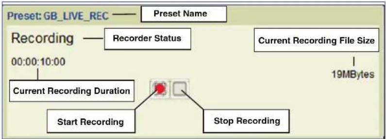
flowchart
graph TD
    A["Preset: GB_LIVE_REC"] --> B["Recording"]
    B --> C["Recorder Status"]
    C --> D["Current Recording File Size"]
    D --> E["19MBytes"]
    B --> F["Current Recording Duration"]
    F --> G["Start Recording"]
    F --> H["Stop Recording"]
Figure 105. Transport Dialog Box-Recorder
When the launch status in the Device Attributes panel is configured to Record, recording begins immediately and the transport dialog monitors the recording (see figure 102). If the launch status is set to Provision, the panel provides manual control of the recording start and stop.
The recorder transport dialog box has the following functionality:
| Status / Action Description Comment | ||
| Preset launched Transport dialog opens. | Recording Status = StoppedRecording duration = 00:00:00:00Filesize = 0 MBytes | |
| Record button (Provision) | Begins recording when pressed. | Same as above. |
| Record button (Record) | Recording starts immediately. | Status = RecordingRecording duration = Displays the current duration (time) of the recording.Filesize = displays the current storage size (MBytes) of the recording. |
| Stop (Provision or Record) | Stops recording. Status = StoppedRecording duration = Displays the duration (time) of the entire recording.Filesize = displays the final storage size (MBytes). | |
| NOTE: It is not possible to record an HDCP encrypted source, however, this condition is not rules checked in the preset manager since the source content is known only when the recording is started.If an attempt to record HDCP content is made, the transport bar behaves as described for all content. However, the recorded file is not created if the content is HDCP encrypted. This condition is not flagged in the user interface. | ||
Transport Dialog Box – Player
When the launch status in Device Attributes is configured to Play, playback begins immediately and the transport dialog box monitors playback. If the launch status is set to Provision, manual control of the playback start and stop is available.
The Player panel also provides the following functionality:

Figure 106. Transport Dialog Box - Player
| Play Transport Control Behavior | ||
| Status / Action Description Comment | ||
| Preset launched Transport dialog box launched. | 1 Status = Stopped2 File duration = File length [time].3 Progress bar = Slider positioned at left hand side.4 Current file time = 00:00:00:006 Shuttle control = Play x1 | |
| Play button (7) | From Stop: Start playing the current file.From Pause: Resume play from the current time. | 1 Status = Playing2 File duration = File length [time].3 Progress bar = Slider moves to the right as the file plays.4 Current file time = Shows running file time.6 Shuttle control = Play x1 |
| Pause button (7) | Pauses the current file (not operative from stop mode). | 1 Status = Paused2 File duration = File length [time].3 Progress bar = Slider stationery.4 Current file time = Current file time.6 Shuttle control = Pause |
| Stop (7) | Stops playback. | 1 Status = Stopped2 File duration = File length [time].3 Progress bar = Slider positioned at left hand side.4 Current file time = 00:00:00:006 Shuttle control = Play x1 |
| Shuttle control (6) | Provide access to x1, x2, x4 and x8 speed control in forward and reverse. | 1 Status = Shows direction and speed.2 File duration = File length [time].3 Progress bar = Tracks the time and direction.4 Current file time = Static at last value.6 Shuttle control = Speed and direction appear above the slider control. |
| Slider control (5) | This slider can be dragged to any point on the progress bar. Forces play x1. | 1 Status = Playing2 File duration = File length [time].3 Progress bar = File time at the slider position.4 Current file time = Current time, incrementing.6 Shuttle control = Play x1 |
| Jog Control (8) | Provides access to 1, 5, 10 and 20 frame steps in both forward and reverse direction.Only active from Pause mode. | 1 Status = Paused2 File duration = File length [time].3 Progress bar = Not updated.4 Current file time =Not updated.6 Shuttle control = Pause |
| NOTE: File time is displayed to the nearest second. | ||
Selecting a File for Playback
To select a file for playback (single or five channel recorder):
- Create a preset with a player and decoder or display (see Creating Presets on page 113).
- Select the player channel in the Preset workspace. The Device Attributes panel populates with the appropriate options.
- Click in the Directory field of the Device Attribute panel, then click the drop-down button at the right hand side of the Directory field (see figure 104, ①).

Figure 107. Device Attributes, Directory Selection
The File Recording browser opens.
- In the browser, click the directory containing the desired file (the directory is highlighted, see figure 108, ①).

Figure 108. Recorder Browser, Directory Browsing
- Click Open (see figure 108, ②).
- A dialog box opens (see figure 109 on the next page).
a. Select Yes to automatically assign the video files to corresponding player channels. If the directory contains five files recorded on a 5-channel recorder, it loads the corresponding files into slots 1 through 5 of the device. It also populates multiple player devices within the preset if they are all part of the same original recording group. The preset is ready to launch.
b. No loads the file only to the device selected in the Preset panel. Proceed to step 7.
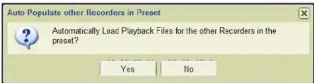
Figure 109. Device Attributes, Load Playback File
NOTE: For multi-channel recordings made on a 5-channel device, it is not possible to select content from different directories (recordings) for replay.
- Click in the File field of the Device Attribute panel (see figure 110, ①), then click on the drop-down button at the right hand side of the File field.
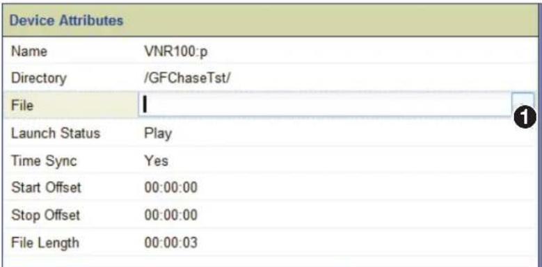
Figure 110. Recorder Device Attributes, File Selection
The browser opens to the directory (see figure 111) with a list of available files.
- Select the desired file (see figure 111, ①).

Figure 111. File Browser, Select File
- Click Open (②).
The recorder is ready to play the selected file (see figure 112).
| Device Attributes | |
| Name | VNR100:p |
| Directory | /GFChaseTst/ |
| File | GFRecTst_01 |
| Launch Status | Play |
| Time Sync | Yes |
| Start Offset | 00:00:00 |
| Stop Offset | 00:00:00 |
| File Length | 00:01:11 |
Figure 112. Device Attributes, Playback File Selected
The remaining device attributes provide several options for playback of the selected file.
Launch Status
The launch status options are:
- Play: When launched, the preset immediately configures the devices in the preset and starts playback of the selected file.
- Provision: When launched, the preset configures the devices for playback to begin, then displays the player transport controls with the player in pause. The Play button must be pressed to initiate playback.
The playback transport panel opens regardless of which launch status is chosen.
Time Sync
The time sync setting maintains the timing relationship between content loaded across multiple devices.
Select Yes (enabled) to play related files made at the same point in time across multiple devices as part of a group.
Select No (disabled) to play unrelated files across multiple devices in a preset.
Setting the start and end times for playback
Start offset is changed to set the starting point for replay in hours, minutes, and seconds. The default value is 00:00:00.
The Stop offset setting is changed to set the end point for replay in hours, minutes, and seconds. The default value is the end of the file.
Adjustment of both settings is limited to within the time of the recorded file.
NOTE: An end time cannot be set for live play mode.
File length
The read-only file length field displays the total play time in hh:mm:ss format.
Transport Bar Shortcut
The transport bar can also be launched by

Figure 113. Right-click Access to Transport Controls
Chase-Play Feature (VNR 100 Only)
The chase-play feature allows a user to view a live recording while the recording is in progress. The live file can be played, paused, or searched from any point in the file as the recording progresses.
Configuration
A recording preset is built and configured in the normal way (see Recorder Presets on page 119). Note the directory and filename given to the recording (see figure 114).
| Preset: RecChaseTst_rec | Device Attributes | |
| VNE300_2 VNR100.r | Name VNR100.r | |
| Directory /GFChaseTst/ | Directory for the live recording. | |
| File Chase_Play_01 | File name of the live recording. | |
| Launch Status Provision | Action when file is launched. | |
| Description Recording for Chase/Play Test | ||
| Ancillary No | ||
| Column FEC No | ||
| Row FEC No | ||
Figure 114. Device Attributes, Recording Preset for Live Recording
A corresponding player preset is built and configured in the normal way using the same directory and filename configured in the recorder preset (see Player Presets on page 120).
| Preset: RecChaseTst_play | Device Attributes | |
| Name | VNR100:p | |
| Directory | /GFChaseTst/ | |
| File | Chase_Play_01 | |
| Launch Status | Provision | |
| Time Sync | Yes | |
| Start Offset | 00:00:00 | |
| Stop Offset | 00:00:00 | |
| File Length | 00:03:41 | |
Figure 115. Device Attributes, Player for Live Recording
NOTE: When selecting the playback filename, a file that is currently recording is flagged with a red record marker in the file browser (see figure 116).
| Name | Record Timestamp | Length | Streams | Description |
| Chase_Play_01 | 06-05-13 09:11:12 | 00:00:16 | v | Recording for Chase/Play Test |
Figure 116. File Browser, Active Recording
To begin chase-play:
- Launch the recorder preset. The transport bar opens with the recorder in pause (see Transport Dialog Box – Recorder on page 122).
- Start the recorder from the transport bar.
- Launch the player preset (see Transport Dialog Box - Recorder on page 122). The transport bar opens with the player in pause.
- The player file transport bar displays the file information for the live recording. Transport control behavior in live flow is shown in the following table.
Features available for playback of live content (chase-play) are the same as those supported for normal playback (see Launch Behavior on page 121).
| Transport Control Behavior - Live Play | ||
| Player Control Function | Comments | |
| Play Starts playing the active recording from any point (time). | The location where replay starts can be set to any time from the file beginning to within one second of the end of the live file. | |
| Pause Pauses the replay at its current time. Live recording continues. | ||
| Stop Stops the replay. | Live recording continues. | |
| Fast forward (shuttle) The content is decoded at the required (faster than real-time) rate in the forward direction. | The speed can be any supported rate. | |
| FAST reverse (shuttle) The content is decoded at the required (faster than real time) rate in the reverse direction. | The speed can be any supported rate. | |
| Frame advance (jog) The content is paused and the next new frame is decoded each time the control is operated. | NOTE: If the frame advance time is equal to the current time of the file minus 1 second, then the transport mode remains paused. | |
| Frame reverse (jog) The content is paused and the previous frame is decoded each time the control is operated. | NOTE: If the fast reverse time is equal to the start time of the file, then the transport mode remains paused. | |
About the Format Editor Page
This section provides information about:
- About Custom Source and Display Formats
- Creating a New Source Format (Input Mode)
- Creating a New Display Format (Output Mode)
- Deleting Formats
• About the Source Format Editor
• About the Display Format Editor
This page is accessed by selecting the Format Editor tab (see figure 117).

Figure 117. Format Editor Page
The Format Editor page manages and creates resolutions that can be used by sources and displays on the VN-Matrix system.
NOTE: The VN-Matrix 300 and 325 series input and output resolutions are fixed and cannot be modified.
About Custom Source and Display Formats
Custom source and display formats may be created when a specific input or output mode is not supported in the standard list of resolutions supplied with a VN-Matrix device. Once defined, the parameters for custom input and output modes are stored on the VNM Enterprise Controller. This means that they are available for use on any VN-Matrix device that is managed by that controller.
NOTE: Custom input modes can only be created for unsupported analogue input types. It is not possible to create custom input modes for digital inputs.
Figure 118 shows the recommended system configuration used to create a new input or output mode.

flowchart
graph TD
    A["Source"] --> B["VN-Matrix Encoder"]
    C["Display"] --> B
    D["Browser Based User Control"] --> B
    E["Display"] --> F["VN-Matrix Decoder"]
    B --> G["VNM Enterprise Controller"]
    F --> G
    G --> H["Cloud"]
Figure 118. Recommended Setup for Creating Custom Input and Output Modes
Creating a New Source Format (Input Mode)
There can be instances when a VN-Matrix device configured as an encoder cannot detect an input source. This can happen when:
- An unrecognized input source connected to the encoder is not defined in the Format menu (see Measured Video Properties panel on page 46).
- The timing of the input source may deviate from the standard timings for that signal. In these situations, a custom input mode needs to be created for the source.
NOTE: Custom input modes are only required for analog sources. A VN-Matrix device automatically creates custom input modes for DVI sources based on their EDID.
Use the following procedure to create a custom source format (input mode).
NOTE: This procedure relates to creating a specific new mode (1280 x 600 60Hz, progressive). However, it can be used to create any new input mode.
-
Connect a source that requires a custom input mode to a VN-Matrix encoder.
-
Connect a display monitor to the out/loop connector on the encoder. An analog monitor can also be used, but is not recommended.
NOTES:
- Using a DVI display eliminates any issues with the monitor not correctly sampling the analog input. If the display device in use does not fully support the source format, then it may not be possible to properly adjust the settings for the encoder itself.
- The VN-Matrix encoder is designed to accept an analog source and output a digital image on the DVI-I out/loop connector if a digital display is connected.
-
Initially, there may not be any image output to the display from the DVI-I out/loop connector. If this happens, the default splash screen is displayed.
-
Connect the encoder to the VN-Matrix network (see the VN-Matrix 200/225/300/325 user guides for more information).
- Open a web browser on the control PC and log into the VNM Enterprise Controller (see Accessing the Web-based User Interface on page 11). Keep this tab on the left (see figure 119, ①).
- Duplicate the web-based user interface of the VNM Enterprise Controller using a second browser tab. Keep this tab on the right (see figure 119, ③).
Leave both browser tabs open as they are needed to complete this procedure (see images below).
- On the left tab, select the Devices page (②).
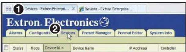
First Tab, Devices Selected Second Tab, Format Editor Selected

Figure 119. Devices and Format Editor
The Devices page opens (see figure 120).
- Choose the encoder connected to the VN-Matrix network in step 3 (see figure 120, ①).

Figure 120. Devices Page
- From the Actions bar located at the bottom of the Devices page, click Format (2). The Source Format dialog box opens.
- Select auto from the Mode drop-down list (see figure 121, ①).

Figure 121. Source Format Menu
- Select from the Phase drop-down list (2).
-
Use the Color Space drop-down list to select the option that matches the connected source (③).
-
Select manual from the Blanking drop-down list (see figure 121, 4 on the previous page).
- Enter 0 in the Pixels field (5).
- Enter in the Lines field (6).
Leave the Source Format window open.
- Using the right tab (see figure 122, ①), select the Format Editor page (②).
- Select an input mode from the list of source formats (3).
NOTE: If the frame rate or the resolution of the source is already known, select a similar source format. Otherwise, select any source format from the list.

Figure 122. Source Format Editor Page (VN-Matrix 2xx Only)
- Click SaveAs (4), to save the resolution.
- In the Save Source Format As dialog box, enter a name for the new source format and click OK (see figure 123).

Figure 123. Saving a Source Format
NOTES:
- Resolutions must be saved using the following format at the beginning of the filename:
x - The end of the filename may contain identifying characters.
Examples:
640 x 400 85p
640 x 400 85p TEST
720 x 480 59.94p HDFrEND
- The name of the new source is listed above the source format properties (see figure 124, 1).

Figure 124. New Source Format Saved
- Return to the left tab (see figure 125, ①) where the Source Format dialog box is open. Note the values in the Line Count and Line Period (ms) fields (②).
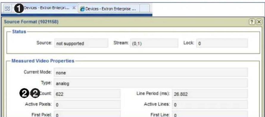
Figure 125. Source Format Line Count and Line Period (ms)
- Using the format editor located on the right tab, make sure the new source is selected from the Source Formats list (see figure 126, ①) panel and enter the values from step 20 into the Line Count and Line Period (ms) fields on the right panel (Source Format - 1280 x 600 60p Test) (②).

Figure 126. Enter Values Into the Source Format Editor Page
- Click Save (3), to save the resolution.
- Click the left tab (see figure 127, ①).

Figure 127. First Tab, Devices Selected
-
Click Devices (②).
-
Force a resync of the source by selecting auto from the Mode drop-down list (see figure 128, ①).

Figure 128. Force a Resync of the Source
-
The name of the new source created in step 16 is now visible in the Current Mode field (②). If the new source name is not visible, check these items.
-
Refresh the Source Format dialog box. Close, then open the dialog box by clicking Format from the Actions menu bar.
- Is the source still connected or if the source is a PC, is the PC still active or has it entered hibernate mode?
- Is the new source name in the Mode drop-down list? If not, use the right tab (Source Format Editor) and make sure the new source is saved.
-
Check that values entered into the Source Format Editor dialog box (step 21) were input correctly.
-
The Measured Video Properties panel now displays information about the new source.
NOTE: The loop-through display can now show an image. The edges of the image can be missing since the image is not properly adjusted yet.
- Note the values in the First Pixel (see figure 129, ①) and First Line fields (②).

Figure 129. Source Format Menu First Pixel and First Line Values
- Using the right tab (see figure 130, ①), on the Format Editor page (②), enter the values that were noted in step 28 into the First Pixel (③) and First Line (④) fields.
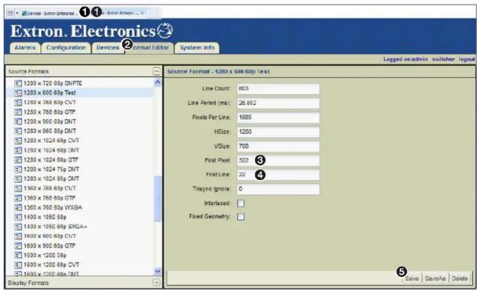
Figure 130. Enter Values Into the Source Format Editor Page
-
Click Save (5), located at the lower right corner of the page, to save the resolution.
-
Return to the left tab (Source Format menu) (see figure 131, ①) and select auto from the Mode drop-down list (②) to force a resync of the source.
NOTE: Although the overall image can still look incorrect, the loop-through display now has its top left corner correctly positioned and there should be no cropping on this edge of the image. If the top left corner is still not correctly positioned, fine tune the image position. Alter the value of the First Pixel field on the Source Format Editor (right tab) dialog box, force a resync of the source (using the left tab, Source Format menu), and check the image on the loop-through display again.

Figure 131. Force a Resync of the Source
-
Click the right device tab (see figure 132, ①).
-
Select the Format Editor (2).
-
In the Source Format panel, adjust the Pixels Per Line field (③) to size the image correctly.
Be sure to click the Save button each time the line is adjusted (4).
NOTE: The pixels per line may or may not be close to the required value depending on the mode chosen as the starting point in step 16. A suitable starting value can be estimated by adding together the values of the Active Pixels and First Pixel fields shown in the Source Format dialog box (left tab in this procedure).

Figure 132. Enter Values Into the Source Format Editor Page
- Use the fine line moiré test pattern on the display to adjust this field.
NOTE: If a fine line moiré test pattern is not available, then this field can be adjusted by monitoring the right side of the image and setting the value so that adding or subtracting 1 pixel either shows all of the image or crops the last pixel.
- With the fine line moiré test pattern displayed, there should be no aliasing (banding) visible in the image.
- If banding is visible and the right side of the image is missing, reduce the Pixels Per Line value by 20 or 30 pixels.
- If banding is visible and all of the image is shown, increase the Pixels Per Line value by 20 or 30 pixels.
- Return to the left tab (Source Format menu) (see figure 133, ①) and select auto from the Mode drop-down list (②) to force a resync of the source. Check the display for banding.

Figure 133. Force a Resync of the Source
-
Repeat steps 34 and 35, adjusting the number of pixels added or subtracted until there is no banding in the image.
-
Using the left tab (Source Format menu), note the value of the First Pixel field (see figure 134, ①).
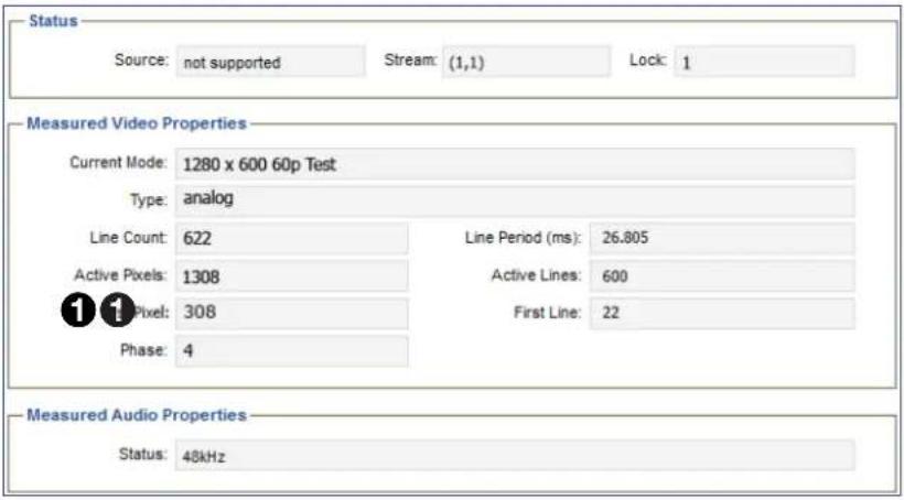
Figure 134. Note Source Format Menu Value
- Click the right tab (Source Format Editor page), (see figure 135, ①) and enter the value from step 37 into the First Pixel field (②).

Figure 135. Enter Values Into the Source Format Editor Page
-
Click Save (③), located at the lower right corner of the page, to save the resolution.
-
Click the left tab (Source Format menu), (see figure 136, ①) and select auto from the Mode drop-down list to force a resync of the source (②).
NOTE: The loop-through display now displays the left side of the image correctly.
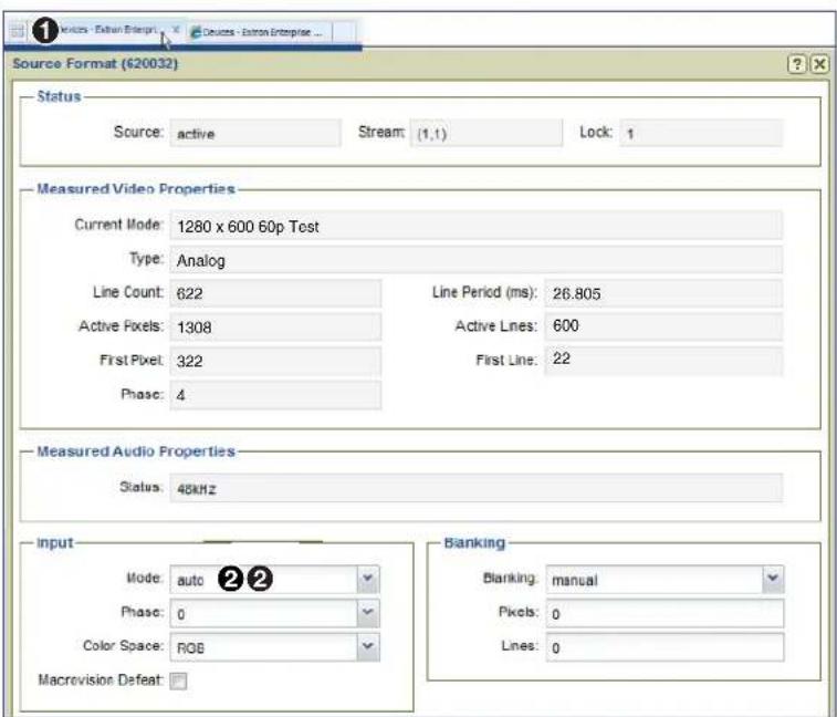
Figure 136. Force a Resync of the Source
- Click the right tab (Source Format Editor), (see figure 137, ①) and adjust the Pixels Per Line value (②) by plus or minus one pixel to see if this improves image sharpness. Click the Save button (③) each time the source is adjusted.
When you are satisfied with the image, proceed to step 42.
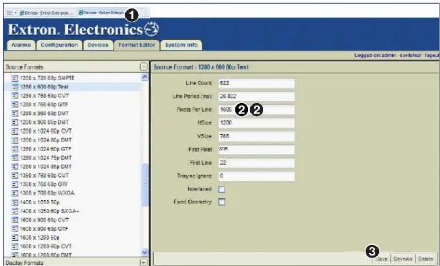
Figure 137. Enter Values Into the Source Format Editor Page
- Click the left tab (Source Format menu), (see figure 138, ①) and force a resync of the source by reselecting auto from the Mode drop-down list (②).

Figure 138. Force a Resync of the Source
NOTES:
- Check the positioning of the image and adjust if necessary (First Pixel and First Line fields on the Source Format Editor page).
- Check for aliasing in the moiré pattern and fine tune the Pixels Per Line field on the Source Format Editor page if required.
- Check that the right edge of the image is properly displayed.
- Adjustments made to the Pixels Per Line field will affect the aliasing in the moiré and the right edge of the image.
- Resync the source each time an adjustment is made.
-
Repeat this process to fine tune the displayed image.
-
Select auto from the Phase drop-down list (see figure 138, ③).
- Select auto from the Blanking drop-down list (4).
- The new source format is now correctly configured. If necessary, see Creating a New Display Format (Output Mode) on page 146 for information on how to create a corresponding display format.
Creating a New Display Format (Output Mode)
One of the issues encountered using various graphic sources with VN-Matrix encoders and decoders is that the encoder often produces a loop-through image stating it has detected a valid input mode, but the decoder displays a splash screen stating "No Matching Output Mode."
Use the following procedure to create a custom display format (output mode) that is automatically selected by the decoder when it sees the corresponding input mode from the encoder.
NOTE: Before starting this procedure, there must be an active input source connected to a VN-Matrix 2xx encoder (output modes of the VN-Matrix 3xx are fixed) and the source format must be correctly configured (displayed properly).
- Open a web browser on the control PC and log into the VNM Enterprise Controller. See Accessing the Web-based User Interface on page 11 for information on how to login.
- Duplicate the web-based user interface of the VNM Enterprise Controller using a second browser tab. Leave both browser tabs open as they are required to complete this procedure.
- Click the left tab (see figure 139, ①). Select the Devices page (②) and choose a VN-Matrix 2xx series decoder from the device list (③). A checkmark appears in the checkbox to the left of the decoder row.

Figure 139. Devices Page
- From the Actions menu bar located at the bottom of the Devices page, click Configure (4).
The Configure Device Settings dialog box opens (see figure 140).
- Select enable from the Mode drop-down list (see figure 140, ①). Click the X in the upper right corner of the dialog box (②) to close the Configure Device Settings dialog box.

Figure 140. Configure Device Settings Dialog Box
- Use the Switcher page (see About the Switcher Page on page 89) to create a connection between the required source format and a decoder.
NOTE: The decoder must have a display connected to the DVI-I Out/Loop connector.
-
Click the right tab, (see figure 141, ①) and select the Format Editor page (②).
-
Select an output mode from the display formats panel (③).
NOTE: Select a display format from the list that closely matches the properties of the new custom display format that is being created.

Figure 141. Display Format Editor Page
-
Make sure that the Manual button, located at the bottom of the page, is selected (4).
-
Enter the required values into the Active Pixels (5), Active Lines (6), and Frame Rate fields (7).
-
Click CVT (8) located at the bottom of the page.
Notice that most of the remaining fields are now grayed out (see figure 142).

Figure 142. Display Format Editor Page
- Click Save As, located at the lower right corner of the page, to save the display format (see figure 142, ①).
- In the Save Display Format As dialog box, enter a name for the new display format and click OK (see figure 143).
NOTES:
- Resolutions must be saved using the following format at the beginning of the filename:
x . - The end of the filename can contain any identifying characters.
Examples:
$$ 6 4 0 \times 4 0 0 8 5 p $$
$$ 6 4 \emptyset \times 4 0 \emptyset 8 5 p T E S T $$
$$ 7 2 0 \times 4 8 0 5 9. 9 4 p H D F r E N D $$
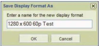
Figure 143. Save a Display Format
- After saving the new display format, note the grayed out fields are updated revealing the timing details of the required display format.
- Using the left browser tab, select the Devices page (see Creating a New Display Format (Output Mode) on page 146) and choose a VN-Matrix decoder from the device list.
- From the Actions menu bar at the bottom of the Devices page, click Format. The Display Format dialog box opens (see figure 144).
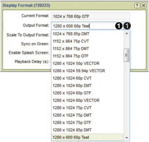
Figure 144. Display Format Menu
- Select the new display format created in step 13 from the Output Format drop-down list (see figure 144, ①). The new display format is applied and the image is displayed.
Deleting Formats
NOTES:
- The default resolutions provided with the VNM Enterprise Controller cannot be deleted.
- Custom resolutions that are being used by any active VN-Matrix device cannot be deleted.
To delete a custom resolution format, select a resolution and click Delete located at the lower right corner of the Format Editor page (see figure 145 on page 150).
About the Source Format Editor
To view or change the properties of a source format:
- Click the right tab, (see figure 145, ①).
- Click the Format Editor tab (②).
The Format Editor page opens.
- Click the Source Formats bar to open a list of source formats (③).
- Select the desired source format (④). The properties of the selected resolution are listed in the Source Format panel on the right (⑤).
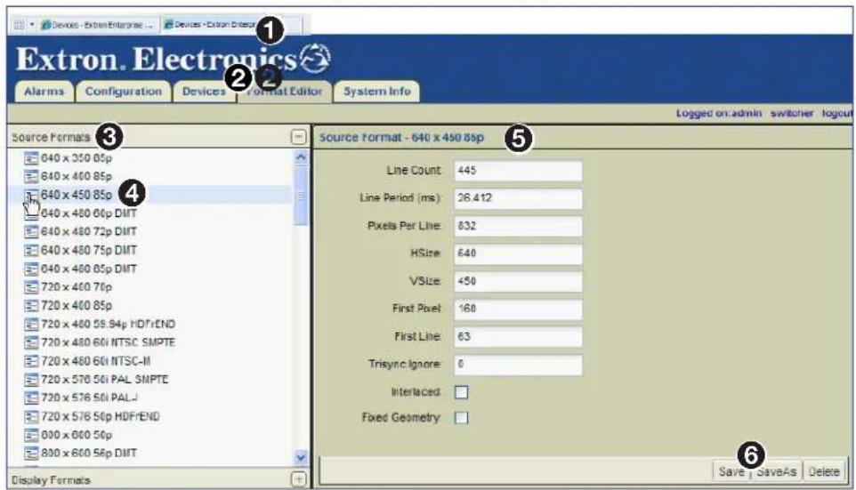
Figure 145. Source Resolution Properties
To create a new source format, modify the desired fields in the Source Format panel and click SaveAs in the lower right corner (6), to save the resolution to the Source Formats list with a new name. For additional information on creating source formats, see Creating a New Source Format (Input Mode) on page 132.
NOTES:
- Resolutions must be saved using the following format at the beginning of the filename:
x . - The end of the filename can contain any identifying characters.
Examples:
640 x 400 85p
640 x 400 85p TEST
720 x 480 59.94p HDFrEND
• Line Count — Specify the number of horizontal lines of information.
• Line Period (ms) — Specify how often the horizontal lines of information are updated.
- Pixels Per Line — Specify how many pixels are used to create each line of information.
- HSize — Specify the horizontal resolution (number of pixels wide) from the source.
- VSize — Specify the vertical resolution (number of pixels high) from the source.
- First Pixel — Specify the position of the first active pixel in the line.
- First Line — Specify the position of the first active line in the frame.
- Trisync Ignore — Zero for all source types. 100 for source types using tri-level sync.
• Interlaced — Check this box to use interlaced video. - Fixed Geometry — This function is currently not implemented.
About the Display Format Editor
- Select the Format Editor tab (see figure 146, ①).
- Click the Display Formats bar (②) to open a list of display resolutions.
- Select the desired source format resolution (③). The properties populate the Display Format panel on the right (④).

Figure 146. Display Resolution Properties
To create a new display format, modify the Display Format panel fields on the right as needed, then click SaveAs (5) to save the resolution to the Display Formats list. For additional information on creating display formats, see Creating a New Display Format (Output Mode) on page 146.
NOTES:
- Resolutions must be saved using the following format at the beginning of the filename: width x height rate(p).
- The end of the filename can contain any identifying characters.
Examples:
$$ 6 4 0 \times 4 0 0 8 5 p $$
$$ 6 4 \emptyset \times 4 0 \emptyset 8 5 p T E S T $$
$$ 7 2 \emptyset \times 4 8 \emptyset 5 9. 9 4 p H D F r E N D $$
• Active Pixels — Specify the horizontal resolution (number of pixels wide).
• Active Lines — Specify the vertical resolution (number of pixels high).
• Total Pixels — Specify the total number of pixels (including syncs and blanking).
• Total Lines — Specify the total number of lines (including syncs and blanking).
- Horizontal Left Border — Specify the horizontal size of the left outer border on the display.
• Vertical Top Border — Specify the vertical size of the top outer border on the display.
- Horizontal Right Border — Specify the horizontal size of the right outer border on the display.
- Vertical Bottom Border — Specify the vertical size of the bottom outer border on the display.
- Horizontal Front Porch — Use this field to properly fit the image on the display. This field shifts the image to the left or right and is directly related to the Horizontal Back Porch field. If an adjustment is made to this field, it is recommended to adjust the Horizontal Back Porch to compensate for the shifted image.
- Vertical Front Porch — Use this field to properly fit the image on the display. This field shifts the image up or down and is directly related to the Vertical Back Porch field. If an adjustment is made to this field, it is recommended to adjust the Vertical Back Porch to compensate for the shifted image.
• Horizontal Sync Width — Specify the width (in pixels) of the horizontal sync pulse.
• Vertical Sync Width — Specify the width (in lines) of the vertical sync pulse.
- Horizontal Back Porch — Use this field to properly fit the image on the display. This field shifts the image left or right and is directly related to the Horizontal Front Porch field. If an adjustment is made to this field, it is recommended to adjust the Horizontal Front Porch to compensate for the shifted image.
- Vertical Back Porch — Use this field to properly fit the image on the display. This field shifts the image to the up or down and is directly related to the Vertical Front Porch field. If an adjustment is made to this field, it is recommended to adjust the Vertical Front Porch to compensate for the shifted image.
• Horizontal Sync Polarity — Select a positive (pos) or negative (neg) horizontal sync.
• Vertical Sync Polarity — Select a positive (pos) or negative (neg) vertical sync.
• Frame Rate — Specify the refresh rate of the video in Hz (frames per second).
- Pixel Clock Frequency — Specify the pixel clock frequency. The higher the frequency of the pixel clock, the more pixels that will appear across the screen.
- Margins — This is a legacy control that is used with input sources that contain a colored border used to accommodate displays that have wide bezels.
- Reduced Blanking — This is a control that is usually required for wide-screen modes. This control accommodates input sources containing active pixels that extend past the normal (blanking) region.
- Manual — By default, this button is selected. This button enables modification of all the display resolution properties.
- CVT — Check to select the coordinated video timing (CVT) standard. This is a VESA standard.
- GTF — Check to select the generalized timing formula (GTF) standard. This is a VESA standard.
About Alarms
This section provides information on:
- Overview
- Alarms Page
• Alarm Type Reference Tables
Overview
The VN-Matrix system is configured to generate alarms for error conditions. A list of these error conditions and their meanings are presented on the following pages.
Alarms can be monitored using the Alarms page. Alarm conditions, when triggered, remain active for the duration of the error condition and for an additional five seconds after the error is cleared.
Alarms Page
This page is accessed by selecting the Alarms tab (see figure 147).

Figure 147. Alarms Page
The Alarms page enables a user to sort and monitor system alarms. For information on alarm types, see Alarm Type Reference Tables on page 155.
A ID Number — The ID number of the alarm.
B Severity Icons — The alarm severity is indicated by a colored icon.

A device under active control showing warning alarms.

A device under active control showing critical alarms.
C Alarm Description — The type of alarm. The information listed here is directly related to the Alarm Type column in the Alarm Type Reference Tables on page 155.
D Device — The device ID of the VNM device is shown in this column.
E Name — The name assigned to the device by the user.
F Device Type — The type or model number of the connected device.
G Raised Time — The date and time the alarm first occurred.
H Controller — The IP address of the device acting as the system controller.
Sorting Alarms by Column
Columns can be sorted by clicking directly on any of the column names. Clicking on a column name sorts the list in ascending or descending order. Figure 148 shows the alarms sorted by raised time (②). The Raised Time column is darkened and contains a ▼ icon to show that the devices are sorted by the raised alarm time in ascending order.
Hovering over the right side of a column name reveals a pull-down arrow that, when clicked, accesses the advanced column sorting menu. Use this menu to sort columns in ascending or descending order.
Sorting Alarms by Group
Alarms can be sorted in groups using the Group By menu (see figure 148, ①).

Figure 148. Grouping Alarms
The following grouping options are available.
NOTES:
- After selecting a grouping option, groups can be further sorted using column sorting (see Sorting Devices by Column on page 38). Figure 148 shows the alarms sorted by raised time in ascending order (②).
-
Grouped alarms are expanded and collapsed by clicking on the square icon located next to the group name (③).
-
None — Removes group sorting.
• Severity — Groups the alarms by critical severity and warning severity.
• Type — Groups the alarms by their description (type). - Device — Groups the alarms by device ID. In other words, this option links each alarm to the device it originates from.
- Controller — Groups the alarms by system controller. When a VN-Matrix system contains more than one system controller, this option links alarms to each system controller.
- Expand All — Reveals all alarms. The alarms display under the appropriate group name.
- Collapse All — Hides all alarms. Only the group names are displayed on the page.
Alarm Type Reference Tables
Encoders
| CLI Alarm Alarm Description Fault Description | Alarm Type | ||
| NOSRC No Source No input source is connected. | Critical, Reporting | ||
| BADSRCSYN Bad Source Syncs An input source is connected but the sync timing is not recognized.(Unable to input source due to bad sync measurements) | Critical, Reporting | ||
| NOSDILOCK | No SDI Source Lock An | SDI source is connected but the signal timing is not recognized.(An SDI source is present but the PLL lock failed). | Critical, Reporting |
| NOSDIMODE | Unsupported SDI Mode | The connected SDI source mode not supported. | Critical, Reporting |
| NOMODE Unsupported Mode The connected source is not supported; a user-mode must be created. | Critical, Reporting | ||
| BADSRC | Bad Source A source is connected and syncs have been detected, but it is not possible to make active pixel measurements. | Critical, Reporting | |
| PHASING Analog Phasing Failure The analog pixel clock auto-phasing process failed. | Warning, Reporting | ||
| HWNOVIDEO | Hardware Encoding Error | The hardware is unable to encode the input video. | Critical, Reporting |
| UNSUPAUDIOSRC | Unsupported Audio Source | The digital audio source has a bad or unsupported clock rate. | Critical, Reporting |
| BADAUDIOSRC | Bad Audio Source | The audio source is not valid for the current video source. | Warning, Reporting |
| VIDEOOVERLOAD | Data Rate Overload | The system is not able to process the source at the current settings; increase the compression.(The compressed data rate is too high, increase the compression). | Critical, Reporting |
| NWOVERLOAD | Network Overload | The network is dropping too many packets. | Warning, Reporting |
| BADREVAUDIO | Bad Reverse Audio | The reverse audio channel contains no data or has a large number of dropouts. | Warning, Reporting |
Decoders
| CLI Alarm Alarm Description Fault description | Alarm type | ||
| NOVIDEO | No Decoder Video Data | A stream is assigned but the decoder is not receiving video data. | Warning, Reporting |
| NOMATCH | No Decoder Mode A video | deo stream is assigned but the decoder does not recognize the format.(The decoder cannot output the current input stream). | Warning, Reporting |
| NOSRCREPORT | No Source Report A video | deo stream is assigned but there is no source present at the encoder.(The encoder is reporting "No Source" to the Decoder). | Warning, Reporting |
| RECAUDIO Recovered Audio The decoder has recovered missing audio packets. | Warning, Reporting | ||
| NOAUDIO | No Decoder Audio Data | An audio stream is assigned, but the decoder is not receiving audio data. | Warning, Reporting |
| BADAUDIO | Bad Audio At Decoder The decoder is receiving poor quality audio data. | Warning, Reporting | |
| BADAPLL | Bad Audio PLL The decoder is having problems synchronizing to the audio data. | Warning, Reporting | |
| VIDEODROP | Video Network Packets Dropped | Excess video data has been dropped in the network. | Warning, Reporting |
| BUFFEROVERFLOW | Decoder Buffer Overflow | Too many data frames at the decoder; reduce the pipeline delay. | Warning, Reporting |
| BUFFERUNDERFLOW | Decoder Buffer Underflow | Too few data frames at the decoder; increase the pipeline delay. | Warning, Reporting |
| BADVPLL | Bad Video PLL The decoder is having problems synchronizing to the video data. | Warning, Reporting | |
| NOANC No Decoder ANC Data An ANC stream is assigned, but the decoder is not receiving the ANC data. | Warning, Reporting | ||
| BADANC | Missing ANC at Decoder | The decoder is receiving poor quality ANC data. | Warning, Reporting |
| RECANC Recovered ANC The decoder has recovered from missing ANC packets. | Warning, Reporting | ||
| GENLOCKNOSOURCE | No Genlock Source Present | There is no reference genlock source present. | Critical, Reporting |
| GENLOCKNOLOCK | No Genlock Source Lock | The reference genlock signal is invalid. | Critical, Reporting |
| GENLOCKMISMATCH | Genlock Source Mismatch | The genlock reference signal mismatches the required output mode. | Critical, Reporting |
| UNSUPAUDIOTYPE | Unsupported Audio Type | Audio data type not supported by current hardware. | Critical, Reporting |
Encoder/Decoder
| Alarm Description Fault Description Alarm Type | |||
| AUDIOVERRANGE | Audio Input Overrange | The analog input level is too high for the current range setting. | Warning, Reporting |
| BADAUDIOHW | Bad Audio Hardware Reporting | The audio hardware has failed or is not present. | Critical, reporting |
System Controller
| Alarm Description Fault Description Alarm Type | |||
| OVERTEMP | Over Temperature The h | hardware is too hot and operation will likely be erratic. | Warning, Reporting |
| BADDEVICE | Bad Device The device is not properly communicating with the controller. | Critical, Reporting | |
| RTPHOLDOFF RTP Stream Holdoff The RTP data stream has been temporarily disabled due to excess packet drops. | stream has been temporary disabled due to excess packet drops. | Critical, Reporting | |
Dual (Redundant) Controller Configuration
This section details the basic information needed to configure the settings of dual VNM Enterprise Controllers. For information on how to set up a single controller, see Single VNM Enterprise Controller Configuration on page 14.
This section provides information on:
- Setup Overview
- Configuring Dual VNM Enterprise Controllers
- Configuring Dual Enterprise Controllers as the System Controller
- Configuring VN-Matrix Devices for Dual VNM Enterprise Controllers
- About the Cluster Properties Pages
NOTE: For additional configuration information, see Advanced Controller Configuration on page 19. Configure each VNM Enterprise Controller identically.
Setup Overview
- Use a network switch to connect the primary VN-Matrix network to the rear panel Ethernet connector (eth0) of each VNM Enterprise Controller (see Rear Panel Features on page 9).
- Use an RJ-45 crossover cable to connect the VNM Enterprise Controller Ethernet connectors (eth1) together (see figure 2 on page 3 and Rear Panel Features on page 9).
- Power on each VNM Enterprise Controller, all VN-Matrix devices present in the system, and all necessary devices (see Power Down Procedure on page 12).
- Connect a control PC to the VN-Matrix network and navigate to the web-based user interface of each VNM Enterprise Controller (see Accessing the Web-based User Interface on page 11).
- Configure the settings of each VNM Enterprise Controller (see Configuring Dual VNM Enterprise Controllers on page 159).
- Configure the VNM Enterprise Controller pair to act as the controller for the VN-Matrix system (see Configuring Dual Enterprise Controllers as the System Controller on page 165).
- Configure the devices within the VN-Matrix system (see Configuring VN-Matrix Devices for Dual VNM Enterprise Controllers on page 171).
- If necessary, update the license of each VNM Enterprise Controller (see Controller Firmware and License Updates on page 179).
- Power down each VNM Enterprise Controller and all configured devices (see Power Down Procedure on page 12). After a few seconds, power on each VNM Enterprise Controller and all necessary devices.
Configuring Dual VNM Enterprise Controllers
This section details how to set up and configure dual (redundant) VNM Enterprise Controllers.
Configuring the Network Settings (Eth0)
NOTES:
- The VNM Enterprise Controllers should not be paired when configuring the network settings. For information on how to unpair VNM Enterprise Controllers, see Unpairing controllers on page 174.
- Be aware that unpairing and then pairing a VNM Enterprise Controller deletes device configuration files, presets, and custom input or output modes.
- Each VNM Enterprise Controller must use an IP address that contains the same network prefix and subnet.
• Each VNM Enterprise Controller must use the same subnet mask address.
Each VNM Enterprise Controller is pre-configured with the following network settings.
IP address: 192.168.254.254
Subnet mask: 255.255.255.0
Gateway: 192.168.254.1
MTU: 1500
NOTE: With these default settings, devices connected to the VN-Matrix network must use IP addresses within the range of 192.168.254.2 through 192.168.254.253 and use the same subnet mask.
Use the following procedure to change the network settings of each VNM Enterprise Controller.
-
Log into the VNM Enterprise Controller (see Accessing the Web-based User Interface on page 11).
-
Click the Configuration tab (see figure 149, ①).
The Configuration page opens.

Figure 149. Configuration Page — Configuring the Network Setting
-
Click the Network link under Device Properties (②).
-
In the Internet Protocol panel, change the IP Address, Netmask, Gateway, and MTU fields as necessary (③).
NOTE: The default value of 1500 in the MTU field is the correct setting in most instances.
-
Click Apply Changes to save the configuration (4). The controller network settings are now applied.
-
Repeat steps 1 through 5 to configure the other VNM Enterprise Controller.
-
Configure the IP address of the control PC so that it is within the address range of the VNM Enterprise Controller.
NOTE: Complete this step only if the IP address of each VNM Enterprise Controller is using a network prefix or subnet other than 192.168.254.xxx.
- If necessary, restart the control PC to save the new network configuration.
Setting the Role of the Primary Enterprise Controller
Use the following procedure to set the role of the redundant primary VNM Enterprise Controller (see Accessing the Web-based User Interface on page 11).
- Log into the redundant primary VNM Enterprise Controller and click the Configuration tab.
The Configuration page opens (see figure 150, ①).

Figure 150. Configuration Page — Redundant Primary Role Setup
- Under Device Properties, click the Role link (②).
- From the Device Mode drop-down list, select redundant_primary (③).
NOTE: For information on the other device modes, see Role Page on page 22.
- Click Apply Changes to save the configuration (4).
NOTES:
- The web-based user interface returns to the Login page after saving the configuration. This may take a few seconds.
- After completing this procedure, the Cluster Page (see page 172) and Node Test Page (see page 169) are available on the Configuration page.
Setting the Role of the Secondary Enterprise Controller
Use the following procedure to set the role of the redundant secondary
VNM Enterprise Controller (see Accessing the Web-based User Interface on page 11 for information on how to login).
- Log into the redundant secondary VNM Enterprise Controller and click the Configuration tab.
The Configuration page opens (see figure 151, ①).

Figure 151. Configuration Page — Redundant Secondary Role Setup
- Click the Role link (②).
- From the Device Mode drop-down list in the Device Mode panel, select redundant_secondary (③).
NOTE: For information on the other device modes, see Role Page on page 22.
- Click Apply Changes (④) to save the configuration.
NOTE: The web-based user interface returns to the login page after saving the configuration. This may take a few seconds.
Configuring the Primary Enterprise Controller Time Settings
Use the following procedure to configure the time settings of the redundant primary VNM Enterprise Controller (see Accessing the Web-based User Interface on page 11 for information on how to login).
- Log in to the redundant primary VNM Enterprise Controller and click the Configuration tab.
The Configuration page opens (see figure 152, ①).
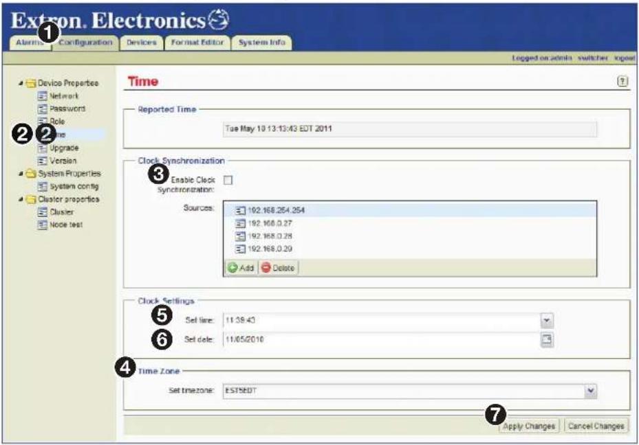
Figure 152. Configuration Page — Primary Controller Time Setup
- Under Device Properties, click the Time link (②).
- Make sure Enable Clock Synchronization is not checked (③).
NOTE: If Enable Clock Synchronization is checked, the Set time (5) and Set date (6) fields are dimmed.
- Select the desired time zone from the Set timezone drop-down list (4) and click Apply Changes (7).
- Enter the time in the Set time field (⑤).
- Use the HH:MM:SS (hours:minutes:seconds) format based on the 24-hour clock. For example, 08:25:00 or 20:35:10.
- Enter or select the date in the Set date field (6).
• Use the MM/DD/YYYY (month/day/year) format. For example, 05/14/2012.
- Click Apply Changes (⑦) to save the configuration.
Configuring the Secondary Enterprise Controller Time Settings
Use the following procedure to configure the time settings of the redundant secondary VNM Enterprise Controller.
- Log in to the redundant secondary VNM Enterprise Controller (see Accessing the Web-based User Interface on page 11) and click the Configuration tab.
The Configuration page opens (see figure 153, ①).

Figure 153. Configuration Page — Secondary Controller Time Setup
- Under Device Properties, click the Time link (②).
- Select the desired time zone from the Set timezone drop-down list (③). Choose the same time zone selected for the redundant primary VNM Enterprise Controller.
- In the Clock Syncronization panel, check Enable Clock Synchronization (4). This syncs the time settings of this VNM Enterprise Controller to the devices listed in the Sources field.
- Click Add (⑤) to open the IP address dialog box. Enter the IP address of the redundant primary VNM Enterprise Controller and click OK to close the dialog.
- Click Apply Changes to save the configuration (6).
Configuring Dual Enterprise Controllers as the System Controller
This section details how to assign the dual VNM Enterprise Controllers as the system controller. Before proceeding, make sure the procedures detailed in Configuring Dual VNM Enterprise Controllers on page 159 are completed.
NOTE: For information on how to configure a single VNM Enterprise Controller as the system controller, see Single VNM Enterprise Controller Configuration on page 14.
Adding the VNM Enterprise Controllers to the Controller List
Use the following procedure to add the VNM Enterprise Controllers to the controller list (see Accessing the Web-based User Interface on page 11).
- Log in to the redundant primary VNM Enterprise Controller and click the Configuration tab.
The Configuration page opens (see figure 154, ①).

Figure 154. Configuration Page — Adding Controllers to the Controller List
- Click the System config link (②).
- In the Controllers field, click Add (③).
- Enter the cluster IP address of the VNM Enterprise Controller pair into the dialog box (not shown) and click OK.
NOTE: If necessary, clear the Controllers field. Highlight the IP addresses and click Delete.
- Click Apply Changes to save the configuration (4).
The VNM Enterprise Controller restarts the user interface and is assigned as the system controller.
- Log in to the redundant secondary VNM Enterprise Controller and repeat this procedure.
Configuring the Transport Protocol
Use the following procedure to configure the transport protocol that will be used throughout the VN-Matrix system (see Accessing the Web-based User Interface on page 11 for information on how to login).
- Log into the redundant primary VNM Enterprise Controller and click the Configuration tab.
The Configuration page opens (see figure 155, ①).

Figure 155. Configuration Page — Configuring the Transport Protocol
- Click the System config link (②).
- From the Protocol drop-down list (③), select the preferred transport protocol.
NOTE: The default transport protocol is Unicast. For more information on transport protocols, see Transport Protocols Used for Streaming on page 4.
- Click Apply Changes to save the configuration (4).
- Log into the redundant secondary VNM Enterprise Controller and repeat this procedure.
Setting the Cluster IP Address
Use the following procedure to set the cluster IP address (see Accessing the Web-based User Interface on page 11 for information on how to login).
NOTE: When the VN-Matrix system is first set up, this procedure should be performed on both the primary and secondary controllers before pairing.
- Log into the redundant primary VNM Enterprise Controller and click the Configuration tab.
The Configuration page opens (see figure 156, ①).

Figure 156. Configuration Page — Setting the Cluster IP Address
- Click the Cluster link (②).
- Enter the desired IP address into the Cluster IP Address field (③).
NOTE: The cluster IP address must have the same network prefix and subnet as the IP address entered in step 4 of Configuring the Network Settings (Eth0) on page 159.
- Click Apply Changes (④) to save the setting.
- Log into the redundant secondary VNM Enterprise Controller and repeat this procedure.
Setting the Crossover Subnet IP Address (Eth1)
A crossover cable is connected between the eth1 ports of a VNM Enterprise Controller pair. By default, the crossover subnet IP address for this port is 192.168.253.0. In most cases, this is acceptable and does not need altered.
NOTES:
- If a network prefix or subnet of 192.168.253.xxx is used for the main eth0 ports, a crossover subnet IP address must be created that uses a different network prefix or subnet.
- The Crossover Subnet field can only be changed when the VNM Enterprise Controllers are unpaired (see Unpairing controllers on page 174).
- The Crossover Subnet field must be individually set on each VNM Enterprise Controller within the cluster. The entered values must also be identical.
- A crossover cable must be directly connected between the eth1 ports of a VNM Enterprise Controller pair without using extra network equipment (such as a switch or router).
If necessary, use the following procedure to change the crossover subnet IP address (see Accessing the Web-based User Interface on page 11 for information on how to login).
- Log into the redundant primary VNM Enterprise Controller and click the Configuration tab.
The Configuration page opens (see figure 157, ①).
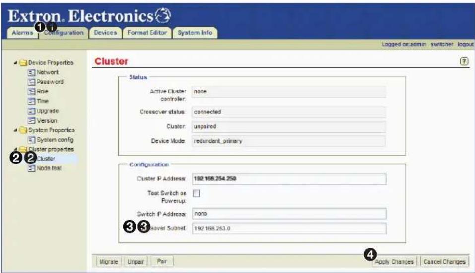
Figure 157. Configuration Page — Changing the Crossover Subnet
- Click the Cluster link (②).
- In the Crossover Subnet field (③), enter the desired crossover subnet IP address.
- Click Apply Changes to save the configuration (4).
- Log into the redundant secondary VNM Enterprise Controller and repeat this procedure.
NOTE: When a crossover cable connects the primary and secondary VNM Enterprise Controllers and the crossover subnet address on both (3) are set identically, the Crossover status field displays connected.
Node Test Page
This page is used to test the VNM Enterprise Controller pair by determining which controller, primary or secondary, has the best communication with the devices in the VN-Matrix system at power up (see figure 158). The VNM Enterprise Controller that communicates best with these devices becomes the Primary and the other unit becomes the Secondary.
The tested devices are called nodes. This list is created by entering IP address values of VN-Matrix devices into the Sources list.

Figure 158. Node Test Page
Adding nodes
NOTE: Nodes can only be added on a VNM Enterprise Controller that is unpaired.
- Using a web browser, navigate to the web-based user interface by entering the physical IP address (eth0) of the redundant primary VNM Enterprise Controller.
- Select the Configuration page (see figure 158, ①).
- Click on the Node test link ( ②).
- Click Add at the bottom of the Sources list (3).
The following dialog box opens.
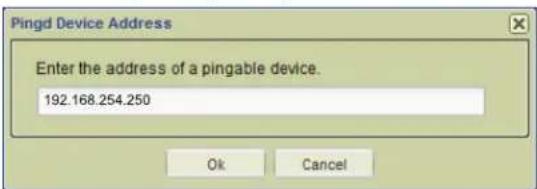
- Enter the desired IP address and click OK.
- Continue to add the IP addresses of from four to six VN-Matrix devices controlled by the VNM Enterprise Controller pair.
- When finished, click Apply Changes ( 5).
NOTE: The redundant secondary VNM Enterprise Controller automatically matches its Sources list to the redundant primary VNM Enterprise Controller.
Deleting nodes
- Using a web browser, navigate to the web-based user interface by entering the physical IP address (eth0) of the redundant primary VNM Enterprise Controller.
- Select the Configuration page (see figure 158, ① on the previous page).
- Click on the Node test link (②).
- In the Sources list, select the node to delete.
- Click Delete (④) located below the Sources list to remove the selected IP address.
NOTE: The redundant secondary VNM Enterprise Controller automatically matches its Sources list to the redundant primary VNM Enterprise Controller.
Pairing the VNM Enterprise Controllers
NOTE: Before pairing the VNM Enterprise Controllers, the cluster IP address must be set (see Setting the Cluster IP Address on page 167).
Use the following procedure to pair the VNM Enterprise Controllers (see Accessing the Web-based User Interface on page 11 for information on how to login).
-
Using a web browser, navigate to the web-based user interface by entering the physical IP address (eth0) of the redundant primary VNM Enterprise Controller.
-
Click the Configuration tab.
The Configuration page opens (see figure 159, ①).

Figure 159. Configuration Page — Pairing the VNM Enterprise Controllers
-
Click the Cluster link (②).
-
Click Pair (③).
NOTES:
- Pairing the VNM Enterprise Controllers can take several minutes.
- After the VNM Enterprise Controllers are paired, it could be necessary to reconfigure the settings (see Advanced Controller Configuration on page 19).
Configuring VN-Matrix Devices for Dual VNM Enterprise Controllers
For the VNM Enterprise Controller to function properly:
- Update each VN-Matrix device so that the controller address of each device points to the cluster IP address of the VNM Enterprise Controllers and configure each device to operate on the same network as the VNM Enterprise Controllers.
- Access the VNM Enterprise Controller web-based user interface by entering the cluster IP address of the VNM Enterprise Controller pair into the address bar of the web browser.
- Use the web-based user interface to select a device from the Devices page and use the Actions menu bar at the bottom of the page to configure the selected device.
For additional information on configuring VN-Matrix devices to operate with the VNM Enterprise Controllers, see the user guide for each device.
About the Cluster Properties Pages
This section details the control options available using the Cluster and Node Test pages. Procedures relevant to these pages are also detailed in this section.
Cluster Page
The Cluster page is used to view and manage the pairing status of the controller (see figure 160).
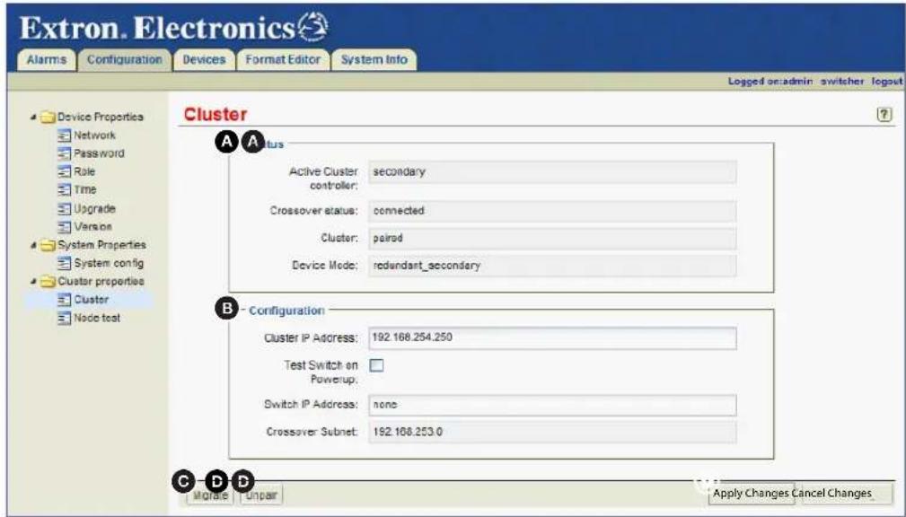
Figure 160. Cluster Page
Status panel (A)
This panel contains four read-only fields that display the following information.
• Active Cluster controller — Displays which VNM Enterprise Controller (primary, secondary, or none) is acting as system primary.
- Crossover status — Displays the status of the crossover link between the primary and secondary VNM Enterprise Controllers.
- Cluster — Displays whether the primary and secondary controllers are paired together or unpaired.
- Device Mode — Displays the role of the controller that is logged into (for example, whether it is the primary or secondary controller).
Configuration panel (B)
Use this panel (see figure 160, Ⓑ on the previous page) to configure the following options.
NOTES:
- The Cluster IP Address, Test Switch on Powerup, and Switch IP Address fields can be configured using any VNM Enterprise Controller within the cluster.
-
The Crossover Subnet field must be individually set on each VNM Enterprise Controller within the cluster. The entered values must be identical.
-
Cluster IP Address — This field is used to set the cluster (shared) IP address for the controller pair. This IP address is used as the controller address by the other devices in the VN-Matrix system. Both the primary and secondary VNM Enterprise Controllers (whichever one is active) use the cluster IP address for all system control communications. For information on setting the cluster IP address, see Setting the Cluster IP Address on page 167.
- Test Switch on Powerup — Selecting this check box causes the primary and secondary VNM Enterprise Controllers, when first powered on, to wait until they are both able to communicate with the network switch before determining which controller (primary or secondary) is the best device to manage the VN-Matrix system.
- Switch IP Address — This field is used to set the IP address of the network switch that is being used in the VN-Matrix system.
NOTE: This field must contain an IP address for the Test Switch on Powerup function to work.
- Crossover Subnet — This field displays the IP address of the crossover subnet Ethernet ports (eth1). The crossover subnet monitors the status of the primary and secondary VNM Enterprise Controllers when the system is configured for redundant operation. For information on setting the crossover subnet, see Setting the Crossover Subnet IP Address (Eth1) on page 168.
NOTE: This field can be edited when the VNM Enterprise Controller cluster is unpaired (see Unpairing controllers on page 174).
Setting the Test Switch on Powerup option
- Select the Test Switch on Powerup check box to activate this option or deselect the check box to deactivate this option (see figure 160, B on the previous page).

- Click Apply Changes (D), to save the setting.
Setting the switch IP address
- In the Switch IP Address field (B), enter the desired IP address.
Switch IP Address: none
- Click Apply Changes (D), to save the setting.
Other cluster control functions
Two buttons are available at the bottom of the Cluster page used to manage the state of the controller pair (see figure 160, Ⓖ on page 172). The functions that are available are Migrate, Pair, and Unpair.
Pair and Unpair share a single button.
- Migrate — Clicking this button causes a controller pair to switch roles. The service provider (primary VNM Enterprise Controller) becomes the backup (secondary VNM Enterprise Controller) and the backup becomes the service provider.
- Pair — Clicking this button causes a set of controllers to pair together which initializes the service (cluster) IP address and sets the units to operate in a shared-role state.
- Unpair — Clicking this button causes a controller pair to unpair which stops the service (cluster) IP address and returns the units to independent states.
NOTE: An unpaired controller is not the same thing as a singleton. After unpairing, the primary and secondary VNM Enterprise Controllers will not perform their role as controllers until they have been paired back up.
Migrating a controller pair
- Using a web browser, navigate to the web-based user interface by entering the physical IP address (eth0) of the primary VNM Enterprise Controller, the physical IP address of the secondary VNM Enterprise Controller, or enter the service (cluster) IP address for the primary and secondary VNM Enterprise Controllers.
- Navigate to the Configuration page.
- Click on the Cluster link (see Cluster Page on page 172).
- Click Migrate at the bottom of the screen.
Migrate
NOTE: The web browser automatically logs out of the web-based user interface and returns to the login page.
Unpairing controllers
- Using a web browser, navigate to the web-based user interface by entering the physical IP address (eth0) of the primary VNM Enterprise Controller, the physical IP address of the secondary VNM Enterprise Controller, or enter the service (cluster) IP address for the primary and secondary VNM Enterprise Controllers.
- Navigate to the Configuration page.
- Click on the Cluster link (see Cluster Page on page 172).
- Click Unpair at the bottom of the screen.
Unpair
NOTE: Unpairing the VNM Enterprise Controllers may take several minutes.
Pairing controllers
See Pairing the VNM Enterprise Controllers on page 171.
System Control
The VNM Enterprise Controller is used to configure and control a VN-Matrix system. When used as part of a larger installation, it is likely that there will be a third party control system that integrates all of the system equipment into a single control interface.
The VMN Enterprise Controller incorporates two methods of control to support this system architecture.
- High Level Interface (HLI) — The HLI is a control protocol that allows users to interface their control system with the devices on a VN-Matrix network. This is the main control protocol used with the VNM Enterprise Controller.
- Command Line Interface (CLI) — The CLI provides low level control of a VN-Matrix device. This is the control protocol that is used by the system controller to communicate with other VN-Matrix devices on the network. The CLI protocol contains a complex instruction set and requires a thorough understanding of VN-Matrix devices and their operation. This complexity makes the CLI unsuitable for most users with limited knowledge of a VN-Matrix system.
NOTE: The Command Line Interface protocol is not thoroughly documented in this user guide.
This section provides information on:
- HLI Overview
- HLI Features
• HLI Connection and Control
• HLI Command Tables
HLI Overview
The HLI is positioned between the CLI and the user control system. The HLI manages the underlying complexity of the CLI and presents a streamlined control method.
The HLI is accessed from the control computer over the VN-Matrix network or by direct connection using the COM1 serial connector (see Rear Panel Features on page 9) on the rear panel of the VNM Enterprise Controller.
HLI commands are sent to the VN-Matrix system using the following programs:
• Telnet (see HLI Connection and Control below).
- VNM Enterprise Controller web-based user interface (see About the Web-based User Interface on page 2).
NOTE: The commands detailed in the HLI command sections are commonly used to communicate with devices on a VN-Matrix network and represent a subset of the HLI command language.
HLI Features
HLI commands:
- Provide a single point of control for all VN-Matrix domains.
- Operate using TCP on port 9996 of the VNM Enterprise Controller.
HLI Connection and Control
HLI commands can be sent from the control computer to the Enterprise Controller using the serial port, the Ethernet port, or using the VNM Enterprise Controller Web-based user interface (see HLI Command Examples on page 212).
Ethernet Connection
The HLI can be accessed using TCP by initiating a Telnet connection to the IP address of the VNM Enterprise Controller on port number 9996.
NOTES:
- If the IP address has not changed, the factory default IP address of a VNM Enterprise Controller is 192.168.254.254.
- Ensure the Telnet service is installed.
Example: Connect to the HLI in Microsoft® Windows® operating systems using the command prompt:
C:> telnet 192.168.254.254 9996
Serial Port (COM) Connection
The VNM Enterprise Controller receives HLI commands from a control computer directly connected to the COM1 serial connector (see Rear Panel Features on page 9).
NOTE: The default configuration settings for the COM1 serial connector are:
- Com port - COM1
- Baud rate - 115200
- Parity bit – None
- Data bit - 8
- Start bit – None
- Stop bit - 1
- Flow control (handshake) – None
Using the VNM Enterprise Controller User Interface
To enter HLI commands into the VNM Enterprise Controller web-based user interface:
- Access the web-based user interface (see Accessing the Web-based User Interface on page 11).
- From the Devices page, select a device. If necessary, multiple devices can be selected by clicking the check boxes located on the left side of the Devices page (see Devices Page Overview on page 36).
- At the bottom of the Devices page, select the Misc menu.
A menu list opens (see figure 161).

Figure 161. Misc Menu — Select "Send HLI Command"
- Select Send HLI command. A HLI command window opens (see figure 162).

Figure 162. HLI Command Window
- To send a command, click in the (enter command line) text box, and enter the desired HLI command. Press
.
The response appears in the lower portion of the window.
Click the X button in the upper right hand corner to close the HLI command window.
HLI Command Tables
HLI commands are listed in the reference section (see HLI Command Overview on page 211).
HLI general commands are used to:
• Control a specific function of a single device
• Build a connection between devices
- Modify the mode of a device
• Retrieve system information and monitor system status
HLI preset commands are used to:
- Launch an action or series of actions
• Control and modify system configurations
HLI Responses
HLI responses are formatted using the Java Script Object Notation (JSON) format. Response strings consist of objects, arrays, and values.

flowchart
graph LR
    A["object"] --> B["["]
    B --> C["string"]
    C --> D[":"]
    D --> E["value"]
    E --> F[]
An object is an unordered set of name or value pairs. An object begins with a left brace ( [ ) and ends with a right brace ( ] ). Each name is followed by a colon ( : ) and the name or value pairs are separated by a comma ( , ).

flowchart
graph LR
    A["array"] --> B["["]]
    B --> C["value"]
    C --> D["["]]
    D --> E[" "]
    E --> F[" "]
    F --> G[" "]
    G --> H[" "]
    H --> I[" "]
    I --> J[" "]
    J --> K[" "]
    K --> L[" "]
    L --> M[" "]
    M --> N[" "]
    N --> O[" "]
    O --> P[" "]
    P --> Q[" "]
    Q --> R[" "]
    R --> S[" "]
    S --> T[" "]
    T --> U[" "]
    U --> V[" "]
    V --> W[" "]
    W --> X[" "]
    X --> Y[" "]
    Y --> Z[" "]
An array is an ordered collection of values. An array begins with a left bracket( [ ) and ends with a right bracket ( ] ). Values are separated by a comma( , ).
value

flowchart
graph TD
    A["string"] --> B["number"]
    B --> C["object"]
    C --> D["array"]
    D --> E["true"]
    E --> F["false"]
    F --> G["null"]
A value can be a string in double quotes, a number, true or false, null, an object, or an array. These structures can be nested.
Controller Firmware and License Updates
This section provides information about:
- Updating the VNM Enterprise Controller License
- Updating the Firmware of a Single Enterprise Controller
- Updating the Firmware of Dual (Redundant) Enterprise Controllers
Updating the VNM Enterprise Controller License
The VNM Enterprise Controller includes a basic license when purchased. Updating the license of the VNM Enterprise Controller enables the VN-Matrix system to operate with the VNM Software Decoder and the VNS 104 Multi-stream Software Decoder.
ATTENTION:
- Click the Configuration tab to open the page (see figure 163, ①).
If login information is required, see Accessing the Web-based User Interface on page 11.

Figure 163. Configuration Page — Updating the Controller License
- Click the System config link (②).
- From the Controllers field in the Configuration panel, select the IP address of the controller that requires a new license (③).
- Click License (④).
The Controller License Management dialog box opens (see figure 164). Keep this window open.
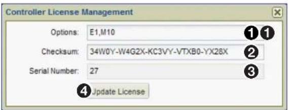
Figure 164. Controller License Management Dialog
-
Contact Extron Sales Support and provide the following information.
-
The serial number of the VNM Enterprise Controller (see figure 164, ③). This can be obtained from the Controller License Management dialog in figure 164, or from the rear panel.
• The order number of the VNM Enterprise Controller.
NOTE: Contact information is available on the last page of this user guide.
- Extron Sales Support provides a structure key and a license key.
• Enter the structure key in the Options field (1).
- Enter the license key in the Checksum field (2).
-
Click Update License (④) to assign the new license settings.
-
Click X in the upper right corner of the dialog box to close dialog box.
Updating the Firmware of a Single Enterprise Controller
Before starting this procedure, go to www.extron.com/download and download the latest version of the VNM Enterprise Controller firmware.
Use the following procedure to update the firmware of a single VNM Enterprise Controller (see Accessing the Web-based User Interface on page 11 for login information).
- Click the Configuration tab (see figure 165, ①).
The Configuration page opens.

Figure 165. Configuration Page — Single Enterprise Controller
- Click the Upgrade link (②).
- Click Browse (③) to open a file browser to navigate to the location of the firmware file. Select the file and click Open.
- Click Upgrade (④) to start the firmware update.
- When the update completes, power down the VNM Enterprise Controller and restart.
Updating the Firmware of Dual (Redundant) Enterprise Controllers
ATTENTION:
The firmware update for dual controllers requires the following steps:
- Download the firmware update from www.extron.com/download.
- Save the device configuration and presets files to a local PC (see Unpair the Controller Cluster on page 186).
-
Unpair the controller cluster (see Unpair the Controller Cluster on page 186).
-
Update the redundant secondary controller (see Update the Redundant Secondary Controller on page 187).
- Update the primary controller (see Update the Primary Controller on page 187).
- Pair the two controllers (see Pair the Controllers on page 188).
- Restore the device configuration and presets files from the local PC (see Restore the Device Configuration and Presets Files on page 189).
Download the Firmware Update File
Before starting this procedure, go to www.extron.com/download and download the latest version of the VNM Enterprise Controller firmware to a folder on the local PC.
Save the Device Configuration and Presets Files
Save the current device and configuration files using WinSCP, a free Windows application that allows the user to connect to the Enterprise Controller pair and copy the configuration data to a local folder on the connected PC.
To copy the device and preset files:
- Download and install WinSCP on the local PC from www.winscp.net.
- Open WinSCP and create a connection with the following parameters (see figure 166):
File Protocol = SFTP
Host Name = The Cluster IP address of your Enterprise Controller system.
Port Number = 22
User Name = root
Password = Extron2010

Figure 166. WinSCP Login Screen
- When configuration is completed, click Login.
WinSCP connects to the Enterprise Controller Cluster and the following dialog opens:

Figure 167. WinSCP Browser, Default View
The left pane defaults to the user documents folder on the local PC. If a different folder is desired, create and select it using the tools provided by WinSCP.
TIP: Create a new folder with an appropriate name that is easily identified as the cluster configuration, device configuration, and presets files.
The right pane defaults to the Enterprise Controller cluster root directory.
- In the right pane,
the top folder to display the controller drive root.

Figure 168. WinSCP Browser – Right Pane, Controller Root Folder
-
In the right pane, select the /drbd/etc/vncontroller folder.
-
In the vncontroller folder, select the following XML files:
devicexxxxxx.xml(all .xml files that begin with "device"),
User.Edid.Config.xml,
User.Output.Config.xml
User.Source.Config.xml.
Copy (F5) the files in the right pane, to the left pane user documents folder (EC Database in the example below) (see figure 169).
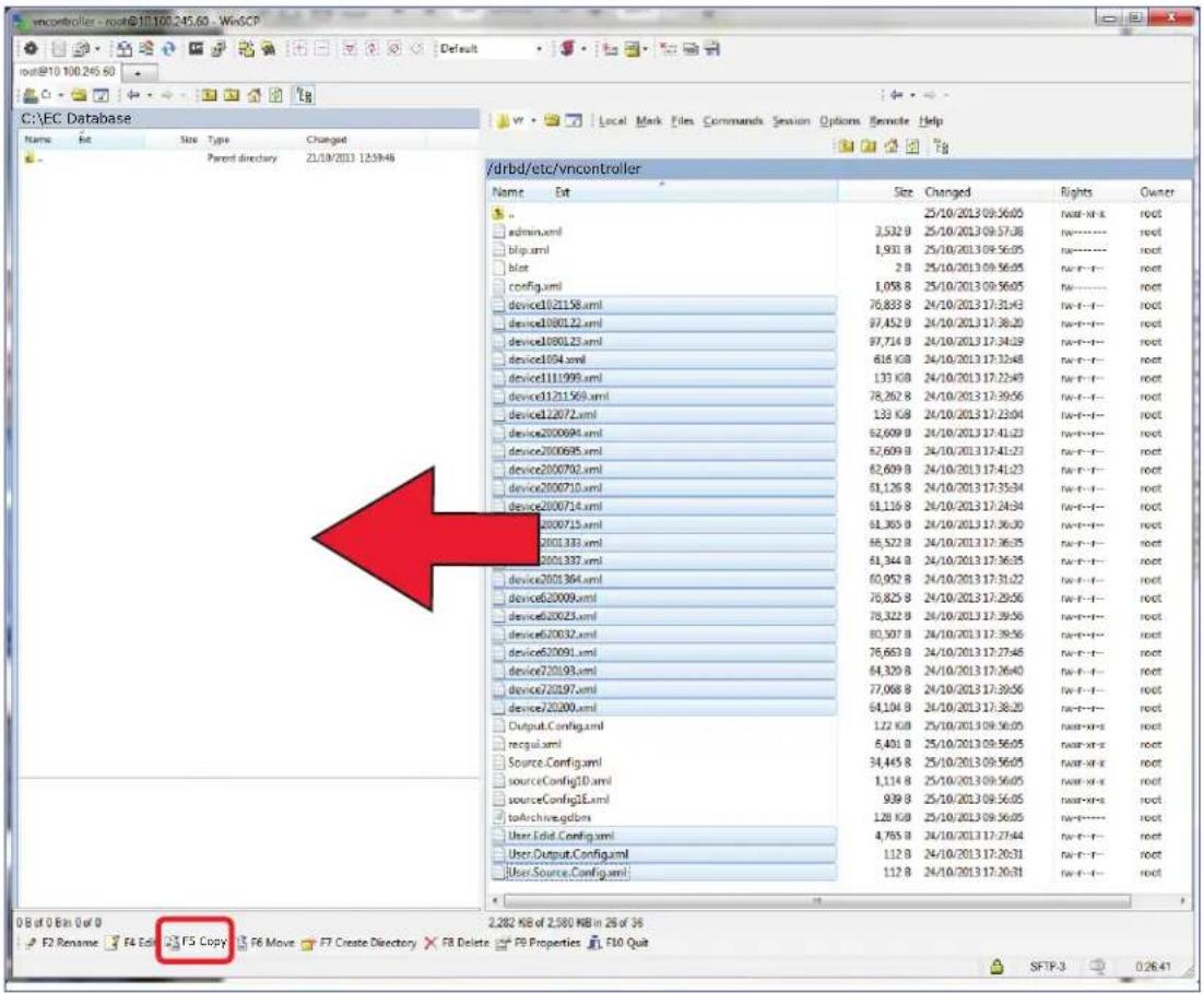
Figure 169. WinSCP Default Folders
- In the right pane, browse to the /drdb/var/lib/extron/matrix.hli folder (see figure 170).
- Copy the following files to the user documents folder (EC Database in the example below) in the left pane:
graph.gdbm
layout.gdbm

Figure 170. Copy Graph Files to PC User Folder
This completes the EC files backup.
Unpair the Controller Cluster
Before starting this procedure, go to www.extron.com/download and download the latest version of the VNM Enterprise Controller firmware. Note the file location you store it to.
The examples for this update procedure for the dual (redundant) VNM Enterprise Controllers use the following IP addresses:
Primary Redundant: 192.168.254.254
Secondary Redundant: 192.168.254.253
Cluster: 192.168.254.250
Copy your current IP addresses and substitute them in the appropriate update instructions.
See Configuring Dual Enterprise Controllers as the System Controller on page 165 for information on changing the IP address of the controllers, and Accessing the Web-based User Interface on page 11 for information on how to login.
-
Using a web browser, navigate to the web-based user interface by entering the Cluster IP address of the VNM Enterprise Controller pair.
-
Click the Configuration tab (see figure 171, ①).
The Configuration page opens.

Figure 171. Configuration Page — Cluster Controller
-
Click the Cluster link (②).
-
Click Unpair (③).
Update the Redundant Secondary Controller
- When Unpair is complete, use a new browser window or tab to log on to the redundant secondary controller, in this example 192.168.254.253.
- Select the Configuration tab (see figure 172, ①).

Figure 172. Configuration Page — Redundant Secondary Controller
- Click the Upgrade link (②).
- Click Browse (③). Use the file browser to navigate to the firmware file location. Select the file and click Open. The selected file location is now in the Package: field.
- Click Upgrade, ( 4).
Update the Primary Controller
- When the redundant controller upgrade completes, in a new browser window or tab, enter the IP address of the Primary VNM Enterprise Controller, in this example 192.168.254.254.
- Click the Configuration tab (see figure 173, ①).
The Configuration page opens.

Figure 173. Configuration Page — Primary Controller Configuration Page
- Click the Upgrade link in the left panel (see figure 173, ② on the previous page).
- Click Browse (3), and use the file browser to navigate to the firmware file location. Select the file and click Open.
- Click Upgrade, ( 4 ).
Pair the Controllers
- When the primary controller upgrade completes, click the Configuration tab (if the tab is not open).
The Configuration page opens (see figure 174, ①).

Figure 174. Configuration Page — Primary Controller Pairing
- Click the Cluster link (②).
- Click Pair (③).
- Click Apply Changes ( 4 ).
Note the Cluster IP Address, in this example: 192.168.254.250.
Restore the Device Configuration and Presets Files
When the pairing process is complete, the device and presets files can be restored.
- Reconnect WinSCP to the Enterprise Controller Cluster IP. Open WinSCP and create a connection with the following parameters (see figure 175):
File Protocol = SFTP
Host Name = The Cluster IP address of the
upgraded Enterprise Controller system
(192.168.254.250).
Port Number = 22
User Name = root
Password = Extron2010
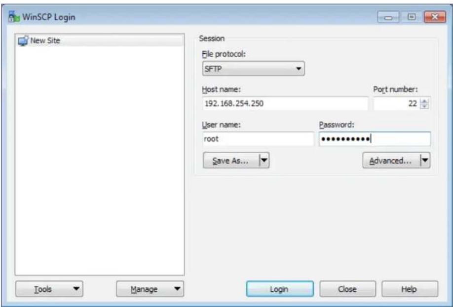
Figure 175. WinSCP Login Screen
- When configuration is completed, click Login.
WinSCP connects to the Enterprise Controller Cluster and opens the following dialog:

Figure 176. WinSCP Browser
The left pane defaults to the connected PC user documents folder. The right pane defaults to the Enterprise Controller cluster root directory.
-
In the left pane, navigate to the folder containing the previously saved XML files (see figure 177).
-
In the right pane, navigate to the server location:
- /drdb/etc/vncontroller
- From the the left pane, copy the following files to the server location (see figure 177).
• devicexxxxxx.xml (all .xml files that begin with "device")
- User.Edid.Config.xml
- User.Output.Config.xml
- User.Source.Config.xml

Figure 177. Copy Files to Enterprise Controller
- After the files are copied, set the file permissions on the copied files to "rw-r--r--".
a. In the right pane, select (highlight) all of the copied files.
b.
![device10101010.xml, .. Properties Common Checksum 27 files Location: /drbd/etc/incontroller Size: 2,461 KB (2,520, 111 B) Group: Owner: root [0] Permissions: Owner R W X Set UID Group R W X Set GID Others R W X Sticky bit Optel: 0644 OK Cancel Help](/content/2026/06/1249824/images/688a507ee200bb8bb447e76f20060575a1e05bfee321673e687e887f40fba7e1.jpg)
Figure 178. Change File Properties
c. In the Permissions panel, enter 0644 in the Octal: field.
d. Click OK to close the dialog.
- In the right pane, browse to the following folder (see figure 179):
/drdb/var.lib/extron/matrix.hli.
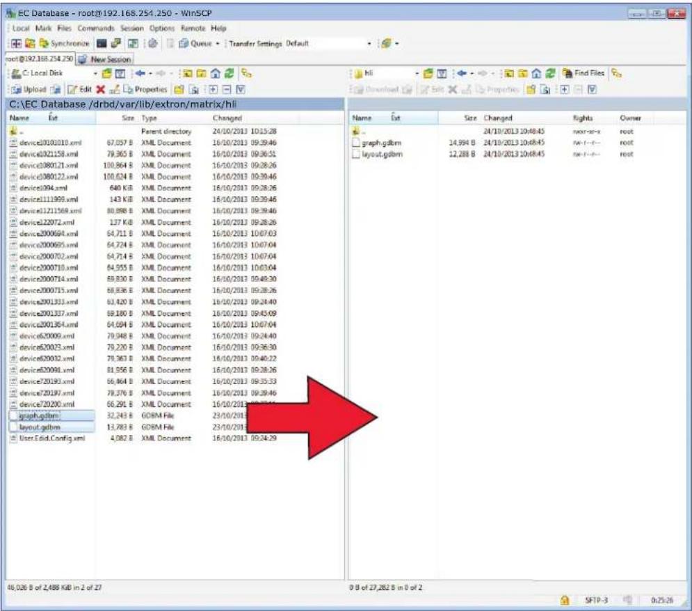
Figure 179. Copy Graph and Layout Files to Enterprise Controller
-
In the left pane, copy the following files to the right pane (see figure 179 on the previous page):
-
graph.gdbm
-
layout.gdbm
-
After copying the files, in the right pane, select, then
graph.gdbm, and set the file permissions to "rw-rw-rw-" (0666), (see step 6 on the previous page). -
Click OK to close the dialog.
- In the right pane, select, then
layout.gdbm and set the file permissions to "rwxr--r--" (∅744), (see step 6 on the previous page). - Click OK to close the dialog.
- Close or exit the WinSCP application.
This completes the EC files restore and the firmware upgrade.
Remove power from both Enterprise Controllers.
Reapply power. When the system boots, the new firmware is installed and the system returns to its previous operational state.
VN-Matrix Product Variants
The VNM Enterprise Controller is used with other products in the VN-Matrix range. The preceding sections of this user guide deal specifically with the configuration of the VNM Enterprise Controller with examples based on VN-Matrix systems that use VN-Matrix devices.
This section of the user guide provides information on the configuration and control of the other VN-Matrix Enterprise Controller variants and their operation with the VNM Enterprise Controller.
The following topics are covered in this section:
• VNM Enterprise Controller with CompactFlash Overview
• Installing and Configuring the CompactFlash Replacement Card
VNM Enterprise Controller with CompactFlash Overview
The VNM Enterprise Controller is available with an installed CompactFlash (CF) card. This card replaces the internal hard drive of the VNM Enterprise Controller. The CompactFlash VNM Enterprise Controller operates in the same way as the hard drive VNM Enterprise Controller and provides a removable operating system drive for secure operation in critical applications. The CompactFlash card is installed on the front panel of the VNM Enterprise Controller where the CD/DVD drive is located.
The CompactFlash card can be replaced, if necessary (see Installing and Configuring the CompactFlash Replacement Card below for information).
Installing and Configuring the CompactFlash Replacement Card
This section details the basic information needed to replace and configure an existing VNM Enterprise Controller CompactFlash card.
The replacement CF card is pre-configured with the following settings.
IP address: 192.168.254.254
Username: admin
Password:
Obtain the Configuration Settings of the VNM Enterprise Controller
Before replacing the VNM Enterprise Controller CF card, use the following steps to collect information about the current system configuration. The collected information should be copied and pasted into a text program (for example, Notepad).
ATTENTION:
- The licensing information must be written accurately. Copying incorrect data to the replacement CF card results in a non-functional unit.
-
L'information concernant l'octroi de licences doit être écrit avec précision. Le fait de copier des données incorrectes sur la carte CF de remplacement donne lieu à une unité non fonctionnelle.
-
Ensure the VNM Enterprise Controller has a CF card installed.
- Power on the VNM Enterprise Controller.
- Configure the network settings of a control PC so that it is compatible with the VN-Matrix network. Connect the control PC to the VN-Matrix network.
- Open a web browser on the control PC and type in the IP address of the VNM Enterprise Controller in the address bar (the default address is http://192.168.254.254). The login page opens (see figure 180).
Extron Electronics Matrix Enterprise Controller

Figure 180. VNM Enterprise Controller Login Page
- Enter the appropriate username and password.
NOTE: The default username is admin. By default, no password is required. These entries are case sensitive.
-
Click Login or press
. The Devices page opens (see About the Devices Page on page 36). -
From the Devices page, click the Configuration tab.
The Configuration page opens (see figure 181, ①).

Figure 181. Configuration Page
-
Click the System Config link (②).
-
In the Controllers field click on the IP address of this VNM Enterprise Controller (③).
-
Click License (4).
The Controller License Management dialog opens.

- Copy the values from the Options, Checksum, and Serial Number fields.
ATTENTION:
NOTE: The replacement CF card must be programmed with the correct operating system and VNM Enterprise Controller application files. Only use CF cards supplied by Extron.
- Power down the VNM Enterprise Controller and remove the front cover plate from the CF drive (see Front Panel Features on page 7).
- Eject the CF card from the CF drive and insert the replacement CF card.
- Replace the CF drive front cover plate.
Configure the Settings of the VNM Enterprise Controller
After the CF card is replaced, the VNM Enterprise Controller is returned to its default configuration settings and must be configured using the settings obtained in Obtain the Configuration Settings of the VNM Enterprise Controller on page 195.
Use the following procedures to configure the new CF card.
Set the serial number
- Connect a mouse, keyboard, and monitor to the VNM Enterprise Controller (see Rear Panel Features on page 9).
- Power on the VNM Enterprise Controller.
- When fully booted up, log into the VNM Enterprise Controller.
NOTE: The default username is root. The default password is Extron2010. These entries are case sensitive.
- At the prompt [root@singleton \~]#
- Type cd scripts
- Press
- At the prompt [root@singleton scripts]#
- Type ./set_serial.sh xxxxxxx where xxxxxx is the serial number of the VNM Enterprise Controller saved in step 11 of Obtain the Configuration Settings of the VNM Enterprise Controller on page 195.
- Press
- At the prompt [root@singleton \~]#
- Type reboot
- Press
The VNM Enterprise Controller reboots.
License configuration
- After the VNM Enterprise Controller has rebooted, configure the network settings of a control PC so that it is compatible with the VN-Matrix network. Connect the control PC to the VN-Matrix network.
NOTE: The control PC must use an IP address within 192.168.254.2 to 192.168.254.253 and a subnet mask of 255.255.255.0.
-
Open a web browser on the control PC and type the IP address of the VNM Enterprise Controller in the address bar (the default address is http://192.168.254.254). The login page opens in the browser.
-
Enter the default username and password.
NOTE: The default username is admin. By default, no password is required. These entries are case sensitive.
- Click Login or press
.
The Devices page opens.
- Click the Configuration tab (see figure 182, ①).
The Configuration page opens.

Figure 182. Configuration Page
-
Click the System Config link (②).
-
In the Controllers field, click the Add button (③).
The Peer Controller Address dialog box opens.
-
Enter the IP address of this VNM Enterprise Controller and click OK.
-
Click Apply Changes (4) to save the settings.

-
In the Controllers field (5), select the IP address of this VNM Enterprise Controller.
-
Click License (6).
The Controller License Management dialog box opens (see figure 183).
- Enter the information previously saved (see Obtain the Configuration Settings of the VNM Enterprise Controller on page 195) into the Options, Checksum, and Serial Number fields and click Update License.
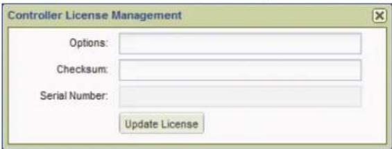
Figure 183. Controller License Management Dialog
ATTENTION:
NOTE: After clicking Update License, there is no feedback provided to show that the license information has been accepted.
- To check the license information, restart the VNM Enterprise Controller. Reconnect to the VNM Enterprise Controller by opening a web browser on the control PC and view the license information in the Controller License Management dialog box.
NOTE: The information in the Controller License Management dialog box takes several seconds to appear after the VNM Enterprise Controller has rebooted. - If the information does not appear, close the dialog box, wait for ten seconds and retry. - If the information is still not present, enter the serial number and license data again.
The VNM Enterprise Controller can now be configured for operation with the VN-Matrix system (see Advanced Controller Configuration on page 19).
Browser Configuration
This section provides information on configuring the following web browsers:
- Microsoft ^ Internet Explorer ^ (version 7 or above)
- Mozilla Firefox (version 1.3 or above)
Microsoft Internet Explorer (version 7 or above)
- Open Internet Explorer and select Tools > Internet Options. The Internet Options dialog opens (see figure 184).
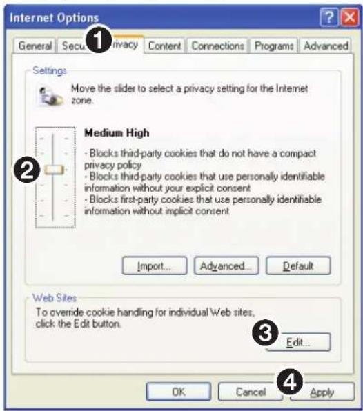
Figure 184. Internet Options
- To enable cookies, select the Privacy tab (①) and (if required) adjust the slider control (②) to set the required security level. VN-Matrix systems operate correctly using security that does not exceed the Medium High setting.
NOTE: Setting the security slider to block all cookies prevents the VN-Matrix web interface from operating.
TIP: If a high security level is required, click on the Edit button (③) and allow the VN-Matrix web interface to use cookies (see figure 185 on the next page).
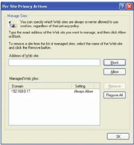
Figure 185. Per Site Internet Options
- To enable JavaScript, select the Security tab (see figure 186, ①).
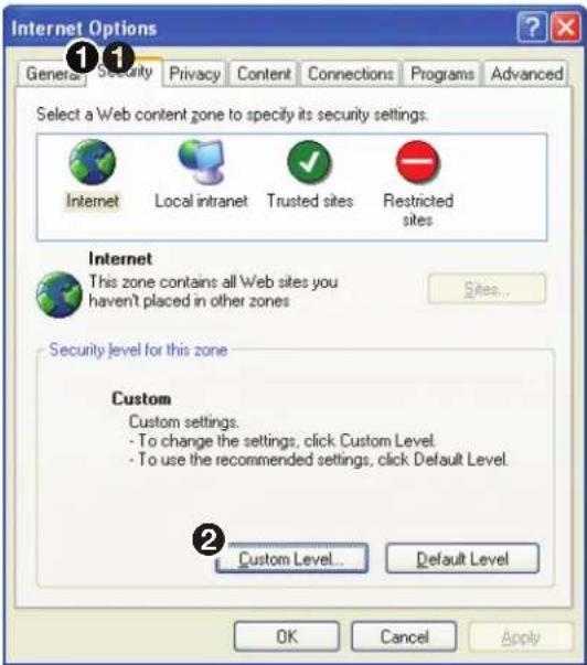
Figure 186. Security Options
- Click Custom Level (②).
The Security Settings dialog box opens (see figure 187).
- Scroll down to the Scripting setting and under Active scripting, select Enable (1).
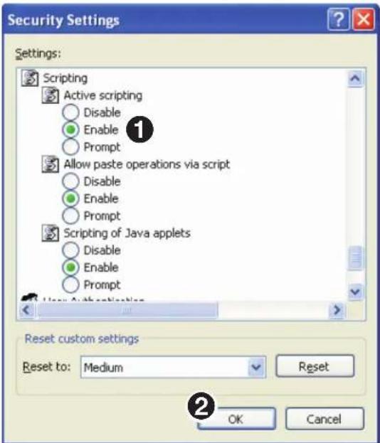
Figure 187. Custom Level Security Options
- Click OK (②) on both dialog boxes to save the new settings and close the dialogs.
Mozilla Firefox (version 1.3 or above)
- Open Mozilla Firefox and select Edit > Preferences. The Preferences dialog box opens (see figure 188).
- To enable cookies, go to the Privacy & Security category and choose Cookies (see figure 188, ①).

Figure 188. Cookie Preferences
-
Ensure that either the Enable all cookies or Enable cookies for the originating web site only (2) option is selected.
-
To enable JavaScript, go to the Advanced category and choose Scripts & Plugins (see figure 189, ①).

Figure 189. Scripts and Plugins Preferences
-
Ensure that the Enable JavaScript for Navigator (②) option is selected.
-
Click OK (③) to close the dialog box and save the settings.
Reference Information
This section provides information about:
- Default Factory Settings
• VN-Matrix System Port Usage - Mounting
• HLI Command Overview
• HLI Command Examples - General Commands
- Preset Commands
Default Factory Settings
| Network settings (ETH0) IP address | 192.168.254.254 | |
| Subnet mask | ||
| Gateway address | ||
VN-Matrix System Port Usage
The VN-Matrix system uses a variety of network port numbers for streaming and inter-communication functions. Just as the universal "telnet" function typically uses TCP port number 23, VN-Matrix systems use specific port numbers for operation.
The table on the following page lists the port numbers used by the VN-Matrix series products. The port numbers are, in most cases, for the sender. Port numbers used for receiving are less important in regards to security.
When configuring a network, make sure it allows traffic on the ports required for your given application. The ports highlighted in yellow accommodate most simple applications.
| Port Transport Usage | ||
| 69 UDP TFTP Server, for firmware upgrades. | ||
| 80 TCP HTTP data for communication between the web browser and the Enterprise Controller. Value is user definable; the default is 80. | ||
| 554 TCP Real-time streaming protocol (RTSP) server. | ||
| 5432 UDP Enterprise Controller outgoing and incoming control messages used on the device acting as controller to communicate with other VN-Matrix devices. Value is user definable; the default is 5432. | ||
| 5555 TCP Old XML interface and old VN-Matrix recorder software application. No longer used. | ||
| 9998 TCP Telnet Command and Line Interface (CLI) messages to the controller used for sending text-based control commands. | ||
| 9999 TCP Deprecated: Old remote control server, replaced by CLI (port 9998). | ||
| 23 TCP Telnet (can be disabled). | ||
| 161 UDP Simple network management protocol (SNMP) used for alarm access. | ||
| 199 TCP Simple network management protocol (SNMP) used for alarm access. | ||
| 4002 TCP Source stream information, used to telnet to a VN-Matrix decoder to view information about the source it is decoding. | ||
| 5002 TCP Serial port bidirectional protocol (not data channel streaming). | ||
| 6666 TCP Keyboard and mouse forwarding. | ||
| 7777 UDP Upgrade daemon, local access only. | ||
| 8000-8098 (even) | UDP RTP unicast or RTP multicast audio, video, whiteboard, and data streams used as the port number of the destination (receiver). The controller selects a port number, starting at 8000. | |
| 8001-8099 (odd) | UDP RTCP channel for audio, video, whiteboard, and data streams used as the port number of the destination (receiver). Grouped with the even-numbered stream (8000 with 8001, 8002 with 8003, and so on). | |
| 8000 TCP Video streams, used as the port number of the source (sender). | ||
| 8100 TCP Audio streams, used as the port number of the source (sender). | ||
| 8200 TCP Whiteboard streams, used as the port number of the source (sender). | ||
| 8201 TCP Data streams, used as the port number of the source (sender). | ||
| 9000 TCP HSI interface when using ThorDebug. | ||
| 9001 UDP VN-Matrix outgoing and incoming control messages. Communicates with port 5432 (or the user defined port number) on the Enterprise Controller. | ||
| 9002 UDP Default port for collecting UDP traffic for data transport. Value is user-definable. | ||
| 9996 TCP HLI server port. | ||
| 9997 TCP Annotation server port. | ||
Mounting
Rack Installation
This section provides information on installing the controller into a rack cabinet. Rack installation requires the use of the optional rack mount kit.
There are a variety of rack cabinets on the market, which may mean the assembly procedure will differ slightly. If necessary, refer to the instructions that came with the rack cabinet to complete the rack installation.
UL Guidelines for Rack Mounting
The following Underwriters Laboratories (UL) guidelines are relevant to the safe installation of these products in a rack:
- Elevated operating ambient temperature — If the unit is installed in a closed or multi-unit rack assembly, the operating ambient temperature of the rack environment may be greater than room ambient temperature. Therefore, install the equipment in an environment compatible with the maximum ambient temperature (TMA: +122 °F, +50 °C) specified by Extron.
- Reduced air flow — Install the equipment in the rack so that the equipment gets adequate air flow for safe operation.
- Mechanical loading — Mount the equipment in the rack so that uneven mechanical loading does not create a hazardous condition.
- Circuit overloading — Connect the equipment to the supply circuit and consider the effect that circuit overloading might have on overcurrent protection and supply wiring. Consider the equipment nameplate ratings when addressing this concern.
- Reliable earthing (grounding) — Maintain reliable grounding of rack-mounted equipment. Pay particular attention to supply connections other than direct connections to the branch circuit (such as the use of power strips).
Basic Rack Mounting
The VNM Enterprise Controller comes with two rack mounting brackets, located on each side at the front of the chassis. To mount the controller, screw these brackets directly to the front of the rack using two screws for each bracket (see figure 190).

natural_image
Isometric technical diagram of a mechanical lifting or mounting structure with vertical supports and a central frame (no text or symbols)Figure 190. Basic Rack Installation
Rack Mounting Using Rack Rails
The supplied rack mount kit includes two rack rail assemblies. Each of these assemblies consist of three sections: an inner fixed rail that secures to the controller frame (see figure 191, A) an outer rack rail that secures directly to the rack (B), and two rail brackets (C) that also attach to the rack.
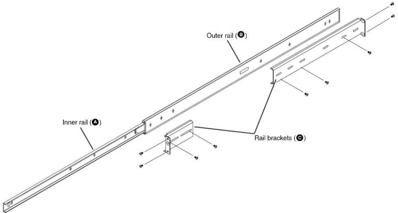
Figure 191. Identifying the Sections of the Rack Rails
To install the controller into a rack, follow the steps below.
- Remove the inner rail (A) by pulling it out as far as possible. A locking tab prevents the rail from pulling all the way out, and makes a clicking noise when the rail is fully extended. Depress the locking tab to pull the inner rail completely out. Do this for both assemblies (one for each side).
NOTE: Each rail has a locking tab serving two functions. The first is to lock the controller in place when installed and pushed fully into the rack. Secondly, the tabs lock the controller in place when fully extended from the rack to prevent pulling the controller completely out of the rack.
- Align each inner rail (A) to the screw holes located on the left and right side of the controller. Secure the rails to the sides of the controller frame (see figure 192).
NOTE: The two inner rail assemblies are left and right specific.

Figure 192. Installing the Rails onto the Controller Frame
-
Determine where the controller is located within the rack (see Mounting on page 206).
-
Position the front and rear rail brackets at the desired location in the rack (see figure 193). Screw the rail brackets securely to the rack. Attach the remaining rail brackets to the other side of the rack, making sure both sets are at the same height.
NOTE: The smaller rail bracket is positioned at the front of the rack and the larger rail bracket is positioned at the back of the rack.

Figure 193. Install Rail Brackets (©)
- Secure the outer rails to the rail brackets (see figure 194).
NOTE: The two outer rails are left and right specific.

Figure 194. Installing the Outer Rail (B) to the Rail Brackets (C)
- Line up the inner rails on the controller with the outer rails on the rack. Gently slide the controller into the outer rails of the rack (see figure 195). Depress the locking tabs, if necessary, when sliding the controller into the outer rails.

natural_image
Isometric line drawing of a vertical storage or lifting platform with metal racks and a front panel, no text or symbols present.Figure 195. Installing the Controller into a Rack
-
Connect the necessary devices to the controller (see Front Panel Features on page 7 and Rear Panel Features on page 9).
-
When the controller is pushed completely into the rack, the locking tabs make a clicking sound. If necessary, secure the front mounting brackets (located on each side at the front of the chassis) to the rack to keep the controller in a fixed position.
HLI Command Overview
The format of an HLI command is shown below.
Command Structure
command argument1 argument2 [optional argument1] [optional argument2]...
NOTE: The number of arguments, both required and optional, depends on the command.
Each command has a defined structure. The HLI command must begin the string but additional commands can follow that include arguments, parameters, and other variables. Each command ends with an
In the commands and examples that follow, HLI commands are represented in fixed fonts. Identifiers, variables, arguments, and parameters are in slanted fonts.
NOTES:
- Text inside brackets [example text] represent optional command arguments. Do not include the brackets when entering the command.
- A response is returned each time an HLI command is properly sent. The text depends on the type of command. If the command is formatted correctly and accepted, the reply is "okay" unless otherwise stated.
Devices can be identified in one of three ways:
- IP Address – The IP address of the target device.
- Device Name – The name of the device as assigned by the user.
- Device ID – A unique number identifying the target device.
NOTE: The device ID is found on the product sticker located on the device, or in the Device List of the Enterprise Controller. The ID numbers used in the following examples have been simplified for the HLI command structure examples and do not represent actual device IDs.
HLI Command Examples
The HLI command examples that follow refer to a VN-Matrix system consisting of the devices shown in figure 196. The devices are connected using their Ethernet ports with corresponding device ID, IP address, and device names.

flowchart
graph TD
    A["Browser Based Control PC"] --> B["VNM 200 or 225 Series Codec (Source)"]
    A --> C["VNM Enterprise Controller"]
    A --> D["VNM 200 or 225 Series Codec (Display)"]
    A --> E["VNM 200 or 225 Series Codec (Display)"]
    A --> F["VNM 300 Series Codec"]
    A --> G["VNS 104"]
    A --> H["VNR 100"]
    A --> I["VNM Matrix Recorder"]
    B --> J["Device ID: 20001"]
    B --> K["IP Address: 192.168.0.21"]
    B --> L["Device Name: 200_Device1"]
    C --> M["Device ID: 20002"]
    C --> N["IP Address: 192.168.0.22"]
    C --> O["Device Name: 200_Device2"]
    D --> P["Device ID: 30001"]
    D --> Q["IP Address: 192.168.0.31"]
    D --> R["Device Name: 300_Device1"]
    E --> S["Device ID: 30002"]
    E --> T["IP Address: 192.168.0.32"]
    E --> U["Device Name: 300_Device2"]
    F --> V["Device ID: 30003"]
    F --> W["IP Address: 192.168.0.23"]
    F --> X["Device Name: 200_Device3"]
    G --> Y["Device ID: 40001"]
    G --> Z["IP Address: 192.168.0.41"]
    G --> AA["Device Name: 104_Device1"]
    H --> AB["Device ID: 50001"]
    H --> AC["IP Address: 192.168.0.51"]
    H --> AD["Device Name: 5Ch_Device1"]
Figure 196. Basic Application Diagram for HLI Command Control
Not shown: VNM 250.
General Commands
General commands are structured using both fixed commands and variables. In the following pages, fixed commands are in command fonts that identify the HLI commands. Variables that represent the device identifier, argument, or parameter values are in italic fonts.
analogOutputEnable
The analogOutputEnable command enables or disables audio for devices running the VNS 104 software decoder. The command is sent to window 4, the VNS 104 audio channel.
NOTE: This command uses zero-based window numbering. Channel numbers 0 to 3 refer to the top-left, top-right, bottom-left and bottom-right positions respectively. Channel number 4 selects the audio channel.
Command line structure — analogOutputEnable
| set device identifier swdecoder window 4 analogOutputEnable enablemode← |
Available parameters and arguments for this command are:
| Parameter Argument Description | ||
| identifier | Device ID, IP address or Device name | |
| enablemode enable | or disable | Mutes or unmutes the audio. |
For the following examples:
VNS 104: Device name = 104_Device1, Device ID = 40001, IP address = 192.168.0.41
Example 1 - Enable (unmute) audio on a VNS 104 using device name.
set device 104_Device1 swdecoder window 4 analogOutputEnable enable←
Example 2 - Disable (mute) audio on a VNS 104 using device ID
set device 40001 swdecoder window 4 analogOutputEnable disable
analogOutputMute
The analogueOutputMute command mutes or un-mutes the audio channel for devices running the VNS 104 software decoder. The command is sent to window 4, the VNS 104 audio channel.
NOTE: This command uses zero-based window numbering. Channel numbers 0 to 3 refer to the top-left, top-right, bottom-left and bottom-right positions respectively. Channel number 4 selects the audio channel.
Command line structure
| set device identifier swdecoder window 4 analogOutputMute mutemode← |
Available parameters and arguments for this command are:
| Parameter Argument Description | ||
| identifier | Device ID, IP address or Device name | |
| mutemode | normal or mute | mutes or unmutes the audio. |
For the following examples:
VNS 104: Name = 104_Device1, ID = 40001, IP = 192.168.0.41
Example 1 - Mute the audio on a VNS 104 using the device name.
set device 104_Device1 swdecoder window 4 analogOutputMute mute
Example 2 - Unmute audio on a VNS 104 using the device ID.
set device 40001 swdecoder window 4 analogOutputMute normal
analogOutputSetLevel
The analogueOutputSetLevel command sets the level of the audio channel on VNS 104 devices. The command is sent to window 4, the VNS 104 audio channel.
NOTE: This command uses zero-based window numbering. Channel numbers 0 to 3 refer to the top-left, top-right, bottom-left and bottom-right positions respectively. Channel number 4 selects the audio channel.
Command line structure
set device identifier swdecoder window 4 analogOutputSetLevel level
Available parameters and arguments for this command are:
| Parameter Argument Description | ||
| identifier | Device ID, IP address, or device name | |
| level integer between -70 and 12 | ||
For the following examples:
VNS 104: Name = 104_Device1, ID = 40001, IP = 192.168.0.41
Example 1 - Set the audio level on a VNS 104 to a value of +6 using the device name. set device 104_Device1 swdecoder window 4 analogOutputSetLevel 6
Example 2 - Set the audio level on a VNS 104 to a value of -36 using a device ID: set device 40001 swdecoder window 4 analogOutputSetLevel -36
connect
The connect command switches streams from a source device to a destination device. This command manages the individual parameters required to configure a VN-Matrix stream, including the provisioning of the VN-Matrix devices, to their required state.
Command line structure
connect source:n destination:n [optional parameters]
Available parameters and arguments for this command are:
| Parameter Argument Description | ||
| source:n | Device ID, IP address, or Device name followed by an optional channel number :n | |
| destination | Device ID, IP address, or Device name followed by an optional channel number :n | |
Additional stream types (audio, data, whiteboard) can be specified as well as the network transport protocol (TCP, UDP or multicast) using optional parameters. Unless otherwise specified, the current global values as defined in the System Controller are used.
The channel designator :n provides support for channel-based devices such as the VN Recorder and VNS 104.
If either the source or destination devices are a VNM Recorder or VNR 100, the connect command is also used to select or create a directory for recording or to load an existing directory for playback.
If the command and parameters are correctly entered and accepted by the controller the return is: "okay"
Additional optional parameters and arguments for this command are:
| Parameter Arguments Description | ||
| source 50001:1 | The serial number (ID) of the source device followed by the channel number (if applicable) | |
| 192.168.0.51:1 | The IP address of the source device followed by the channel number (if applicable) | |
| VN_Recorder:1 | The user-defined name of the source device followed by the channel number (if applicable) | |
| none | Clears all connections to this source | |
| destination 40001:1 | The serial number (ID) of the display device followed by the channel number (if applicable) | |
| The IP address of the display device followed by the channel number (if applicable) | ||
| The user-defined name of the display device followed by the channel number (if applicable) | ||
| none | ||
| streams a | Audio (excluding VNM 3xx series devices) | |
| a2 | Program and return audio (VNM 250 only) | |
| n | ANC (VNM 3xx series audio) | |
| v | Video | |
| w | Whiteboard (specially licensed feature) | |
| d | Data (specially licensed feature) | |
| r | Row FEC (VNM 3xx only) | |
| c | Column FEC (VNM 3xx only) | |
| Example: streams=n,v,d | ANC, video and data | |
| program_audio_source | 25002 | The serial number (ID) of the device (VNE 250 only) |
| 192.168.0.252 | The IP address of the device (VNE 250 only) | |
| 250_Encoder_2 | The user-defined name of the device (VNE 250 only) | |
| transport | unicast | UDP point to point connection |
| tcp | TCP connection using IP address of source and destination devices | |
| multicast | Multicast - addresses managed by Enterprise Controller settings | |
| Example: transport=unicast | Unicast mode | |
| name | name=dir1Example:name=dir1:Matrix1 | Specifies directory name "dir1" for recordingSpecifies directory name "dir1" with filename "Matrix1" for recording |
| directory directory=dir1 | Specifies directory name "dir1" for playback | |
| filename | filename=Matrix1 | Specifies filename "Matrix1" for playback |
| timestamp | timestamp="duplicate1" | Specifies a user-defined text string appended to a new directory if the directory name exists. For example, a duplicate Matrix1 directory becomes Matrix_1-duplicate1. If the timestamp parameter is not included, duplicate directories are automatically appended with the Controller date and time in the form YYYY-MM-DD-hh-mm-ss.Example:Matrix_1-2013-01-19-12-19-24 |
VNM 200/225 Device Examples
For the VNM 200/225 device examples:
2xx Device1: Name = 200_Device1, ID = 20001, IP = 192.168.0.21
2xx Device2: Name = 200_Device2, ID = 20002, IP = 192.168.0.22
Example 1 - Connect Device1 to Device2 using the device IDs.
connect 20001 20002
Example 2 - Connect Device1 to Device2 using the device names.
connect 200_Device1 200_Device2
Example 3 - Connect Device1 to Device2 using the IP addresses.
connect 192.168.0.21 192.168.0.22
Example 4 - Connect Device1 to Device2 using a combination of device ID and IP address.
connect 20001 192.168.0.22
Example 5 - Connect Device1 to Device2 with audio, video, and data streams.
connect 20001 20002 streams=a,v,d
Example 6 - Connect Device1 to Device2 in multicast mode, with audio, video, and data streams.
connect 20001 20002 transport=multicast streams=a,v,d
Example 7 - Break connections to Device1 (where Device1 is a source).
connect 20001 none ←
Example 8 - Break connections to Device2 (where Device2 is a display).
connect none 20002
VNM 250 Device Examples
For the VNM 250 device examples:
VNE 250 Encoder1: Name = 250_Encoder1, ID = 25001, IP = 192.168.0.251
VNE 250 Encoder2: Name = 250_Encoder2, ID = 25002, IP = 192.168.0.252
VND 250 Decoder1: Name = 250_Decoder1, ID = 25003, IP = 192.168.0.253
Example 1 - Connect Encoder1 to Decoder1 using the device IDs.
connect 25001 25003
Example 2 - Connect Encoder1 to Decoder1 using the device names.
connect 250_Encoder1 250_Decoder1
Example 3 - Connect Encoder1 to Decoder1 using the device IP addresses.
connect 192.168.0.251 192.168.0.253
Example 4 - Connect Encoder1 to Decoder1 using a combination of device ID and IP address.
connect 25001 192.168.0.253
Example 5 - Connect Encoder1 to Decoder1 with audio, video, and data streams.
connect 25001 25003 streams=a,v,d
Example 6 - Connect Encoder1 to Decoder1 in multicast mode, with audio, video, and data streams.
connect 25001 25003 transport=multicast streams=v,d
Example 7 - Connect Encoder1 to Decoder1 with breakaway audio from Encoder2. connect 25001 25003 streams=v, a program_audio_source=25002
Example 8 - Connect Encoder1 to Decoder1 with program and return audio (Decoder1 back to Encoder1). connect 25001 25003 streams=v, a2
Example 9 - Break connections to Encoder1. connect 25001 none ←
Example 10 - Break connections to Decoder1. connect none 25003
VNM 3xx Devices
For the VNM 3xx device examples:
3xx Device1: Name = 300_Device1, ID = 30001, IP = 192.168.0.31
3xx Device2: Name = 300_Device2, ID = 30002, IP = 192.168.0.32
Example 1 - Connect Device1 to Device2 using device ID. connect 30001 30002
Example 2 - Connect Device1 to Device2 using device names. connect 300_Device1 300_Device2
Example 3 - Connecting Device1 to Device2 using IP addresses. connect 192.168.0.31 192.168.0.32
Example 4 - Connecting Device1 to Device2 using a combination of device ID and IP address. connect 30001 192.168.0.32
Example 5 - Connect Device1 to Device2 with audio, video, FEC row, and FEC column streams. connect 30001 30002 streams=n, v, r, c
Example 6 - Connect Device1 to Device2 in multicast mode, with video, FEC row, and FEC column streams. connect 30001 30002 transport=multicast streams=v,r,c
Example 7 - Break connections to Device1 (where Device1 is a source). connect 30001 none ←
Example 8 - Break connections to Device2 (where Device2 is a display). connect none 30002
VNS 104 Devices
For the VNS 104 device examples:
VNS 104: Name = 104_Device1, ID = 40001, IP = 192.168.0.41
VNM 2xx: Name = 200_Device1, ID = 20001, IP = 192.168.0.21
Example 1 - Connect VNM 2xx to VNS 104 top left quadrant using device IDs. connect 20001 40001:0
Example 2 - Connecting VNM 2xx to VNS 104 top left quadrant using device names. connect 200_Device1 104_Device1:0
Example 3 - Connect VNM 2xx to VNS 104 top left quadrant using IP addresses. connect 192.168.0.21 192.168.0.41:0
Example 4 - Connect VNM 2xx to VNS 104 using a combination of device ID and IP address. connect 20001 192.168.0.41:0
Example 5 - Connect VNM 2xx to VNS 104 bottom right quadrant. connect 20001 40001:3
Example 6 - Connect VNM 2xx video and audio only to VNS 104 bottom right quadrant. connect 20001 40001:3 streams=v, a ←
Example 7 - Connect VNM 2xx video and audio to VNS 104 bottom right quadrant in multicast mode. connect 20001 40001:3 streams=v, a transport=multicast
Example 8 - Break connection of the VNS 104 bottom left quadrant. connect none 40001:2
VNR 100 Devices
For the VNR 100 device examples:
VNR 100: Name = 100 Device1, ID = 10001, IP = 192.168.0.11
VNM 2xx: Name = 200_Device1, ID = 20001, IP = 192.168.0.21
Example 1 - Connect VNM 2xx (source) to VNR 100 (recorder) specifying a recording directory "dir1". connect 20001 10001 name=dir1
Example 2 - Connect VNM 2xx (source) to VNR 100 (recorder) specifying a recording directory "dir1" with a filename of "matrix". connect 20001 10001 name=dir1:matrix
Example 3 - Connect VNM 2xx (source) to VNR 100 (recorder) with video, audio, and data streams and specify a recording directory "dir1" with a filename of "matrix". connect 20001 10001 streams=a,v,d name=dir1:matrix
Example 4 - Connect VNM 2xx (source) audio, video, and data streams to VNR 100 (recorder) specifying a recording directory "dir1" with a filename of "matrix" and a custom duplicate directory suffix of "duplicate1". connect 20001 10001 streams=a,v,d name=dir1:matrix timestamp="duplicate1"
Example 5 - Connect VNM 2xx (source) video, audio, and data streams to VNR 100 (recorder) in multicast mode specifying a recording directory "dir1" with a filename of "matrix". connect 20001 10001 transport=multicast streams=a,v,d name=dir1:matrix
Example 6 - Connect VNR 100 (player) to VNM 2xx (display) specifying a filename "recording1" located in directory "dir1". connect 10001 20001 directory=dir1 filename=recording1
Example 7 - Connect VNR 100 (player) video and audio streams to VNM 2xx (display) in unicast mode specifying a filename "recording1" located in directory "dir1". connect 10001 20001 transport=unicast streams=v,a directory=dir1 filename=recording1
Example 8 - Break connections to the VNR 100 (recorder). connect none 10001
VNM Recorder (5 Channel) Devices
For the VNM Recorder device examples:
VNM Recorder: Name = 5ch_Device1, ID = 50001, IP = 192.168.0.51
VNM 2xx: Name = 200_Device1, ID = 20001, IP = 192.168.0.21
VNR 100: Name = 100_Device1, ID = 10001, IP = 192.168.0.11
Example 1 - Connect VNM 2xx (source) to VNM Recorder channel 2 specifying a recording directory "dir1".
connect 20001 50001:2 name=dir1
Example 2 - Connect VNM 2xx (source) to VNM Recorder channel 2 specifying a recording directory "dir1" with a filename of "matrix"
connect 20001 50001:2 name=dir1:matrix
Example 3 - Connect VNM 2xx (source) video, audio, and data streams to VNR 100 (recorder) specifying a recording directory "dir1" with a filename of "matrix".
connect 20001 10001 streams=a,v,d name=dir1:matrix
Example 4 - Connect VNM 2xx (source) video, audio, and data streams to VNM Recorder channel 2 specifying a recording directory "dir1" with a filename of "matrix" and a custom duplicate directory suffix of "duplicate1".
connect 20001 50001:2 streams=a,v,d name=dir1:matrix timestamp=duplicate1
Example 5 - Connect VNM 2xx (source) video, audio, and data streams to VNM Recorder channel 2 in multicast mode specifying a recording directory "dir1" with a filename of "matrix".
connect 20001 50001:2 transport=multicast streams=a,v,d
name=dir1:matrix
Example 6 - Connect VNM-Recorder (player) channel 3 to VNM 2xx (display) specifying a filename "rec1" located in directory "dir1".
connect 50001:3 20001 directory=dir1 filename=rec1
Example 7 - Connect VNM-Recorder (player) channel 3 video and audio streams to VNM 2xx (display) in unicast mode with a filename "rec1" located in directory "dir1".
connect 50001:3 20001 transport=unicast streams=v,a directory=dir1 filename=rec1
Example 8 - Break connections to VNM-Recorder channel 2.
connect none 50001:2
createdisplay
The createdisplay command sets a VN-Matrix Codec device to display mode (decoder). It disconnects existing connections before changing the device mode.
Command line structure
createdisplay device
device: Device name, device ID, or IP address.
For the following examples:
VNM 2xx: Name = 200_Device1, ID = 20001, IP = 192.168.0.21
VNM 3xx: Name = 300_Device2, ID = 30001, IP = 192.168.0.31
Example 1 - Set a VNM 2xx device to display mode using the IP address. createdisplay 192.168.0.21
Example 2 - Set a VNM 2xx device to display mode using the device name. createdisplay 200_Device1
Example 3 - Set a VNM 3xx device to display mode using the device ID. createdisplay 30001
createsource
The createsource command sets a VN-Matrix Codec device to source mode (encoder). It disconnects existing connections before changing the device mode.
Command line structure
createsource device
device: Device name, device ID, or IP address.
For the following examples:
VNM 2xx: Name = 200_Device1, ID = 20001, IP = 192.168.0.21
VNM 3xx: Name = 300_Device2, ID = 30001, IP = 192.168.0.31
Example 1 - Set a VNM 2xx device to source mode using the IP address. createsource 192.168.0.21
Example 2 - Set a VNM 2xx device to source mode using the device name. createsource 200_Device1
Example 3 - Set a VNM 3xx device to source mode using the device ID. createsource 30001
currentTime
The currentTime command returns the current system time of the VN-Matrix controller. It can be obtained from any active VN-Matrix device on the system excluding the VN-Matrix Enterprise Controller. The currentTime value is the reference point when setting future event start times (see play).
Command line structure
get device identifier currentTime
identifier: Device name, device ID, or IP address of VN-Matrix device (not the EC).
Return attributes:
currentTime: hh:mm:ss:uuuuuu
For the following examples:
2xx Device1: Name = 200_Device1, ID = 20001, IP = 192.168.0.21
Example 1 - Getting the VN-Matrix controller system time using the IP address as identifier.
get device 192.168.0.21 currentTime
Returns: "11:53:02.174478"
Example 2 - Getting the VN-Matrix controller system time using device name as identifier.
get device 200_Device1 currentTime
Returns: "11:53:02.174478"
deleteddevice
The deleted device command removes unused devices from the VN-Matrix system. Attempting to remove a device currently in use results in a fail code.
Command line structure
deleted device device
device: Device name, device ID, or IP address.
For the following examples:
2xx Device1: Name = 200_Device1, ID = 20001, IP = 192.168.0.21
2xx Device2: Name = 200_Device2, ID = 20002, IP = 192.168.0.22
Example 1 - Delete an unused 2xx device from the system.
deleteddevice 20001
Example 2 - Attempting to delete a 2xx device with active connections.
deleteddevice 20002
Returns: "fail: code=13, object in use"
disconnectall
The disconnectall command breaks all connections to all devices on the VN-Matrix controller.
Command line structure
disconnectall
Example 1 - Break all connections to all devices on a VN-Matrix controller.
disconnectall
getalarmlogs
The getalarmlogs command returns a list and details of alarms present on the VN-Matrix system.
| Command line structure |
| getalarmlogs |
Returned attributes for this command are:
| Attribute Value | Description | |
| severity | critical, warning, none A summary of the severity of the alarm. | |
| alarm_id | nnnExample: 232 | The associated ID number of the alarm. |
| controller | IP address: nnn.nnn.nnn.nnnExample: 192.168.0.254 | The IP address of the controller on which the alarm has been flagged. |
| device_type | Text stringExample: VNM Recorder | The type of device the alarm has been raised. |
| raisetime | Text string, dateExample: Wed, 06 Feb 201309:56:15 GMT | The time and date when the alarm condition was raised. |
| type | Text stringExample: 22 - Bad Device | The type code and description of the raised alarm. |
| serial | nnnnnExample: 50001 | The serial number (ID) of the device where the alarm has been raised. |
| name | Text stringExample: 5ch_Device1 | The name of the device where the alarm has been raised. |
Example 1 - Return a list of current alarms on the system.
getalarmlogs
Returns: [{"severity":"Critical","alarm_id":232,"controller":"192.168.0.254","device_type":"VNM Recorder","raisetime":"Wed,06Feb 2013 09:56:15 GMT","type":"22-Bad Device","serial":50001,"name":"5ch_Device1"}]
getcontrollers
The getcontrollers command returns a list of controller IP addresses associated with the VN-Matrix system.
| Command line structure |
| getcontrollers |
Example 1 - Return a list of controller IP addresses on the VN-Matrix system.
getcontrollers
Returns: ["192.168.0.254"]
getdevices
The getdevices command returns attributes and values for all devices connected to the VN-Matrix System Controller. Optional parameters can limit the attributes that are returned or can filter which devices return attributes.
| Command line structure |
| getdevices keys where order_by |
Available parameters and arguments for this command:
| Parameter Argument Description | ||
| keys | Attribute or Attribute1, Attribute2Example: keys="name,localp0" | Any attribute from the getdevices attribute table. Comma separated list of desired attributes. |
| where | Attribute Any attribute from the getdevices attribute table. | |
| = Equals | ||
| <> Does not equal | ||
| like ‘so%’ Starts with string ‘so’ | ||
| like ‘%urce’ Ends with string ‘urce’ | ||
| like ‘%our%’ Contains string ‘our’ | ||
| and Logical and | ||
| or Logical or | ||
| Example: where="type='source'" Example: where="type='source' and source_status='Active'" | ||
| order_by | Attribute: | Any attribute from the getdevices attribute table. |
| ASC Sort in ascending order. | ||
| DESC Sort in descending order. | ||
| Example: order_by="localp0 ASC" | ||
Attributes for the command parameter argument (all are returned by default):
| Attribute Value | Description | |
| controllerIp | nnn.nnn.nnn.nnnExample: 192.168.0.254 | IP address of the controller for this device. |
| curver | ver(major.minor.build)Example: ver5.2.0 | Current firmware version of the device. |
| device_id | Serial number: channelExample: 50001:2 | The unique serial number of the device,followed by the channel number if applicable(VNM Recorder and VNS 104). |
| device_type | Text stringExample: VNC 200 DVI-AD | Hardware type associated with the device. |
| dstIp | nnn.nnn.nnn.nnn :nnnnExample: 192.168.0.23:8000 | Stream destination IP address and port number. |
| localIp0 | nnn.nnn.nnn.nnnExample: 192.168.0.51 | IP address of Ethernet port 0 on the device. |
| mode | enable/disable/standbyExample: enable | The current operating mode of the device. |
| name | Name: channelExample: 5ch_Device1:2 | The user-defined name of the device followed bythe channel number if applicable (VNM Recorderand VNS104). |
| source_device | Serial number: channel or noneExample: 50001:2 | The device ID of the video source associatedwith this device, if applicable. |
| source_mode | Text stringExample: 1280 x 720 60p | The current video mode of the device. |
| source_status | active/unplugged/nullExample: active | Indicates status of the video input of a source device. Null in the case of a display device. |
| srcIp | nnn.nnn.nnn.nnn :nnnnExample: 192.168.0.23:8000 | Stream source IP address and port number. |
| status | active/no deviceExample: active | Indicates a device is present (active) or unreachable (no device) on the system. |
| type | source/display/recorder/swdecodernoneExample: swdecoder | Current device type configuration. Where a codec device has yet to be provisioned as a source or display, ‘none’ is returned. |
| userParam1 | Text stringExample: Group1 | User text field. |
| userParam2 | Text stringExample: Group2 | User text field. |
| userParam3 | Text stringExample: Group3 | User text field. |
For the following examples:
VNM 200 (Source): Name = 200_Device1, ID = 20001, IP = 192.168.0.21
VNM 200 (Source): Name = 200_Device2, ID = 20002, IP = 192.168.0.22
VNM 200 (Display): Name = 200_Device3, ID = 20003, IP = 192.168.0.23
VNM 200 (Display): Name = 200_Device4, ID = 20004, IP = 192.168.0.24
VNS 104: Name = 104_Device1, ID = 40001, IP = 192.168.0.41
Example 1 - List all device names.
getdevices keys=name
Returns: ["200_Device1", "200_Device2", "200_Device3", "200_Device4", "104_Device1", "104_Device1:1", "104_Device1:2", "104_Device1:3", "104_Device1:4"]
Example 2 - List all device names and firmware versions.
getdevices keys=name,curver
Returns: [{"name":"200_Device1","curver":"ver3.11.0"},{"name":"200_Device2","curver":"ver3.11.0"},{"name":"200_Device3","curver":"ver3.11.0"},{"name":"200_Device4","curver":"ver3.11.0"},{"name":"104_Device1","curver":"ver1.0.0"},{"name":"104_Device1:1","curver":"ver1.0.0"},{"name":"104_Device1:2","curver":"ver1.0.0"},{"name":"104_Device1:3","curver":"ver1.0.0"},{"name":"104_Device1:4","curver":"ver1.0.0"}]
Example 3 - List by name all VNM 200 devices that are provisioned as displays.
getdevices keys=name where="device_type='VNC 200 DVI-AD' and type='display'"
Returns: ["200_Device3", "200_Device4"]
getDeviceLayout (VNS 104 Only)
The getDeviceLayout command determines whether video streams are currently displayed in quad-split mode or single window full screen mode on a specific device.
| Command line structure |
| getDeviceLayout device |
device: Device name, device ID, or IP address
For the following example:
VNS 104: Name = 104_Device1, ID = 40001, IP = 192.168.0.41
Example 1 - Determine the current layout of a VNS 104 device using the IP address.
getDeviceLayout 192.168.0.41
Returns: QuadSplit
getFilesInFolder
The getFilesInFolder command returns a formatted list of files in a specified recorder path.
| Command line structure |
| getFilesInFolder device path type |
Available parameters and arguments for this command are:
| Parameter Argument Description | ||
| device 50001 | The serial number (ID) of the recorder device. | |
| 192.168.0.51 | The IP address of the recorder device. | |
| VN_Recorder | The user-defined name of the recorder device. | |
| path | StringExample: /folder1 | The path from which the walk command is processed. |
| type | v Video | |
| a Audio | ||
| w Whiteboard | ||
| d Data | ||
| NOTE: Specifies the type of files to return if they exist. If no type is specified, all files are returned. | ||
For the following examples:
VNR 100: Name = 100_Device1, ID = 10001, IP = 192.168.0.11
VNM Recorder: Name = 5ch_Device1, ID = 50001, IP = 192.168.0.51
Example 1 - Return a list of recorded files in a directory named 'folder3' of a VNR 100.
getFilesInFolder 10001 path=/folder3
Returns: ["File3_20001.0.0_r0_s0.rec", "File3_20001.A0.0_r1_s0.rec")]
Example 2 - Return a list of audio files in a directory named 'folder3' of a VNM Recorder.
getFilesInFolder path=/folder3 type=a
Returns: [[ "File3_20001.A0.0_r1_s0.rec"]]
getFolderTree
The getFolderTree command returns a formatted list of folders in a specified recorder path.
| Command line structure |
| getFolderTree device path levels |
Available parameters and arguments for this command are:
| Parameter Argument Description | ||
| device 50001 | The device ID of the recorder. | |
| 192.168.0.51 | The IP address of the recorder. | |
| VN_Recorder | The user-defined name of the recorder. | |
| path | StringExample: /folder1 | The path from which the walk command is processed. |
| levels | 1 to 10 Level of folder depth to which the walk function searches. If a level number is not specified, the maximum of 10 is selected. | |
For the following examples:
VNR 100: Name = 100_Device1, ID = 10001, IP = 192.168.0.11
VNM Recorder: Name = 5ch_Device1, ID = 50001, IP = 192.168.0.51
Example 1 - Return a list of folders from the root recording directory of a VNR 100.
getFolderTree 10001 path=/ levels=1
Returns: [["/",["folder1","folder2","folder3"]]]
Example 2 - Return a list of the folders in two levels of directories from the root of a VNM Recorder.
getFolderTree 50001 path=/ levels=2
Returns: [["/",["folderA","folderB","folderC"]],["
folderA",[]],["/folderB,[]],["/folderC",[]]]
Stat
The Stat command returns attributes for the selected recording.
| Command line structure |
| stat device 'recording name' path |
Available parameters and arguments for this command are:
| Parameter Argument Description | ||
| device 50001 | The device ID of the recorder. | |
| 192.168.0.51 | The IP address of the recorder. | |
| VN_Recorder | The user-defined name of the recorder. | |
| recording name | 'test_file_1.rec' | The file name of the recording. This can be found using the 'getFilesInFolder' command. |
| path | StringExample: /folder1 | The path from which the stat command is processed. |
For the following example:
VNR 100: Name = 100_Device1, ID = 10001, IP = 192.168.0.11
Example 1 - Return the attributes of the recording 'Test_file_1.rec' from folder /tstfolder1 on a VNR 100.
stat 10001 'Test_file_1.rec' /tstfolder1
Returns: {"startTimeUs":626652,"lengthUs":406367, "isdst":0,"tag":"", "length":238,"prefix": "device2000715.videoPort0.2000715.0.0", "ftype": "recording", "startTime":55040,"date":"06-09-13", "path":"/Tstfolder1/Test_file_1.rec"}
mkdir
The mkdir command creates a new directory on a recorder device.
Command line structure (required parameters in bold):
mkdir device path
device: Device ID, IP address or name.
path: Path and name of new directory.
For the following examples:
VNR 100: Name = 100_Device1, ID = 10001, IP = 192.168.0.11
Example 1 - Create a new directory named "dir1" in the root folder of a VNR 100 device.
mkdir 10001 /dir1
Example 2 - Create a subdirectory named "sub1" within the existing1 directory of a VNR 100 device.
mkdir 192.168.0.11 /existing1/sub1
pause (VNM Recorder and VNR 100 devices only)
The pause command freezes playback of the specified player and channel number. All associated streams (video, audio, data, whiteboard) are paused when the command is issued.
Command line structure (required parameters in bold):
pause source:n
source: Device ID, IP address or name of the VNM Recorder or VNR 100.
:n : Channel number (if not specified, defaults to channel 1).
For the following examples:
VNR 100: Name = 100_Device1, ID = 10001, IP = 192.168.0.11
VNM Recorder: Name = 5ch_Device1, ID = 50001, IP = 192.168.0.51
Example 1 - Pause playback of a VNR 100 using the IP address.
pause 192.168.0.11
Example 2 - Pause playback of a VNR 100 using the device name.
pause 100_Device1
Example 3 - Pause playback on channel 2 of a VNM Recorder using the device ID.
pause 50001:2
play (VNM Recorder and VNR 100 devices only)
The play command starts playback of the specified player and channel number. All associated streams (video, audio, data, whiteboard) start when the command is issued. A playat time can be included to start playback at a pre-defined system time in the future, enabling the synchronization of multiple channels. In addition, an offset time can specify a start point other than the beginning of the recording.
Command line structure (required parameters in bold):
| play source:n playat offset |
Available parameters and arguments for this command are:
| Parameter Argument Description | ||
| source | Device ID, IP address, or name of the device. | |
| :n | Channel number Defaults to channel 1 if not otherwise specified. | |
| playat | hh:mm:ss.uuuuuExample: 13:23:25.123456 | Future time based on the system controller clock.Setting the same playat time across multiple devices and channels allows scalable playback synchronization. |
| offset | nnn (seconds)Example: 126 | Allows playback from a position other than the start of the recording.For example, specifying a value of 126 starts playback 2 minutes and 6 seconds into the recording. |
For the following examples:
VNR 100: Name = 100_Device1, ID = 10001, IP = 192.168.0.11
VNM Recorder: Name = 5ch_Device1, ID = 50001, IP = 192.168.0.51
Example 1 - Start playback on a VNR 100 device using the IP address.
play 192.168.0.11
Example 2 - Start playback on a VNR 100 device using the device name.
play 100_Device1
Example 3 - Start playback on a VNR 100 device 3 minutes into the recorded file.
play 100_Device1 offset=180
Example 4 - Start playback at a system time of 15:12:22 on a VNR 100 device 3 minutes into the recorded file.
play 100_Device1 playat=15:12:22.123456 offset=180
Example 5 - Start playback on channel 2 of a VNM Recorder using device ID.
play 50001:2
Example 6 - Start playback at a system time of 15:12:22 on channel 2 of a VNM Recorder.
play 50001:2 playat=15:12:22.123456
record (VNM Recorder and VNR 100 devices only)
The record command starts recording on the specified recorder and channel number.
Command line structure
record source:n
source: Device name, device ID, or IP address of the VNM Recorder or VNR 100.
:n Channel number (defaults to channel 1 if not specified).
For the following examples:
VNR 100: Name = 100_Device1, ID = 10001, IP = 192.168.0.11
VNM Recorder: Name = 5ch_Device1, ID = 50001, IP = 192.168.0.51
Example 1 - Start recording on a VNR 100 device using the IP address.
record 192.168.0.11
Example 2 - Start recording on a VNR 100 device using the device name.
record 100_Device1
Example 3 - Start recording on channel 2 of a VNM Recorder device using the device ID.
record 50001:2
rmdir
The rmdir command deletes empty directories on a recorder device.
Command line structure
rmdir device path
device: Device ID, IP address or name.
path: Path and name of the directory to delete.
For the following examples:
VNR 100: Name = 100_Device1, ID = 10001, IP = 192.168.0.11
Example 1 - Delete directory "dir1" in the root folder using the device ID.
rmdir 10001 /dir1
Example 2 - Delete subdirectory "sub1" within the "dir1" directory using the IP address.
rmdir 192.168.0.11 /dir1/sub1
setDeviceLayout (VNS 104 only)
The setDeviceLayout command determines whether video streams are displayed in quad-split mode or full screen mode. This command uses one-based window numbering. VNS 104 channel numbers 1 to 4 refer to top-left, top-right, bottom-left and bottom-right positions respectively.
NOTE: Connections to all four decode windows are maintained in the background when a specific channel is set to full screen mode, in order to ensure smooth switching between layout modes.
Command line structure (required parameters in bold):
setDeviceLayout device:n layout
Available parameters and arguments for this command are:
| Parameter Argument Description | ||
| device:n 40001 | :1or192.168.0.41:1or104_Device1:1 | The serial number (ID), IP address, or device name of the VNS 104 device followed by the decode window number, 1-4 |
| layout QuadSplit | itorFullscreen | Quad split layoutFull screen layout |
For the following examples:
VNS 104: Name = 104_Device1, ID = 40001, IP = 192.168.0.41
Example 1 - Set the top-right window of a VNS 104 device to full screen using the IP address.
setDeviceLayout 192.168.0.41:2 Fullscreen
Example 2 - Set the bottom-left window of a VNS 104 device to full screen using the device name.
setDeviceLayout 104_Device1:3 Fullscreen
Example 3 - Return the VNS 104 device to quad split mode using the device ID.
setDeviceLayout 40001:1 QuadSplit
scaleMode
The scaleMode command sets the type of scaling applied to VNS 104 decoder windows.
NOTE: This command uses zero-based window numbering. Channel numbers 0, 1, 2, and 3 refer to top-left, top-right, bottom-left, and bottom-right positions respectively. Channel number 4 refers to the audio channel.
Command line structure
| set device identifier swdecoder window n scaleMode mode |
Available parameters and arguments for this command are:
| Parameter Argument Description | ||
| identifier | Device name, device ID, or IP address | |
| n: | Window number 0, 1, 2, or 3 | |
| mode | fill, follow, or unity | |
For the following examples:
VNS 104: Name = 104_Device1, ID = 40001, IP = 192.168.0.41
Example 1 - Set scaling on a VNS 104 top-left quadrant to fill using the device ID. set device 40001 swdecoder window ∅ scaleMode fill ←
Example 2 - Set scaling on a VNS 104 top-right quadrant to follow using the device name. set device 104_Device1 swdecoder window 1 scaleMode follow
Example 3 - Set scaling on a VNS 104 bottom-right quadrant to unity using the IP address. set device 192.168.0.41 swdecoder window 3 scaleMode unity
stop (VNM Recorder and VNR 100 devices only)
The stop command stops playback of a file on the specified player and channel number. All associated streams are also stopped when the command is issued.
Command line structure
stop source:n
source: Device name, device ID, or IP address of the VNM Recorder or VNR 100.
:n Channel number (defaults to channel 1 if not specified).
For the following examples:
VNR 100: Name = 100_Device1, ID = 10001, IP = 192.168.0.11
VNM Recorder: Name = 5ch_Device1, ID = 50001, IP = 192.168.0.51
Example 1 - Stop playback on a VNR 100 device using the IP address. stop 192.168.0.11
Example 2 - Stop playback on a VNR 100 device using device name. stop 100_Device1
Example 3 - Stop playback on channel 2 of a VNM Recorder device using the device ID. stop 50001:2
userParam [1, 2 or 3]
The userParam1, userParam2 and userParam3 attributes can be set to hold a user-defined character string. This enables effective filtering and searching when using commands such as getdevices.
Command line structure for setting userParam values
set device identifier userParam1 string
set device identifier userParam2 string
set device identifier userParam3 string
Command line structure for getting userParam values
get device identifier userParam1
get device identifier userParam2
get device identifier userParam3
identifier: Device name, device ID, or IP address of VN-Matrix device.
string: Text or character string.
For the following examples:
VNR 100: Name = 200_Device1, ID = 20001, IP = 192.168.0.21
Example 1 - Set userParam1 to hold the string "group1" using the IP address. set device 192.168.0.21 userParam1 group1 ←
Example 2 - Set userParam3 to hold the string "group3" using the device name. set device 200_Device1 userParam3 group3 ←
Example 3 - Get userParam3 (example 2) from device ID 20001. get device 20001 userParam3 ← Returns: "group3"
walk
The walk command returns a formatted list of folders and files in a specified recorder path.
| Command line structure (required parameters in bold): |
| walk device path type levels |
Available parameters and arguments for this command are:
| Parameter Argument Description | ||
| device 50001 | 192.168.0.51VN_Recorder | The serial number (ID) of the recorder.The IP address of the recorder.The user-defined name of the recorder. |
| path String | Example: /folder1 | The path from which the walk command is processed. |
| type v | Video | |
| a | Audio | |
| w | Whiteboard | |
| d | Data | |
| Specifies the type of files to return if they exist. If not specified, all files are returned. | ||
| levels 1 to | 10 | Level of folder depth the walk function searches.If a level number is not specified, the maximum of 10 is applied. |
For the following examples:
VNR 100: Name = 100_Device1, ID = 10001, IP = 192.168.0.11
VNM Recorder: Name = 5ch_Device1, ID = 50001, IP = 192.168.0.51
Example 1 - Return the contents of only the root recording directory on a VNR 100.
$$ \text { walk } 1 0 0 0 1 \text { path } = / \text { levels } = 1 \leftarrow $$
$$ \text { Returns: } [ [" /", [" \text { folder1 }"," \text { folder2 }"," \text { folder3 }" ], [ ] ] $$
Example 2 - Return the contents of two levels of directories from the root on a VNM Recorder.
$$ \text { walk 50001 path } = / \text { levels } = 2 \leftarrow $$
$$ \text { Returns: } [ [" /", [" \text { folderA }," \text { folderB }," \text { folderC } ] ], $$
$$ [ ] ], [ ^ {\prime \prime} / f o l d e r A ^ {\prime \prime}, [ ], [ ] ], [ ^ {\prime \prime} / f o l d e r B, [ ], [ ] ], [ ^ {\prime \prime} / f o l d e r C ^ {\prime \prime}, $$
$$ [ ], [ ^ {\prime \prime} F i l e C _ {2 0 0 0 1}. \emptyset . \emptyset_ {r 0} s \emptyset . r e c", ^ {\prime \prime} F i l e C _ {2 0 0 0 1}. A \emptyset . \emptyset_ {r 1} s \emptyset . r e c" ] ] $$
Example 3 - Return only the audio files from the directory named folder3 on a VNR 100.
$$ \text { walk } 1 0 0 0 1 \text { path = /folder3 type = a levels = 1 } $$
$$ \text { Returns: } [ [" / \text { folder3" }, [ ], [" \text { File3_20001.A0.0_r1_s0.rec" } ] ] ] $$
delete (VNM Recorder and VNR 100 devices only)
The delete command deletes recordings on a recodring device.
Available parameters and arguments for this command are:
| Parameter Argument Description | ||
| device 50001 | 192.168.0.51VN_Recorder | The serial number (ID) of the recorder.The IP address of the recorder.The user-defined name of the recorder. |
| path String | The path of the recording to be deleted. | |
For the following examples:
VNR 100: Name = 100_Device1, ID = 10001, IP = 192.168.0.11
VNM Recorder: Name = 5ch_Device1, ID = 50001, IP = 192.168.0.51
Example 1 - Delete the root folder and all recorded content from a folder on a VNR 100.
delete 10001 /Delete_Test
Returns: okay
Example 2 - Delete the recording from a folder on a VNR 100.
delete 100 Device1 /Device Test/
Delete_Test_Record_2001346.0.0_r0_s0.rec
Returns: okay
Example 3 - Delete the root folder and all recorded content from a folder on a VNM Recorder.
delete 192.168.0.51 /Delete_Test
Returns: okay
Example 4 - Delete the recording made on Channel 2 from a folder on a VNM Recorder.
delete 5ch_Device1 /Delete_Test/
Delete_Test_Record_2001346.0.0_r6_s0.rec
Returns: okay
NOTE: When deleting a single file, the full file name must be specified. The full file name can be found by using the getFilesInFolder command (see page 225).
Preset Commands
Preset commands are structured using both fixed commands and variables. In the following pages, fixed commands are in command fonts that identify the HLI commands, and variables that represent the device, argument, or parameter value are in slanted fonts.
presetadvance
The presetadvance command advances or reverses the player in a preset by a single frame. The command is issued each time a single frame advance or reverse is required. The players in the preset must be in pause (playspeed: ) before the command is issued. See presetplay and pause.
NOTE: This command only applies to video channels. To step both video and data synchronously, use the presetstep command.
Command line structure (required parameters in bold):
presetadvance name direction
Available parameters and arguments for this command are:
| Parameter Argument Description | ||
| name | stringExample: preset1 | The name of the stored preset. |
| direction | Any positive or negative integerExample: 1 or -1 | A positive integer is a single forward frame step. A negative integer is a single reverse frame step. |
Example 1 - Stepping the players in the preset named "preset1" by 1 frame in a forward direction.
presetadvance preset1 1
Example 2 - Stepping the players in the preset named "preset1" by 1 frame in a reverse direction.
presetadvance preset1 -1
Example 3 - Stepping the players in the preset named "preset1" by 2 frames in a reverse direction.
presetadvance preset1 -1
presetadvance preset1 -1
Example 4 - Stepping the currently running players in "preset1" by 1 frame in a reverse direction.
presetplay preset1 ∅ ←
presetadvance preset1 -1
presetcopy
The presetcopy command makes a copy of an existing preset and assigns it a new name.
Command line structure (required parameters in bold):
presetcopy name newname
name: Name of the stored preset.
newname: New preset name.
Example 1 - Make a copy of "preset1" named "preset2".
presetcopy preset1 preset2
presetdelete
The presetdelete command deletes the specified preset from memory.
| Command line structure |
| presetdelete name |
name: Name of the stored preset.
Example 1 - Delete a preset named preset1.
presetdelete preset1
presetget
The presetget command returns the connection status of all devices within a specified preset. Devices are listed by connection in the returned JSON string, depending on their assigned function.
| Command line structure |
| presetget name |
name: Name of the stored preset.
Returned attributes for this command are:
| Attribute Value | Description | |
| device | Device IDExample: 20001 | The device ID within the preset. |
| onlaunch | Provision, Play, or Launch The launch | ch status of the device within the preset. |
| directory | Example: /dir1/ The directory used | by a device for recording or playback. |
| filename | Example: file1 The filename used by | the device for recording or playback. |
| timesync | Yes or No Time Sync ( playback only ). | |
| start | hh:mm:ssExample: 01:30:23 | The start offset time ( playback only ). |
| stop | hh:mm:ssExample: 02:31:25 | The stop offset time ( playback only, not applicable to VNR 100 chase-play mode). |
| tag | Example: tag1 The tag name (recording only ). | |
| streams | a, v, w, d, r, cExample: a,v,d | The streams provisioned for playback or recording. |
| mode | fill, follow, or unity The scale mode of a VNS 104 decoder window. | |
| audio_level | -36 to +6 The audio level of a VNS | |
| mute_audio | yes or no The mute status of a VNS | 104. |
Example 1 - List connection attributes of a preset named "preset1".
presetget preset1
Returns: {"connections": [{"source":{"device":"20001"},
"sinks":[{"device":"20001"}]}], "name":"preset1"}
presetgetlist
The presetgetlist command returns a list of all currently stored presets on a system.
| Command line structure |
| presetgetlist |
Example 1 - Return a list of all the presets on a system.
presetgetlist
Returns: ["Preset1", "Preset2", "Preset3", "Preset4"]
presetgetplayerstatus (VNM Recorder and VNR 100 only)
The presetgetplayerstatus command returns a list of playback status properties associated with a specified preset.
Command line structure
| presetgetplayerstatus name device |
Available parameters and arguments for this command are:
| Parameter Argument Description | ||
| name | stringExample: preset1 | The name of the stored preset. |
| device | Device serial numberExample: 50001 | The ID of a specific player device within the preset.This optional parameter can be used for filtering or search. |
Returned attributes for this command are:
| Attribute Value | Description | |
| playstates_playstate | PLAYSTOPPAUSE | File is currently playing.Playback is stopped.Playback is paused. |
| position_timecode | hh:mm:ss:ffExample: 01:23:22:00 | The current playback position within the recorded file in the format hh:mm:ss:ff.NOTE: Frames are always 00. |
| ts_position_timecode | ||
| filename | StringExample: file1_20001.0.0_r0_s0.rec | Name of the recorded file currently loaded for playback. |
| directory | StringExample: /dir1 | Name of the directory containing the currently loaded playback file. |
| duration_timecode | hh:mm:ss:ffExample: 02:23:22:00 | The total duration of the recorded file in the format: hh:mm:ss:ff.NOTE: Frames are always 00. |
| ts_duration_timecode | ||
| duration | nnnn (seconds)Example: 8602 | The total duration of the recorded file in seconds. |
| ts_duration | ||
| position | nnnn (seconds)Example: 5002 | The current playback position within the recorded file in seconds. |
| ts_position | ||
| speed | -10.0 to 10.0Example: 2.3 | The current playback speed (a value of 0 indicates the content is paused). |
| ts_speed | ||
| device_id | serial number: channelExample: 50001:2 | The device ID and channel number of the player device. |
| NOTE: Attributes with a ts_prefix refer to the synchronized playback status of a preset where Time Sync mode is enabled. | ||
Example 1 - Return the playback properties of all player devices within a preset named "preset1".
presetgetplayerstatus preset1
Returns: [{"playstate":"PLAY","position_timecode":"01:23:22:00","filename":"File1_20001.0.0_r0_s0.rec","directory":"/dir1","duration_timecode":"02:23:22:00","duration":8602,"position":5002,"speed":2.3,"device_id":"100_Device1"},{"playstate":"PLAY","position_timecode":"01:23:22:00","filename":"File2_20002.0.0_r0_s0.rec","directory":"/dir2","duration_timecode":"02:23:22:00","duration":8602,"position":5002,"speed":2.3,"device_id":"100_Device2"},{"ts_playstate":"PLAY","ts_duration_timecode":"02:23:22:00","ts_speed":2.3,"ts_position":5002,"ts_position_timecode":"01:23:22:00","device_id":"preset","ts_duration":8602}]
Example 2 - Return the playback properties of device ID 10002 within a preset named "preset1".
presetgetplayerstatus preset1 device=10002
Returns: [{"playstate":"PLAY","position_timecode":"01:23:22:00","filename":"File2_20002.0.0_r0_s0.rec","directory":"/dir2","duration_timecode":"02:23:22:00","duration":"8602","position":"5002","speed":"2.3","device_id":"100_Device2"}]
presetgetrecorderstatus (VNM Recorder and VNR 100 only)
The presetgetrecorderstatus command returns a list of recording status properties associated with a specified preset.
| Command line structure |
| presetgetrecorderstatus name device |
Available parameters and arguments for this command are:
| Parameter Argument Description | ||
| name | stringExample: preset1 | The name of the stored preset. |
| device | Device serial numberExample: 50001 | The ID of a specific recorder device within the preset. This optional parameter can be used for filtering or search. |
Returned attributes for this command are:
| Attribute Value | Description | |
| recordstate enable | able | Recording is currently in progress.Recording is stopped. |
| disable | ||
| duration 0-999 | 99Example: 5002 | The current length (or total length if the recording has completed) of the recorded file in seconds. |
| Mbytes 0-99999 | Example: 5002 | The current size (or total size if the recording has finished) of the recorded file in megabytes. |
| filename | StringExample:file1_20001.0.0_r0_s0.rec | Name of the recording file. |
| directory | StringExample: /dir1 | Name of the recording directory. |
| device_id | serial number: channelExample: 50001:2 | The device ID and channel number of the recorder device. |
Example 1 - Return the recording properties of all recorder devices in "preset1".
presetgetrecorderstatus preset1
Returns: [{"Mbytes":"1564","filename":"File1_20001.0.0_r0_s0.rec","directory":"/dir1","duration":"8602","recordstate":"disable","device_id":"10001:1"},{"Mbytes":"1564","filename":"File2_20002.0.0_r0_s0.rec","directory":"/dir2","duration":"8602","recordstate":"disable","device_id":"10002:1"}]
Example 2 - Return the recording properties of device ID 10002 within a preset named "preset1".
presetgetplayerstatus preset1 device=10002
Returns: [{"Mbytes":"1564","filename":"File2_20002.0.0_r0_s0.rec","directory:/dir2","duration":"8602","recordstate":"disable","device_id":"10002:1"}]
presetlaunch
The preset launch command calls a previously stored preset and creates all associated connections between source and sink devices. If the preset includes recorder devices (VNM Recorder or VNR 100), directories and filenames are created (if they do not exist). If the preset includes player devices (VNM Recorder or VNR 100), associated files and offset times are provisioned ready for playback. In addition, players or recorders start to playback or record if the on launch status within the preset is set to play or record respectively (see presetset).
Command line structure
presetlaunch name
name: Name of the stored preset.
Example 1 - Launch preset1.
presetlaunch preset1
presetload
The presetload command calls a previously stored preset and creates all of the associated connections between source and sink devices. If the preset includes recorder devices (VNM Recorder or VNR 100), directories and filenames are created (if they do not already exist).
If the preset includes player devices (VNM Recorder or VNR 100), associated folders, files and offset times are provisioned ready for playback. Optional parameters allow certain preset attributes to be changed and loaded on a one-time basis.
NOTE: Optional parameters allow certain preset attributes to be changed and loaded on a one-time basis. The changes do not overwrite the original preset.
When a VNR 100 is present in the preset, both the media and filename parameters MUST be set for the command to complete.
| Command line structure |
| presetload name parameters |
name: Name of the stored preset.
parameters: Optional parameters.
Available parameters and arguments for this command:
| Parameter Argument Description | ||
| media | directoryExample: media=/dir1 | The directory for recording or playback. |
| filename filename | Example: filename=file1 | The name of a file present in the specified media folder. |
| tag | stringExample: tag='session1' | A description (tag) associated with a recording. |
| start | hh:mm:ssExample: start=00:01:33 | The start offset associated with playback. |
| stop | hh:mm:ssExample: stop=00:02:50 | The stop offset associated with playback. |
Example 1 - Load a preset named "preset1". presetload preset1
Example 2 - Load a preset named "preset1", specifying directory 'dir1'. presetload preset1 media=/dir1←
Example 3 - Load a preset named "preset1", specifying directory 'dir1' and a filename 'test'. presetload preset1 media=/dir1 filename=test
Example 4 - Load a preset named "preset1", specifying directory 'dir1', and start and stop offsets. presetload preset1 media=/dir1 start=00:01:33 stop=00:02:50
presetplay
The presetplay command controls the playback speed of all currently playing player devices (VNM Recorder and VNR 100) within a preset. If presetplay is called while the players in a preset are paused, playback is resumed at the specified speed.
NOTE: presetplay cannot be used to start players currently stopped. The presetplayerstart command is used in this instance.
Command line structure
presetplay name speed
Available parameters and arguments for this command:
| Parameter Argument Description | ||
| name | stringExample: preset1 | The name of the stored preset. |
| speed -10.0 to 10.0 | Playback speed where -10.0 to 10.0 is a multiple of 1x play speed (negative values are reverse playback). | |
Example 1 - Setting the players in preset1 to play at x1.5 speed forward.
presetplay preset1 1.5
Example 2 - Setting the players in preset1 to play at x2.3 speed in reverse.
presetplay preset1 -2.3
Example 3 - Setting the players in preset1 to play at x0.0 speed (pause).
presetplay preset1 ∅ ←
presetplayerpause
The presetplayerpause command pauses playback on all active players in a specified preset.
Command line structure
presetplayerpause name
name: Name of the stored preset.
Example 1 - Pause all active playback in "preset1".
presetplayerpause preset1
presetplayerstart
The presetplayerstart command activates playback on all provisioned players in a specified preset. The optional keepoffset parameter determines whether a start and stop offset (specified in the preset) is applied.
Command line structure
presetplayerstart name keepoffset
name: Name of the stored preset.
Available parameters and arguments for this command are:
| Parameter Argument Description | ||
| keepoffset yes or noExample: keepoffset=yes | Applies start, stop, or both offsets specified in a preset. | |
Example 1 - Start all players in "preset1".
presetplayerstart preset1
Example 2 - Start all players in "preset1" while maintaining all offsets.
presetplayerstart preset1 keepoffset=yes
presetplayerstop
The presetplayerstop command stops playback on all active players in a specified preset.
Command line structure
presetplayerstop name
name: Name of the stored preset.
Example 1 - Stop all active playback in a preset named "preset1".
presetplayerstop preset1
presetrecstart
The presetrecstart command activates recording on all provisioned recorders in a specified preset.
Command line structure
presetrecstart name
name: Name of the stored preset.
Example 1 - Start all recorders in the preset named "preset1".
presetrecstart preset1
presetrecstop
The presetrecstop command stops all active recordings on all recorders in a specified preset.
Command line structure
presetrecstop name
name: Name of the stored preset.
Example 1 - Stop all active recordings in a preset named "preset1".
presetrecstop preset1
presetrename
The presetrename command renames the specified preset to a new name.
Command line structure
presetrename name newname
name: Name of the stored preset.
newname: New preset name.
Example 1 - Rename "preset1" to "preset2".
presetrename preset1 preset2
presetset
The preset command creates and stores a new preset with a specified name and attributes using a JSON string (see HLI Responses on page 178).
Command line structure
presetset name {JSON}
name: The name of the preset (A-Z,a-z,0-9,dash [-], and underscore [ _ ]).
{JSON}: The JSON string containing details of sources, displays, and attributes.
presetstep
The presetstep command advances or reverses the players in a preset by approximately 250 milliseconds, referred to as a step. The command is issued each time a single step advance or reverse is required. The players in the preset must be paused before this command can be issued. See presetplay, presetplayerpause and pause.
NOTE: This command applies to video, data, and whiteboard channels.
Command line structure
presetstep name direction
Available parameters and arguments for this command are:
| Parameter Argument Description | ||
| name | stringExample: preset1 | The name of the stored preset. |
| direction Any positive or negative integer.Example: -1 or 1 | A positive integer is a single step forward, a negative integer is a single reverse step. | |
Example 1 - Step the players in the preset named "preset1" by one step in a forward direction.
presetstep preset1 1
Example 2 - Step the players in the preset named "preset1" by one step in a reverse direction.
presetstep preset1 -1
Example 3 - Step the players in the preset named "preset1" by two steps in a reverse direction.
presetstep preset1 -1 ←
Returns: "okay"
presetstep preset1 -1 ←
Returns: "okay"
Example 4 - Stepping the currently running players in "preset1" by one frame in a reverse direction.
presetplay preset1 ∅ ←
Returns: "okay"
presetstep preset1 -1
Returns: "okay"
presetseek
The presetseek command allows the user to seek a specific point in the files of the currently playing recorders in a preset.
NOTE: Playback automatically continues from the specified time. No extra play commands are required to continue the playback.
Command line structure
presetseek name time
name: Name of the stored preset.
time: Time value in hh:mm:ss:dd (must be within the maximum time of the file)
Example 1 - Search all channels of all recorders in the preset named "preset1" to 00:03:30:00.
presetseek preset1 00:03:30:00←
Returns: "okay"
presetunlaunch
The presetunlaunch command breaks all connections to and from devices associated with a specific preset.
NOTE: The command does not stop file playback on associated player devices (VNM Recorder or VNR 100).
Command line structure
presetunlaunch name
name: Name of the stored preset.
Example 1 - Break all connections specific to "preset1".
presetunlaunch preset1
Extron Warranty
Extron Electronics warrants this product against defects in materials and workmanship for a period of three years from the date of purchase. In the event of malfunction during the warranty period attributable directly to faulty workmanship and/or materials, Extron Electronics will, at its option, repair or replace said products or components, to whatever extent it shall deem necessary to restore said product to proper operating condition, provided that it is returned within the warranty period, with proof of purchase and description of malfunction to:
USA, Canada, South America, and Central America:
Extron Electronics
1230 South Lewis Street
Anaheim, CA 92805
U.S.A.
Japan:
Extron Electronics, Japan
Kyodo Building, 16 Ichibancho
Chiyoda-ku, Tokyo 102-0082
Japan
Europe and Africa:
Extron Europe
Hanzeboulevard 10
3825 PH Amersfoort
The Netherlands
China:
Extron China
686 Ronghua Road
Songjiang District
Shanghai 201611
China
Asia:
Extron Asia Pte Ltd
135 Joo Seng Road, #04-01
PM Industrial Bldg.
Singapore 368363
Singapore
Middle East:
Extron Middle East
Dubai Airport Free Zone
F13, PO Box 293666
United Arab Emirates, Dubai
This Limited Warranty does not apply if the fault has been caused by misuse, improper handling care, electrical or mechanical abuse, abnormal operating conditions, or if modifications were made to the product that were not authorized by Extron.
NOTE: If a product is defective, please call Extron and ask for an Application Engineer to receive an RA (Return Authorization) number. This will begin the repair process.
USA: 714.491.1500 or 800.633.9876
Europe: 31.33.453.4040
Asia: 65.6383.4400
Japan: 81.3.3511.7655
Units must be returned insured, with shipping charges prepaid. If not insured, you assume the risk of loss or damage during shipment. Returned units must include the serial number and a description of the problem, as well as the name of the person to contact in case there are any questions.
Extron Electronics makes no further warranties either expressed or implied with respect to the product and its quality, performance, merchantability, or fitness for any particular use. In no event will Extron Electronics be liable for direct, indirect, or consequential damages resulting from any defect in this product even if Extron Electronics has been advised of such damage.
Please note that laws vary from state to state and country to country, and that some provisions of this warranty may not apply to you.
| Extron Headquarters+1.800.633.9876 (Inside USA/Canada Only)Extron USA - West Extron USA - East+1.714.491.1500 +1.919.850.1000+1.714.491.1517 FAX +1.919.850.1001 FAX | Extron Europe+800.3987.6673(Inside Europe Only)+31.33.453.4040+31.33.453.4050 FAX | Extron Asia+65.6383.4400+65.6383.4864 FAX | Extron Japan+81.3.3511.7656+81.3.3511.7656 FAX | Extron China+86.21.3760.1568+86.21.3760.1566 FAX | Extron Middle East+971.4.299.1800+971.4.299.1880 FAX | Extron Korea+82.2.3444.1571+82.2.3444.1575 FAX | Extron India1800.3070.3777(Inside India Only)+91.80.3055.3777+91.80.3055.3737 FAX |


- VNM Enterprise Controller
- Safety Instructions
- Safety Instructions • English
- Trademarks
- FCC Class A Notice
- Battery Notice
- Conventions Used in this Guide
- Notifications
- Software Commands
- Specifications Availability
- Extron Glossary of Terms
- Contents
- Introduction 1
- Panels and Cabling....7
- Controller Configuration and Operation.....10
- Single Enterprise Controller
- Configuration....13
- Advanced Controller Configuration....19
- VN-Matrix Device Configuration
- and Control 35
- Preset Manager 92
- About the Format Editor Page 130
- About Alarms 153
- Dual (Redundant) Controller
- Configuration....158
- System Control 175
- Controller Firmware and License
- Updates....179
- VN-Matrix Product Variants 194
- Browser Configuration....200
- Reference Information ......204
- Introduction
- About this Guide
- About the VNM Enterprise Controller
- About the Web-based User Interface
- About Dual (Redundant) VNM Enterprise Controllers
- NOTES:
- Transport Protocols Used for Streaming
- Multicast RTP – An Overview
- Unicast RTP – An Overview
- Unicast TCP – An Overview
- Definitions
- Features
- Panels and Cabling
- Installation Overview
- Front Panel Features
- ATTENTION:
- Figure 7. Status LED Icons
- Rear Panel Features
- Controller Configuration and Operation
- Power Up Procedure
- Web-based User Interface Overview
- Accessing the Web-based User Interface
- Extron Electronics Matrix Enterprise Controller
- Power Down Procedure
- Single Enterprise Controller Configuration
- Setup Overview
- Single VNM Enterprise Controller Configuration
- Configuring the Network Settings
- Setting the Role
- Configuring the Transport Protocol
- Configuring a Single Enterprise Controller as the System Controller
- Adding the VNM Enterprise Controller to the Controller List
- Configuring the VN-Matrix Devices
- Advanced Controller Configuration
- Network Page
- Password Page
- Changing the login password
- Role Page
- Time Page
- Reported Time Panel
- Clock Synchronization Panel
- Adding controllers to the Sources list
- Removing controllers from the Sources list
- Enabling clock synchronization
- Disabling clock synchronization
- Clock Settings Panel
- Setting the time and date
- Make sure Enable Clock Synchronization is not selected.
- Enter the time in the Set time field.
- Enter or select the date in the Set date field.
- Cick Apply Changes, located at the lower right corner of the web page, to save the configuration.
- Time Zone Panel
- Setting the time zone
- Upgrade Page
- Version Page
- System Config Page
- About the System Info Page
- About the Default Multicast Address
- VN-Matrix Device Configuration and Control
- Devices Page Overview
- About the Devices Page
- Sorting Devices by Column
- Sorting Devices by Group
- About the Actions Menu Bar
- Actions Menu Bar Overview
- Device Configuration
- VNM 200/225/300/325 Configuration
- Info Menu
- Connections Menu
- Configure Menu
- Device Setup panel
- Networking panel
- Format Menu (Encoders)
- Status panel
- Measured Video Properties panel
- Measured Audio Properties panel (VN-Matrix 200/225 only)
- Input panel (VN-Matrix 200/225 only)
- Blanking panel (VN-Matrix 200/225 Only)
- EDID panel (VN-Matrix 200/225 Only)
- Ancillary Audio Panel (VN-Matrix 3xx Only)
- Format Menu (Decoders)
- Compression Menu (Encoders Only)
- Video Compression panel
- Audio Compression panel (VN-Matrix 200/225 only)
- Bitrate panel
- Peripherals Menu
- Serial Port
- Data Channel
- Pointer Overlay
- Mouse and Keyboard
- License Menu
- Licensed Features panel
- Current Structure panel
- Change Device Structure panel
- Update a device license
- Upgrade Menu (2xx and 3xx Devices)
- To upgrade the firmware:
- Mode Menu (VNC Devices Only)
- Misc Menu
- Real-time Bandwidth Monitor
- Delete Device
- Multiple Device Licensing
- OSD Identifier Editor (Encoders and Decoders)
- Figure 42. OSD Identifier Editor
- Send HLI Command
- Group Menu
- VNM 250 Configuration
- Info Menu (VNM 250)
- Format Menu (VNE 250)
- Input Configuration and Audio (VNE 250 Only)
- Format Menu (VND 250)
- Videowall panel (not available when output format is set to Auto)
- Bezel Compensation panel (Mullion Compensation)
- Configuring for Videowall
- Program Audio Output panel
- Return Audio Input panel
- Compression Menu (VNE 250 Only)
- Audio Compression panel
- Upgrade Menu
- Real-time Bandwidth Monitor (VND 250)
- OSD Identifier Editor
- Recorder Configuration
- Recorder Menu
- Licensed Features
- Current Structure
- Change Device Structure
- VNS 104 Software Decoder Configuration
- Actions Menu Bar
- Audio Menu
- VNS 104 Misc Menu
- VNS 104 Decode Windows
- Info
- VNS 104 Display Format
- About the Switcher Page
- Hidden Devices
- Preset Manager
- Presets Overview
- Preset Manager Page
- Preset List
- Preset List Controls
- New
- Launch
- Stop
- Copy
- Rename
- Delete
- Right-click Behavior
- Matrix Devices List
- Preset Design Panel
- Preset Design – Device Icons
- Preset Design – Connection Rules
- Device Attributes
- Device Attributes - Codecs
- Device Attributes - Encoders
- Device Attributes – Decoders
- Device Attributes - VND 250 Decoder
- Device Attributes – VN-Matrix Recorder: Play Mode
- Device Attributes – VN-Matrix Recorder: Record Mode
- Device Attributes - VNR 100 Player
- Device Attributes - VNR 100 Recorder
- Device Attributes - VNS 104 Software Decoder: Decode Window
- Figure 81. Device Attributes, VNS 104
- Recorder Directory and File Management
- Directory Management Overview
- Create Directory – Directory browser method (preferred)
- Create Directory – Direct entry method (advanced)
- Duplicate Directory Naming
- Delete Directory - Recording Browser
- File Management Overview
- Filename
- Creating a File
- Completed Directory Structure
- Deleting a File
- Player File Management
- Creating Presets
- Create a New Preset
- Saving Presets
- Using the VNS 104 in a Preset
- Recorder Presets
- To Record a Channel
- VNE250, HDCP, and Recording
- Player Presets
- To Play a Channel
- Launch Behavior
- Switcher Launch Behavior
- Recorder Launch Behavior
- Transport Dialog Box - Recorder
- Transport Dialog Box – Player
- Selecting a File for Playback
- Figure 112. Device Attributes, Playback File Selected
- Launch Status
- Time Sync
- Setting the start and end times for playback
- File length
- Transport Bar Shortcut
- Chase-Play Feature (VNR 100 Only)
- Configuration
- About the Format Editor Page
- About Custom Source and Display Formats
- Creating a New Source Format (Input Mode)
- Creating a New Display Format (Output Mode)
- Deleting Formats
- About the Source Format Editor
- About the Display Format Editor
- About Alarms
- Overview
- Alarms Page
- Sorting Alarms by Column
- Sorting Alarms by Group
- Alarm Type Reference Tables
- Dual (Redundant) Controller Configuration
- Configuring Dual VNM Enterprise Controllers
- Configuring the Network Settings (Eth0)
- Setting the Role of the Primary Enterprise Controller
- Setting the Role of the Secondary Enterprise Controller
- Configuring the Primary Enterprise Controller Time Settings
- Configuring the Secondary Enterprise Controller Time Settings
- Configuring Dual Enterprise Controllers as the System Controller
- Adding the VNM Enterprise Controllers to the Controller List
- Setting the Cluster IP Address
- Setting the Crossover Subnet IP Address (Eth1)
- Node Test Page
- Adding nodes
- Deleting nodes
- Pairing the VNM Enterprise Controllers
- Configuring VN-Matrix Devices for Dual VNM Enterprise Controllers
- About the Cluster Properties Pages
- Cluster Page
- Status panel (A)
- Configuration panel (B)
- Setting the Test Switch on Powerup option
- Setting the switch IP address
- Other cluster control functions
- Migrating a controller pair
- Unpairing controllers
- Pairing controllers
- System Control
- HLI Overview
- HLI Features
- HLI Connection and Control
- Ethernet Connection
- Serial Port (COM) Connection
- Using the VNM Enterprise Controller User Interface
- HLI Command Tables
- HLI Responses
- Controller Firmware and License Updates
- Updating the VNM Enterprise Controller License
- Updating the Firmware of a Single Enterprise Controller
- Updating the Firmware of Dual (Redundant) Enterprise Controllers
- Download the Firmware Update File
- Save the Device Configuration and Presets Files
- To copy the device and preset files:
- Unpair the Controller Cluster
- Update the Redundant Secondary Controller
- Update the Primary Controller
- Pair the Controllers
- Restore the Device Configuration and Presets Files
- VN-Matrix Product Variants
- VNM Enterprise Controller with CompactFlash Overview
- Installing and Configuring the CompactFlash Replacement Card
- Obtain the Configuration Settings of the VNM Enterprise Controller
- Figure 180. VNM Enterprise Controller Login Page
- Configure the Settings of the VNM Enterprise Controller
- Set the serial number
- License configuration
- Browser Configuration
- Microsoft Internet Explorer (version 7 or above)
- Mozilla Firefox (version 1.3 or above)
- Reference Information
- Default Factory Settings
- VN-Matrix System Port Usage
- Mounting
- Rack Installation
- UL Guidelines for Rack Mounting
- Basic Rack Mounting
- Rack Mounting Using Rack Rails
- HLI Command Overview
- Command Structure
- HLI Command Examples
- General Commands
- analogOutputEnable
- analogOutputMute
- analogOutputSetLevel
- connect
- VNM 200/225 Device Examples
- VNM 250 Device Examples
- VNM 3xx Devices
- VNS 104 Devices
- VNR 100 Devices
- VNM Recorder (5 Channel) Devices
- createdisplay
- Command line structure
- createsource
- currentTime
- deleteddevice
- disconnectall
- getalarmlogs
- getcontrollers
- getdevices
- getDeviceLayout (VNS 104 Only)
- getFilesInFolder
- getFolderTree
- Stat
- mkdir
- Command line structure (required parameters in bold):
- pause (VNM Recorder and VNR 100 devices only)
- play (VNM Recorder and VNR 100 devices only)
- record (VNM Recorder and VNR 100 devices only)
- rmdir
- setDeviceLayout (VNS 104 only)
- scaleMode
- stop (VNM Recorder and VNR 100 devices only)
- userParam [1, 2 or 3]
- Command line structure for setting userParam values
- Command line structure for getting userParam values
- walk
- delete (VNM Recorder and VNR 100 devices only)
- Preset Commands
- presetadvance
- presetcopy
- presetdelete
- presetget
- presetgetlist
- presetgetplayerstatus (VNM Recorder and VNR 100 only)
- presetgetrecorderstatus (VNM Recorder and VNR 100 only)
- presetlaunch
- presetload
- presetplay
- presetplayerpause
- presetplayerstart
- presetplayerstop
- presetrecstart
- presetrecstop
- presetrename
- presetset
- presetstep
- presetseek
- presetunlaunch
- Extron Warranty
- USA, Canada, South America, and Central America:
- Japan:
- Europe and Africa:
- China:
- Asia:
- Middle East:
Brand : Extron
Model : VNM Enterprise Controller
Category : Controller