
IP Link Pro Control Processor LL UI Upgrade - Controller Extron - Free user manual and instructions
Find the device manual for free IP Link Pro Control Processor LL UI Upgrade Extron in PDF.


| Product Type | Control Processor for AV Systems |
| Model | IP Link Pro Control Processor LL UI Upgrade |
| Brand | Extron |
| Form Factor | Rack-mountable, 1U |
| Dimensions (H x W x D) | 1.72" x 17.0" x 10.0" (4.4 cm x 43.2 cm x 25.4 cm) |
| Weight | 7.0 lb (3.2 kg) |
| Power Supply | Internal, 100-240 VAC, 50-60 Hz, 50 W max |
| Ethernet Ports | 2 x RJ-45 (LAN and AV LAN) |
| Serial Ports | 2 x RS-232 (DB9 female) + 2 x RS-232/422/485 |
| IR Ports | 4 x IR (1 input, 3 output) |
| Relay Ports | 4 x relay (dry contact) |
| Digital I/O | 4 x digital I/O (5V TTL) |
| USB Ports | 1 x USB (for configuration) |
| Control Software | Extron Global Configurator Plus/Professional |
| Supported Protocols | Telnet, SSH, HTTP, HTTPS, SNMP, Modbus, etc. |
| UI Upgrade | Supports LinkLicense for enhanced user interfaces |
| Maintenance | Keep vents clear; no internal user-serviceable parts |
| Surge Protection | Built-in surge and overcurrent protection |
| Operating Temperature | 32°F to 104°F (0°C to 40°C) |
| Storage Temperature | -4°F to 158°F (-20°C to 70°C) |
| Spare Parts | Power supply, mounting brackets (available from Extron) |
| Repairability | Serviceable by authorized Extron technicians only |
| Included Accessories | Rack ears, power cord, configuration tools |
Frequently Asked Questions - IP Link Pro Control Processor LL UI Upgrade Extron
User questions about IP Link Pro Control Processor LL UI Upgrade Extron
0 question about this device. Answer the ones you know or ask your own.
Ask a new question about this device
Download the instructions for your Controller in PDF format for free! Find your manual IP Link Pro Control Processor LL UI Upgrade - Extron and take your electronic device back in hand. On this page are published all the documents necessary for the use of your device. IP Link Pro Control Processor LL UI Upgrade by Extron.
USER MANUAL IP Link Pro Control Processor LL UI Upgrade Extron
IP Link Pro Control Processors

natural_image
Three network equipment units labeled Extron PRO 250, Extron PRO 350, and Extron PRO 600, showing ports, switches, and connectors (no readable text beyond labels)Safety Instructions
Safety Instructions • English
WARNING: This symbol, , when used on the product, is intended to alert the user of the presence of uninsulated dangerous voltage within the product's enclosure that may present a risk of electric shock.
ATTENTION: This symbol, △when used on the product, is intended to alert the user of important operating and maintenance (servicing) instructions in the literature provided with the equipment.
For information on safety guidelines, regulatory compliances, EMI/EMF compatibility, accessibility, and related topics, see the Extron Safety and Regulatory Compliance Guide, part number 68-290-01, on the Extron website, www.extron.com.
This equipment has been tested and found to comply with the limits for a Class A digital device, pursuant to part 15 of the FCC rules. The Class A limits provide reasonable protection against harmful interference when the equipment is operated in a commercial environment. This equipment generates, uses, and can radiate radio frequency energy and, if not installed and used in accordance with the instruction manual, may cause harmful interference to radio communications. Operation of this equipment in a residential area is likely to cause interference. This interference must be corrected at the expense of the user.
NOTE: For more information on safety guidelines, regulatory compliances, EMI/EMF compatibility, accessibility, and related topics, see the “Extron Safety and Regulatory Compliance Guide” on the Extron website.
Battery Notice
This product contains a battery. Do not open the unit to replace the battery. If the battery needs replacing, return the entire unit to Extron (for the correct address, see the Extron Warranty section on the last page of this guide).
CAUTION: Risk of explosion. Do not replace the battery with an incorrect type. Dispose of used batteries according to the instructions.
© 2016 Extron Electronics. All rights reserved.
Trademarks
All trademarks mentioned in this guide are the properties of their respective owners.
The following registered trademarks ^(8) , registered service marks ^(5N) , and trademarks ^(7M) are the property of RGB Systems, Inc. or Extron Electronics (see the current list of trademarks on the Terms of Use page at www.extron.com):
| Registered Trademarks ^(8) |
| AVTrac, Cable Cubby, ControlScriptCrossPoint, DTP, eBUS, EDID Manager, EDID Minder, Extron, Flat Field, FlexOS, Global Configurator, Global Scripter, GlobalViewer, Hideaway, Inline, IP Intercom, IP Link, Key Minder, LinkLicense, LockIt, MediaLink, MediaPort, NetPA, Opti-Torque, PlenumVault, PoleVault, PowerCage, PURE3, Quantum, SoundField, SpeedMount, SpeedSwitch, System INTEGRATOR, TeamWork, TouchLink, V-Lock, VersaTools, VN-Matrix, VoiceLift, WallVault, WindoWall, XTP, and XTP Systems |
| Registered Service Mark ^(SM) : S3 Service Support Solutions |
| Trademarks ^(TM) |
| AAP, AFL (Accu-Rate Frame Lock), ADSP (Advanced Digital Sync Processing), Auto-Image, CableCover, CDRS (Class D Ripple Suppression), DDSP (Digital Display Sync Processing), DMI (Dynamic Motion Interpolation), Driver Configurator, DSP Configurator, DSVP (Digital Sync Validation Processing), eLink, Entwine, EQIP, FastBite, FOX, FOXBOX, IP Intercom HelpDesk, MAAP, MicroDigital, Opti-Torque, ProDSP, QS-FPC (QuickSwitch Front Panel Controller), Room Agent, Scope-Trigger, ShareLink, SIS, Simple Instruction Set, Skew-Free, SpeedNav, Triple-Action Switching, True4K, Vector 4K, WebShare, XTRA, ZipCaddy, and ZipClip |
Conventions Used in this Guide
Notifications
The following notifications are used in this guide:
CAUTION: Risk of minor personal injury.
NOTE: A note draws attention to important information.
TIP: A tip provides a suggestion to make working with the application easier.
Software Commands
Commands are written in the fonts shown here:
^AR Merge Scene,,0p1 scene 1,1 ^B 51 ^W^C [∅1] R∅∅4∅∅3∅∅∅4∅∅∅8∅∅∅6∅∅ [∅2] 35 [17] [∅3]
NOTE: For commands and examples of computer or device responses mentioned in this guide, the character "0" is used for the number zero and "0" is the capital letter "0."
Computer responses and directory paths that do not have variables are written in the font shown here:
Reply from 208.132.180.48: bytes=32 times=2ms TTL=32 C:\Program Files\Extron
Variables are written in slanted form as shown here:
ping xxx.xxx.xxx.xxx -t SOH R Data STX Command ETB ETX
Selectable items, such as menu names, menu options, buttons, tabs, and field names are written in the font shown here:
From the File menu, select New.
Click the OK button.
Specifications Availability
Product specifications are available on the Extron website, www.extron.com.
Extron Glossary of Terms
A glossary of terms is available at http://www.extron.com/technology/glossary.aspx.
Contents
Introduction 1
Before You Begin....1
What This Guide Covers....1
Conventions Used in This Guide.... 1
Important Information You Need Before Installation .... 1
About the IPCP Pro Series....2
Features 2
Application Diagrams......4
Device Control....5
About Global Configurator
(with GC Professional and GC Plus Modes) ..... 6
PC System Requirements....6
Hardware Features and Installation ......7
Setup Checklist: How to Proceed With
Installation 7
Get Ready 7
Mount and Cable All Devices 8
Set Up the Control Processor and
Touchpanels for Network Communication.....8
Configure the Control Processor and
Touchpanels 8
Test and Troubleshoot....9
Network Communication Setup....9
Front Panel Features....10
IR Learning Receiver....11
Reset Features 11
Mounting the IPCP Pro Series 11
Mounting Options....11
UL Rack Mounting Guidelines....11
Rear Panel Features and Connections....12
Power Connections 13
Bidirectional Control and Communication
Connections and Features....15
Unidirectional Control and Communication
Connections 17
Additional Control Ports....19
Resetting the Unit....24
Software-Based
Configuration and Control 27
Configuration and Control: an Overview......27
Basic Setup Steps: a Guide to this Section and Other Resources 28
Downloading the Software and Getting Started..29
Locating Software, Firmware, and Driver Files on the Extron Website....29
Obtaining Control Drivers....30
Things to Do After Installing GC and Before Starting a Project....31
Using GC: Helpful Tips 31
Troubleshooting....32
Power Connections 32
Data Connections....32
Device Control Connections and Configuration....33
eBUS Connections and Configuration......33
Reference Information ....34
Network Port Requirements and Licensed Third-Party Software....34
File Types: a Key to Extron-specific File Names ... 34
Firmware Updates....35
Determining the Firmware Version....35
Using Global Configurator and Toolbelt ...... 35
Updating the Firmware 36
Locating and Downloading the Firmware ..... 36
Installing Firmware 36
Glossary 37
Back cover 40
Warranty....40
Contact Information....40
Introduction
This section covers the following basic information you should know about this guide and the product before installation:
- Before You Begin — What this guide covers and does not cover, and what terms are used to refer to these products
• About the IPCP Pro Series
• Application Diagrams
• Device Control — General information about IR, RS-232, and Ethernet control of other products - About Global Configurator (with GC Professional and GC Plus Modes)
• PC System Requirements — Where to find computer and network system requirements
Before You Begin
What This Guide Covers
This user guide provides instructions for an experienced installer to install an Extron IPCP Pro Series IP Link Pro Control Processor. This guide provides detailed information and best practices recommendations about cabling the control processor, a brief overview of the configuration process, and reference information.
You will configure the control processor using Extron Global Configurator software running in Global Configurator Professional (GC Professional) or Global Configurator Plus (GC Plus) mode. This guide does not contain instructions on detailed software-related setup steps or details of configuration within the software: those are covered in the Global Configurator Help file and help files for related programs. The software help files describe how to use each program to download drivers, add AV devices to a configuration, configure basic functions, and set up schedules, macros, e-mail alerts, touchpanel button configurations, and the like.
Conventions Used in This Guide
Throughout this guide the IPCP Pro Series products are also referred to as the "IPCP," "IPCP Pro," or "control processor." Global Configurator software is referred to as "GC," which can be run in Global Configurator Professional mode ("GC Professional") or Global Configurator Plus mode ("GC Plus"). The GlobalViewer Enterprise application is sometimes referred to as "GVE." Unless otherwise noted, in images of software or Web pages, circled numbers correspond to the like-numbered procedural steps.
Important Information You Need Before Installation
The IPCP Pro Series control processors and TouchLink Pro touchpanels work differently from the previous generation of IP Link products. The order and types of setup tasks are important. Pay close attention to them. Follow the setup checklist in the Hardware Features and Installation section starting on page 7.
About the IPCP Pro Series
The IPCP Pro Series Control Processors integrate Ethernet connection into AV systems to allow users to remotely control, monitor, and troubleshoot AV equipment, including display devices and switchers, source devices, and various other items such as lights, a projector lift, or a screen motor. They can be used in a distributed control system environment or as stand-alone control processors. Some models also have the ability to power devices that accept 12 VDC.

natural_image
Three black-and-white photos of network equipment units labeled 'Ketron' and 'TCP PRO 250', showing ports, switches, and connectors (no readable text beyond labels)Figure 1. IPCP Pro 250 (left), IPCP Pro 350 (center), IPCP Pro 550 (right)
An IPCP Pro Series control processor is the centerpiece of a control system that features Extron TouchLink Pro Touchpanels or Extron eBUS button panels connected to the eBUS port on the control processor. The IPCP supports multiple TouchLink Pro touchpanels over a standard Ethernet network. The touchpanels provide a convenient interface for controlling the IPCP, which, in turn, controls the other system components. Another option is to use a third-party device such as a touchpanel or tablet in conjunction with Extron LinkLicense.
NOTE: GUI Designer is used to design the user interface layout of any Extron TouchLink Pro touchpanel or third-party touch interface that is used with the IPCP.
Use the Extron Toolbelt software to discover and manage the IPCP Pro control processor and other Extron control products. Configure the control processor using GC Professional or GC Plus, or program it using Global Scripter. Once you have set up how you want it to work (set up IP addresses and functions, assigned drivers to ports, configured relays and digital input or output), that information is saved to a project configuration file that is built and uploaded into the IPCP and to any optional TouchLink Pro touchpanels.
The IPCP Pro Series integrates seamlessly with Extron GlobalViewer Enterprise (GVE) software and the GlobalViewer Web-based AV resource management tool for remote control applications.
Features
General features
Flexible options for device control — The IPCP offers RS-232 and infrared (IR) control, TCP/Ethernet control and monitoring, relays, and either digital I/O (digital input or digital output) or flex I/O (analog input or digital input or digital output) controls. Some models also offer contact input ports, independently switched 12 VDC power output, or a port for volume control of an Extron audio amplifier.
All models include an Extron eBUS port, which allows a variety of eBUS devices (such as button panels) and accessories (including power and signal hubs) to be connected to a single control processor. eBUS button panels are automatically recognized by the control processor and can be added or removed at any time.
Rack mountability — All models except the IPCP Pro 350M are housed in a standard 1U high enclosure which is easily rack mounted or can be installed in or under furniture with an optional mounting kit.
Universal power system compatibility
- The IPCP Pro 550 includes an internal power supply that accepts 100-240 VAC, 50-60 Hz input.
- Other models include a 12 VDC external power supply that accepts 100-240 VAC, 50-60 Hz input.
Network and configuration features
- Global compatibility — The IPCP uses industry standard Ethernet communication protocols, including DHCP, DNS, HTTP, HTTPS, ICMP, NTP, SFTP, SMTP, SNMP, SSH, TCP/IP, and UDP/IP.
- Embedded Web pages — The IPCP embedded Web pages include online diagnostics and monitoring of basic features.
- Network switch — The IPCP Pro 350 and IPCP Pro 350M include an unmanaged 3 port switch which supports 10Base-T up to gigabit (1000Base-T) Ethernet communication. Connect any one of these ports to the LAN for communication with the IPCP. Connect the other two ports to devices such as TouchLink Pro touchpanels and network-controlled AV devices.
- Remote equipment management — The IP Link Pro connection allows you to remotely manage, monitor, and control several Ethernet-enabled products such as projectors, cameras, video conferencing equipment, switchers, and other AV equipment. The IPCP provides support for the following:
• TCP, UDP, and HTTP connections
- Password protection using secure communication
- Up to 32 (GC Professional) or 8 (GC Plus) Ethernet devices at a time depending on the configuration mode
- Connection via IP address or host name
- Multi-level password protection — Allows security to be set based on user roles.
- System asset management — The configured system and control processor allow you to control, monitor, and schedule various functions of devices in the system.
- E-mail notification — The IPCP can be set up to send e-mail notifications, such as a notice that a projector has been disconnected or the projector lamp has been used for a designated number of hours.
Application Diagrams
The following figures show examples of types of devices that can be connected to some of the ports on the IPCP Pro Series control processors.

flowchart
graph TD
    A["Extron XTP PI 100 Power Injector"] -->|Ethernet/PoE| B["Extron IPCP Pro 350 IP Link Pro Control Processor"]
    B -->|Ethernet| C["TCP/IP Network"]
    C --> D["Screen Control"]
    D --> E["Projector"]
    E --> F["Extron DTP HDMI 230 D Rx Receiver"]
    F --> G["Extron IN1608 Scaling Presentation Switcher"]
    G --> H["Extron XPA 2001-70V Power Amplifier"]
    H --> I["Extron SM 26T Surface Mount Speakers"]
    I --> J["Extron SM 26T Surface Mount Speakers"]
    J --> K["Extron TM T P Pro 520M 5" Wall Mount TouchLink Pro Touchpanel"]
    K --> L["Tuner"]
    L --> M["Tuner IR"]
    M --> N["Blu-ray Player"]
    N --> O["Media Player"]
    O --> P["PC"]
    P --> Q["HDMI"]
    Q --> R["Extron IPCP Pro 350 IP Link Pro Control Processor"]
    R --> S["Relay"]
    S --> T["RS-232"]
    T --> U["Extron XTP PI 100 Power Injector"]
    U --> V["Ethernet/PoE"]
    V --> W["Extron IPCP Pro 350 IP Link Pro Control Processor"]
    W --> X["Relay"]
    X --> Y["RS-232"]
    Y --> Z["Extron XTP PI 100 Power Injector"]
    Z --> AA["Tuner IR"]
    AA --> AB["Blu-ray Player"]
    AB --> AC["Media Player"]
    AC --> AD["PC"]
    AD --> AE["Extron TM T P Pro 520M 5" Wall Mount TouchLink Pro Touchpanel"]
    AE --> AF["TCP/IP Network"]
    AF --> AG["Microphones"]
    AG --> AH["Extron DTP HDMI 230 D Rx Receiver"]
    AH --> AI["Extron IN1608 Scaling Presentation Switcher"]
    AI --> AJ["Extron TM T P Pro 520M 5" Wall Mount TouchLink Pro Touchpanel"]
    AJ --> AK["TCP/IP Network"]
    AK --> AL["Screen Control"]
Figure 3. An IPCP Pro 350 Application

flowchart
graph TD
    A["Microphones"] --> B["Laptop"]
    B --> C["Audio"]
    C --> D["HDMI"]
    D --> E["Extron DTP HDMI 230 Tx Transmitter"]
    E --> F["Extron IN1608 MA Scaling Presentation Switcher"]
    F --> G["Extron TLP Pro 1520MG 15" Wall Mount TouchLink Pro Touchpanel"]
    G --> H["Ethernet/Power"]
    H --> I["Power Injector"]
    I --> J["TouchLink for iPad"]
    J --> K["Ethernet"]
    K --> L["TCP/IP Network"]
    L --> M["Ethernet"]
    M --> N["Wireless"]
    N --> O["RS-232"]
    O --> P["Extron IPCP Pro 550 IP Link Pro Control Processor"]
    P --> Q["IR"]
    Q --> R["Extron DTP HDMI 230 D Tx Transmitter"]
    R --> S["Blu-ray Player"]
    S --> T["Component HDMI"]
    T --> U["HDMI"]
    U --> V["Media Player"]
    V --> W["PC"]
    W --> X["RS-232"]
    X --> Y["Extron DTP HDMI 230 Tx Transmitter"]
    Y --> Z["Extron FF 220T Plenum 2' x 2' Flat Field Ceiling Speakers"]
    Z --> AA["Integrated 100 W amplifier provides audio coverage for 50' x 40' (15.2 m x 12.2 m) room"]
Figure 4. An IPCP Pro 550 Application
Device Control
The IPCP must be configured in one of the following ways before it will send commands to a projector, display, or other device:
- An IR, RS-232, or Ethernet driver file can be downloaded from the Extron website (www.extron.com/download/index.aspx). The driver is saved to a folder and commands from the driver are incorporated into the GC configuration file for the control processor and any touchpanels that will work with it. The configuration file is built and uploaded to the IPCP via GC.
- If a driver is not already available, RS-232 or Ethernet command strings can be entered directly from a host computer using Global Configurator. These can then be incorporated into controls within the GC project.
See the Global Configurator Help file (which comes with the software) for details on setting up the IPCP and for downloading, programming, or learning device control commands.
About Global Configurator (with GC Professional and GC Plus Modes)
Global Configurator is the software tool for network setup and configuration of an IPCP Pro control processor. Global Configurator:
- Loads device drivers for monitoring the status of and controlling devices within the AV system.
- Uploads GUI Designer interface layouts to touchpanels and third-party touch interfaces.
- Creates the configuration containing all the settings for the control processor and the products with which it interacts in the AV system.
- Generates a graphical user interface called GlobalViewer (GV) that is uploaded to the control processor (a GlobalViewer host device) along with the completed configuration and can be accessed as a Web page.
To obtain Global Configurator (GC Professional, GC Plus) software, you must have an Extron Insider account and contact an Extron support representative. Extron provides training to our customers on how to use the software. Access to Global Configurator Professional is available to users who successfully complete Extron Control Professional Certification.
PC System Requirements
To find the minimum hardware and software requirements for the PC you use to configure the IPCP Pro Series:
- Visit the Download page (www.extron.com/download/index.aspx) on the Extron website and navigate to the Web page for the specific software package (such as Global Configurator and GUI Designer). Minimum PC hardware and software system requirements are listed in the description section. In some cases, minimum device firmware version requirements are also listed there.
- If system requirements are not listed on the software package Web page, contact an Extron support representative.
Hardware Features and Installation
This section covers the following material:
- Setup Checklist: How to Proceed With Installation — A checklist of tasks to guide you through installation
• Network Communication Setup — A flowchart guide to network settings configuration - Front Panel Features — Locations and some descriptions of items on the front panel
- Mounting the IPCP Pro Series — Brief guidelines for mounting
- Rear Panel Features and Connections — Locations, descriptions, and cabling notes for rear panel features and corresponding front panel indications
- Resetting the Unit — Information about the available reset modes and how to reset the IPCP
The IPCP Pro Series control processors work differently from the previous generation of IP Link products. Pay careful attention to the order and types of setup tasks. Follow the setup checklist in this guide or in the setup guide and keep it with you for reference throughout the installation and configuration process.
Setup Checklist: How to Proceed With Installation
Get Ready
Familiarize yourself with the features of the control processor (see Front Panel Features on page 10 and Rear Panel Features and Connections on page 12) and of any TouchLink Pro touchpanels that will be part of the system.
☐ Download and install the latest version of the following:
- Toolbelt software — for discovering the control processor and other control products, for managing core settings, and for upgrading firmware if the need arises.
- Global Configurator (GC) software — for setting up and configuring the control system. GC Professional and GC Plus modes include the Toolbelt feature or a link to the Toolbelt software, and IR Learner Pro (for creating IR driver files using the remote controls of AV products if drivers are not already available from Extron).
- GUI Designer software — for designing layouts for Extron TouchLink Pro touchpanels and third-party touch interfaces
- IP Link Pro device drivers — for use with GC, to make control of other devices possible
All are available from www.extron.com (see Locating Software, Firmware, and Driver Files on the Extron Website on page 29).
☐ Obtain network information for the unit from the network administrator. You need the following details for each IP Link Pro device:
☐ DHCP setting (on or off) ☐ Gateway IP address
☐ Device (IPCP Pro, TouchLink Pro, IPL Pro) IP address ☐ Username
☐ Subnet mask ☐ Passwords
Write down the MAC address of each IP Link Pro device to be used.
Obtain model names and setup information for devices the IPCP will control.
Mount and Cable All Devices
☐ Mount the unit to a rack or furniture (see Mounting the IPCP Pro Series on page 11).
☐ Cable devices to the control processor (see Rear Panel Features and Connections starting on page 12).
☐ Connect power cords and power on all the devices.
Set Up the Control Processor and Touchpanels for Network Communication
☐ Connect the PC that you will use for setup, the control processor, and touchpanels to the same Ethernet network. For control processor LAN connections, see LAN (IP) connectors and LEDs on page 16.
Start Toolbelt or start Global Configurator and use the Toolbelt feature of the software to set the IP address, subnet, gateway IP address, DHCP status, and related settings (see the flowchart in Network Communication Setup on page 9).
NOTE: When setting up DHCP during network configuration or if using a host name instead of an IP address, the user must enter a qualified host name (Username.HostName.Domain). For example: somename.extron.com.
Configure the Control Processor and Touchpanels
The most basic steps are outlined below in the recommended order.
NOTES:
- See the Toolbelt Help file, Global Configurator Help file, and GUI Designer Help file as needed for step-by-step instructions and detailed information. The help file for GC includes an introduction to the software and how to start a project and configuration.
- You must successfully complete Extron Control Professional Certification training to obtain GC Professional.
☐ If TouchLink Pro touchpanels are part of the system, start and use GUI Designer to design, save, and build the graphical user interface (GUI) layout for the touchpanels (see the GUI Designer Help file for instructions).
NOTE: To redeem (activate) a LinkLicense, go to www.extron.com/llredeem and follow the online instructions.
☐ Using GC, create a new GC Professional or GC Plus project and configure the control processor and other IP Link Pro devices. The configuration tells the control processor how its ports function; how to control other products; which touchpanels to interact with; what to monitor; when to do things; and whom to notify, how, and under what circumstances.
☐ Configure ports on the control processor.
- Select device drivers and link them to each serial, IR/serial, or Ethernet port.
- Select settings (serial protocol, relay behavior, digital I/O or flex I/O settings) as needed.
☐ Add eBUS devices and set them up:
- Ensure that the hardware address set on each device is distinct and matches the addresses used in the configuration.
- Assign button functions as desired.
☐ Set up monitors, schedules, macros, and local variables.
☐ Add touchpanels and set them up:
- Upload the GUI configuration to the touchpanels using Global Configurator.
- Assign any appropriate functions, monitors, or schedules to the touchpanels and their buttons.
☐ Save and build the project.
☐ Upload the system configuration to the control processor.
Test and Troubleshoot
☐ Test the system. See the Troubleshooting section starting on page 32 for an outline of items to check during system troubleshooting.
☐ Make adjustments to wiring or configuration as needed.
Network Communication Setup
Network setup is essential prior to configuration. Use the flowchart as a guide to setting up the control processor for network use.

flowchart
graph TD
    A["Connect the control processor and PC to the same LAN and apply power."] --> B["Open the Toolbelt software either from within Global Configurator (GC Professional or GC Plus mode) or from the stand-alone application. ToolBelt displays a list of all IP Link Pro devices connected to the network."]
    B --> C["Using the MAC address, locate the desired device in the list and select it."]
    C --> D["Use the Set IP feature in Toolbelt to enable DHCP or enter the IP address, subnet address, and gateway, then configure other network settings as needed."]
Figure 5. Network Setup, Online Method
Front Panel Features
Front panel features are shown below. The quantity and location of ports and corresponding front panel LEDs differ among IPCP models. However, the functions of each type of port and their LEDs are identical for all models. Most of the features and LED indications are described and shown in the Rear Panel Features and Connections section paired with the descriptions of the corresponding rear panel ports.

flowchart
graph TD
    A["IPC P Pro 350M (within another device)"] --> B["eBUS LEDs"]
    A --> C["COM (Serial) LEDs"]
    A --> D["IR/ Serial LEDs"]
    A --> E["Digital I/O LEDs"]
    A --> F["Relay LEDs"]
    G["Extron"] --> H["Power LED"]
    G --> I["Reset Button (recessed)"]
    G --> J["IR Receiver"]
    K["IPC P PRO 250"] --> L["Power LED"]
    K --> M["Reset Button (recessed)"]
    K --> N["IR Receiver"]
    O["LAN/ Network LEDs"] --> P["Power LED"]
    O --> Q["Reset Button (recessed)"]
    O --> R["IR Receiver"]
NOTES:
- The Reset button and power LED for the IPCP Pro 350M are located next to the rear panel connectors.
- For reset mode information, see Resetting the Unit on page 24.
The control processor must be set up in order to function. See the Software-based Configuration and Control section starting on page 27 and the Global Configurator Help file for information about Global Configurator, which you must use to set up the unit.

flowchart
graph TD
    A["Extron"] --> B["eBUS LEDs"]
    A --> C["Digital I/O LEDs"]
    A --> D["IPC P PRO 350"]
    D --> E["LAN"]
    D --> F["IR Receiver"]
    D --> G["LAN Network LEDs"]
    A --> H["Power LED"]
    H --> I["Reset Button (recessed)"]
    A --> J["Switched 12 VDC LEDs"]
    A --> K["COM (Serial) LEDs"]
    A --> L["IR/Serial LEDs"]
    A --> M["Relay LEDs"]
    A --> N["Flex I/O LEDs"]
    A --> O["IPC P PRO 550"]
    O --> P["IR"]
    O --> Q["LINK ACT"]
    A --> R["Power LED"]
    R --> S["Switched 12 VDC"]
    R --> T["COM"]
    R --> U["IR/Serial RELAYS-FLEX"]
    R --> V["I/O"]
    R --> W["eBUS"]
    style A fill:#f9f,stroke:#333
    style D fill:#ccf,stroke:#333
    style O fill:#cfc,stroke:#333
IR Learning Receiver
In most cases, Extron has already produced a driver file for controlling the projector, display, or source device you plan to use. If a device driver file is not available, you can create your own using Extron IR Learner Pro software, the remote control of the projector or display, and the IR learning receiver sensor on the IPCP, shown figure 6 above.
This receiver accepts infrared signals from 30 kHz to 300 KHz. The IR remote control must be pointed directly at the receiver for best results. The front panel diagram (see the bottom of figure 6) indicates the best distances and angles at which to hold the remote control.
NOTE: The IPCP 350M does not have an IR learning sensor.
Reset Features
Reset button and LED — Pressing this recessed button causes various product settings to be reset to the factory defaults. The green power LED flashes depending on the selected reset mode (see Resetting the Unit on page 24 and the reset modes table on page 24 for details).
Mounting the IPCP Pro Series
Mounting Options
Optional 1U high rack shelves and a variety of rack mounting bracket kits and furniture mounting kits are available for use with the IPCP Pro models. Visit the product-specific page on the Extron website for a list of compatible accessories for mounting your control processor or call a support representative to find out which kit to order for your installation. Read the instructions that are included with the rack shelf or mounting kit for installation procedures and see the UL rack mounting guidelines (below) for safe installation.
UL Rack Mounting Guidelines
The following Underwriters Laboratories (UL) guidelines pertain to the safe installation of IPCP Pro Series control processors in a rack.
- Elevated operating ambient temperature — If installed in a closed or multi-unit rack assembly, the operating ambient temperature of the rack environment may be greater than room ambient temperature. Therefore, install the IPCP in an environment compatible with the maximum ambient temperature (Tma = +122 °F, +50 °C) specified by Extron.
- Reduced air flow — Install the equipment in a rack so that the amount of air flow required for safe operation of the equipment is not compromised.
- Mechanical loading — Mount the equipment in the rack so that a hazardous condition is not achieved due to uneven mechanical loading.
- Circuit overloading — Connect the equipment to the supply circuit and consider the effect that circuit overloading might have on overcurrent protection and supply wiring. Appropriate consideration of equipment nameplate ratings should be used when addressing this concern.
- Reliable earthing (grounding) — Maintain reliable grounding of rack-mounted equipment. Pay particular attention to supply connections other than direct connections to the branch circuit (such as use of power strips).
Rear Panel Features and Connections
ATTENTION:
The quantity of ports and corresponding front panel LEDs differs among IPCP models, but the functions of each type of port and their LEDs are identical for any model that includes that type of port.


Figure 7. IPCP Pro Series Rear Panels
A Power input connector (external power supply), page 13
B Power input connector (internal power supply), page 14
Switched 12 VDC power output ports, page 14
D 3-pole COM RS-232-only ports, page 15
E 5-pole COM RS-232/RS-422/RS-485 ports, page 15
F IR/serial output ports, page 17
G Relay ports, page 18
H Flex I/O (digital input/output or analog input) ports, page 19
Digital I/O (digital input/output) ports, page 20)
eBUS ports, page 21
K Volume control port, page 23
LAN (Ethernet) connectors and LEDs, page 16
M MAC address, page 16
Power Connections
Power input connector (external power supply) — Connect the IPCP to the included 12 VDC power supply (part number 28-071-57LF) here (see in Figure 7 on page 12), then connect the external power supply to a 100 to 240 VAC power source.

Figure 8. Connecting an External Power Supply
ATTENTION:
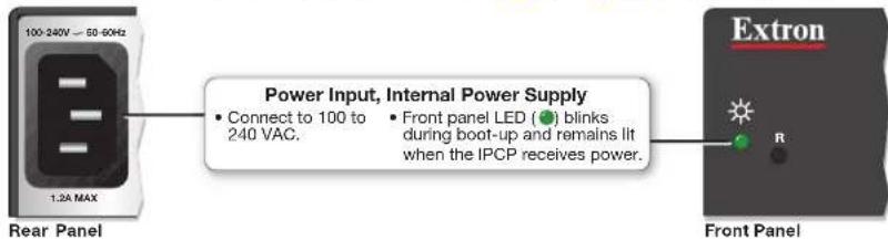
B Power input connector (internal power supply) — Connect the IPCP to a 100 to 240 VAC power source here (see B in Figure 7 on page 12).
flowchart
graph LR
    A["100-240V — 50-60Hz"] --> B["Rear Panel"]
    B --> C["Power Input, Internal Power Supply"]
    C --> D["• Connect to 100 to 240 VAC."]
    C --> E["• Front panel LED (●) blinks during boot-up and remains lit when the IPCP receives power."]
    F["Extron"] --> G["Front Panel"]
    G --> H["R"]
Figure 9. Connecting an Internal Power Supply
Switched 12 VDC power output ports — These ports (see in Figure 7 on page 12) provide 12 VDC output. For the IPCP Pro 550, the four ports provide up to a combined maximum of 40 watts. Once configured, each port can be separately turned on or off. These ports are monitored continuously for total power usage (draw).

Figure 10. Switched Power Output Ports and LEDs
- When the total power usage exceeds a threshold of 41 watts but is still below 47 watts, the IPCP enters the limit mode, during which the yellow front panel Limit LED lights. If you have configured the unit to do so, the IPCP can issue a power overcurrent notice.
- If power usage exceeds a second, higher threshold (47 watts), the IPCP enters overcurrent mode. It turns these ports off, and the red front panel Over LED lights. If the ports are disabled, the user must disconnect or fix the attached devices to correct the problem. If the power draw is still excessive, the ports remain off.
Bidirectional Control and Communication Connections and Features
D 3-pole COM ports, RS-232 only (see D in Figure 7 on page 12) and
E 5-pole COM ports, RS-232/RS-422/RS-485 (see E in Figure 7 on page 12) — Use COM ports for serial control of a display or other device and to receive status messages from the connected devices. These ports can send commands from a driver file. RS-232 is the only mode for the 3-pole ports and is the default mode for the 5-pole ports.
IPCP Pro Series serial protocol:
• 300 to 115200 baud (9600 baud = default)
• 8 (default) or 7 data bits
• 1 (default) or 2 stop bits
- No parity (default), even, odd, mark, or space parity
- Flow control support (default = none):
• 3-pole ports: software-only (XON, XOFF)
- 5-pole ports: hardware and software
Use the following diagram as a wiring guide to cable the IPCP to other devices.

TIP: STP 20-2P cable, shown at left, is recommended for these connections. For best results, insulate the common or drain wires using heat shrink.

flowchart
graph TD
    A["5-pole COM Port"] --> B["Serial (COM) Ports"]
    B --> C["Front Panels"]
    subgraph_A["5-pole COM Pin Configurations"]
        D["Pin: RS-232, RS-422, RS-485"] --> E["1 (Tx)"]
        D --> F["2 (Rx)"]
        D --> G["3 (G)"]
        D --> H["4 (RTS)"]
        D --> I["5 (CTS)"]
    end

    subgraph_B["Serial (COM) Ports"]
        J["3-pole COM (RS-232) xRx G"] --> K["Select protocol via software, COM port default protocol: 9600 baud, 8 data bits, 1 stop bit, no parity, no flow control"]
        L["5-pole COM (RS-232, RS-422, RS-485)"] --> M["NOTE: The 5-pole COM ports support both hardware and software flow control. The 3-pole COM ports support software flow control only."]
    end

    subgraph_A["Serial (COM) Ports"]
        N["RTS = Request to Send, CTS = Clear to Send, Tx = Transmitting Data, Rx = Receiving Data"]
    end

    subgraph_B["Serial (COM) Ports"]
        O["RTS = Request to Send, CTS = Clear to Send, Tx = Transmitting Data, Rx = Receiving Data"]
    end

    subgraph_A["Serial (COM) Ports"]
        P["RTS = Request to Send, CTS = Clear to Send, Tx = Transmitting Data, Rx = Receiving Data"]
    end

    subgraph_B["Serial (COM) Ports"]
        Q["RTS = Request to Send, CTS = Clear to Send, Tx = Transmitting Data, Rx = Receiving Data"]
    end

    subgraph_A["Serial (COM) Ports"]
        R["RTS = Request to Send, CTS = Clear to Send, Tx = Transmitting Data, Rx = Receiving Data"]
    end

    subgraph_B["Serial (COM) Ports"]
        S["RTS = Request to Send, CTS = Clear to Send, Tx = Transmitting Data, Rx = Receiving Data"]
    end

    subgraph_A["Serial (COM) Ports"]
        T["RTS = Request to Send, CTS = Clear to Send, Tx = Transmitting Data, Rx = Receiving Data"]
    end

    subgraph_B["Serial (COM) Ports"]
        U["RTS = Request to Send, CTS = Clear to Send, Tx = Transmitting Data, Rx = Receiving Data"]
    end

    subgraph_A["Serial (COM) Ports"]
        V["RTS = Request to Send, CTS = Clear to Send, Tx = Transmitting Data, Rx = Receiving Data"]
    end

    subgraph_B["Serial (COM) Ports"]
        W["RTS = Request to Send, CTS = Clear to Send, Tx = Transmitting Data, Rx = Receiving Data"]
    end

    subgraph_A["Serial (COM) Ports"]
        X["RTS = Request to Send, CTS = Clear to Send, Tx = Transmitting Data, Rx = Receiving Data"]
    end

    subgraph_B["Serial (COM) Ports"]
        Y["RTS = Request to Send, CTS = Clear to Send, Tx = Transmitting Data, Rx = Receiving Data"]
    end

    subgraph_A["Serial (COM) Ports"]
        Z["RTS = Request to Send, CTS = Clear to Send, Tx = Transmitting Data, Rx = Receiving Data"]
    end

    subgraph_B["Serial (COM) Ports"]
        AA["RTS = Request to Send, CTS = Clear to Send, Tx = Transmitting Data, Rx = Receiving Data"]
    end

    subgraph_A["Serial (COM) Ports"]
        AB["RTS = Request to Send, CTS = Clear to Send, Tx = Transmitting Data, Rx = Receiving Data"]
    end

    subgraph_B["Serial (COM) Ports"]
        AC["RTS = Request to Send, CTS = Clear to Send, Tx = Transmitting Data, Rx = Receiving Data"]
    end

    subgraph_A["Serial (COM) Ports"]
        AD["RTS = Request to Send, CTS = Clear to Send, Tx = Transmitting Data, Rx = Receiving Data"]
    end

    subgraph_B["Serial (COM) Ports"]
        AE["RTS = Request to Send, CTS = Clear to Send, Tx = Transmitting Data, Rx = Receiving Data"]
    end

    subgraph_A["Serial (COM) Ports"]
        AF["RTS = Request to Send, CTS = Clear to Send, Tx = Transmitting Data, Rx = Receiving Data"]
    end

    subgraph_B["Serial (COM) Ports"]
        AG["RTS = Request to Send, CTS = Clear to Send, Tx = Transmitting Data, Rx = Receiving Data"]
    end

    subgraph_A["Serial (COM) Ports"]
        AH["RTS = Request to Send, CTS = Clear to Send, Tx = Transmitting Data, Rx = Receiving Data"]
    end

    subgraph_B["Serial (COM) Ports"]
        AI["RTS = Request to Send, CTS = Clear to Send, Tx = Transmitting Data, Rx = Receiving Data"]
    end

    subgraph_A["Serial (COM) Ports"]
        AJ["RTS = Request to Send, CTS = Clear to Send, Tx = Transmitting Data, Rx = Receiving Data"]
    end

    subgraph_B["Serial (COM) Ports"]
        AK["RTS = Request to Send, CTS = Clear to Send, Tx = Transmitting Data, Rx = Receiving Data"]
    end

    subgraph_A["Serial (COM) Ports"]
        AL["RTS = Request to Send, CTS = Clear to Send, Tx = Transmitting Data, Rx = Receiving Data"]
    end

    subgraph_B["Serial (COM) Ports"]
        AM["RTS = Request to Send, CTS = Clear to Send, Tx = Transmitting Data, Rx = Receiving Data"]
    end

    subgraph_A["Serial (COM) Ports"]
        AN["RTS = Request to Send, CTS = Clear to Send, Tx = Transmitting Data, Rx = Receiving Data"]
    end

    subgraph_B["Serial (COM) Ports"]
        AO["RTS = Request to Send, CTS = Clear to Send, Tx = Transmitting Data, Rx = Receiving Data"]
    end

    subgraph_A["Serial (COM) Ports"]
        AP["RTS = Request to Send, CTS = Clear to Send, Tx = Transmitting Data, Rx = Receiving Data"]
    end

    subgraph_B["Serial (COM) Ports"]
        AQ["RTS = Request to Send, CTS = Clear to Send, Tx = Transmitting Data, Rx = Receiving Data"]
    end

    subgraph_A["Serial (COM) Ports"]
        AR["RTS = Request to Send, CTS = Clear to Send, Tx = Transmitting Data, Rx = Receiving Data"]
    end

    subgraph_B["Serial (COM) Ports"]
        AS["RTS = Request to Send, CTS = Clear to Send, Tx = Transmitting Data, Rx = Receiving Data"]
    end

    subgraph_A["Serial (COM) Ports"]
        AT["RTS = Request to Send, CTS = Clear to Send, Tx = Transmitting Data, Rx = Receiving Data"]
    end

    subgraph_B["Serial (COM) Ports"]
        AU["RTS = Request to Send, CTS = Clear to Send, Tx = Transmitting Data, Rx = Receiving Data"]
    end

    subgraph_A["Serial (COM) Ports"]
        AV["RTS = Request to Send, CTS = Clear to Send, Tx = Transmitting Data, Rx = Receiving Data"]
    end

    subgraph_B["Serial (COM) Ports"]
        AW["RTS = Request to Send, CTS = Clear to Send, Tx = Transmitting Data, Rx = Receiving Data"]
    end

    subgraph_A["Serial (COM) Ports"]
        AX["RTS = Request to Send, CTS = Clear to Send, Tx = Transmitting Data, Rx = Receiving Data"]
    end

    subgraph_B["Serial (COM) Ports"]
        AY["RTS = Request to Send, CTS = Clear to Send, Tx = Transmitting Data, Rx = Receiving Data"]
    end

    subgraph_A["Serial (COM) Ports"]
        AZ["RTS = Request to Send, CTS = Clear to Send, Tx = Transmitting Data, Rx = Receiving Data"]
    end

    subgraph_B["Serial (COM) Ports"]
        BA["RTS = Request to Send, CTS = Clear to Send, Tx = Transmitting Data, Rx = Receiving Data"]
    end

    subgraph_A["Serial (COM) Ports"]
        BB["RTS = Request to Send, CTS = Clear to Send, Tx = Transmitting Data, Rx = Receiving Data"]
    end

    subgraph_B["Serial (COM) Ports"]
        BC["RTS = Request to Send, CTS = Clear to Send, Tx = Transmitting Data, Rx = Receiving Data"]
    end

    subgraph_A["Serial (COM) Ports"]
        BD["RTS = Request to Send, CTS = Clear to Send, Tx = Transmitting Data, Rx = Receiving Data"]
    end

    subgraph_B["Serial (COM) Ports"]
        BE["RTS = Request to Send, CTS = Clear to Send, Tx = Transmitting Data, Rx = Receiving Data"]
    end

    subgraph_A["Serial (COM) Ports"]
        BF["RTS = Request to Send, CTS = Clear to Send, Tx = Transmitting Data, Rx = Receiving Data"]
    end

    subgraph_B["Serial (COM) Ports"]
        BG["RTS = Request to Send, CTS = Clear to Send, Tx = Transmitting Data, Rx = Receiving Data"]
    end

    subgraph_A["Serial (COM) Ports"]
        BH["RTS = Request to Send, CTS = Clear to Send, Tx = Transmitting Data, Rx = Receiving Data"]
    end

    subgraph_B["Serial (COM) Ports"]
        BI["RTS = Request to Send, CTS = Clear to Send, Tx = Transmitting Data, Rx = Receiving Data"]
    end
Figure 11. Wiring COM ports for Serial Control
| 5-pole COM Pin Configurations | |||
| Pin | RS-232 | RS-422 | RS-485 |
| 1 (Tx) | Tx | Tx- | Data-(pins 1 & 2 tied together) |
| 2 (Rx) | Rx | Rx- | |
| 3 (G) | Ground | Ground | Ground |
| 4 (RTS) | RTS | Tx+ | Data+(pins 4 & 5 tied together) |
| 5 (CTS) | CTS | Rx+ | |
For bidirectional serial communication, the transmit, ground, and receive pins must be wired at both the IPCP Pro Series and the other device. Each projector or other device may require different wiring. For details, see the manual for that equipment or read the Extron device driver communication sheet, which is included with the drivers.
NOTE: Maximum distances between the IPCP and the device being controlled are generally up to 200 feet (61 m) but may vary based on factors such as cable gauge, baud rates, environment, and output levels (from the IPCP and the device being controlled).
LAN (IP) connectors and LEDs — To connect the IPCP to an Ethernet network (so you can configure and control the IPCP and the devices connected to it), plug a cable into one of these LAN RJ-45 sockets (see in Figure 7 on page 12) and connect the other end of the cable to a network switch, hub, router, or PC connected to a LAN or the Internet. If the IPCP has more than one LAN port, the rest of the LAN ports function as simple network switches (a multiport, unmanaged switch), so that you can connect additional devices to the same network. For details of communication protocols, ports, and services used, see the Pro Series Control Product Network Ports and Licenses Guide at www.extron.com.
Cabling:
- For 10Base-T (10 Mbps) networks, use a CAT 3 or better cable.
• For 100Base-T (max. 155 Mbps) or 1000Base-T networks, use a CAT 5 or better cable.
You must configure these ports before using them. Configure the settings via Toolbelt or Global Configurator. See the help files for Global Configurator or for Toolbelt for basic information on configuration.
Activity LED (connector and front panel) — This yellow LED blinks to indicate network activity.
Link LED (connector and front panel) — This green LED lights to indicate a good network connection.
1000 LED (front panel) — This green LED lights when the unit is connected to a gigabit network connection.

flowchart
graph TD
    PC -->|Ethernet| TCP/IP_Networks["TCP/IP Network"]
    TCP/IP_Networks -->|Ethernet| Touchlink_Pro_Touchpanel["Touchlink Pro Touchpanel"]
    Touchlink_Pro_Touchpanel --> PC
    Touchlink_Pro_Touchpanel --> TCP/IP_Networks
    PC --> Insert_Twisted_Pair_Wires["Insert Twisted Pair Wires"]
    Insert_Twisted_Pair_Wires --> RJ-45_Connector["RJ-45 Connector"]
    RJ-45_Connector --> Pins["Pins: 12345678"]
    Pins --> Rear_Panel["Rear Panel"]
    Rear_Panel --> LAN1["LAN 1"]
    Rear_Panel --> LAN2["LAN 2"]
    LAN1 -->|or Activity LED| LAN3["LAN"]
    LAN2 -->|or Activity LED| LAN4["LAN"]
    LAN3 --> LinkLED["Link LED"]
    LAN4 --> LinkLED
    Touchlink_Pro_Touchpanel --> Extron_Devices["Extron Devices (Switchers, Scalers)"]
    Extron_Devices --> TCP/IP_Networks
    TCP/IP_Networks --> WaitlinkPro_Touchpanel
    WaitlinkPro_Touchpanel --> WaitlinkPro_Touchpanel
    WaitlinkPro_Touchpanel --> WaitlinkPro_Touchpanel
    WaitlinkPro_Touchpanel --> WaitlinkPro_Touchpanel
    WaitlinkPro_Touchpanel --> WaitlinkPro_Touchpanel
    WaitlinkPro_Touchpanel --> WaitlinkPro_Touchpanel
    WaitlinkPro_Touchpanel --> WaitlinkPro_Touchpanel
    WaitlinkPro_Touchpanel --> WaitlinkPro_Touchpanel
    Delayed_Lower["Default protocol, public ports:<br>• IPCP IP address: 192.168.254.250<br>• Gateway IP address: 0.0.0.0<br>• Subnet mask: 255.255.255.0<br>• DNS address: 127.0.0.1<br>• DHCP: off<br>• Link speed and duplex level: autodetected<br>• Data rates: 10/100/1000Base-T"]
    Delayed_Lower["Default login credentials:<br>• Username: admin<br>• Password: extron"]
    Delayed_Lower --> WaitlineTower["Front Panel"]
    WaitlineTower --> WaitlineTower_1["LAN 1"]
    WaitlineTower_2["LAN 2"]
    WaitlineTower_3["LAN 3"]
    WaitlineTower_4["LAN 4"]
    WaitlineTower_5["LAN 5"]
    WaitlineTower_6["LAN 6"]
    WaitlineTower_7["LAN 7"]
    WaitlineTower_8["LAN 8"]
    WaitlineTower_9["LAN 9"]
    WaitlineTower_10["LAN 10"]
    WaitlineTower_11["LAN 11"]
    WaitlineTower_12["LAN 12"]
    WaitlineTower_13["LAN 13"]
    WaitlineTower_14["LAN 14"]
    WaitlineTower_15["LAN 15"]
    WaitlineTower_16["LAN 16"]
    WaitlineTower_17["LAN 17"]
    WaitlineTower_18["LAN 18"]
    WaitlineTower_19["LAN 19"]
    WaitlineTower_20["LAN 20"]
    WaitlineTower_21["LAN 21"]
    WaitlineTower_22["LAN 22"]
    WaitlineTower_23["LAN 23"]
    WaitlineTower_24["LAN 24"]
    WaitlineTower_25["LAN 25"]
    WaitlineTower_26["LAN 26"]
    WaitlineTower_27["LAN 27"]
    WaitlineTower_28["LAN 28"]
    WaitlineTower_29["LAN 29"]
    WaitlineTower_30["LAN 30"]
    WaitlineTower_31["LAN 31"]
    WaitlineTower_32["LAN 32"]
    WaitlineTower_33["LAN 33"]
    WaitlineTower_34["LAN 34"]
    WaitlineTower_35["LAN 35"]
    WaitlineTower_36["LAN 36"]
    WaitlineTower_37["LAN 37"]
    WaitlineTower_38["LAN 38"]
    WaitlineTower_39["LAN 39"]
    WaitlineTower_40["LAN 40"]
    WaitlineTower_41["LAN 41"]
    WaitlineTower_42["LAN 42"]
    WaitlineTower_43["LAN 43"]
    WaitlineTower_44["LAN 44"]
    WaitlineTower_45["LAN 45"]
    WaitlineTower_46["LAN 46"]
    WaitlineTower_47["LAN 47"]
    WaitlineTower_48["LAN 48"]
    WaitlineTower_49["LAN 49"]
    WaitlineTower_50["LAN 50"]
Figure 12. LAN Connector and LEDs
MAC address (see M in Figure 7 on page 12) — This is the unique user hardware ID number (MAC address) of the unit (for example, 00-05-A6-05-1C-A0). You may need this address during configuration.

Unidirectional Control and Communication Connections
F IR/Serial output ports (see F in Figure 7 on page 12) — An IPCP Pro Series control processor can use infrared signals or unidirectional RS-232 serial signals to control various devices (up to four per port for IR) via these ports. Set output signal type (IR or serial) during configuration. The figure below shows wiring examples.

flowchart
graph TD
    A["Rear Panels"] --> B["IR/Serial Port"]
    B --> C["Output options: IR (30 kHz to 300 kHz, with or without carrier signals) Unidirectional RS-232"]
    B --> D["IR/Serial LEDs"]
    D --> E["Front Panels"]
    E --> F["IR/Serial Port"]
    F --> G["Output signals: IR (30 kHz to 300 kHz, with or without carrier signals) Unidirectional RS-232"]
    F --> H["IR/Serial LEDs"]
    H --> I["Two Single IR Emitters"]
    I --> J["Output signals: IR (30 kHz to 300 kHz, with or without carrier signals) Unidirectional RS-232"]
    I --> K["IR/Serial LEDs"]
    K --> L["Output signals: IR (30 kHz to 300 kHz, with or without carrier signals) Unidirectional RS-232"]
    style A fill:#f9f,stroke:#333
    style B fill:#ccf,stroke:#333
    style F fill:#cfc,stroke:#333
    style H fill:#fcc,stroke:#333
    style I fill:#cff,stroke:#333
    style K fill:#ffc,stroke:#333
Figure 13. Wiring the IR/Serial Ports
Serial control: Connect one of these ports to the serial control receive (Rx) and ground pins of the device to be controlled. These ports have the same serial protocol options (see page 15) as the COM ports.
IR control: Connect one of these ports directly to the wired IR port of another device. Or insert the wires from up to four IR Emitters into an IR port and place the heads of the emitters over or next to the IR signal pickup windows of the devices. For wiring, see the following diagrams or the IR Emitter Installation Guide (available on www.extron.com).
NOTE: Each emitter must be within 100 feet of the IPCP for best IR control results.
Installing One Single Emitter
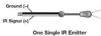
Installing One Dual Emitter

Installing Two Single Emitters
When installing only single emitters, tie them in series as shown below.

Two Single IR Emitters
G Relay ports — Relay ports (see G in Figure 7 on page 12) provide control for power, for screen or projector lifts, window coverings, and similar items, when trigger events occur.

flowchart
graph TD
    A["All relays are normally open."] --> B["Relays"]
    B --> C["Relays 1: Common Open (1)"]
    B --> D["Relays 2: Common Open (2)"]
    B --> E["Relays 3: Common Open (3)"]
    B --> F["Relays 4: Common Open (4)"]
    B --> G["Relays 5: Common Open (5)"]
    B --> H["Relays 6: Common Open (6)"]
    B --> I["Relays 7: Common Open (7)"]
    B --> J["Relays 8: Common Open (8)"]
    B --> K["Relays 9: Common Open (9)"]
    B --> L["Relays 10: Common Open (10)"]
    B --> M["Relays 11: Common Open (11)"]
    B --> N["Relays 12: Common Open (12)"]
    B --> O["Relays 13: Common Open (13)"]
    B --> P["Relays 14: Common Open (14)"]
    B --> Q["Relays 15: Common Open (15)"]
    B --> R["Relays 16: Common Open (16)"]
    B --> S["Relays 17: Common Open (17)"]
    B --> T["Relays 18: Common Open (18)"]
    B --> U["Relays 19: Common Open (19)"]
    B --> V["Relays 20: Common Open (20)"]
    B --> W["Relays 21: Common Open (21)"]
    B --> X["Relays 22: Common Open (22)"]
    B --> Y["Relays 23: Common Open (23)"]
    B --> Z["Relays 24: Common Open (24)"]
    B --> AA["Relays 25: Common Open (25)"]
    B --> AB["Relays 26: Common Open (26)"]
    B --> AC["Relays 27: Common Open (27)"]
    B --> AD["Relays 28: Common Open (28)"]
    B --> AE["Relays 29: Common Open (29)"]
    B --> AF["Relays 30: Common Open (30)"]
    B --> AG["Relays 31: Common Open (31)"]
    B --> AH["Relays 32: Common Open (32)"]
    B --> AI["Relays 33: Common Open (33)"]
    B --> AJ["Relays 34: Common Open (34)"]
    B --> AK["Relays 35: Common Open (35)"]
    B --> AL["Relays 36: Common Open (36)"]
    B --> AM["Relays 37: Common Open (37)"]
    B --> AN["Relays 38: Common Open (38)"]
    B --> AO["Relays 39: Common Open (39)"]
    B --> AP["Relays 40: Common Open (40)"]
    B --> AQ["Relays 41: Common Open (41)"]
    B --> AR["Relays 42: Common Open (42)"]
    B --> AS["Relays 43: Common Open (43)"]
    B --> AT["Relays 44: Common Open (44)"]
    B --> AU["Relays 45: Common Open (45)"]
    B --> AV["Relays 46: Common Open (46)"]
    B --> AW["Relays 47: Common Open (47)"]
    B --> AX["Relays 48: Common Open (48)"]
    B --> AY["Relays 49: Common Open (49)"]
    B --> AZ["Relays 50: Common Open (50)"]
    B --> BA["Relays 51: Common Open (51)"]
    B --> BB["Relays 52: Common Open (52)"]
    B --> BC["Relays 53: Common Open (53)"]
    B --> BD["Relays 54: Common Open (54)"]
    B --> BE["Relays 55: Common Open (55)"]
    B --> BF["Relays 56: Common Open (56)"]
    B --> BG["Relays 57: Common Open (57)"]
    B --> BH["Relays 58: Common Open (58)"]
    B --> BI["Relays 59: Common Open (59)"]
    B --> BJ["Relays 60: Common Open (60)"]
    B --> BK["Relays 61: Common Open (61)"]
    B --> BL["Relays 62: Common Open (62)"]
    B --> BM["Relays 63: Common Open (63)"]
    B --> BN["Relays 64: Common Open (64)"]
    B --> BO["Relays 65: Common Open (65)"]
    B --> BP["Relays 66: Common Open (66)"]
    B --> BQ["Relays 67: Common Open (67)"]
    B --> BR["Relays 68: Common Open (68)"]
    B --> BS["Relays 69: Common Open (69)"]
    B --> BT["Relays 70: Common Open (70)"]
    B --> BU["Relays 71: Common Open (71)"]
    B --> BV["Relays 72: Common Open (72)"]
    B --> BW["Relays 73: Common Open (73)"]
    B --> BX["Relays 74: Common Open (74)"]
    B --> BY["Relays 75: Common Open (75)"]
    B --> BZ["Relays 76: Common Open (76)"]
    B --> CA["Relays 77: Common Open (77)"]
    B --> CB["Relays 78: Common Open (78)"]
    B --> CC["Relays 79: Common Open (79)"]
    B --> CD["Relays 80: Common Open (80)"]
Figure 14. Cabling Relay Ports
These relay contacts may be used to control any equipment as long as the contact specifications of a total of 24 volts at 1 ampere are not exceeded for each port. These relays are normally open by default.
When activated, the open contacts close. They can be set up to operate in one of two ways:
• Latching (brief or indefinite period contact) (press to close, press to open), or
- Pulsed (timed cycle) (press to close, timeout to open, with automatic repeat).
In pulse mode the default timeout period (hold time) is 12 second (500 ms). Use Global Configurator to change the length of the timeout period.
NOTE: The pulse function is absolute: it always sets the relay state to closed, times out (briefly), then opens the contact. It overrides the previously selected setting (on state, off state, or toggle).
Additional Control Ports
Flex I/O ports (see H in Figure 7 on page 12) —To allow the IPCP Pro Series control processor to monitor devices to trigger events, connect switches, sensors, LEDs, relays, or similar items to these ports, which can be configured as analog inputs, or as digital inputs or outputs with or without +5 VDC pull-up. These ports can trigger events or functions (such as triggering relays, issuing commands, or sending an e-mail) that have been configured using GC. By default these ports are set to digital input mode with pullup disabled.

Figure 15. Flex I/O Port Wiring Examples
Analog input — When a Flex I/O port is configured as an analog input, the port can measure 0 to 25.3 VDC with 12-bit accuracy. A DC level is indicated by a count from 0-4096 ( ≈ 6 mV per count).
Digital input — To allow the IPCP to monitor external devices that do not use RS-232 communication, connect a switch, motion sensor, moisture sensor, tally feedback output, button pad, or a similar item to a Flex I/O port and configure it for digital input. When configured as a digital input, the port is set to measure two states: high and low. The port accepts 0 to 25.3 VDC input.
For flex I/O ports, threshold voltages are adjustable. Default thresholds are:
• 0.8 VDC — port on, logic low
• 2.4 VDC — port off, logic high
There is also an internal, selectable, pull-up resistor connected to +5 VDC.
Digital output — To power LEDs, incandescent lights, or other devices that accept a TTL signal, or to provide contact closure control for projector lifts, motorized screens, room or light switches via an Extron IPA T RLY4 or similar device, you can use one or more of these ports as a digital output. When a port is configured for digital output, it offers two output states: on and off.
- When the port is set to an "on" state, (the circuit is closed), the I/O pin is connected to ground. Output voltage is less than 0.5 volts.
- When the port is set to the "off" state (the circuit is open), the output pin is not connected. If the application calls for TTL compatibility, the digital output circuit can be set up to provide a 2k ohm pull-up resistor to +5 VDC.
- If the pull-up resistor is disabled, voltage output is determined by an external source device.
• If the pull-up resistor is enabled, voltage output is 4.3 VDC.
Each I/O port is capable of accepting 250 mA, maximum.
Digital I/O (digital input/output) ports — These ports work the same way the flex I/O ports work, but they do not offer analog input, and thresholds are not adjustable. Connect switches, sensors, LEDs, relays, or similar items to these ports (see 1 in
Figure 7 on page 12), which can be configured as digital inputs or outputs, with or without +5 VDC pull-up. These ports can trigger events or functions (such as triggering relays, issuing commands, or sending an e-mail) that have been configured using Global Configurator.

flowchart
graph TD
    A["Digital I/O"] --> B["Rear Panel"]
    B --> C["Switch, Sensor"]
    C --> D["Device 1"]
    C --> E["Device 2"]
    C --> F["Device 3"]
    C --> G["Device 4"]
    C --> H["Device 5"]
    C --> I["Device 6"]
    C --> J["Device 7"]
    C --> K["Device 8"]
    C --> L["Device 9"]
    C --> M["Device 10"]
    C --> N["Device 11"]
    C --> O["Device 12"]
    C --> P["Device 13"]
    C --> Q["Device 14"]
    C --> R["Device 15"]
    C --> S["Device 16"]
    C --> T["Device 17"]
    C --> U["Device 18"]
    C --> V["Device 19"]
    C --> W["Device 20"]
    C --> X["Device 21"]
    C --> Y["Device 22"]
    C --> Z["Device 23"]
    C --> AA["Device 24"]
    C --> AB["Device 25"]
    C --> AC["Device 26"]
    C --> AD["Device 27"]
    C --> AE["Device 28"]
    C --> AF["Device 29"]
    C --> AG["Device 30"]
    C --> AH["Device 31"]
    C --> AI["Device 32"]
    C --> AJ["Device 33"]
    C --> AK["Device 34"]
    C --> AL["Device 35"]
    C --> AM["Device 36"]
    C --> AN["Device 37"]
    C --> AO["Device 38"]
    C --> AP["Device 39"]
    C --> AQ["Device 40"]
    C --> AR["Device 41"]
    C --> AS["Device 42"]
    C --> AT["Device 43"]
    C --> AU["Device 44"]
    C --> AV["Device 45"]
    C --> AW["Device 46"]
    C --> AX["Device 47"]
    C --> AY["Device 48"]
    C --> AZ["Device 49"]
    C --> BA["Device 50"]
    C --> BB["Device 51"]
    C --> BC["Device 52"]
    C --> BD["Device 53"]
    C --> BE["Device 54"]
    C --> BF["Device 55"]
    C --> BG["Device 56"]
    C --> BH["Device 57"]
    C --> BI["Device 58"]
    C --> BJ["Device 59"]
    C --> BK["Device 60"]
    C --> BL["Device 61"]
    C --> BM["Device 62"]
    C --> BN["Device 63"]
    C --> BO["Device 64"]
    C --> BP["Device 65"]
    C --> BQ["Device 66"]
    C --> BR["Device 67"]
    C --> BS["Device 68"]
    C --> BT["Device 69"]
    C --> BU["Device 70"]
    C --> BV["Device 71"]
    C --> BW["Device 72"]
    C --> BX["Device 73"]
    C --> BY["Device 74"]
    C --> BZ["Device 75"]
    C --> CA["Device 76"]
    C --> CB["Device 77"]
    C --> CC["Device 78"]
    C --> CD["Device 79"]
    C --> CE["Device 80"]
Figure 16. Digital I/O Port Wiring Examples
Digital input — To allow the IPCP to monitor external devices that do not use RS-232 communication, connect a switch, motion sensor, moisture sensor, tally feedback output, button pad, or a similar item to a digital I/O port and configure it for digital input. When configured as a digital input, the port is set to measure two states: high and low. The port accepts 0 to 25.3 VDC input.
Unlike flex I/O ports, for digital I/O ports, threshold voltages are not adjustable. Thresholds are:
• 2.0 VDC — port on, logic low
• 2.8 VDC — port off, logic high
There is also an internal, selectable, pull-up resistor connected to +5 VDC.
Digital output — To power LEDs, incandescent lights, or other devices that accept a TTL signal, or to provide contact closure control for projector lifts, motorized screens, room or light switches via an Extron IPA T RLY4 or similar device, you can use one or more of these ports as a digital output. When a port is configured for digital output, it offers two output states: on and off.
- When the port is set to an "on" state, (the circuit is closed), the I/O pin is connected to ground. Output voltage is less than 0.5 volts.
-
When the port is set to the "off" state (the circuit is open), the output pin is not connected. If the application calls for TTL compatibility, the digital output circuit can be set up to provide a 2k ohm pull-up resistor to +5 VDC.
-
If the pull-up resistor is disabled, voltage output is determined by an external source device.
• If the pull-up resistor is enabled, voltage output is 4.3 VDC.
Each I/O port is capable of accepting 250 mA, maximum.
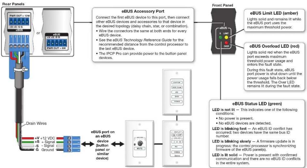
eBUS port (see in Figure 7 on page 12) — eBUS is a technology (proprietary bus architecture and serial communication protocol) developed by Extron. It allows many eBUS devices (such as button panels) and accessories (including power and signal hubs) to be connected to a single control processor to expand the capabilities of a control system. Button panels are automatically recognized by the host control processor and can be added or removed at any time.
See the eBUS Technology Reference Guide (part 68-1499-01) before you install eBUS devices and accessories. It explains how to determine how many devices are supported when directly connected to the control processor and where (at what distances and what points in a system) and when it is advisable to add external power supplies. Also see the guide for each eBUS device for detailed installation information specific to each product, such as how to set the eBUS address and mount the devices. Each device in a system must have a distinct eBUS address that is not shared with any other device in the same system.
Wire both ends the same on each cable that connects eBUS devices. Extron STP 20 Series cable is recommended for these connections (see the cable preparation diagram on page 15).
flowchart
graph TD
    A["Rear Panels"] --> B["Drain Wires"]
    B --> C["+V +12 VDC"]
    B --> D["+S + Signal"]
    B --> E["-S - Signal"]
    B --> F["G Ground"]
    C --> G["eBUS port on an eBUS device (button panel or similar device)"]
    D --> G
    E --> G
    F --> G
    G --> H["eBUS Accessory Port"]
    H --> I["Front Panel"]
    I --> J["eBUS Limit LED (amber)"]
    I --> K["eBUS Overload LED (red)"]
    J --> L["LED is not lit — This indicates one of the following conditions: No power is present. No eBUS devices are detected."]
    K --> M["LED is blinking fast — An eBUS ID conflict has occurred: two devices have the same bus ID number."]
    K --> N["LED is blinking slowly — A firmware update is in progress: the control processor is synchronizing firmware of the eBUS panel(s)."]
    K --> O["LED is lit solid — Power is present with confirmed communication and there are no eBUS ID conflicts in the entire system."]
Figure 17. eBUS Port Cabling and Front Panel LED Indication
This port provides power to eBUS devices. If the power draw by the connected devices reaches the maximum level allowed, the eBUS Limit LED lights. If the power consumption exceeds the allowed threshold, the IPCP shuts off the eBUS port and lights the eBUS Overload (Over) LED. If that occurs, you must resolve the hardware cause of the power overload before the IPCP can successfully restore function to this port. Once the power consumption of the port is reduced to below the maximum overload condition threshold, the eBUS port automatically re-enables and resumes function.
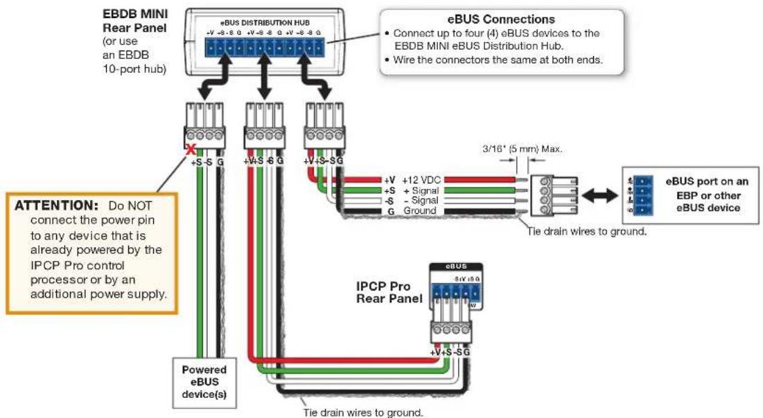
If additional power supplies are required for an eBUS system, consider the following:
- Do not connect power from both the IPCP and the supplemental power supply to any eBUS device.
- Do not allow power from the supplemental power supply to flow to the IPCP.
See the following diagram as an example of a system where both an IPCP and a supplemental power supply are included in the eBUS topology.
flowchart
graph TD
    A["EBDB MINI Rear Panel (or use an EBDB 10-port hub)"] --> B["eBUS Distribution Hub"]
    B --> C["Connect up to four (4) eBUS devices to the EBDB MINI eBUS Distribution Hub."]
    B --> D["Wire the connectors the same at both ends."]
    B --> E["+V +S -G"]
    B --> F["+V +S -G"]
    B --> G["+V +S -G"]
    B --> H["+V +S -G"]
    B --> I["+V +S -G"]
    B --> J["+V +S -G"]
    B --> K["+V +S -G"]
    B --> L["+V +S -G"]
    B --> M["+V +S -G"]
    B --> N["+V +S -G"]
    B --> O["+V +S -G"]
    B --> P["+V +S -G"]
    B --> Q["+V +S -G"]
    B --> R["+V +S -G"]
    B --> S["+V +S -G"]
    B --> T["+V +S -G"]
    B --> U["+V +S -G"]
    B --> V["+V +S -G"]
    B --> W["+V +S -G"]
    B --> X["+V +S -G"]
    B --> Y["+V +S -G"]
    B --> Z["+V +S -G"]
    B --> AA["+V +S -G"]
    B --> AB["+V +S -G"]
    B --> AC["+V +S -G"]
    B --> AD["+V +S -G"]
    B --> AE["+V +S -G"]
    B --> AF["+V +S -G"]
    B --> AG["+V +S -G"]
    B --> AH["+V +S -G"]
    B --> AI["+V +S -G"]
    B --> AJ["+V +S -G"]
    B --> AK["+V +S -G"]
    B --> AL["+V +S -G"]
    B --> AM["+V +S -G"]
    B --> AN["+V +S -G"]
    B --> AO["+V +S -G"]
    B --> AP["+V +S -G"]
    B --> AQ["+V +S -G"]
    B --> AR["+V +S -G"]
    B --> AS["+V +S -G"]
    B --> AT["+V +S -G"]
    B --> AU["+V +S -G"]
    B --> AV["+V +S -G"]
    B --> AW["+V +S -G"]
    B --> AX["+V +S -G"]
    B --> AY["+V +S -G"]
    B --> AZ["+V +S -G"]
    B --> BA["+V +S -G"]
    B --> BB["+V +S -G"]
    B --> BC["+V +S -G"]
    B --> BD["+V +S -G"]
    B --> BE["+V +S -G"]
    B --> BF["+V +S -G"]
    B --> BG["+V +S -G"]
    B --> BH["+V +S -G"]
    B --> BI["+V +S -G"]
    B --> BJ["+V +S -G"]
    B --> BK["+V +S -G"]
    B --> BL["+V +S -G"]
    B --> BM["+V +S -G"]
    B --> BN["+V +S -G"]
    B --> BO["+V +S -G"]
    B --> BP["+V +S -G"]
    B --> BPB["+V +S -G"]
    B --> BPBb["+V +S -G"]
    B --> BPBc["+V +S -G"]
    B --> BPBd["+V +S -G"]
    B --> BPBdBi["+V +S -G"]
    B --> BPBdC["+V +S -G"]
    B --> BPBdD["+V +S -G"]
    B --> BPBdE["+V +S -G"]
    B --> BPBdF["+V +S -G"]
    B --> BPBdG["+V +S -G"]
    B --> BPBdH["+V +S -G"]
    B --> BPBdHb["+V +S -G"]
    B --> BPBdHc["+V +S -G"]
    B --> BPBdHd["+V +S -G"]
    B --> BPBdHf["+V +S -G"]
    B --> BPBdHg["+V +S -G"]
    B --> BPBdHh["+V +S -G"]
    B --> BPBdHg
    B --> BPBdHh
Figure 18. Connecting eBUS Devices in a System With Both an IPCP and Another Powered eBUS Device
Volume control port — To provide volume control for Extron half rack audio amplifiers, connect this port (see in Figure 7 on page 12) to the volume remote control port on the amplifier as shown below. Configure the maximum and minimum voltage limits. Set Soft Start mode off or on (default). Soft Start mode allows volume to gradually increase from mute to the previous level after muting or power-on to prevent loud audio bursts.

NOTE: Use shielded cable and place the control processor as close as possible to the amplifier to avoid picking up background noise via the cable. Ideal cable length is six feet or less.

NOTE: When audio mute is active, the control processor sets output voltage to 0 VDC, even if the voltage range (minimum and maximum voltage limits) has been set to levels above zero, such as 2 V to 8 V.
Figure 19. Volume Control Port Wiring Examples
Resetting the Unit
There are four reset modes that are available by pressing the Reset button on the front panel (for most models) or the rear panel (for the IPCP Pro 350M). The Reset button is recessed, so use a pointed stylus, ballpoint pen, or Extron Tweeker to access it. See the reset modes table below and on the next page for a summary of the modes.
ATTENTION:
NOTE: If you hold down the reset button continuously, the LED blinks every 3 seconds, and the unit enters a different mode, from the Reset all IP Settings mode through the Reset to Factory Defaults mode. For Reset to Factory Defaults mode the LED blinks three times, the third blink indicating the last mode. The modes are separate functions, not a continuation from one mode to the next.
| IPCP Pro Series Control Processor Reset Mode Summary | |||
| Mode | Use This Mode to... | Activation Result | |
| Use Factory FirmwareMode | Temporarily boot up the unit with factory-installed firmware for a single power cycle in the event that a firmware update has failed or if incompatibility issues arise with user-loaded firmwareUse This Mode to... | To start the Use Factory Firmware reset mode and replace firmware:1. On the control processor, hold down the recessedResetbutton while applying power to the unit. Hold the button down until thePowerLED flashes twice, then release the button. The control processor enters factory firmware mode, and the LED flashes quickly.2. Upload new firmware to the unit as desired (seeUpdatingtheFirmwareon page 36 for details).NOTE:Do notcontinue to operate the IPCP Pro controlprocessor using the factory firmware version. If you want to use the factory default firmware version, you must upload that version again. See theGlobal Configurator Helpfile for firmware upload instructions.Activation Result | The control processor reverts to thefactory default firmware. Event scripting does not start if the unit is powered on in this mode. All user files and settings such as drivers, adjustments, and IP settings are maintained.NOTE:To return the unit to the firmware version that was running prior to the reset, cycle power to the unit. |
| Project Recovery | Recover project configuration and program files if passwords have been lost | For devices with firmware version 1.04 and lower | |
| To start the Project Recovery reset mode and recover a project:1. On the PC, open Global Configurator.2. Click theToolsmenu and selectProject Recovery.The Recovery Modedialog box opens.3. Enter the IP address or host name of the target device for which you want to perform project recovery.4. ClickRecover.The software allows indefinite time to establish a connection (until a connection is made or the user clicksCancel).5. On the control processor, hold down theResetbutton while applying power to the unit. Hold the button down until thePower LED blinks twice, then release the button. The control processor enters project recovery mode for 20 seconds, during which time thePower LED blinks quickly. GC automatically connects to the control processor, then opens and retrieves the project from the unit.6. Cycle power to the control processor to exit project recovery mode.7. Perform theReset to Factory Defaultsreset on the control processor.8. Open Toolbelt, start device discovery, select the desired control processor from the list and clickManage.9. Click theNetwork Settingstab and set the IP address of the control processor.10. Click theUser Managementtab and change the password of the control processor.11. Close Toolbelt.12. In GC, add the new password to the recovered project.13. Save the project.14. Upload the project from GC to the control processor. | Project Recovery mode stops regular operation and allows a connection to be made to the unit via GC software without requiring password entry so that project files can be retrieved and saved.During project recovery mode, events are stopped, and so is communication with AV devices.While the control processor is in this mode, use the GC software to recover project files.If the software does not initiate project recovery within 30 seconds after the control processor enters this mode, the control processor exits recovery mode.Upon exiting project recovery mode:The unit returns to its pre-recovery mode state and settings.The Power LED returns to being steadily lit. | ||
| For devices with firmware version 1.05 and higher | |||
| To start the Project Recovery reset mode and recover a project:1. On the PC, open Global Configurator.2. Click theToolsmenu and selectProject Recovery.The Recovery Modedialog box opens.3. Enter the IP address or host name of the target device for which you want to perform project recovery.4. ClickRecover.The software allows indefinite time to establish a connection (until a connection is made or the user clicksCancel).5. On the control processor, press theResetbutton three times within one second. The control processor enters project recovery mode for 30 seconds, during which time thePower LED blinks quickly. GC automatically connects to the control processor, then opens and retrieves the project from the unit.6. Cycle power to the control processor to exit project recovery mode.7. Perform theReset to Factory Defaultsreset on the control processor.8. Open Toolbelt, start device discovery, select the desired control processor from the list and clickManage.9. Click theNetwork Settingstab and set the IP address of the control processor.11. Close Toolbelt.12. In GC, add the new password to the recovered project.13. Save the project.14. Upload the project from GC to the control processor. | Project Recovery mode stops regular operation and allows a connection to be made to the unit via GC software without requiring password entry so that project files can be retrieved and saved.During project recovery mode, events are stopped, and so is communication with AV devices.While the Control processor is in this mode, use the GC software to recover project files.If the software does not initiate project recovery within 30 seconds after the control processor enters this mode, the control processor exits recovery mode.Upon exiting project recovery mode:The unit returns to its pre-recovery mode state and settings.The Power LED returns to being steadily lit. | ||
| IPCP Pro Series Control Processor Reset Mode Summary | |||
| Mode | Use This Mode to... | Activation Result | |
| Run/Stop Program | Toggle stop/start program | To stop or start a program:1. Hold down theResetbutton for about 3 seconds, until the Power LED blinks once.2. Release and press theResetbutton momentarily (for <1 second) within 1 second*.* Nothing happens if the momentary press does not occur within 1 second.NOTE:This reset mode is supported on firmware version 2.00.0002-b004 and higher. | The LED flashes 2 times if the program is starting.The LED flashes 3 times if the program is stopping. |
| Reset All IP Settings | Reset IP settings and port maps to factory defaults without affecting user-loaded files | To reset all IP settings:1. Hold down theResetbutton for about 6 seconds until the Power LED blinks twice (once at 3 seconds, again at 6 seconds).2. Release and press theResetbutton momentarily (for <1 second) within 1 second*.* Nothing happens if the momentary press does not occur within 1 second. | Reset All IP Settings mode:Sets the LAN IP address back to factory default (192.168.254.250)Sets the subnet back to factory default (255.255.255.0)Sets the default gateway address to the factory default (0.0.0.0)Sets domain and host names to factory defaultSets port mapping back to factory defaultTurns DHCP offTurns events (user-created schedules, macros) off. |
| Reset to Factory Defaults | Start over with configuration and uploading | To reset the unit to all factory default settings:1. Hold down theResetbutton for about 9 seconds until the Power LED blinks three times (once at 3 seconds, again at 6 seconds, again at 9 seconds).2. Release and press theResetbutton momentarily (for <1 second) within 1 second*.* Nothing happens if the momentary press does not occur within 1 second. | Reset to Factory Defaults mode performs a complete reset to factory defaults (except the firmware).Does everything Reset All IP Settings mode doesRemoves (clears) all user-loaded files and configurations from the control processor:Clears driver-port associations (IR, serial, Ethernet) and port configurationsRemoves button/touchpanel configurationsRemoves schedules, settings, macros |
NOTE: After performing a Reset All IP Settings or Reset to Factory Defaults reset, set the IP address again (by using Toolbelt) for use on your network.
Software-Based Configuration and Control
This section of the guide is divided into the following topics:
- Configuration and Control: an Overview
- Basic Setup Steps: a Guide to this Section and Other Resources
- Downloading the Software and Getting Started
- Troubleshooting
Configuration and Control: an Overview
An IPCP must be configured before use in order to recognize and accept commands and pass them on to the controlled devices. It can be configured and controlled via a host computer connected to the same network as the control processor. See LAN (IP) connectors and LEDs starting on page 16 for details about LAN port and cabling to connect the control processor to the network.
- Configure the control processor by using the Global Configurator software in GC Professional or GC Plus mode. See the Extron website for full system hardware and software requirements.
- The default web pages embedded within the control processor provide a means to view general hardware information, network settings, and, if configured, project information. The embedded web pages can also be used to update the IPCP firmware. You cannot configure the control processor via the embedded web pages.
Basic Setup Steps: a Guide to this Section and Other Resources
NOTE: GC projects can be created offline and uploaded to the hardware at a later date.
Follow the steps in Setup Checklist: How to Proceed With Installation starting on page 7. The overall process for setting up a control processor is as follows:

flowchart
graph TD
    A["Configure the IP settings of the control processor and the TouchLink Pro touchpanels."] --> B["Create a new GC Professional or GC Plus project and add the control processor to it."]
    C["See "Network Communication Setup" in this guide."] --> B
    B --> D{Will TouchLink Pro or third party touchpanels or other user interfaces be used?}
    D -->|No Yes| E["Configure ports on the control processor."]
    D -->|Yes| F["Create GUI layouts for the touchpanels or other interfaces: 1. Start GUI Designer.<br>2. Create GUI layout designs for each TouchLink Pro or third party touchpanel (with a TouchLink Interface), or for a computer or mobile device (with LinkLicense).<br>3. Save and build the GUI layout file. Or...<br>Download existing GUI layouts from identical touchpanels."]
    E --> G["Create monitors, schedules, timers, macros, and local variables."]
    G --> H["Add touchpanels or other interfaces (if used) to the project."]
    H --> I["Import GUI layouts and configure the touchpanels or other interfaces."]
    I --> J["Save the project."]
    J --> K["Build and upload the configuration to the control processor."]
    K --> L["Test the system, make adjustments, finalize configuration."]
Figure 20. Overall Configuration Steps
Downloading the Software and Getting Started
GC software updates and a large variety of device drivers can be downloaded from the Download page on the Extron website (www.extron.com/download/index.aspx). When you locate the desired software or driver package, follow the on-screen directions to download and install it.
NOTE: New RS-232 and Ethernet drivers are required. You must use serial and Ethernet drivers developed specifically for the IP Link Pro platform. With the exception of IR device drivers, drivers used for the previous generation IP Link (non-Pro) control processors are not compatible.
Locating Software, Firmware, and Driver Files on the Extron Website
There are three main ways to find software, firmware, and device drivers within www.extron.com:
• Via links from the Web page for the specific product
- Via the Download Center page (Click on the Download tab at the top of any page within the Extron website.)
• Via links from search results
NOTE: For some software you have the option to click the Download button to begin downloading the software file. For other software there is a link for contacting an Extron support representative who can provide you access to the latest version. To obtain Global Configurator (GC Professional, GC Plus) software, you must have an Extron Insider account and contact an Extron support representative. Extron provides training to our customers on how to use the software. For Global Configurator Professional, you must first attend Extron training, pass a proficiency test, and achieve Extron Control Professional Certification before being able to download that program.
Via links from the Web page for the specific product
-
Navigate to the Web page for the specific product model by either...
-
Typing the model name into the search field in the upper right of any Extron Web page and clicking the magnifying glass icon or
-
Selecting the model name from the Product Shortcuts drop-down list in the upper left of the Extron home page or Products page.
-
Click the Downloads tab in the middle of the product page. A list of available software, firmware, and documents for that model appears on screen.
- Click on the name of the desired software or firmware to start downloading the file, or click on the link for device drivers to navigate to a page from which you can select either a driver package or specific drivers for individual devices.
Via the Download Center page
- Click on the Download tab at the top of any page within the Extron website to access the Download Center.
-
Click on the link for the desired software product category (such as IP Link Pro software, TouchLink software, or device drivers) in the center of the screen. A page opens that allows you to make more specific selections from within that category.
-
For software, click on the link for the specific software that you need. A software product page opens that provides a description of the software package, a list of system requirements, a list of features, and access to the release notes, in addition to a download link.
For drivers, select a product name from the drop-down list. -
For some software you can click the Download or Download Now button to begin downloading the software file. For other software there is a link for contacting an Extron support representative who can provide you access to the latest version.
For drivers, navigate through the alphabetically arranged list to select and download a driver for a specific device.
Via links from search results
- Type the specific name of the software package (such as Global Configurator or GUI Designer) into the search field in the upper right of the Extron Web page and click the magnifying glass icon. A search results page appears.
- Click on the name of the software package. A software product page opens that provides a description of the software package, a list of system requirements, a list of features, and access to the release notes, in addition to a download link.
- For some software you can click the Download or Download Now button to begin downloading the software file. For other software there may be a link for contacting an Extron support representative who can provide you access to the latest version.
Obtaining Control Drivers
Extron provides an extensive selection of device drivers available on the Extron website. Ethernet, serial, and infrared (IR) device drivers (for controlling projectors, displays, DVD players, document cameras, and so forth) are available as individual device driver files. Prior to configuration, download driver files for products to be used in the installation.
NOTE: For serial or Ethernet devices, IPCP Pro Series control processors require IP Link Pro drivers. They do not support serial or Ethernet drivers that were created for IP Link (non-Pro) products. However, existing Extron IR driver files are supported.
If the system requires a driver that is not already available, you have additional options:
- Request a new serial (RS-232) or Ethernet driver from Extron.
- Create your own custom IR device driver using the IR learning feature within GC or Extron IR Learner software. The IR learning feature makes it possible to capture infrared codes from a handheld IR remote control and create custom drivers for operating the corresponding IR-controlled device. Follow the directions in the help file to create a driver by using the remote control for that device and the IR receiver port on the front panel of the IPCP Pro.
NOTE: The IPCP 350M does not have an IR learning sensor.
Things to Do After Installing GC and Before Starting a Project
- Read the Global Configurator Help file for details and step-by-step procedures on how to start a GC Professional or GC Plus project and perform basic setup tasks for a control processor.
- Obtain network addresses and related information from your network administrator.
- Set up the IP address for the control processor. See Network Communication Setup on page 9 for an overview of how to set up the network properties of the unit. For details, see the GC help file or Toolbelt help file, which contains instructions on how to set the IP address, gateway IP address, subnet mask, mail server IP address, domain name, Web port, SMTP username, and SMTP password so that the IPCP is able to communicate with the network.
Using GC: Helpful Tips
Resources and Notes
- The IPCP Pro Series Setup Guide is shipped with the unit, and it lists available resources (software, drivers, instructions). It includes a quick reference to the front and rear panel features, and covers basic hardware installation.
- The Global Configurator Help file provides a wealth of information on settings and how to use the software, itself. The help file, included with the software, covers basic setup steps and includes examples of how to use the features of GC and step by step instructions for typical configuration tasks.
- See Front Panel Features on page 10 and Rear Panel Features and Connections on page 12 in the "Hardware Features and Installation" section of this guide for features and settings for the ports you are configuring.
- If you will configure the IPCP at the installation site, Extron recommends downloading drivers for all the devices in the installation before you go out into the field.
- The Global Configurator project file (*.gcpro or *.gcplus) contains configuration settings and it can be saved to a directory or folder for backup or for installation on another IPCP Pro control processor. Saving a configuration is recommended before you perform a firmware upgrade.
- The IPCP can be set up to allow configuration access only to administrators to prevent other users from making changes to settings, events, and controls.
- IP address, subnet mask, and gateway address are required during network setup of the control processor.
-
The unit name is any name (for example, Room730-IPCPPPro550 or ConfRmSystem) that you want to use to label a specific IPCP unit. The default is a combination of the product name and part of the hardware (MAC) address. This can be changed to your choice of alphanumeric characters and hyphens (-). The following rules apply:
-
Spaces are not permitted within the name of a unit or at the start or the end of a name.
- Underscores ( _ ) are not permitted.
- Valid characters are A-Z, a-z, 0-9, and - (hyphen).
- The name cannot start with a number or a hyphen, and it cannot end with a hyphen.
• Maximum name length is 128 characters.
Troubleshooting
Turn on the input devices (DVD players, Blu-ray players, PCs, and other sources), output devices (display screens, projectors), the control processor, and the PC and touchpanel or eBUS button panels. Touch a configured button on the touchpanel or eBUS button panel.
If an input or output AV device cannot be remotely controlled (does not respond as expected), check the following:
Power Connections
- Ensure that all devices are plugged in.
- Make sure that each device is receiving power. The IPCP front panel power LED lights if the device is receiving power.
-
If the IPCP includes switched power output ports, verify that the overload indicator LED is not lit. If the switched 12 VDC power output Over LED is lit, the power draw at the switched power ports has been exceeded. To restore these ports to normal function, do the following:
-
Correct the hardware cause of the overload. Disconnect one or more devices from the 12 VDC switched power output ports on the IPCP. The IPCP waits a moment and rechecks the power load.
-
If the total load (power draw) is now within safe limits, the IPCP automatically re-enables the ports. The green switched 12 VDC power status LEDs on the IPCP light, the red Over LED is unlit, and power is restored to the output ports.
-
If the total load still exceeds the maximum threshold, the Over LED remains lit and the ports remain off until the overload is corrected. See step 2.
-
Repeat step 1 (disconnect another device from the switched power output ports) as needed until the Over LED turns off and all the green switched 12 VDC power status LEDs on the IPCP light.
Data Connections
- Check the cabling connections and make adjustments as needed. The Link LEDs on the IPCP and on the touchpanel or PC should be lit solid green if a network connection is detected. If these LEDs are not lit, either the cable is faulty or not plugged in, or the wrong type of cable is being used (see LAN (IP) connectors and LEDs on page 16).
- Try to "ping" the unit by entering ping 192.168.254.250 at the command prompt on the PC, or use the IP or Web address provided to you by your system administrator. If you get no response:
- Make sure your unit is using the appropriate subnet mask (check with your system administrator).
- Make sure your PC and network do not have a software firewall program that might block the IP address of the IPCP unit.
- If contact is established with the unit, but the IPCP web pages cannot be accessed by your Web browser, verify (via an Internet network options or preferences menu) that your Web browser is configured for direct network connection and is not set up to use a proxy server.
Device Control Connections and Configuration
- Verify that ports are wired correctly and that ground (earthing) wires are connected to the proper pins on the control processor and, if applicable, on the controlled device.
- Ensure that each IR emitter head is placed adjacent to or directly over the IR pickup window on the controlled device.
- Verify that the appropriate drivers were used while creating the configuration file and that the correct commands and signal types (IR, RS-232, Ethernet) are associated with the appropriate ports on the control processor and on the other devices.
- For digital input and output connections, verify whether the application requires the +5 VDC pull-up resistor within the IPCP for TTL circuits and use the software to check whether it is selected within the configuration.
- Verify that input current at any digital input or output port does not exceed 250 mA.
- Verify that input current at the volume control port (IPCP Pro 250) does not exceed 10 VDC and that the amplifier is cabled correctly, as well.
eBUS Connections and Configuration
- Verify that the eBUS ports are wired correctly and that ground (earthing) wires are connected to the ground pins on every device in the system. Connectors should be wired the same at each port.
- Check for eBUS address conflicts. Ensure that each device in the system has a distinct, individual bus ID address and that no device is set to address zero. When an eBUS address conflict exists:
- The eBUS status LED on the IPCP blinks fast.
- The devices that share an address do not function.
• The other devices work correctly.
NOTE: If a device bus address is set to zero, it is not recognized by the IPCP.
- If the IPCP does not recognize any connected devices and if the eBUS Overload LED is lit, power consumption at the eBUS port is too high.
To restore the port to normal function, do the following:
-
Correct the hardware cause of the overload. Remove some eBUS devices from the system or add a supplemental power supply to the system (see the eBUS Technology Reference Guide for details).
-
Use one of these methods to restore the eBUS port to normal mode:
-
Remove excessive eBUS devices from the system.
- Add supplemental power supplies to the system.
- The green eBUS status LED on the IPCP lights, the red eBUS Over LED should be unlit, and eBUS devices resume functioning and are again recognized by the IPCP.
If you are still experiencing problems, call the Extron S3 Sales & Technical Support Hotline or the Extron S3 Control Systems Support Hotline (1.800.633.9877). Cuptatus et evel essit doloribus il et ullessit, id quam aditiis eost above non ex eum illenissedis num fugia nulparibus, tem facessi mentis am cus simoluptus esedicit maximpo repudi bea venda dignis doluptatem velicipic tem iscianis rerchil landand ebitatu ritatis erferovid ma eium si arum reserum nis eratur? Comni quias dition earchil evenet et excest volorum et quaspedis Tem harumet ommoluptibus qui quibeatiae laut que volore, comnimet eos
Reference Information
This section of the guide includes the following reference items:
• Network Port Requirements and Licensed Third-Party Software
- File Types: a Key to Extron-specific File Names
To read product specifications, visit the IPCP Pro Series product pages at www.extron.com.
Network Port Requirements and Licensed Third-Party Software
Network administrators may find it useful to know which ports, protocols, and services are used by the IP Link Pro control processors, TouchLink Pro Touchpanels, Global Configurator Plus and Professional software, Toolbelt, and Extron Control for iPad (for IP Link Pro control sytems). A list of protocols used for inbound and outbound communication for each type of device or software is available in the Pro Series Control Product Network Ports and Licenses Guide, part 68-2961-01, available at www.extron.com
The control processors use various licensed third-party software packages during operation. To view details about third-party packages and associated licensing, click the License Information button in the internal web pages of the control processor. A License Information window opens. To view a copy of a listed package license, in the License Information window, click the link in the License column for the relevant package. This opens a copy of the package license in a separate window. A list of licenses is also available in the Pro Series Control Product Network Ports and Licenses Guide at www.extron.com.
File Types: a Key to Extron-specific File Names
A basic understanding of the types of files used by the control processor is helpful in order to decide what (if anything) to do with them.
- .eff — This is an Extron firmware update file. See the Firmware Updates section starting on page 35 for details on firmware updates.
- .eir — These are IR driver files containing infrared commands. There is a separate .eir file for each device the IPCP controls via infrared communication. This is also the type of file created during IR learning. Via Global Configurator, these files can be imported and associated with one of the IR ports on a control processor.
- .ell — This is a LinkLicense file. It appears in systems that use a LinkLicense for using a third-party device as a control interface instead of an Extron TouchLink Pro touchpanel.
- .gcplus — This is a Global Configurator Plus configuration file.
- .gcpro — This is a Global Configurator Professional configuration file.
- .gdl — This is a GUI Designer layout created for TouchLink Pro a touchpanel or third-party touch interface.
- .glta — This is a GUI layout template.
Firmware Updates
If the need arises, you can replace the IPCP firmware without opening the unit or changing firmware chips. This section covers the following aspects of how to do that:
• Determining the Firmware Version
- Updating the Firmware
Determining the Firmware Version
There are several ways to check which version of firmware the control processor is using:
• View the device information in Toolbelt.
• View the general status information section of the IPCP embedded web pages.
- View the GlobalViewer (GV) web pages (if the control processor has already been configured and the GV web pages have been generated, built, and uploaded to the control processor).
Before using any of those methods, connect the control processor and the PC to the same network. For details see the Hardware Features and Installation section starting on page 7, the Software-Based Configuration and Control section starting on page 27, and the IPCP Pro Series Setup Guide.
Using Global Configurator and Toolbelt
- Start Global Configurator in either GC Professional or GC Plus mode.
- Open the Toolbelt software.
- Either add the desired control processor manually or start device discovery and select the desired processor from the list of discovered devices.
- Click Manage in the row for the desired control processor and view the device information that appears in that section.
Using a Web Browser
The control processor comes with a set of factory default embedded web pages. Also, after configuration, the GlobalViewer (GV) application could be installed in the unit, providing a different set of web pages. See the Global Configurator Help file for information on how to use that software and the resulting web pages. Either type of web page (factory default or GV) can be used to find the firmware version and part number of the unit.
- Start a Web browser program.
- Type the IP address of the control processor into the address field of the browser and log on to the internal web page or to the optional GlobalViewer web page stored in the control processor (see the Global Configurator Help file for details).
- Look for the general device or status information section.
Updating the Firmware
Firmware upgrade tools require the PC and the control processor to both be connected to an Ethernet network. The instructions for updating the IPCP firmware assume you have installed the appropriate software on your PC first.
NOTES:
- You should save the existing configuration to a file (see the Global Configurator Help file for instructions) before replacing the firmware. If the file is saved, the configuration can be restored to the IPCP later using GC.
- Check the Extron website for firmware-related documents, instructions, patch files, and new firmware files before loading new firmware into the control processor. We recommend that you read the firmware release notes (available from www.extron.com) before beginning the firmware update.
Locating and Downloading the Firmware
- Visit the Extron website to find the latest firmware file for the control processor. The easiest way to locate files is through the Downloads tab on the Web page for the specific model.
- Download the executable installer file (*.exe) from the website and run the installer program. The program automatically stores the firmware file on the PC in C:\Program Files\Extron\Firmware within a folder specific to that version.
- Write down the firmware filename and location for later use. The filename ends in .eff such as 49-247-50-x.xx.xxxx-yyyy.eff where x.xx.xxxx is the version number.
NOTE: The firmware update file must have a filename extension of .eff. If the file does not have that extension, it does not work properly.
Installing Firmware
Firmware can be replaced by using one of the following:
• Global Configurator (using the link to Toolbelt)
- Toolbelt
- The firmware uploader feature in the default embedded web page
These methods allow you to browse to find and select the appropriate .eff file on your PC and then click an Upload button to initiate the firmware upload to the control processor.
NOTE: Toolbelt allows you to update multiple devices with the same firmware version simultaneously.
Allow at least a couple minutes for the firmware to finish uploading. At the end of the upload process, the unit partially reboots and loses its connection to the PC. Therefore, to continue using the web page or Toolbelt you need to refresh the web page or reconnect via Toolbelt after the firmware update.
Glossary
10/100Base-T Ethernet which uses unshielded twisted pair (UTP - CAT 5, CAT 5e, CAT 6) cable, where the amount of data transmitted between two points in a given amount of time is equal to either 10 Mbps or 100 Mbps.
1000Base-T, gigabit Ethernet
An Ethernet standard that transmits at 1 Gbps over twisted pair wire.
Custom Web page Any file that can be loaded into an IPCP and served by the internal Web server. The IPCP can be used for various Web-based tasks. The web page provides a way to control the IPCP and other devices attached to it without use of the software, and with or without an accompanying event script. Any number and size of graphics can be used. If they are too large to fit in the nonvolatile memory of the IPCP, Web pages can be created so that they can be served from another Web server using Microsoft Internet Information Services (IIS).
DHCP (Dynamic Host Configuration Protocol)
A standardized client-server communications protocol that enables a server to automatically assign unique network addresses (IP address, subnet mask, gateway) to a device using a defined range of numbers configured for the network.
DNS (Domain Name System)
DNS is the application layer protocol that locates and translates an Internet domain name (such as www.extron.com) into a numerical Internet Protocol (IP) address. A domain name is an easy-to-remember "handle" for an Internet address.
Driver A software package that controls the interface between the control processor and peripheral devices.
Ethernet A network protocol that uses MAC addresses instead of IP addresses to exchange data between computers. Using ARP (see above) with TCP/IP support, Ethernet devices can be connected to the Internet. An Ethernet LAN typically uses unshielded twisted pair (UTP) wires. Ethernet systems currently provide transmission speeds of 10 Mbps, 100 Mbps (fast Ethernet), or 1000 Mbps (gigabit Ethernet).
FTP (File Transfer Protocol)
A protocol that is used to transfer files from one host to another host over a TCP-based network (such as the Internet). Also see Secure File Transfer Protocol (SFTP) for the version that incorporates security features.
HTTP (Hypertext Transfer Protocol)
A network protocol based on TCP/IP that is used to retrieve hypertext objects from remote Web pages and allows servers to transfer and display Web content to users.
HTTPS (Hypertext Transfer Protocol Secure)
A communications protocol for secure communication over a computer network. It allows Web servers to transfer and display Web content to users securely. All transferred data is encrypted so that only the recipient is able to access and read the content. It is not a protocol, itself, but rather a combination of Hypertext Transfer Protocol (HTTP) on top of the SSL/TLS protocol, which adds the security capabilities of SSL/TLS to standard HTTP communications.
ICMP (Internet Control Message Protocol)
ICMP is an Internet protocol is used by network devices (routers, switches, and the like) to send error messages or relay query messages. Typically ICMP messages are used for diagnostic or control purposes or are sent to the source IP address in response to IP operations errors. Error messages include notices that a device is not available or that a host or router could not be reached.
IP (Internet Protocol) The protocol or standard used to send information from one computer to another on the Internet.
IP address A unique, 32-bit, binary number (12 digit decimal number, xxx.xxx.xxx.xxx) that identifies each device or device port (an information sender and/or receiver) that is connected to a LAN, WAN, or the Internet. IP addresses can be static (see static IP) or dynamic (see DHCP).
IP net mask/subnet mask — See subnet mask.
MAC (Media Access Control) Address
A unique hardware number given to devices that connect to a network such as the Internet. When a computer or networking device (router, hub, interface, and the like) is connected to a LAN or the Internet, a table (which is used in ARP) relates the IP address of the device to its corresponding physical (MAC) address on the LAN. This protocol allows for several terminals or network nodes to communicate within a multi-point network, typically a local area network (LAN).
NTP (Network Time Protocol)
NTP is an Application layer networking protocol that synchronizes clocks among computers and other devices over networks.
Ping A utility/diagnostic tool that tests network connections. It is used to determine if the host has an operating connection and is able to exchange information with another host.
Port number A preassigned address within a server (such as the control processor) that provides a direct route from the Application to the Transport layer or from the Transport layer to the Application of a TCP/IP system.
SFTP (Secure File Transfer Protocol)
Similar to FTP, this protocol adds encryption and requires credentials for file transfers.
SMTP (Simple Mail Transfer Protocol)
SMTP is an Internet standard for e-mail transmission. By default, SMTP uses TCP port 25. SMTP connections secured by SSL, known as SMTPS, default to port 465.
SNMP (Simple Network Management Protocol)
SNMP is an Application layer protocol that facilitates the exchange of basic network management information between network devices. It helps in monitoring of operations and factors such as bandwidth, memory usage, remote password resets, and collection of error information. This protocol collects (and configures) information from network devices (such as servers, hubs, switches, and routers) on an Internet Protocol (IP) network.
SSH (Secure Shell) SSH is a network protocol for secure data communication and providing various secure network services between two networked computers. SSH creates a secure channel over an insecure network to connect client and server devices. It allows confidential communications of passwords and similar data over public or otherwise insecure networks.
Static IP An IP address that has been specifically (instead of dynamically—see DHCP) assigned to a device or system in a network configuration. This type of address requires manual configuration of the actual network device or system and can only be changed manually or by enabling DHCP.
Subnet — See subnetwork.
Subnet address The portion of an IP address that is specifically identified by the subnet mask as the subnetwork.
| Subnet mask | A 32-bit binary number (12 digit decimal number, xxx.xxx.xxx.xxx) used on subnets (smaller, local networks) to help routers determine which network traffic gets routed internally (within the subnetwork) to local computers and which network traffic goes out to the rest of the network or the Internet. It is an address mask used to identify the bits of an IP address that are used for the subnet address. Using a mask, the router does not need to examine all 32 bits, only those selected by the mask. |
| Subnetwork | A network that is part of a larger IP network and is identified by a subnet address. Networks can be segmented into subnetworks to provide a hierarchical, multilevel routing structure. |
| TCP (Transmission Control Protocol) | A connection-oriented protocol at the Transport layer of the Open Systems Interconnection (OSI, ISO/IEC 7498-1) reference model. It provides reliable end-to-end data delivery from one network device to another. |
| TCP/IP (Transmission Control Protocol/Internet Protocol) | The communication protocol of the Internet. Computers and devices with direct access to the Internet are provided with a copy of the TCP/IP program to allow them to send and receive information in an understandable form. |
| Tool tip | Text that appears when the mouse pointer hovers over a button or other item on screen. |
| UDP (User Datagram Protocol) | A connectionless, Internet transport layer protocol that sends packets (datagrams) of information across networks using “best-effort” delivery. It is a relatively simple protocol that does not include handshaking. It is faster than TCP and is often used for broadcast and multicast communication, but it does not include data verification to ensure that all packets arrived at their destination. |
| URL (Uniform Resource Locator) | The address (such as www.extron.com) that lets a resource on the internet be identified, located, and accessed. |
Extron Warranty
Extron Electronics warrants this product against defects in materials and workmanship for a period of three years from the date of purchase. In the event of malfunction during the warranty period attributable directly to faulty workmanship and/or materials, Extron Electronics will, at its option, repair or replace said products or components, to whatever extent it shall deem necessary to restore said product to proper operating condition, provided that it is returned within the warranty period, with proof of purchase and description of malfunction to:
USA, Canada, South America, and Central America:
Extron Electronics
1230 South Lewis Street
Anaheim, CA 92805
U.S.A.
Japan:
Extron Electronics, Japan
Kyodo Building, 16 Ichibancho
Chiyoda-ku, Tokyo 102-0082
Japan
Europe and Africa:
Extron Europe
Hanzeboulevard 10
3825 PH Amersfoort
The Netherlands
China:
Extron China
686 Ronghua Road
Songjiang District
Shanghai 201611
China
Asia:
Extron Asia Pte Ltd
135 Joo Seng Road, #04-01
PM Industrial Bldg.
Singapore 368363
Singapore
Middle East:
Extron Middle East
Dubai Airport Free Zone
F13, PO Box 293666
United Arab Emirates, Dubai
This Limited Warranty does not apply if the fault has been caused by misuse, improper handling care, electrical or mechanical abuse, abnormal operating conditions, or if modifications were made to the product that were not authorized by Extron.
NOTE: If a product is defective, please call Extron and ask for an Application Engineer to receive an RA (Return Authorization) number. This will begin the repair process.
USA: 714.491.1500 or 800.633.9876
Europe: 31.33.453.4040
Asia: 65.6383.4400
Japan: 81.3.3511.7655
Units must be returned insured, with shipping charges prepaid. If not insured, you assume the risk of loss or damage during shipment. Returned units must include the serial number and a description of the problem, as well as the name of the person to contact in case there are any questions.
Extron Electronics makes no further warranties either expressed or implied with respect to the product and its quality, performance, merchantability, or fitness for any particular use. In no event will Extron Electronics be liable for direct, indirect, or consequential damages resulting from any defect in this product even if Extron Electronics has been advised of such damage.
Please note that laws vary from state to state and country to country, and that some provisions of this warranty may not apply to you.
| Extron Headquarters+1.800.633.9876 (Inside USA/Canada Only)Extron USA - West Extron USA - East+1.714.491.1500 +1.919.850.1000+1.714.491.1517 FAX +1.919.850.1001 FAX | Extron Europe+800.3987.6673(Inside Europe Only)+31.33.453.4040+31.33.453.4050 FAX | Extron Asia+65.6383.4400+65.6383.4864 FAX | Extron Japan+81.3.3511.7655+81.3.3511.7656 FAX | Extron China+86.21.3760.1568+86.21.3760.1566 FAX | Extron Middle East+971.4.299.1800+971.4.299.1880 FAX | Extron Australia+61.8.8351.2188+61.8.8351.2511 FAX | Extron India1800.3070.3777(Inside India Only)+91.80.3055.3777+91.80.3055.3737 FAX |


- Safety Instructions
- Safety Instructions • English
- Battery Notice
- Trademarks
- Conventions Used in this Guide
- Notifications
- Software Commands
- Specifications Availability
- Extron Glossary of Terms
- Contents
- Introduction 1
- Hardware Features and Installation ......7
- Software-Based
- Configuration and Control 27
- Reference Information ....34
- Firmware Updates....35
- Glossary 37
- Back cover 40
- Introduction
- Before You Begin
- What This Guide Covers
- Important Information You Need Before Installation
- About the IPCP Pro Series
- Features
- General features
- Universal power system compatibility
- Network and configuration features
- Application Diagrams
- Device Control
- About Global Configurator (with GC Professional and GC Plus Modes)
- PC System Requirements
- Hardware Features and Installation
- Setup Checklist: How to Proceed With Installation
- Get Ready
- Mount and Cable All Devices
- Set Up the Control Processor and Touchpanels for Network Communication
- Configure the Control Processor and Touchpanels
- NOTES:
- Test and Troubleshoot
- Network Communication Setup
- Front Panel Features
- IR Learning Receiver
- Reset Features
- Mounting the IPCP Pro Series
- Mounting Options
- UL Rack Mounting Guidelines
- Rear Panel Features and Connections
- ATTENTION:
- Power Connections
- Bidirectional Control and Communication Connections and Features
- IPCP Pro Series serial protocol:
- Cabling:
- Unidirectional Control and Communication Connections
- Installing Two Single Emitters
- Additional Control Ports
- Resetting the Unit
- Software-Based Configuration and Control
- Configuration and Control: an Overview
- Basic Setup Steps: a Guide to this Section and Other Resources
- Downloading the Software and Getting Started
- Locating Software, Firmware, and Driver Files on the Extron Website
- Via links from the Web page for the specific product
- Via the Download Center page
- Via links from search results
- Obtaining Control Drivers
- Things to Do After Installing GC and Before Starting a Project
- Using GC: Helpful Tips
- Resources and Notes
- Troubleshooting
- Data Connections
- Device Control Connections and Configuration
- eBUS Connections and Configuration
- Reference Information
- Network Port Requirements and Licensed Third-Party Software
- File Types: a Key to Extron-specific File Names
- Firmware Updates
- Determining the Firmware Version
- Using Global Configurator and Toolbelt
- Using a Web Browser
- Updating the Firmware
- Locating and Downloading the Firmware
- Installing Firmware
- Glossary
- 1000Base-T, gigabit Ethernet
- DHCP (Dynamic Host Configuration Protocol)
- DNS (Domain Name System)
- FTP (File Transfer Protocol)
- HTTP (Hypertext Transfer Protocol)
- HTTPS (Hypertext Transfer Protocol Secure)
- ICMP (Internet Control Message Protocol)
- MAC (Media Access Control) Address
- NTP (Network Time Protocol)
- SFTP (Secure File Transfer Protocol)
- SMTP (Simple Mail Transfer Protocol)
- SNMP (Simple Network Management Protocol)
- Subnet — See subnetwork.
- Extron Warranty
- USA, Canada, South America, and Central America:
- Japan:
- Europe and Africa:
- China:
- Asia:
- Middle East:
Brand : Extron
Model : IP Link Pro Control Processor LL UI Upgrade
Category : Controller